1
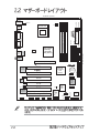
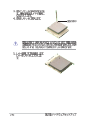
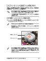
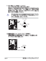
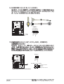
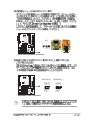
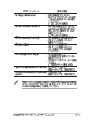
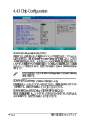
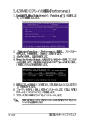
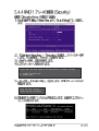
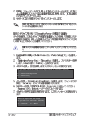
Motherboard
P4PE
Checklist
ii
iii
Features
Safeguards
iv
v
Federal Communications Commission Statement
This device complies with FCC Rules Part 15. Operation is subject to the
following two conditions:
• This device may not cause harmful interference, and
• This device must accept any interference received including interference
that may cause undesired operation.
This equipment has been tested and found to comply with the limits for a
Class B digital device, pursuant to Part 15 of the FCC Rules. These limits
are designed to provide reasonable protection against harmful interference
in a residential installation. This equipment generates, uses and can radiate
radio frequency energy and, if not installed and used in accordance with
manufacturer’s instructions, may cause harmful interference to radio
communications. However, there is no guarantee that interference will not
occur in a particular installation. If this equipment does cause harmful
interference to radio or television reception, which can be determined by
turning the equipment off and on, the user is encouraged to try to correct the
interference by one or more of the following measures:
• Reorient or relocate the receiving antenna.
• Increase the separation between the equipment and receiver.
• Connect the equipment to an outlet on a circuit different from that to
which the receiver is connected.
• Consult the dealer or an experienced radio/TV technician for help.
The use of shielded cables for connection of the monitor to the
graphics card is required to assure compliance with FCC regulations.
Changes or modifications to this unit not expressly approved by the
party responsible for compliance could void the user’s authority to
operate this equipment.
Canadian Department of Communications Statement
This digital apparatus does not exceed the Class B limits for radio noise
emissions from digital apparatus set out in the Radio Interference
Regulations of the Canadian Department of Communications.
This class B digital apparatus complies with Canadian ICES-003.
vi
vii
viii
ix
x
1
2
3
4
5
6
7
8
23
22
9
21
10
20
19
11
12
18
17
24
25
16 15 14 13
26
27
28
29
33
32
31
30
1
2
3
4
5
6
7
8
9
10
11
12
13
14
15
16
17
18
19
20
21
22
23
24
25
26
27
28
29
30
31
32
33
KBPWR1
CPU_FAN1
USB2.0 Top:
T:USB1 RJ-45
Intel 845PE
Memory
Controller
Hub (MCH)
ATX12V1
B:USB2
ATX Power Connector
FLOPPY1
4 5
PRI_IDE
2 3
EZ_PLUG1
0 1
SEC_IDE
DDR DIMM3 (64/72 bit, 184-pin module)
COM2
DDR DIMM2 (64/72 bit, 184-pin module)
PARALLEL PORT
COM1
DDR DIMM1 (64/72 bit, 184-pin module)
T: USB4
B: USB3
30.5cm (12.0in)
Socket 478
USB2.0
PWR_FAN1
PS/2KBMS
T: Mouse
B: Keyboard
CHA_FAN1
22.86cm (9.0in)
Top:Line In
Center:Line Out
Below:Mic In
Accelerated Graphics Port (AGP)
AGP_WARN1
®
Intel I/O
Controller
Hub
(ICH4)
P4PE
PCI2
CR2032 3V
Lithium Cell
CMOS Power
PRI_RAID1
PCI1
BroadCom
Gbit/Fast
BCM5702/4401
Ethernet
CLRTC1
SEC_SATA
PROMISE
SATA
Controller
PCI3
MODEM
Audio
Codec
PCI4
SPDIF1
ASUS
VIA
TRPWR1
PCI5
VT6307
Chipset
PCI6 / BlueMagic PCI Slot
Super
I/O
CD1
IEEE1394_1 IEEE1394_2
FP_AUDIO1
ASIC
with
Hardware
Monitor
SB_PWR1
CHASSIS1
SMB1
WPCI_USB
USB_56
PRI_SATA
IDE_LED1
AUX1
4Mbit
Firmware
Hub
IR1
GAME1
PANEL1
AGP_WARN1
ON
Incorrect
AGP Card
OFF
Correct
AGP Card
®
P4PE
P4PE Onboard LED
SB_PWR1
ON
Standby
Power
OFF
Powered
Off
90 - 100
80 Pins
®
P4PE
104 Pins
P4PE 184-Pin DDR DIMM Sockets
®
P4PE
P4PE Accelerated Graphics Port (AGP)
KBPWR1
1 2
®
P4PE
+5V
(Default)
2 3
+5VSB
P4PE Keyboard Power Setting
WPCI_USB
®
3 1
5 3
P4PE
4 2
Wireless
PCI_USB
P4PE WPCI_USB Setting
6 4
Original
PCI
reserved pin
(Default)
CLRTC1
®
P4PE
1 2
Disable
(Default)
P4PE Clear RTC RAM
2 3
Enable
®
TIP: If the case-mounted LED does not
light up, try reversing the 2-pin plug.
P4PE
IDE_LED1
P4PE HD Activity LED
FLOPPY1
NOTE: Orient the red markings on
the floppy ribbon cable to PIN 1.
®
P4PE
PIN 1
P4PE Floppy Disk Drive Connector
PRI_IDE
SEC_IDE
®
P4PE
NOTE: Orient the red markings
(usually zigzag) on the IDE
ribbon cable to PIN 1.
PIN 1 PIN 1
P4PE IDE Connectors
PRI_RAID1
NOTE: Orient the red markings
(usually zigzag) on the IDE
ribbon cable to PIN 1.
®
P4PE
P4PE RAID IDE Connectors
PIN 1
P4PE
P4PE SATA Connectors
GND
RSATA_TXP1
RSATA_TXN1
GND
RSATA_RXP1
RSATA_RXN1
GND
®
SEC_SATA1
PRI_SATA1
GND
RSATA_TXP2
RSATA_TXN2
GND
RSATA_RXP2
RSATA_RXN2
GND
Chassis Signal
GND
®
P4PE
+5VSB_MB
CHASSIS1
(Default)
P4PE Chassis Alarm Lead
SMB1
®
P4PE
Ground
SMBDATA
+3V
P4PE SMBus Connector
FLOATING
SMBCLK
1
ATXPWR1
EZ_PLUG1
Pin 1
®
P4PE
+12.0VDC
+5VSB
PWR_OK
GND
+5.0VDC
GND
+5.0VDC
GND
+3.3VDC
+3.3VDC
P4PE ATX & Auxiliary Power Connectors
+5.0VDC
+5.0VDC
-5.0VDC
GND
GND
GND
PS_ON#
GND
-12.0VDC
+3.3VDC
+12V
GND
GND
+5V
ATX12V1
+12V DC
GND
+12V DC
GND
GND
+12V
Rotation
CPU_FAN1
®
CHA_FAN1 PWR_FAN1
P4PE
Rotation
+12V
GND
GND
+12V
Rotation
P4PE 12-Volt Fan Connectors
®
P4PE
TRPWR1
Ground
TRPWR
P4PE Power Supply Thermal Connector
P4PE USB 2.0 Header
1
USB+5V
LP4LP4+
GND
USB+5V
LP5LP5+
GND
NC
P4PE
®
USB_56
+5V
J1B2
J1CY
GND
GND
J1CX
J1B1
+5V
GAME1
®
P4PE
P4PE Game Connector
MIDI_IN
J2B2
J2CY
MIDI_OUT
J2CX
J2B1
+5V
1
Modem-In
Ground
Ground
Modem-Out
MODEM1
®
P4PE
CD1(Black) AUX1 (White)
Left Audio Channel
Ground
Ground
Right Audio Channel
P4PE Internal Audio Connectors
IR1
Front View
Back View
1
®
IRRX
GND
IRTX
+5V
P4PE
+5V
IRTX
GND
(NC)
IRRX
P4PE Infrared Module Connector
IEEE1394_2
TPA1GND
TPB1+12V
GND
TPA0GND
TPB0+12V
GND
IEEE1394_1
®
P4PE IEEE-1394 Connectors
1
TPA1+
GND
TPB1+
+12V
1
TPA0+
GND
TPB0+
+12V
P4PE
®
SPDIFOUT
GND
+5V
SPDIF1
P4PE
®
BLINE_OUT_L
AGND
+5VA
BLINE_OUT_R
P4PE Digital Audio Connector
P4PE
MIC2
MICPWR
Line out_R
NC
Line out_L
FP_AUDIO1
P4PE Front Panel Audio Connector
®
P4PE
Reset
Ground
PLED
Keylock
Ground
ExtSMI#
Ground
PWRBIN
Ground
+5 V
Power LED
Speaker
Connector
+5V
Ground
Ground
Speaker
Keyboard Lock
Reset SW
SMI Lead
P4PE System Panel Connectors
ATX Power
Switch*
* Requires an ATX power supply.
ASUS EZ Flash V1.00
Copyright (C) 2002, ASUSTeK COMPUTER INC.
[Onboard BIOS Information]
BIOS Version
: ASUS P4PE ACPI BIOS Revision 1002
BIOS Model
: P4PE
BIOS Built Date : 04/16/02
Please Enter File Name for NEW BIOS: _
*Note: EZ Flash will copy file from A:\, Press [ESC] to reboot
[BIOS Information in File]
BIOS Version: P4PE Boot Block
WARNING! Continue to update the BIOS (Y/N)? _
Flash Memory:
SST 49LF004
Update Main BIOS area
(Y/N)? _
4.4.3.1 PCI IRQ Resource Exclusion
5.3.4 Winbond Voice Editor
MBFastTrak376 (tm) BIOS version 1.00
(c)2000-2005 Promise Technology, Inc. All Rights Reserved.
No Array defined...
Press <Ctrl-F> to enter FastBuild (tm) Utility
Or press <ESC> key to continue booting.
MBFastBuild (tm) Utility 1.21 (c) 1996-2001 Promise Technology, Inc.
[ Main Menu ]
Auto Setup . . . . . . . . . . [ 1 ]
View Drive Assignments . . . . [ 2 ]
View Array . . . . . . . . . . [ 3 ]
Delete Array . . . . . . . . . [ 4 ]
Rebuild Array. . . . . . . . . [ 5 ]
Controller Configuration . . . [ 6 ]
[ Keys Available ]
Press 1..6 to select Option
[ESC] Exit
Do you want the disk image to be duplicated to another? (Yes/No)
Y - Create and Duplicate
N - Create Only
Array has been created.
<Press any key to reboot>
Do you want the disk image to be duplicated to another? (Yes/No)
Y - Create and Duplicate
N - Create Only
Start to duplicate the image...
Do you want to continue? (Yes/No)
Y - Continue
N - Abort