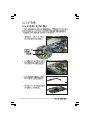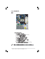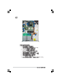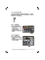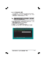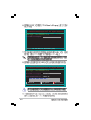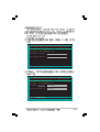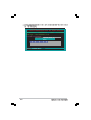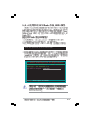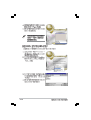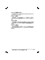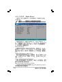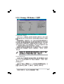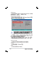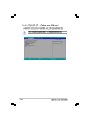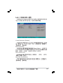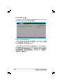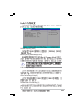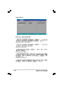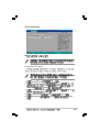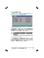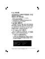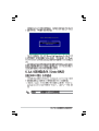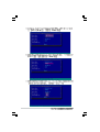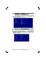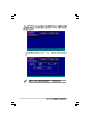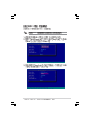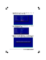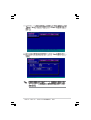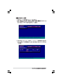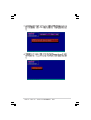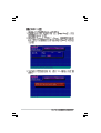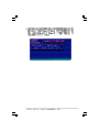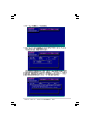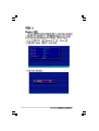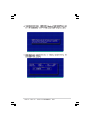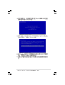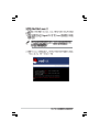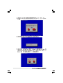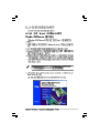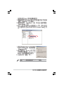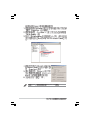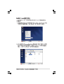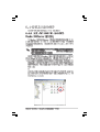
1
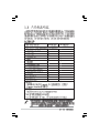
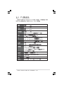
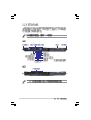
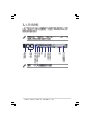
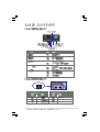
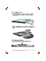
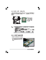
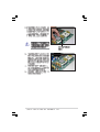
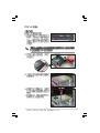
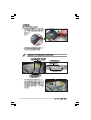
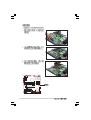
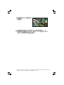
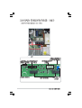
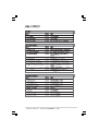
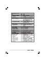
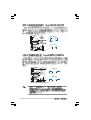
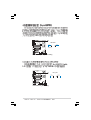
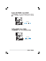
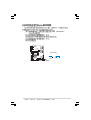
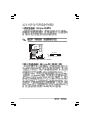
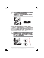
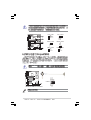
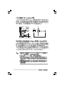
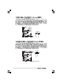
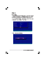
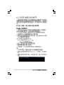
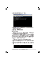
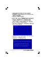
®
®
Intel Xeon Pentium
Windows MS-DOS
Intel
Microsoft
©2005
AP1600R-E2(AA2/AI2)
V1.0 C1837
2005
II
05
III
IV
V
VI
IC
VII
UPS
IC
VIII
IX
X
SATA RAID
1-2
USB
®
1U (AR14)
NCCH-DR
Intel® E7210 (MCH)
Intel® 6300ESB
Socket 604
Intel® Xeon 3.4GHz 800MHz FSB
Intel hyperThreading
4 184-pin
ECC non-ECC DDR
LAN
LAN1 Intel® PRO/1000 CT
LAN2 Intel® PRO/1000 MT
VGA
ATI RAGE-XL PCI-based VGA
1
64-bit/66MHz PCI-X 1.0
1
Mini-PCI
EM64T
PC3200/PC2700 unbuffer
4GB
(82547GI)
(82541GI)
8MB
Intel 6300ESB
-2
Ultra DMA 100/66/33
-2 SATA
Host Raid
RAID 0/1
SATA
Web
IDE
JBOD
Adaptec
ASWM
Automatic System
Restart, ASR
500W
600 mm
115V~230V 50Hz~60Hz
x 445 mm
x 43.6 mm
1-3
1.6.1
AA2
1-4
AI2
PS2
PS2
USB VGA
Gigabit
1.6.2
1-5
AA2
AI2
SATA
USB
1-6
LED
OFF
OFF
ASWM
Location
OFF
Location
LAN
OFF
/
RJ-45
ACT/LNK
SPEED
ACT/LINK LED
SPEED LED
OFF
OFF
10Mbps
100Mbps
1000Mbps
1-7
1-8
2-2
2-3
Intel Xeon
CPU2
Gold Arrow
Pin A1
CPU1
NCCH-DR
NCCH-DR CPU Socket 604
1.
CPU
CPU
2.
2-4
CPU
1
CPU
3.
CPU
4.
CPU Steppnig
CPU Socket 2 CPU2
Cache
CPUID
CPU
CPU 1
2-5
CPU
2-6
104 Pins
80 Pins
DIMM_A1
DIMM_A2
DIMM_B1
NCCH-DR
DIMM_B2
NCCH-DR 184-Pin DDR DIMM sockets
1.
CL CAS-Latency
2.
1GB
4GB
3.
4.
DDR
DIMM_A1
DIMM_A2
DIMM_B1
DIMM_B2
1
3
2
4
2-7
2-8
2-9
SATA
2-10
2-11
IDE Premary IDE
2-12
2-13
2-14
2-15
PCI
IRQ
2-16
IRQ
IRQ
11
3
2
1
4
5
6
7
1.
2.
3.
4.
5.
6.
7.
8.
9.
10.
11.
8
9
10
Rear FAN1
24-pin SSI
8-pin SSI
2 IDE
SATA
SATA
4-pin
SATA
(
(
)
)
(
(
SATA
SATA
)
SATA
)
Rear FAN2
2.8 (AA2)
2.9 (AI2)
2-17
10
1
3
2
4
5
6
7
1.
2.
3. 24-pin SSI
4. 8-pin SSI
5.
2 IDE
6.
7.
8.
9. 4-pin
10.
2-18
8
9
Rear FAN1
)
)
(
(
SATA
)
(
(
)
Rear FAN2
1.
2.
3.
4.
5.
2-19
24-pin SSI
8-pin
pin SSI
CD-ROM
SMBus
2-20
8-
2-21
2-22
2-23
NCCH-DR
2-24
2-25
2-26
2-27
2-28
75
3-2
100
19
3-3
3-4
26.8cm (10.5in)
ATX12V1
ATXPWR1
mPGA 604
PS/2KBMS
T: Mouse
KBPWR1
B: Keyboard
PSUSMB1
USB12
USBPW12
COM1
REAR_FAN2
LAN_EN1
Intel
CPU2
82547GI
Gigabit
Ethernet
Intel
mPGA 604
CPU_FAN2
FM_CPU2
DDR DIMM_A1 (64 bit,184-pin module)
LAN1
DDR DIMM_A2 (64 bit,184-pin module)
LAN2
DDR DIMM_B1 (64 bit,184-pin module)
CPU1
DDR DIMM_B2 (64 bit,184-pin module)
30.5cm (12in)
VGA
MCH
E7210
SB_PWR1
REAR_FAN1
FM_CPU1
CPU_FAN1
PCIX1 (64-bit, 66MHz 3V)
Intel
82541GI
Gigabit
Ethernet
PCIX2 (64-bit, 66MHz 3V)
FRNT_FAN2
LAN_EN2
FRNT_FAN1
PCI3 (32-bit, 33MHz 5V)
ATI
RAGE XL
VGA
Controller
PCI4 (32-bit, 33MHz 5V)
Intel
ICH
6300ESB
VGA_EN1
CLRTC1
8Mbit
Flash
BIOS
Super
I/O
PCI5 (32-bit, 33MHz 5V)
SATA1
USB34
USBPW34
CR2032 3V
Lithium Cell
CMOS Power
BMCSOCKET1
AUX_PANEL1
BMCCONN1
FLOPPY
BPSMB1
SEC_IDE
PRI_IDE
HDLED
RECOVERY
LPT1
COM2
NCCH-DR
PCIX1
4-2
SATA2
PANEL1
4-3
4-4
CLRTC1
2 1
NCCH-DR
NCCH-DR Clear RTC RAM
Normal
(Default)
3 2
Clear CMOS
4-5
FM_CPU2
2
1
DC mode
(Default)
3
2
PWM
FM_CPU1
2 3
1 2
DC mode
(Default)
NCCH-DR
PWM
NCCH-DR FM_CPU setting
USBPW12
2 3
1 2
+5V
(Default)
+5VSB
USBPW34
1 2
+5V
(Default)
NCCH-DR
NCCH-DR USB device wake-up
1.
USB
+5VSB
500mA/+5VSB
2.
+5VSB
4-6
2 3
+5VSB
KBPWR1
1 2
2 3
+5V
(Default)
+5VSB
NCCH-DR
NCCH-DR Keyboard power setting
LAN_EN1
1 2
Enable
(Default)
2 3
Disable
NCCH-DR
NCCH-DR LAN_EN1 setting
4-7
LAN_EN2
2 3
1 2
NCCH-DR
Enable
(Default)
Disable
NCCH-DR LAN_EN2 setting
VGA_EN1
1 2
NCCH-DR
NCCH-DR VGA setting
4-8
Enable
(Default)
2 3
Disable
RECOVERY
1 2
Normal
(Default)
2 3
BIOS Recovery
NCCH-DR
NCCH-DR BIOS recovery setting
4-9
5
FLOPPY
PIN 1
NOTE: Orient the red markings on
the floppy ribbon cable to PIN 1.
NCCH-DR
NCCH-DR Floppy disk drive connector
4-10
1.
IDE
2.
UltraDMA
UltraDMA/100/66 IDE
80
IDE
SEC_IDE
PIN 1
PRI_IDE
PIN 1
NOTE: Orient the red markings
(usually zigzag) on the IDE
ribbon cable to PIN 1.
NCCH-DR
NCCH-DR IDE connectors
Standard IDE
Serial ATA
/
Serial ATA RAID
[RAID]
5.4.5
BIOS
SATA mode
SATA2
GND
RSATA_TXP2
RSATA_TXN2
GND
RSATA_RXN2
RSATA_RXP2
GND
SATA1
NCCH-DR
GND
RSATA_TXP1
RSATA_TXN1
GND
RSATA_RXN1
RSATA_RXP1
GND
NCCH-DR SATA connectors
4-11
Serial ATA
Serial ATA
Serial ATA
Parallel ATA
RAID 0
RAID1
Serial ATA RAID
Serial ATA
2000 Service Pack 4
Windows XP Service Pack 1
SATA1
SATA2
Master
Slave
HDLED1
NCCH-DR
NC
ADD_IN_CARD_ACT#
ADD_IN_CARD_ACT#
NC
1
NCCH-DR
SCSI/SATA card activity LED connector
4-12
Windows
Rotation
+12V
GND
REAR_FAN1
FRNT_FAN1
NCCH-DR
GND
+12V
Rotation
NCCH-DR Fan connectors
REAR_FAN2
FRNT_FAN2
GND
+12V
Rotation
USB
USB+5V
USB_P4USB_P4+
GND
NC
IEEE 1394
CPU_FAN2
FANOUT6
Rotation
FANPWR3
GND
GND
FANPWR2
Rotation
FANOUT4
GND
+12V
Rotation
CPU_FAN1
NCCH-DR
NCCH-DR USB 2.0 connector
USB+5V
USB_P3USB_P3+
GND
USB34
4-13
COM2
PIN 1
NCCH-DR
NCCH-DR
Serial port2 (COM2) connector
2.0
SSI 24-pin ATX 12V
450W
8-pin +12V ATX
4-14
PSU
+5VSB
+5VSB
BMC_LANCLK#
BMC_SMBCLK#
PSON#
BMC_RSTBTN#
PWROK
PSONEN
AFD#
ERROR#
PINIT#
SLIN#
GND
GND
GND
GND
GND
GND
GND
GND
NCCH-DR Power connectors
NCCH-DR
NCCH-DR
NCCH-DR BMC connector
+5VSB
+5VSB
BMC_LANDATA#
BMC_SMBDATA#
BMC_PWRBTN#
PRESENCE#
SMIOUT#
GND
STB#
SPD0
SPD1
SPD2
SPD3
SPD4
SPD5
SPD6
SPD7
ACK#
BUSY
PE
SLCT
1
+12V CPU1
+12V CPU1
+12V CPU2
+12V CPU2
+3 Volts
-12 Volts
Ground
PSON#
Ground
Ground
Ground
-5 Volts
+5 Volts
+5 Volts
+5 Volts
Ground
GND
GND
GND
GND
+3 Volts
+3 Volts
Ground
+5 Volts
Ground
+5 Volts
Ground
Power OK
+5V Standby
+12 Volts
+12 Volts
+3 Volts
24-pin Power Connector
8-pin
For Power Supply
with 20-pin
Power Connector
LPT1
Pin 1
NCCH-DR Parallel port connector
NCCH-DR
BMCCONN1
1
2
4-15
BPSMB1
GND
I2C_6_DATA#
+5V
NCCH-DR
NCCH-DR SMBus connector
FAN_PWM
I2C_6_CLK#
1
+3.3V Remote Sense
GND
NC
PSU_I2CDATA
PSU_I2CCLK
PSUSMB1
NCCH-DR
NCCH-DR Power supply SMBus connector
4-16
NMIBTN#
GND
PWRBTN#
GND
NC
FP_RESET#
GND
HDLED+
GND
NCCH-DR
PLED+
NC
PLEDMLED+
MLEDNC
+5V
GND
GND
SPKROUT
+5VSB
1
INTTUDER
GND
LOCLED1+
LOCLED1LOCBTN#
GND
LOCLED2LOCLED2+
GND
I2CDATA
+5VSB
LANLINK1
LANACT1
LANACT2
LANLINK2
I2CDATA
AUX_PANEL1
NCCH-DR Auxiliary panel connector
NCCH-DR
PANEL1
NCCH-DR System panel connector
4-17
4-18
BIOS
BIOS
DOS
Windows XP
5-2
BIOS
AFUDOS
BIOS
AwardBIOS Flash Utility for ASUS V1.06
(C) Phoenix Technologies Ltd. All Rights Reserved
For Canterwood - NCCH-DRC-00
Flash Type - SST 49LF004A /3.3V
DATE:
07/14/2004
File Name to Program :
Message: Please input File Name!
5-3
AwardBIOS Flash Utility for ASUS V1.06
(C) Phoenix Technologies Ltd. All Rights Reserved
For Canterwood - NCCH-DRC-00
Flash Type - SST 49LF004A /3.3V
DATE:
07/14/2004
File Name to Program : 1001.bin
Message: Do You Want To Save BIOS (Y/N)
AwardBIOS Flash Utility for ASUS V1.06
(C) Phoenix Technologies Ltd. All Rights Reserved
For Canterwood - NCCH-DRC-00
Flash Type - SST 49LF004A /3.3V
DATE:
07/14/2004
File Name to Program : 1001.bin
Save 12345678901234567890123456789012
current BIOS as : 0FE00 OK
12345678901234567890123456789012
12345678901234567890123456789012
Write OK
12
12
12 No Update
123
123
123 Write Fail
Warning: Don’t Turn Off Power Or Reset System!
5-4
AwardBIOS Flash Utility for ASUS V1.06
(C) Phoenix Technologies Ltd. All Rights Reserved
For Canterwood - NCCH-DRC-00
Flash Type - SST 49LF004A /3.3V
DATE:
07/14/2004
File Name to Program : 1001.bin
Save current BIOS as :
Message:
AwardBIOS Flash Utility for ASUS V1.06
(C) Phoenix Technologies Ltd. All Rights Reserved
For Canterwood - NCCH-DRC-00
Flash Type - SST 49LF004A /3.3V
DATE:
07/14/2004
File Name to Program : 1001.bin
Checksum : 0E00
Save current BIOS as : old.bin
Message: Please Wait!
5-5
AwardBIOS Flash Utility for ASUS V1.06
(C) Phoenix Technologies Ltd. All Rights Reserved
For Canterwood - NCCH-DRC-00
Flash Type - SST 49LF004A /3.3V
DATE:
File Name to Program : 1001.bin
Now Backup System BIOS to
File!
12345678901234567890123456789012
12345678901234567890123456789012
12345678901234567890123456789012
12345678901234567890123456789012
Message: Please Wait!Reset
5-6
07/14/2004
BIOS
BIOS
Award BootBlock BIOS v.1.0
Copyright (C) 2000, Award Software, Inc.
BIOS ROM checksum error
Detecting IDE ATAPI device...
Found CD-ROM, try to Boot fromt it...Fail
Detecting floppy drive a media...
INSERT SYSTEM DISK AND PRESS ENTER_
AwardBIOS Flash Utility for ASUS V1.06
(C) Phoenix Technologies Ltd. All Rights Reserved
For Canterwood - NCCH-DRC-00
Flash Type - SST 49LF004A /3.3V
DATE:
07/14/2004
File Name to Program :
Message: Plase input File Name!
BIOS
5-7
Award BootBlock BIOS v.1.0
Copyright (C) 2000, Award Software, Inc.
BIOS ROM checksum error
Detecting IDE ATAPI device...
Found CD-ROM, try to Boot fromt it...Pass
1. FD 1.44MB System Type-(00)
Loading FreeDOS FAT KERNEL GO!
Press any key to boot from CDROM...
The BIOS was corrupted! Do you want to recover? (y/n)
Would you like to FLASH bios now? (y/n)
Yes or No _
AwardBIOS Flash Utility for ASUS V1.06
(C) Phoenix Technologies Ltd. All Rights Reserved
For Canterwood - NCCH-DRC-00
Flash Type - SST 49LF004A /3.3V
File Name to Program :
Message: Plase input File Name!
BIOS
5-8
DATE:
07/14/2004
Insert Disk press Enter or Esc to continue POST
AwardBIOS Flash Utility for ASUS V1.06
(C) Phoenix Technologies Ltd. All Rights Reserved
For Canterwood - NCCH-DRC-00
Flash Type - SST 49LF004A /3.3V
DATE:
07/14/2004
File Name to Program : 1001.bin
Message: Plase input File Name!
BIOS
BIOS
Source File Not Found!
5-9
ISP
BIOS
5-10
5-11
BIOS
5-12
1. BIOS
BIOS
BIOS
2.
3.
5.7
Load Setup Defaults
BIOS
http://www.asus.com.cn
BIOS
BIOS
5-13
Main
Advanced
Phoenix-Award BIOS CMOS Setup Utility
Power
Boot
Exit
System Time
System Date
11 : 10 : 30
Wed, Jui 21 2004
Legacy Diskette A:
Floppy 3 Mode Support
[1.44M, 3.5 in.]
[Disabled]
Primary IDE Master
Primary IDE Slave
Secondary IDE Master
Secondary IDE Slave
Third IDE Master
Fourth IDE Master
[None]
[None]
[None]
[None]
[None]
[None]
Base Mamory
Extended Memory
Total Memory
640K
260096K
261120K
Select Menu
Item Specific Help
Change the internal
clock.
↑↓ : Select Item
F1:Help
-/+: Change Value
→←
Defaults
ESC: Exit
→←: Select Menu
Select Sub-menu
F10: Save and Exit
5-14
F5: Setup
Enter:
/
5-15
5.2.1 BIOS
System Time
System Date
11 : 10 : 30
Wed, Jui 21 2004
Select Menu
Legacy Diskette A:
Floppy 3 Mode Support
[1.44M, 3.5 in.]
[Disabled]
Item Specific Help
Primary IDE Master
Primary IDE Slave
Secondary IDE Master
Secondary IDE Slave
Third IDE Master
Fourth IDE Master
[None]
[None]
[None]
[None]
[None]
[None]
Base Mamory
Extended Memory
Total Memory
640K
260096K
261120K
Time [hh:mm:ss]
Date [mm:dd:yy]
Legacy Diskette A [1.44M, 3.5 in.]
Floppy 3 Mode Support [Disabled]
Base/Extended/Total Memory [xxxK]
5-16
Change the internal
clock.
Primary Master
Primary IDE Master
Access Mode
Capacity
Cylinder
Head
Precomp
Landing Zone
Sector
PIO Mode
UDMA Mode
Transfer Mode
S.M.A.R.T Status
Select Menu
[Auto]
[Auto]
0 MB
0
0
0
0
0
[Auto]
[Auto]
None
None
Item Specific Help
Selects the type of
fixed disk connected
to the system.
[Manual] lets you
select the number of
cylinders, heads, etc.
Note: PRECOMP-65535
means NONE.
Primary IDE [Auto]
Access Mode [Auto]
PIO Mode
5-17
UDMA Mode
Manual detecting an IDE drive
Primary Master
Primary IDE Master
Access Mode
Capacity
Cylinder
Head
Precomp
Landing Zone
Sector
PIO Mode
UDMA Mode
Transfer Mode
S.M.A.R.T. Status
Capacity [xxxxx MB]
Cylinder
Head
5-18
Select Menu
[Manual]
[CHS]
0 MB
0
0
0
0
0
[Auto]
[Auto]
None
None
Item Specific Help
Selects the type of
fixed disk connected
to the system.
[Manual] lets you
select the number of
cylinders, heads, etc.
Note: PRECOMP=65535
means NONE.
Precomp
Landing Zone
Sector
Transfer Mode
S.M.A.R.T. Status
5-19
Advanced BIOS Features
CPU Configuration
Memory Configuration
Chipset
Onboard Device
PCIPnP
USB Configuration
5-20
Select Menu
Item Specific Help
Press Enter to set.
Advanced BIOS Features
Console Redirection
Baud Rate
Agent Address
Agent after boot
[Disabled]
19200
[Auto]
[Disabled]
Select Menu
Item Specific Help
Enabled - Attempt to
redirect console via
COM port.
Disabled - Attempt to
redirect console when
keyboard is absent.
Console Redirection [Disabled]
Baud Rate [19200]
Agent Address [Auto]
Agent after boot [Disabled]
5-21
CPU Configuration
CPU L1 & L2 Cache
Hyper-Threading Technology
[Enabled]
[Enabled]
CPU L1 & L2 Cache [Enabled]
Hyper-Threading Technology [Enabled]
5-22
Select Menu
Item Specific Help
Disable/Enable CPU L1/
L2 cache.
Memory Configuration
DRAM Frequency
Memory Timing Selectable
Cache Latency Time
Active to Precharge Delay
DRAM RAS# to CAS# Delay
DRAM RAS# Precharge
DRAM Data Integrity Mode
[Auto]
[By SPD]
2
6
3
3
[ECC]
Select Menu
Item Specific Help
Set DRAM Frequency.
DRAM Frequency [Auto]
Memory Timing Selectable [By SPD]
CAS Latency Time [2]
Active to Precharge Delay [6]
DRAM RAS# to CAS# Delay [3]
5-23
DRAM RAS# Precharge [3]
DRAM Data Integrity Mode [ECC]
Chipset
System BIOS Cacheable
Video BIOS Cacheable
Init Display First
Auto Detect PCI Clk
Select Menu
[Enabled]
[Disabled]
[PCI VGA Card]
[Enabled]
System BIOS Cacheable [Enabled]
Video BIOS Cacheable [Disabled]
Init Display First [PCI VGA Card]
Auto Detect PCI Clock [Enabled]
5-24
Item Specific Help
Press <Enter> to
enabled or disable
BIOS cacheable.
Onboard Device
H/W Jumper of CSA LAN
Onboard CSA LAN Boot ROM
H/W Jumper of ONB LAN
Onboard LAN Boot ROM
SuperIO Device
SATA Configuration
Enabled
[Disabled]
Enabled
[Disabled]
Select Menu
Item Specific Help
Enable/Disable Onboard
CSA LAN device boot
ROM support.
H/W Jumper of CSA LAN [Enabled]
Onboard CSA LAN Boot ROM [Disabled]
H/W Jumper of ONB LAN [Enabled]
Onboard LAN Boot ROM [Enabled]
5-25
SuperIO Device
SuperIO Device
Serial Port1 Address
Serial Port2 Address
Onboard Parallel Port
Parallel Port Mode
EPP Mode Select
ECP Mode Use DMA
[3F8/IRQ4]
[2F8/IRQ3]
[378/IRQ7]
[SPP]
EPP1.7
3
Serial Port 1 Address [3F8/IRQ4]
Serial Port 2 Address [2F8/IRQ3]
Onboard Parallel Port [378/IRQ7]
Parallel Port Mode [SPP]
EPP Mode Select [EPP1.7]
ECP Mode Use DMA [3]
5-26
Select Menu
Item Specific Help
Set Base I/O address
for serial port 1.
SATA Configuration
SATA Configuration
*** On-Chip Serial ATA Setting ***
On-Chip Serial ATA
[Auto]
SATA Mode
IDE
Serial ATA Port0 Mode
SATA0 master
Serial ATA Port1 Mode
SATA1 master
Select Menu
Item Specific Help
[Disabled]: Disable
SATA Controller.
[Auto]: Auto-arrange
the BIOS.
[Combined Mode]: PATA
and SATA are combined.
Max. of 2 IDE drives
on each channel.
[Enhanced Mode]:
Enable both SATA and
PATA. Max. of 6 IDE
drives are supported.
[SATA Only]: SATA is
opeating in legacy
mode.
On-chip Serial ATA [Auto]
a.
b.
[Auto] BIOS
ATA
[Combined Mode]
ATA
serial ATA
IDE
c.
[Enhanced Mode]
IDE
d.
[SATA Only]
IDE
e.
[Disabled]
ATA
ATA
IDE
ATA
ATA
ATA
ATA
RAID
5-27
SATA Mode [IDE]
Serial ATA Port0 Mode [SATA0 master]
Serial ATA Port1 Mode [SATA1 master]
5-28
PCIPnP
Resources Controlled By
IRQ Resources
PCI/VGA
INT Pin
INT Pin
INT Pin
INT Pin
INT Pin
INT Pin
INT Pin
INT Pin
Pallete Snoop
1 Assignment
2 Assignment
3 Assignment
4 Assignment
5 Assignment
6 Assignment
7 Assignment
8 Assignment
Select Menu
[Auto]
Item Specific Help
[Disabled]
[Auto]
[Auto]
[Auto]
[Auto]
[Auto]
[Auto]
[Auto]
[Auto]
Default is Disabled.
Select Enabled to
reset Extended System
Configuration Data
(ESCD) upon exiting
Setup, if you
installed a new add-on
card and the system
cannot boot due to a
serious conflict in
system configuration.
Resources Controlled By [Auto]
PCI/VGA Pallete Snoop [Disabled]
5-29
INT Pin 1~8 Assignment [Auto]
IRQ Resources
PCIPnP
Select Menu
Resources Controlled By
IRQ Resources
[Manual]
Item Specific Help
PCI/VGA
INT Pin
INT Pin
INT Pin
INT Pin
[Disabled]
[Auto]
[Auto]
[Auto]
[Auto]
When resources are
controlled manually,
assign each system
interrupt a type
depending on the type
of device using the
interrupt.
Pallete Snoop
1 Assignment
2 Assignment
3 Assignment
4 Assignment
Select Menu
IRQ Resources
IRQ-3
IRQ-4
IRQ-5
IRQ-7
IRQ-9
IRQ-10
IRQ-11
IRQ-12
IRQ-14
IRQ-15
assigned
assigned
assigned
assigned
assigned
assigned
assigned
assigned
assigned
assigned
to
to
to
to
to
to
to
to
to
to
[PCI
[PCI
[PCI
[PCI
[PCI
[PCI
[PCI
[PCI
[PCI
[PCI
Device]
Device]
Device]
Device]
Device]
Device]
Device]
Device]
Device]
Device]
IRQ-xx assigned to [PCI device]
5-30
Item Specific Help
Legacy ISA for devices
compliant with the
original PC AT bus
specification, PCI/ISA
PnP for devices
compliant with the
Plug and Play standard
whether designed for
PCI or ISa bus
architecture.
USB Configuration
USB Controller
USB 2.0 Support
USB Legacy Mode Support
[Enabled]
[Enabled]
[Enabled]
Select Menu
Item Specific Help
Configures the USB
controller.
USB Controller [Enabled]
USB 2.0 Support [Enabled]
USB Legacy Mode Support [Enabled]
5-31
ACPI APIC Support
APM Configuration
Hardware Configuration
[Enabled]
Select Menu
Item Specific Help
Enable/Disable ACPI
support for Operating
System.
ACPI APIC Support [Enabled]
5-32
APM Configuration
Power Management
HDD Power Down
Suspend Mode
Suspend Type
Restore on AC Power Loss
Video Off Method
Video Off In Suspend
MODEM Use IRQ
Soft-Off by PWR-BTN
Power On By PCI Devices
Power On By External Modem
POWER ON Function
KB Power On Password
Hot Key Power ON
Resume By Alarm
Date (of Month) Alarm
Time (hh:mm:ss) Alarm
[User Define]
[Disabled]
[Disabled]
[Stop Grant]
[Power Off]
[DPMS]
[Yes]
[3]
[Instant-Off]
[Enabled]
[Disabled]
[Button Only]
Enter
Ctrl-F1
[Disabled]
0
0 : 0 : 0
Select Menu
Item Specific Help
This field allows you
to set the automatic
power saving features.
Power Management [User Define]
HDD Power Down [Disabled]
Suspend Mode [Disabled]
Suspend Type [Stop Grant]
Restore on AC Power Loss [Power Off]
5-33
Video Off Method [DPMS]
Video Off In Suspend [Yes]
MODEM Use IRQ [3]
Soft-Off by PWR-BTTN [Instant-Off]
Power On by PCI Card [Enabled]
Power On by External Modem [Disabled]
Power On Function [BUTTON ONLY]
KB Power On Password [Enter]
5-34
Hot Key Power On Password [Ctrl-F1]
Resume by Alarm [Disabled]
Date (of Month) Alarm [0]
Time (hh:mm:ss) Alarm [0 : 0 : 0]
1.
2.
3.
4.
5.
6.
<tab>
<tab>
(
<Enter>
(
=0,
=23)
<Enter>
[minutes]
<Enter>
(
=0,
=59)
<Enter>
[seconds]
<Enter>
=0,
=59)
<Enter>
5-35
Hardware Monitor
Voltage Monitor
Smart Q-Fan Configuration
System Temperature1
CPU1 Temperature
CPU2 Temperature
N/B Front Temperature
N/B Rear Temperature
Front Fan1 Speed
CPU
Fan1 Speed
CPU
Fan2 Speed
Front Fan2 Speed
Rear Fan1 Speed
Rear Fan2 Speed
Select Menu
Item Specific Help
42oC/107oF
56oC/132oF
45oC/113oF
29oC/ 84oF
36oC/ 96oF
0 RPM
5152 RPM
5100 RPM
0 RPM
0 RPM
0 RPM
Press Enter to view.
Voltage Monitor
Voltage Monitor
CPU VCORE A (V)
+3.3V Voltage
+12V Voltage
+1.5V Voltage
+2.5V Voltage
+5VCC Voltage
+5VSB Voltage
VBAT Voltage
1.48V
3.26V
11.79V
1.49V
2.47V
4.99V
4.75V
3.10V
Select Menu
Item Specific Help
CPU VCORE Voltage, +3.3V Voltage, +12V Voltage, +1.5V Voltage,
+2.5V Voltage, +5VCC Voltage, +5VSB Voltage, VBAT Voltage,
5-36
Smart Q-Fan Configuration
Smart Q-Fan Configuration
Smart Fan Control
System Target Temperature
CPU1 Target Temperature
[Disabled]
50
55
Select Menu
Item Specific Help
Press Enter to enable
or disable the Smart
Fan.
Smart Fan Control [Disabled]
System Target Temperature [50]
CPU1 Target Temperature [55]
5-37
Select Menu
Boot Device Priority
Item Specific Help
Select Boot Device
Priority.
Hard Disk Boot Priority
Removable Device Priority
CD-ROM Boot Priority
Boot Settings Configuration
Security
5.6.1
Boot Device Priority
Boot Device Priority
1st Boot Device
2nd Boot Device
3rd Boot Device
[Removable]
[CDROM]
[Hard Disk]
1st Boot Device [Removable]
1nd Boot Device [CDROM]
3rd Boot Device [Hard Disk]
5-38
Select Menu
Item Specific Help
Select your Boot
Device Priority.
5.6.2 Hard Disk Boot Priority
Hard Disk Boot Priority
1. 1st Master: XXXXXXXX
2. Bootable Add-in Cards
Select Menu
Item Specific Help
Use <up> or <down>
arrow to select a
device, then press <+>
to move it up, or <->
to move it down the
list. Press <ESC> to
exit this menu.
5.6.3 Removable Device Priority
Removable Device Priority
1. Floppy Disks
Select Menu
Item Specific Help
Use <up> or <down>
arrow to select a
device, then press <+>
to move it up, or <->
to move it down the
list. Press <ESC> to
exit this menu.
5-39
5.6.4 CD-ROM Boot Priority
Removable Device Priority
1. 1st Slave: ASUS
CD-S520 /A
Select Menu
Item Specific Help
Use <up> or <down>
arrow to select a
device, then press <+>
to move it up, or <->
to move it down the
list. Press <ESC> to
exit this menu.
5.6.5
Boot Settings Configuration
Boot Settings Configuration
Boot Other Device
Quick Power On Self Test
Halt On
Case Open Warning
Boot Up Floppy Seek
Boot Up NumLock Status
Typematic Rate Setting
Typematic Rate (Chars/Sec)
Typematic Delay (Msec)
Full Screen Logo Show
[Enabled]
[Enabled]
[All Errors]
[Enabled]
[Enabled]
[On]
[Disabled]
6
250
[Enabled]
Boot Other Device [Enabled]
Quick Power On Self Test [Enabled]
5-40
Select Menu
Item Specific Help
Select your Boot
Device Priority.
Halt On [All Errors]
Case Open Warning [Enabled]
Boot Up Floppy Seek [Enabled]
Boot Up NumLock Status [On]
Typematic Rate Setting [Disabled]
Typematic Rate(Chars/Sec) [6]
Typematic Delay(Msec) [250]
Full Screen Logo Show [Enable]
5-41
5.6.6
Security
Security
Supervisor Password
User Password
Password Check
5-42
Select Menu
Clear
Clear
[Setup]
Item Specific Help
Supervisor password
control full access.
Password Check [Setup]
5-43
Exit & Save Changes
Exit & Discard Changes
Load Setup Defaults
Discard Changes
Select Menu
Item Specific Help
This option saves data
to CMOS before exiting
Setup.
Exit & Save Setup
Exit & Discard Changes
5-44
Discard Changes
5-45
5-46
6-2
6-3
RAID 0
6-4
6-5
6-6
Migrate
A
6-7
RAID 0
6-8
RAID 1
6-9
6-10
4
Build
Quick Init
Clear
B
C
6-11
6-12
6-13
6-14
6-15
RAID
RAID
6-16
RAID 1
SATA
6-17
6-18
6-19
6-20
6-21
6-22
6-23
6-24
6-25
6-26
6-27
6-28
6-29
*.zip
6-30
Windows
*.exe
6-31
6-32
BIN
ASSETUP.EXE
6-33
XXX
6-34
Intel(R)PRO/1000
BIN
ASSETUP.EXE
6-35
XXX
6-36
Intel(R)PRO/1000
6-37
6-38
Windows 2000
Windows 2003/XP
6-39
6-40