1
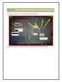
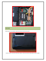
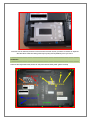
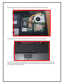
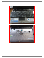
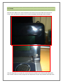
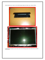
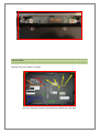
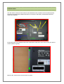
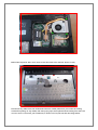
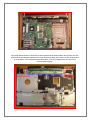
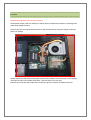
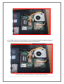
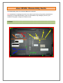
Asus M50Sv Disassembly Guide
This disassembly guide is for the Asus M50 series notebook.
NOTE: Remember to unplug your power cord, remove your battery and ground yourself before
attempting to disassemble anything. I am not responsible for any damages you do to your
notebook. This guide is simply for references only
=================================================================
OVERVIEW
=================================================================
=================================================================
MEMORY (RAM)
=================================================================
Unscrew the 5 screw (shown in yellow) and remove the back panel.
Spread the two clips on each side of the memory module until it pops out and remove.
=================================================================
HARD DRIVE
=================================================================
Unscrew the 2 screw (shown in blue) and remove the hard drive panel.
Unscrew 2 more screw near the bottom (shown in blue) and pull the black plastic strap to release.
Once the unit is removed, there are 4 more screws on each corner you have to remove to separate
the hard drive from the casing. This step is pretty self-explanatory once you see it.
=================================================================
KEYBOARD
=================================================================
Unscrew the keyboard screw (shown in red) and remove black panel (yellow screws)
Remove the one screw next to the electrical tape (the left most and shown in green)
Turn your notebook over and using a small screwdriver, push the 4 clips upwards
Be careful when removing the keyboard as it's still connected to the motherboard. To release the
cable from the motherboard, simply pull the white plastic locking arm outwards and pull the cable
to disconnect the cable connector
=================================================================
LCD SCREEN
=================================================================
Remove the 4 rubber screw-covers located on the corners of the screen bezel and remove the
screws. (You can leave the 2 rubber covers on the immediate left and right of the webcam)
Use your fingernails to pry open the screen bezel (You will have to be a little forceful during this
step. I found it easiest to start prying near the hinges and work your way upwards. The hinge cover
(shown below may or may not come off during this stage, but either way, it doesn't matter.
To remove the LCD panel, unscrew the 8 screw surrounding the panel and disconnect the inverter
shown below.
=================================================================
OPTICAL DRIVE
=================================================================
Remove the 2 screw (shown in orange)
Use your fingernails to pull the optical drive out the bay from the edge.
=================================================================
KEYBOARD BEZEL
=================================================================
You will need to remove all the screws on the underside of the notebook as well as the keyboard,
hard drive and optical drive (Note that there are 3 screws in the battery compartment that also
need to be removed.
On the left side of the notebook (where the optical drive was), there are 3 more screws you need to
remove (shown in green).
Near the fan, remove the 3 screws (shown in green)
Behind the keyboard, there are 2 more screws that need to be removes (shown in red)
Disconnect any cables from the motherboard that are visible (make sure you loosen the locking
arms before pulling on any cables) and start prying open the keyboard bezel starting from the front
corners. Once it's removed, your notebook (or what's left of it) will look like the image below.
The image below shows the underside of the keyboard bezel. Both speakers are screwed onto the
bezel and can be removed/replaced. The bezel itself has 4 cables that connect to the motherboard
(1 for speakers, 1 for the power button & hotkeys, 1 for the touchpad and 1 for the mouse
buttons/status lights).
=================================================================
CPU/GPU
=================================================================
NOTE: Removing these will void your warranty.
And because of that, I did not attempt to remove these 2 components. However, removing them
looks fairly straight forward.
Unscrew the CPU and chipset frame (shown in red) and disconnect the power supply to the fan
(shown in orange).
Gently remove the heat sink/cooling system (note: there usually is an extra screw or two holding
down the fan unit, but I couldn't find them... unscrew those if you see any).
Remove the screw near the purple frame of the CPU (shown in green) to unfasten the CPU.
For the GPU, remove the 2 screws (shown in red) to separate the heat sink. Remove another 2
screws (shown in blue) to unfasten the GPU from the motherboard.
You may have to lift and tilt the GPU at an angle before removing.
_____________________________________________________________________________________________________________