1
NOTEBOOK PC
USER’S MANUAL
Product Name:
Notebook PC
Manual Revision: 1.01 E356
Release Date:
September 1999
2
Notebook PC User’s Manual
FCC and DOC Safety Statements
Federal Communications Commission Statement
This device complies with FCC Rules Part 15. Operation is subject to the following two conditions:
•
•
This device may not cause harmful interference, and
This device must accept any interference received, including interference that may cause undesired operation.
This equipment has been tested and found to comply with the limits for a class B digital device, pursuant to Part 15 of the Federal
Communications Commission (FCC) rules. These limits are designed to provide reasonable protection against harmful interference in a residential installation. This equipment generates, uses, and can radiate radio frequency energy and, if not installed and
used in accordance with the instructions, may cause harmful interference to radio communications. However, there is no guarantee
that interference will not occur in a particular installation. If this equipment does cause harmful interference to radio or television
reception, which can be determined by turning the equipment off and on, the user is encouraged to try to correct the interference by
one or more of the following measures:
•
•
•
•
Reorient or relocate the receiving antenna.
Increase the separation between the equipment and receiver.
Connect the equipment into an outlet on a circuit different from that to which the receiver is connected.
Consult the dealer or an experienced radio/TV technician for help.
WARNING! The use of a shielded-type power cord is required in order to meet FCC emission limits and to prevent interference
to the nearby radio and television reception. It is essential that only the supplied power cord be used. Use only shielded cables
to connect I/O devices to this equipment. You are cautioned that changes or modifications not expressly approved by the party
responsible for compliance could void your authority to operate the equipment.
Canadian Department of Communications Statement
This digital apparatus does not exceed the Class B limits for radio noise emissions from digital apparatus set out in the Radio
Interference Regulations of the Canadian Department of Communications.
For use with AC Adaptor Model ADP-45GB (Pour Utiliser Avec Modele ADP-45GB)
Macrovision Corporation Product Notice
This product incorporates copyright protection technology that is protected by method claims of certain U.S. patents and other intellectual
property rights owned by Macrovision Corporation and other rights owners. Use of this copyright protection technology must be authorized
by Macrovision Corporation, and is intended for home and other limited viewing uses only unless otherwise authorized by Macrovision
Corporation. Reverse engineering or disassemby is prohibited.
Notebook PC User’s Manual
3
Notebook PC with Lithium-Ion Battery
Nordic Caution Statements
CAUTION! Danger of explosion if battery is incorrectly replaced. Replace only with the same or equivalent type
recommended by the manufacturer. Dispose of used batteries according to the manufacturer’s instructions. (English)
VORSICHT! Explosionsgetahr bei unsachgemäßen Austausch der Batterie. Ersatz nur durch denselben oder einem vom
Hersteller empfohlenem ähnlichen Typ. Entsorgung gebrauchter Batterien nach Angaben des Herstellers. (German)
ADVARSELI! Lithiumbatteri - Eksplosionsfare ved fejlagtig håndtering. Udskiftning må kun ske med batteri af samme
fabrikat og type. Levér det brugte batteri tilbage til leverandøren. (Danish)
VARNING! Explosionsfara vid felaktigt batteribyte. Använd samma batterityp eller en ekvivalent typ som rekommenderas
av apparattillverkaren. Kassera använt batteri enligt fabrikantens instruktion. (Swedish)
VAROITUS! Paristo voi räjähtää, jos se on virheellisesti asennettu. Vaihda paristo ainoastaan laitevalmistajan
sousittelemaan tyyppiin. Hävitä käytetty paristo valmistagan ohjeiden mukaisesti. (Finnish)
ATTENTION! Il y a danger d’explosion s’il y a remplacement incorrect de la batterie. Remplacer uniquement avec
une batterie du mêre type ou d’un type équivalent recommandé par le constructeur. Mettre au rebut les batteries usagées
conformément aux instructions du fabricant. (French)
ADVARSEL! Eksplosjonsfare ved feilaktig skifte av batteri. Benytt samme batteritype eller en tilsvarende type anbefalt
av apparatfabrikanten. Brukte batterier kasseres i henhold til fabrikantens instruksjoner. (Norwegian)
(Japanese)
4
Notebook PC User’s Manual
Contents
SECTION 1
INTRODUCTION
This Product ........................................................................................................................................ 9
This User’s Manual ............................................................................................................................. 9
Notes Used in This Manual ............................................................................................................ 9
Hardware Features ............................................................................................................................. 10
Caring Information ............................................................................................................................... 12
Transporting the Notebook PC ............................................................................................................ 13
Opening the Display Panel ............................................................................................................. 13
SECTION 2
COMPONENTS
Top Side .............................................................................................................................................. 14
Top Component Descriptions ......................................................................................................... 15
Front/Rear Illustrations ........................................................................................................................ 16
Front Side ....................................................................................................................................... 16
Rear Side ........................................................................................................................................ 16
Front/Rear Component Descriptions .............................................................................................. 17
Left/Right Illustrations .......................................................................................................................... 18
Left/Right Component Descriptions ................................................................................................ 19
Bottom Illustration ............................................................................................................................... 20
Bottom Component Descriptions .................................................................................................... 21
SECTION 3
GETTING STARTED
Power Connection ............................................................................................................................... 23
Powering On Your Notebook PC ......................................................................................................... 25
The Power-On Self Test (POST) .................................................................................................... 25
Save-to-Disk Partition ......................................................................................................................... 25
Notebook PC User’s Manual
5
Contents (Cont’)
Restarting or Rebooting ...................................................................................................................... 26
LED Indicators ..................................................................................................................................... 26
System Status Panel ........................................................................................................................... 27
System Status Panel Descriptions ................................................................................................. 27
Using the Keyboard ............................................................................................................................. 28
Specific Hot Keys ........................................................................................................................... 28
Keyboard as a Numeric Keypad ..................................................................................................... 29
Numeric Keypad as Cursors ........................................................................................................... 30
SECTION 4
BIOS SETUP
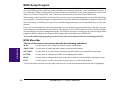
Introduction ......................................................................................................................................... 31
BIOS Setup Program .......................................................................................................................... 32
BIOS Menu Bar .............................................................................................................................. 32
BIOS Setup Program .......................................................................................................................... 32
BIOS Menu Bar .............................................................................................................................. 32
Legend Bar ..................................................................................................................................... 33
Sub-Menus ..................................................................................................................................... 33
General Help .................................................................................................................................. 34
Saving Changes and Exiting the Setup Program ........................................................................... 34
Main Menu .......................................................................................................................................... 34
IDE Primary Master ........................................................................................................................ 36
IDE Primary Slave .......................................................................................................................... 39
Advanced Menu .................................................................................................................................. 40
Security Menu ..................................................................................................................................... 44
The Power Menu ................................................................................................................................. 46
Boot Menu ........................................................................................................................................... 48
Exit Menu ............................................................................................................................................ 49
6
Notebook PC User’s Manual
Contents (Cont’)
SECTION 5
USING THE NOTEBOOK PC
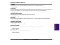
Introduction ......................................................................................................................................... 51
Storage Device Modules ..................................................................................................................... 51
Floppy Drive ........................................................................................................................................ 51
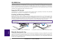
CD-ROM Drive .................................................................................................................................... 52
Supported CD Formats ................................................................................................................... 52
Inserting and Removing CD Discs .................................................................................................. 52
Manually Opening the Tray............................................................................................................. 52
DVD/MPEG2 Option ........................................................................................................................... 53
Hard Disk Drive ................................................................................................................................... 53
Important Handling Note ................................................................................................................. 53
Removing and Upgrading the HDD Module ................................................................................... 53
Pointing Device ................................................................................................................................... 54
Using the Touchpad ........................................................................................................................ 54
Caring for the Touchpad ................................................................................................................. 55
Display Panel ...................................................................................................................................... 56
Display Panel Care ......................................................................................................................... 56
External Display .............................................................................................................................. 56
PC Cards ............................................................................................................................................. 57
32-bit CardBus & Zoomed Video Port ............................................................................................ 57
Driver Support ................................................................................................................................ 57
Inserting and Removing a PC Card ................................................................................................ 58
Multimedia Sound System .................................................................................................................. 59
IR Wireless Communication ................................................................................................................ 60
Guidelines for using IR communication .......................................................................................... 60
Universal Serial Bus Port .................................................................................................................... 60
Driver Support ................................................................................................................................ 60
Notebook PC User’s Manual
7
Contents (Cont’)
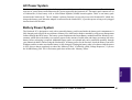
AC Power System ............................................................................................................................... 61
Battery Power System ......................................................................................................................... 61
Inserting the Battery Pack .............................................................................................................. 62
Removing the Battery Pack ............................................................................................................ 62
Warm-swapping the Battery Packs ................................................................................................ 63
Battery Pack Charging Function ..................................................................................................... 63
Using Battery Power ....................................................................................................................... 63
Power Management Modes ................................................................................................................ 64
Battery Gauge & Charging Status .................................................................................................. 64
Power Management Modes (Cont’) .................................................................................................... 65
Full Power Mode & Maximum Performance ................................................................................... 65
Standby Mode ................................................................................................................................ 65
Suspend to RAM / Suspend to Disk ............................................................................................... 65
System Memory Expansion ................................................................................................................ 66
APPENDIX ............................................................................................................................. 67
DVD Option ......................................................................................................................................... 67
8
Notebook PC User’s Manual
SECTION 1
I. Introduction
INTRODUCTION
This Product
The Notebook PC is the latest in PC technology with features that surpass most desktop PCs. Since the number of
features and components are so numerous, there may be different models for your market. Your dealer should provide
you with a standard component checklist and a list of optional components for the Notebook PC. Your dealer should also
provide you with warrranty and technical support.
This User’s Manual
You are reading the Notebook PC User’s Manual. This User’s Manual provides information on the various components
in this Notebook PC and how to use them. There are only a few sections in this reference guide as follows:
I.
II.
III.
IV.
V.
Introduction:
Components:
Getting Started:
BIOS:
Using:
This section introduces you to the Notebook PC.
This section gives you information on the Notebook PC’s components.
This section gives you information on getting started with the Notebook PC.
This section gives you information on configuring the BIOS software.
This section gives you information on using the Notebook PC’s components.
Notes Used in This Manual
A few notes are used throughout this guide that you should be aware of in order to complete certain tasks safely and
completely. These notes have different degrees of importance as described below:
NOTE!
IMPORTANT!
CAUTION!
WARNING!
Tips and information to aid in completing a task.
Information that must be followed in order to complete a task.
Information to prevent damage to the components when trying to complete a task.
Information to prevent injury to yourself when trying to complete a task.
Notebook PC User’s Manual
9
Hardware Features
I. Introduction
The Notebook PC features a wide range of standard features, upgrades, and options. The following gives you all your
current choices, many future options are being developed to keep up with the latest PC technologies.
10
•
Processor: 233MHz to 300MHz
A state-of-the-art Intel Pentium® II MMX Mobile Module supports future processor upgrades from the standard configuration of 233MHz. The Pentium® II has 32KB internal cache and 512KB Pipeline Burst Level-2.
•
Memory: 32MB to 288MB SDRAM
A 64-bit memory bus with 32MB of SDRAM is mounted onboard. A maximum of 288MB of memory can be
configured by using 16MB, 32MB, 64MB, or 128MB SO-DIMMs (144-pin). Two memory expansion slots are
available for SO-DIMMs for up to 288MB of memory.
•
Display: 14.1” TFT
Every model comes with an active matrix TFT that is capable of 1024 x 768 XGA resolution with 262,000
colors.
•
Graphics: 4MB AGP with DVD/MPEG2
The graphics and video subsystem includes a 4MB video memory and a high performance AGP graphics
controller with hardware 3D acceleration. An optional daughter card supports hardware DVD/MPEG2 video
playback. Simultaneous TV and LCD display is possible on every model using the built-in S-video composite
connector for video devices with SVHS input. Use the included S-video to RCA composite video cable for
video devices using an RCA input. The built-in VGA port provides a 15-pin D-Sub VGA connector for connecting a CRT monitor, an LCD monitor, or a desktop projector.
•
PC Cards: Two CardBus/Zoomed Video
PCMCIA 2.1 compliant sockets for two Type I, Type II, or one Type III PC cards are available on every model.
Both sockets support 32-bit CardBus and Zoomed Video is supported on the lower socket to accommodate any
Notebook PC expansion options, including memory cards, fax/modems, hard disks, SCSI adapters, high-speed
network adapters, and video capture/conference cards.
•
Hard Disk: 3.2GB - 8GB
A removable 2.5” UltraDMA/33 IDE hard disk drive is provided with 3.2GB capacity. Optional 4GB, 5GB,
6.4GB, and 8GB hard disk drives are available.
•
Floppy Disk: 1.44MB
Built-in standard 1.44MB floppy disk drive with Japanese 3-mode support.
•
Infrared: 4Mb/s
Front and back IrDA 1.1 compliant infrared ports are available on every model that can provide 115.2Kb/s SIR
(serial infrared) or 4Mb/s FIR (fast infrared) speeds for wireless file transfers or networking.
Notebook PC User’s Manual
•
Fax/Modem: 56K V.90
An optional built-in 56K modem with V.90 compression and 19.2K fax is available on each model. The fax/
modem supports video-conferencing I/F V.80 and host-based digital voice and data.
•
LCD Status Panel:
The LCD status panel displays AC-in, battery charging, battery gauge, hard disk/CD-ROM/floppy access, PC
card, suspend, caps lock, scroll lock, and number lock statuses.
•
Interface: Serial, Parallel, PS/2, Game/MIDI, USB
Each model provides one 9-pin D-Sub serial port that supports RS-232- and 16550-compatible serial devices,
one 25-pin D-sub ECP/EPP parallel port supports a standard parallel printer or third-party parallel port devices,
and one mini-DIN for PS/2 keyboard or PS/2 mouse (simultaneous use with included Y-cable). A 15-pin D-sub
connector supports a Joystick, Gamepad, or MIDI devices. The USB port supports USB devices.
Docking Connector - A 160-pin docking connector supports connection to the optional Port Replicator with an
additional PCMCIA socket.
•
•
Keyboard - 86 keys
Every model provides desktop-like 86 keys with 3mm travel and Microsoft Windows function keys. Tilt up feet
and palm rest provides comfortable typing.
•
Audio - 32-bit PCI Sound Blaster Pro compatible
Every model provides PCI AC97 stereo that is 32-bit PCI Sound Blaster Pro compatible with full duplex stereo
audio and 3D sound. Three audio jacks are used for stereo line-in/out, mono microphone-in and stereo headphone-out. Integrated microphone and stereo speakers provide quality audio with convenient access.
•
Power Management - APM 1.2 and ACPI 1.0
Every model features APM 1.2 power management built into the BIOS. These features are designed to conserve power to extend working time. Stand-by, suspend to disk, suspend to RAM, and ACPI 1.0 supported.
•
CD-ROM- 24X CD or 4X DVD (24X CD)
Every model includes a removable 24X CD-ROM drive. A DVD drive can be purchased instead of the CDROM drive to allow the use of both DVD (at 4X) and CD-ROM (at 24X) discs.
•
Battery - 9 cell Lithium-Ion
One battery pack will provide about 4.8A (52W). The system’s internal charger will automatically recharge the
battery pack when it is connected to the AC adapter. When battery power is low, there are warning beeps from
the speakers, a flashing battery gauge on the status panel, and warning through the Windows operating system.
•
AC Adapter - Output 19V DC, 2.4A, 45W
The AC adapter can accept several inputs from 100-240V AC 50/60Hz to accomodate any country.
•
Touchpad Pointing Device
The touchpad is a pointing device using a pressure-sensitive surface that allows cursor movement as well as
clicking through taping the tochpad or through pressing the two buttons below the touchpad.
Notebook PC User’s Manual
I. Introduction
Hardware Features (Cont’)
11
Caring Information
I. Introduction
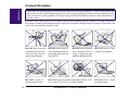
CAUTION! The following safety precautions will increase the life of the Notebook PC. Follow all precautions and
instructions. Except as described in this manual, refer all servicing to qualified personnel. Do not use damaged power
cords, accessories, or other peripherals. Do not use strong solvents such as thinners, benzene or other chemicals on or
near the surface.
Disconnect the AC power and remove the battery pack(s) before cleaning. Wipe the Notebook PC using a clean cellulose sponge or chamois cloth dampened with a solution of non-abrasive detergent and a few drops of warm water and
remove any extra moisture with a dry cloth.
12
DO NOT place on uneven
or unstable work surfaces.
Seek servicing if the casing has been damaged.
DO NOT place or drop objects on top and do not shove
any foreign objects into the
Notebook PC.
DO NOT expose to liquids,
rain, or moisture. Seek servicing if liquid has been
spilled into the Notebook PC.
DO NOT expose to
strong magnetic fields.
DO NOT expose to extreme temperatures (below 32˚F/
0˚C or above 122˚F/50˚C) or to direct sunlight.
Notebook PC User’s Manual
DO NOT expose to dirty
or dusty environments.
DO NOT press or touch
the display panel.
Transporting the Notebook PC
I. Introduction
To prepare the Notebook PC for transport, you should turn it off and disconnect all external peripherals to prevent
damage to the connectors. The hard disk drive’s head retracts when the power is turned off to prevent scratching of the
hard disk surface during transport. Therefore, you should not transport the Notebook PC while the power is still on.
Close the display panel and check that it is latched securely to the computer to protect the keyboard and display panel.
Floppy Disks
Make sure that the 1.44MB floppy disk drive does not contain a diskette when transporting the Notebook PC. When a
diskette is inserted into the floppy drive, the eject button protrudes out. If you attempt to transport the Notebook PC with
a diskette in the drive, you risk damaging the eject button and also risk scratching the surface of the diskette when the
floppy disk drive is jolted.
Protection
Use a carrying case such as the one supplied with your Notebook PC to protect it from dirt, water, shock, and scratches.
Battery
If you intend to use battery power, be sure to fully charge your battery pack and any optional battery packs before going
on long trips. Remember that the AC adapter charges the battery pack as long as it is plugged into the computer and an
AC power source. When the AC adapter is inserted, an orange LED will blink to show charging and will become solid
when the battery is fully charged. Be aware that it takes much longer to charge the battery pack when the Notebook PC
is in use.
Opening the Display Panel
Two spring-loaded latches on the display panel lock the display panel in the closed position when the Notebook PC is
not in use. To open the display panel, slide both of the display panel latches outward with your thumbs and then raise the
display panel with your thumbs and forefingers while holding the latches outward. You may then slowly adjust the
display panel to a comfortable viewing position.
CAUTION! Do not force the display panel down to the table or else the hinges will break!
Notebook PC User’s Manual
13
SECTION 2
COMPONENTS
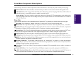
Top Side
II. Components
Display Panel Latches
Display Panel
Microphone
PC Card
(Optional)
Status Panel
CD-ROM Drive
TV
~
!
@
#
$
%
^
&
*
(
)
_
+
{
}
[
]
\
"
Keyboard
Battery Lock
Stereo Speakers
Battery Cloth Tab
Battery
Compartment Door
Battery Pack
Touchpad
Touchpad buttons
14
Notebook PC User’s Manual
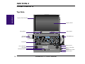
Top Component Descriptions
The following describes the top components of the Notebook PC as shown by the picture on the previous page.
Display Panel Latches: The display panel latches lock the display panel in the closed position.
Display Panel: The display panel uses active matrix TFT LCD technology and provides viewing like that of desktop
monitors.
II. Components
Microphone: The built-in microphone provides a source for inputting mono audio.
Status Panel: The display panel provides information on the Notebook PC’s AC-in, battery charging, battery gauge,
hard disk/CD-ROM/floppy access, PC card, suspend, caps lock, and scroll lock statuses.
PCMCIA Card: (see Left Side)
CD-ROM Drive: (see Right Side)
Keyboard: The keyboard provides 19mm full sized keys with 3mm travel and palm rest. Windows function keys also
help decrease navigation time.
Stereo Speakers: The two built-in speakers allow you to hear stereo audio without additional attachments.
Battery Lock: (see Right Side)
Touchpad: The touchpad pointing device with its two buttons allows the same functions as a desktop mouse.
Battery Pack: The battery pack is made of 9 Lithium-Ion cells. One battery pack will provide about 4.8A at 52W. The
system’s internal charger will automatically recharge the battery pack when it is connected to the AC adapter. By using
the power management features, battery power can last approximately 3.5 to 7 hours. The battery pack takes approximately 3 hours to fully recharge when turned off and 5 hours when in use. Battery drain and charging depends on
environment conditions and how the notebook is used. There is a low power warning from speakers and flashing battery
gauge on status indicator.
Battery Lock: (see Right Side)
Battery Cloth Tab: The battery cloth tab is used to pull out the battery pack.
Battery Compartment Door: The battery compartment door covers the battery compartment to protect against dirt.
Notebook PC User’s Manual
15
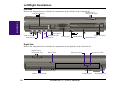
Front/Rear Illustrations
Front Side
Refer to the diagram below to identify the components on the front side of the Notebook PC.
II. Components
Infrared Port
Power Switch
(slides to the right)
LED Indicators
Rear Side
Refer to the diagram below to identify the components on the rear side of the Notebook PC.
Infrared Port
DC Input
USB Port
DC IN
PS/2 Keyboard/Mouse
Port
TV
Serial Port
16
Video Out
Parallel Port
Modem
Port
Docking Connector
Notebook PC User’s Manual
VGA Port
Game/MIDI Port
Front/Rear Component Descriptions
Front Side
The following describes the front components to the Notebook PC as shown by the picture on the previous page.
Infrared Port: The infrared (IrDA) communication port allows wireless data transfers through the front.
LED Indicators: The orange LED will blink when the battery pack is charging. The Green LED will be lit
when the power is on and blink when in standby (suspend) mode.
II. Components
Power Switch: The power switch is used to turn the power ON and OFF. The momentary switch slides to the
right and springs back to the left. Turning ON the power requires about one second and about two seconds to
turn OFF the power.
Rear Side
The following describes the rear components to the Notebook PC as shown by the picture on the previous page.
DC IN
TV
DC Input: The supplied AC adapter converts AC power to DC power for use with this jack.
Serial Port: The 9-pin D-Sub serial port supports serial devices such as a drawing tablet, mouse, or modem.
Video Out: The video out port supports video display devices such as a video recorder, television, or projector
through an S-Video (SVHS) connector (or RCA connector using the supplied adapter).
Parallel Port: The 25-pin D-Sub parallel/printer port supports parallel devices such as a printer or ZIP® drive.
this port also supports connection of the supplied floppy disk drive module using the supplied cable.
Infrared Port: The infrared (IrDA) communication port allows wireless data transfers through the rear.
Modem Port: Knockout panel for an optional built-in 56K V.90 modem using a standard RJ11 phone connector.
USB Port: The Universal Serial Bus (USB) port supports several USB compatible devices such as keyboards,
pointers, modems, and printers connected in series.
Docking Connector - The docking connector allows the Notebook PC to connect to a base unit through a
single 240-pin connector. The base unit can attach to desktop peripherals at all times such as keyboard, mouse,
monitor, network, modem, and other devices.
VGA Port - The 15-pin D-Sub VGA port supports a standard VGA-compatible device such as a monitor or
projector.
Game/MIDI Port - The 15-pin D-Sub Game/MIDI port supports a joystick, gamepad, or MIDI devices.
PS/2 Keyboard/Mouse Port - The PS/2 keyboard/mouse port is for connecting an external PS/2 mouse or
PS/2 keyboard to the Notebook PC if you do not want to use the built-in touchpad and keyboard.
Notebook PC User’s Manual
17
Left/Right Illustrations
Left Side
Refer to the diagram below to identify the components on the left side of the Notebook PC.
Display Latch
(slides to the right)
2 PCMCIA Sockets
II. Components
reset
Reset Button
Audio Line-Out
Audio Line-In
Headphone Jack
Microphone-In
Cooling Fan
Volume Knob
Floppy Disk Drive
Hard Disk Drive
Right Side
Refer to the diagram below to identify the components on the right side of the Notebook PC.
Display Latch
(slides to the left)
Battery Lock
CD Activity LED
Emergency Eject
K
CD-ROM Eject
Battery Compartment
18
Notebook PC User’s Manual
Kensington Lock
Left/Right Component Descriptions
Left Side
The following describes the left-side components to the Notebook PC as shown by the picture on the previous page.
reset
II. Components
PCMCIA: PCMCIA 2.1 compliant sockets for two Type I, Type II, or one Type III PC cards are available on
every model. Both sockets support 32-bit CardBus and Zoomed Video on the lower socket to accommodate
any Notebook PC expansion options, including memory cards, fax/modems, hard disks, SCSI adapters, and
high-speed network adapters.
Display Latch: The display latch is used to lock the display panel in the closed position. Slide both latches
forward to unlock the display panel.
Audio Line-Out: The stereo audio line-out is not amplified and is used to connect the Notebook PC’s audio
out to amplified speakers.
Audio Line-In: The stereo audio-in is used to connect external audio sources to the Notebook PC.
Headphone-Out: The stereo headphone jack is amplified and is used to connect a headphone.
Microphone-In: The mono microphone jack is used to connect an external microphone.
Cooling Fan: The cooling fan turns on when the temperature rises past a set threshold. The cooling fan is an
extra feature needed for upgrading to faster processors in the future.
Volume Knob: The volume knob allows adjustment of the built-in speakers’ audio volume level.
Hard Disk Drive: A removable 2.5” UltraDMA/33 IDE hard disk drive is provided with 3.2GB capacity.
Optional 4GB, 5GB, 6.4GB, and 8GB are available.
Floppy Disk Drive: Built-in standard 1.44MB floppy disk drive with Japanese 3-mode support.
Reset Button: Resets the system in case the Notebook PC hangs and CTRL-ALT-DEL & powering OFF does not work.
Right Side
The following describes the right-side components to the Notebook PC as shown by the picture on the previous page.
Display Latch: The display latch is used to lock the display panel in the closed position.
Battery Lock: The battery lock is used to secure the battery pack in place when the battery pack is inserted.
K
Emergency Eject: The CD-ROM emergency eject is used to eject a CD in case the electronic eject does not
work. Do not use this in place of the electronic eject. Electronic eject may be initialized by the CD-ROM eject
button or software.
CD Activity LED: The activity LED blinks proportionally to the CD-ROM drive activity.
Battery Compartment: The battery compartment has a door which houses the battery pack.
CD-ROM Eject: The CD-ROM eject is an electronic eject button for opening the CD-ROM tray.
Kensington® Lock: The Kensington® lock allows the Notebook PC to be secured using Kensington® Notebook PC security products.
Notebook PC User’s Manual
19
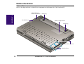
Bottom Illustration
Bottom Side
Refer to the diagram below to identify the components on the bottom side of the Notebook PC.
CD-ROM Latch
(slides toward back)
II. Components
CD-ROM Drive
Tilting Leg
Memory Compartment
Tilting Leg
Hard Disk Drive Screw
Hard Disk Drive
20
Notebook PC User’s Manual
Bottom Component Descriptions
Bottom Side
The following describes the bottom components to the Notebook PC as shown by the picture on the previous page.
CD-ROM Latch: The CD-ROM latch locks the CD-ROM in place when inserted. Slide the latch toward the back of
the Notebook PC to release the lock.
CD-ROM Drive: (see right side)
II. Components
Tilting Legs: The two legs on the bottom of the Notebook PC can be flipped out to provide a comfortable typing angle.
This reduces stress to the hands and wrists while typing.
Memory Compartment: The memory compartment holds the memory expansion sockets. The memory compartment
is to be opened by an authorized service agent only.
Hard Disk Drive Screw: The hard disk drive screw locks the hard disk drive in place when inserted.
Hard Disk Drive: (see left side)
CAUTION! Be sure that the hard disk drive screw is properly secured when transporting the Notebook PC. Without
the screw, the hard disk drive may fall out or have partial connection which could result in data loss.
Notebook PC User’s Manual
21
(This page was intentionally left blank.)
II. Components
22
Notebook PC User’s Manual
SECTION 3
GETTING STARTED
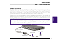
Power Connection
Your Notebook PC comes with a universal AC-DC converter. This means that you may connect the power cord to any
110V-120V outlet as well as 220V-240V outlets without setting switches or using power converters. Different countries
may require that an adapter be used to connect the provided US-standard AC power cord to a different standard. Most
hotels will provide universal outlets to support different power cords as well as voltages. It is always best to ask an
experienced traveler about AC outlet voltages when bringing foreign adapters to another country.
III. Starting
With the AC power cord connected to the AC-DC converter, connect the AC power cord to an AC outlet (preferably with
surge-protection) and then connect the DC plug to the Notebook PC. Connecting the AC-DC converter to the AC outlet
first will allow you to test the AC outlet’s power and the AC-DC converter itself for compatibility problems before
connecting the DC power to the Notebook PC.
CAUTION! Damage may occur if you use a different adapter to power the Notebook PC or use the Notebook PC’s
adapter to power other electrical devices. If there are smoke, burning scent, or extreme heat coming from the AC-DC
converter, seek servicing. Seek servicing if you suspected a faulty AC-DC converter. You may damage both your
battery pack(s) and the Notebook PC with a faulty AC-DC converter.
DC Power Cord
AC Power Outlet
AC Power Cord
AC-DC Converter
Notebook PC User’s Manual
23
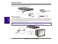
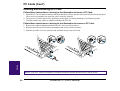
PS/2 Connection
A PS/2 mouse or PS/2 keyboard may be connected to the single PS/2 port. If you wish to connect two PS/2 devices, you
need to use the included PS/2 Y-adapter. The following shows both a PS/2 mouse and PS/2 keyboard connected to the
Notebook PC simultaneously using the PS/2 Y-adabpter.
PS/2 Keyboard
(not provided)
PS/2 Y-Adapter
PS/2 Mouse
TV Connection
(not provided)
III. Starting
The built-in S-Video (also knows as SVHS) connector can be used to connect an S-Video cable from the Notebook PC
to a video recording/displaying devices with an S-Video input connector. For connections to video recording/displaying
devices with an RCA input connector, use the provided S-Video to RCA adapter. The following example shows a
standard television connected to the Notebook PC.
NOTE! Only an SVideo-RCA adapter is provided. An RCA connection requires that you have your own male-male
RCA cable. An S-Video connection requires that you have your own male-male S-Video cable.
SVideo-RCA
Adapter
24
Male-Male RCA
Cable (not provided)
Notebook PC User’s Manual
Powering On Your Notebook PC
Slide the power switch forward momentarily and the Notebook PC’s power-on message will appear on the screen
followed by a short beep. If necessary, you may adjust the brightness by using the hot keys. If you need to run the BIOS
Setup to set or modify the system configuration, press [F2] upon bootup to enter the BIOS Setup. To turn off the
Notebook PC, slide and hold the power switch until the power turns off. To prevent accidental turning off the power, it
is designed to take longer to turn OFF the power then to turn ON the power.
IMPORTANT! Never turn off or reset your Notebook PC while the hard disk or floppy disk is in use and the activity
LED is lit; doing so can result in loss or destruction of your data. Always wait at least 5 seconds after turning off your
Notebook PC before turning it back on.
The Power-On Self Test (POST)
III. Starting
When you turn on the Notebook PC, it will first run through a series of software-controlled diagnostic tests called the
Power On Self Test (POST). The software that controls the POST is installed as a permanent part of the Notebook PC’s
architecture. The POST includes a record of the Notebook PC’s hardware configuration, which is used to make a
diagnostic check of the system. This record is created by using the BIOS Setup program. If the POST discovers a
difference between the record and the existing hardware, it will display a message on the screen prompting you to
correct the conflict by running the BIOS Setup. In most cases the record should be correct when you receive the
Notebook PC. When the test is finished, you may get a message reporting “No operating system found” if the hard disk
was not pre-loaded with an operating system. This indicates that the hard disk is correctly detected and ready for the
installation of a new operating system.
Save-to-Disk Partition
The Notebook PC supports Advanced Power Management to save battery power and extend its working time. One type
of power management is “Save-to-Disk.” Save-to-Disk is a suspend mode where your operating system and application
data is saved to a separate partition and retrieved when the Notebook PC comes out of suspend mode. A partition is a
space on the hard disk drive equivalent to having a second hard disk drive. If you would like the Notebook PC to support
the Save-to-Disk mode, the PHDISK.EXE utility is required to setup a Save-to-Disk partition on your hard disk.
IMPORTANT! All other partitions and their data will be cleared by using the PHDISK.EXE utility. This must be
done BEFORE you install an operating system onto your hard disk. The included hard disk drive comes with the
Save-to-Disk partition pre-configured from the factory.
Notebook PC User’s Manual
25
Restarting or Rebooting
After installing drivers, installing applications, or making configuration changes, you may be prompted to restart the
system to update the operating system and complete the installation process. To restart the system, use the “Restart the
computer?” command in Windows “Start | Shut Down.” If this does not restart the Notebook PC, you can reset the
Notebook PC by press the [Ctrl] + [Alt] + [Del] keys simultaneously. If none of these work, switch the Notebook PC’s
power OFF and then back ON. Wait 5 seconds before switching the Notebook PC back ON in order to allow the
electrical components to fully power down.
LED Indicators
The following table summarizes the functions of the Notebook PC’s front LED indicators. There are two LEDs, the left
one is amber in color and the right one is green in color.
III. Starting
Amber (Left)
Blinking
Solid
-------------------
26
Green (Right)
------------------Solid
Blinking
Meaning
The battery is charging.
The battery is fully charged.
The Notebook PC is powered on.
The Notebook PC is in Standby or Suspend Mode
Notebook PC User’s Manual
System Status Panel
Located under the display panel, the System Status Panel informs you of the Notebook PC’s current operating status at
a glance. Upon activating a certain function, a symbol or icon corresponding to that function appears in the window
indicating that the particular function is engaged. The icon will remain in the window until you deactivate that function.
The figure below shows the System Status Panel with all the displayable icons.
(1)
(2)
(3)
(4)
(5)
(6)
(7)
(8-10)
System Status Panel Descriptions
Indicates that the system is in the ON state.
(6) CD-ROM or DVD Activity
Indicates that the CD-ROM or DVD is being accessed.
III. Starting
(1) Power Management Status
Indicates that the system is in Standby or Suspend Mode (7) PC Cards Activity
Indicates that no PC cards are inserted.
as set by the power management system using the system
Indicates that a PC card is inserted in the lower slot.
BIOS setup.
Indicates that a PC card is inserted in the upper slot.
(2) AC Power-in
Indicates that PC cards are inserted in both slots.
Indicates that the system is operating on AC power.
(3) Battery Gauge & Charging Status
(8) Caps Lock
Indicates that [Caps Lock] is activated.
Indicates the amount of remaining battery power using a
(9) Number Lock
four bar gauge
Indicates that [Num Lock] is activated.
Indicates that the battery is charging when blinking.
(10) Embedded Numeric Keypad Lock
(4) Floppy Disk Activity
Indicates that the Embedded numeric keypad is enIndicates that the system is accessing the floppy disk gaged.
drive.
(11) Scroll Lock
(5) Hard Disk Activity
Indicates that [Scroll Lock] is activated.
Indicates that the hard disk is being accessed.
Notebook PC User’s Manual
27
Using the Keyboard
Specific Hot Keys
Some of the Notebook PC’s interface functions can be accessed through the keyboard by simultaneouly pressing the
bottom-left “Fn” key and one of the funtions colored in blue. The following table lists the hot key functions for the
Notebook PC.
Increases display brightness
Decreases display brightness
Suspend Mode
Toggles Embedded keypad lock off and on
Toggles display panel off and on
III. Starting
Toggles between LCD and external CRT/LCD monitors.
(Simultaneous display is supported)
TV
Switches to TV output devices
(NTSC or PAL video format selected by BIOS or VGA setup)
Toggles the numeric keypad off and on
Toggles the “ Scroll Lock “ off and on
Microsoft Windows 95™ Keys
There are two special Windows 95™ keys on the keyboard as described below.
The key with the Windows 95™ Logo activates the Start menu button at the bottom left of the screen.
The other key, which looks like a Windows menu with a small cursor, activates the properties menu and is
equivalent to pressing the right mouse button on a Windows object.
28
Notebook PC User’s Manual
Using the Keyboard (Cont’)
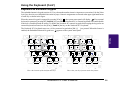
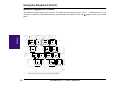
Keyboard as a Numeric Keypad
The embedded numeric keypad consists of 15 keys that make number intensive input more convenient. Like the [Num
Lock] key, these keys are labeled in blue on the keycaps. Numeric assignments are located at the upper right hand corner
of each key as shown in the figure.
. If an external
When the numeric keypad is engaged by pressing [ Fn ]+[ ], the system status panel will display
keyboard is connected, pressing the [ NumLk ] key on either the Notebook PC or external keyboard will enable/disable
NumLock of both keyboards in unison. To disable the Notebook PC numeric keypad while keeping the keypad on an
external keyboard activated, use the [ Fn ]+[ NumLk ] hot key on the Notebook PC’s keyboard.
The Notebook PC’s keyboard can act as a 10-key numeric keypad when [ Fn ]+[ ] are pressed. When this feature is
appears on the system status panel.
enabled, the Embedded Numeric Keypad icon
TV
&
*
(
)
_
_
^
{
{
[
[
"
This is the location of the dual function keys.
III. Starting
^
TV
"
This is how your keys function under this feature.
Notebook PC User’s Manual
29
Using the Keyboard (Cont’)
Numeric Keypad as Cursors
The numberic keypad can be used as cursors. To enable the cursor keypad, press [ Fn ]+[ ] and then press [ Fn ]+[
NumLk ] to enable the embedded numeric keypad and disable the NumLock. The icon appears on the system status
panel.
III. Starting
TV
_
{
[
"
This is how your keys function under this feature.
30
Notebook PC User’s Manual
SECTION 4
BIOS SETUP
Introduction
The BIOS (Basic Input and Output System) Setup is a menu driven software utility that enables you to make changes to
the system configuration and tailor your Notebook PC to reflect installed hardware, alter performance, and setup power
saving functions. It is a ROM-based program and also can be flashed with the latest version update through executing a
specific BIOS flashing utility program bundled in the Driver & Utility CD-ROM.
A battery backed-up CMOS RAM is used to record some basic system hardware information: clock, date, time, the error
handling, and etc., even when the power is off. When the Notebook PC is turned back on, the system is configured with
the values stored in the CMOS RAM.
With easy-to-use menus, you can configure these items through the BIOS Setup:
Date, time, and clock settings
Hard disk drives and peripherals
System-booting sequence
Password protection setting
Power management features
IV. BIOS Software
•
•
•
•
•
NOTE! Because the BIOS software is constantly being updated, the following BIOS screens and descriptions are for
reference purposes only and may not exactly reflect your BIOS screens.
The settings made in the BIOS Setup program intimately affect how the Notebook PC performs. It is important, therefore,
to first understand all the Setup options, and second, to make settings appropriate for the way you use the Notebook PC.
This Section will guide you through The Setup Program by providing clear explanations for all the options. A default
configuration has already been set. If you are either installing new devices or expanding main memory, you will need to
enter the BIOS Setup to reconfigure your Notebook PC.
The first part discusses how to move around in the BIOS Setup program, as well as how to specify and save your new
settings. Then, a brief discussion of the optional settings in the different sub-menus is given.
Notebook PC User’s Manual
31
BIOS Setup Program
The Setup program has been designed to make it as easy to use as possible. It is a menu driven program, which means
you can scroll through the various sub-menus and make your selections among the various predetermined choices. If
you accidentally change a setting and do not know which one to switch back to, the Setup program has a hot key that
allows you to return to the previous value. The hot keys are discussed in more detail later in this Section.
When turning on the Notebook PC for the first time, you may receive a message prompting you to run the BIOS Setup
by pressing [F2]. A warning message may appear on the screen if the hardware configuration is changed or if the POST
fails. This message will inform you of any errors or invalid settings and prompt you to run the BIOS Setup to correct the
problem.
Even if you are not prompted by a message instructing you to use the Setup program, at some time in the future you may
want to change the configuration of your computer. For example, you may want to enable the Security Password Feature
or make changes to the power management settings. It will then be necessary to reconfigure your system using the Setup
program so that the computer can recognize these changes and record them in the CMOS RAM.
To access the BIOS Setup program, press the [F2] key after the Notebook PC has booted through its POST.
BIOS Menu Bar
The top of the screen has a menu bar with the following selections:
IV. BIOS Software
MAIN
Use this menu to make changes to the basic system configuration.
ADVANCED
Use this menu to enable and make changes to the advanced features.
SECURITY
Use this menu to set a password to control bootup and control access to the BIOS setup menu.
POWER
Use this menu to configure and enable Power Management features.
BOOT
Use this menu to configure the default system device used to locate and load the Operating System.
EXIT
Use this menu to exit the current menu or specify how to exit the Setup program.
To access the menu bar items, press the right or left arrow key on the keyboard until the desired item is highlighted.
32
Notebook PC User’s Manual
BIOS Setup Program (Cont’)
Legend Bar
At the bottom of the Setup screen you will notice a legend bar. The keys in the legend bar allow you to navigate through
the various setup menus. The following table lists the keys found in the legend bar with their corresponding alternates
and functions.
F1
FUNCTION DESCRIPTION
Alt + H
Displays the General Help screen from anywhere in the BIOS Setup
Esc
Alt + X
Jumps to the Exit menu or returns to the main menu from a sub-menu
←
keypad arrow
Selects the menu item to the left
→
keypad arrow
Selects the menu item to the right
↑ or ↓
keypad arrows
Moves the cursor up and down between fields
Tab
Enter
Moves the cursor to the next position available in the field. If there is only
one field, the Tab key will move the highlight down to the next field
Shift + Tab
(none)
Moves the cursor to previous position available in the field. If there is only
one field, the Tab+Shift keys will move the highlight up to the previous field
- (minus key)
F5
Scrolls backward through the values for the highlighted field
+ (plus key)
F6, spacebar
Scrolls forward through the values for the highlighted field
Home
PgUp
Moves the cursor to the first field
End
PgDn
Moves the cursor to the last field
F9
(none)
Sets current menu items to default values
F10
(none)
Saves changes and exits Setup
IV. BIOS Software
LEGEND KEY ALTERNATE
Sub-Menus
Note that a right pointer symbol appears to the left of certain fields. This pointer indicates that a sub-menu can be
launched from this field. A sub-menu contains additional options for a field parameter. To call up a sub-menu, simply
move the cursor to highlight the field and press [Enter]. The sub-menu will then immediately appear. Use the legend
keys to enter values and move from field to field within a sub-menu just as you would within a menu. Use the [Esc] key
to return to the main menu.
Take some time to familiarize yourself with each of the legend keys and their corresponding functions. Practice navigating through the various menus and sub-menus. If you accidentally make unwanted changes to any of the fields, use the
set default hot key. While moving around through the Setup program, note that explanations appear in the Item Specific
Help window located to the right of each menu. This window displays the help text for the currently highlighted field.
Notebook PC User’s Manual
33
BIOS Setup Program (Cont’)
General Help
In addition to the Item Specific Help window, the BIOS setup program also provides a General Help screen. This screen
can be called up from any menu by simply pressing [F1] or the [Alt] + [H] combination. The General Help screen lists
the legend keys with their corresponding alternates and functions.
Saving Changes and Exiting the Setup Program
Refer to the Exit Menu Section of this Section for detailed information on saving changes and exiting the setup program.
When a scroll bar appears to the right of a help window, this indicates that there is more information to be displayed that
will not fit in the window. Use the [PgUp] and [PgDn] keys or the up and down arrow keys to scroll through the entire
help document. Press the Home key to display the first page, press End to go to the last page. To exit the help window,
press the [Enter] or the [Esc] key.
Main Menu
When the Setup program is accessed, the following screen appears:
Main
Advanced
PhoenixBIOS Setup Utility
Security
Power
Boot
Exit
IV. BIOS Software
Item Specific Help
System Time:
System Date:
[08:18:19]
[09/14/1998]
Diskette A:
1.44MB
IDE Primary Master
IDE Primary Slave
[3242MB]
[CD-ROM]
Video Display Device:
System Memory
Extended Memory
[LCD & CRT]
640 KB
31744 KB
F1 Help
Esc Exit
34
Select Item
Select Menu
Enter
Change Values
Select
Sub-Menu
<Tab>, <Shift-Tab>, or
<Enter> selects field .
F9 Setup Defaults
F10 Save and Exit
Notebook PC User’s Manual
Main Menu (Cont’)
System Time
Sets your system to the time that you specify (usually the current time). The format is hour, minute, second. Insert the
appropriate information. Use the [Tab] or [Shift] + [Tab] keys to move between the hour, minute, and second fields.
System Date
Sets your system to the date that you specify (usually the current date). The format is month, day, year. Type in the
appropriate information. Use the [Tab] or [Shift] + [Tab] keys to move between the month, day, and year fields.
Diskette A
This is a display-only field. The information is set for the type of floppy drive installed.
IDE Primary Master (see Main Sub-Menu)
IDE Primary Slave (see Main Sub-Menu)
Video Display Device (see Main Sub-Menu)
This field allows you to select the video display type, either autodetect LCD/CRT, or only use the Notebook PC’s LCD
panel, or only use an external CRT monitor.
[LCD & CRT] [LCD] [CRT]
System Memory
IV. BIOS Software
This field displays the amount of conventional memory detected by the system during bootup. You do not need to make
changes to this field. This is a display only field.
Extended Memory
This field displays the amount of extended memory detected by the system during bootup. You do not need to make
changes to this field. This is a display only field.
Notebook PC User’s Manual
35
Main Sub-Menu
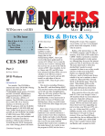
IDE Primary Master
This field is used to configure the IDE Hard Disk installed in the system. To configure a hard disk drive, move the cursor
to highlight the IDE Primary Master field and press the Enter key to enter the sub-menu.
Main
Advanced
PhoenixBIOS Setup Utility
Security
Power
Boot
IDE Primary Master
[3242MB]
Type:
Cylinders:
Heads
Sectors:
Maximum Capacity:
[Auto]
[ 6282]
[ 16]
[63]
3242MB
Multi-Sector Transfers:
LBA Mode Control:
32 Bit I/O:
Transfer Mode:
Ultra DMA Mode:
[16 Sectors]
[Enabled]
[Enabled]
[Fast PIO 4]
[Disabled]
IV. BIOS Software
F1 Help
Esc Exit
Select Item
Select Menu
Enter
Change Values
Select
Sub-Menu
Exit
Item Specific Help
Auto = autotypes
hard-disk drive
installed here.
None = force setting no
IDE device.
CD-ROM = a CD-ROM drive
is installed here.
User = you enter
parameters of hard-disk
drive installed at this
connection.
F9 Setup Defaults
F10 Save and Exit
NOTE! Before attempting to configure a hard disk drive, make sure you have the configuration information supplied
by the manufacturer of the drive. Incorrect settings may cause your system to not recognize the installed hard disk. To
allow the BIOS to detect the drive type automatically, select [AUTO].
36
Notebook PC User’s Manual
Main Sub-Menu (Cont’)
Type
Select Auto to automatically detect an IDE type drive. This option only works with standard built-in IDE drives. If
automatic detection is successful, the correct values will be filled in for the remaining fields on this sub-menu.
To configure a drive, select User. Manually enter the number of cylinders, heads and sectors per track for your drive.
Refer to your drive documentation or look on the drive for this information. If no drive is installed or if you are removing
a drive and not replacing it, select None. Set the type to CD-ROM to support an inserted CD-ROM or DVD drive
module and Removable ATAPI to support an inserted storage device module with an IDE interface as the primary
master.
Cylinders
This field configures the number of cylinders. Refer to your drive documentation to determine the correct value to enter
into this field. NOTE: To make changes to this field, the Type field must be set to User.
Heads
This field configures the number of read/write heads. Refer to your drive documentation to determine the correct value
to enter into this field. NOTE: To make changes to this field, the Type field must be set to User.
Sectors
This field configures the number of sectors per track. Refer to your drive documentation to determine the correct value
to enter into this field. NOTE: To make changes to this field, the Type field must be set to User.
IV. BIOS Software
Maximum Capacity
This field shows the drive’s maximum capacity calculated automatically by the BIOS from the drive information you
entered.
Multi-Sector Transfers
This option automatically sets the number of sectors per block to the highest number supported by the drive. This field can
also be configured manually. Note that when this field is automatically configured, the set value may not always be the
fastest value for the drive. Refer to the documentation that came with your hard drive to determine the optimal value and set
it manually. NOTE: To make changes to this field, the Type field must be set to User. The configuration options are:
[Disabled] [2 Sectors] [4 Sectors] [8 Sectors] [16 Sectors]
Notebook PC User’s Manual
37
Main Sub-Menu (Cont’)
LBA (Logical Block Addressing) Mode Control
When enabled, this option uses 28-bit addressing of the hard drive without regard for cylinders, heads, or sectors. Note
that Logical Block Access may decrease the access speed of the hard disk. However, LBA Mode is necessary for drives
with greater than 504MB in storage capacity. NOTE: To make changes to this field, the Type field must be set to User.
The configuration options are:
[Disabled] [Enabled]
32 Bit I/O
When enabled, this option speeds up communication between the CPU and the IDE controller. This option supports PCI
local bus only. ISA bus is not supported. The configuration options are:
[Disabled] [Enabled]
Transfer Mode
When enabled, this option speeds up communication between the system and the IDE controller by using enhanced I/O
transfer modes (PIO Modes). NOTE: To make changes to this field, the Type field must be set to User. The configuration options are:
[Standard] [Fast PIO 1] [Fast PIO 2] [Fast PIO 3] [Fast PIO 4] [FPIO 3 / DMA 1] [FPIO 4 /DMA 2]
Ultra DMA Mode
IV. BIOS Software
This field auto detects Ultra DMA capability (for improved transfer speeds and data integrity) for compatible IDE
devices. Set to Disable to suppress Ultra DMA capability. NOTE: To make changes to this field, the Type field must be
set to User. The configuration options are:
[Disabled] [Mode 0] [Mode 1] [Mode 2]
After using the legend keys to make your selections on this sub-menu, press the [Esc] key to exit back to the Main
menu. When the Main menu appears, you will notice that the drive size appear in the field for the hard disk drive
that you just configured.
38
Notebook PC User’s Manual
Main Sub-Menu (Cont’)
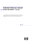
IDE Primary Slave
In this field, indicate the size of the disk drive or the device type, such as a CD-ROM drive. The arrow head icon
indicates that this field contains a sub-menu. The sub-menu is used to configure the IDE Hard Disk installed in the
system.
To configure a hard disk drive, move the cursor to highlight the IDE Primary Slave field, and press [Enter]. The submenu screen will appear. The fields and options on this sub-menu are the same as the Primary Master sub-menu described earlier. Set the type as CD-ROM in this field to support an inserted CD-ROM or DVD drive module and
Removable ATAPI to support an inserted storage device module with an IDE interface as the primary slave.
After using the legend keys to make your selections in this sub-menu, press the [Esc] key to return to the Main
menu.
Advanced
PhoenixBIOS Setup Utility
Security
Power
Boot
IDE Primary Slave
Type:
[Auto]
Multi-Sector Transfers:
LBA Mode Control:
32 Bit I/O:
Transfer Mode:
Ultra DMA Mode:
[Disabled]
[Disabled]
[Disabled]
[Standard]
[Disabled]
F1 Help
Esc Exit
Select Item
Select Menu
Enter
[CD-ROM]
Exit
Item Specific Help
This setting enables
or disables 32 bit IDE
data transfers.
IV. BIOS Software
Main
Change Values
Select
Sub-Menu
F9 Setup Defaults
F10 Save and Exit
Notebook PC User’s Manual
39
Advanced Menu
Selecting Advanced from the menu bar displays the Advanced menu. See the figure below.
Main
Advanced
PhoenixBIOS Setup Utility
Security
Power
Boot
Exit
Item Specific Help
Installed O/S:
[Win98]
I/O Device Configuration
Large Disk Access Mode:
TV mode:
IR position:
Internal Pointing Device:
Num Lock:
Local Bus IDE adapter:
Anti-Virus Feature:
QuickBoot Mode:
F1 Help
Esc Exit
Select Item
Select Menu
[Normal]
[NTSC]
[Back]
[Enabled]
[Auto]
[Primary]
[Enabled]
[Enabled]
Enter
Change Values
Select
Sub-Menu
Select the operating
system installed
on your system which
you will use most
commonly.
Note: An incorrect
setting can cause
some operating
systems to display
unexpected behavior.
F9 Setup Defaults
F10 Save and Exit
Installed O/S:
This field gives operating system information to the BIOS so that plug and play information can be set accordingly.
Select the appropriate operating system or select “Other” if your operating system is not listed.
[Other] [Win95] [Win98]
IV. BIOS Software
I/O Device Configuration
Pressing [Enter] when this field is highlighted calls up a sub-menu for configuring the Notebook PC’s serial and parallel
ports. See the Advanced sub-menu for descriptions of each sub-menu items.
Large Disk Access Mode
Specifies the type of operating system in use. The default, Normal, should be always used unless UNIX or Novell
Netware is being used. Available configurations are:
[Large] [Normal]
NOTE! The Large Disk Access mode controls how the disk controller accesses the disk volume. Setting the option
to Large may cause the hardware not to recognize DOS, Windows or other DOS based operating system disk
formats.
40
Notebook PC User’s Manual
Advanced Menu (Cont’)
TV Mode
Specifies the type of TV video output format for connecting to TV sets. Available formats are:
[NTSC] [PAL]
IR position
There is one infrared port in the back and one infrared port in the front of the Notebook PC. Only one port may be used
at one time. This field allow you to choose whether you want to use the front or the back infrared port.
[Front] [Back]
Internal Pointing Device
This field allows you to enable or disable the internal pointing device.
[Disabled] [Enabled]
Num Lock
Specifies the number lock function of the keypad when power is on. Auto keeps the last status during shutdown.
[Auto] [On] [Off]
Local Bus IDE adapter
Defines the search order of data.
IV. BIOS Software
[Disabled] [Primary] [Secondary] [Both]
Anti-Virus Feature
Protects the boot sector and partition table of your hard disk against accidental modifications.
[Disabled] [Enabled]
QuickBoot Mode
When Enabled, the system boots up faster then normal.
[Disabled] [Enabled]
Notebook PC User’s Manual
41
Advanced Sub-Menu
I/O Device Configuration
Main
Advanced
PhoenixBIOS Setup Utility
Security
Power
Boot
I/O Device Configuration
Seral port A:
Base I/O address:
IR Port
Base I/O address:
Mode:
DMA Channel
Parallel Port:
Mode:
Base I/O address:
F1 Help
Esc Exit
Item Specific Help
Configure serial port A
using options:
[User]
[3F8 IRQ4]
[User]
[2F8 IRQ3]
[FIR]
[DMA 3]
[User]
[Bi-directionl]
[378/IRQ7]
Select Item
Select Menu
Enter
Exit
Auto
[BIOS configuration]
User
[USER configuration]
Disabled
[NO configuration]
Change Values
Select
Sub-Menu
F9 Setup Defaults
F10 Save and Exit
IV. BIOS Software
NOTE! The presence of sub-items in this menu is dependent on certain relevant settings.
Serial Port A
This field allows you to configure the Notebook PC serial COM1 port. The following options are available:
[Disabled] [User] [Auto]
When User is selected, the Base I/O address menu item appears. The Base I/O address field becomes available
allowing you to set the serial port IRQ and I/O address. The following options are available:
[3F8, IRQ 4] [2F8, IRQ 3] [3E8, IRQ 4] [2E8, IRQ 3]
IR port
This field allows you to configure the Notebook PC’s serial IR port. The following options are available:
[Disabled] [User] [Auto]
42
Notebook PC User’s Manual
Advanced Sub-Menu (Cont’)
When User is selected, the Base I/O address menu item appears. This Mode field allows you to enable or disable the
Notebook PC’s Fast Infrared (FIR) communication module. The following configuration options are available:
[SIR] [FIR]
NOTE! The DMA channel menu item is available only when FIR is selected. The COM2 serial port is available for
system use only if the serial IR is Disabled. SIR enables standard IrDA IR support on COM2.
The Base I/O address field becomes available and you can set the serial port IRQ and I/O address. NOTE: This field
is only available when the IR port field is set to User. The following options are available:
[3F8, IRQ 4] [2F8, IRQ 3] [3E8, IRQ 4] [2E8, IRQ 3]
The DMA Channel field allows you to configure the DMA Channel used by the Fast Infrared port. NOTE: This field
is only available when the IR port Mode field is set to FIR. The following options are available:
[DMA 1] [DMA 3]
Parallel port
This field allows you to configure the Notebook PC parallel port. The following options are available:
[Disabled] [User] [Auto]
IV. BIOS Software
NOTE! Changing the default address and IRQ settings for COM1, COM2 and the LPT Port can cause conflicts with
other system devices or installed peripherals.
The Mode field allows you to configure the Notebook PC parallel port transmission mode. The following options are
available:
[Output only] [Bi-directional] [ECP] [EPP]
The Output only mode allows data output only. However, EPP and ECP are Bi-directional modes, allowing both data
input and output. The EPP and ECP modes are only supported with EPP and ECP aware peripherals.
EPP Mode: When the EPP mode is selected, the standard and bi-directional modes are also available. The EPP operates
on a two phase cycle. First, the host selects the register within a device for subsequent operations. Second, the host
performs a series of read and/or write byte operations to the selected register. There are four operations supported by
EPP: Address Write, Data Write, Address Read, and Data Read. All operations are performed asynchronously.
Notebook PC User’s Manual
43
Advanced Sub-Menu (Cont’)
ECP Mode: The port is both software and hardware compatible with existing parallel ports so that it may be used as a
standard printer mode if ECP is not required. ECP mode provides an automatic high burst-bandwidth channel that
supports DMA for ECP in both the forward (host to peripheral) and reverse (peripheral to host) direction.
Options in the field of Base I/O address are used to choose the I/O (port) address for the Parallel port. NOTE: This field
is only available when the Parallel port field is set to User. The available options are:
[378 / IRQ7] [378 / IRQ5] [278 / IRQ7] [278/ IRQ5]
The DMA Channel field allows you to configure the Parallel port DMA Channel for the selected ECP mode. NOTE:
This field is only available when the Parallel port field is set to User and the Mode field is set to ECP. The following
options are available:
[DMA 1] [DMA 3]
After using the legend keys to make your selections for the I/O Device Configuration sub-menu, press the [Esc]
key to exit back to the Advanced menu.
Security Menu
Main
Advanced
PhoenixBIOS Setup Utility
Security
Power
Boot
Exit
Item Specific Help
IV. BIOS Software
Set Password:
Password checking:
[Enter]
[Disabled]
Set password to enable
system security
F1 Help
Esc Exit
44
Select Item
Select Menu
Enter
Change Values
Select
Sub-Menu
F9 Setup Defaults
F10 Save and Exit
Notebook PC User’s Manual
Security Menu (Cont’)
The Notebook PC’s advanced system of security allows you to set a password to prevent unauthorized access to system
resources, data, and the BIOS Setup Program. This Section covers each parameter of the Security Setup. Selecting
Security from the menu bar displays the following menu:
A Note about Passwords
The BIOS Setup program allows you to specify passwords in the Security menu. The passwords control access to the
BIOS and certain Security menu options during system startup. The passwords are not case sensitive. In other words, it
makes no difference whether you enter a password using upper or lowercase letters.
The BIOS Setup program allows you to specify two separate passwords: a Supervisor password and a User password.
When disabled, anyone may access all BIOS Setup program functions. When enabled, the Supervisor password is
required for entering the BIOS Setup program and having full access to all Security menu options.
Set Password
This field allows you to set the User password. To set the User password, highlight this field and press [Enter].
Type the password and press [Enter]. You can type up to eight alphanumeric characters. Symbols and other keys are
ignored. To confirm the password, type the password again and press the [Enter]. The User password is now set. This
password allows full access to the BIOS Setup menus.
To clear the password, highlight this field and press [Enter]. The same dialog box as above will appear. Press [Enter]
twice. The password is now cleared.
IV. BIOS Software
Password checking
This option requires prior setting of the User password to function. When enabled, the system will then require the User
password before the system can bootup. When set to Always, the system will then require either the User password
before allowing access to the system when resuming from Save to Disk. Furthermore, booting from a diskette or CDROM will be disabled. The options for this field are:
[Disabled] [On Boot] [Always]
“On Boot” asks for a password when you enter BIOS setup and when booting from CD, floppy, or hard disk drive.
“Always” asks for a password during the “On Boot” items plus when resuming from Save-to-Memory and Save-toDisk.
Notebook PC User’s Manual
45
The Power Menu
The Power menu of the Setup program allows you to enable and adjust the advanced features of the Notebook PC, which
are designed to conserve power. Enabling these features will extend the life of the battery pack between charges. To make
changes to power management settings, select Power Savings from the menu bar. The following menu appears:
Main
Advanced
PhoenixBIOS Setup Utility
Security
Power
Boot
Exit
Item Specific Help
Power Savings:
Suspend Mode:
[Customized]
[Save To RAM]
Standby Timeout:
Auto Suspend Timeout:
[Off]
[Off]
Hard Disk Timeout:
Video Timeout:
[Disabled]
[Disabled]
Resume On Modem Ring:
Beep On Battery Low:
[On]
[Enabled]
F1 Help
Esc Exit
Select Item
Select Menu
Enter
Change Values
Select
Sub-Menu
Select Power Management
Mode. Choosing modes
changes system power
management settings .
Maximum Power Savings
conserves the greatest
amount of system power
while Maximum
Performance conserves
power but allows
greatest system
performance . To alter
these settings , choose
Customize . To turn off
power management ,
choose Disable.
F9 Setup Defaults
F10 Save and Exit
IV. BIOS Software
Power Savings
This option must be enabled to use any of the automatic power saving features. The options for this field are:
[Disabled] [Customized] [Maximum Power Savings] [Maximum Performance]
If this menu item is set to Disabled, power management features will not function regardless of other field settings on
this menu. The Customized option allows you to make your own selections in the Power menu. When set to Maximum
Power Savings, system power will be conserved to its greatest amount. The next four fields will then be set to predefined values that ensure maximum power savings. When this field is set to Maximum Performance, best system
performance is achieved with some power conservation. The next four fields will then be set to predefined values that
ensure maximum power savings.
Suspend Mode
This field determines the type of suspend mode when the Notebook PC enters power saving. The options for this field are:
[Save To RAM] [Save To Disk]
46
Notebook PC User’s Manual
Power Menu (Cont’)
Standby Timeout
This option is only enabled when Customized is selected in the Power Savings field. This field allows you to specify
the period of inactivity before the system automatically switches to Standby mode. In Standby mode, various devices
including the LCD backlight are powered off and the system enters a low power CPU state. Available options for this
field are:
[Off] [1 Minutes] [2 Minutes] [4 Minutes] [6 Minutes] [8 Minutes] [12 Minutes] [16 Minutes]
If Advanced Power Management (APM) is installed, this function will be controlled by APM and may function differently depending on the APM settings.
Auto Suspend Timeout
This field determines how much system idle time must pass before the system enters Suspend mode. When this field is
set to Off, the system cannot enter Suspend mode, which is the lowest power state for the Notebook PC. The possible
settings for this field are as follows:
[Off] [5 Minutes] [10 Minutes] [15 Minutes] [20 Minutes] [30 Minutes] [40 Minutes] [60 Minutes]
Hard Disk Timeout
This field allows you to specify the period of inactivity required before the hard disk spins down and enters power
saving mode. The possible options for this field are:
IV. BIOS Software
[Disabled] [1 Minute] [2 Minutes] [4 Minutes] [6 Minutes] [8 Minutes] [10 Minutes] [15 Minutes]
Video Timeout
This field allows you to specify the period of inactivity required before the display panel turns off. The possible options
for this field are:
[Disabled] [1 Minute] [2 Minutes] [4 Minutes] [6 Minutes] [8 Minutes] [10 Minutes] [15 Minutes]
Resume On Modem Ring
When this field is set to On, a modem ring will cause the system to resume from Suspend mode.
[Off] [On]
Beep On Battery Low
This option allows you to enable or disable the low battery warning beep.
[Disabled] [Enabled]
Notebook PC User’s Manual
47
Boot Menu
The Boot menu allows the user to specify the order in which the Notebook PC is to check for a device to boot the system.
To make changes, select Boot from the menu bar and the following screen appears:
Main
Advanced
PhoenixBIOS Setup Utility
Security
Power
Boot
Exit
Item Specific Help
1. [Removable Devices]
2. [Hard Drive]
3. [ATAPI CD-ROM Drive]
IV. BIOS Software
F1 Help
Esc Exit
Select Item
Select Menu
Enter
Use <↑> or <↓> to
select a device, then
press <+> to move it up
the list, or <-> to move
it down the list.
Press <Esc> to exit
this menu.
Change Values
Select
Sub-Menu
F9 Setup Defaults
F10 Save and Exit
Boot Sequence
The Boot menu allows you to select among the three possible boot devices listed using the up and down arrow keys . By
using the [+] or [Space] keys, you can promote devices and by using the [-] key, you can demote devices. Promotion or
demotion of devices alters the priority which the system uses to search for a boot device on system power up. The
default starts the search from removable devices, then the built-in hard disk drive, then the built-in CD-ROM drive.
48
Notebook PC User’s Manual
Exit Menu
Once you have made all of your selections from the various menus in the Setup program, you should save your changes
and exit Setup. Select Exit from the menu bar to display the following menu:
Main
Advanced
PhoenixBIOS Setup Utility
Security
Power
Boot
Exit
Item Specific Help
Exit Saving Changes
Exit Discarding Changes
Load Setup Defaults
Discard Changes
Save Changes
Select Item
Select Menu
Enter
Change Values
Select
Sub-Menu
F9 Setup Defaults
F10 Save and Exit
IV. BIOS Software
F1 Help
Esc Exit
Exit System Setup and
save your changes to
CMOS .
NOTE! Pressing the [Esc] key does not exit this menu. You must select one of the options from this menu or a menu
bar item to exit this menu.
Notebook PC User’s Manual
49
Exit Menu (Cont’)
Exit Saving Changes
Once you are finished making your selections, choose this option from the Exit menu to ensure the values you selected are
saved to the CMOS RAM. The CMOS RAM is sustained by an onboard backup battery and stays on even when the
Notebook PC is turned off. Once this option is selected, a confirmation is asked. Select Yes to save changes and exit.
Exit Discarding Changes
This option should only be used if you do not want to save the changes you have made to the Setup program. If you have
made changes to the fields other than system date, system time and password, the system will ask for confirmation
before exiting.
NOTE! If you attempt to exit the Setup program without saving your changes, the program will prompt you with a
message asking if you want to save your changes before exiting. Pressing the [Enter] key will still save changes while
exiting. You must select [No] and press [Enter] to leave without saving changes.
Load Setup Defaults
This option allows you to load the default values for each of the parameters on the Setup menus. When this option is
selected or if [F9] is pressed, a confirmation is requested. Select Yes to load default values. You can now select Exit
Saving Changes or make other changes before saving the values to the non-volatile RAM.
Discard Changes
IV. BIOS Software
This option allows you to discard the selections you made and restore the values you previously saved. After selecting
this option, all selections are updated and a confirmation is requested. Select Yes to discard any changes and load the
previously saved values.
Save Changes
This option saves your selections without exiting the Setup program. You can then return to other menus and make
changes. After selecting this option, all selections are saved and a confirmation is requested. Select Yes to save any
changes to the non-volatile RAM.
50
Notebook PC User’s Manual
SECTION 5
USING THE NOTEBOOK PC
Introduction
This Section describes the basic features and procedures for using your Notebook PC. Topics covered include the floppy
drive, CD-ROM drive, pointing device, and other input and output devices.
Storage Device Modules
Data storage and retrieval are two of the most fundamental tasks you will perform when working with your computer.
The Notebook PC is equipped with a 3.5” floppy drive, a hard disk drive, and a CD-ROM drive. An optional DVD may
be selected at the time of purchase. The following sections will cover instructions for operating each of these drives.
Floppy Drive
The Notebook PC features a 3.5 inch floppy disk drive that accepts standard 1.44MB (or 720KB) floppy diskettes. The
eject button is placed on the top edge of the floppy disk drive for easy access, unlike desktop PCs with the eject button
on the bottom of the floppy drive. There is no activity LED for the floppy drive, but instead a floppy diskette icon shows
on the status panel during reading or writing activity.
CAUTION! Because the eject button protrudes out when a floppy diskette is inserted, you must remove the floppy
diskette during transport to prevent breakage of the eject button.
V. Using
Eject Button
Notebook PC User’s Manual
51
CD-ROM Drive
The Notebook PC comes in two models, a CD-ROM model and a DVD model. The DVD model allows the use of both
CD-ROM and DVD discs. CD-ROM disks can store a large variety of information, including audio and video data, as
well as text files and programs with a maximum of 650MB. DVD discs have the same dimensions as CD-ROM discs
but have capacities of up to 8GB using both sides to store detailed audio and video surpassing the large Laser Discs
commonly used in high-fidelity home entertainment systems.
Supported CD Formats
The Notebook PC’s CD-ROM drive can support all the popular formats: Audio/Music CDs; Photo CDs; MS-DOS
MSCDEX Mode 1 and Mode 2; CD-ROM/XA; CD-I; and Video CDs.
Inserting and Removing CD Discs
Handle your CD discs with care, keeping in mind the important safety instructions from your CD disc suppliers. The
illustration below shows how to insert a CD disc into the CD-ROM drive. Do the reverse to remove the CD disc. Unlike
desktop PC CD-ROMs, the Notebook PC uses a hub to hold the CD disc in place at any angle. When inserting a CD disc,
it is important that the CD disc be pressed into the center hub or else the CD-ROM tray cannot be closed.
NOTE! The CD-ROM eject button is electronic and requires that the Notebook PC be powered ON in order to eject
the CD-ROM tray.
(1) Press the eject button (2) Slide CD-ROM tray out
(3) Snap disc onto hub (3) Press the CD-ROM tray back in
V. Using
Manually Opening the Tray
An Emergency Eject Button located inside a small hole besides the CD-ROM eject button (see Right Side in Section II)
allows you to open the tray manually when the power is off or if the CD-ROM tray cannot be ejected by pushing the CDROM eject button. To manually eject the CD-ROM tray, turn off the Notebook PC’s power and push the button inside
the hole with a straightened paper clip.
52
Notebook PC User’s Manual
DVD/MPEG2 Option
DVD, short for digital versatile disc or digital videodisc, is a new type of CD-ROM that holds a minimum of 4.7GB,
enough for a full-length movie or hours of music. The DVD specification supports discs with capacities from 4.7GB to
17GB and access rates up to 22.16MBps. With these capacities and access rates, DVD discs can provide you with a
dramatically-enhanced high-color, full-motion video, better graphics, sharper pictures, and Dolby® Digital Surround
for a theater-like experience.
MPEG, short for Moving Pictures Experts Group, is a standard for compressing video. MPEG2 is used in DVD movies
and is a broadcast-quality standard that provides better resolution than VHS tapes.
For DVD support on your Notebook PC you must select the DVD option at the time of purchase or return to your dealer
for an upgrade. The DVD option includes a DVD drive module, MPEG2 video decoder module, and drivers. In order to
view DVD titles, you must install the provided driver for the MPEG2 video decoder module and the DVD viewer
software (ALi MPEG DVD Player) included on the original Notebook PC support CD.
NOTE: The region setting may be changed up to five times using the viewer software. The Notebook PC’s DVD drive
is only single-sided, double-sided DVD (8.5GB and higher) requires reversing the disc in order to access the reverse
side. For more specifications, please see the Appendix at the end of this User’s Manual.
Hard Disk Drive
Hard disk drives have higher capacities and operate at much faster speeds than floppy disk drive or CD-ROM drives. Your
Notebook PC comes equipped with a miniature 2.5inch enhanced IDE hard disk drive designed specially for Notebook
PCs. Enhanced IDE drives provide a reliable, fast, and cost-effective mass storage solution in the PC storage industry. The
high speed transfer modes supported are Ultra DMA/33 up to 33MB/sec and PIO mode 4 up to 16.6MB/sec.
Important Handling Note
Improper handling during transit may damage the hard disk drive. Handle the Notebook PC carefully and keep it away
from static electricity and strong vibrations or impact. The hard disk drive is the most sensitive component of the
Notebook PC and will likely be the first or only component that is damaged if the Notebook PC is dropped.
V. Using
Removing and Upgrading the HDD Module
The Notebook PC is shipped with a single hard disk drive. You may upgrade to a higher capacity hard disk drive (currently
up to 8GB) or have multiple hard disk drives (to be used one at a time) for multiple operating systems or multiple uses.
When removing or inserting the hard disk drive, the Notebook PC’s power must be turned OFF. The large black screw (see
Bottom Side in Section II) securing the hard disk drive tray can be unscrewed using a coin. The hard disk can be easily
removed or inserted within its tray. Additional trays should be purchased for additional hard disk drives.
Notebook PC User’s Manual
53
Pointing Device
The Notebook PC’s integrated Touchpad pointing device is fully compatible with the two-button PS/2 mouse. The
Touchpad is pressure sensitive and contains no moving parts; therefore, mechanical failures are unlikely. A device driver
is still required for working with some application software. See the Driver & Utility Guide for information on drivers
and utilities for the Touchpad.
Touchpad
Left
Right
Using the Touchpad
Light pressure with the tip of your finger is all that is required to operate the Touchpad. Do not use pens or any other
items with sharp tips because they may scratch the pad and damage it permanently. The Touchpad’s primary function is
to move the cursor around on the screen with the use of your fingertip. The illustrations shown below describe how to
use the Touchpad under Windows.
Moving the cursor - Place your finger in the center of the Touchpad and do the following to more the cursor:
Up - Slide your finger forward
Down - Slide your finger backward
Left - Slide you finger to the left
Right - Slide your finger to the right
Clicking/Tapping - With the cursor over an item, press the left button or use the fingertip to touch the Touchpad lightly
and leaving the finger on the touchpad until the item is selected. The selected item will change color.
V. Using
Clicking
54
Tapping
Notebook PC User’s Manual
Pointing Device (Cont’)
Double-clicking/Double-tapping - This is a common skill for launching a program directly from the corresponding
icon you select. Move the cursor over the icon you wish to execute, press the left button or tap the pad twice in rapid
succession, and the system launches the corresponding program. If the interval between the clicks or taps is too long, the
operation will not be executed. You can set the double-click speed using the Windows Control Panel “Mouse.”
Double-Clicking
Double-Tapping
Dragging - Dragging means to pick up an item and place it anywhere on the screen you wish. You can move the cursor
over the item you select, and while keeping the left button depressed, moving the cursor to the desired location, then
release the button. Or, you can simply double-tap on the item and hold while dragging the item with your fingertip.
Dragging-Clicking
Dragging-Tapping
Caring for the Touchpad
The Touchpad is a pressure sensitive device. If not properly cared for, it can be easily damaged. Take note of the
following precautions.
V. Using
• Make sure the Touchpad does not come into contact with dirt, liquids or grease.
• Do not touch the Touchpad if your fingers are dirty or wet.
• Do not rest heavy objects on the Touchpad or the Touchpad buttons.
NOTE! The Touchpad responds to movement not force. Do not tap the surface too hard. Tapping too hard does not
increase the responsiveness of the Touchpad. The Touchpad responds best to light pressure.
Notebook PC User’s Manual
55
Display Panel
The Notebook PC comes with a 14.1” color Thin-Film-Transistor (TFT) Active Matrix display panel that outputs XGA
1024 x 768 resolution with 262,000 colors (32-bit true color). You can also hook up an external CRT or LCD monitor
through the VGA connector or just connect a video device such as a TV set through the Video out connector.
Display Panel Care
The LCD screen is very delicate and requires careful handling. Pay attention to the following precautions:
•
•
•
•
When not in use, keep the display panel closed to prevent dust accumulation.
Do not use chemical cleaners on the screen. Wipe only with a dry cloth or tissue.
Do not put your fingers or any objects directly on the screen.
Do not press or lay any objects on the machine when it is closed.
External Display
With a monitor or TV set is connected, you can use the toggle hot keys to switch between the display outputs. Two
modes are available: (1) Simultaneous display of both LCD display panel and external monitor (2) TV video output to
TV set or VCR (in NTSC or PAL/SECAM).
V. Using
56
Notebook PC User’s Manual
PC Cards
The Notebook PC has two PC Card sockets designed to interface with two Type I or Type II cards, or stacked to
accommodate one Type III card. It allows you to expand and customize your computer to meet a wide range of application needs. The PC Card standard accommodates a number of function, communication or data storage expansion
options, such as Memory/Flash Cards, FAX/Modems, Hard Disks, and Networking Adapters. The Notebook PC fully
supports PCMCIA 2.1, 32-bit CardBus, and Zoomed Video Port. The lower socket is #1 and the upper socket is #2.
Socket 2
Socket 2 eject button
Socket 1
Socket 1 eject button
32-bit CardBus & Zoomed Video Port
The CardBus allows PC Cards and their hosts to use 32-bit bus mastering and operate at speeds of up to 33MHz, transferring
data in burst modes comparable with PCI’s 132MB per second. By comparison, the standard 16-bit PC Card bus can handle
only 20MB per second. Since the Notebook PC is equipped with CardBus’ broader, faster data pathway, it can handle
bandwidth-hungry operations, such as 100Mbps Fast Ethernet, Fast SCSI peripherals, and ISDN-based video conferencing
that are cutting-edge even for desktop systems. The CardBus peripherals support plug and play.
The CardBus socket is backward-compatible with 16-bit PC Cards serving at 5 volts operation while CardBus operates
at 3.3 volts to reduce power consumption.
As part of the Notebook PC’s advanced architecture, the Zoomed Video specification provides for full frame-rate video
display channel for applications like MPEG decoders for movies and games, TV tuners, live video input, video capturing, and video conferencing. The ZV Port allows video data on a PC Card to be transferred directly into the VGA frame
buffer, bypassing the CPU and PCI system bus. It can promise a high quality real-time full-motion video playback
without holding back the CPU and system bus performance.
Driver Support
Notebook PC User’s Manual
V. Using
The supplied Windows 98 operating system comes already equipped with the drivers that allow your PC to recognize
PC cards and provide PC Card service. However, new PC cards may need software driver upgrades. Please read the
individual PC card documentation for information on driver support of specific operating systems.
57
PC Cards (Cont’)
Inserting and Removing a PC Card
Follow these instructions, referring to the illustration to insert a PC Card:
1. Insert the PC Card, with the connector side first and label side up, into the socket until it locks firmly into place.
The eject lever protrudes out when the card is correctly inserted.
2. The eject lever can be tucked in by pushing it to the right, preventing breakage or accidental ejection.
3. Carefully connect any cables or adapters needed by the PC card.
Follow these instructions, referring to the illustration to remove a PC Card:
1. Remove any cables or adapters attached to the PC card you wish to remove.
2. Raise the tip of the eject lever that corresponds to the card you want to remove.
3. Press the tip of the lever in to eject the card, and then slowly remove the card.
V. Using
NOTE! Type lll PC cards are designed to fit with the connector inserted into the lower PCMCIA socket.
58
Notebook PC User’s Manual
Multimedia Sound System
The Notebook PC’s built-in audio capabilities allow you to take advantage of a wide range of education and entertainment multimedia software available on today’s growing market. The multimedia sound system features an integrated
digital audio controller that produces rich, vibrant sound in high quality 16-bit stereo. With a pair of integrated stereo
speakers, a built-in microphone, and both input and output audio jacks for external audio devices, the Notebook PC
fulfills most multimedia computing needs. All audio features are software controlled.
The Notebook PC’s multimedia sound system includes the following features:
Built-in OPL3 FM-synthesizer
Sound Blaster Pro compatibility
Windows Sound System compatibility
Full Duplex operation
Built-in MPU401 Compatible MIDI/Game port
3D sound effect support
16-bit digitized audio playback
A built-in microphone for convenient recording
Two integrated stereo speakers
Digitized audio recording through the Notebook PC’s built-in microphone or external source
V. Using
•
•
•
•
•
•
•
•
•
•
Notebook PC User’s Manual
59
IR Wireless Communication
The Notebook PC is equipped with an Infrared (IR) Communication Port located on the rear side. The IR port comes with
IrDA Serial Infrared Data Link Version 1.1 compliance, which allows you to perform point-to-point wireless communications. You can use a SIR/FIR-specified application to transmit or receive data files with other systems equipped with an
infrared port. The following table briefly describes each of the IR modes available. You must set these modes in the BIOS
before you start to install the IR driver and file-transferring applications. FIR (Fast Infrared) supports up to 4Mbps and
SIR (Serial Infrared) supports up to 115.2Kbps
Guidelines for using IR communication
Follow the guidelines listed below when using the Infrared Communication :
•
•
•
•
•
Make sure the IR Mode in the BIOS Setup is properly set to the mode you would like to use.
The angle between two Infrared Communication Ports should not exceed (±15˚).
Make sure the distance between the Notebook PC’s IR and target device IR does not exceed 40 inches (1 m).
Do not move either the Notebook PC or the other device during transmission of data.
An error may occur if IR transmission is conducted in an environment with high levels of noise or vibration.
Universal Serial Bus Port
USB (Universal Serial Bus) is a peripheral bus standard developed by PC and telecom industry leaders that will bring
plug and play of computer peripherals outside the system, eliminating the need to install internal expansion cards and
drivers.
The Notebook PC is equipped with one USB port, which uses a shielded receptacle connector. This allows computer
peripherals to be automatically configured as soon as they are physically attached, without the need to reboot or run
setup. USB will also allow up to 127 multiple devices to run simultaneously on a single computer, with peripherals such
as monitors and keyboards acting as additional plug-in sites, or hubs.
The Notebook PC’s built-in USB host controller initiates data transfer at a full-speed of 12Mbps for digital cameras and
a low-speed of 1.5Mbps for keyboards and mice. The host also manages the logical connection of devices.
V. Using
Driver Support
The Windows 98 operating system comes already equipped with a standard driver that allows your Notebook PC to
recognize USB peripherals. However, new peripheral products may need software driver upgrades. Contact an authorized dealer for more information.
60
Notebook PC User’s Manual
AC Power System
The Notebook PC power is comprised of two parts, the AC Adapter and the battery power system. The AC Adapter
converts AC power from a wall outlet to the DC power required by the Notebook PC. The battery pack consists of a set
of Lithium-Ion (Li-Ion) battery cells or Nickel-Metal Hydride (NiMH) housed together. There is one battery pack
inserted in the Notebook PC. The AC Adapter’s primary function is to provide power to the Notebook PC which also
charges the battery pack. When the Adapter is connected to the Notebook PC, it provides power as long as it is plugged
into an electrical wall outlet.
Battery Power System
V. Using
The Notebook PC is designed to work with a removable battery pack located inside the battery pack compartment. A
fully charged pack will provide several hours of battery life, which can be further extended by using power management
features through the BIOS setup. The battery system implements the Smart Battery standard under the Windows environment, which allows the battery to accurately report on the amount of usable time and charge percentage left in the
battery before recharging is required. Additional battery packs are optional and can be purchased separately through
your authorized dealers. Before using the Notebook PC on battery power for the first time, check the battery icon in the
Windows task bar to make sure that the battery is fully charged. Charging the battery takes a few hours when the power
is OFF. Always charge completely to reduce the “Memory Effect” or officially called “Voltage Depressor,” if you use
the Ni-MH battery pack. The Li-Ion battery pack does not have the “Memory Effect.”
Notebook PC User’s Manual
61
Battery Power System (Cont’)
Inserting the Battery Pack
Follow these instructions, referring to the illustration to insert a battery pack:
1. Pull open the battery compartment door and pull out the battery lock.
2. Gently slide the battery pack into the bay with the connector facing in and the cloth tab facing out and downward.
3. Lock the battery pack by pressing the battery lock in, and then close the battery compartment door.
Removing the Battery Pack
Follow these instructions, referring to the illustration to remove a battery pack:
1. Turn OFF the Notebook PC.
2. Open the battery compartment door, and then unlock the battery pack by pulling the battery lock out.
3. Gently slide the battery pack out of the battery compartment by pulling on the cloth tab.
Battery Lock
Cloth Tab
V. Using
Battery Compartment Door
62
Notebook PC User’s Manual
Battery Power System (Cont’)
Warm-swapping the Battery Packs
The Notebook PC’s battery power system supports “Warm-swapping” of battery packs. “Warm-swapping” works with
only the Save-to-Disk suspend mode. (A Save-to-Disk partition is required when using Save-to-Disk). To swap the
battery when an AC power adapter is not plugged in, place the Notebook PC in suspend mode, swap the battery within
50 minutes, and then press any key to wake up the system.
CAUTION! Warm-swapping the battery pack is not supported under Save-to-RAM suspend mode, data loss may
occur if the battery is removed while the Notebook PC is under Save-to-RAM .
Battery Pack Charging Function
You can charge the battery pack by using the AC Adapter. When the AC Adapter is plugged in, the inserted battery pack
will automatically recharge whether your Notebook PC is ON or OFF. It takes a few hours to receive a full charge when
the power is OFF but takes much longer when the Notebook PC is in use. The battery is charging when the orange LED
is flashing. When the LED is solid, the battery pack is fully charged.
Using Battery Power
A fully-charged Li-Ion battery pack will provide the system approximately 4 to 5 hours of working power. But the actual
figure will vary depending on how you use the power saving features, your general work habits, the Notebook PC’s
CPU, main memory size and the type of display panel.
The Low Battery Warning Beep is automatically enabled in Windows 95/98. However, POWER.EXE must be enabled
to use the Low Battery Warning Beep function in DOS. In Windows 3.1, W31-APM must be enabled to use the battery
warning beep feature. POWER.EXE must be loaded via a DEVICE= line in CONFIG.SYS to report the status of the
battery while using DOS or Windows 3.x. POWER.EXE is not necessary when running Windows 95/98. For additional
information, see your DOS and Windows 3.1 User’s Manuals for details.
V. Using
Discharging the Battery Pack
There is a bundled utility provided to help reduce the “Memory Effect” officially called “Voltage Depressor ” when
using NiMH battery packs.
IMPORTANT! Never attempt to remove the battery pack while the power is on or if the system has not yet entered
into the suspend mode as this may result in the loss of working data.
Notebook PC User’s Manual
63
Battery Power System (Cont’)
Battery Gauge & Charging Status
The battery status icon on the system status panel indicates the approximate amount of battery remaining through the
bars in the four-level-bar gauge and also indicates when the battery is being charged by a blinking outline. When the
lowest bar of the four-level-bar gauge starts to flash and you can hear an audible beep. The signal alerts you that the
battery is very low. Save your data or plug-in the AC adapter immediately; otherwise, you may lose your current
working data.
Approximately 75 - 100% battery power remaining.
Approximately 50 - 75% battery power remaining.
Approximately 25 - 50% battery power remaining.
Approximately 10 - 25% battery power remaining.
Less than 9% remaining when lowest bar starts to flash.
On the top of the battery pack is a built-in four-level LED gauge indicator. You can read the battery remaining by
pushing the flat button on the indicator label. The battery pack is charging when the icon outline flashes.
Power Management Modes
V. Using
The Notebook PC has a number of automatic or adjustable power saving features that you can use to maximize battery
life and lower Total Cost of Ownership (TCO). You can control some of these features through the Power menu in the
BIOS Setup. The power management features are designed to save as much electricity as possible by putting components into a low power consumption mode as often as possible but also allow full operation on demand. These low
power modes are referred to as Standby mode and Suspend mode. The Standby mode is a simple function provided by
the operating system and the suspend mode is an intense power saver provided by the Notebook PC’s BIOS. When the
Notebook PC is in either one of the power saving modes, the green power LED (next to the touchpad buttons) will blink.
64
Notebook PC User’s Manual
Power Management Modes (Cont’)
Full Power Mode & Maximum Performance
The Notebook PC operates in Full Power mode when the power management function is disabled by configuring the
BIOS Setup. When the Notebook PC is operating in Full Power Mode, the Power LED remains ON. If you are conscious of both system performance and power consumption, select “Maximum Performance” instead of disabling all
power management features.
APM and ACPI
Advanced Power Management (APM) was developed by Intel and Microsoft for DOS/Windows 3.1/95/98 which
controls only the main system power functions. Advanced Configuration and Power Management (ACPI) on the hand
was developed by Intel, Microsoft, and Toshiba especially for Windows 98 to control power management and Plug and
Play features on system devices designed on the Wired for Management (WfM) 2.0 baseline. Because not all external
peripherals are ACPI compliant, only APM is installed by default (using the command “setup.exe”). Since this Notebook PC is both ACPI and WfM 2.0 compliant, you can install Windows 98 using the command “setup /p j”. ACPI
cannot be installed after Windows 98 is installed. Reinstallation with “setup /p j” is required on existing Windows 98
systems.
Suspend Mode
In Suspend-to-RAM (STR) and Suspend-to-Disk (STD), the CPU clock is stopped and most of the Notebook PC
devices are put in their lowest active state. The suspend mode is the lowest power state of the Notebook PC. The
Notebook PC enters Suspend when the system remains idle for a specified amount of time. The timeout setting of both
Hard Disk and Video can be set by the BIOS Setup. To resume system operation, press any key. The Power LED will
blink when the Notebook PC is in either one of the power saving modes.
Standby Mode
Notebook PC User’s Manual
V. Using
In addition to reducing the CPU clock, this mode puts devices including the LCD backlight in their lower active state.
The Notebook PC enters Standby mode when the system remains idle for a specified amount of time. The timeout can
be set through the BIOS Setup. To resume system operation, press any key on the keyboard, touchpad, or external mouse
(or moving the mouse).
65
Power Management Modes (Cont’)
A Customized Power-saving Example
The timeout settings for System Standby, Auto Suspend, Hard Disk Off, and Video Off specify the amount of time the
system must be inactive before the next power management level is enabled. The example below demonstrates this
function. If the Hard Disk Timeout is set to 2 minutes, the Standby Timeout to 8 minutes, and Auto Suspend Timeout to
10 minutes, the following power management events will take place:
1.
2.
3.
After 2 minutes of system idle, the hard disk spins down.
After 6 additional minutes (a total of 8 minutes of system idle) the system enters Standby.
After 2 minutes in the system Standby mode (a total of 10 minutes of system idle), the system suspends to memory or to
disk (depending on BIOS setup).
After the system has suspended, operation can be returned or resumed to the point in your application where it was
suspended.
System Memory Expansion
Under most circumstances, you may find additional memory is required. This is particularly true as applications become
more complex. Expanding system memory is one method of increasing system performance by decreasing hard disk
access. The Notebook PC comes with 32MB 64-bit high speed SDRAM built-in. Two 144-pin SO-DIMM sockets are
available for system memory expansion. Available memory size options come in 16MB, 32MB 64MB, or 128MB for
each module. The maximum memory size you can expand the Notebook PC to is 288MB. Only purchase expansion
modules from your authorized dealer to ensure compatibility and reliability. The SO-DIMM socket compartment is
located on the bottom side of the Notebook PC but will require an authorized dealer or service center to open.
V. Using
66
Notebook PC User’s Manual
APPENDIX
Appendix
DVD Option
The following information pertains to the optional DVD drive module. The following specifications are for general
reference only and may change without notice.
Supported Formats
CD:
CD-Audio
CD-I Ready
CD-RW
Enhanced Music CD
DVD: DVD-5
DVD-R (target)
CD-ROM (mode1, mode2)
CD-I Bridge
Photo CD
CD-ROM XA (mode2, form1, form2)
CD-WO
Video CD
DVD-9
DVD-RAM (target)
DVD-10
Data Capacities
CD:
Data Capacity: 656MB (mode1), 748MB (mode2)
Playing Time: 74min and 42sec
DVD: Data Capacity: 4.7GB (single layer), 8.5GB (dual layer)
Data Transfer Speeds
The DVD drive can operate in normal speed mode and CAV mode (min. transfer rate is 8.6X at inner side and max
transfer rate is 24X at outer side) for CD discs, providing a transfer rate of 3.6MB max for CD-ROM data. The DVD
drive can operate in normal speed mode and PCLV speed mode (min transfer rate is 1.0X at inner side and max transfer
rate is 4.0X at outer side) for DVD discs providing a transfer rate of 5.2MB max for DVD data. The DVD drive has a
data buffer which is implemented as a ring buffer with a size of 512kB.
Notebook PC User’s Manual
67
APPENDIX
Data Transfer Rates
Appendix
CD:
Avg. Sustained: CAV mode
(8.6x to 20X)
DVD: Normal Speed (1X):
Partial CAV mode:
647-1500 blocks/sec
1293-3000 kB/sec (mode1), 1474-3429 kB/sec (mode2)
11.08Mbits/sec
11.08-22.16Mbits/sec
Data Burst Rates
PIO:
mode4
(16.67MB/sec)
Multiword DMA:
mode2
(16.67 MB/sec)
Data Access Times
CD:
Random CAV mode:
Full Stroke CAV mode:
120msec typical (target)
300msec typical (target)
DVD: Random:
Full Stroke:
180msec typical (target)
360msec typical (target)
Analog Audio Specifications
Number of Channels
Sampling Frequency
Quantization
2 (stereo)
44.1kHz
16bits linear
Line Out Specifications
Output Levels
Frequency Response
Signal to Noise Ratio
Distortion
Channel Separation
68
0.8Vrms typical
20Hz-20kHz (+/- 3dB)
80dB min.
0.1% max. (at 1kHz)
60dB min (at 1kHz)
Notebook PC User’s Manual