1
Table of Content
1. Cylinder Installation
4
1.1 Package content 4
1.2 Tools required 4
1.3
5
Prior to installation 1.4 Cylinder & unit Installation 5
1.5 Magnet fitting 6
1.6 Cylinder to unit assembly (optional) 6
2. ENTR™ description 8
2.1 ENTR™ description 8
2.2 Indications 8
2.3 ON/OFF switch 9
2.3.1 Switching the ENTR™ ON 9
2.3.2 Switching the ENTR™ OFF 9
2.3.3 Low battery indication 9
2.4 Initiating the lock 9
2.5 Default PIN code 9
3. Operation 10
3.1
Changing PIN code 10
3.2 Door configuration 11
3.3 Pairing remote control 12
3.4 Deleting remote control 13
3.5 Setting the sound signal 14
3.6 Setting locking mode 14
3.7 Operated by knob 15
3.8 Operated by slide buttons 15
4. Touchpad Reader 16
4.1
16
Changing PIN code 4.2 Battery replacement 4.2.1 Low battery indication ii
16
16
5. Touchpad Reader operation 17
5.1 Operation 17
5.2 Pairing Touchpad Reader 17
ENTR™ User Manual
5.3 Touchpad Reader master PIN code 18
5.4 Menu mode 18
5.5 Adding personal user code 18
5.6 Open door 18
5.7 Lock door 18
5.8 Delete personal user code 19
5.9 Delete all personal user codes 19
5.10 Factory reset 19
6. Fingerprint Reader 20
6.1
Mounting the Fingerprint Reader 20
6.2
Battery replacement 20
6.3
Initial configuration 21
6.4 Pairing fingerprint reader 21
6.5
23
Unlock the door 6.6 Lock the door 23
6.7
23
Low battery indication 6.8 Setting menu 24
6.9
24
Add user 6.10 Delete user 25
6.11 Delete all users 25
6.12 Factory reset 25
7. Operation 26
7.1
App installation 26
7.2 Pairing a smartphone 26
8. Remote control battery change 27
8.1
27
Battery removal 8.2 Battery insertion 28
9. Troubleshooting 29
9.1 Limitations and external influences 29
9.2 Cases 29
Limited warranty 30
ENTR™ User Manual
iii
1. Cylinder Installation
1.1 Package content
1 Base plate & Knob
5 Battery charger
2 Electrical unit
6 Magnet
3 Cylinder mounting screw
7 Cylinder
4 Panel screw
8 M5 screw
1.2 Tools required
• Allen key 2 mm
• Allen key 3 mm
Page 4
ENTR™ User Manual
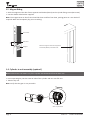
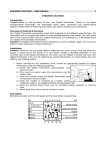
1.3 Prior to installation
Warning: Do not attempt to operate the unit until assembled into the door
• Press & hold the knob (1) and turn it slightly (2) until the cylinder cam is no longer protruding from the side
of the cylinder body (see illustration).
1.4 Cylinder & Unit installation
• Insert the cylinder (with base plate & knob) from the internal side of the door.
• Once the cylinder is correctly aligned in the door secure the cylinder in place using the M5 screw.
• Do not over tighten the screw or use power tools.
Note: Do not hammer (or otherwise force) either the cylinder or knob when inserting into the door.
• Turn the knob back to zero position. Knob marks are pointing up.
Note: The knob will jump out when returned to zero position.
Zero position
ENTR™ User Manual
Page 5
1.5 Magnet fitting
• Stick the magnet to the door frame opposite and below (20mm) to the cylinder fixing screw (M5 screw).
• Use the double sided sticker supplied.
Note: The magnet area on door frame should be clean and free from dust, peeling paint etc. Use alcohol if
required. Wait until completely dry prior to sticking.
Door frame
20
M5 Screw
Magnet
Stick the magnet to door frame opposite
and below (20mm) to the M5 screw
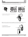
1.6 Cylinder to unit assembly (optional)
Note: Follow those instructions only if the cylinder was dismantled from the door unit.
• Insert operating key into the external side of the cylinder and turn one full turn.
• Take the key out.
Note: Verify that the gear is not pressed in.
Gear not pressed in
Page 6
ENTR™ User Manual
• Verify the knob is in zero position. Knob marks are pointing up (see page 5).
• Verify that the rectangle driver (cylinder) is in the same direction as the knob rectangle bore. If required turn
the rectangle driver (cylinder) until it is in the same direction (see illustration below).
Knob back view
Knob back view
Driver
• Assemble the cylinder into the door unit (base plate & knob).
• Tighten cylinder mounting screw.
Mounting screw
Note: Verify that the cylinder and the knob are engaged. Press the knob and try to turn. If the knob can not be
pressed or turned, disassemble the cylinder, adjust the cylinder projecting rectangle and reassemble.
• Connect data cable plug
• Assemble Electrical unit as illustrated
• Tighten electrical unit panel screw
Data cable
1
2
ENTR™ User Manual
Page 7
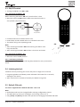
2. ENTR™ description
2.1 ENTR™ description
Knob
Indications
Touchpad
ON/OFF switch
2.2 Indications
Page 8
Mute (Green)
Manual Mode (Green)
OK (Green)
Door not closed (Red)
Battery status (Green/Red)
Error (Red)
ENTR™ User Manual
2.3 ON/OFF switch
• Turning the ENTR™ lock ON or OFF.
2.3.1 Switching the ENTR™ ON
Before switching the ENTR™ ON verify that the door is shut.
• Move the switch to ON position. Make sure that the knob is in
zero position (see illustration).
Zero position
• Function and numeric buttons blinks once.
• Hazard beep sound emitted and error indication blinks once.
• The ENTR™ will go into operating mode.
Note:
• After switching the ENTR™ ON avoid touching the ENTR™ until
beep sound ends.
• After switching the ENTR™ ON the door is shut but not locked.
ON
•
OFF
2.3.2 Switching the ENTR™ OFF
• Move the switch to OFF position.
2.3.3 Low battery indication
Warning signal blinking rapidly and long beep emitted on every lock/unlock
action.
2.4 Initiating the lock
Initiate the lock by touching the screen with palm or fingers for 3 seconds.
• Programing buttons and battery status indication illuminates for 15 seconds,
waiting for user action.
• After a period of 15 seconds of inactivity the ENTR™ will go idle.
2.5 Default PIN code
The lock is supplied with a default PIN code: 1 2 3 4 5 #
Note:
• Default PIN code must be changed before starting configuration process.
• The PIN code may consist of 4-10 digits, each having a value of 1-5.
• Only [Code] and [Mute] functions will operate until changing the default PIN code.
ENTR™ User Manual
Page 9
3. Operation
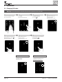
3.1 Changing PIN code
Warning: Do not attempt to operate the unit until assembled into the door.
1
Touch screen with palm or fingers
for 3 seconds to active
5
Numeric buttons illuminated Enter
[New PIN code] (4-10 digits)
[#]
For example: 1231234#
2
Press [Code]
Numeric buttons illuminated
6
[OK] indication blinks once
1 long beep emitted
Illuminated buttons turns off
Pin codes match
[OK] indication illuminated
2 short beep emitted
New PIN code is set
Page 10
3
4
Type [Default PIN code]
(1 2 3 4 5)
[#]
[OK] indication blinks once
1 long beep emitted
Illuminated buttons turn off
7
Numeric buttons illuminated Reenter
[New PIN code]
[#]
For example: 1231234#
Pin codes do not match
[Error] indication illuminated
2 long Beeps emitted for 1 second
ENTR™ goes to menu mode
Start the process from stage 1
ENTR™ User Manual
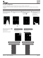
3.2 Door configuration
The Door Configuration process will determine the lock and door characteristics.
This process is done once after completing the installation process of the lock. It will take 15-20 seconds to
complete.
Important: Verify that the door is shut and no key is inserted into the cylinder prior to any configuration process
1
2
Touch screen with palm or fingers
for 3 seconds to active
3
Press [Cfg]
Numeric buttons illuminated
Type [Pin code]
[#]
1 long beep emitted
Configuration OK
5
The lock will carry out the
configuration process.
It will take 15-20 seconds to complete
Hold the door shut to avoid opening
4
[OK] Indication blinks once
2 short beeps emitted
Illuminated buttons turn off
Numeric buttons blinks
Press [1] or [3] to configure cylinder
side (see illustration)
Press [1] for left hand door
Press [3] for right hand door
Configuration failed
[Error] indication illuminated
3 short beeps emitted
ENTR™ goes to menu mode
Start the process from stage 1
ENTR™ on left side of the door
ENTR™ on right side of the door
Press [1]
Press [3]
ENTR™ User Manual
Page 11
3.3 Pairing remote control
1
2
3
Press [Add]
Touch screen with palm or fingers
for 3 seconds to active
Pairing OK
5
Press the remote control button
4
Press [1] to add remote control
Illuminated buttons turn off
[OK] indication blinks for 15 Seconds
waiting for remote control unit
Numeric buttons illuminated
Type [Pin code]
[#]
Numeric buttons blinking
[OK] indication blinks once
2 short beeps emitted
Remote control unit added
Pairing failed
[OK] indication blinks for 15 seconds
No beeps emitted
Start the process from stage 1
Remote
control
button
Notes:
• To add more remote control units repeat this procedure
• A remote control unit can be paired with only one single door unit
• It is possible to add up to 20 remote control units
• Only authorized dealer can reset a paired remote
Page 12
ENTR™ User Manual
3.4 Deleting remote control
The Deleting remote control process will delete all remote control units defined in the system.
1
Touch screen with palm or fingers
for 3 seconds to active
2
3
Press [Del]
Numeric buttons illuminated
5
Press [Del] to confirm
Type [Pin code]
[#]
1 long beep emitted
4
[Del] blinks for 30 seconds
Deletion accomplished
[OK] indication blinks once
2 short beeps emitted
Illuminated buttons turn off
Note: Wall reader and smartphone connected to the ENTR™ lock will not be deleted
ENTR™ User Manual
Page 13
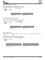
3.5 Setting the sound signal
Toggling the sound signal OFF or ON
1
Touch screen with palm or fingers
for 3 seconds to active
2
Press [Mute]
3
[Mute] indication illuminated.
Sound signal is off
Notes:
• Setting the ENTR™ lock sound to OFF will mute the lock & unlock sounds and the open door hazard signal.
It will not mute the touchpad, mechanical override and low voltage sounds
• Follow the same procedure to toggle the sound [ON]
3.6 Setting locking mode
Toggling Automatic to Manual locking mode
1
Touch screen with palm or fingers
for 3 seconds to active
2
Press [M A]
3
Type [Pin code]
4
[#]
[Manual] indication illuminated
Notes:
• Setting the ENTR™ lock to [Manual] will disable the automatic locking
• Follow the same procedure to set the ENTR™ lock to [Automatic]
Page 14
ENTR™ User Manual
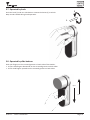
3.7 Operated by knob
2
Push the knob (1) and turn Clockwise or Counterclockwise (2) to unlock.
Beep sound emitted during knob operation.
1
3.8 Operated by slide buttons
Slide your fingers on the recessed grooves on both sides of the ENTR™:
• To open slide fingers downwards on the recessed grooves on both sides.
• To lock slide fingers upwards on the recessed grooves on both sides.
Open
Lock
ENTR™ User Manual
Page 15
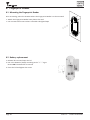
4. Touchpad Reader
4.1 Mounting the Touchpad Reader
Prior to starting, select the location where the Tochpad Reader is to be mounted.
• Attach the Touchpad Reader base plate to the wall.
• Use 4 screws and screw anchors or double sided glued tape.
4.2 Battery replacement
1.Release lid screw and open the lid
2.Put in the batteries (2xAA) according to the "+" "-" signs
3.Close the lid and tighten the screw
Notes:
• After inserting the batteries the Touchpad Reader will turn
on automatically
• A short beep sound emitted and Green [OK] indication
illuminated for 2 seconds.
Important: Do not touch the Touchpad during the self test
procedure and until the lights are off.
4.2.1 Low battery indication
Red warning signal blinking rapidly and long beep emitted on
every lock/unlock action.
Page 16
ENTR™ User Manual
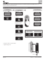
5. Touchpad Reader operation
5.1 Operation
To turn the Touchpad Reader ON press [#] for 5 seconds. The reader will perform a self test followed by
series of beeps. Led blinks Green, Red, Blue.
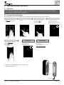
5.2 Pairing Touchpad Reader
This procedure is done via the ENTR™ lock. See also Pairing Remote Control unit procedure.
1
Touch ENTR™ lock screen with palm
or fingers for 3 seconds to active
2
3
Press [Add]
5
Touch the Touchpad Reader screen
with palm or fingers
Press [77]
[#]
Blue LED blinking rapidly
4
Numeric buttons illuminated
Type [Pin code]
[#]
Numeric buttons blinking
Pairing OK
[OK] indication blinks once
2 short beeps emitted
Touchpad Reader added
Press [1] to add Touchpad
Illuminated buttons turn off
[OK] indication blinks for 15 seconds
waiting for the Touchpad
Pairing failed
[OK] indication blinks for 15 seconds
No beeps emitted
In wall reader: Green LED illuminated
and 2 beeps emitted
Start the process from stage 1
• Hang the Touchpad Reader on the base plate.
• Tighten fixing screw.
Fixing screw
ENTR™ User Manual
Page 17
5.3 Touchpad Reader master PIN code
1
2
3
Enter [New master PIN code]
(4-10 digits)
[#]
For example: 1231234#
Touch screen with palm or fingers
Press [11]
[#]
Reenter:
[New master PIN code]
Master PIN code added
[#]
Master PIN code not added
Green [OK] illuminated for 1 second
2 short beeps emitted
Red [Error] illuminated for 1 second
1 long beep emitted
5.4 Menu mode
Entering menu mode: Press [*]
[Master PIN code]
[#]
5.5 Adding personal user code (up to 20 different codes)
1
2
3
Enter [Personal PIN code]
(4-10 digits)
[#]
For example: 1231234#
Touch Touchpad Reader screen with
palm or fingers
Press [*]
[Master PIN code]
[#]
Press [11]
[#]
Retype:
[Personal PIN code]
Pin code added
[#]
Pin code not added
Green [OK] illuminated for 1 second
2 short beeps emitted
Red [Error] illuminated for 1 second
1 long beep emitted
5.6 Open door
1
Touch Touchpad Reader screen with palm
or fingers
Not opening
2
Press [Personal PIN code]
[#]
Red [Error] illuminated for 1 second
1 long beep emitted
5.7 Lock door
1
Touch Touchpad Reader screen with palm
or fingers
Page 18
Not locking
2
Press [1]
[#]
Red [Error] illuminated for 1 second
1 long beep emitted
ENTR™ User Manual
5.8 Delete personal user code
1
2
Touch Touchpad Reader screen with palm
or fingers
Press [*]
[Master PIN code]
[#]
Press [33]
[#]
For deletion enter:
[Personal PIN code]
[#]
Personal code deleted
Personal code not deleted
Green [OK] illuminated for 1 second
2 short beeps emitted
Red [Error] illuminated for 1 second
1 long beep emitted
5.9 Delete all personal user codes
1
2
Touch Touchpad Reader screen with palm
or fingers
Press [*]
[Master PIN code]
[#]
Press [22]
[#]
Enter [Master PIN code]
[#]
Reenter: [Master PIN code]
[#]
Personal PIN codes deleted
Personal PIN codes not deleted
Green [OK] illuminated for 1 second
2 short beeps emitted
Red [Error] illuminated for 1 second
1 long beep emitted
Note: Master PIN code can not be deleted
5.10 Factory reset
The reset action will delete all PIN codes (master and personal) and will cut off the Touchpad Reader from the
ENTR™ lock.
1
2
Touch Touchpad Reader screen with palm
or fingers
Press [*]
[Master PIN code]
[#]
Press [99]
[#]
Enter [Master PIN code]
Personal and master PIN codes deleted
Green [OK] illuminated for 1 second
2 short beeps emitted
Device performing self test & is factory reset
ENTR™ User Manual
[#]
Personal and master PIN codes not deleted
Red [Error] illuminated for 1 second
1 long beep emitted
Page 19
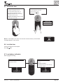
6. Fingerprint Reader
6.1 Mounting the Fingerprint Reader
Prior to starting, select the location where the Fingerprint Reader is to be mounted.
• Attach the Fingerprint Reader base plate to the wall
• Use 4 screws and screw anchors or double sided glued tape
6.2 Battery replacement
1.Release lid screw and open the lid
2.Put in the batteries (2xAA) according to the "+" "-" signs
Green LED illuminated for 2 seconds
3.Close the lid and tighten the screw
Page 20
ENTR™ User Manual
6.3 Initial configuration
1.Touch [#] for 3 seconds. The reader will perform self calibration followed by a series of beeps and blinking
LEDs. At the end of the calibration the screen will display:
SUCCESS
CALIBRATE
2.Adjust Date & Time.
--/--/--
DEVICE
--/--
[OK]
DATE/TIME
11
12
2
3
8
4
7
DD/MM/YY
15/03/15
[OK]
1
10
9
6
5
hh:mm
Enter Date
11
12
1
10
2
9
3
8
4
7
6
5
11:00
Enter Time
6.4 Pairing fingerprint reader
This procedure is done via the ENTR™ lock. See also Pairing Touchpad Reader procedure.
1
2
Touch ENTR™ lock screen with palm
or fingers for 3 seconds to active
3
Press [Add]
5
Pairing OK
Touch Fingerprint Reader screen
2 short beeps emitted
Press [OK] for YES or [*] to cancel
4
Numeric buttons illuminated
Type [Pin code]
[#]
Numeric buttons blinking
Pairing failed
[OK] indication blinks once
2 short beeps emitted
Fingerprint Reader added
1 long beep emitted
Red LED illuminated for 2 seconds
MATCH LOCK?
LOCK
FAILED
*-NO OK-YES
MATCHED
MATCH
Note: At the end of the initial matching
process a short warning will be displayed.
ENTR™ User Manual
Press [1] to add the reader
Illuminated buttons turn off
[OK] indication blinks for 15
seconds waiting for the reader
WARNING
NO USERS
Page 21
Setting a Master User require both fingerprint & code. It is possible to add up to two Master Users. it is
possible to add up to two master users.
Note: At any stage press and hold the [*] key to move to standby state
6. Add Master
Type in [Master name]
[OK]
8. Set PIN code
7. Set finger
Blue LED illuminates
ADD USER
MASTERNAME
ADD USER
SET FINGER
JOHN
SET CODE
Press [OK]
MASTER #01
Press [OK]
Green LED blinking
ENTER CODE
ENTER CODE
******
SWIPE
JOHN
4-10 digits
1st FINGER
Type in [PIN code] (4 to 10 digits)
Swipe 1st finger several times
over fingerprint scanner until two
confirmation beeps emitted
RETYPE CODE
******
SUCCESS
4-10 digits
Retype [PIN code] (4 to 10 digits)
1st FINGER
Green LED blinking
SWIPE
2nd FINGER
Swipe 2nd finger several times
over fingerprint scanner until two
confirmation beeps emitted
Matched codes
Mismatched codes
SUCCESS
FAILED
SET CODE
INVALID
SUCCESS
2nd FINGER
• Hang the reader on the base plate.
• Tighten fixing screw.
Fixing screw
Page 22
ENTR™ User Manual
6.5 Unlock the door
OPTION 1:
Place finger on fingerprint scanner.
OPTION 2:
Touch the Fingerprint Touchpad
Short beep emitted & white LED is on.
Swipe finger over fingerprint scanner
Fingerprint authorized: Blue LED blinking
and unlock command is sent.
Fingerprint not authorized: Red LED is ON.
The device goes to standby.
Screen shows user code
Enter your code
[OK]
USER CODE
23:49 03/01
Note: In case ENTR™ lock hasn't succeed to unlock the door, unlock failed
message appear on the screen.
FAILED
UNLOCK
6.6 Lock the door
Touch the Fingerprint Touchpad
Press [#] [1]
6.7 Low battery indication
Warning signal blinking
Fingerprint Reader low battery indication
Red LED illuminate for 1s after wake-up
2 long beeps emitted
BATTERY LOW
ENTR™ User Manual
Door Unit low battery indication
Low battery: Red LED illuminate for 1s after
wake-up
Extremely low battery:
Red LED illuminate for 1s after wake-up
2 long beeps emitted
BATTERY LOW
Page 23
6.8 Setting menu
USER CODE
Touch screen
MASTER CODE
SETTING
******
USERS
23:49 03/01
23:49 03/01
Press [*]
Enter [Master PIN code]
[OK] or
swipe finger over fingerprint scanner
6.9 Add user
The unit allows adding up to 20 users. For each user two different fingerprints and one PIN code. Use different user name
for each user.
1
2
3
SETTING
USERS
USERS
ADD USER
4
2nd MASTER?
USERNAME
JENNIFER
*-NO OK-YES
Press [OK]
Press [OK]
Choose [OK] to add 2nd Master
User or [*] to add a user.
Note: This screen will not appear
if two Master Users are defined.
Type [USER NAME]
[OK]
User name added
User name exist
USER #08
USERNAME
JENNIFER
User name added
5
1st finger added
6
ADD USER
EXIST
Same user name.
Choose different user name
2nd finger added
7
SWIPE
SUCCESS
SWIPE
SUCCESS
1st FINGER
1st FINGER
2nd FINGER
2nd FINGER
SET FINGER
Press [OK]
8
Swipe 1st finger several times
over fingerprint scanner until two
confirmation beeps emitted
9
ADD USER
SET CODE
*-NO OK-YES
Press [OK] for YES or [*] for NO
Page 24
Swipe 2nd finger several times
over fingerprint scanner until two
confirmation beeps emitted
10
ENTER CODE
ENTER CODE
******
4-10 digits
Type [CODE]
[OK]
RETYPE CODE
Matched codes
Mismatched
codes
SUCCESS
FAILED
******
4-10 digits
Retype [CODE]
SET CODE
[OK]
INVALID
Process did not complete. All
data typed in will be erased from
memory.
ENTR™ User Manual
6.10 Delete user
USER CODE
Touch screen
1
MASTER CODE
SETTING
******
USERS
23:49 03/01
23:49 03/01
Press [*]
Enter [Master PIN code]
[OK] or
swipe finger over fingerprint scanner
2
3
SETTING
USERS
DELETE USER
USERS
DELETE USER
JENNIFER
Press [OK]
Use [8▼] or [2▲] to select:
[DELETE USER]
[OK]
User deleted
4
SURE?
*-NO OK-YES
*-NO OK-YES
Press [OK]
Confirm deletion
DELETED
JENNIFER
Two beeps emitted
Green LED illuminates
Note: First Master User cant be deleted unless doing factory reset.
6.11 Delete all users
USER CODE
Touch screen
1
SETTING
******
USERS
23:49 03/01
23:49 03/01
Press [*]
Enter [Master PIN code]
[OK] or
swipe finger over fingerprint scanner
2
3
SETTING
USERS
USERS
DELETE ALL
Press [OK]
MASTER CODE
Use [8▼] or [2▲] to select:
[DELETE ALL]
[OK]
All users deleted
4
DELETE ALL?
SURE?
SUCCESS
*-NO OK-YES
*-NO OK-YES
DELETED ALL
Press [OK]
Press [OK]
Two beeps emitted
Green LED illuminates
6.12 Factory reset
Warning: The factory reset action will delete all information stored in the memory, users and matched lock.
USER CODE
Touch screen
23:49 03/01
Press [*]
1
2
SETTING
******
USERS
23:49 03/01
Enter [Master PIN code]
[OK] or
swipe finger over fingerprint scanner
DEVICE
DEVICE
FACTORY
Use [8▼] or [2▲] to select:
[FACTORY]
[OK]
ENTR™ User Manual
Factory reset
4
3
SETTING
Use [8▼] or [2▲] to select:
[DEVICE]
[OK]
MASTER CODE
RESET?
SURE?
SUCCESS
*-NO OK-YES
*-NO OK-YES
FACTORY
Press [OK]
Press [OK]
Two beeps emitted
Green LED illuminates
Page 25
7. Smartphone App
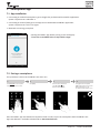
7.1 App installation
• Connecting an Android smartphone: go to Google Play to download the ENTR™ application.
System requirements: Android 4.4
• Connecting an iPhone/iPad: go to the App store to download the ENTR™ application.
System requirements: iOS 7.0 or higher
• Bluetooth low energy compliant
Starting the ENTR™ App before pairing a lock will display:
"There are no available locks or keys within range".
7.2 Pairing a smartphone
This procedure is done via the ENTR™ lock door unit.
1
Touch Door Unit screen with palm
or fingers for 3 seconds to active
2
Press [Add]
3
Numeric buttons illuminated
Type [Pin code]
[#]
Numeric buttons blinking
4
Press [2] to add a smartphone
[OK] indication blinks for 3 Seconds
Illuminated buttons turn off
The ENTR™ will be visible for 5 min
Start the ENTR™ App and follow the steps described in order to pair the smartphone with the ENTR™ lock
App User Manual is available to download at: www.entrlock.com
Page 26
ENTR™ User Manual
8. Remote control battery change
8.1 Battery removal
a. Release the lid by safely inserting a tool into the notch (1) and pressing the lid clasp (2).
Notch
1
2
Clasp
b.Take out the push button and the intermediate part
c. Take out the electronic board with the battery and take the battery out.
ENTR™ User Manual
Page 27
8.2 Battery insertion
a. Insert the battery (CR2032) according to the "+" "-" signs (1)
b.Insert the electronic board with the battery into the remote housing (2)
2
1
c. Assemble the intermediate part and the push button over the electronic board
d.Place the lid and press until the clasp will pop into the notch
Clasp
Page 28
ENTR™ User Manual
9. Troubleshooting
9.1 Limitations and external influences
1.Door position sensor might be influenced by external electromagnetic interference.
2.After mechanical key operation, the user should unlock and lock the unit electronically.
9.2 Cases
Symptom
Corrective action
Failure to pair a credential
1. Repeat the process closer to the door unit
2. Turn the door unit OFF and back ON
3. Smartphone - reboot the smartphone and the
Door Unit
Door unit beeps constantly
Place the knob in zero position
Cant connect mobile App with the ENTR™
Other phone user is already connected to the ENTR™.
Only one smartphone can connect to the ENTR™ at
the same time
2 sets of double long beeps in every lock or
unlock operation
Low battery indication; Charge the Door Unit
ENTR™ unlocks the door instead of locking it
Repeat door configuration process.
Define [1] for left side lock or [3] for right side lock
See page 11 - Door configuration
Bolts are going out when the door is open
1. Check if the magnet exists
2. Unlock the door using the sliders, quickly shut the
door and lock it using the sliders
ENTR™ doesn't lock automatically
After 5 minutes that the door is open
Close the door and lock using credential or slide up
on sliders
Automatic locking might be effected by
external electro-magnetic fields that results in
wrong reading of door positioning. That may
cause the door to remain unlocked.
Sliders doesn't response as expected
Touch panel doesn't response as expected
Latch isn't pulled (high friction on the
bolts & latch)
Turn OFF the unit, wait 3 seconds and turn it back ON.
Avoid touching the unit until you hear power up beeps
1. Pull/push the door toward the frame
2. Consult your installer to adjust the door or lock case
Error sound emitted during lock / unlock
action
Placing a code in the Touchpad Reader ends in
wrong code, even if the code is correct
The specific code already exists
Operating key will not operate the cylinder
Push the key towards the cylinder and try to operate.
If not turning call a locksmith
ENTR™ User Manual
Page 29
LIMITED WARRANTY
Mul-T-Lock® hereby warrants, to the end user ("Purchaser") who purchased the genuine Mul-T-Lock® product
(“Product"), from an authorized Mul-T-Lock® dealer (“Dealer”), that the Product will be free from defects in
materials and workmanship ("Defects"), for a period of one year from the date the Product was purchased from
Mul-T-Lock®'s authorized dealer. Subject to the terms and conditions indicated below, Mul-T-Lock® will repair or
replace such Product or part thereof which, upon inspection by Mul-T-Lock®'s authorized dealer, is found to be
defective, despite the Product not having been subjected to Improper Activity (as defined below).
Improper Activity shall render this warranty void. “Improper Activity” includes any and all of the following: installation
by anyone other than a Dealer: improper installation; use/operation/maintenance other than in accordance with
Mul-T-Lock®’s instructions and requirements (as directed below); tampering by Purchaser; neglect; damage by
the application of force; bending; breaks; cracks; scratches; any other act of vandalism; repair or alteration by
anyone other than a Dealer: use of keys, key blanks, cylinders, locks, approved batteries, accessories and/or
other components that are not suitable and genuine Mul-T-Lock® products; all the foregoing as determined by
Mul-T-Lock®, in its sole judgment.
Some basic instructions and recommendations for correct use of the Product are shown overleaf.
Mul-T-Lock®’s sole obligation under this limited warranty is to repair or replace, at Mul-T-Lock®'s sole discretion,
at the venue of a Dealer, any Product and/or Product component found by Mul-T-Lock® to have Defects. This
limited warranty does not grant any other rights or give rise to any other obligation, or absolve Purchaser of the
responsibility to employ any other suitable measures, by whatever means, including insurance, against the risk of
personal injury or damage to property. This limited warranty relate to product's defects only. Mul-T-Lock® shall be
liable, in any event, for any labour costs associated with the product and its installation process.
In order to facilitate the warranty service and enable Mul-T-Lock® to determine entitlement under this warranty,
Purchaser must first return the Product, with proof of purchase from a Dealer, to Mul-T-Lock®, either directly, or
through the Dealer from whom Purchaser purchased the Product. All shipping, handling, travel, service call and/
or other incidental and/or related charges are fully payable by Purchaser only and are not included in this limited
warranty.
THE USE OF OTHER THAN SUITABLE, GENUINE MUL-T-LOCK® COMPONENTS MAY CAUSE SEVERE DAMAGE TO
THE PRODUCT, AND WILL VOID THIS LIMITED WARRANTY. THIS LIMITED WARRANTY MAY NOT BE ASSIGNED OR
OTHERWISE TRANSFERRED IN ANY WAY AND MAY NOT BE EXTENDED, ALTERED OR VARIED.
TO THE FULLEST EXTENT ALLOWABLE BY THE LAWS APPLYING HERETO, THIS LIMITED WARRANTY IS IN LIEU OF
ANY OTHER WARRANTIES, EITHER EXPRESS OR IMPLIED, INCLUDING BUT NOT LIMITED TO ANY WARRANTIES
OF MERCHANTABILITY OR FITNESS FOR A PARTICULAR PURPOSE, ALL OF WHICH ARE EXPRESSLY EXCLUDED
AND DISCLAIMED. MUL-T-LOCK® WILL NOT BE LIABLE FOR LOSS OF PROFITS, ANY SPECIAL, INCIDENTAL, OR
CONSEQUENTIAL DAMAGES, WHICH PURCHASER MAY SUSTAIN, OR PUNITIVE DAMAGES, EVEN IN THE EVENT OF
NOTICE OF THE POSSIBILITY OF SUCH DAMAGES.
Some Basic Instructions and Requirements for Correct Use of ENTR™ Products
Protection of Keys:
• Keys should be used only for their original purpose, of operating the corresponding cylinder.
• Your key carries a code. Make sure you keep it concealed.
Page 30
ENTR™ User Manual
• Only genuine Mul-T-Lock® key blanks should be used.
• Duplicate keys must be performed by an authorized Mul-T-Lock® locksmith on Mul-T-Lock®'s key cutting
machine.
• Keys must be inspected periodically and must be replaced when show physical wear.
Cylinders:
•
•
•
•
•
Installation must be performed by an authorized Mul-T-Lock® dealer only.
Cylinders must not be submerged in water, or exposed to any chemical wash, or be painted.
Protect the cylinder from dirt & dust.
Protect your cylinder from exposure to extreme temperatures. (External -20 C to +80C, Internal -10C to +50C)
The cylinder’s keyway should be lubricated at least once per year (preferably using lubricants authorized by
Mul-T-Lock®, or light machinery oil). In any heavy use environments, extreme weather conditions, lubrication
must be conducted every three months.
Mobile phones
LEGAL NOTICES
ENTR™ warranty should not cover any problem related with end user mobile phone/smartphone or its
operation system, by connecting to ENTR™ lock or installing ENTR™ application. For any other limitation please
refer to End User licence agreement.
Items excluded / limited from this warranty
•
•
•
•
Screws
Normal wear and tear
Cleaning with cleaning detergents
Warranty for ENTR's Main battery is limited for 1 year
Trademarks
Mul-T-Lock® and ENTR™ are trademarks/trade names belonging to Mul-T-Lock® Ltd. No unauthorised use may
be made of these trademarks.
No Insurance
No security product can ever guarantee the safety of assets. The ENTR™ product is by no means a substitute for
suitable insurance coverage protecting against loss or damage of your property. Mul-T-Lock® is not an insurance
company and does not provide insurance services of any kind.
External Influences
• Services are subject to various external influences, outside our control, such as satellites and cellular or
other communications networks, and may also be influenced by weather conditions, frequency jamming/
interference, improper use or activity, interference, vandalism, destruction etc.
• Services may also be adversely affected, or rendered impossible when the ENTR™ product is located in places
where a signal may not be available - for example, a garage, parking lot, tunnel or other such location.
• The fingerprint sensor may not work for certain members of the population, for physiological reasons
Limitations of Services and Liability
The Services will not always provide an accurate picture of whether or not assets have been subject to
unauthorized access - for example, if the ENTR™ product is accessed using the original key or a duplicate key.
• Proper functioning of the ENTR™ product may be impaired if the ENTR™ product is not installed and
maintained properly, in accordance with the instructions provided with the ENTR™ product. Installation and/
or disassembly must be carried out only by authorised ENTR™ installation personnel.
ENTR™ User Manual
Page 31