1
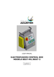
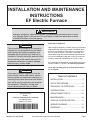
INSTALLATION AND MAINTENANCE
INSTRUCTIONS
EF Electric Furnace
WARNING
Improper installation, adjustment, service, or maintenance can cause injury or property damage. Refer to this manual. For assistance or additional information, consult
a qualified installer or service agency.
WARNING
The information contained in this manual is
intended for use by qualified service technicians familiar with safety procedures and
equipped with the proper tools and test instruments. Failure to carefully read and follow
all instructions in this manual can result in
equipment malfunction, property damage,
personal injury, and/or death.
WARNING
Disconnect all power supplies to both the
indoor blower section and outdoor section
before making any electrical connections or
servicing the system. More than one disconnect switch may be required to de-energize
the equipment. Hazardous voltage can
cause severe personal injury or death.
Inspection of Shipment
Upon receipt of equipment, carefully inspect it for possible
shipping damage. If damage is found, it should be noted
on the carrier’s freight bill. Take special care to examine
the unit inside the carton if the carton is damaged. Any
concealed damage discovered should be reported to the
last carrier immediately, preferably in writing, and should
include a request for inspection by the carrier’s agent.
If any damages are discovered and reported to the carrier
DO NOT INSTALL THE UNIT, as claim may be denied.
Check the unit rating plate to confirm specifications
are as ordered.
TABLE OF CONTENTS
INSTALLATION....................................... 2
SETUP PROCEDURE ........................... 6
SEQUENCE OF OPERATION ............... 8
SYSTEM CHECK ................................... 9
Manufactured By
A.A.C.
A Lennox International Inc. Company
421 Monroe Street
Bellevue, OH 44811
*44876D006*
# 44876D006/ 44876D006
0650329-50
REPLACEMENT PARTS ...................... 10
MAINTENANCE ................................... 10
AIRFLOW CONFIGURATIONS ............ 11
WIRING DIAGRAMS ............................ 12
WARRANTY ......................................... 15
Save these instructions for future reference
Page 1
INSTALLATION
Knockouts are provided for electrical power wiring entrance.
This EF electric furnace is designed for ease of installation
featuring horizontal, upflow, and downflow (counterflow)
applications. The units are shipped from the factory
completely assembled. Accessories may also be ordered
as field-installed items. All models are designed for
indoor installations only.
When used on cooling applications, excessive sweating
may occur when unit is installed in a very humid space.
Read the entire instruction manual before starting the
installation. Several of the installation steps can be done
prior to setting the unit in place and doing this can save
time and simplify installation. Do not remove the cabinet
knockouts until it has been determined which knockouts will need to be removed for the installation.
Determining which knockouts to remove will depend on
application and in some cases preference.
These instructions are intended to be a general
guideline and do not supersede any local or national
codes. Installation must conform with the local
building codes and with the latest editions of the
National Electric Code or Canadian Electric Code.
Improper installations not following these instructions can
result in unsatisfactory operation and/or dangerous
conditions and may void the unit warranty.
If installed in an unconditioned space, sealant should be
applied around the power wires, control wires, refrigerant
tubing, and condensate lines where they enter the cabinet.
Power wires should be sealed on the inside where they
exit the conduit opening. Sealant is required to prevent air
leakage into and condensate from forming inside the unit,
control box, and on electrical controls.
The unit must be installed in such a way as to allow free
access to the coil compartment and blower/control
compartment.
The unit must be installed in a level position to ensure
proper condensate drainage. Make sure unit is level in
both directions within 1/8".
Units with circuit breakers installed in the vertical
position must have breaker switch position “ON” in
the up position and switch position “OFF” in the down
position. This is necessary to meet agency certification
and National Electric Codes requirements.
Conversion to Vertical Downflow
General Information
The EF electric furnace may be used with optional mating
furnace coil cabinets in upflow, counterflow, or horizontal
applications (see AIRFLOW CONFIGURATIONS on page 11
for acceptable system configurations). Tie-plates and the
necessary hardware are packaged with the blower sections to
connect the furnace and coil section cabinets together.
To avoid drain pan overflow of coil cabinets, the web
must be removed from inside any threaded drain pan
hole to which a drain line is to be connected. Use care
when removing the web so as to not damage the coil.
To avoid property damage caused by condensate drain
blockage, install a field fabricated auxiliary drain pan with
a separate drain line to the outside under any indoor
electric furnace where condensate overflow could occur. If
local building codes apply, install per those codes.
Select the best position which suits the installation site
conditions. Take into consideration required clearances,
space, routing requirements for refrigerant line, condensate disposal, filters, ductwork, wiring, and accessibility for
service. Refer to the unit specifications sheet and the unit
rating plate for specific information.
These electric furnaces are completely factory assembled
and all components are performance tested. Each unit
consists of a blower assembly, optional refrigerant coil,
and controls, in an insulated galvanized factory finished
enclosure, and may also include electric heat as specified.
Page 2
The EF furnace may be converted for vertical downflow
applications. The circuit breaker(s) must be rotated 180°.
To comply with certification and the National Electric
Code, units with circuit breakers installed in the
vertical position must have circuit breakers installed
so that the breaker switch “ON” position and marking
is up, and “OFF” position and marking is down.
All electric furnaces installed with a mating coil section
must follow the instructions listed below for proper condensate drainage. It is recommended that the auxiliary
drain be connected to a drain line for all units. If the
auxiliary drain is not connected, it must be plugged with
provided cap. For counterflow units, the auxiliary drain
must be connected and routed to a drain.
Horizontal Installations
Horizontal installations can be left or right hand. Adequate
support must be provided to insure cabinet integrity.
Ensure that there is adequate room to remove service and
access panels if installing in the horizontal position. Refer
to the air flow configuration drawings on page 11 for
correct horizontal coil installations.
Ductwork and Airflow
Maintain all required clearances to combustible
surfaces as stated on the unit rating plate.
# 44876D006
Supply and return ductwork must be adequately sized to
meet the system’s air requirements and static pressure
capabilities. Ductwork should be insulated with a minimum
of 1" thick insulation with a vapor barrier in conditioned
areas or 2" minimum in unconditioned areas. Connect
supply air duct to the flange on top of the unit. If an
isolation connector is used, it must be non-flammable.
Sheet metal ductwork run in unconditioned spaces must
be insulated and covered with a vapor barrier. Fibrous
ductwork may be used if constructed and installed in
accordance with SMACNA Construction Standard on
Fibrous Glass Ducts. Check local codes for requirements
on ductwork and insulation.
Duct system must be designed within the range of external static pressure the unit is designed to operate against.
It is important that the system airflow be adequate. Make
sure supply and return ductwork, grills, special filters,
accessories, etc. are accounted for in total resistance.
If an elbow is included in the plenum close to the unit,
it must not be smaller than the dimensions of the
supply duct flange on the unit.
Non-Ducted Return Closet Installation
The cabinet can be installed in a closet with a false bottom
to form a return air plenum or be installed with a return air
plenum under the unit. Louvers or return air grilles are
field supplied. Local codes may limit application of systems without a ducted return to single story buildings.
•
Install louvers in a closet. Use the free area of louver
or grille to determine the size opening required to
provide the free area for metal louvers or grilles.
•
If the free area is not known, assume a 25% free area
for wood or a 75% free area for metal louvers or grilles.
•
If the return air plenum is used, the return air grille
should be immediately in front of the opening in the
plenum to allow for the free flow of return air.
•
When not installed in front of the opening, there must
be adequate clearance around the unit to allow for the
free flow of return air.
Supply plenum is attached to the duct flanges supplied on
the unit around the blower outlet.
Supply plenum should be the same size as the flanged
opening provided around the blower outlet and should
extend ideally at least 3' from the unit before turning or
branching off plenum into duct runs. The plenum forms an
extension of the blower housing and minimizes air expansion losses from the blower.
Recommended Remote Filter Sizes
Nominal Tons
Air Conditioning
&
Nominal Air Flow
Square Inch Surface Area
&
Nominal Size
Minimum
Return Air
Free Area
Disposable Filters
Washable Filters
Up thru 2 Tons
800 - 900 CFM
432 Square Inches
20" x 25"
260 Square Inches
15" x 20"
260 Square Inches
2-1/2 Tons
900 - 1000 CFM
480 Square Inches
20" x 30"
288 Square Inches
14" x 25"
288 Square Inches
3 Tons
1300 - 1500 CFM
576 Square Inches
14" x 25" (2)
346 Square Inches
16" x 25"
346 Square Inches
3-1/2 Tons
1300 - 1500 CFM
672 Square Inches
16" x 25" (2)
404 Square Inches
20" x 25"
404 Square Inches
4 Tons
1500 - 1700 CFM
768 Square Inches
20" x 25" (2)
461 Square Inches
20" x 25"
461 Square Inches
5 Tons
1900 - 2100 CFM
960 Square Inches
20" x 30" (2)
576 Square Inches
24" x 25"
576 Square Inches
Table 1
# 44876D006
Page 3
Condensate Drain Connection
Do not operate unit without a drain trap. The condensate drain is on the negative pressure side of the
blower; therefore, air being pulled through the condensate line will prevent positive drainage without a
proper trap.
To avoid drain pan overflow, the web must be removed from inside any threaded drain pan hole to
which a drain line is to be connected. Use care when
removing the web so as to not damage the coil.
On horizontal units, the primary drain connection is flush
with the bottom of the inside of pan. Auxiliary connection
is raised above the bottom of the inside of the pan. Plastic
web covering 3/4" auxiliary connection must be broken out
if used. Do not get primary and auxiliary connections
interchanged.
•
Install a 2" trap in the primary drain line as close to the
unit as practical. Make sure that the top of the trap is
below connection to the drain pan to allow complete
drainage of pan.
•
Auxiliary drain (if used) should be run to a place where
it would be noticeable if it becomes operational. Occupant should be warned that a problem exists if water
should begin running from the auxiliary drain line.
•
Test condensate drain pan and drain line after installation is complete. Pour several quarts of water into
drain pan, enough to fill drain trap and line. Check to
make sure drain pan is draining completely, no leaks
are found in drain line fittings, and water is draining
from the termination of the primary drain line.
Typical Condensate Drain Connection
When making drain fitting connections to the drain pan,
hand tighten only. Overtightening the fittings can split
connections on the drain pan.
The unit is provided with 3/4" FPT condensate drain
connections.
•
•
•
Connect the drain lines to the appropriate drain pan
fittings.
Secondary drain connections should be connected to
a separate drainage system.
Install a trap in the drain line below the bottom of the
drain pan and pitch the drain lines down from the coil
at least 1/4" per foot of run. Horizontal runs over 15'
long must also have an anti-siphon air vent (stand
pipe), installed ahead of the horizontal run. An extremely long horizontal run may require an oversized
drain line to eliminate air trapping.
•
Route to the outside or to an appropriate drain. Check
local codes before connecting drain line to an existing
drainage system.
•
Insulate drain lines where sweating could cause water
damage.
•
The removal of cabinet knockouts required for drain
connections can be made much easier with the indoor
coil assembly removed from the cabinet.
•
Install drain lines so they do not block service access
to front of unit. A 24" clearance is required for filter,
coil, or blower removal and service access.
•
Make sure unit is level or pitched slightly toward
primary drain connection so that drain pan will empty
completely without water standing in pan.
Page 4
Unit
Drain Connection
1.00" Min.
12.00"
Max.
3.00" Min.
Positive Liquid Seal Required
Figure 1
CAUTION
A field fabricated auxiliary drain pan, with a
drain pipe to the outside of the building, is
required in all installations over a finished living
space or in any area that may be damaged by
overflow from the main drain pan. In some
localities, local codes may require an auxiliary
drain pan for any horizontal installation.
# 44876D006
Variable Speed Features
Electrical Wiring
WARNING
Turn off electric power at the fuse box or
service panel before making any electrical
connections and ensure a proper ground
connection is made before connecting line
voltage. Failure to do so can result in property damage, personal injury, or death.
All field wiring must be done in accordance with National
Electrical Code recommendations, local codes, and
applicable requirements of UL; or in accordance with the
Canadian Electrical Code, local codes, and CSA Standards. Power wiring, disconnecting means, and overcurrent protection are to be supplied by the installer. See
he unit rating plate for unit maximum over-current protection, minimum circuit ampacity, and operating voltage. The
power supply must be sized and protected according to
the specifications supplied. Use of multiple supply circuits
require grounding of each circuit to lug(s) provided in unit.
Use copper conductors only.
The unit must be grounded with separate ground
connector(s). See the electrical connection diagrams
beginning on page 12 for typical field wiring connection.
High voltage pigtail wiring connections are included in the
unit. For systems requiring additional electric heat, this
plug-in harness will be discarded and the high voltage
connection will be made on field wire points on the heater
kit. Low voltage control wiring are pigtail leads located
outside the cabinet and are color coded to match the
connection called out on the wiring schematic.
The EFV electric furnace is equipped with a variable
speed motor and will deliver a constant airflow within a
wide range of external static pressures. The variable
speed blower offers the following comfort features:
Soft Start
When called into operation, the variable speed motor will
slowly ramp up to normal operating speed. This eliminates
the noise and discomfort that results caused by the initial
blast of air encountered with standard electric furnaces. It
can take up to 7.5 minutes to reach normal operating speed.
Continuous Blower Operation
The comfort level of the living space can be enhanced when
using this feature by allowing continuous circulation of air in
between calls for cooling or heating. The circulation of air
occurs at 50% of the normal airflow rate (350 CFM minimum).
Reduced Airflow Operation
For situations where humidity control is a problem, the
variable speed motor can be enabled to operate at a 10%
reduction in the normal airflow rate. This can be achieved
by connecting to a standard humidity control that is
normally closed and opens on humidity rise.
These units are designed for operation with a 208-240 volt
single phase, 60 cycle, AC power supply. The units are
internally factory wired for 240 volt installation. If 208 volt
installation is desired, it will be necessary to change the
black transformer lead in the blower cabinet control box to
the 208V terminal on the transformer.
IMPORTANT: The variable speed motor in the EFV
electric furnace contains DC filter capacitors that will
cause a surge or inrush of current when power is
applied. Power is to remain applied to the motor
except during servicing. Remove AC power before
plugging or unplugging the input power to the motor.
Do not install blower relays that interrupt line voltage
to the motor.
# 44876D006
Page 5
SETUP PROCEDURE
Blower Performance Chart
PSC Motor
PSC Motor
For proper cooling operation, the airflow through the
indoor coil should be between 350 and 450 CFM per ton
(12,000 Btuh) of cooling capacity based on the rating of
the outdoor unit.
The cooling blower speed is factory configured to provide
correct airflow for an outdoor unit that matches the
maximum cooling capacity rating of the electric furnace. If
the outdoor unit is smaller than the maximum cooling
capacity rating for the electric furnace, the cooling blower
speed may need to be changed (see Table 2).
IMPORTANT: The cooling blower speed must be set to
provide a minimum of 350 CFM airflow per ton (12,000
Btuh) of outdoor cooling capacity.
CFM @ External Static
Pressure in. W.C.
Blower
Model
Speed
EFC08
EFC12
0.1
0.2
0.3 0.4
0.5 0.6
Low
583
563
557
541
522
473
Medium
862
855
834
794
748
677
High
1159 1096 1029 957
871
794
Low
838
746
699
827
808
778
Medium 1265 1255 1235 1215 1173 1118
High
1358 1340 1311 1282 1231 1179
Low
1161 1153 1138 1115 1091 1050
Changing Blower Speed
1. Disconnect all power supplies.
EFC16
2. Remove the electric furnace access panel.
3. Locate pin number 2 on the blower relay. Two black wires
are connected to this terminal pin. One connects to pin
number 5 on the blower relay and the other connects to
an inline splice connected to a red or black wire.
EFC20
Medium 1569 1541 1507 1460 1405 1341
High
1769 1735 1703 1626 1570 1489
Low
1632 1566 1581 1544 1482 1417
Medium 2163 2103 2058 2000 1947 1855
High
2398 2394 2266 2180 2109 2042
4. Remove the wire going to the 4-pin blower motor
connector from the splice.
Table 2
5. Connect the blower lead (Red - LO, Black - HI) to the
splice from the 4-pin blower motor connector.
Unused blower speeds are shipped from the
factory covered with a plastic cap. Remove the
cap from the new blower speed terminal and place
it over the factory-set blower terminal.
6. Replace electric furnace access panel.
7. Reconnect power.
Motor Board Taps and
Dehumidify Resistor
ADJUST
NORM
(+)
(–)
TEST
HEAT
COOL
A
B
C
D
A
B
C
D
Variable Speed Motor
D1
Locate the motor control board in the blower control box.
Set the HEAT and COOL CFM taps by moving the board
jumpers to the A, B, C, or D positions (see Figure 2)
based on the information found in the Application Table
on page 11. The ADJUST tap on the control board can be
used to raise or lower the table CFM’s. The (+) tap will
raise the table CFM by 10%, and the (–) tap will lower the
table CFM by 12%. IMPORTANT: When changing the
control taps, the high voltage must be off in order for
the new settings to take effect.
Page 6
DEHUMIDIFY
CUT TO ENABLE
Figure 2
This model is designed for use with heat pumps as
well as air conditioning systems. The motor control
board needs to sense a signal on the “O” thermostat
wire in order to use cooling delay timing. For a
# 44876D006
straight air conditioning system, connect the “O” wire
to the 24 volt “R” wire.
The motor control board that provides airflow selection also
features LED indicators that display operating mode, humidity
control, and airflow CFM. In addition, thermostat signals for
emergency heat (EM), aux. heat (W1), reversing valve (O),
compressor stage 1 (Y1), compressor stage 2 (Y2), and
blower (G) are all indicated by lit LED’s on this board. If a
humidistat is used, the dehumidify LED will light when the
humidistat opens and the motor runs at reduced airflow. The
control board also has a CFM LED that displays the operating
CFM. This red LED flashes once for each 100 CFM. For
example, if the operating CFM is 1200, the CFM LED will flash
12 times, then pause before repeating the 12-flash pattern.
Special note for units equipped with a humidistat: If using
a humidistat, the dehumidify resistor located on the bottom
right of the control board must be removed (see Figure 2).
The HUM terminal on the board must be connected to the
Normally Closed contact of the humidistat so that the board
senses an open circuit on high humidity.
Application Table
The versatility of the variable speed motor enables the
performance of the EFV electric furnace to be tailored to
the different modes of operation encountered in heating and
cooling. All EFV electric furnaces are capable of operation
at more than one nominal airflow rate. The operation of an
EFV blower at different airflow rates is determined by the
control board taps and the thermostat (see the Application
Table below). Before beginning the setup, become familiar
with the information found in this table.
The data in the application table is categorized by unit size
and mode of operation. Use the information provided to
determine the CFM taps needed for cooling and heating.
Variable Speed Motor Application Table
Control Board Taps
Thermostat
Model
COOL
Mode
HUM EM
W1
O
Y2/Y1
Cont. Blower
Cooling
EFV12SBA
X
**
Heating
X
Emer. Heat***
X
X
X
X
X
Cont. Blower
EFV16MBA
X
**
Heating
X
Emer. Heat***
X
X
Cont. Blower
EFV20LBA
X
**
Heating
X
X
X
C
D
A
B
C
D
400
350
1200 1000
800
600
1200 1000
800
600
***
***
1200 1100* 1100* 1100*
1200 1100* 1100* 1100*
500
***
***
***
***
***
900
700
600
500
1600 1400 1200 1000
1600 1400 1200 1000
***
X
Aux. Heat***
Emer. Heat***
600
***
X
X
X
B
CFM CFM CFM CFM CFM CFM CFM CFM
X
Aux. Heat***
Cooling
A
X
Aux. Heat***
Cooling
G
HEAT
X
X
X
***
***
***
1600 1400 1200* 1000*
1600 1400 1200* 1000*
***
***
***
***
900
800
700
600
1800 1600 1400 1200
1800 1600 1400 1200
***
***
***
***
1800 1600 1400 1200*
***
***
***
***
1800 1600 1400 1200*
NOTES:
*
This CFM is not approved for use with highest kW heater size.
**
Humidistat will reduce cooling air flow by 10% in high humidity.
*** Airflow is greater of COOL and HEAT when both electric heat and heat pump are operating.
ADJUST tap (+) will increase airflow by 10%, while tap (–) will decrease airflow by 12%.
ADJUST tap TEST will cause the motor to run at 70% of full airflow. Use this for troubleshooting only.
At the start of a call for cooling there is a short run at 82% of airflow for 7.5 minutes.
At the end of a call for cooling there is a blower delay of 1 minute.
Table 3
# 44876D006
Page 7
SEQUENCE OF OPERATION
Cooling (cooling only or heat pump)
transfer to the first stage heat on the thermostat. This will
allow the indoor blower to cycle on and off with the electric
heat when the fan switch is in the AUTO position.
Single Stage Cooling
For single stage cooling, Y1 and Y2 need to be jumpered.
When the thermostat calls for cooling, the circuit between R
and G is completed, and the blower relay is energized. The
Normally Open contacts close, causing the indoor blower
motor to operate. The circuit between R and Y is also
completed; this circuit closes the contactor in the outdoor
unit starting the compressor and outdoor fan motor. Circuit
R and O energizes the reversing valve switching it to the
cooling position. (The reversing valve remains energized as
long as selector switch is in the COOL position.)
Two Stage Cooling
On a call for 1st stage cooling, the thermostat closes R to
Y. In 1st stage cooling, the blower runs at 70% of the
selected cooling airflow. On a call for 2nd stage cooling, the
thermostat closes R to Y2. In 2nd stage cooling, the blower
runs at 100% of the selected cooling airflow.
Heating (electric heat only)
When the thermostat calls for heat, the circuit between R
and W is completed, and the heater sequencer is energized. A time delay follows before the heating elements
and the indoor blower motor come on. Units with a second
heat sequencer can be connected with the first sequencer
to W on the thermostat sub-base or connected to a
second stage on the sub-base.
Heating (heat pump)
When the thermostat calls for heat, the circuits between R
and Y and R and G are completed. Circuit R-Y energizes
the contactor starting the outdoor fan motor and the
compressor. Circuit R and G energizes the blower relay
starting the indoor blower motor.
If the room temperature should continue to fall, the circuit
between R and W1 is completed by the second stage heat
room thermostat. Circuit R-W1 energizes a heat sequencer. The completed circuit will energize supplemental
electric heat. Units with a second heater sequencer can
be connected with the first sequencer to W1 on the
thermostat or connected to a second heating stage W2 on
the thermostat sub-base.
Emergency Heat (heating heat pump)
If selector switch on thermostat is set to the emergency
heat position, the heat pump will be locked out of the
heating circuit, and all heating will be electric heat. A
jumper should be placed between W2 and E on the
thermostat sub-base so that the electric heat control will
Page 8
# 44876D006
SYSTEM CHECK
Electric Heater
Pre-start Check
To check the electric heater operation:
•
Is unit properly located, level, secure, and serviceable?
•
Has an auxiliary pan been provided under the unit
with separate drain for units installed above a finished
ceiling?
1. Set thermostat to call for auxiliary heat (approximately
5° F above ambient temperature). The indoor blower
and auxiliary heat should come on together. Allow a
minimum of 3 minutes for all sequencers to cycle on.
•
Have all webs been carefully removed from the drain
connections that are being used?
•
Has the condensate line been properly sized, run,
trapped, pitched, and tested?
•
Is the ductwork correctly sized, run, taped, and
insulated?
•
Have all cabinet openings and wiring been sealed?
•
Is the indoor coil metering orifice size correct?
•
Is the filter clean, in place, and of adequate size?
•
Has the indoor/outdoor unit application been reviewed
for proper motor dip switch settings?
•
Is the wiring tight, correct, and to the wiring diagram?
•
Is the unit properly grounded and protected (fused)?
•
Is the thermostat correctly wired, level, and in a good
location?
•
Is the unit circuit breaker(s) rotated properly – ON up/
OFF down?
•
Are all access panels in place and secure?
2. Set the thermostat so it does not call for heat. Allow
up to 5 minutes for all sequencers to cycle off.
Refer to outdoor unit installation instructions for system
start-up instructions and refrigerant charging instructions.
Airflow
For proper system operation, the airflow through the
indoor coil should be between 350 – 450 CFM per ton of
cooling capacity. Each electric furnace is shipped configured to provide the correct airflow for the maximum
tonnage outdoor unit. If the electric furnace is to be used
with smaller tonnage outdoor equipment, the variable
speed motor must be configured for that application by
field changing the motor control board (refer to the Application Table on page 7).
# 44876D006
Page 9
REPLACEMENT PARTS
MAINTENANCE
Use only original equipment service parts when repairing
these products. These parts include but are not limited to:
circuit breakers, heater controls, heater limit controls,
heater elements, motor, blower relay, control transformer,
blower wheel, indoor coil, and sheet metal parts.
Air Filters
When ordering replacement parts, it is necessary to order
by part number and include with the order the complete
model number and serial number (see unit data plate).
Refer to the parts list for unit component part numbers.
See unit position figures for location of filter in unit cabinet
and service panel giving access to unit filter.
Important: Do not operate system without a filter. A
filter is required to protect the coil, blower, and
internal parts from excessive dirt and dust.
Inspect air filters at least once a month and replace or
clean as required. Dirty filters are the most common
cause of inadequate heating or cooling performance.
Replace disposable filters. Washable filters can be
cleaned by soaking in mild detergent and rinsing with cold
water. Install new/clean filters with the arrows on the side
pointing in the direction of airflow.
Never replace a washable (high velocity) filter with a
disposable (low velocity) filter unless return air system is
properly sized for it.
Owner Record
Furnace Model # ____________________ Serial # _____________________ Installation Date ______________
INSTALLED BY:
Dealer _____________________________________________________________________________________
Address ____________________________________________________________________________________
Telephone # _________________________________ License # ______________________________________
Contact Person ______________________________
Other Equipment Installed:
Equipment Type ____________________________
Model # ___________________________ Serial # _____________________ Installation Date ______________
Equipment Type ____________________________
Model # ___________________________ Serial # _____________________ Installation Date ______________
Equipment Type ____________________________
Model # ___________________________ Serial # _____________________ Installation Date ______________
Page 10
# 44876D006
AIRFLOW CONFIGURATIONS
Counterflow
Upflow
Left to Right
Airflow
Right to Left
Airflow
Horizontal
# 44876D006
Page 11
PART NO. 065866900
WIRING DIAGRAM - ELECTRIC HEAT
SEQ2
12 BLK
5
1
12 BLK
LS4
12 YEL
5 KW = HE1
7.5 & 10 KW = HE1 & HE2
15 KW = HE1, HE2, & HE3
20 KW = HE1, HE2, HE3, & HE4
LS3
1st STAGE
SEQ1
4
12 BLK
3
1
12 BLK
LS1
LS2
12 YEL
POWER (FACTORY WIRED)
POWER (FIELD WIRED)
CONTROL (FACTORY WIRED)
CONTROL (FIELD WIRED)
18 WHT
18 BLU
5
6
3
4
5
6
18 BLK
24
14 BLK
24V
COM
(H)
18 BLU
W2
18 WHT
W1
18 BLU
C
18 GRN
G
5 (H)
3
18 RED
1
WHT
BLU
GRN
** TD = TIME DELAY (OPT.)
TR = TRANSFORMER
BR = BLOWER RELAY
MTR = BLOWER MOTOR
CAP = MOTOR CAPACITOR
GND = GROUND CONNECTION
RED
2
WIRING DIAGRAM: NO HEAT
WIRE NUTS
BY OTHERS
L1
1
3
GND
5
6
BR
2
L2 OR
**
14 BLU(MED)
4
R
BLK
18 GRN
18 BLU
14 RED
TD**
AMP 350781-1
6-PIN CAP
PLUG PIN
LOCATION
18 RED
TR C
18 BLU
208V
240V
120V
OR
220V
6-PIN
PLUG
14 RED(LO)
14 BLK(HI)
14 YEL(COM)
4
3
2
1
BLU
RED
BLK
YEL*
** MODELS 12, 25, 31, AND 49
WILL BE FACTORY SET TO LOW
BRN/WHT
MTR
BRN
CAP
* WHT (IF 120V)
6-PIN
PLUG
NEUT
15 AMP
SUPPLY VOLTAGE
14 GRN
14 RED
4
14 GRN
2
3
14 WHT(12OV)
1
TO BLOWER
GROUND LUG
TO
THERMOSTAT
BY OTHERS
2
CONTROL CIRCUIT WIRING TO
BE 24 VOLT, N.E.C. CLASS 2
14 YEL L2
1
14 BLK L1
GND
14 YEL
14 BLK
12 YEL
14 YEL(24OV)
L2A
5
14 BLK
12 BLK
12 BLK
HE2
*CB1
L1A
* TB = TERMINAL BLOCK (OPT.)
* CB = CIRCUIT BREAKER (OPT.)
SEQ = SEQUENCER
GND = GROUND LUG
LS = LIMIT SWITCH
HE = HEATER ELEMENT
12 YEL
HE1
GND
220
208/240
VOLTAGE
BY OTHERS
4
18 BLU
L2B
6
HE3
12 BLK
12 BLK
HE4
L1B
HEATERS USED
2nd STAGE
18 BLK
CB2
TO
GROUND LUG
Wiring Diagram
P/N 065866900
Figure 3
Page 12
# 44876D006
MTR
Wiring Diagram
Variable Speed Blower
Figure 4
# 44876D006
Page 13
Low Voltage Connections
(PSC Motor)
Figure 5
Page 14
# 44876D006
Limited Warranty
August 1, 1997
This warranty gives you specific legal rights and you may have other rights
which vary from state/province to state/province.
Warrantor: Armstrong Air Conditioning Inc., 421 Monroe St., Bellevue, OH 44811
Armstrong Air Conditioning Inc. products are available under the following names: Air Ease, Armstrong Air, American Aire, Concord
Subject to the limitations stated in this warranty, we warrant to the first buyer for use the residential heating, cooling or heat pump unit, when
installed, operated and maintained as required by this warranty, to be free of defects in workmanship or material for a period of 5 years in
residential installations (1 year in non-residential installations) from the time of installation. We will replace any defective component without
cost or expense to you except for the costs of delivery and labor for removal and replacement of the defective component.
Warranty Begins
The warranty period begins when the installation is complete and the product is ready to operate. You must be able to verify this date
whenever a warranty claim is made. Original bill of sale, installer’s invoice or other similar document will suffice. If the beginning date
cannot be verified, we will consider warranty coverage to begin 6 months after the date the product was shipped from our factory.
Limitations on Implied Warranties
Implied warranties of merchantability or, to the extent applicable, fitness for a particular purpose are limited to 5 years, the same duration
as the basic limited written warranty provided herein. Some states/provinces do not allow limitations on how long an implied warranty of
merchantability or fitness lasts, so the above limitations or exclusions may not apply to you.
Only Warranty
This written Limited Warranty is the only warranty made by the warrantor; this warranty is in lieu of and excludes all other warranties,
express or implied. The warrantor does not authorize any person to provide any other warranty or to assume for it any further obligation in
connection with the warranted product.
What is NOT Covered
1.
2.
3.
4.
5.
6.
7.
8.
Cabinets or cabinet pieces.
Normal maintenance items such as filters, fan belts, fuses or other consumable items.
Damage caused by misuse, failure to maintain properly, accidents or acts of God.
External wiring, piping, venting or attachment of accessory products not integral to our product, including without limitation,
humidifier, air cleaner, vent damper, thermostat or other mechanical devices not manufactured by the warrantor.
Products that have been operated in a corrosive atmosphere where a concentration of acids, halogenated hydrocarbons or
other corrosive elements causes deterioration to metal surfaces or integral components. NOTE: Operation in a corrosive
atmosphere is considered abuse and voids this warranty.
Products that have NOT been installed in accordance with our published installation instructions, applicable local, state/
provincial or national codes, ACCA published standards.
Products that have NOT been installed by competent, qualified installers.
Products that have been moved from their original place of installation.
Warranty on Replacement Components
Any replacement component furnished by us will assume the remaining (unused) portion of the Limited Warranty.
Consequential Damages
The warrantor shall not be responsible for any consequential damages caused by any defect in the product. Some state/provinces do not
allow the exclusion or limitations of incidental or consequential damages, so the above limitation or exclusion may not apply to you.
NOTE: After the first year, in the event that a gas or oil heat exchanger is no longer being manufactured by the warrantor, the warrantor
will allow a credit equal to the then current wholesale price of an equivalent heat exchanger towards the purchase of a new Armstrong gas
or oil furnace.
This product must be installed, used and cared for in accordance with the instruction manual. You are responsible for required periodic
maintenance or service, such as changing or cleaning of air filters and lubrication or cleaning of components. Failure to properly install,
operate or maintain your unit voids this warranty.
# 44876D006
Page 15