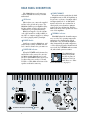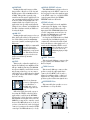
1
SRM450 ACTIVE
SOUND REINFORCEMENT
SPEAKER USER’S MANUAL
CAUTION
AVIS
RISK OF ELECTRIC SHOCK
DO NOT OPEN
RISQUE DE CHOC ELECTRIQUE
NE PAS OUVRIR
CAUTION: TO REDUCE THE RISK OF ELECTRIC SHOCK
DO NOT REMOVE COVER (OR BACK)
NO USER-SERVICEABLE PARTS INSIDE
REFER SERVICING TO QUALIFIED PERSONNEL
ATTENTION: POUR EVITER LES RISQUES DE CHOC
ELECTRIQUE, NE PAS ENLEVER LE COUVERCLE. AUCUN
ENTRETIEN DE PIECES INTERIEURES PAR L'USAGER. CONFIER
L'ENTRETIEN AU PERSONNEL QUALIFIE.
AVIS: POUR EVITER LES RISQUES D'INCENDIE OU
D'ELECTROCUTION, N'EXPOSEZ PAS CET ARTICLE
A LA PLUIE OU A L'HUMIDITE
The lightning flash with arrowhead symbol within an equilateral
triangle is intended to alert the user to the presence of uninsulated
"dangerous voltage" within the product's enclosure that may be
of sufficient magnitude to constitute a risk of electric shock to persons.
Le symbole éclair avec point de flèche à l'intérieur d'un triangle
équilatéral est utilisé pour alerter l'utilisateur de la présence à
l'intérieur du coffret de "voltage dangereux" non isolé d'ampleur
suffisante pour constituer un risque d'éléctrocution.
The exclamation point within an equilateral triangle is intended to
alert the user of the presence of important operating and maintenance
(servicing) instructions in the literature accompanying the appliance.
Le point d'exclamation à l'intérieur d'un triangle équilatéral est
employé pour alerter les utilisateurs de la présence d'instructions
importantes pour le fonctionnement et l'entretien (service) dans le
livret d'instruction accompagnant l'appareil.
SAFETY INSTRUCTIONS
1. Read Instructions — All the safety and operation instructions
should be read before this Mackie product is operated.
2. Retain Instructions — The safety and operating instructions
should be kept for future reference.
3. Heed Warnings — All warnings on this Mackie product and in
these operating instructions should be followed.
8. Heat — This Mackie product should be situated away from heat
sources such as radiators, or other devices which produce heat.
9. Power Sources — This Mackie product should be connected to a
power supply only of the type described in these operation
instructions or as marked on this Mackie product.
10. Power Cord Protection — Power supply cords should be routed
so that they are not likely to be walked upon or pinched by items
placed upon or against them, paying particular attention to cords at
plugs, convenience receptacles, and the point where they exit this
Mackie product.
11. Object and Liquid Entry — Care should be taken so that
objects do not fall into and liquids are not spilled into this Mackie
product.
12. Damage Requiring Service — This Mackie product should be
serviced only by qualified service personnel when:
A. The power-supply cord or the plug has been
damaged; or
B. Objects have fallen, or liquid has spilled into this
Mackie product; or
C. This Mackie product has been exposed to rain; or
D. This Mackie product does not appear to operate
normally or exhibits a marked change in performance;
or
E. This Mackie product has been dropped, or its chassis
damaged.
13. Servicing — The user should not attempt to service this
Mackie product beyond those means described in this operating
manual. All other servicing should be referred to the Mackie Service
Department.
4. Follow Instructions — All operating and other instructions
should be followed.
14. To prevent electric shock, do not use this polarized plug with an
extension cord, receptacle or other outlet unless the blades can be
fully inserted to prevent blade exposure.
5. Water and Moisture — This Mackie product should not be used
near water – for example, near a bathtub, washbowl, kitchen sink,
laundry tub, in a wet basement, near a swimming pool, swamp or
salivating St. Bernard dog, etc.
Pour prévenir les chocs électriques ne pas utiliser cette fiche
polariseé avec un prolongateur, un prise de courant ou une autre
sortie de courant, sauf si les lames peuvent être insérées à fond
sans laisser aucune pariie à découvert.
6. Cleaning — Clean only with a dry cloth.
15. Grounding or Polarization — Precautions should be taken so
that the grounding or polarization means of this Mackie product is
not defeated.
7. Ventilation — This Mackie product should be situated so
that its location or position does not interfere with its proper
ventilation. For example, the Component should not be situated
on a bed, sofa, rug, or similar surface that may block any
ventilation openings, or placed in a built-in installation such as a
bookcase or cabinet that may impede the flow of air through
ventilation openings.
PORTABLE CART WARNING
Carts and stands - The
Component should be used
only with a cart or stand
that is recommended by
the manufacturer.
A Component and cart
combination should be
moved with care. Quick
stops, excessive force, and
uneven surfaces may cause
the Component and cart
combination to overturn.
2
16. Power Precaution — Unplug this Mackie product during
lightning storms or when unused for long periods of time. Note that
this Mackie product is not completely disconnected from the AC
mains when the power switch is in the OFF position.
17. This apparatus does not exceed the Class A/Class B (whichever
is applicable) limits for radio noise emissions from digital apparatus
as set out in the radio interference regulations of the Canadian
Department of Communications.
ATTENTION —Le présent appareil numérique n’émet pas de bruits
radioélectriques dépassant las limites applicables aux appareils
numériques de class A/de class B (selon le cas) prescrites dans le
règlement sur le brouillage radioélectrique édicté par les ministere
des communications du Canada.
WARNING — To reduce the risk of fire or electric
shock, do not expose this appliance to rain or moisture.
Lend Me Your Ears
Exposure to extremely
high noise levels may
cause permanent hearing loss. Individuals vary
considerably in susceptibility to noise-induced hearing loss, but nearly everyone will
lose some hearing if exposed to sufficiently
intense noise for a period of time. The U.S.
Government’s Occupational Safety and
Health Administration (OSHA) has specified the permissible noise level exposures
shown in this chart.
Duration Per Day Sound Level dBA,
In Hours
Slow Response
8
90
6
92
4
95
3
97
2
100
1.5
102
1
105
0.5
110
0.25 or less
115
According to OSHA, any exposure in
excess of these permissible limits could
result in some hearing loss. To ensure
against potentially dangerous exposure to
high sound-pressure levels, it is recommended that all persons exposed to equipment
capable of producing these levels use hearing
protectors while this unit is in operation.
Ear plugs or protectors in the ear canals or
over the ears must be worn when operating
this amplification system in order to prevent
a permanent hearing loss if exposure is in
excess of the limits set forth here.
Typical
Example
Duo in small club
Subway Train
Very loud classical music
The SRM450
can produce a
maximum SPL
of 127 dB @ 1m.
Tami screaming at Adrian about deadlines
Loudest parts at a rock concert
CONTENTS
INTRODUCTION ....................................................... 4
HOOKUP DIAGRAMS ............................................... 6
Quick Start ........................................................ 6
REAR PANEL DESCRIPTION .................................... 8
IEC Socket .................................................. 8
POWER Switch ............................................ 8
POWER ON Indicator ................................... 8
TIMED TURNOFF ......................................... 8
THERMAL Indicator ..................................... 8
CONTOUR .................................................. 9
LOW CUT .................................................... 9
LEVEL ......................................................... 9
SIGNAL PRESENT Indicator ........................ 9
PEAK Indicator ............................................ 9
INPUT Connector ........................................ 9
THRU Connector ......................................... 9
ACCESSORY Plate ...................................... 9
CONNECTIONS ......................................................
PLACEMENT ..........................................................
RIGGING ................................................................
THERMAL CONSIDERATIONS ................................
AC POWER CONSIDERATIONS ..............................
SERVICE INFORMATION ........................................
Warranty Service .............................................
Troubleshooting ...............................................
Repair .............................................................
CARE AND MAINTENANCE ....................................
SRM450 SPECIFICATIONS .....................................
SRM450 BLOCK DIAGRAM ....................................
SRM450 LIMITED WARRANTY ...............................
Don’t forget to visit our website at www.mackie.com
for more information about this and other Mackie products.
Part No. 820-158-90 Rev. A 10/03
©2003 LOUD Technologies Inc. All Rights Reserved.
3
10
10
11
12
12
14
14
14
16
16
17
18
19
INTRODUCTION
Thank you for choosing LOUD Technologies’
Mackie active sound reinforcement speakers.
The SRM450 is an active two-way loudspeaker capable of extremely high sound
pressure levels, and designed to give you the
best performance of any loudspeaker in its
class and price range.
Our design goal was to build a sound reinforcement speaker with:
1. High precision, high output, and accurate playback.
2. Very wide, smooth dispersion of mid
and high frequencies.
3. Ergonomically correct physical design
for easy transport and set up.
Through the combined resources of our
top-notch mechanical and analog engineers,
and our experienced transducer engineers
at RCF, our transducer manufacturing facility in Italy, we were able to achieve our
design goals in every aspect. The result is a
sound reinforcement system equally at home
in a concert setting, in the studio, impromptu
concerts on the studio roof, in the cinema, or
in a home theater.
The Transducers
The SRM450 active speakers feature a
12-inch high-power low-frequency woofer
and a 1.75-inch titanium diaphragm highoutput precision compression driver. This
high-frequency driver is mounted on an
acoustically non-resonant exponential
waveguide, providing a wide, controlled
dispersion and precise reproduction of the
critical upper mid-range and high frequencies. The result is an unbelievably smooth
off-axis response that allows everyone in
the audience to experience the same highresolution audio no matter where they are
seated.
Each driver has been specifically designed
by our engineers for optimum performance
in the lightweight high-strength cabinet.
4
FR Series Power Amplifiers
To power these beautiful things, each
SRM450 includes two of our acclaimed FR
Series “Fast Recovery” power amplifiers. Our
exclusive design uses low negative feedback,
yet allows the amplifiers to maintain low distortion and stability and to quickly recover
when driven into clipping.
The amplifiers include the following
features:
• The low-frequency amplifier produces
up to 540 watts peak (300 continuous)
before clipping.
• The high-frequency amplifier produces
up to 150 watts peak (100 continuous)
before clipping.
• Each amplifier has its own compressor
circuit that acts when the input signal is
large enough to cause clipping, distortion and excessive voice coil heat. The
compressor will automatically decrease
the input signal to a safe level. The
compressor in the low-frequency amp
works independently from that in the
high-frequency amp.
• The low-frequency amp uses a servo
feedback loop which senses the current
flowing in the woofer coil. This controls
the low-frequency response and maintains low distortion at high output levels.
• The low-frequency amplifier also has a
sweeping filter. This will automatically
move the low cut-off frequency up or
down depending on the amplifier
output. For example, if the amplifier is
below clipping, the low-frequency cutoff point is 55 Hz. As it approaches
clipping, this shifts up smoothly to
120 Hz, providing more power reserves
and less distortion before clipping. This
happens quickly and continuously,
protecting the amplifer and the woofer
and reducing any noticable distortion.
Warning: Although the
amplifiers have these
protection circuits, you
must still make sure the
PEAK light is not blinking continuously. If it is, turn down your
mixer faders, or preamplifier gain, or turn
down the SRM450 LEVEL control.
The Crossover
The Active Advantage
The built-in electronic crossover is a
24 dB/octave Linkwitz-Riley design.
Although more expensive than other crossover designs, the benefits provided by the
Linkwitz-Riley design have been well documented. These benefits include:
• Absolutely flat frequency response
throughout the bandpass, without the
characteristic ripple near the crossover
point exhibited by other designs.
• The sharp 24 dB per octave roll-off of
the filters ensures that the transducers
aren’t reproducing frequencies outside
of their capabilities.
• The acoustic sum of the two driver
responses is unity at the crossover
frequency, resulting in perfect power
response.
• Our heroic engineers have worked
carefully to ensure that the SRM450
also provides perfect phase response.
This diligence has yielded phenomenal
accuracy, even if you are standing 20
feet away.
There are a number of advantages to using an active speaker system over a passive
loudspeaker:
• The internal crossover is active, and its
low power circuitry operates on linelevel signals. It does not waste speakerlevel power like a passive crossover with
large coils, caps, and resistors.
• The input signals are crossed over
before they reach the amplifiers, so each
amplifier only receives the correct
frequency range for its driver.
• The amplifiers are designed specifically
for these speaker load impedances.
There is no guesswork as to what load
each amplifier has to drive, so they can
provide maximum acoustic output from
the speakers, yet minimize the danger of
speaker damage due to overdriving a
lesser amplifier.
• The connecting wires between the
amplifier outputs and the drivers are
kept to a minimum, so the damping
factor of the amplifier isn’t compromised by the resistance of long speaker
cables. In addition, all the power from
the amplifier is transferred directly to
the drivers with no speaker cable losses.
• The acoustic sum of the outputs from
the two drivers is optimized electronically, as well as physically, so the
amplitude response is flat and there is
no lobing error.
• The presence of active circuits within
the speaker cabinet allow the designer
to add on extra details, such as a high
quality mic/line input section and
optional accessory modules.
In short, all the complex interconnected
components in the system are designed to
work in harmony with each other to produce the best possible sound. (Even for
Uncle Bert’s star performance on spoons!)
The Cabinet
The SRM450 cabinet was designed to be
the strongest molded composite cabinet on
the planet. This material is as strong as concrete, and rigid enough to prevent
unwanted vibrations in the cabinet. It has
built-in fly points for hanging, and a socket
in the bottom for mounting on a tripod
stand. Although it is an exceptional choice
for installed sound situations, its light
weight and durable finish also make it ideal
for portable sound system use. The asymmetrical trapezoidal design of the cabinet
makes it easy to use as a floor wedge for
stage monitor applications.
5
HOOKUP DIAGRAMS
Quick Start
1. Start with the following settings on the
back of the SRM450:
Turn the POWER switch off (down).
Set the TIMED TURNOFF, CONTOUR,
and LOW CUT switches out.
WARNING: Turn the
LEVEL control down
(counterclockwise)
before every use. If not,
you could be in for a
startling surprise, especially if the last
time you used it was with a microphone
and now you want to connect a linelevel source.
2. Connect the output from your signal
source (mixing console, microphone,
preamp, or other mic- or line-level
source) directly to the INPUT connector
on the back of the SRM450. It accepts
balanced line-level signals from mixers,
preamplifiers, CD players, tape decks,
etc., and accepts direct connections from
dynamic microphones.
DESIGNED BY MACKOIDS IN WOODINVILLE, WA • USA
DESIGNED BY MACKOIDS IN WOODINVILLE, WA • USA
DESIGNED BY MACKOIDS IN WOODINVILLE, WA • USA
DESIGNED BY MACKOIDS IN WOODINVILLE, WA • USA
3. Connect the supplied AC power cord to
the IEC socket on the back of the
SRM450. Plug the other end into an AC
outlet properly configured with the
correct voltage for your particular model.
4. Turn on your signal source. Make sure its
Master Volume control (if it has one) is
turned all the way down.
5. Turn on the SRM450 POWER switch.
6. Start the signal source, whether it be
speaking into a microphone or starting a
CD player. Adjust any volume controls on
the signal source for normal operation.
7. Slowly turn up the LEVEL control on
the back of the SRM450 until the
desired volume is reached (and the
PEAK light does not come on). Always
wear hearing protectors if you are close
when it is playing at high levels.
8. If there is no sound, always turn down
the SRM450 LEVEL control before
investigating. There may be a mixer or
preamplifier mute or tape switch
engaged, or a mic switch off.
DESIGNED BY MACKOIDS IN WOODINVILLE, WA • USA
Left
Line level
Output
DESIGNED BY MACKOIDS IN WOODINVILLE, WA • USA
Next
Next
DESIGNED BY MACKOIDS IN WOODINVILLE, WA • USA
DESIGNED BY MACKOIDS IN WOODINVILLE, WA • USA
Thru
Thru
1202-VLZ PRO
Right
Line level
Output
1202-VLZ PRO
Mixer or
Preamplifier
Daisy-chaining
SRM450s
SRM450: STEREO OPERATION WITH A MIXER, AND USING THE THRU JACK
6
For microphone connections, you can
daisy-chain up to two SRM450s using the
THRU jacks as shown.
Take great care to point any microphones away from the SRM450s, otherwise
you may get feedback.
Dynamic
Microphone
DESIGNED BY MACKOIDS IN WOODINVILLE, WA • USA
DESIGNED BY MACKOIDS IN WOODINVILLE, WA • USA
THRU
Output
SRM450: USING A MICROPHONE AND THE THRU JACK
The SRM450 can be
used with a Mackie
SWA1501 (or SWA1801)
subwoofer to create an incredibly powerful system.
The active crossover
inside the SWA1501
splits the full-range input
signal into two ranges.
The SWA1501 plays the
low-frequency range
through its 500 watt amplifier and 15-inch woofer,
and sends the high-pass
range to the SRM450.
The SRM450 can be
pole mounted on top of
the SWA1501 as shown,
saving the cost of a tripod
stand.
Pole
Mount
Line-level
Hi-pass
out
Pole
Mount
Power
Cord
Line-level
Hi-pass
out
ACTIVE
Full
Range
Power
Cord
ACTIVE
Full
Range
1202-VLZ PRO
Power
Cords
SWA1501
plays the low
frequencies
Power
Cords
SWA1501
plays the low
frequencies
SRM450: BIAMPING WITH A POWERED SUBWOOFER
7
REAR PANEL DESCRIPTION
The SRM450 has several connectors,
controls, and indicators that you should
understand.
IEC Socket
This is where you connect the supplied
AC linecord to provide AC power to the
SRM450’s built-in power amplifiers. Plug
the linecord into an AC socket properly
configured for your particular model.
Note: If you happen to lose the AC linecord, replacements are readily available at
any office or computer supply store. Always
use a three-pin plug with a ground pin.
POWER Switch
Switch up to turn the SRM450 on, and
switch down to turn it off. Make sure the
level control is down before you turn it on.
POWER ON Indicator
When the POWER switch is turned on,
and the linecord is connected to an active
AC Mains supply, this indicator, located
just above the POWER switch, glows to let
you know that you’re ready to rock and
roll. The cool blue LED on the front of the
speaker works in the same way.
DESIGNED BY MACKOIDS IN WOODINVILLE, WA • USA
8
TIMED TURNOFF
When this switch is pushed in, the builtin amplifiers turn on and off depending on
the presence or absence of an input signal.
An input signal level of –45 dBu (minimum) activates the auto-on function. A
silent period greater than three minutes
activates the auto-off function. The blue
LED on the front of the speaker reflects the
state of the amplifiers.
THERMAL Indicator
This LED lights if the heatsink temperature exceeds a safe operating temperature
and triggers the thermal safety switch.
When this occurs, the built-in amplifiers
shut down until the heatsink temperature
cools back down. Then the thermal switch
resets itself, the THERMAL indicator turns
off, and normal operation resumes.
If the SRM450 keeps
shutting down, make
sure there is plenty of
ventilation to the rear
panel. Please see “Thermal Considerations” on page 12.
CONTOUR
Pushing in this switch engages a filter
that provides 3 dB of boost to the low and
high frequencies (below 100 Hz and above
12 kHz). This provides a punchy, crisp
sound for most live music applications. You
can experiment with this switch by leaving
it out for a while, then pushing it in to determine which way sounds best for your
application. It is especially useful when listening at lower volumes, as it highlights the
bass like a Loudness switch, in addition to
boosting the highs.
LOW CUT
Pushing in this switch engages a low-cut
filter, which rolls off the low frequencies below 75 Hz. This is useful for minimizing
stage noise (rumble) and microphone handling noise.
It is highly recommended
that you engage this
switch when using the
SRM450 as a stage monitor. This allows the bass
amplifier to utilize its power for those frequencies useful in stage monitor
applications.
LEVEL
This is used to adjust the signal level, going into the built-in power amplifiers, from
Off up to 40 dB of gain. Since the SRM450
incorporates Mackie’s world-class low-noise
mic preamp technology, you can connect
either a line-level or a microphone-level signal
to the input, and use this control to adjust
the level correctly.
There is no phantom
power for a microphone,
so you should use a
dynamic mic, or use a
condensor type if it has
its own battery power.
Follow the Quick Start guide on page 6
for setting the LEVEL control. For most
applications, it will be in the NORMAL
position (12 o’clock). If you have a particularly high line-level signal connected to the
SRM450, you may need to turn the control
down to the LINE indication (9 o’clock). If
you have a low line-level or mic-level signal
connected, you may need to turn the LEVEL
control up to the MIC indication (3 o’clock).
SIGNAL PRESENT Indicator
This LED illuminates whenever there is
a signal present at the INPUT connector on
the rear panel. It senses the signal just prior
to the LEVEL control, so even if the LEVEL
control is turned down, the SIGNAL
PRESENT indicator still works.
PEAK Indicator
When the signal levels at the amplifier
outputs approach clipping, a soft compression circuit is activated that reduces the
input signal. The PEAK LED lights whenever the compression circuit is active. At
this time, the SRM450 may reach sound
pressure levels of 120 dB or more.
It’s okay for the PEAK indicator to blink
occasionally, but if it blinks frequently or
continuously, either turn down the signal
level at the mixer or other signal source, or
turn down the SRM450’s LEVEL control.
Wear hearing protection
if you are close to the
SRM450 playing at high
levels.
INPUT Connector
This is a female XLR-type connector that
accepts a balanced or unbalanced mic- or
line-level signal.
THRU Connector
This is a male XLR-type connector that
produces exactly the same signal that is
connected to the INPUT jack. It can be a
balanced or unbalanced mic- or line-level
signal. Use it to daisy-chain several active
speakers together off the same signal source.
ACCESSORY Plate
This removable plate provides access to
install future accessory modules.
9
CONNECTIONS
PLACEMENT
The SRM450 has a female XLR input
that accepts a balanced or unbalanced micor line-level signal. When connecting a balanced signal, be sure it’s wired per AES
(Audio Engineering Society) standards:
The SRM450 active speakers are designed to sit on the floor, a tabletop, or to fit
on a standard tripod speaker stand. They
can also be suspended by the rigging points,
shown opposite.
You can lay the cabinet down on its side
and use the SRM450 as a floor monitor. The
asymmetrical trapezoidal shape of the cabinet
provides a perfect angle for aiming up toward
performers from the front of the stage. When
used for monitor applications, we recommend engaging the LOW CUT filter.
Hot (+)
Cold (–)
Shield (Ground)
XLR
Pin 2
Pin 3
Pin 1
There is also a male XLR connector labeled THRU. This allows you to connect
more than one SRM450 to the output of
your mixing console. Simply plug the signal
source output into the first INPUT jack,
and patch that speaker’s THRU jack to the
next INPUT jack, and so on, daisy-chaining
multiple speakers (see diagram on page 6).
There is a limit to how
many you can daisy-chain
together. A general rule is
to maintain a load impedance ten times or more
than the source impedance to prevent excessive loading on the source. For example,
if your mixer has an output impedance of
120 ohms, then you can daisy chain up to
sixteen SRM450s. This is a load of 1250 ohms
(SRM450 input impedance=20 kohms;
16 of these in parallel=1250 ohms).
Since microphones typically have a
higher output impedance, you should limit
daisy-chaining from a mic source to two
SRM450s (see the diagram on page 7).
The THRU jack is wired straight from
the INPUT connector — there is no electronic circuitry between — so the signal
coming out of the THRU jack is exactly the
same as the signal going in.
As with any powered
components, protect
them from moisture. If
you are setting them up
outdoors, make sure they
are under cover if you expect rain.
The SRM450 generates
magnetic fields. Do not
place them closer than two
or three feet (60–100 cm)
from TV or computer
monitors. Check the screen for any change
in color or distortion. Do not place any
magnetic audio or video tapes or computer
discs near the SRM450s.
Room Acoustics
The SRM450 active speakers are designed to sound as neutral as possible; that
is, to reproduce the input signal as accurately as possible, monitoring the sound
rather than changing it.
Room acoustics play a crucial role in the
overall performance of a sound system.
However, the wide high-frequency dispersion of the SRM450 helps to minimize the
problems that typically arise.
Balanced XLR Connectors
Top
900
900 Dispersion
up to 20 kHz
10