1
AD450NX Server
System Product Guide
Order Number: 678269-002
Information in this document is provided in connection with Intel products. No license, express or implied, by estoppel or
otherwise, to any intellectual property rights is granted by this document. Except as provided in Intel's Terms and
Conditions of Sale for such products, Intel assumes no liability whatsoever, and Intel disclaims any express or implied
warranty, relating to sale and/or use of Intel products including liability or warranties relating to fitness for a particular
purpose, merchantability, or infringement of any patent, copyright or other intellectual property right. Intel products are not
designed, intended or authorized for use in any medical, life saving, or life sustaining applications or for any other
application in which the failure of the Intel product could create a situation where personal injury or death may occur. Intel
may make changes to specifications and product descriptions at any time, without notice. No part of this document may be
copied or reproduced in any form or by any means without prior consent of Intel.
The AD450NX Server System may contain design defects or errors known as errata which may cause the product to
deviate from published specifications. Current characterized errata are available on request. Copies of documents which
have an ordering number and are referenced in this document, or other Intel literature, may be obtained from:
Intel Corporation
P.O. Box 5937
Denver, CO 80217-9808
or call in North America 1-800-548-4725, Europe 44-0-1793-431-155, France 44-0-1793-421-777,
Germany 44-0-1793-421-333, other Countries 708-296-9333.
†
Third party brands and names are property of their respective owners.
Copyright 1998, Intel Corporation. All Rights Reserved.
2
Quick Reference and Conventions
For translated warnings, see Appendix C, “Warnings.”
Part I: User's Guide
1 Introduction to the High-performance Server
2 On-site Installation: Installing the Server
3 Power-on Self Test: Description/Running
4 Setup Utility: When to Run
5 System Setup Utility: When to Run
6 SCSISelect Utility: When to Run
7 Emergency Management Port Console: How to Use
8 FRU and SDR Load Utility: When to Run
9 Hot-swappable SCSI Hard Disk Drives: Installing/Hot Swapping
10 Hot-swappable Power Supplies: Hot Swapping
Part II: Service Technician's Guide
Safety Guidelines
11 Server Covers: Removing/Reinstalling
12 Server Components: Removing/Reinstalling
13 Boot Drives and Removable Media Drives:
Installing/Removing/Replacing
14 Power Distribution Backplane: Description/Voltages
15 SCSI Hot-docking Backplane: Description/SCSI IDs
16 I/O Baseboard: Description/Setting Configuration Jumpers
17 CPU Baseboard: Description/Setting Configuration Jumpers
3
AD450NX Server System Product Guide
18 Memory and Memory Terminator Modules: Description/Adding Memory
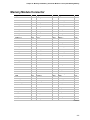
19 Interconnect Backplane: Description/Connectors
20 Power System: Description/Calculating Power Usage
21 Back-up Battery: Replacing/Disposing
22 Solving Problems: Troubleshooting/Error Messages
A Regulatory Specifications
B Equipment Log
C Warnings
Conventions
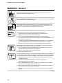
WARNING
WARNING indicates a hazard that can cause personal injury or
equipment damage if the hazard is not avoided.
CAUTION
CAUTION indicates a hazard that might cause personal injury, damage to
hardware, or software if the hazard is not avoided.
✏
NOTE
Notes provide information and may be used to emphasize a recommended
sequence of steps.
<F1>
A letter, number, symbol, or word enclosed in < > represents a key on your keyboard.
For example, the instruction "press <F1>" means press the key labeled "F1" on your
keyboard.
<Enter>
The <Enter> key is used to enter commands and responses to prompts. Some manuals
refer to <Enter> as RETURN, CARRIAGE RETURN, <CR>, or use an arrow. All of
these terms are interchangeable.
<x + y>
Two or three key names, separated by plus signs, indicate multiple-key entries. For
example, <Ctrl + Alt + Del> means hold down <Ctrl> and <Alt> and press <Del>.
_L
In all tables in this guide, active-low signal names have an “_L” symbol following the
name; for example, DSTBN3_L. Active-high signal names do not have a “_L” suffix.
4
Contents
Quick Reference and Conventions
For translated warnings, see Appendix C, “Warnings.” ......................................................... 3
Part I: User's Guide ............................................................................................................. 3
Part II: Service Technician's Guide...................................................................................... 3
Conventions ......................................................................................................................... 4
Part I: User's Guide
1 Introduction to the High-performance Server
Server Features ..................................................................................................................20
Chassis ...............................................................................................................................23
Controls and Indicators .......................................................................................................24
Server Security....................................................................................................................26
Front Bezel Key Lock Features...................................................................................27
Back of Chassis Padlock ............................................................................................28
Alarm Switches...........................................................................................................29
Password Protection...................................................................................................30
Secure Boot Mode......................................................................................................30
Boot Sequence Control...............................................................................................30
Boot Without Keyboard...............................................................................................30
Locked Power and Reset Switches.............................................................................30
Diskette Write Protect .................................................................................................30
Video Blanking............................................................................................................31
2 On-site Installation: Installing the Server
Selecting a Site ...................................................................................................................33
Physical Specifications ........................................................................................................34
Environmental Specifications ..............................................................................................34
After Unpacking the Server .................................................................................................34
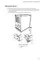
Moving the Server ...............................................................................................................35
Connecting Peripheral Devices ...........................................................................................36
Obtaining Power Cords .......................................................................................................38
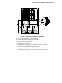
Turning on Your Server .......................................................................................................38
Power-on Self Test .....................................................................................................41
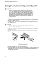
Booting From the Server Configuration Software CD ..........................................................42
Copying Configuration Software to Diskettes ......................................................................43
Installing Video Drivers........................................................................................................43
Installing SCSI Drivers ........................................................................................................43
Server Won’t Boot From the CD..........................................................................................44
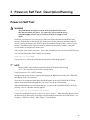
3 Power-on Self Test: Description/Running
Power-on Self Test..............................................................................................................47
5
AD450NX Server System Product Guide
4 Setup Utility: When to Run
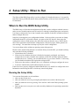
When to Run the BIOS Setup Utility ....................................................................................49
Running the Setup Utility ............................................................................................49
Main Menu..................................................................................................................51
Advanced Menu..........................................................................................................53
Security Menu.............................................................................................................57
Server Menu ...............................................................................................................58
Boot Menu ..................................................................................................................60
Exit Menu Selections ..................................................................................................61
5 System Setup Utility: When to Run
When to Run the System Setup Utility.................................................................................63
What You Need to Do .........................................................................................................64
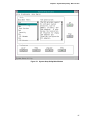
Running the SSU.................................................................................................................64
Starting the SSU.........................................................................................................65
Customizing the SSU..................................................................................................66
Launching a Task .......................................................................................................66
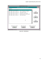
Resource Configuration Add-in (RCA) Window...........................................................68
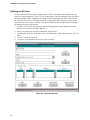
Defining an ISA Card....................................................................................70
Adding and Removing ISA Cards .................................................................71
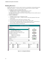
Modifying Resources....................................................................................72
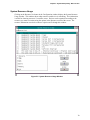
System Resource Usage..............................................................................73
Multiboot Add-in..........................................................................................................74
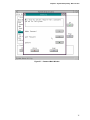
Security Add-in ...........................................................................................................76
To Set the User Password ...........................................................................76
To Change or Clear the User Password.......................................................76
To Set the Administrator Password ..............................................................76
To Change or Clear the Administrator Password .........................................76
Security Options...........................................................................................76
System Event Log Manager Add-in ............................................................................78
Exiting the SSU ..........................................................................................................79
6 SCSISelect Utility: When to Run
When to Run the SCSISelect Utility.....................................................................................81
Running the SCSISelect Utility ............................................................................................81
Main Menu for AIC-7880.............................................................................................82
Configuration Menu ......................................................................................82
Boot Device Configuration Menu..................................................................83
SCSI Device Configuration Menu .................................................................83
Advanced Configuration Options..................................................................84
SCSI Disk Utilities Menu ..............................................................................85
Exit Menu ...................................................................................................85
Main Menu for AHA-3940AUW ...................................................................................86
Configuration Menu ......................................................................................87
Boot Device Configuration Menu..................................................................87
SCSI Device Configuration Menu .................................................................88
6
Contents
Advanced Configuration Options..................................................................89
SCSI Disk Utilities Menu ..............................................................................90
Exit Menu ...................................................................................................90
7 Emergency Management Port Console: How to Use
How EMP Console Works ...................................................................................................92
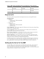
Requirements......................................................................................................................94
Setting Up the Server for the EMP ......................................................................................94
Server Menu ...............................................................................................................95
Console Redirection Submenu ...................................................................................95
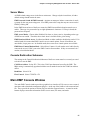
Main EMP Console Window ................................................................................................95
Toolbar .....................................................................................................................96
Status Bar...................................................................................................................96
EMP Console Main Menu ...........................................................................................96
Server Control Operations...................................................................................................97
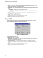
Connect .....................................................................................................................97
Power On/Off..............................................................................................................98
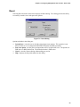
Reset
.....................................................................................................................99
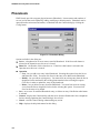
Phonebook ........................................................................................................................100
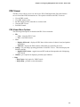
FRU Viewer ..............................................................................................................101
FRU Viewer Menu Options.........................................................................101
8 FRU and SDR Load Utility: When to Run
When to Run the FRUSDR Load Utility .............................................................................103
What You Need to Do .......................................................................................................103
How You Use the FRUSDR Load Utility ............................................................................104
Command Line Format .............................................................................................104
Parsing the Command Line ......................................................................................104
Displaying Usage Information ...................................................................................104
Displaying a Given Area ...........................................................................................106
Displaying DMI Area...................................................................................106
Displaying FRU Area..................................................................................106
Displaying SDR Area..................................................................................108
Using Specified CFG File..........................................................................................109
Displaying Utility Title and Version .............................................................109
Configuration File .......................................................................................109
Prompting for Product Level FRU Information ............................................109
Filtering Sensor Data Record From the SDR File .......................................109
Updating the SDR Nonvolatile Storage Area ..............................................109
Updating FRU Nonvolatile Storage Area ....................................................109
Updating DMI Nonvolatile Storage Area.....................................................110
Cleaning Up and Exiting .............................................................................110
9 Hot-swappable SCSI Hard Disk Drives: Installing/Hot Swapping
Hot-docking Bays ..............................................................................................................111
Tools and Supplies You Need ...........................................................................................111
Equipment Log .........................................................................................................111
7
AD450NX Server System Product Guide
SCSI SCA Hard Disk Drives..............................................................................................112
Mounting a SCSI SCA Hard Disk Drive in a Carrier ..................................................112
Installing a SCSI SCA Hard Disk Drive in a Hot-docking Bay ...................................114
Hot-swapping a SCSI SCA Hard Disk Drive .............................................................116
SCSI Drive Status LED Descriptions ..........................................................116
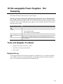
10 Hot-swappable Power Supplies: Hot Swapping
Tools and Supplies You Need ...........................................................................................119
Equipment Log .........................................................................................................119
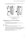
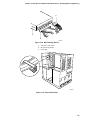
Hot Swapping a Power Supply ..........................................................................................120
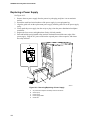
Removing a Power Supply........................................................................................120
Replacing a Power Supply........................................................................................122
Part II: Service Technician's Guide
Safety Guidelines
Warnings and Cautions .....................................................................................................125
11 Server Covers: Removing/Reinstalling
Warnings and Cautions .....................................................................................................127
Tools and Supplies You Need ...........................................................................................127
Equipment Log .........................................................................................................127
Covers...............................................................................................................................127
Removing the Top Cover..........................................................................................128
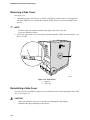
Removing a Side Cover............................................................................................130
Reinstalling a Side Cover..........................................................................................130
Reinstalling the Top Cover........................................................................................131
Removing the Plastic Front Bezel .............................................................................132
Reinstalling the Plastic Front Bezel...........................................................................132
Removing the Snap-on Drive Bay Cover ..................................................................134
Reinstalling the Snap-on Drive Bay Cover ................................................................134
12 Server Components: Removing/Reinstalling
Warnings and Cautions .....................................................................................................137
Tools and Supplies You Need ...........................................................................................137
Equipment Log .........................................................................................................137
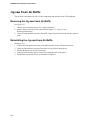
Jig-saw Foam Air Baffle ....................................................................................................138
Removing the Jig-saw Foam Air Baffle .....................................................................138
Reinstalling the Jig-saw Foam Air Baffle...................................................................138
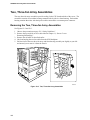
Two, Three-fan Array Assemblies .....................................................................................140
Removing the Two, Three-fan Array Assemblies......................................................140
Reinstalling the Two, Three-fan Array Assemblies....................................................141
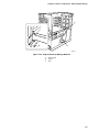
Support Panel for Terminator and Memory Modules .........................................................142
Removing the Support Panel ....................................................................................142
Reinstalling the Support Panel..................................................................................142
8
Contents
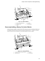
Terminator and Memory Modules......................................................................................144
Removing a Memory Module ....................................................................................144
Reinstalling a Memory Module..................................................................................144
Removing/Installing a Memory Terminator Module ...................................................145
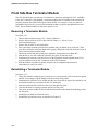
Front Side Bus Terminator Module....................................................................................146
Removing a Terminator Module................................................................................146
Reinstalling a Terminator Module .............................................................................146
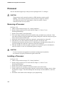
Processor ..........................................................................................................................148
Removing a Processor .............................................................................................148
Installing a Processor ...............................................................................................148
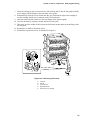
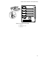
DC to DC Converter VRM .................................................................................................150
Removing a DC to DC Converter VRM.....................................................................150
Installing a DC to DC Converter VRM.......................................................................150
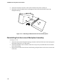
Interconnect Backplane Assembly.....................................................................................152
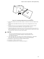
Removing the Interconnect Backplane Assembly .....................................................152
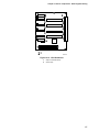
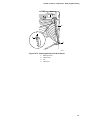
Reinstalling the Interconnect Backplane Assembly...................................................154
CPU Baseboard ................................................................................................................156
Removing the CPU Baseboard.................................................................................156
Reinstalling the CPU Baseboard...............................................................................156
Front Panel Board .............................................................................................................158
Removing the Front Panel Board..............................................................................158
Reinstalling the Front Panel Board ...........................................................................158
Retaining Bracket for Add-in Boards .................................................................................160
Removing the Retaining Bracket for Add-in Boards ..................................................160
Reinstalling the Retaining Bracket for Add-in Boards................................................160
Add-in Boards ...................................................................................................................162
Installing an Add-in Board.........................................................................................162
Removing an Add-in Board.......................................................................................165
Three-fan Array Assembly.................................................................................................166
Removing the Three-fan Array Assembly .................................................................166
Reinstalling the Three-fan Array Assembly ...............................................................166
I/O Riser Card ...................................................................................................................168
Removing the I/O Riser Card....................................................................................168
Reinstalling the I/O Riser Card .................................................................................168
I/O Baseboard ...................................................................................................................170
Removing the I/O Baseboard....................................................................................170
Reinstalling the I/O Baseboard .................................................................................170
SCSI Hot-docking Backplane ............................................................................................172
Removing the SCSI Backplane.................................................................................172
Reinstalling the SCSI Backplane ..............................................................................172
Power Distribution Backplane............................................................................................174
Removing the Power Distribution Backplane ............................................................174
Reinstalling the Power Distribution Backplane ..........................................................176
Intelligent Chassis Management Bus (ICMB) Board..........................................................176
Removing the ICMB Board .......................................................................................176
Reinstalling the ICMB Board.....................................................................................176
9
AD450NX Server System Product Guide
13 Boot Drives and Removable Media Drives:
Installing/Removing/Replacing
Warnings and Cautions .....................................................................................................179
Tools and Supplies You Need ...........................................................................................179
Equipment Log .........................................................................................................179
Boot Hard Disk Drive.........................................................................................................180
Installing the Boot Hard Disk Drive ...........................................................................180
Removing the Boot Hard Disk Drive .........................................................................180
Mass Storage Devices ......................................................................................................182
Installing a Mass Storage Device..............................................................................182
Removing a Mass Storage Device............................................................................186
Diskette Drive....................................................................................................................186
Removing the Diskette Drive ....................................................................................186
Replacing the Diskette Drive.....................................................................................186
IDE CD-ROM Drive ...........................................................................................................188
Removing the IDE CD-ROM Drive............................................................................188
Replacing the IDE CD-ROM Drive ............................................................................190
14 Power Distribution Backplane: Description/Voltages
Warnings and Cautions .....................................................................................................191
Power Distribution Backplane............................................................................................191
240 VA Protection.....................................................................................................191
Two-speed Fan Voltage............................................................................................192
I2C Bus ...................................................................................................................192
Power Supply Present and Fault Detection...............................................................192
Power Supply Revision Detection .............................................................................192
Interconnect Cable Detect ........................................................................................192
Fourth Power Supply Cable Good Detection ............................................................192
Power Good..............................................................................................................193
Power On .................................................................................................................193
5 V Quick Discharge .................................................................................................193
15 SCSI Hot-docking Backplane: Description/SCSI IDs
Warnings and Cautions .....................................................................................................195
SCSI Hot-docking Backplane ............................................................................................195
SCSI ID Configurations.............................................................................................196
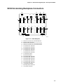
SCSI Hot-docking Backplane Connectors .........................................................................197
Wide/Fast SCSI Input16-Bit Connectors, J1 & J2 .....................................................198
Wide/Fast SCSI 16-Bit SCA Type Connectors, J10-J15 & J20-J25 ..........................200
Hot-swap Control Connector.....................................................................................201
+12 V Power Connector............................................................................................202
+5 V Power Connector .............................................................................................202
Fan Connector..........................................................................................................202
Intrusion Switch Connector .......................................................................................203
10
Contents
16 I/O Baseboard: Description/Setting Configuration Jumpers
Warnings and Cautions .....................................................................................................205
Input/Output (I/O) Baseboard Features .............................................................................205
32-bit PCI Expansion Slots .......................................................................................206
64-bit PCI Expansion Slots .......................................................................................206
ISA Expansion Slot ...................................................................................................206
PCI Video Controller .................................................................................................207
Video Modes ..............................................................................................207
SCSI Controllers.......................................................................................................210
Adaptec AIC-7880......................................................................................210
Adaptec AHA-3940AUW ............................................................................210
IDE Controller ...........................................................................................................210
Server Management (SM) ........................................................................................211
I/O Riser Card...........................................................................................................213
I/O Baseboard Configuration Jumpers ..............................................................................214
Restoring CMOS to Default Values...........................................................................216
Clearing the Password..............................................................................................216
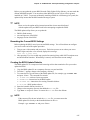
Updating the BIOS....................................................................................................216
Recording the Current BIOS Settings.........................................................217
Creating the BIOS Update Diskette............................................................217
Running the BIOS Update Utility ................................................................218
Recovering the BIOS..................................................................................218
Updating BMC, FPC, and HSC Firmware .................................................................219
Boot Sequence..................................................................................................................220
I/O Baseboard Layout .......................................................................................................221
I/O Baseboard Connectors ................................................................................................222
Expander Bus Connector: Signal Section ................................................................222
Expander Bus Connector: Power Section ................................................................225
Connectors J2J1B and J2J1C, 3.3 V..........................................................225
Connector J2J1D, 5 V and 12 V .................................................................225
Connectors J2J1E, J2J1F, J2J1G and J2J1H, 5 V.....................................225
Connector J2J1J, 3.3 V and 5 V.................................................................225
32-bit PCI Connector ................................................................................................226
64-bit PCI Connector ................................................................................................227
ISA Connector ..........................................................................................................228
Diskette Drive Port....................................................................................................229
Wide/Fast 16-bit SCSI Port.......................................................................................230
IDE Port ...................................................................................................................231
I2C Connector ...........................................................................................................232
Front Panel Connector..............................................................................................232
Legacy Connector ....................................................................................................233
USB Port ..................................................................................................................233
Keyboard and Mouse Ports ......................................................................................234
Serial Ports ...............................................................................................................234
Parallel Port ..............................................................................................................235
XICMB Connectors ...................................................................................................235
VGA Video Port ........................................................................................................236
11
AD450NX Server System Product Guide
17 CPU Baseboard: Description/Setting Configuration Jumpers
Warnings and Cautions .....................................................................................................237
CPU Baseboard Features .................................................................................................237
Processors ...............................................................................................................238
Memory Interface......................................................................................................238
DC-to-DC Voltage Converters ..................................................................................238
DS1624 SEEPROM ...................................................................................238
Interconnect Interface...............................................................................................239
Front Side Bus..........................................................................................................239
Front Side Bus Terminator Module ...........................................................................239
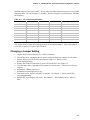
CPU Baseboard Configuration Jumpers............................................................................240
Changing a Jumper Setting ......................................................................................241
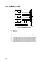
CPU Baseboard Layout.....................................................................................................242
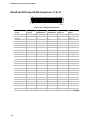
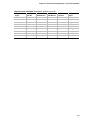
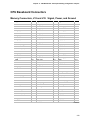
CPU Baseboard Connectors .............................................................................................243
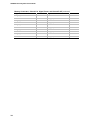
Memory Connectors, J18 and J19: Signal, Power, and Ground...............................243
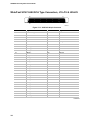
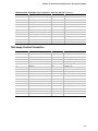
Expander Bus Connector: Signal Section ................................................................247
Expander Bus Connector: Power Section ................................................................249
3.3 V Connectors J21A, B, C, & D..............................................................249
5 V Connectors J21E & F...........................................................................250
12 V Connector J21G.................................................................................250
12 V Connectors J21H & J .........................................................................250
18 Memory and Memory Terminator Modules: Description/Adding Memory
Warnings and Cautions .....................................................................................................251
Module Features ...............................................................................................................251
EDO DRAM Array .............................................................................................................252
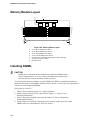
Memory Module Layout.....................................................................................................256
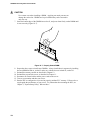
Installing DIMMs................................................................................................................256
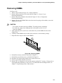
Removing DIMMs..............................................................................................................259
System Management Interface..........................................................................................260
Memory Module Connector ...............................................................................................261
19 Interconnect Backplane: Description/Connectors
Warnings and Cautions .....................................................................................................265
Interconnect Backplane.....................................................................................................265
Server Management Connector................................................................................267
Interconnect Backplane Power Connectors ..............................................................268
Interconnect to CPU Baseboard: Signal Section......................................................268
Interconnect to CPU Baseboard: Power Section .....................................................271
3.3 V Connectors J21, J22, J23, and J24...................................................271
5 V Connectors J25 and J26 ......................................................................271
12 V Connector J27 ...................................................................................272
12 V Connectors J28 and J29 ....................................................................272
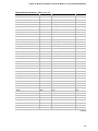
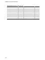
Interconnect to I/O Baseboard: Signal Section ........................................................272
12
Contents
Interconnect to I/O Baseboard: Power Section ........................................................275
3.3 V Connectors J38 and J39 ...................................................................275
5 V and 12 V Connector J40 ......................................................................275
5 V Connectors J41, J42, J43, and J44......................................................276
3.3 V and 5 V Connector J45 .....................................................................276
20 Power System: Description/Calculating Power Usage
Warnings and Cautions .....................................................................................................277
Power System ...................................................................................................................277
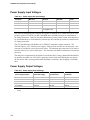
Power Supply Input Voltages....................................................................................278
Power Supply Output Voltages .................................................................................278
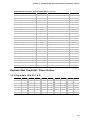
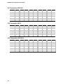
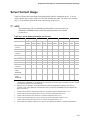
Server Current Usage .......................................................................................................279
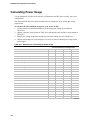
Calculating Power Usage ..................................................................................................280
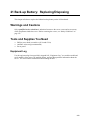
21 Back-up Battery: Replacing/Disposing
Warnings and Cautions .....................................................................................................283
Tools and Supplies You Need ...........................................................................................283
Equipment Log .........................................................................................................283
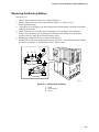
Back-up Battery.................................................................................................................284
Replacing the Back-up Battery .................................................................................285
22 Solving Problems: Troubleshooting/Error Messages
Warnings and Cautions .....................................................................................................287
Resetting the Server..........................................................................................................287
Initial Startup of the Server................................................................................................287
Checklist...................................................................................................................287
Running New Application Software ...................................................................................288
Checklist...................................................................................................................288
After the Server Has Been Running Correctly ...................................................................289
Checklist...................................................................................................................289
More Troubleshooting Procedures ....................................................................................290
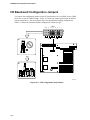
Preparing the Server for Diagnostic Testing .............................................................290
Monitoring POST ......................................................................................................290
Verifying Proper Operation of the Server Lights........................................................290
Confirming Loading of the Operating System ...........................................................291
Specific Problems and Corrective Actions .........................................................................291
Power Light Does Not Light ......................................................................................291
Server Cooling Fans Do Not Rotate Properly ...........................................................292
No Characters Appear on Screen.............................................................................293
Characters Are Distorted or Incorrect .......................................................................293
Incorrect or no Beep Codes......................................................................................293
Diskette Drive Activity Light Does Not Light ..............................................................294
Hard Disk Drive Activity Light Does Not Light ...........................................................294
Problems With Application Software .........................................................................295
Server Powers Up and Immediately Powers Down...................................................295
Error Codes and Messages...............................................................................................295
Port 80h Codes.........................................................................................................296
POST Error Codes and Messages ...........................................................................299
13
AD450NX Server System Product Guide
A Regulatory Specifications
Declaration of Compliance ................................................................................................303
Safety Compliance ............................................................................................................303
Electromagnetic Compatibility (EMC) ................................................................................303
Electromagnetic Compatibility Notice (USA) .............................................................304
FCC Compliance Statement.......................................................................304
Electromagnetic Compatibility Notices (International) ...............................................304
B Equipment Log
Equipment Log ..................................................................................................................305
C Warnings
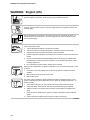
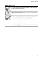
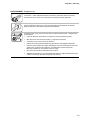
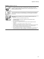
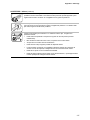
WARNING: English (US) ..................................................................................................310
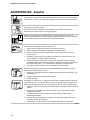
AVERTISSEMENT: Français............................................................................................312
WARNUNG: Deutsch .......................................................................................................314
AVVERTENZA: Italiano ....................................................................................................316
ADVERTENCIAS: Español...............................................................................................318
Index .....................................................................................................................................321
Figures
1-1.
1-2.
1-3.
1-4.
1-5.
1-6.
1-7.
2-1.
2-2.
2-3.
2-4.
2-5.
2-6.
2-7.
5-1.
5-2.
5-3.
5-4.
5-5.
5-6.
5-7
5-8.
7-1.
7-2.
7-3.
7-4.
14
High-performance Server .........................................................................................19
Server, Back/Left Side View .....................................................................................23
Server, Back/Right Side View ...................................................................................23
Server Controls and Indicators .................................................................................25
Front Bezel Security Key Lock..................................................................................27
Top and Side Covers Security Padlock.....................................................................28
Alarm Switches.........................................................................................................29
Server Casters .........................................................................................................35
Server I/O Panel.......................................................................................................37
Power Supplies With Safety Interlocks .....................................................................39
Server Power and Reset Switches ...........................................................................40
CD-ROM Drive .........................................................................................................42
Boot Menu ................................................................................................................44
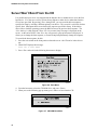
CD-ROM Boot Menu ................................................................................................44
System Setup Utility Main Window ...........................................................................67
RCA Window ............................................................................................................69
Define ISA Window...................................................................................................70
Configuration Window...............................................................................................72
System Resource Usage Window ............................................................................73
Multiboot Main Window.............................................................................................75
Password Main Window ...........................................................................................77
System Event Log Main Window ..............................................................................79
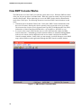
EMP Console in Command State .............................................................................92
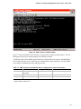
EMP Console in Redirect State ................................................................................93
Connect Dialog .........................................................................................................97
Power On/Off Dialog.................................................................................................98
Contents
7-5. Reset Dialog.............................................................................................................99
7-6. Phonebook Dialog ..................................................................................................100
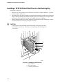
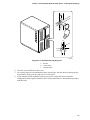
9-1. Hard Disk Drive and Carrier....................................................................................113
9-2. Hard Disk Drive and Carrier Assembly ...................................................................113
9-3. Installing a Hard Disk Drive ....................................................................................114
9-4. Front Bezel Security Key Lock................................................................................115
9-5. Hot-swapping a Hard Disk Drive.............................................................................117
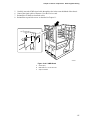
10-1. Removing a Power Supply .....................................................................................121
10-2. Removing/Replacing a Power Supply.....................................................................122
11-1. Top Cover...............................................................................................................129
11-2. Side Covers............................................................................................................130
11-3. Plastic Front Bezel..................................................................................................133
11-4. Snap-on Plastic Drive Bay Cover............................................................................135
12-1. Jig-saw Foam Air Baffle..........................................................................................139
12-2. Two, Three-fan Array Assemblies...........................................................................140
12-3. Two, Three-fan Array Assemblies...........................................................................141
12-4. Support Panel for Memory Modules .......................................................................143
12-5. Memory Module......................................................................................................145
12-6. Terminator Module .................................................................................................145
12-7. Front Side Bus Terminator Module .........................................................................147
12-8. Removing a Processor ...........................................................................................149
12-9. DC to DC Converter VRM.......................................................................................151
12-10. Interconnect Backplane Assembly..........................................................................153
12-11. Detaching the Mechanical Unit From the Backplane ..............................................154
12-12. Attaching the Mechanical Unit to the Backplane.....................................................155
12-13. CPU Baseboard .....................................................................................................157
12-14. Front Panel Board ..................................................................................................159
12-15. Retaining Bracket for Add-in Boards ......................................................................161
12-16. I/O Baseboard Expansion Slots..............................................................................163
12-17. Expansion Slot Cover.............................................................................................163
12-18. Installing an Add-in Board ......................................................................................164
12-19. Three-fan Array Assembly......................................................................................167
12-20. I/O Riser Card ........................................................................................................169
12-21. I/O Baseboard ........................................................................................................171
12-22. SCSI Backplane .....................................................................................................173
12-23. Power Distribution Backplane.................................................................................175
12-24. ICMB Board............................................................................................................177
13-1. Boot Hard Disk Drive ..............................................................................................181
13-2. Drive Bay Filler Panels ...........................................................................................183
13-3. Drive Bay EMI Shield..............................................................................................183
13-4. Snap-in Plastic Slide Rails ......................................................................................184
13-5. Mass Storage Device .............................................................................................185
13-6. Strain Relief Clips ...................................................................................................185
13-7. Diskette Drive .........................................................................................................187
13-8. IDE CD-ROM Drive ................................................................................................189
13-9. Snap-in Plastic Slide Rails ......................................................................................190
15-1. SCSI Backplane .....................................................................................................197
15-2. SCSI 68-pin Connector...........................................................................................198
15
AD450NX Server System Product Guide
15-3.
16-1.
16-2.
16-3.
17-1.
17-2.
18-1.
18-2.
18-3.
18-4.
18-5.
18-6.
18-7.
18-8.
19-1.
21-1.
SCSI SCA 80-pin Connector ..................................................................................200
I/O Riser Card ........................................................................................................213
J3H1 Configuration Jumper Block ..........................................................................214
I/O Baseboard Layout.............................................................................................221
J31 Jumper Block ...................................................................................................240
CPU Baseboard Layout ..........................................................................................242
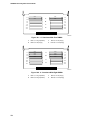
4:1 Interleave With Four DIMMs .............................................................................254
4:1 Interleave With Eight DIMMs ............................................................................254
4:1 Interleave With 12 DIMMs ................................................................................255
4:1 Interleave With 16 DIMMs ................................................................................255
Memory Module Layout ..........................................................................................256
DIMM Orientation ...................................................................................................257
Properly Seated DIMM ...........................................................................................258
Removing DIMMs ...................................................................................................259
Interconnect Backplane ..........................................................................................266
Lithium Back-up Battery .........................................................................................285
Tables
7-1.
7-2.
16-1.
17-1.
17-2.
18-1.
20-1.
20-2.
20-3.
20-4.
20-5.
16
EMP Console Access Modes (Server configured for console redirection) .................93
EMP Console Access Modes (Server not configured for console redirection) ...........94
Configuration Jumpers ............................................................................................215
J31 Jumpers for VRMs and Server Management ....................................................240
J31 Jumpers for Bus Ratios.....................................................................................241
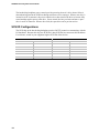
Memory Module DIMM Support...............................................................................252
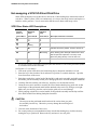
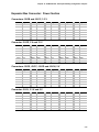
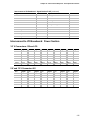
Power Supply AC Input Ratings...............................................................................278
Power Supply Output Ratings..................................................................................278
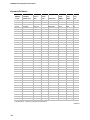
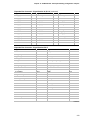
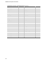
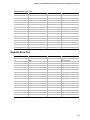
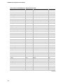
Server Board Set Voltages and Currents.................................................................279
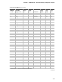
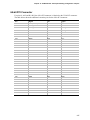
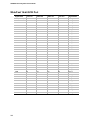
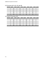
Worksheet for Calculating DC Power Usage ...........................................................280
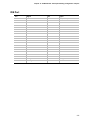
Total Combined Power Used by Your Server ..........................................................281
Part I: User's Guide
1 Introduction to the High-performance Server
2 On-site Installation: Installing the Server
3 Power-on Self Test: Description/Running
4 Setup Utility: When to Run
5 System Setup Utility: When to Run
6 SCSISelect Utility: When to Run
7 Emergency Management Port Console: How to Use
8 FRU and SDR Load Utility: When to Run
9 Hot-swappable SCSI Hard Disk Drives: Installing/Hot Swapping
10 Hot-swappable Power Supplies: Hot Swapping
17
White text
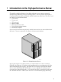
1 Introduction to the High-performance Server
The modular scaleable architecture of your high-performance server supports symmetrical
multiprocessing (SMP) and a variety of operating systems. The server comes with Peripheral
Component Interconnect (PCI) and Industry Standard Architecture (ISA) buses. The server board
set consists of seven individual boards.
• I/O baseboard
• I/O riser card
• CPU baseboard
• Memory module
• Memory terminator module
• Front side bus terminator module
• Interconnect backplane
The I/O and CPU baseboards are physically installed back to back on the center bulkhead inside
the chassis. They are connected to each other by the interconnect backplane.
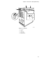
OM06192
Figure 1-1. High-performance Server
The easy-to-integrate server chassis contains a 3.5-inch diskette drive in the 3.5-inch bay, a
CD-ROM drive in the top 5.25-inch bay, and, depending on the server configuration, up to four
420 watt autoranging power supplies. The other three 5.25-inch bays can house mass storage
devices such as tape, DVD, and CD-ROM drives. Any two adjacent 5.25-inch bays can be
converted into a single full-height bay. A 3.5-inch bay above the 5.25-inch bays provides space
for a boot hard disk drive—IDE or SCSI. The twelve 3.5-inch hot-docking bays, when fully
19
AD450NX Server System Product Guide
configured with 9 GB hard disk drives, provide the server with up to 108 GB of storage. However,
the total amount of data storage can change with higher capacity hard disk drives. The
hot-docking bays allow hot-swapping of Small Computer System Interface (SCSI) hard disk drives
without shutting down the server.
The server can easily accommodate the needs of a variety of high performance applications—for
example, network servers, multiuser systems, and large database operations. As your application
requirements increase, you can upgrade your server with
• More powerful processors
• Additional memory
• Other peripheral devices
• Add-in I/O boards
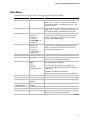
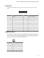
Server Features
Feature
Comment
Power system with redundancy
The 420 watt autoranging power supplies include integrated fans for
cooling. The server requires a minimum of three power supplies. In a
server with four power supplies, the fourth one is redundant. The
supplies can be replaced—hot-swapped—in a redundant configuration
without turning the server power off. Each supply comes with a springloaded mechanical interlock. It prevents removal of the supply when
the AC power cord is attached.
Server chassis
The electrogalvanized metal used in manufacturing the server chassis
minimizes electromagnetic interference (EMI) and radio frequency
interference (RFI).
Four power supply bays.
3.5-inch diskette drive in the 3.5-inch bay.
Four 5.25-inch half-height bays for removable media devices—top bay
contains a CD-ROM drive.
A 3.5-inch bay above the 5.25-inch bays provides space for a 1-inch
high by 3.5-inch wide SCSI or IDE boot hard disk drive (accessible
from inside the server)
Twelve 3.5-inch hot-docking bays arranged in two rows; each row has
space for either six 1-inch high or six 1.6-inch high, 3.5-inch wide single
connector attachment (SCA) SCSI hard disk drives; each row is on a
separate SCSI channel.
Eleven I/O expansion slot covers.
The plastic front bezel provides airflow and easy access to drives in the
hot-docking bays. The removable top and side covers provide proper
airflow and easy access to components inside the server. You must
remove the top cover before you can remove the side covers. A
padlock (not supplied) on the back of the chassis secures the covers to
prevent unauthorized entry into the server—only technically qualified
personnel should remove the server covers.
continued
20
Chapter 1 Introduction to the High-performance Server
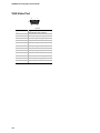
Server Features (continued)
Feature
Comment
Cooling fans
An array of three fans cools and circulates air through the I/O
baseboard side of the server.
Two arrays of three fans cool and circulate air through the CPU
baseboard side of the server.
Integrated power supply fans (three or four) cool and circulate air
through the power supplies and the hot-docking bays.
Front panel board
The front panel board provides the user interface to the server. The
board allows other servers to communicate with this server, even while
power is down, via an Intelligent Chassis Management Bus (ICMB).
Push-button switches control power-up, reset, and nonmaskable
interrupt (NMI) functions.
LEDs indicate power on, power supply failure, hard drive failure, or a
fan or other server cooling failure.
An LCD panel provides information about boot status, available number
of processors, and other server management information.
Server management
Inter-integrated circuit bus (I2C) for diagnostic and intrachassis
communication. ICMB for interchassis platform management
communications.
Real-time clock/calendar (RTC).
Front panel controls and indicators (LEDs).
Basic Input/Output System (BIOS), Power-on Self Test (POST), and
Setup Utility stored in a flash memory device.
SCSISelect † Utility.
System Setup Utility (SSU).
Emergency Management Port (EMP) Utility.
Field Replacement Unit (FRU) and Sensor Data Repository (SDR)
Load Utility.
CPU baseboard
The baseboard supports up to four processors, each processor is
packaged in a Single Edge Contact (S.E.C.) cartridge; the baseboard
supports two memory modules.
Processor packaged in an S.E.C.
cartridge
The cartridge includes the processor core and L2 cache components.
Front side bus (FSB) terminator
module
The module plugs into any unpopulated slot 2 connector on the CPU
baseboard. The module terminates the FSB GTL+ signals of the slot 2
connectors when a processor is not installed in them.
Memory module
Each memory module supports up to 4 GB of ECC memory using
sixteen 72-bit dual inline memory modules (DIMMs). (The CPU
baseboard requires two memory modules or one memory module and
one memory terminator module.)
Memory terminator module
The memory terminator module provides electrical termination for the
memory bus in the event that only one memory module is in installed
on the CPU baseboard.
continued
21
AD450NX Server System Product Guide
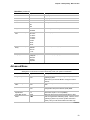
Server Features (continued)
Feature
Comment
I/O baseboard
One 16-bit ISA expansion slot shares a common chassis I/O expansion
slot with a 32-bit PCI slot (you can use the shared slot for either ISA or
PCI but not both).
Six 32-bit PCI expansion slots; one of them shares a common chassis
I/O expansion slot with the ISA slot (you can use the shared slot for
either PCI or ISA but not both).
Five 64-bit PCI expansion slots.
Integrated Cirrus Logic GD5446 VisualMedia† PCI super video
graphics array (SVGA) controller with 2 MB of video memory.
Adaptec AIC†-7880 SCSI-III controller for SCSI devices such as tape,
CD-ROM, and DVD drives installed in the 5.25-inch user-accessible
drive bays.
Diskette controller that supports two drives.
PCI-enhanced Integrated Drive Electronics (IDE) interface that
supports two IDE buses.
PS/2†-compatible keyboard/mouse controller.
Two universal serial bus (USB) ports.
I/O riser card
This card contains all legacy I/O connections; it plugs into a card edge
connector on the I/O baseboard.
PS/2-compatible keyboard and mouse ports (these are
interchangeable).
PS/2-compatible parallel port.
Analog VGA†, 15-pin video port.
Two PS/2-compatible, 9-pin serial ports.
22
AHA†-3940AUW MultiChannel†
PCI-to-UltraSCSI controller card
This card is installed in one of the 32-bit PCI expansion slots on the I/O
baseboard. The AHA-3940AUW provides a 16-bit interface between
the PCI bus and the dual channel SCSI hot-docking backplane.
Interconnect backplane
The backplane electrically connects the I/O and CPU baseboards by
common fast 16-bit expander buses.
SCSI hot-docking backplane
This backplane supports hot-swapping of SCA type SCSI drives,
mounted in carriers, in and out of the hot-docking bays.
Power distribution backplane
This backplane serves as an interface between the power supplies, the
interconnect backplane, and the SCSI hot-docking backplane. The
power distribution backplane distributes the power load of the server
among three or four 420 watt autoranging power supplies.
Chapter 1 Introduction to the High-performance Server
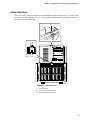
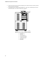
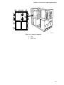
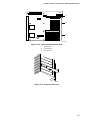
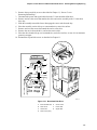
Chassis
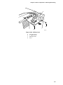
Figures 1-2 and 1-3 show the major components of the server.
A
I
B
H
A
B
C
D
E
F
G
H
I
CPU baseboard and processors
Two, three-fan arrays
Memory modules
3.5-inch SCSI hot-docking bays
SCSI hot-docking backplane
Power distribution backplane
Power supplies
Expansion slots
I/O panel
C
D
E
G
F
OM06706
Figure 1-2. Server, Back/Left Side View
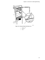
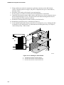
A
L
B
C
D
K
J
E
I
A
B
C
D
E
F
G
H
I
J
K
L
3.5-inch boot drive bay
Interconnect backplane
I/O baseboard
I/O panel
Expansion slots
Power supplies
Power distribution backplane
SCSI hot-docking backplane
3.5-inch SCSI hot-docking bays
3.5-inch diskette drive
Three-fan array
5.25-inch half-height bays
H
G
F
OM06707
Figure 1-3. Server, Back/Right Side View
23
AD450NX Server System Product Guide
Controls and Indicators
See Figure 1-4 on page 25.
Item
Feature
Description
Front Panel
A
Front panel LCD
It displays information about processor type and failure codes.
B
NMI switch
When pressed, it causes a nonmaskable interrupt. This switch is
recessed behind the front panel to prevent inadvertent activation. It
must be pressed with a narrow tool (not supplied).
C
Power LED (green)
When lit continuously, it indicates the presence of DC power in the
server. It goes out when the power is turned off or the power source
is disrupted.
D
Power fault LED (yellow)
When lit continuously, it indicates a power supply failure. When
flashing, it indicates a 240 VA overload shutdown and power control
failures.
E
Cooling fault LED (yellow)
When flashing, it indicates a fan failure has been detected in the
server.
F
Drive fault LED (yellow)
When lit continuously, it indicates an asserted fault status on one or
more hard disk drives in the hot-docking bay. When flashing, it
indicates drive reset in progress.
G
Power switch
When pressed, it turns on or off the DC power inside the server.
H
Reset switch
When pressed, it resets the server and causes the power-on self test
(POST) to run.
CD-ROM Drive
I
Headphone jack
It provides a connection for headphones or speakers.
J
Volume control
It adjusts the volume of headphones or speakers.
K
Activity LED
When lit, it indicates the drive is in use.
L
Open/close button
When pressed, it opens or closes the CD tray.
Security Key Lock
M
Two-position lock
It secures the front doors of the bezel.
3.5-inch Diskette Drive
N
Activity LED
When lit, it indicates the drive is in use.
O
Ejector button
When pressed, it ejects the diskette.
Status LEDs for SCSI Drives in Hot-docking Bays
24
P
Drive power LED (green)
When lit continuously, it indicates the presence of the drive and power
on the drive.
Q
Drive activity LED (green)
When flashing, it indicates drive activity.
R
Drive fault LED (yellow)
When lit continuously, it indicates an asserted fault status on one or
more hard disk drives in the hot-docking bay. When flashing, it
indicates drive reset in progress.
Chapter 1 Introduction to the High-performance Server
A
B
CDE F
I JK
L
N
M
G
H
O
P
Q
R
OM06195
Figure 1-4. Server Controls and Indicators
25
AD450NX Server System Product Guide
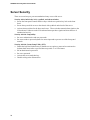
Server Security
There are several ways to prevent unauthorized entry or use of the server.
Security with a built-in key lock, a padlock, and alarm switches:
• Secure the front panel controls and drive bays with the two-position key lock on the front
bezel.
• Secure the top and side covers to the chassis with a padlock on the back of the server.
• Activate alarm switches for the doors and covers. These switches transmit alarm signals to the
I/O baseboard. Software on the I/O baseboard intercepts these signals and alerts the user of
unauthorized activity.
Security with the Setup utility:
• Set server administrative and user passwords.
• Set secure mode to prevent keyboard or mouse input and to prevent use of the front panel
controls.
Security with the System Setup Utility (SSU):
• Enable the keyboard lockout timer so that the server requires a password to reactivate the
keyboard and mouse after a specified time-out period—1 to 120 minutes.
• Set an administrative password.
• Set a user password.
• Activate the secure mode hot-key.
• Disable writing to the diskette drive.
26
Chapter 1 Introduction to the High-performance Server
Front Bezel Key Lock Features
The two-position lock in the front panel bezel lets you lock and unlock the server doors.
• Door 1—provides access to the drives in the 3.5- and 5.25-inch bays and the reset, power
on/off, and NMI switches.
• Doors 2 and 3—provide access to the hot-swappable drives in the 3.5-inch hot-docking bays.
A
B
C
OM06198
Figure 1-5. Front Bezel Security Key Lock
A
B
C
Not used
Locked position
Unlocked position
27
AD450NX Server System Product Guide
Back of Chassis Padlock
A padlock—not provided—can be inserted through the metal loop on the back of the chassis to
prevent access to the CPU and I/O baseboard areas of the server. The mechanical design of the top
and side covers allows one padlock to secure all three of them. (The top cover must be removed
before the side covers can be removed.)
A
OM06194
Figure 1-6. Top and Side Covers Security Padlock
28
Chapter 1 Introduction to the High-performance Server
Alarm Switches
The server has three alarm switches to prevent unauthorized entry into the server. A switch on the
front panel board monitors the top cover. Two switches on the hot-docking backplane monitor the
the doors to the hot-docking bays.
A
B
C
OM06778
Figure 1-7. Alarm Switches
A
B
C
Top cover switch
Left hot-docking bay door switch
Right hot-docking bay door switch
29
AD450NX Server System Product Guide
Password Protection
BIOS passwords prevent unauthorized tampering with the server. If you set the user password, but
not the administrative password, the BIOS requires you to enter the user password before you can
boot the server or run the SSU. If you set both passwords, entering either password lets you boot
the server or enable the keyboard and mouse. Only the administrative password lets you change
the server configuration with the flash-resident Setup utility.
Secure Boot Mode
The secure boot mode allows the server to boot and run the operating system (OS). However, you
cannot use either the keyboard or the mouse until you enter the user password.
You can use Setup to put the server in the secure boot mode. If the BIOS detects a disk in the
CD-ROM drive or a diskette in drive A at boot time, it prompts you for a password. When you
enter the password, the server boots from the disk in the CD-ROM drive or the diskette in drive A.
Entering a password also disables the secure mode.
If there is no disk in the CD-ROM drive or diskette in drive A, the server boots from drive C. It
automatically goes into secure mode. All enabled secure mode features go into effect at boot time.
If you set a hot-key combination, you can secure the server immediately.
Boot Sequence Control
The BIOS security features determine the boot devices and the boot sequence. They also control
disabling writes to the diskette drive in secure mode. You can use the SSU to select each boot
device. The default boot sequence is diskette, hard disk, CD-ROM, and Network.
Boot Without Keyboard
The server can boot with or without a keyboard. Before it boots, the BIOS displays a message
about the keyboard stating whether or not it detects one. During POST, the BIOS automatically
detects and tests the keyboard if it is present.
Locked Power and Reset Switches
The power and reset push-button switches on the front panel are locked when the server is in the
secure mode. To exit from the secure mode, you must enter your user password.
Diskette Write Protect
If Diskette Write Protect is enabled in Setup, it write-protects the diskette drive only while the
server is in the secure mode. To exit from the secure mode, you must enter your user password.
30
Chapter 1 Introduction to the High-performance Server
Video Blanking
If Video Blanking is enabled in Setup, the video display will be off when the server is in the secure
mode. To exit from the secure mode, you must enter your user password.
31
This page should be blank
2 On-site Installation: Installing the Server
This chapter tells how to
• Select a site
• Connect input and output devices
• Turn on the server and create installation diskettes from the Server System Configuration
Software CD
• Read and print a copy of this manual
• Exit to DOS
WARNING
To avoid personal injury when moving the server from one location to
another, use only a mechanical assist unit to move it. The minimum
server configuration weighs about 58 kg (128 lbs), and the maximum
one weighs close to 79 kg (175 lbs).
Do not attempt to lift or move the server by the handles on the power
supplies.
Selecting a Site
The server operates reliably within the specified environmental limits (see page 34). Choose a site
that is
• Near a grounded power outlet
In the United States and Canada, this means a NEMA 5-15R outlet for 100-120 V~ or a
NEMA 6-15R outlet for 200-240 V~.
For international sites, this means a grounded power outlet applicable for the electrical
code of the region.
CAUTION
•
•
•
•
•
Ensure that the power service connection is through a properly grounded
outlet.
Clean and dust-free
Well ventilated and away from sources of heat
Isolated from strong electromagnetic fields and electrical noise caused by electrical devices
such as air conditioners, large fans, large electric motors, radio and TV transmitters, and high
frequency security devices
Spacious enough to provide sufficient room behind and around the server so that you can
remove AC power from it by unplugging the power cord from each power supply or wall
outlet
Away from sources of vibration or physical shock
33
AD450NX Server System Product Guide
Physical Specifications
*
Height
69.85 cm (27.5 inches)
Width
43.18 cm (17.0 inches)
Depth
71.12 cm (28.0 inches)
Weight
58 kg (128 lbs) minimum configuration; 79 kg (175 lbs) maximum configuration
Front clearance*
30.5 cm (12.0 inches)
Side clearance*
7.6 cm (3.0 inches)
Rear clearance*
15.2 cm (6.0 inches)
This is the minimum clearance required for server cooling and airflow; additional clearance is required for servicing.
Environmental Specifications
Temperature
Nonoperating
Operating
–40° to 70 °C (–40° to 158 °F)
5° to 35 °C (41° to 95 °F); derated 0.5 °C for every 1000 ft (305 m)
Humidity
Operating wet bulb
Nonoperating
Operating
Not to exceed 33 °C (91.4 °F) (with diskette drive or hard disk drive)
95% relative humidity (noncondensing) at 55 °C (131 °F)
85% relative humidity (noncondensing) at 35 °C (95 °F)
Nonoperating
Operating
20 g, 11 msec, 1/2 sine
2.0 g, 11 msec, 1/2 sine
Nonoperating
Operating
To 50,000 ft (15,240 m)
To 10,000 ft (3,048 m)
Shock
Altitude
Acoustic noise
Typically <50 dBA at 28 °C (82 °F) with four internal hard disk drives
(measured at 1 meter from the front of the server with the peripherals
idle). The noise of the variable-speed power supply fans will increase with
temperature and power load. Your selection of peripherals may change
the noise level.
Electrostatic discharge (ESD)
Tested to 20 kilovolts (kV), no component damage. (CD-ROM drive
tested to 15 kV, manufacturer’s specification.)
AC Input Power
100-120 V~
200-240 V~
Single power supply, fully loaded
100-120 V~, 7.0 A, 50/60 Hz
200-240 V~, 3.5 A, 50/60 Hz
After Unpacking the Server
Inspect the shipping box for evidence of mishandling during transit. If the shipping box is
damaged, photograph it for reference. After removing the contents, keep the damaged box and the
packing materials. If the contents appear damaged, file a damage claim with the carrier
immediately.
Save the shipping boxes and packing materials to repackage the server in the event you decide to
move it to another site.
34
Chapter 2 On-site Installation: Installing the Server
Moving the Server
The front casters on the base of the server are locked to prevent the server from moving.
1. Using your finger, pull the hinged plastic locks to the open position to unlock the front casters.
2. After you connect peripheral devices, cables, and power cords to the server, slide the server in
to its operating position.
3. Push the plastic locks to the closed position to lock the front casters.
A
B
C
OM06775
Figure 2-1. Server Casters
A
B
C
Hinged plastic caster lock
Closed
Open
35
AD450NX Server System Product Guide
Connecting Peripheral Devices
CAUTION
Before connecting peripheral devices to the server, verify that the power
cords are unplugged from the power supplies. Otherwise, equipment
damage can result.
Only a qualified service technician is authorized to remove the server
covers and to access any of the components inside the server.
If your server normally operates without a video monitor and keyboard—for example, as a
network server—you must install them to configure it. You may remove them after running the
SSU. See Chapter 5, “System Setup Utility: When to Run” for information about running this
utility.
Connect your keyboard, mouse, monitor, and other peripheral devices after a qualified service
technician installs internal options. See Figure 2-2.
36
Keyboard and Mouse
Connect the signal cable of a PS/2-compatible keyboard or mouse to either one
of the 6-pin miniature Deutsche Industrie Norm (DIN) connectors on the server
back panel. The BIOS detects and initializes the keyboard and mouse ports
accordingly. Each port is overcurrent protected by a 1-ampere positive
temperature coefficient (PTC) resistor.
Monitor
Connect the signal cable of the video monitor to the 15-pin connector of the
Super VGA port on the back panel.
Other Devices
Connect other external peripheral devices by following the manufacturer’s
documentation. The back panel also provides two serial ports, a parallel port,
and two USB ports. The back of the chassis provides two Intelligent Chassis
Management Bus (ICMB) ports.
Chapter 2 On-site Installation: Installing the Server
A
B
E
D
C
G
F
H
I
OM06193
Figure 2-2. Server I/O Panel
A
B
C
D
E
F
G
H
I
PS/2-compatible serial port 1 (COM1), 9-pin RS-232 connector
PS/2-compatible parallel port (LPT), 25-pin bidirectional subminiature D connector
USB ports O and 1, 4-pin connectors
Super VGA compatible, 15-pin video connector
PS/2-compatible serial port 2 (COM2), 9-pin RS-232 connector
PS/2-compatible keyboard port, 6-pin connector
PS/2-compatible mouse port, 6-pin connector
Intelligent Chassis Management Bus (ICMB) port 1, SEMCONN† 6-pin connector
Intelligent Chassis Management Bus (ICMB) port 2, SEMCONN 6-pin connector
37
AD450NX Server System Product Guide
Obtaining Power Cords
WARNING
Do not attempt to modify or use AC power cords that are not the exact
type required.
Because power cords are not supplied for the server power supplies, you must obtain power cords
that meet the following criteria:
• The cord must be rated for the available AC voltage and have a current rating that is at least
125% of the current rating of the server.
• The connector that plugs into the wall outlet must be a grounding-type plug designed for use in
your region. It must have certification marks showing certification by an agency acceptable in
your region.
• The connector that plugs into the AC receptacle on the server power supply must be an
IEC 320, sheet C13, type female connector.
• The cord must be less than 4.5 meters (14.76 feet) long, and it must be flexible <HAR>
(harmonized) or VDE certified cordage to comply with the server safety certifications.
Turning on Your Server
WARNING
1.
2.
3.
4.
✏
The push-button on/off power switch on the front panel of the server
does not turn off the AC power. To remove AC power from the server,
you must unplug each power cord from each power supply or wall
outlet.
Make sure all external devices, such as a video monitor, keyboard, and mouse (optional) have
been connected.
Remove drive protection cards (if present) from the removable media drives.
Turn on your video monitor.
For each power supply present in the server, plug the female end of a power cord into the
power supply input receptacle on the back of the chassis (your server may be configured with
either three or four power supplies).
NOTE
To plug in a power cord, push and hold the spring-loaded safety interlock
mechanism toward the edge of the power supply. Then plug the power cord
into the exposed inlet receptacle, and release the safety interlock.
5. For each power supply present in the server, plug the power cord into a properly grounded
power outlet. See page 33 for power outlet requirements.
38
Chapter 2 On-site Installation: Installing the Server
E
PS
F
I
A
B
C
D
OM06196
Figure 2-3. Power Supplies With Safety Interlocks
A
B
C
D
E
F
Four Power Supplies (fourth power supply is redundant)
AC power inlet receptacle and safety interlock mechanism
Handle for removing the power supply
Four screws
PS LED (green) power supply okay
When lit, indicates the power supply is on and working. When off, it may indicate
either that the power supply has failed, the system-loading on the power supply is too
low to detect failure, or the supply is not properly plugged in.
I LED (green) power supply current OK
When lit, indicates power supply is on and OK. When off, indicates the power supply
has shut down because of an overcurrent condition or the power supply has failed.
39
AD450NX Server System Product Guide
6. If the server does not come on when you plug the power cords into the power outlets, press the
power switch on the front panel.
7. Verify that the power-on light on the front panel is lit. After a few seconds the power-on self
test (POST) begins. See “Power-on Self Test” on page 41.
A
B CDE F
G
H
OM06772
Figure 2-4. Server Power and Reset Switches
A
B
C
D
E
F
G
H
40
Front panel LCD
NMI switch
Power LED (green)
Power fault LED (yellow)
Cooling fault LED (yellow)
Drive fault LED (yellow)
Power switch
Reset switch
Chapter 2 On-site Installation: Installing the Server
Power-on Self Test
Each time you turn on the server the power LED on the front panel turns on and the power-on self
test (POST) starts running. POST checks the I/O system board, processor system board, keyboard,
and most installed peripheral devices.
During the memory test, POST displays the amount of memory that it is able to access and test.
Depending on the amount of memory installed on each memory board, the test may take several
minutes.
These screen prompts and messages appear after the memory test:
Mouse initialized....
Keboard detected
Press <F2> to enter SETUP
Do NOT press <F2>. The above message remains for a few seconds, and POST continues. The
server beeps once, and this message appears:
Operating system not found
Go to “Booting From the Server Configuration Software CD” on page 42.
41
AD450NX Server System Product Guide
Booting From the Server Configuration Software CD
CAUTION
The Server Configuration Software CD contains only a limited operating
system. This limited operating system provides enough function to let you
boot from the CD and copy and use the utility and manual files from the CD.
But this limited OS is NOT intended to be copied onto diskettes or onto your
hard disk as a full-function OS that supports networking or Windows†. To
run your server and applications, you must buy the OS of your choice and
install it on the server.
See Figure 2-5.
1. Open the CD tray by pressing the open/close button on the front panel of the CD-ROM drive—
the tray will slide out of the drive.
2. Open the CD case. Press down on the center hub of the case with your finger to release the
hub tension on the CD.
CAUTION
Handle the CD only by the inner and outer edges. Do not touch the data side
of the CD—the side without the label.
3. Gently grasp the center hole and outer edge of the CD, remove it from the case, and place it
label-side up in the tray.
4. Press the open/close button or gently push on the tray—it will automatically slide into the
drive.
A
B
OM06774
Figure 2-5. CD-ROM Drive
A
B
Open/close push-button switch
CD tray
5. Press the reset switch on the front panel to reboot the server.
6. When POST completes, the server beeps once, boots from the CD, installs a mouse driver, and
displays the CD-ROM menu. Use the arrow keys to scroll through the menu bar and to view
the tasks in the pop-up menus.
42
Chapter 2 On-site Installation: Installing the Server
✏
NOTE
If you do not see the CD-ROM menu but see the following message instead,
you need to change the “Boot Device Priority” to the CD-ROM. See
“Server Won’t Boot From the CD” on page 44 for instructions.
Operating system not found
Copying Configuration Software to Diskettes
When you copy software from the CD onto diskettes, device drivers suitable for several different
operating systems are copied onto the diskettes. However, your operating system will read only
those drivers it can recognize, so you cannot usually check the directory of a diskette that is not
formatted for your operating system. Instead, you may see a message to the effect, “disk not
formatted, do you want to format it now?” Don’t worry; the drivers for YOUR operating system
should be present on the diskette and available for you to load on the system.
1. Before starting, make sure that you have on hand several blank high-density diskettes.
2. From the CD-ROM menu bar, select Create Diskettes and press <Enter>.
3. Follow the prompts to copy the software onto the diskettes.
4. When finished, select Quit to DOS (on the CD-ROM menu bar), and press <Enter>.
5. Remove the CD from the drive.
Installing Video Drivers
After configuring the server, you can install various video drivers to take full advantage of the
enhanced features provided by the onboard Cirrus Logic GD5446 PCI VisualMedia accelerator.
The server may not operate properly without these drivers installed.
After copying the drivers from the Configuration Software CD to diskettes, read the
README.TXT file on the Display Drivers and DOS Utilities diskette. The .TXT file contains the
most current information about which video drivers you need to install on your server. Follow the
installation instructions in the README.TXT file.
To install these drivers, do this:
1. Fully configure your server. (This can include adding application software, an ISA add-in
board, PCI add-in boards, and the like.)
2. Insert disk 1 of the video drivers and utilities for MS-DOS† and Windows into drive A.
3. At the DOS command prompt, type A:install and press <Enter>.
4. Follow the onscreen directions to install the video drivers.
Installing SCSI Drivers
After copying the SCSI drivers from the Configuration Software CD to diskettes, follow the
instructions in the README.TXT file on the first diskette to install the drivers.
43
AD450NX Server System Product Guide
Server Won’t Boot From the CD
It is possible that your server was shipped with the diskette drive or another device set as the first
boot device. If so, the server will try to boot from a diskette or other device rather than from the
CD we have provided. By pressing <Esc> during POST, you can override the boot sequence
specified in Setup by selecting a different primary boot device. This override is valid only for that
specific boot. Subsequent boots revert back to the sequence specified in Setup. If the chosen
device fails to load the operating system, the BIOS reverts to the previous boot sequence. The
<Esc> hot key is valid while the “Press <F2> key to enter Setup” message is displayed on the
screen. At the end of POST, if the <Esc> key was pressed, a pop-up boot menu is displayed. It
allows you to change the boot sequence, or to enter Setup and permanently change the sequence.
To override the boot sequence, do this:
1. Press the reset switch on the front panel to reboot the server—the CD can be in the drive or
not.
2. When POST displays this message:
Press <F2> to enter SETUP
3. Press <Esc> and wait for the following boot menu to display:
OM08360
Figure 2-6. Boot Menu
4. From the boot menu, select the CD-ROM drive, and press <Enter>.
5. When you see the following pop-up menu, press <Enter> to boot from the CD.
OM08361
Figure 2-7. CD-ROM Boot Menu
44
Chapter 2 On-site Installation: Installing the Server
The server should now boot from the CD, displaying a menu bar that includes creating diskettes,
diagnostics, reading/printing the manual, and quitting to DOS.
CAUTION
If the server does not operate as described in this chapter, contact a qualified
service technician.
45
This page should be blank
3 Power-on Self Test: Description/Running
Power-on Self Test
WARNING
The push-button on/off power switch on the front panel of the server
does not turn off the AC power. To remove AC power from the server,
you must unplug each AC power cord from each power supply or wall
outlet.
Each time you turn on the server the power LED on the front panel turns on and POST starts
running. It checks the I/O baseboard, CPU baseboard, keyboard, and most installed peripheral
devices. During the memory test, POST displays the amount of memory that it is able to access
and test. Depending on the amount of memory installed on the memory module, it may take
several minutes to complete the memory test.
Turn on your video monitor and server. After a few seconds the power-on self test (POST) begins.
You can enter Setup when POST displays this message:
Press <F2> to enter SETUP
If you press <F2>, follow the instructions on the monitor when Setup appears.
✏
NOTE
Because POST must complete test and initialization functions after pressing
<F2>, a few seconds may pass before entering Setup.
If you do not press <F2>, POST continues.
During bootup, the server first recognizes and displays the BIOS banner for the AIC-7880 SCSI
host adapter on the I/O baseboard.
Next, the server recognizes and displays the BIOS banner for the AHA-3940AUW SCSI host
adapter on the add-in board plugged into a 32-bit PCI slot on the I/O baseboard.
When the BIOS banner for each adapter appears, you can run the included SCSISelect utility by
pressing <Ctrl+A> when this message appears:
Press <Ctrl><A> for SCSISelect(TM) Utility!
If you have installed SCSI devices in the server, press <Ctrl+A>. When the utility appears, follow
the instructions on the monitor to configure each host adapter and run the SCSI disk utilities. See
Chapter 6, “SCSISelect Utility: When to Run,” for instructions.
47
AD450NX Server System Product Guide
If POST detects an error, it displays the error code, the server beeps once, and this message
appears:
Press <F2> for Setup, <ESC> to Boot
To enter Setup, Press <F2>. When the Setup utility appears, follow the instructions on the
monitor.
To boot the server, press <ESC>. However, if a drive with bootable media is not detected, the
server beeps once, and this message appears:
Operating System not found
If POST did not detect an error and you choose not to run the SCSISelect Utility, POST continues,
the server beeps once, and this message appears:
Operating System not found
See Chapter 2, “On-site Installation: Installing the Server,” for instructions on creating software
installation diskettes.
If the server halts before POST completes running, it emits a beep code indicating a fatal system
error that requires immediate attention. If POST can display a message on the video monitor, it
causes the speaker to beep twice as the message appears.
Note the screen display and write down the beep code you hear; this information is useful for your
service representative. For a listing of beep codes and error messages that POST can generate, see
Chapter 22, "Solving Problems: Troubleshooting/Error Messages."
48
4 Setup Utility: When to Run
The flash-resident BIOS Setup utility is used to configure I/O baseboard resources. It is stored in
both flash memory (NVRAM) and the battery-backed memory of the real-time clock (RTC) on the
I/O baseboard.
When to Run the BIOS Setup Utility
The BIOS Setup is a flash-based configuration utility that is used to configure onboard resources
and to set user-selectable options such as boot device ordering, keyboard autorepeat, and security.
Use Setup to configure the server into a bootable state, and then use the SSU and other utilities to
further configure the server.
Setup lets you change the server configuration defaults. It does not allow you to enter or change
information about PCI or ISA add-in boards; you must use the SSU instead. Setup stores the
configuration values in flash memory; they take effect when you boot the server. POST checks
these values against the actual hardware configuration; if they do not agree, POST generates an
error message. You must then run Setup to specify the correct configuration.
You can run Setup with or without an operating system being present.
Because values entered using Setup are overwritten when you run the SSU, you should run Setup
only under the following conditions:
• If the diskette drive is disabled
• If the server has a diskette drive that is disabled or improperly configured, use Setup to
configure the server into a bootable state, and then use the SSU and other utilities to further
configure the server. In Setup, you can enable the drive so you can use the SSU. If necessary,
you can disable the diskette drive again after exiting the SSU.
• If the server does not have a diskette drive, or it is disabled, use Setup to configure the server.
• If you have installed only an ISA add-in board in your server
If the server has a properly configured, enabled diskette drive, use the SSU to configure the server.
Information entered using the SSU overrides any entered using Setup.
Running the Setup Utility
You can enter Setup under several conditions:
• when you turn on the server
• when you reboot the server by pressing the push-button reset switch on the front panel
• when you reboot the server by pressing <Ctrl+Alt+Del> while at the DOS operating system
prompt
• when you turn on or reset your server after an orderly shutdown of an operating system other
than DOS
49
AD450NX Server System Product Guide
Each time you turn on or reboot your server POST begins and, after a few seconds, displays this
message:
Press <F2> to enter Setup
After pressing F2, a few seconds may pass before entering Setup while POST completes tests and
initialization functions. When the F2 prompt disappears, pressing F2 will have no effect. When
Setup is entered, the Main Menu options page is displayed.
Use the following keys to navigate through the menus and submenus.
Press
To
F1
Get help about an item
ESC
Go back to a previous item
↑
Select the previous value in a menu option list
↓
Select the next value in a menu option list
←→
Select a major menu
-
Change the value of the current menu item to the previous value
+
Change the value of the current menu item to the next value
Enter
Activate submenus, select feature options, and change feature values
F9
Display the following message:
Setup Confirmation
Load default configuration now?
[Yes]
[No]
The [Yes] button will be highlighted. If you press <Enter>, all Setup fields return to their
default values. If you press <ESC> or select No, the server returns to the configuration it had
before you pressed <F9>, without affecting any existing field values.
F10
Display the following message:
Setup Confirmation
Save configuration changes and exit now?
[Yes]
[No]
The [Yes] button will be highlighted. If you press <Enter>, all current Setup values are
saved, and the system is reset. If you press <ESC> or select No, the server returns to the
configuration it had before you pressed <F10>, without affecting any existing values.
50
Chapter 4 Setup Utility: When to Run
Main Menu
Default values are in bold typeface, and auto-configured values are shaded.
Feature
Option
Description
System Time
HH:MM:SS
Set the System Time. To select a field, press <Tab>,
<Shift + Tab>, or <Enter>. Then type in a new value. If
you replace the battery, the default time is 00:00. (This
is a 24-hour clock.)
System Date
MM/DD/YYYY
Set the System Date. To select a field, press <Tab>,
<Shift + Tab>, or <Enter>. Then type in a new value. If
you replace the battery, the default date is Jan 1990.
Legacy Diskette A:
Disabled
360 KB, 5 ¼”
1.2 MB, 5 ¼”
720 KB, 3 ½”
1.44/1.25 MB, 3 ½”
2.88 MB, 3 ½”
Select the diskette type for drive A:. (The 1.25 MB,
3.5-inch refers to a 1024 byte/sector Japanese media
format. To support the 1.25 MB, 3.5-inch requires a
3.5-inch 3-mode diskette drive.)
Legacy Diskette B:
Disabled
360 KB, 5 ¼”
1.2 MB, 5 ¼”
720 KB, 3 ½”
1.44/1.25 MB, 3 ½”
2.88 MB, 3 ½”
Select the diskette type for drive B: (The size 1.25 MB,
3.5-inch refers to a 1024 byte/sector Japanese media
format. To support the 1.25 MB, 3.5-inch requires a
3.5-inch 3-mode diskette drive.)
Primary Master
CD-ROM
Press <Enter> for options.
Autotype Fixed Disk:
Press <Enter>
Pressing <Enter> attempts to detect the drive type for
drives that comply with ANSI specifications.
Type:
User
Auto
1-39
CD-ROM
User—lets you enter the parameters of the hard disk
drive installed at this connection.
ATAPI Removable
Auto—autotypes the hard disk drive installed here.
1-39—lets you select the predetermined hard disk drive
installed here.
CD-ROM—a CD-ROM is installed here.
ATAPI Removable—removable disk drive installed here.
Multi-sector Transfers:
Disabled
LBA Mode Control
Disabled
32-bit I/O:
Disabled
Enabled
Transfer Mode
Standard
Ultra DMA Mode:
Disabled
Primary Slave
None
Press <Enter> for options.
Autotype Fixed Disk:
Press <Enter>
Pressing <Enter> attempts to detect the drive type for
drives that comply with ANSI specifications.
Enabled allows 32-bit IDE data transfers.
continued
51
AD450NX Server System Product Guide
Main Menu (continued)
Feature
Option
Description
Type:
User
Auto
1-39
CD-ROM
User—lets you enter the parameters of the hard disk
drive installed at this connection.
ATAPI Removable
Auto—autotypes the hard disk drive installed here.
1-39—lets you select the predetermined hard disk drive
installed here.
CD-ROM—a CD-ROM is installed here.
ATAPI Removable—removable disk drive installed here.
Enabled allows 32-bit IDE data transfers.
32-bit I/O:
Disabled
Enabled
Ultra DMA Mode:
Disabled
Secondary Master
None
Press <Enter> for options.
Autotype Fixed Disk:
Press <Enter>
Pressing <Enter> attempts to detect the drive type for
drives that comply with ANSI specifications.
Type:
User
Auto
1-39
CD-ROM
User—lets you enter the parameters of the hard disk
drive installed at this connection.
ATAPI Removable
Auto—autotypes the hard disk drive installed here.
1-39—lets you select the predetermined hard disk drive
installed here.
CD-ROM—a CD-ROM is installed here.
ATAPI Removable—removable disk drive installed here.
Enabled allows 32-bit IDE data transfers.
32-bit I/O:
Disabled
Enabled
Ultra DMA Mode:
Disabled
Secondary Slave
None
Press <Enter> for options.
Autotype Fixed Disk:
Press <Enter>
Pressing <Enter> attempts to detect the drive type for
drives that comply with ANSI specifications.
Type:
User
Auto
1-39
CD-ROM
User—lets you enter the parameters of the hard disk
drive installed at this connection.
ATAPI Removable
Auto—autotypes the hard disk drive installed here.
1-39—lets you select the predetermined hard disk drive
installed here.
CD-ROM—a CD-ROM is installed here.
ATAPI Removable—removable disk drive installed here.
32-bit I/O:
Disabled
Enabled
Ultra DMA Mode:
Disabled
Processor Information
Press <Enter>
Processor 1
Enabled allows 32-bit IDE data transfers.
Displays information about all processors. You cannot
modify any items in this menu. Consult your system
administrator if an item requires changing.
Stepping ID 2.
Processor 1
L2 cache size [512 KB].
Processor 2
Stepping ID, absent or disabled.
continued
52
Chapter 4 Setup Utility: When to Run
Main Menu (continued)
Feature
Option
Description
Processor 3
Stepping ID, absent or disabled.
Processor 4
Stepping ID, absent or disabled.
Keyboard Features
Press <Enter> for options.
Numlock:
Auto
On
Off
Select power-on state for numlock.
Key Click:
Disabled
Enabled
Enabled produces the key click.
Keyboard auto-repeat
rate:
30/sec
26.7/sec
21.8/sec
18.5/sec
13.3/sec
10/sec
6/sec
2/sec
Select key repeat rate.
Keyboard auto-repeat
delay:
1/4 sec
1/2 sec
3/4 sec
1 sec
Select delay before key repeat.
Language
English (US)
Français
Deutsch
Italiano
Español
Select the display language for the BIOS.
Advanced Menu
Setup Warning
Setting items on this menu to incorrect values may cause your system to malfunction.
Feature
Option
Description
Plug & Play O/S:
No
Yes
Select Yes if you are using a Plug and Play capable
operating system.
Select No if you need the BIOS to configure nonboot
devices.
Reset Configuration
Data:
No
Yes
Select Yes if you want to clear the system configuration
data.
Enable ACPI
No
Yes
Select Yes if you want to enable the advanced
configuration and power interface (ACPI) BIOS.
Use Multiprocessor
Specification
1.1
1.4
Configure the Multiprocessor Specification revision level.
Some OSs require 1.1 for compatibility.
Large Disk Access
Mode
CHS
LBA
Select the drive access method for IDE drives. Most
OSs use logical block addressing (LBA). However, some
operating systems may use the cylinder head sector
(CHS). See your OS documentation for further help.
continued
53
AD450NX Server System Product Guide
Advanced Menu (continued)
Feature
Option
Description
Pause Before Boot
Disabled
Enabled
Pause five seconds before booting the OS.
PCI Configurations
Additional Setup menus to configure PCI devices.
PCI Device,
Embedded SCSI A
Setup items for configuring the specific PCI device.
Option ROM Scan:
Enabled
Disabled
Initialize device expansion ROM.
Enable Master:
Enabled
Disabled
Enable selected device as a PCI bus master.
Latency Timer:
Default
0020h
0040h
0060h
0080h
00A0h
00C0h
00E0h
Allot minimum guaranteed time slice for bus master in
units of PCI bus clocks.
Option ROM Scan:
Enabled
Disabled
Initialize device expansion ROM.
Enable Master:
Enabled
Disabled
Enable selected device as a PCI bus master.
Latency Timer:
Default
0020h
0040h
0060h
0080h
00A0h
00C0h
00E0h
Allot minimum guaranteed time slice for bus master in
units of PCI bus clocks.
Disabled
Enabled
Auto
Configure serial port A using these options:
PCI Devices
I/O Device
Configuration
Serial Port A
•
Disabled—no configuration.
•
Enabled—user configuration.
•
Auto—BIOS or OS chooses the configuration.
•
OS Controlled—displayed when controlled by
the OS.
Base I/O Address
3F8
2F8
3E8
2E8
Set the base I/O address for serial port A.
Interrupt
IRQ3
IRQ4
Set the interrupt for serial port A.
continued
54
Chapter 4 Setup Utility: When to Run
Advanced Menu (continued)
Feature
Option
Description
Serial Port B
Disabled
Enabled
Auto
Configure serial port B using these options:
•
Disabled—no configuration.
•
Enabled—user configuration.
•
Auto—BIOS or OS chooses the configuration.
•
OS Controlled—displayed when controlled by
the OS.
Base I/O Address
3F8
2F8
3E8
2E8
Set the base I/O address for serial port B.
Interrupt
IRQ3
IRQ4
Set the interrupt for serial port B.
Parallel Port
Disabled
Enabled
Auto
Configure the parallel port using these options:
•
Disabled—no configuration.
•
Enabled—user configuration.
•
Auto—BIOS or OS chooses the configuration.
•
OS Controlled—displayed when controlled by
the OS.
Mode
Output only
Bidirectional
EPP
ECP
Set the mode for the parallel port.
Interrupt
IRQ5
IRQ7
Set the interrupt for the parallel port.
Diskette Controller
Disabled
Enabled
Auto
Configure the diskette controller using these options:
Base I/O Address
•
Disabled—no configuration.
•
Enabled—user configuration.
•
Auto—BIOS or OS chooses the configuration.
•
OS Controlled—displayed when controlled by
the OS.
Primary
Secondary
Set the base I/O address for the diskette controller.
Disabled
Enabled
Enabled automatically sets two-way or four-way
permuting based on the memory configuration. Enabled
requires
Advanced Chip Set
Control
Address Bit Permuting
Card to Card
Interleave
Disabled
Enabled
•
number of rows to be a power of two.
•
all rows to be the same size.
•
all populated rows to be adjacent and start at row 0.
Enabled requires a symmetric RAM configuration
between two memory modules.
continued
55
AD450NX Server System Product Guide
Advanced Menu (continued)
56
Feature
Option
Description
Base RAM Step
1 MB
1 KB
Every location
Tests base memory once per MB or once per KB or
every location.
Extended RAM Step
1 MB
1 KB
Every location
Tests extended memory once per MB or once per KB or
every location.
L2 Cache
Disabled
Enabled
Enabled causes the secondary cache to be sized and
enabled. Disabled causes the L2 cache to be disabled
for core clock frequency bus ratios equal to 2.
ISA Expansion
Aliasing
Disabled
Enabled
Enabled causes every I/O access with an address in the
range of x100h-x3FFh, x500h-x7FFh, x900h-xBFFh, and
xD00h-xFFFh to be internally aliased to the range 0100h03FFh before performing any other address range
checking.
Memory Scrubbing
Disabled
Enabled
Enabled lets the BIOS automatically detect and correct
single-bit memory errors.
Restreaming Buffer
Disabled
Enabled
When enabled, the data returned and buffered for a
delayed inbound read may be reaccessed following a
disconnect.
Read Prefetch for
PXB0A
16
32
64
Configures the number of “Dwords” that will be
prefetched on memory read multiple commands.
Read Prefetch for
PXB0B
16
32
64
Configures the number of “Dwords” that will be
prefetched on memory read multiple commands.
Read Prefetch for
PXB1A
16
32
64
Configures the number of “Dwords” that will be
prefetched on memory read multiple commands.
Multiboot Support
Disabled
Enabled
Only enable when the total number of bootable devices
is less than eight.
Special VGA Devnode
Disabled
Enabled
Enable this node only when nonPCI compliant VGA
cards need to be debugged. Enabling will impact I/O
resources for a large configuration.
Chapter 4 Setup Utility: When to Run
Security Menu
Feature
Option
Description
User Password Is
Clear
When you enter your user password, this field
automatically changes to set.
Administrator
Password Is
Clear
When you enter your administrator password, this field
automatically changes to set.
Set User Password
Enter
The user password controls access to the system at
boot. To enter a password, press <Enter> and follow the
screen prompts.
Set Administrator
Password
Enter
The administrator password controls access to the setup
utility. To enter a password, press <Enter> and follow
the screen prompts.
Password on Boot
Disabled
Enabled
Requires password entry before boot. The system
remains in the secure mode until you enter the password.
Password on Boot takes precedence over Secure Mode
Boot.
Diskette Access
User
Administrator
Controls access to diskette drives.
Secure Mode Timer
Disabled
1 min
2 min
5 min
10 min
20 min
1 hr
2 hr
Select the time-out period of keyboard or mouse
inactivity required before the secure mode activates.
(A password must be entered for the secure mode to
work.)
Secure Mode Hot Key
[]
Select a hot key, and then press <Ctrl+Alt+(your hot key)
to place the system in the secure mode. The key should
not conflict with any application. Available choices are AZ and 0-9. Press <Del> to remove the hot key.
Secure Mode Boot
Disabled
Enabled
Enabled lets the system boots in the secure mode.
Requires a password to unlock the system.
Video Blanking
Disabled
Enabled
Enabled blanks video when the secure mode activates.
Requires a password to unlock the system.
Diskette Write Protect
Disabled
Enabled
Enabled write protects the diskette drive when the
Secure Mode activates. Requires a password to restore
the diskette writes.
Front Panel Lockout
Disabled
Enabled
Enabled disables the front panel controls when the
Secure Mode activates. Requires a password to unlock
the system.
57
AD450NX Server System Product Guide
Server Menu
Feature
Option
System Management
Description
An additional setup menu for changing server
management features.
Firmware SMIs
Disabled
Enabled
Disabled turns off all firmware SMI sources.
System Event Logging
Disabled
Enabled
Enabled logs critical system events.
Clear Event Log
Disabled
Enabled
Enabled cleans the system event log.
Assert NMI on AERR
Disabled
Enabled
Enabled generates an NMI. Enabling the Firmware SMIs
option is required to assert an NMI.
Assert NMI on BERR
Disabled
Enabled
Enabled generates an NMI. Enabling the Firmware SMIs
option is required to assert an NMI.
Assert NMI on PERR
Disabled
Enabled
Enabled generates an NMI. Enabling the SERR option is
required to activate this option.
Assert NMI on SERR
Disabled
Enabled
Enabled generates an NMI.
Enable Host Bus Error
Disabled
Enabled
Enables host single- and multi-bit errors.
Server Management
Information
Displays system serial number, part number, and server
management controller revisions. All items on this menu
cannot be modified in user mode. If any items require
changes, please consult your system administrator.
Board Part Number
Information only.
Board Serial Number
Information only.
System Part Number
Information only.
System Serial Number
Information only.
Chassis Part Number
Information only.
Chassis Serial
Number
Information only.
BMC Revision
Information only.
FPC Revision
Information only.
Primary HSBP
Revision
Information only.
Secondary HSBP
Revision
Information only.
Console Redirection
Additional setup menus to configure the console.
COM Port Address
Disabled
3F8
2F8
3E8
IRQ #
None
Select the port address. Make sure these values are
identical to those of serial ports A and B in the peripheral
configuration setup menu.
continued
58
Chapter 4 Setup Utility: When to Run
Server Menu (continued)
Feature
Option
Description
Baud Rate
9600
19.2 K
38.4 K
115.2 K
Select the baud rate.
Flow Control
No Flow Control
CTS/RTS
XON/XOFF
CTS/RTS + CD
Select the flow control.
•
CTS/RTS = Hardware
•
XON/XOFF = Software
•
CTS/RTS + CD = Hardware + carrier detect for
modem use.
Processor Retest
No
Yes
Yes causes the BIOS to clear historical processor status
and retest all processors on the next boot.
EMP Password Switch
Disabled
Enabled
Enable or disable the EMP password.
EMP ESC Sequence
The front panel controller firmware updates this field.
EMP Hangup Line
String
The front panel controller firmware updates this field.
Modem Init String
This string accepts up to 16 characters. The upper four
characters will go to the next field which will pop up as
soon as the 16th character is filled. Trying to fill the 17th
character in the same field will have a wraparound
problem.
EMP Access Mode
Preboot Only
Always Active
Disabled
Preboot Only—EMP enabled during power down or
POST.
Always Active—EMP always enabled.
Disabled—EMP disabled.
EMP Restricted Mode
Access
Disabled
Enabled
When enabled, power down, front panel NMI, and reset
control via EMP are disabled. Restricted mode can be
selected with preboot or always active.
EMP Direct
Connect/Modem
Mode
Direct Connect
Modem Mode
You can connect directly to the port or use a modem.
59
AD450NX Server System Product Guide
Boot Menu
Feature
Option
Description
Diskette Check:
Disabled
Enabled
Enabled verifies the diskette type on boot. Disabled
speeds up the boot process.
Boot Device Priority
60
Select the search order for the types of boot devices.
1.
Diskette Drive
2.
Removable
Devices
3.
Hard Drive
4.
ATAPI CD-ROM
Drive
Use the up and down arrow keys to select a device.
Press <+> to move it up the list, and press <-> to move it
down the list. Press <Esc> to exit this menu.
Hard Drive
The system attempts to boot to the OS from the first hard
drive in this list. If it does not find an OS, the system
tries the next drive listed until if finds an OS. Use the up
and down arrow keys to select a device. Press <+> to
move it up the list, and press <-> to move it down the list.
Press <Esc> to exit this menu.
Removable Devices
The OS assigns drive letters to these devices in the
order displayed. Change the sequence and the drive
lettering of a device by selecting it with the up and down
arrow keys. Press <+> to move it up the list, and press
<-> to move it down the list. Press <Esc> to exit this
menu.
Maximum Number of
I20 Drives
1
4
Selects the maximum number of I20 drives that will be
assigned a DOS drive letter
Message Timeout
Multiplier
1
2
4
8
10
50
100
1000
All timeout values will be multiplied by this number.
Pause During Post
Disabled
Enabled
Select enabled when you need to start the IRTOS
manually. When you hear three beeps, POST has
stopped. Press any key to continue.
Chapter 4 Setup Utility: When to Run
Exit Menu Selections
The following menu options are available on the Server menu. Select an option by using the up or
down arrow keys. Then press <Enter> to execute the option, and follow the prompts.
Option
Description
Exit Saving Changes
Exit Setup and save your changes to CMOS.
Exit Discarding Changes
Exit Setup without saving data to CMOS.
Load Setup Defaults
Load default values for all Setup items.
Load Custom Defaults
Load settings from custom defaults.
Save Custom Defaults
Save changes to custom defaults. Normally PhoenixBios reads setup
settings from CMOS. However, if CMOS fails, it uses custom defaults—if you
have set them. If not, it uses factory defaults.
Discard Changes
Load previous values from CMOS for all Setup items.
Save Changes
Save Setup data to CMOS.
61
This page is blank
5 System Setup Utility: When to Run
The System Setup Utility (SSU) is on the Server System Configuration Software CD shipped with
the server. The SSU provides a graphical user interface (GUI) over an extensible framework for
server configuration. For the AD450NX systems, the SSU framework supports the following
functions and capabilities:
• assigns resources to baseboard devices and add-in cards prior to loading the operating
system (OS)
• allows you to specify boot device order and system security options
• permits viewing and clearing of the system’s critical event log
• allows troubleshooting of the server when the OS is not operational
• provides a system level view of the server’s I/O devices
When to Run the System Setup Utility
The SSU is a DOS-based utility that supports extended system configuration operations for
onboard resources and add-in boards. The utility also allows you to view the system event log
(SEL) and to set system boot and security options. Use the SSU when you need to
• add and remove boards affecting the assignment of resources (ports, memory, IRQs, DMA)
• modify the server’s boot device order or security settings
• change the server configuration settings
• save and restore the server configuration
• view or clear the SEL
If you install or remove an ISA add-in board, you must run the SSU to reconfigure the server.
Running the SSU is optional for a PCI and ISA Plug and Play add-in boards.
The SSU is PCI-aware, and it complies with the ISA Plug and Play specifications. The SSU works
with any compliant configuration (.CFG) file supplied by the peripheral device manufacturer.
The I/O baseboard comes with a .CFG file. The .CFG file describes the characteristics of the
board and the system resources that it requires. The configuration registers on PCI and ISA Plug
and Play add-in boards contain the same type of information that is in a .CFG file. Some ISA
boards also come with a .CFG file.
The SSU uses the information provided by .CFG files, configuration registers, flash memory, and
the information that you enter, to specify a system configuration. The SSU writes the
configuration information to flash memory.
The SSU stores configuration values in flash memory. These values take effect when you boot the
server. POST checks the values against the actual hardware configuration; if they do not agree,
POST generates an error message. You must then run the SSU to specify the correct configuration
before the server boots.
The SSU always includes a checksum with the configuration data so that the BIOS can detect any
potential data corruption before the actual hardware configuration takes place.
63
AD450NX Server System Product Guide
What You Need to Do
The SSU may be run directly from the Server Configuration Software CD or from a set of DOS
diskettes. If you choose to run the SSU from a set diskettes, you must copy the SSU from the
Server Configuration Software CD to diskettes and follow the instructions in the README.TXT
of diskette one. See Chapter 2, “On-site Installation: Installing the Server,” to create a set of SSU
diskettes. Only diskette one of the set must be DOS bootable.
✏
NOTE
If your diskette drive is disabled, or improperly configured, you must use the
flash-resident Setup utility to enable it so that you can use the SSU. If
necessary, you can disable the drive after you exit the SSU. Information
entered using the SSU overrides any entered using Setup.
Running the SSU
•
•
64
Running the SSU Locally
Running the ssu.bat file provided on the SSU media starts the SSU. If the server boots directly
from the SSU media, the ssu.bat file runs automatically. If it boots from a different media, the
SSU can be started manually or by another application. When the SSU starts in the local
execution mode (the default mode), the SSU accepts input from the keyboard and/or mouse.
The SSU presents a VGA-based Graphical User Interface (GUI) on the primary monitor.
The SSU runs from writable, nonwritable, removable, and nonremovable media. If you run the
SSU from nonwritable media, all your preference settings will be lost because you cannot save
them.
The SSU supports the ROM-DOS V6.22 operating system. It can run on other ROM-DOS
compatible operating systems but they are not supported. The SSU will not operate from a
DOS-box running under an operating system such as Windows.
Running the SSU Remotely
To run the SSU remotely, you must invoke the SSU.BAT file with the /t switch and redirect
the text-mode output via BIOS console redirection. The /t switch puts the display in text mode
and allows the console to be viewed and controlled via BIOS console redirection.
First, configure the server for BIOS console redirection. Then configure the modem to
auto-answer and to “modem reaction to DTR set to return to command state.” After
configuring the server, it should be booted to a DOS prompt either locally or remotely through
the EMP. Once the server boots, the remote user can use any ANSI terminal emulation
program to connect to the configured COM port and invoke SSU /t. This process requires a
bootable DOS partition, and all files required for the SSU to run must be on the server.
Chapter 5 System Setup Utility: When to Run
Starting the SSU
The SSU consists of a collection of task-oriented modules plugged into a common framework
called the Application Framework (AF). The AF provides a launching point for individual tasks
and a location for setting customization information.
1. Turn on your video monitor and your system.
2. There are two ways to start the SSU.
a. From a set of SSU diskettes created from the CD: Insert SSU diskette 1 in drive A, and
press the push-button reset switch or <Ctrl+Alt+Del> to reboot your server from the
diskette. Follow the screen prompts.
b. From the Server Configuration Software CD: Insert the CD into your CD-ROM drive,
and press the reset switch on the front panel or <Ctrl+Alt+Del> to reboot the server.
• When prompted, press <F2> to enter BIOS Setup.
• From the Boot Menu, select the Boot Device Priority option, and then select the
CD-ROM drive as your primary boot device.
• Press <F10> to save the new settings.
• Press <Enter> to exit BIOS Setup and boot from the CD.
• From the CD menu, select Run Utilities and press <Enter>.
• Select Run System Setup Utility, and press <Enter>. Follow the screen prompts.
If you boot from the CD, skip to step 4.
3. The mouse driver loads if it is available; press <Enter> to continue.
4. When the main window of the SSU appears, you can customize the user interface before
continuing.
65
AD450NX Server System Product Guide
Customizing the SSU
The SSU lets you customize the user interface according to your preferences. The AF sets these
preferences and saves them in the AF.INI file so that they take effect the next time you start the
SSU. There are four user-customizable settings.
✏
NOTE
•
•
•
•
If you run the SSU from nonwritable media like a CD, these preferences will
be lost when you exit the SSU.
Color—this button lets you change the default colors associated with different items on the
screen with predefined color combinations. The color changes are instantaneous.
Mode—this button lets you set the desired expertise level.
novice
intermediate
expert
The expertise level determines which tasks are visible in the Available Tasks section and what
actions each task performs. For a new mode setting to take effect, the user must exit the SSU
and restart it.
Language—this button lets you change the strings in the SSU to strings of the appropriate
language. For a new language setting to take effect, you must exit the SSU and restart it.
Other—this button lets you change other miscellaneous options in the SSU. The changes are
instantaneous.
To change the interface default values:
Use the mouse to click on the proper button in the Preferences section of the SSU Main
window.
or
Use the tab and arrow keys to highlight the desired button, and press the spacebar or <Enter>.
or
Access the menu bar with the mouse or hot keys (Alt + underlined letter).
Launching a Task
It is possible to have many tasks open at the same time, although some tasks may require complete
control to avoid possible conflicts. The tasks achieve complete control by keeping the task as the
center of operation until you close the task window.
To launch a task:
1. In the SSU Main window, double-click on the task name under Available Tasks to display the
main window for the selected task.
or
Highlight the task name, and click on OK.
or
Use the tab and arrow keys to highlight the task name, and press the <spacebar> or <Enter>.
66
Chapter 5 System Setup Utility: When to Run
Figure 5-1. System Setup Utility Main Window
67
AD450NX Server System Product Guide
Resource Configuration Add-in (RCA) Window
The RCA provides three major functions:
• Creates representations of devices that cannot be discovered by the system (ISA cards)
• Modifies the contents of the system by adding and removing devices
• Modifies the resources used by devices
You can use the RCA window to define an ISA card or add an ISA card by clicking on the
appropriate button. Removing an ISA card requires that the card be highlighted in the Devices
section of the screen before clicking on the button.
✏
NOTE
You can only add as many ISA cards as you have available ISA slots in the
server.
1. From the SSU main window, launch the RCA by selecting the Resources task under the RCA
heading in the task box.
2. When the RCA window appears, it displays messages similar to the following:
Baseboard:
System Board
PCI Card: Bus 00 dev 09 –- Multifunction Controller
PCI Card: Bus 00 dev 0A –- SCSI Controller
PCI Card: Bus 00 dev 0B –- Ethernet Controller
PCI Card: Bus 00 dev 0C –- VGA Controller
PCI Card: Bus 00 dev 0F –- Multifunction Controller
PCI Card: Bus 00 dev 10 -– Host Processor Bridge
PCI Card: Bus 00 dev 12 –- Host Processor Bridge
PCI Card: Bus 00 dev 13 –- Host Processor Bridge
PCI Card: Bus 00 dev 14 –- Host Processor Bridge
PCI Card: Bus 01 dev 09 –- Interrupt Controller
3. To configure a device, select its name in the Devices section of the RCA window, and press
the spacebar or <Enter>, or double-click on the name.
4. It is possible to close the RCA window and return to the AF by clicking on the Back to AF
button. Any changes made will be kept in memory for use by the RCA when it is rerun.
5. Save all the changes made by clicking on the Save button. Saving writes your current
configuration to nonvolatile storage where it will be available to the system after every reboot.
6. Closing the window by clicking on the system menu—the dash in the upper-left corner—
discards all changes.
68
Chapter 5 System Setup Utility: When to Run
Figure 5-2. RCA Window
69
AD450NX Server System Product Guide
Defining an ISA Card
An ISA card usually comes with a vendor-created .CFG file that specifies the resources the card
requires to function properly. If the .CFG file is unavailable, you must manually create it or define
the card through the SSU. Defining an ISA card consists of specifying the name of the card and
the resources it consumes. This allows the RCA to consider the ISA card resource requirements
when the RCA tries to resolve conflicts. The system BIOS also uses the information to configure
the hardware when the system boots.
1. To add or remove ISA card resources, click on the appropriate resource buttons, select the
desired value, and click on Add or Remove.
2. After you complete the necessary information, click on Save.
3. To edit a card, click on Load to retrieve the card information. After making changes, click on
Save.
4. To create a card, click on New.
5. To remove a current definition of a card, click on Delete.
Figure 5-3. Define ISA Window
70
Chapter 5 System Setup Utility: When to Run
Adding and Removing ISA Cards
Adding and removing cards through the RCA provides a way for the RCA to run its conflict
detection algorithms on the resources requested by the cards. This alerts you to any possible
problems with that particular card in the current configuration.
• To add an ISA card:
1. Click on Add ISA Card in the RCA window.
2. Specify the directory for the .CFG file.
3. Select the file and click on Ok.
•
To remove an ISA card:
1. Select a valid ISA card in the Devices section of the RCA window.
2. Click on Remove ISA Card.
71
AD450NX Server System Product Guide
Modifying Resources
Modifying the resources of a device may be necessary to accommodate certain operating systems,
applications, and drivers. It may also be necessary to modify resources to resolve a conflict.
• To modify the resources associated with a device:
1. Highlight the device in the Devices section of the RCA window.
2. Press the spacebar or <Enter>, or double-click on the entry.
This displays the functions of the selected device along with possible choices and the resources
associated with those choices.
• To make a modification:
1. Highlight the function in the Configuration window.
2. Press the spacebar or <Enter>, or double-click on the entry (this updates the Choice and
resource lists).
3. Press the tab key to get to the Choice list, and press <Enter>.
4. Use the arrow keys to select a proper choice, and press <Enter> again.
5. If the choice allows multiple possible values for a particular resource, use the hot key to
select a resource, and press the spacebar or double-click on the resource.
6. Select the desired resource, and click on Ok.
Figure 5-4. Configuration Window
72
Chapter 5 System Setup Utility: When to Run
System Resource Usage
Clicking on the Resource Use button in the Configuration window displays the System Resource
Usage window. This window shows what resources each device is consuming. This information
is useful for choosing resources if a conflict occurs. Devices can be organized according to the
resources you want to examine using the options in the Resource section of the screen. The
resource information can also be written to a plain text file though this window.
Figure 5-5. System Resource Usage Window
73
AD450NX Server System Product Guide
Multiboot Add-in
The Multiboot Add-in (MBA) provides an interface for selecting Initial Program Load (IPL)
devices. Using the MBA, you can identify all IPL devices in the system and prioritize their boot
order. On power-up, the BIOS sequentially attempts to boot from each device.
To change the boot device priority:
1. Click on the device to select it.
2. Click on the Move Up button to move the device up.
3. Click on Move Down button to move the device down.
4. Click on the Save button to save the boot order in the system nonvolatile storage.
74
Chapter 5 System Setup Utility: When to Run
Figure 5-6. Multiboot Main Window
75
AD450NX Server System Product Guide
Security Add-in
The Security Add-in (PWA) provides security and password support options. Within the PWA,
you can either set or modify the User and Administrator passwords or update any of the various
security options available.
To Set the User Password
1. Click on the user password button.
2. Enter the password in the first field.
3. Verify the password by entering it again in the second field.
To Change or Clear the User Password
1.
2.
3.
4.
Click on the User password button.
Enter the old password in the first field.
Enter the new password in the second field or leave it blank to clear the password.
Verify the password by entering it again in the second field or leave it blank to clear the
password.
To Set the Administrator Password
1. Click on the Administrator password button.
2. Enter the password in the first field.
3. Verify the password by entering it again in the second field.
To Change or Clear the Administrator Password
1.
2.
3.
4.
Click on the Administrator password button.
Enter the old password in the first field.
Enter the new password in the second field or leave it blank to clear the password.
Verify the password by entering it again in the second field or leave it blank to clear the
password.
Security Options
Under this window, you can set the other security options:
• Hot Key—set a key sequence that, when pressed, will drop the server into secure mode.
• Lock-Out Timer—set an interval that, if no activity takes place during it, will drop the server
into secure mode.
• Secure Boot Mode—force the server to boot directly into secure mode.
• Video Blanking—turn off the video when the server is in secure mode.
• Floppy Write—control access to the diskette drive while the server is in secure mode.
• Reset/Power Switch Locking—control the power and reset buttons while the server is in
secure mode.
76
Chapter 5 System Setup Utility: When to Run
Figure 5-7. Password Main Window
77
AD450NX Server System Product Guide
System Event Log Manager Add-in
Clicking on the SEL Manger add-in task brings up the SEL Manager window. It lets you examine
SEL records
• via the Baseboard Management Controller (BMC) in hex or verbose mode
• by sensor type or event type in hex or verbose mode
• from a previously stored binary file in hex or verbose mode
The SEL Manager window also lets you
• save the SEL records to a file in either text or binary form
• clear the SEL entries from the nonvolatile storage area
SEL Manager Menus
Click on
to
File
Load SEL
view data from a previously saved SEL file
Save SEL
save the currently loaded SEL data to a file
Clear SEL
clear the SEL data from the BMC
Exit
quit the SEL Viewer
SEL Info
display information about the SEL (these fields are
display only)
All Events
display the current SEL data from the BMC
By Sensor
bring up a pop-up menu that allows you to load only the
data from a certain sensor type
By Event
bring up a pop-up menu that allows you to load only the
data from a certain event type
View
View Realtime
Settings
Display HEX
toggle between the Hex/interpreted mode of displaying
the SEL records
Display Verbose
Output Binary
determine whether SEL data will be saved to the file (as
under File - Save) in binary format or verbose format
Output Text
Help
78
About
display the SEL Viewer version information
Chapter 5 System Setup Utility: When to Run
Figure 5-8. System Event Log Main Window
Exiting the SSU
Exiting the SSU causes all windows to close.
1. Exit the SSU by opening the menu bar item File in the SSU Main window. See “System Setup
Utility Main Window” on page 67.
2. Click on Exit.
or
Highlight Exit, and press <Enter>.
79
This page is blank
6 SCSISelect Utility: When to Run
Each host adapter includes an onboard SCSISelect configuration utility that allows you to
configure/view the settings of the host adapters and devices in the server.
• During bootup, the server first displays the BIOS banner for the AIC-7880 SCSI host adapter
on the I/O baseboard.
• Next, the server displays the BIOS banner for the AHA-3940AUW SCSI host adapter on an
add-in board plugged into a 32-bit PCI slot on the I/O baseboard.
When the BIOS banner for each adapter appears, you can run the included SCSISelect utility by
pressing <Ctrl+A>.
When to Run the SCSISelect Utility
Use the SCSISelect utility to
• change default values
• check and/or change SCSI device settings that may conflict with those of other devices in the
server
• do a low-level format on SCSI devices installed in the server
Running the SCSISelect Utility
1. When this message appears on the video monitor:
Press <Ctrl><A> for SCSISelect(TM) Utility!
2. Press <Ctrl+A> to run the utility. When the main menu for the host adapter appears, choose
the adapter that you want to configure—each SCSI bus accepts up to 15 devices.
✏
NOTE
If the SCSISelect utility detects multiple host adapters in your server, the
utility displays the PCI bus number and PCI device number—Bus:Device
xx:xxh—of the host adapters. The host adapter menus are slightly different;
see “Main Menu for AIC-7880” on page 82 and “Main Menu for AHA3940AUW” on page 86.
81
AD450NX Server System Product Guide
Use the following keys to navigate through the menus and submenus.
Press
To
ESC
Exit the utility
Enter
Select an option
↑
Return to a previous option
↓
Move to the next option
F5
Switch between color and monochrome
F6
Reset to host adapter defaults
Main Menu for AIC-7880
Host Adapter
Option
Comment
AIC-7880 Ultra/Ultra W at
Bus:Device 00:0Ah
Configure/View Host
Adapter Settings
Press <Enter> to view the Configuration Menu.
SCSI Disk Utilities
Press <Enter> to view the SCSI Disk Utilities
Menu.
Configuration Menu
Feature
Option
Comment
Host Adapter SCSI ID
0−7−15
Use this option to change the SCSI ID of the host
adapter. Each device on the SCSI bus, including
the adapter, must have a unique ID. The ID
defines the device, and the priority of the ID
determines which device controls the bus when
two or more devices try to use it simultaneously.
Each adapter on the bus, whether 8- or 16-bit,
has a default ID of 7, the highest priority on the
bus.
SCSI Parity Checking
Enabled
Disabled
When enabled, the host adapter always checks
parity when reading from the SCSI bus to verify
the correct transmission of data from the SCSI
devices. Select disabled if any attached devices
do not support SCSI parity.
Host Adapter SCSI Termination
Low On/High On
Low Off/High Off
Low Off/High On
The I/O baseboard does not support this feature.
Low On/High On enables termination for both low
and high bytes of the 16-bit Wide SCSI bus. (Bits
0 through 7 are the low byte, and bits 8 through
15 are the high byte.)
Boot Device Options
Press <Enter>
See Boot Device Configuration Menu on
page 83.
SCSI Device Configuration
Press <Enter>
See SCSI Device Configuration Menu on
page 83.
Advanced Configuration Options
Press <Enter>
See Advanced Configuration Options Menu on
page 84.
SCSI Bus Interface Definitions
Additional Options
82
Chapter 6 SCSISelect Utility: When to Run
Boot Device Configuration Menu
Feature
Option
Comment
Boot Target ID
0−15
The default boot device is at SCSI ID 0 with logical unit number
(LUN) 0. To specify a different boot device, choose a different SCSI ID
(0 through 7 on 8-bit adapters, 0 through 15 on 16-bit adapters).
Boot LUN Number
0−7
If the boot device has multiple logical units, you must also specify the
boot LUN. It can be 0 through 7 (on 8-bit or 16-bit adapters).
If you disable Multiple LUN Support in the Advanced Configuration
menu, specifying a number here has no effect.
SCSI Device Configuration Menu
Feature
Option
SCSI Device ID
#0 - #15
Comment
Initiate Sync Negotiation
yes
no
When yes, the SCSI host adapter initiates synchronous
negotiation with the SCSI device. When no, the adapter
does not initiate synchronous negotiation. However, if the
device initiates synchronous negotiation, the adapter always
responds.
Maximum Sync Transfer Rate
40.0
32.0
26.8
20.0
The host adapter supports synchronous data transfer rates
up to the Fast SCSI maximum rate of 20 megatransfers/sec
or 40MB/sec.
Enable Disconnection
yes
no
When yes, the host adapter lets the SCSI device disconnect
from the SCSI bus. When no, the adapter does not allow
the device to disconnect from the bus. If two or more
devices are connected to the adapter, leave this option set
to yes.
Initiate Wide Negotiation
yes
no
When yes, this option allows wide SCSI hard drives to
achieve 2 bytes per transfer.
Send Start Unit Command
yes
no
No effect if the BIOS is disabled. When yes—required for
SCSI hard drives—the host adapter sends the Start Unit
Command to the SCSI device during bootup. This reduces
the load on the server power supply by allowing the adapter
to power-up SCSI devices one at a time when you boot the
server. The adapter sends the command to the device with
the lowest SCSI ID. When it responds, the adapter sends
the command to the next highest SCSI ID. When no, each
device powers up in a normal fashion; if the device has been
jumpered to wait for a start command, it will not start.
Include in BIOS Scan
yes
no
When yes, the host adapter BIOS controls the SCSI device if
it is an Int 13 device such as a SCSI disk drive. When no,
the adapter BIOS does not scan SCSI IDs for devices to
control; device driver software must be used to control the
SCSI devices.
83
AD450NX Server System Product Guide
Advanced Configuration Options
Feature
Option
Comment
Reset SCSI Bus at IC
Initialization
Enabled
Disabled
Enabled lets the host adapter generate a SCSI bus reset
the first time the host adapter is initialized.
Host Adapter BIOS
(Configuration Utility Reserves
BIOS Space)
Enabled
Disabled
Enabled lets the server boot from a SCSI hard drive
connected to the host adapter. When enabled, the AIC7880 BIOS reserves 32 KB of BIOS space. No effect if
the BIOS is disabled; however, 2 KB of memory space is
still reserved per PCI and Plug and Play specifications.
Support Removable Disks
Under BIOS as Fixed Disks
Boot Only
All Disks
Disabled
These options let you control which removable-media
drives the host adapter BIOS supports. No effect if the
BIOS is disabled.
CAUTION
Do not remove media from
a removable-media drive if
it is under BIOS control.
Boot Only: Only a removable-media drive designated as
the boot device is treated as a fixed (hard) disk drive.
All Disks: All removable-media drives supported by the
AIC-7880 BIOS are treated as fixed drives. (If you are a
NetWare† user: all removable-media drives are
automatically supported by NetWare as fixed disks
regardless of how you set this option.)
Disabled: No removable-media drives running under DOS
are treated as fixed drives. Device driver software is
needed because the drives are not controlled by the
adapter BIOS.
Extended BIOS Translation for
DOS Drives greater than 1 GB
Enabled
Disabled
Enabled allows SCSI hard disk drives greater than 1 GB
to use a translation scheme of 255 heads, 63 sectors per
track. This extends the disk drive capacity limit under
DOS to 8 GB. No effect if the BIOS is disabled.
Display <Ctrl-A> Message
During BIOS Initialization
Disabled
Enabled
When enabled, at boot time a prompt displays to let you
run the SCSISelect program. No effect if the BIOS is
disabled.
Multiple LUN Support
Enabled
Disabled
Select enabled if any devices have multiple logical units.
No effect if the BIOS is disabled.
BIOS Support for Bootable
CD-ROM
Enabled
Disabled
Enabled lets the server boot from a CD. The option
displays only if the adapter BIOS is configured to include
it. To boot from a hard drive or other device, either
disable this option or make sure there is no bootable CD
in the drive. No effect if the BIOS is disabled.
BIOS Support for Int13
Extensions
Enabled
Disabled
When enabled, the adapter BIOS supports Int 13h
extensions that are required for bootable CD-ROMs. The
option displays only if the adapter BIOS is configured to
include bootable CD-ROM support. You can disable the
option if the boot device is not a CD-ROM, but it does no
harm to leave it enabled. No effect if the BIOS is disabled.
continued
84
Chapter 6 SCSISelect Utility: When to Run
Advanced Configuration Options (continued)
Feature
Option
Comment
Support for UltraSCSI Speed
Enabled
Disabled
The option displays only if the BIOS is configured to
support UltraSCSI speeds. Select enabled to use
UltraSCSI speeds with the AIC-7880. No effect if the
BIOS is disabled.
SCSI Disk Utilities Menu
When you select SCSI Disk Utilities, the SCSISelect utility scans the SCSI bus for SCSI devices.
After scanning the bus, it reports a description of each device. If a device is present, select it and
press <Enter> to see the options.
SCSI Device
Option
Comment
SCSI ID #0: No device (If a
hard disk drive is present,
select it, and press <Enter>
to display the utilities.)
Format Disk
This utility performs a low-level format on the hard disk
drive.
CAUTION
Back up your data before
performing a low-level
format. Once started,
you cannot abort it.
Verify Disk
Media
This utility scans the media of the selected device for
defects. If it finds bad blocks, it prompts you to reassign
them. If you select yes, the blocks will no longer be
used.
SCSI ID #1 - 6, #8 - #15: No
device
None
No device present.
SCSI ID #7: AIC-7880
Ultra/Ultra W
None
This is the SCSI host adapter on the I/O baseboard.
Exit Menu
Feature
Option
Comment
Exit Utility?
Yes
No
When you finish configuring your SCSI devices, select Yes and press <Enter>.
When this message appears:
Please press any key to reboot
Press any key, and your server will reboot.
85
AD450NX Server System Product Guide
Main Menu for AHA-3940AUW
The AHA-3940AUW host adapter in the server provides two independent SCSI channels. You
must configure each channel separately with the SCSISelect utility.
You have an AHA-3940AU/AUW/AUWD in your
system. Move the cursor to the bus:device:channel
of the one to be configured and press <Enter>.
Bus:Device:Channel
00:0B:A
00:0B:B
<F5> - Toggle color/monochrome
86
Host Adapter
Option
Comment
AHA-3940AU/AUW/AUWD at
Bus:Device:Channel
00:0B:A
Configure/View Host
Adapter Settings
Press <Enter> to view the Configuration Menu.
SCSI Disk Utilities
Press <Enter> to view the SCSI Disk Utilities
Menu.
Chapter 6 SCSISelect Utility: When to Run
Configuration Menu
Feature
Option
Comment
Host Adapter SCSI ID
0−7−15
Use this option to change the SCSI ID of the host
adapter channel. Each device on the SCSI bus,
including the channel, must have a unique ID.
The ID defines the device, and the priority of the
ID determines which device controls the bus
when two or more devices try to use it
simultaneously. Each adapter on the bus,
whether 8- or 16-bit, has a default ID of 7, the
highest priority on the bus.
SCSI Parity Checking
Enabled
Disabled
When enabled, the channel always checks parity
when reading from the SCSI bus to verify the
correct transmission of data from the SCSI
devices. Select disabled if any attached devices
do not support SCSI parity.
Host Adapter SCSI Termination
Automatic
Low On/High On
Low Off/High Off
Low Off/High On
When Automatic, the host adapter automatically
enables or disables termination.
Low On/High On enables termination for both low
and high bytes of the 16-bit Wide SCSI bus. (Bits
0 through 7 are the low byte, and bits 8 through
15 are the high byte).
Boot Device Options
Press <Enter>
See Boot Device Configuration Menu on
page 87.
SCSI Device Configuration
Press <Enter>
See SCSI Device Configuration Menu on
page 88.
Advanced Configuration Options
Press <Enter>
See Advanced Configuration Options Menu on
page 89.
SCSI Bus Interface Definitions
Additional Options
Boot Device Configuration Menu
Feature
Option
Comment
Boot Channel
A First
B First
Allows you to boot from either channel.
Boot SCSI ID
0-15
The default boot device is at SCSI ID 0 with logical unit number
(LUN) 0. To specify a different boot device, choose a different SCSI ID
(0 through 7 on 8-bit adapters, 0 through 15 on 16-bit adapters).
Boot LUN Number
0−7
If the boot device has multiple logical units, you must also specify the
boot LUN. It can be 0 through 7 (on 8-bit or 16-bit adapters).
If you disable Multiple LUN Support in the Advanced Configuration
menu, specifying a number here has no effect.
87
AD450NX Server System Product Guide
SCSI Device Configuration Menu
88
Feature
Option
SCSI Device ID
#0 - #15
Comment
Initiate Sync Negotiation
yes
no
When yes, the host adapter initiates synchronous
negotiation with the SCSI device. When no, the adapter
does not initiate synchronous negotiation. However, if the
device initiates synchronous negotiation, the adapter always
responds.
Maximum Sync Transfer Rate
40.0
32.0
26.8
20.0
16.0
13.4
10.0
The 16-bit channel of the host adapter provides an effective
maximum synchronous data transfer rate of 40MB/sec.
Enable Disconnection
yes
no
When yes, the channel lets the SCSI device disconnect from
the SCSI bus. When no, the device cannot disconnect from
the bus. If two or more devices are connected to the
channel, leave this option set to yes.
Initiate Wide Negotiation
yes
no
When yes, the channel initiates wide negotiations with the
SCSI device. The channel always responds if the device
initiates wide negotiations.
Send Start Unit Command
yes
no
No effect if the BIOS is disabled. When yes—required for
SCSI hard drives—the channel sends the Start Unit
Command to the SCSI device during bootup. This reduces
the load on the server power supply by allowing the channel
to power-up SCSI devices one at a time when you boot the
server. The channel sends the command to the device with
the lowest SCSI ID. When it responds, the channel sends
the command to the next highest SCSI ID. When no, each
device powers up when the server powers up; if the device
has been jumpered to wait for a start command, it will not
start.
BIOS Multiple LUN Support
yes
no
When yes, the channel supports booting from a SCSI device
with multiple LUNs.
Include in BIOS Scan
yes
no
When yes, the host adapter BIOS controls the SCSI device if
it is an Int 13 device such as a SCSI disk drive. When no,
the adapter BIOS does not scan SCSI IDs for devices to
control; device driver software must be used to control the
SCSI devices.
Chapter 6 SCSISelect Utility: When to Run
Advanced Configuration Options
Feature
Option
Comment
Plug and Play SCAM Support
Enabled
Disabled
Enabled lets the host adapter automatically assign SCSI
IDs to attached devices supporting the SCAM protocol.
Reset SCSI Bus at IC
Initialization
Enabled
Disabled
Enabled lets the host adapter generate a SCSI bus reset
the first time the host adapter is initialized.
Extended BIOS Translation for
DOS Drives greater than 1 GB
Enabled
Disabled
Enabled allows SCSI hard disk drives greater than 1 GB
to use a translation scheme of 255 heads, 63 sectors per
track. This extends the disk drive capacity limit under
DOS to 8 GB. No effect if the BIOS is disabled.
Host Adapter BIOS
(Configuration Utility Reserves
BIOS Space)
Enabled
Disabled
Enabled lets the server boot from a SCSI hard drive
connected to the host adapter. When enabled, the
AHA-3940AUW BIOS reserves 32 KB of BIOS space. No
effect if the BIOS is disabled; however, 2 KB of memory
space is still reserved per PCI and Plug and Play
specifications.
Support Removable Disks
Under BIOS as Fixed Disks
Boot Only
All Disks
Disabled
These options let you control which removable-media
drives the channel BIOS supports. No effect if the BIOS is
disabled.
CAUTION
Do not remove media from
a removable-media drive if
it is under channel BIOS
control.
Boot Only: Only a removable-media drive designated as
the boot device is treated as a fixed (hard) disk drive.
All Disks: All removable-media drives supported by the
BIOS are treated as fixed drives. (If you are a NetWare
user: all removable-media drives are automatically
supported by NetWare as fixed disks regardless of how
you set this option.)
Disabled: No removable-media drives running under DOS
are treated as fixed drives. Device driver software is
needed because the drives are not controlled by the
BIOS.
Display <Ctrl-A> Message
During BIOS Initialization
Disabled
Enabled
When enabled, at boot time a prompt displays to let you
run the SCSISelect program. No effect if the channel
BIOS is disabled.
BIOS Support for Bootable
CD-ROM
Enabled
Disabled
Enabled lets the server boot from a CD. The option
displays only if the channel BIOS is configured to include
it. To boot from a hard drive or other device, either
disable this option or make sure there is no bootable CD
in the drive. No effect if the BIOS is disabled.
BIOS Support for Int13
Extensions
Enabled
Disabled
When enabled, the channel BIOS supports Int 13h
extensions that are required for bootable CD-ROMs. The
option displays only if the BIOS is configured to include
bootable CD-ROM support. You can disable the option if
the boot device is not a CD-ROM, but it does no harm to
leave it enabled. No effect if the BIOS is disabled.
89
AD450NX Server System Product Guide
SCSI Disk Utilities Menu
When you select SCSI Disk Utilities, the SCSISelect utility scans the SCSI bus for SCSI devices.
After scanning the bus, the utility reports a description of each device. If a device is present, select
it and press <Enter> to see the options.
SCSI Device
Option
Comment
SCSI ID #0: No device (If a
hard disk drive is present,
select it, and press <Enter>
to display the utilities.)
Format Disk
This utility performs a low-level format on the hard disk
drive.
CAUTION
Back up your data before
performing a low-level
format. Once started,
you cannot abort it.
Verify Disk
Media
This utility scans the media of the selected device for
defects. If it finds bad blocks, it prompts you to reassign
them. If you select yes, the blocks will no longer be
used.
SCSI ID #1 thru #5: No
device
None
No device present.
SCSI ID #6: ESG-SHV SCA
HSBP M4
None
Not a disk drive. This is the SCSI hot-docking
backplane.
SCSI ID #7: AHA3940AU/AUW/AUWD
None
This is the SCSI host adapter on the add-in board.
SCSI ID #8 thru #15: No
device
None
No device present.
SCSI ID #0: WDIGTL
ENTERPRISE
Exit Menu
Feature
Option
Comment
Exit Utility?
Yes
No
When you finish configuring your SCSI devices, press <Esc>. Then select Yes
and press <Enter>. When this message appears:
Please press any key to reboot
Press any key, and your server will reboot.
90
7 Emergency Management Port Console: How
to Use
The Emergency Management Port (EMP) Console provides an interface to the Emergency
Management Port (EMP). This interface allows remote server management via a modem or direct
connection.
The server control operations available with EMP Console are:
• Connecting to remote servers
• Powering the server on or off
• Resetting the server
The EMP Console uses three management plug-ins to monitor the server:
• SEL Viewer (not available on AD450NX servers)
• SDR Viewer (not available on AD450NX servers)
• FRU Viewer
The EMP Console also has a Phonebook plug-in that can be used to create and maintain a list of
servers and their phone numbers.
91
AD450NX Server System Product Guide
How EMP Console Works
The EMP shares use of the COM 2 port with the system on the server. When the EMP has control
of the port, the port operates in command mode. When the system has control, the port operates in
console redirect mode. When connecting to a server, the EMP Console checks to determine the
mode of the COM 2 port. The following discussion covers how EMP Console functions in each
mode:
• Command mode is the default COM 2 state. In this state, EMP Console communicates with
the server's firmware, allowing the client to remotely reset or power the server up or down.
The client can also view the server's System Event Log (SEL), Field Replaceable Unit (FRU)
information, or Sensor Data Record (SDR) table. (not available on AD450NX servers)
• In console redirect mode, EMP Console serves as a PC ANSI terminal window for BIOS
console redirection. Commands typed in this terminal window are transmitted through BIOS
to the server's console, and text displayed on the server console is displayed on the EMP
Console's terminal window. In this mode, you can remotely view boot messages, access BIOS
setup, and run DOS text mode applications through the EMP Console's terminal window.
Figure 7-1. EMP Console in Command State
92
Chapter 7 Emergency Management Port Console: How to Use
Figure 7-2. EMP Console in Redirect State
Figure 7-2 shows the EMP Console window in redirect mode with the terminal window. The text
that appears on the server monitor displays in the Redirect window.
Availability of the various EMP Console features are determined by two factors: the BIOS EMP
access mode and if the server's COM 2 port is configured for console redirection. The three EMP
access modes are disabled, pre-boot, and always active.
Table 7-1. EMP Console Access Modes (Server configured for console redirection)
Mode
Server is powered off
During POST
After OS boots
Disabled
Redirect window appears,
but is blank
Redirect window
Redirect window
Pre-boot
EMP commands available
Redirect window*
Redirect window
Always Active
EMP commands available
Redirect window*
EMP commands available
* The operation mode can be modified by selections in the Reset and Power on/off dialogs. These are server control
dialogs available in EMP Console.
93
AD450NX Server System Product Guide
Table 7-2. EMP Console Access Modes (Server not configured for console redirection)
Mode
Server is powered off
During POST
After OS boots
Disabled
Redirect window appears,
but is blank
Redirect window appears,
but is blank
Redirect window appears,
but is blank
Pre-boot
EMP commands available
EMP commands available
Redirect window appears,
but is blank
Always Active
EMP commands available
EMP commands available
EMP commands available
Requirements
This section outlines the requirements and configurations necessary for using EMP Console.
Operating Systems:
• Windows 95
16 MB of RAM, 32 MB recommended
20 MB disk space
• Windows NT†
Windows NT 4.0
24 MB of RAM, 32 MB recommended
20 MB disk space
Client Configuration: EMP Console supports all COM ports on the client system, along with any
Windows NT/95 compatible modem.
Server Configuration: EMP Console requires the server's COM 2 port to be connected to an
external modem or directly connected to a serial cable.
Direct Connect Configuration: A null modem serial cable is needed. Connect one end of the
cable to the COM 2 port of server and the other to a port on the client machine.
Modem Configuration: On the client, EMP Console uses the Windows Application Program
Interface (API) to determine if a modem is connected and available. The EMP Console does not
configure the modem; it should be preconfigured through Windows.
For modem support, the server must use a Hayes compatible modem that supports a baud rate of
19.2k. The modem must be on the NT Hardware Compatibility List provided by Microsoft. The
server modem must be set in auto-answer mode for EMP Console to be able to connect to it.
Setting Up the Server for the EMP
To use the EMP, you must configure the server's BIOS with specific settings. These settings are
found in the BIOS Server menu and the Console Redirection submenu. The BIOS settings
section, found earlier in this document, shows all the available options. This section focuses on the
settings that must be configured in order to use the EMP.
94
Chapter 7 Emergency Management Port Console: How to Use
Server Menu
All EMP related settings occur in the Server main menu. Change only the items below; all other
default settings should remain the same.
EMP Password Switch & EMP Password: Anytime an attempt to initiate a connection is made,
a prompt for the user password appears. If no EMP password is setup, then anyone can access the
EMP by clicking OK.
In the EMP Password area of the Server menu, the EMP Password Switch option must be set to
enable. Then type in a password of up to eight alphanumeric characters. If a beep is heard, the
password was accepted.
EMP Access Modes: Choose either Disabled, Pre-boot, or Always Active, depending on the type
of EMP access needed. The tables above show what is available with a given setting.
EMP Restricted Mode Access: Set Restricted Mode to either enabled or disabled as needed. If in
enabled mode, this means that EMP Console's server control options, Power off and Reset, are
unavailable, except power on. In disabled mode, these same server control options are available.
EMP Direct Connect/Modem Mode: Select Direct Connect if a null modem serial cable directly
connects the server's COM 2 port to the EMP Console client machine. If they are connected via a
modem, select Modem Mode.
Console Redirection Submenu
The settings in the Console Redirection Submenu of the Server menu must be set exactly as noted
to be able to use the EMP.
COM Port Address: Select 2F8. This is the COM 2 port that must be used by the EMP. The
IRQ# setting is automatically populated with the correct number based on the COM Port Address
choice.
Baud Rate: Select 19.2k.
Flow Control: Select CTS/RTS + CD.
Main EMP Console Window
The main EMP Console window provides a graphical user interface (GUI) to access server control
operations and to launch the management plug-ins. At the top of the window is the menu and tool
bar. These provide the options to initiate plug-ins and other support features. A status bar at the
bottom displays connection information such as server name, line status, and mode.
95
AD450NX Server System Product Guide
Toolbar
The tool bar buttons of the EMP Console main window combine server control and management
plug-in commands available from both the Connect and Action menus as follows:
Displays the Connect dialog to allow connection to a selected server.
Disconnects from the currently connected server.
Displays the Power On/Off dialog.
Displays the Reset dialog.
Launches the SEL Viewer. (not available on AD450NX servers)
Launches the SDR Viewer. (not available on AD450NX servers)
Launches the FRU Viewer.
Displays the Phonebook Dialog.
Displays the online help.
Status Bar
The status bar is displayed at the bottom of the main window. It contains the following status
information:
• SERVER NAME: the name of the connected server when connecting via modem.
• LINE: the type of line connection. This is either direct or modem.
• MODE: either Redirect of EMP, depending on whether the EMP has control of the COM 2
port.
• LINE STATUS: gives status information about the server connection. For example, if a
server is connected, the status bar says "Connected." Otherwise, the line is blank.
EMP Console Main Menu
•
•
96
File
Exit - Exits EMP Console
Connect
Disconnect - disconnects the server connection.
[Re]Connect - displays the connect dialog.
A list of the five most recent modem connections. Click on one of these server names to
initiate a connection.
Chapter 7 Emergency Management Port Console: How to Use
•
Action
Power On/Off - displays the Power on/off dialog.
Reset - displays the Reset dialog.
SEL Viewer - displays the SEL Viewer. (not available on AD450NX servers)
SDR Viewer - displays the SDR Viewer. (not available on AD450NX servers)
FRU Viewer - displays the FRU Viewer.
Phonebook - displays the Phonebook dialog.
• Help
Help Topics - help topics for EMP Console.
Help About - provides version information.
Server Control Operations
Three server control operations are available from the menu or toolbar in EMP Console: remote
server connection, powering the server on and off, and resetting the server. The server console
mode can also be switched between EMP active and BIOS redirect modes through post-power-up
and reset options.
Connect
When [Re]Connect is selected from the Connect menu, the Connect dialog in Figure 7-3 is
displayed. This dialog allows you to connect to a server. If the client machine is already
connected to a server, initiating connection generates a warning message. The message indicates
that the existing connection will be terminated if you continue trying to initiate the new
connection. You are prompted to enter the EMP password whenever a connection is attempted.
Figure 7-3. Connect Dialog
Options available in the dialog are:
• Line Selection - you can specify whether to use a direct connection or dial-up modem
connection to the server.
Dial-up - connects to a selected server with a modem.
Direct connect (Serial Line) - connects to the selected server directly using a null modem
serial cable.
97
AD450NX Server System Product Guide
•
•
•
•
•
•
Server - a server name can be selected from the dropdown list of available servers. A server
must be selected when the line selection is Dial-up.
Serial Line - These options are enabled when the line selection is set to Direct connect (Serial
Line).
Baud Rate - must be 19200 for EMP to connect properly.
COM Port No. - set the COM Port number to the port which the null modem serial cable
is connected to.
Connect - initiates the connection to the connected server. When this button is clicked, you
are prompted for the EMP password.
Config - displays the Phonebook dialog.
Cancel - exits the Connect dialog without taking any action.
Help - displays the help information for this dialog.
Power On/Off
Selecting Power On/Off from the Action menu displays the Power on/off dialog. This dialog
provides commands to remotely power on or power off the server.
Figure 7-4. Power On/Off Dialog
Options available in the dialog are:
• Power ON - powers on the server.
• Power OFF - powers off the server. This option is not allowed if the server is configured in
RESTRICTED mode for EMP operations.
• Post-power-up option - sets the mode selection of the server to EMP active or BIOS
redirection. The setting is available after the next power-up. The default selection is EMP
active.
• Cancel - exits the Connect dialog without taking any action.
• Help - displays the help information for this dialog.
98
Chapter 7 Emergency Management Port Console: How to Use
Reset
Selecting Reset from the Action menu displays the Reset dialog. This dialog provides the ability
to remotely reset the server with post-reset options.
Figure 7-5. Reset Dialog
Options available in the dialog are:
• System Reset - resets the server with the selected post-reset options. This operation is not
allowed if the server is configured in RESTRICTED mode for EMP operations.
• Post-reset option - sets the post-reset option that will be in effect after reset. The options are
EMP active or BIOS redirection. The default selection is EMP active.
• Cancel - exits the Connect dialog without taking any action.
• Help - displays the help information for this dialog.
99
AD450NX Server System Product Guide
Phonebook
EMP Console provides a support plug-in known as Phonebook. It stores names and numbers of
servers in a list that can be updated by adding, modifying or deleting entries. Phonebook can be
opened from the main menu and toolbar, or launched from the Connect dialog by clicking the
Config button.
Figure 7-6. Phonebook Dialog
Options available in the dialog are:
• Server - a dropdown list of server names stored in Phonebook. If the New radio button is
selected in the Operation area, this area is cleared.
• Phone No. - the number of the selected server. If the New radio button is selected in the
Operation area, this area is cleared.
• Operation
New - lets you add a new entry in the Phonebook. Selecting this option clears the Server
and Phone No. fields. You must click Save for the entry to be added to the Phonebook.
Modify - lets you edit an existing entry. You must select an existing entry from the Server
dropdown list box and modify the existing phone number before selecting this option.
Click Save in order to update the entry in the phonebook.
Delete - lets you delete an entry from the Phonebook. You must first select an existing
server from the Server dropdown list box before selecting this option. You must click
Save for the entry to be deleted.
• Save - saves a new or modified Phonebook entry, or deletes an entry if the Delete radio button
is selected.
• Connect - displays the Connect dialog with the server from the Phonebook's Server dropdown
list box already populating the Connect dialog's Server field.
• Cancel - exits the Connect dialog without taking any action.
• Help - displays the help information for this dialog.
100
Chapter 7 Emergency Management Port Console: How to Use
FRU Viewer
The FRU Viewer allows you to view the server's FRU (Field Replaceable Unit) data from the
server's Front Panel FRU information area. The options available in the FRU Viewer are:
• View all FRU records
• View FRU summary info
• Set FRU display mode to either Hex or verbose mode
• Close the FRU Viewer
• Exit EMP Console
FRU Viewer Menu Options
The following menu options are found on the FRU Viewer menu bar:
• File
Close - closes the FRU Viewer.
Exit - exits EMP Console.
• View
Display all Records - displays all FRU data, which consists of chassis, board, and product
information.
FRU Info - displays the FRU summary information as returned by the server.
• Settings - lets you change operating parameters for the FRU Viewer. This menu displays the
following options:
Display HEX/Verbose - toggles between HEX mode and interpreted mode of displaying
FRU records.
• Window - gives options for displaying currently open windows.
• Help
Help Topics - help topics for EMP Console.
Help About - provides version information.
101
This page is blank
8 FRU and SDR Load Utility: When to Run
The Field Replacement Unit (FRU) and Sensor Data Record (SDR) Load Utility is a DOS based
program used to update the server management subsystem’s product level FRU, SDR, and the
Desktop Management Interface (DMI) nonvolatile storage components (EEPROMs). The
load utility
• discovers the product configuration based on instructions in a master configuration file
• displays the FRU information (it may have values the user can change)
• updates the nonvolatile storage device (EEPROM) associated with the Baseboard Management
Controller (BMC) that holds the SDR and FRU area
• updates the DMI area located in the BIOS nonvolatile storage device
• generically handles FRU devices that may not be associated with the BMC
When to Run the FRUSDR Load Utility
You should run the FRUSDR Load Utility each time you upgrade or replace the hardware in your
server, excluding add-in boards, hard drives, and RAM. For example, if you replace an array of
fans, you need to run the utility. It programs the sensors that need to be monitored for server
management.
The server must be reloaded to properly initialize the sensors after programming the Sensor Data
Records. To do this, turn the server off and disconnect the AC power cords from the server power
supplies. Wait approximately 30 seconds, reconnect the power cords, and turn the server on.
What You Need to Do
The FRUSDR Load Utility may be run directly from the Configuration Software CD or from
diskettes you create from the CD. Before you can run the FRUSDR Load Utility from a diskette,
you must copy the utility from the Server Configuration Software CD to a DOS-bootable diskette.
See Chapter 2, “On-site Installation: Installing the Server,” to create an FRUSDR Load Utility
diskette.
✏
NOTE
If your diskette drive is disabled, or improperly configured, you must use
BIOS Setup to enable it. If necessary, you can disable the drive after you are
done with the FRUSDR utility.
103
AD450NX Server System Product Guide
How You Use the FRUSDR Load Utility
This utility is compatible with ROM-DOS Ver. 6.22, MS-DOS Ver. 6.22, and later versions. The
utility accepts CFG, SDR and FRU load files. The executable file for the utility is frusdr.exe. The
utility requires the following supporting files:
• one or more .fru files describing the system’s field replaceable units
• a .cfg file describing the system configuration
• a .sdr file describing the sensors in the system
Command Line Format
The basic command line format is
frusdr [-?] [-h] [-d {dmi, fru, sdr}] [-cfg filename.cfg] -p -v
Command
Description
frusdr
Is the name of the utility.
-? or -h
Displays usage information.
-d {dmi, fru, sdr}
Only displays requested area.
-cfg filename.cfg
Uses custom CFG file.
-p
Pause between blocks of data.
-v
Verbose, display any additional details.
Parsing the Command Line
The FRUSDR Load Utility allows only one command line function at a time. A command line
function may consist of two parameters; for example, -cfg filename.cfg. Any invalid parameters
result in displaying an error message and exiting the program. You can use either a slash (/) or a
minus sign (-) to specify command line options. The -p and -v options may be used in conjunction
with any of the other options.
Displaying Usage Information
When the utility is run with the -? or -h command line flags, the following message is displayed
when the verbose flag -v is added to the help command:
FRU & SDR Load Utility Version 2.0
Usage:
104
frusdr
Is the name of the utility.
-? Or -h
Displays usage information
-d {dmi,fru,sdr}
Only displays requested area.
-cfg filename.cfg
Uses custom CFG file.
-p
Pause between blocks of data.
-v
Verbose, display any additional details.
Chapter 8 FRU and SDR Load Utility: When to Run
Copyright (c) 1998, Intel Corporation, All Rights Reserved
This utility must be run from a system executing DOS. Running in a Window's
DOS box is insufficient and will provide incorrect results. Programming the
BMC FRU area clears the SDR table, therefore the SDR table must be
reprogrammed. Upon completing the programming of the FRU and SDR areas, the
server should be rebooted.
Note: DOS users may alternatively use a '/' instead of the '-'.
The following information is display if -v option is included in the command line.
The /D FRU command may be followed with up to 16 device addresses.
These
device addresses are used to view up to 16 different FRU areas, instead of
the default of displaying the BMC FRU. The arguments following the "-d FRU"
are in the same order and value as the NVS_TYPE, NVS_LUN, DEV_BUS and
DEV_ADDRESS which are found in the FRU file header in each FRU file. The
LUN address is optional.
If the LUN address is used, it must start with
an 'L'.
Usage:
FRUSDR -d fru (device) [lun] (bus) (addr) (addr2) (etc)
Example:
FRUSDR /D FRU IMBDEVICE L00 00 C0 C2
The configuration file may be used to load multiple FRU and SDR files.
In the configuration file, you may define which FRU and SDR areas are to
be programmed. Additionally, you may request information from the user
or ask the user to choose which areas to program.
To read this area
Enter this command line
I/O Baseboard FRU
frusdr -d fru IMBDEVICE FF 20
Front Panel FRU
frusdr -d fru IMBDEVICE 00 22
CPU baseboard FRU
frusdr -d fru DS1624S 01 98
Top Mem Mod FRU
frusdr -d fru DS1624S 01 9A
Bottom Mem Mod FRU
frusdr -d fru DS1624S 01 9E
Interconnect Backplane FRU
frusdr -d fru AT24C02 01 A2
I/O Riser FRU
frusdr -d fru AT24C02 01 AE
Power Distribution Backplane FUR
frusdr -d fru IMBDEVICE L02 00 22
SCSI Hot Swap Backplane FRU
frusdr -d fru IMBDEVICE 00 C0
Term card in Slot 1
frusdr -d fru AT24C02 03 A0
Term card in Slot 2
frusdr -d fru AT24C02 03 A4
Term card in Slot 3
frusdr -d fru AT24C02 03 A8
Term card in Slot 4
frusdr -d fru AT24C02 03 AC
105
AD450NX Server System Product Guide
Displaying a Given Area
When the utility is run with the -d DMI, -d FRU, or -d SDR command line flag, the indicated area
is displayed. Each area represents a sensor; one sensor for each instrumented device in the server.
If the given display function fails because of an inability to parse the data present or a hardware
failure, the utility displays an error message and exits.
Displaying DMI Area
Each DMI area displayed is headed with the DMI area designated name. In each area, each field
has a field name header followed by the field in ASCII or as a number.
Example:
To display the DMI area, type frusdr -d dmi -v -p and press <Enter>. A message similar to the
following appears:
Displaying DMI Area...
System Information (Type 1, 8 bytes)
Manufacturer
= Intel
Product
= AD450NX Server System
Version
= ASDK128M1P2MBPP
Serial Number
= Z00418630
Board Information (Type 2, 8 bytes)
Manufacturer
= Intel Corp.
Product
= AD450NX Server System
Version
= ASDK128M1P2MBPP
Serial Number
= 0123456789
Chassis Information (Type 3, 9 bytes)
Manufacturer
= Intel
Type
= Main Server Chassis
Version
= ASDK128M1P2MBPP
Serial Number
= Z00418630
Asset Tag#
=
Displaying FRU Area
The FRU area is displayed in ASCII format when the field is ASCII or as a number when the field
is a number. Each FRU area displayed is headed with the FRU area designated name. Each field
has a field name header followed by the field in ASCII or as a number. The Board, Chassis, and
Product FRU areas end with an END OF FIELDS CODE that indicates there is no more data in
this area. The Internal Use area is displayed in hex format, 16 bytes per line.
106
Chapter 8 FRU and SDR Load Utility: When to Run
Example:
To display the FRU area, type frusdr -d fru and press <Enter>. A message similar to the
following appears:
Common Header Area (Version 1, Length 8)
Header Area Version
= 01h
Internal Area Offset = 01h
Chassis Area Offset
= 0Ah
Board Area Offset
= 0Eh
Product Area Offset
= 16h
PAD
= 00h
PAD
= 00h
CHECKSUM
= D0h
Internal Information Area (Version 0, Length 72)
00 00 00 00 00 00 00 00 00 00 00 00 00 00 00 00
00 00 00 00 00 00 00 00 00 00 00 00 00 00 00 00
00 00 00 00 00 00 00 00 00 00 00 00 00 00 00 00
00 00 00 00 00 00 00 00 00 00 00 00 00 00 00 00
00 00 00 00 00 00 00 00
Chassis Information Area (Version 1, Length 32)
Chassis Type
= 11h
Part Number (ASCII)
= ASDK128M1P2MBPP
Serial Number (ASCII) = Z00418630
END OF FIELDS CODE
Board Information Area (Version 1, Length 64)
Unicode Country Base
= 00h
Manufacturing Time (mins)
= 733803
Manufacturer Name (ASCII)
= Intel
Product Name (ASCII)
= AD450NX Server System
Serial Number (ASCII)
= 0123456789
Part Number (ASCII)
= 664653-001
END OF FIELDS CODE
107
AD450NX Server System Product Guide
Product Information Area (Version 1, Length 80)
Unicode Country Base
= 00h
Manufacturer Name (ASCII)
= Intel
Product Name (ASCII)
= AD450NX Server System
Part Number (ASCII)
= ASDK128M1P2MBPP
Version (ASCII)
=
Serial Number (ASCII)
= 0123456789
Asset Tag (ASCII)
=
END OF FIELDS CODE
Displaying SDR Area
The SDR nonvolatile storage area is displayed in the following hex format. The data is separated
by a Sensor Record Number X header, where X is the number of that sensor record in the SDR
area. The next line after the header is the sensor record data in hex format delineated by spaces.
Each line holds up to 16 bytes. The data on each line is followed by the same data in ASCII
format; nonprintable characters are substituted by a period (.).
Example:
To display the SDR area, type frusdr -d sdr and press <Enter>. A message similar to the
following appears:
Reading SDR Record #1
0E 00 10 01 37 20 00 0F 05 00 10 F1 F8 02 01 85
....7..........
02 00 00 00 04 00 00 C4 02 00 08 30 C2 07 91 95
...........0....
8E FF 00 1B 1B 00 99 95 00 8A 8E 02 02 00 01 CC
................
53 43 53 49 2D 42 2D 54 65 72 6D 33
SCSI-B-Term3
Reading SDR Record #2
108
0E 40 10 01 30 20 00 13 05 00 10 F1 F8 04 01 05
[email protected] ..........
00 00 00 20 29 00 00 1E 02 00 00 00 00 00 00 00
... )...........
00 FF 00 03 03 00 00 00 00 42 49 02 02 00 01 C5
.........BI.....
46 41 4E 2D 32
FAN-2
Chapter 8 FRU and SDR Load Utility: When to Run
Using Specified CFG File
The utility can be run with the command line parameter of -cfg filename.cfg. The filename can be
any DOS accepted, eight-character filename string. The utility loads the specified CFG file and
uses the entries in the configuration file to probe the hardware and to select the proper SDRs to
load into nonvolatile storage.
Displaying Utility Title and Version
The utility displays its title:
FRU & SDR Load Utility, Version 2.0
Configuration File
The configuration file is in ASCII text. The utility executes commands formed by the strings
present in the configuration file. These commands cause the utility to perform various tasks
needed to ultimately load the proper SDRs into the nonvolatile storage of the BMC and possibly
generic FRU devices. Because some of the commands are interactive, you are required to make a
choice.
Prompting for Product Level FRU Information
Through the use of a configuration file, the utility may prompt the user for FRU information.
Filtering Sensor Data Record From the SDR File
The MASTER.SDR file has all the possible SDRs for the system. These records may need to be
filtered based on the current product configuration. The configuration file directs the filtering of
the SDRs.
Updating the SDR Nonvolatile Storage Area
After the utility validates the header area of the supplied SDR file, it updates the SDR repository
area. Before programming, the utility clears the SDR repository area. The utility filters all tagged
SDRs depending on the product configuration set in the configuration file. Nontagged SDRs are
automatically programmed. The utility also copies all written SDRs to the SDR.TMP file; it
contains an image of what was loaded. The TMP file is also useful for debugging the server.
Updating FRU Nonvolatile Storage Area
After the configuration is determined, the utility updates the FRU nonvolatile storage area. First it
verifies the Common Header area and checksum from the specified FRU file. The Internal Use
Area is read out of the specified .FRU file and is programmed into the nonvolatile storage. The
Chassis Area is read out of the specified .FRU file. Last it reads the Product Area out of the
specified FRU file, then the area is programmed into the FRU nonvolatile storage. All areas are
also written to the FRU.TMP file.
109
AD450NX Server System Product Guide
Updating DMI Nonvolatile Storage Area
After programming the BMC FRU area, the utility then programs the following Chassis, Board,
and Product FRU information to the DMI fields.
Example:
Loading DMI System Area
Manufacturer Name : Intel
Name : AD450NX Server System
Version Number : ASDK128M1P2MBPP
Serial Number : 0123456789
Loading DMI Board Area
Manufacturing Name : Intel
Name : AD450NX Server System
Serial Number : 0123456789
Version Number : 661880-303
Loading DMI Chassis Area
Chassis Part Number : 693792-003
Chassis Serial Number : Z00418630
Asset Tag :
If a failure occurs, the utility displays an error message and exits.
Cleaning Up and Exiting
If an update was successfully performed, the utility displays a single message and then exits.
If the utility fails, it immediately exits with an error message and exit code.
110
9 Hot-swappable SCSI Hard Disk Drives:
Installing/Hot Swapping
Hot-docking Bays
Twelve 3.5-inch hot-docking bays provide space for 3.5-inch wide by either 1- or 1.6-inch high
single connector attachment (SCA) SCSI hard disk drives. The WideUltra SCSI hot-docking
backplane provides industry-standard 80-pin SCA-2 connectors arranged in two rows; each row is
on a separate SCSI channel. You can install up to 12 industry-standard wide/fast-20 SCSI III
SCA-type hard disk drives in these bays. They accept drives that consume up to 24 watts of power
and run at a maximum ambient temperature of 50°C (112°F). When the bays are fully configured
with 9 GB drives, they provide up to 108 GB of data storage.
The lower plastic doors on the front bezel conceal the hot-docking bays. The doors provide
airflow and easy access to the drives in the bays. Carriers for 3.5-inch wide by either 1- or
1.6-inch height drives allow easy hot-swapping of drives in and out of these bays without shutting
down the server.
By installing a Redundant Array of Independent Disks (RAID) controller board on the I/O
baseboard, RAID software, and SCSI hard disk drives in the hot-docking bays, you can easily set
up RAID applications.
Tools and Supplies You Need
•
Phillips (cross-head) screwdriver (#2 bit)
•
Antistatic wrist strap (recommended)
•
Pen or pencil
Equipment Log
Use the equipment log form provided in Appendix B, “Equipment Log,” to record the model and
serial numbers of the server, all installed options, and any other pertinent information about the
server. You will need this information when running the SSU.
111
AD450NX Server System Product Guide
SCSI SCA Hard Disk Drives
The server supports a variety of single-ended SCSI SCA-type hard disk drives. As shipped from
the supplier, the server may not contain any drives. Contact your sales representative or dealer for
a list of approved drives that can be installed in the server.
WARNING
The single-ended SCSI hot-docking backplane requires installing singleended SCSI controller boards and devices in your server. Installing
differential SCSI device types can result in electrical damage to the
controller boards and the drives.
Mounting a SCSI SCA Hard Disk Drive in a Carrier
See Figures 9-1 and 9-2.
1. Remove the 3.5-inch hard disk drive from the protective wrapper, and place it on an antistatic
surface.
2. Record the model and serial numbers of the drive in your equipment log.
3. Orient the drive carrier so that the handle is toward your left and the metal EMI/ESD fingers
are toward your right.
4. Orient the drive so that the board-side faces toward the finger-side of the carrier and the SCA
connector faces away from you.
5. Being careful not to damage the metal fingers of the carrier, place it on the drive.
6. Place the drive and carrier assembly on an antistatic surface of a table or a workbench so that
the drive handle and fingers overlap the edge of the table or the workbench.
7. Using four screws of the appropriate size and length (not supplied), attach the carrier to the
drive.
CAUTION
Some specific hard disk drive designs require electrical isolation of the drive
from the chassis or other ground paths. These drives are usually clearly
labeled with this requirement on the drive. Full-height, 1.6-inch drives with
this requirement must have an electrical isolator such as durable mylar tape
placed between the EMI/ESD grounding fingers and the top cover of the
drive. Failure to isolate this type of drive from the ground path will result in
unpredictable operation of the drive, including severely impacted
performance and data corruption.
112
Chapter 9 Hot-swappable SCSI Hard Disk Drives: Installing/Hot Swapping
A
B
D
A
C
OM07153
Figure 9-1. Hard Disk Drive and Carrier
A
B
C
D
EMI/ESD grounding clips and fingers
SCA connector
SCSI hard disk drive
Drive carrier handle
OM08268
Figure 9-2. Hard Disk Drive and Carrier Assembly
A
Four screws
113
AD450NX Server System Product Guide
Installing a SCSI SCA Hard Disk Drive in a Hot-docking Bay
See Figures 9-3 and 9-4.
1. Insert the key in the front bezel lock, and turn it to position C to unlock the doors. Open the
lower front doors of the server.
2. Orient the carrier and drive assembly in front of the hot-docking bay guide rails so that metal
fingers of the perforated metal bracket attached to the carrier are facing to your right. Make
sure that the carrier is placed correctly into the guide rails to avoid damage.
3. While grasping only the drive carrier handle, firmly push the assembly into the bay until the
drive docks with the hot-docking backplane connector.
CAUTION
Do not press on the perforated metal bracket of the carrier when you push
the assembly into the bay. Otherwise you may damage the metal fingers of
the bracket.
A
B
C
OM06744
Figure 9-3. Installing a Hard Disk Drive
A
B
C
114
Drive carrier latch
Drive carrier handle
Hot-docking bay guide rails
Chapter 9 Hot-swappable SCSI Hard Disk Drives: Installing/Hot Swapping
A
B
C
OM06198
Figure 9-4. Front Bezel Security Key Lock
A
B
C
Not used
Locked position
Unlocked position
4. Close the lower front doors of the server.
5. For security and to prevent unauthorized entry into the bays, lock the doors by turning the key
to position B. Remove the key and store it in a safe place.
6. If you installed a RAID controller board in your server, run the Disk Array Controller
Configuration utility supplied with the board. See the manufacture’s documentation provided
with the board.
115
AD450NX Server System Product Guide
Hot-swapping a SCSI SCA Hard Disk Drive
Status LEDs arranged in sets of three above each of the 12 hot-docking bays monitor the status of
each drive. When a yellow LED is on continuously, it is okay to hot-swap (remove and replace) a
bad drive with a good one. You do not need to shut the server down to hot-swap a drive.
SCSI Drive Status LED Descriptions
SCSI drive
present,
power on
SCSI drive
active
SCSI drive
faulty*
green LED, A
green LED, B
yellow LED, C
On
Off
Off
On
Blinking
Off
Off
Off
On
On
Off
Slow blinking
Off
Off
Off
Description and action if needed
Drive is present with power.
Drive is present with power and is being accessed.
Drive CAN be replaced. Steady yellow fault light
indicates drive has a problem. Power to drive is off.
Drive SHOULD NOT be replaced at this time. A
slowly blinking yellow fault light indicates that a drive
that has just been replaced is in recovery mode
(drive array being rebuilt). Power to drive is on.
There is no drive installed in the bay.
*
The hot-swap controller is responsible for turning the yellow drive fault LED on or off according to the states specified
by commands received via SAF-TE and IMB.
See Figures 9-3, 9-4, and 9-5.
1. Look at the yellow LEDs above the hot-docking bays to determine which drive is bad.
2. Insert the key in the front bezel lock, and turn it to position C to unlock the doors. Open the
lower front doors of the server.
3. Push down on the drive carrier latch of the bad drive and carrier assembly, and while grasping
the handle, pull the assembly toward you to disengage the drive from the backplane connector.
4. Carefully slide the assembly out of the bay, and place it on an antistatic surface.
5. Orient the new carrier and drive assembly in front of the hot-docking bay guide rails so that
metal fingers of the perforated metal bracket attached to the carrier are facing to your right.
Make sure you correctly place the carrier into the guide rails to avoid damage.
6. While grasping only the drive carrier handle, firmly push the assembly into the bay until the
drive docks with the hot-docking backplane connector.
CAUTION
Do not press on the perforated metal bracket of the carrier when you push
the assembly into the bay. Otherwise you may damage the metal fingers of
the bracket.
7. Close the lower front doors of the server.
8. For security and to prevent unauthorized entry into the hot-docking bays, lock the doors by
turning the key to position B. Remove the key and store it in a safe place.
116
Chapter 9 Hot-swappable SCSI Hard Disk Drives: Installing/Hot Swapping
A
B
C
OM06745
A
B
C
OM06773
Figure 9-5. Hot-swapping a Hard Disk Drive
A
B
C
Green LED, drive power
Green LED, drive activity
Yellow LED, drive fault
117
White textThis page should be blank
10 Hot-swappable Power Supplies: Hot
Swapping
This chapter tells how to hot-swap a server power supply.
When the yellow power supply failure LED on the front panel turns on, you can determine which
power supply is defective by checking the status LEDs on the back of each one. The PS LED on
the back of the failed power supply will be off. You must hot-swap it (remove and replace it) with
a good one. If the server contains four power supplies, you do not need to shut the server down to
hot-swap a power supply.
PS (power) green LED
Description
On
When on, indicates power supply is on and working
Off
When off, it may indicate
I (current) green LED
•
power supply has failed
•
power supply is not properly plugged in
Description and action if needed
On
When on, indicates power supply current is okay
Off
When off, it may indicate the power supply has shutdown because of an over
current condition
Tools and Supplies You Need
•
Phillips (cross-head) screwdriver (#2 bit)
•
Antistatic wrist strap (recommended)
•
Pen or pencil
Equipment Log
Use the equipment log form provided in Appendix B, “Equipment Log,” to record the model and
serial numbers of the server, all installed options, and any other pertinent information about the
server. You will need this information when running the SSU.
119
AD450NX Server System Product Guide
Hot Swapping a Power Supply
In a fully configured server, the power system contains four 420 watt autoranging power supplies;
the fourth one is redundant. If a single power supply fails in the redundant power system, the
yellow power supply failure LED on the front panel turns on. You can easily hot-swap the
defective power supply without turning the server power off. However, you must unplug the AC
power cord from the defective power supply before you can remove the power supply from the
server. There is a spring-loaded, safety interlock mechanism beside the AC inlet receptacle on the
power supply; this interlock ensures that the supply cannot be removed or replaced while the
power cord is attached.
Power supplies are hot-swappable only in configurations with four power supplies.
Hot-swappable
WARNING
HS
!
100-120V -- 7A
200-240V -- 3.5A
50/60Hz
CM
Connect only to a properly
earth grounded outlet.
Apparaten skall anslutas till
jordat uttag när den ansluts
till ett nätverk.
OM05925
WARNING
Because of chassis airflow disruption, the power supply bay should not
be vacant for more than five minutes when server power is on.
Exceeding the five-minute limit may cause damage to certain peripheral
components.
Before replacing a power supply in a three-power supply configuration,
you must turn off power to the server and unplug the AC power cord
from the power supply that is being replaced.
Removing a Power Supply
CAUTION
If the chassis contains only three power supplies, turn off all peripheral
devices connected to the server. Then turn off the server power with the
push-button on/off switch on the front panel. You do not need to unplug the
AC power cords from the good power supplies.
See Figures 10-1 and 10-2.
1. Look at the green LEDs on the back of the power supplies to determine which one is defective.
2. Unplug the AC power cord from the power inlet receptacle on the defective power supply to
release the spring-loaded safety interlock mechanism.
3. Remove and save the screws that attach the supply to the chassis.
4. Grasp the power supply handle, and pull the power supply toward you to unplug it from the
power distribution backplane.
5. Remove the defective power supply, and set it aside.
120
Chapter 10 Hot-swappable Power Supplies: Hot Swapping
E
PS
F
I
A
B
C
D
OM06196
Figure 10-1. Removing a Power Supply
A
B
C
D
E
F
Redundant power system (fourth power supply is redundant)
AC power inlet receptacle and safety interlock mechanism
Power supply handle
Four screws
PS LED (green) power
I LED (green) current
121
AD450NX Server System Product Guide
Replacing a Power Supply
See Figure 10-2.
1. Remove the new power supply from the protective packaging, and place it on an antistatic
surface.
2. Record the model and serial numbers of the power supply in your equipment log.
3. Align the guide rails on the replacement power supply with the guide rails in the power supply
cavity.
4. Firmly push the power supply into the cavity to plug it into the power distribution backplane
connectors.
5. Replace the four screws, and tighten them firmly (6.0 inch-pounds).
6. Push and hold the spring-loaded safety interlock mechanism toward the outer edge of the
power supply. Plug the AC power cord into the exposed power inlet receptacle, and release
the safety interlock.
B
A
B
D
E
C
OM06747
Figure 10-2. Removing/Replacing a Power Supply
A
B
C
D
E
White text
122
AC power inlet receptacle and safety interlock mechanism
Screws (four)
Power supply
Power supply handle
Guide rails
Part II: Service Technician's Guide
Safety Guidelines
11 Server Covers: Removing/Reinstalling
12 Server Components: Removing/Reinstalling
13 Boot Drives and Removable Media Drives:
Installing/Removing/Replacing
14 Power Distribution Backplane: Description/Voltages
15 SCSI Hot-docking Backplane: Description/SCSI IDs
16 I/O Baseboard: Description/Setting Configuration Jumpers
17 CPU Baseboard: Description/Setting Configuration Jumpers
18 Memory and Memory Terminator Modules: Description/Adding Memory
19 Interconnect Backplane: Description/Connectors
20 Power System: Description/Calculating Power Usage
21 Back-up Battery: Replacing/Disposing
22 Solving Problems: Troubleshooting/Error Messages
A Regulatory Specifications
B Equipment Log
C Warnings
123
This page is blank
Safety Guidelines
BEFORE YOU REMOVE THE TOP AND SIDE COVERS OF THE SERVER, OBSERVE THESE
GUIDELINES:
1. Turn off all peripheral devices connected to the server.
2. Turn off DC power in the server by pressing the push-button on/off power switch on the front
panel of the server.
3. Disconnect AC power to the server by unplugging the alternating current (AC) power cord
from each power supply or wall outlet.
4. Label and disconnect all peripheral cables attached to the I/O panel on the back of the server.
5. Provide some electrostatic discharge (ESD) protection by wearing an antistatic wrist strap
attached to chassis ground of the server—any unpainted metal surface—when handling
components.
Warnings and Cautions
These warnings and cautions apply whenever you remove the top and side covers of the server to
access components inside it. Integration of the server should be done only by technically qualified
personnel.
WARNING
Server power on/off: The push-button on/off power switch on the front
panel of the server does not turn off the AC power. To remove AC
power from the server, you must unplug each AC power cord from each
power supply or wall outlet.
Hazardous conditions, power supply and power distribution backplane:
Hazardous voltage, current, and energy levels are present inside the
power supply and the power distribution backplane. There are no userserviceable parts inside them; servicing should be done only by
technically qualified personnel.
Hazardous conditions, devices and cables: Hazardous electrical
conditions may be present on power, telephone, and communication
cables. Turn off the server and disconnect telecommunications systems,
networks, modems, and each power cord attached to the server before
opening it. Otherwise, personal injury or equipment damage can result.
CAUTION
Electrostatic discharge (ESD) and ESD protection: ESD can damage
disk drives, add-in boards, and other components. This server can withstand
normal levels of environmental ESD while you are hot-swapping SCSI hard
disk drives and power supplies. However, we recommend doing all
procedures in this manual only at an ESD workstation. If one is not
125
AD450NX Server System Product Guide
available, you can provide some ESD protection by wearing an antistatic
wrist strap attached to chassis ground of the server—any unpainted metal
surface—when handling components.
Handling boards and modules: Boards and modules can be extremely
sensitive to ESD and always require careful handling. After removing a
board or module from a protective wrapper or from the server, place the
board or module component-side up on a nonconductive, static-free surface.
If you place the I/O baseboard on a conductive surface, the back-up battery
leads may short out. If they do, this will result in a loss of CMOS data and
will drain the battery. Do not slide a board or module over any surface.
Cooling and airflow: Operating the server with the top and side covers
removed can damage the components inside it. For proper cooling and
airflow, always replace the covers and air baffles before turning on the
server.
Back-up battery: Danger of explosion if the battery is incorrectly replaced.
Replace only with the same or equivalent type recommended by the
equipment manufacturer. Discard the used battery according to the
manufacturer's instructions.
126
11 Server Covers: Removing/Reinstalling
This chapter tells how to remove and reinstall the server covers.
Warnings and Cautions
Only a qualified service technician is authorized to remove the server covers and to access any
of the components inside the server. Before removing the covers, see “Safety Guidelines” on
page 125.
Tools and Supplies You Need
•
•
•
•
Phillips (cross-head) screwdriver (#1 bit and #2 bit)
Small flat-bladed screwdriver
Antistatic wrist strap (recommended)
Pen or pencil
Equipment Log
Use the equipment log form provided in Appendix B, “Equipment Log,” to record the model and
serial numbers of the server, all installed options, and any other pertinent information about the
server. You will need this information when running the SSU.
Covers
The server comes with several removable covers:
• The top cover provides access to the front panel board and the 3.5-inch IDE or SCSI hard disk
boot drive bay. You must remove the top cover before you can remove the side covers.
• The left side cover provides access to the CPU baseboard, power distribution backplane, and
two three-fan-arrays.
• The right side cover provides access to the I/O baseboard, power distribution backplane,
3.5-inch boot drive bay, 5.25-inch drive bays, 3.5-inch diskette drive bay, SCSI hot-docking
backplane, and an array of three fans.
• The doors on the plastic front bezel provide access to the front panel controls, 3.5-inch diskette
drive bay, 5.25-inch drive bays, and the 3.5-inch SCSI hot-docking drive bays. You must
remove the top and side covers before you can remove the front bezel.
• The plastic snap-on bay cover provides access to the 5.25-inch drive bays without removing
the other covers.
127
AD450NX Server System Product Guide
CAUTION
For proper cooling and airflow, do not operate the server with the covers
removed. Always reinstall them before turning on the server.
Removing the Top Cover
See Figure 11-1.
1. Observe the precautions on page 125, “Safety Guidelines.”
2. Turn off all peripheral devices connected to the server.
3. Turn the server off with the push-button on/off power switch on the front panel.
4. Unplug the AC power cords from the power inlet receptacles on the power supplies, or from
the power source outlets.
5. Label and disconnect all peripheral cables attached to the I/O panel on the back of the server.
6. If you installed a padlock through the metal loop on the back of the server, unlock the padlock
and remove it.
7. Remove and save the screws that attach the top cover to the chassis.
8. While facing the back of the server, grasp the built-in handles on the back of the top cover.
✏
NOTE
Because of the EMI gaskets attached to the underside of the top cover, it is
difficult to remove and replace.
9. Pull hard on the back edge of the cover to disengage the tabs along the front of the cover from
the slots in the chassis.
10. Slide the cover backward about an inch, and lift it straight up. Set the cover aside.
128
Chapter 11 Server Covers: Removing/Reinstalling
E
A
D
C
B
OM07152
Figure 11-1. Top Cover
A
B
C
D
E
Top cover
Padlock
Three screws
Built-in handles
Remove top cover
129
AD450NX Server System Product Guide
Removing a Side Cover
See Figure 11-2.
1. Grasp the top edge of the side cover, and lift it straight up—about an inch—to disengage the
tab in the middle of cover and the tabs along the bottom of the cover from the flanges of the
chassis.
✏
NOTE
Because of the strip magnets attached to the edges of the chassis, the side
covers are difficult to remove.
2. Pull the top edge of the cover toward you to break the magnetic field of the strip magnets. Set
the cover aside.
B
A
OM06709
Figure 11-2. Side Covers
A
B
Middle tab
Bottom tabs
Reinstalling a Side Cover
The side covers are not identical; make sure you reinstall the covers on the appropriate sides of the
server. See Figure 11-2.
CAUTION
When you reinstall a side cover, be careful not to dislodge the strip magnets
attached to the edges and flanges of the chassis.
130
Chapter 11 Server Covers: Removing/Reinstalling
1. Before reinstalling the side covers, make sure you did not leave any tools or loose parts inside
the chassis.
2. Ensure that add-in boards are firmly seated in their respective slots, the retaining bracket for
the add-in boards is reinstalled, interior cables are properly connected, and the jig-saw foam air
baffle is in place.
3. Grasp the top edge of the side cover, and position it about an inch above the bottom flange of
the chassis.
4. Place the cover in contact with the strip magnets, and align the back edge of the cover with the
back of the chassis.
5. Place one hand on the top edge of the cover and the other in the middle of it.
6. While gently pressing in on the middle of the cover, press down firmly on the top edge of it to
seat the tabs onto the flanges of the chassis.
Reinstalling the Top Cover
See Figure 11-1.
1. Before reinstalling the top cover, make sure the side covers are properly seated.
2. While facing the back of the server, position the top cover over the chassis so that the tabs
along the front edge of the cover align with the slots in the top edge of the chassis.
3. Gently lower the cover straight down on top of the server. Then place your hands on the outer
surface of the cover, opposite each other, and push down to seat it.
✏
NOTE
Because of the EMI gaskets attached to the underside of the top cover, it is
difficult to remove and replace.
4. While pressing down firmly on the front edge of the cover, push hard on the back edge to
firmly engage the tabs in the slots in the chassis.
5. Attach the cover to the chassis with the three screws, and tighten them firmly (6.0
inch-pounds).
6. Connect all external cables and power cords to the server.
✏
NOTE
To plug in a power cord, push and hold the spring-loaded safety interlock
mechanism toward the edge of the power supply. Then plug the power cord
into the exposed inlet receptacle, and release the safety interlock.
7. For security, and to prevent unauthorized entry into the server, lock the padlock on the back of
the server chassis.
131
AD450NX Server System Product Guide
Removing the Plastic Front Bezel
The plastic front bezel is attached to the chassis with four press-in rivets and six plastic latches.
See Figure 11-3.
1. Observe the precautions on page 125, “Safety Guidelines.”
2. Remove the top and side covers as described earlier in this chapter.
3. Using a flat-bladed screwdriver, extract the press-in rivets, and set them aside.
4. Unsnap the plastic latches, and push them through the slots in the chassis.
5. Pull up on the top of the bezel to disengage the four plastic tabs along the top of it from the
notches in the top flange of the chassis.
6. Remove the the bezel from the chassis, and place it on a smooth surface so that it does not get
scratched.
Reinstalling the Plastic Front Bezel
See Figure 11-3.
1. Position the front bezel in front of the chassis, and insert the plastic tabs along the top of the
bezel in the notches in the top flange of the chassis.
2. Insert the plastic latches on the bezel into the holes in the front of the chassis. Gently press the
bezel onto the chassis until the latches snap in place. To prevent damage, do not press hard
near the light-pipe areas.
3. Insert the press-in rivets through the bezel and into the holes in the chassis. Press down firmly
on the rivets to properly seat them.
4. Reinstall the top and side covers as described earlier in this chapter.
132
Chapter 11 Server Covers: Removing/Reinstalling
A
A
A
A
B
B
B
B
B
B
C
C
C
C
OM08269
Figure 11-3. Plastic Front Bezel
A
B
C
Tabs
Latches
Press-in rivets
133
AD450NX Server System Product Guide
Removing the Snap-on Drive Bay Cover
See Figure 11-4.
1. Observe the precautions on page 125, “Safety Guidelines.”
2. Using a small flat bladed screwdriver, carefully insert it between the latch in the top of the
snap-on cover and the edge of the front bezel.
3. Press down on the latch to unsnap it from the front bezel.
4. Carefully insert the screwdriver in the small opening beside the latch.
5. While pressing down on the latch, use the screwdriver to gently tilt the top of the cover toward
you. Then tilt the cover slightly to the right so that it clears the door latch on the left.
6. Remove the cover from the server, and place it on a smooth surface.
Reinstalling the Snap-on Drive Bay Cover
See Figure 11-4.
1. Insert the rigid tabs along the bottom edge of the snap-on cover into the notches in the front
bezel.
2. Tilt the cover slightly to the right so that it clears the door latch on the left.
3. Place your thumb below the latch, and gently push in on the cover until it snaps on the bezel.
4. Push up on the bottom of the latch until it snaps in place.
134
Chapter 11 Server Covers: Removing/Reinstalling
A
B
C
OM08270
Figure 11-4. Snap-on Plastic Drive Bay Cover
A
B
C
Snap-on cover
Rigid tabs
Latch
135
White textThis page should be balnk
12 Server Components: Removing/Reinstalling
This chapter tells how to remove and reinstall major server components. Because the CPU and I/O
baseboards are mounted back to back, the procedures start with the covers and end up with the
baseboards.
Warnings and Cautions
Only a qualified service technician is authorized to remove the server covers and to access any of
the components inside the server. Before removing the covers, see “Safety Guidelines” on
page 125.
Tools and Supplies You Need
•
Phillips (cross-head) screwdriver (#1 bit and #2 bit)
•
Small flat-bladed screwdriver
•
Antistatic wrist strap (recommended)
•
Pen or pencil
Equipment Log
Use the equipment log form provided in Appendix B, “Equipment Log,” to record the model and
serial numbers of the server, all installed options, and any other pertinent information about the
server. You will need this information when running the SSU.
137
AD450NX Server System Product Guide
Jig-saw Foam Air Baffle
The air baffle concentrates air flow over the components and modules on the CPU baseboard.
Removing the Jig-saw Foam Air Baffle
See Figure 12-1.
1. Observe the precautions on page 125, “Safety Guidelines.”
2. Remove the top and side covers as described in Chapter 11, “Server Covers:
Removing/Reinstalling.”
3. Grasp the front and back sections of the baffle. Remove the baffle from the chassis, and set it
aside.
Reinstalling the Jig-saw Foam Air Baffle
See Figure 12-1.
1. Connect the front and back sections of the baffle together if they fell apart on removal.
2. Grasp the front and back sections of the baffle to keep it from coming apart.
3. Position the baffle over the CPU baseboard.
4. Insert the baffle into the chassis, back in first, and gently push it into place.
5. Reinstall the top and side covers as described in Chapter 11.
138
Chapter 12 Server Components: Removing/Reinstalling
A
B
OM06712
Figure 12-1. Jig-saw Foam Air Baffle
A
B
Back section of the air baffle
Front section of the air baffle
139
AD450NX Server System Product Guide
Two, Three-fan Array Assemblies
The two, three-fan array assemblies provide cooling for the CPU baseboard side of the server. The
assemblies consists of two rubber housings mounted side by side in a foam housing. Each rubber
housing contains three fans with their power cables connected to a common power connector.
Removing the Two, Three-fan Array Assemblies
See Figures 12-2 and 12-3.
1. Observe the precautions on page 125, “Safety Guidelines.”
2. Remove the top and side covers as described in Chapter 11, “Server Covers:
Removing/Reinstalling.”
3. Remove the air baffle as described earlier.
4. Label and unplug the two fan cables from the SCSI backplane.
5. Pull the front of the two, three-fan array and foam housing assembly out slightly to your left
and toward you to remove it from the chassis.
OM06713
Figure 12-2. Two, Three-fan Array Assemblies
140
Chapter 12 Server Components: Removing/Reinstalling
6. Remove the defective three-fan array assembly from the foam housing base. Set the base
aside, and discard the three-fan array assembly.
A
B
C
OM06776
Figure 12-3. Two, Three-fan Array Assemblies
A
B
C
Foam housing cover
Foam housing base for fan arrays
Three-fan array in rubber housing
Reinstalling the Two, Three-fan Array Assemblies
See Figures 12-2 and 12-3.
1. Place the foam housing base flat-side down on a flat surface.
2. With the power cable side of the new three-fan array assembly facing down, place the
assembly inside the base next to the other array of fans.
CAUTION
3.
4.
5.
6.
For proper cooling and airflow, make sure that the fan labels face toward the
CPU baseboard so that the fans blow air into the chassis.
Orient the two, three-fan array and foam housing assembly so that the back is slightly to your
right and goes in first as you slide it into the chassis. Carefully slide the assembly toward the
front of the chassis to properly seat the foam housing flush against the front bulkhead.
Plug the two fan cables into the appropriate connectors on the SCSI backplane.
Reinstall the air baffle as described earlier.
Reinstall the top and side covers as described in Chapter 11.
141
AD450NX Server System Product Guide
Support Panel for Terminator and Memory Modules
A small metal panel supports the terminator and memory modules installed on the CPU baseboard.
You must remove the panel to gain access to the modules.
Removing the Support Panel
See Figure 12-4.
1. Observe the precautions on page 125, “Safety Guidelines.”
2. Remove the top and side covers as described in Chapter 11, “Server Covers:
Removing/Reinstalling.”
3. Remove the screws from the support panel, and set them aside.
4. Pull the end of the panel toward you, about 45°, and slide the tabs on the other end of the panel
out of the slots in the chassis bulkhead. Set the panel aside.
Reinstalling the Support Panel
See Figure 12-4.
1. Orient the support panel so that the tabs face to your right. Slide the tabs into the slots in the
chassis bulkhead.
2. Carefully position the panel so that the slots in the rubber gasket on the inside of the panel fit
over the edges of the memory or terminator modules.
✏
NOTE
If the memory or terminator modules are slightly warped, gently squeeze
them together while positioning the support panel.
3. Gently push the panel onto the modules until the panel is properly seated.
4. Reinstall the screws, and tighten them to 8.0 inch-pounds.
5. Reinstall the top and side covers as described in Chapter 11.
142
Chapter 12 Server Components: Removing/Reinstalling
C
A
B
OM06714
Figure 12-4. Support Panel for Memory Modules
A
B
C
Support panel
Screws
Tabs
143
AD450NX Server System Product Guide
Terminator and Memory Modules
CAUTION
To avoid damaging the memory module DIMM sockets, do not attempt to
use the metal stiffener on the memory module as a handle.
Removing a Memory Module
See Figure 12-5.
1. Observe the precautions on page 125, “Safety Guidelines.”
2. Remove the top and side covers as described in Chapter 11, “Server Covers:
Removing/Reinstalling.”
3. Remove the air baffle as described earlier.
4. Remove the support panel for the memory modules as described earlier.
5. Simultaneously rotate the eject/insert levers of the memory module outward about 90° to
disengage the pin-and-socket connector of the module from the pin-and-socket connector of
the CPU baseboard.
6. Being careful not to touch the components on the memory module, slide it out of the slot
guides. Place the module DIMM-side up on a nonconductive, static-free surface, or store it in
an antistatic protective wrapper.
Reinstalling a Memory Module
See Figure 12-5.
1. Observe the precautions on page 125, “Safety Guidelines.”
2. If the memory module support panel is in place, remove it as described earlier.
3. Being careful not to touch the components on the memory module, remove it from its
protective wrapper. Place the module DIMM-side up on a nonconductive, static-free surface.
4. Record the serial number of the memory module in your equipment log.
✏
NOTE
5.
6.
7.
8.
9.
144
When you install a memory module in the upper slot, connector next to the
VRM and slot-2 processor connectors, install the module DIMM-side up.
When you install a memory module in the lower slot, connector next to the
bottom edge of the CPU baseboard, install the module DIMM-side down.
Grasp the memory module by the eject/insert levers, and carefully slide it into the slot guides
until the levers engage with the flanges in front of the guides.
Simultaneously rotate the levers inward until they are flush with the edge of the module to seat
the pin-and-socket connector of the module into the pin-and-socket connector of the CPU
baseboard.
Reinstall the support panel for the memory modules as described earlier.
Reinstall the air baffle as described earlier.
Reinstall the top and side covers as described in Chapter 11.
Chapter 12 Server Components: Removing/Reinstalling
E
D
D
B
C
B
A
OM06715
Figure 12-5. Memory Module
A
B
C
Memory module DIMM-side up
Eject/insert levers
DIMMs
D
E
Slot guides
CPU baseboard
Removing/Installing a Memory Terminator Module
If only one memory module is installed on the CPU baseboard, a memory terminator module must
be installed in the other memory connector to properly terminate the bus. To install a terminator
module, follow the above procedures for removing/reinstalling a memory module.
D
C
B
C
B
A
OM08359
Figure 12-6. Terminator Module
A
B
Terminator module component-side down
Eject/insert levers
C
D
Slot guides
CPU baseboard
145
AD450NX Server System Product Guide
Front Side Bus Terminator Module
The CPU baseboard provides four slot 2 connectors for processors packaged in S.E.C. cartridges.
If any slot 2 connector is depopulated, a terminator module must be installed in the connector to
properly terminate the signals on the front side bus (FSB). For example, if only two slots are
populated with processors, you need FSB terminator modules in the two unpopulated processor
slots. The terminator modules are housed in plastic covers.
Removing a Terminator Module
See Figure 12-7.
1. Observe the precautions on page 125, “Safety Guidelines.”
2. Remove the top and side covers as described in Chapter 11, “Server Covers:
Removing/Reinstalling.”
3. Remove the air baffle as described earlier.
4. Place your finger under the pull tab of the latch bar and your thumb on top of the bar. Then
press down on the bar with your thumb while gently pulling back on the tab with your finger to
release tension on the latch bar hook.
5. Pull the tab end of latch bar toward you to unhook it, and open the bar to about 90°.
6. Slide the bar to your left to unhook it from the slot guide. Set the bar aside.
7. Simultaneously rotate the eject/insert levers of the terminator module outward about 50° to
eject the module out of the slot 2 connector on the CPU baseboard.
8. Slide the module out of the slot guides, and place the it component-side down on a
nonconductive, static-free surface.
Reinstalling a Terminator Module
See Figure 12-7.
1. Grasp the terminator module by the eject/insert levers, and carefully slide it into the slot guides
until the levers engage with the flanges in the front sides of the guides.
2. Simultaneously rotate the levers inward until they are flush with the edge of the module to seat
the module into the slot 2 connector on the CPU baseboard.
3. Insert the hook end of the latch bar in the slot of the right slot guide.
4. Close the latch bar by rotating it inward onto the left slot guide.
5. Then press in on the middle of the bar until the latch hook catches under the front flange in the
left slot guide.
6. Reinstall the air baffle as described earlier.
7. Reinstall the top and side covers as described in Chapter 11.
146
Chapter 12 Server Components: Removing/Reinstalling
D
D
E
A
B
C
OM07154
Figure 12-7. Front Side Bus Terminator Module
A
B
C
D
E
Latch bar
Pull tab
Latch bar hook
Eject/insert levers
Terminator module assembly
147
AD450NX Server System Product Guide
Processor
The CPU baseboard supports up to four processors packaged in S.E.C. cartridges.
CAUTION
The processors can be extremely sensitive to ESD and always require careful
handling. After removing a processor from a protective wrapper or from the
CPU baseboard, place it on a nonconductive, static-free surface. Do not
slide the processor over any surface.
Removing a Processor
See Figure 12-8.
1. Observe the precautions on page 125, “Safety Guidelines.”
2. Remove the top and side covers as described in Chapter 11, “Server Covers:
Removing/Reinstalling.”
3. Remove the air baffle as described earlier.
4. Place your finger under the pull tab of the latch bar and your thumb on top of the bar. Then
press down on the bar with your thumb while gently pulling back on the tab with your finger to
release tension on the latch bar hook.
5. Pull the tab end of latch bar toward you to unhook it, and open the bar to about 90°.
6. Slide the bar to your left to unhook it from the slot guide. Set the bar aside.
7. Simultaneously rotate the eject/insert levers of the processor cartridge outward about 50° to
eject the cartridge out of the slot 2 connector on the CPU baseboard.
8. Slide the cartridge out of the slot guides, and place it heat sink-side up on a nonconductive,
static-free surface, or store it in an antistatic protective wrapper.
CAUTION
If a slot 2 connector is depopulated, a terminator module must be installed in
the connector to properly terminate the signals on the FSB.
Installing a Processor
See Figure 12-8.
1. Observe the precautions on page 125, “Safety Guidelines.”
2. Remove the top and side covers as described in Chapter 11, “Server Covers:
Removing/Reinstalling.”
3. Remove the air baffle as described earlier.
4. Remove the processor cartridge or terminator module as described earlier.
5. Being careful not to touch the gold edge connector on the processor cartridge, remove it from
the protective wrapper. Place the cartridge heat sink-side up on a nonconductive, static-free
surface.
6. Record the serial number of the cartridge in your equipment log.
148
Chapter 12 Server Components: Removing/Reinstalling
7. Grasp the cartridge by the eject/insert levers, and carefully slide it into the slot guides until the
levers engage with the flanges in the front sides of the guides.
8. Simultaneously rotate the levers inward until they are flush with the edge of the cartridge to
seat the cartridge into the slot 2 connector on the CPU baseboard.
9. Insert the hook end of the latch bar in the front flange of the right slot guide.
10. Close the latch bar by rotating it inward onto the left slot guide.
11. Then press in on the middle of the bar until the latch hook catches under the front flange in the
left slot guide.
12. Reinstall the air baffle as described earlier.
13. Reinstall the top and side covers as described in Chapter 11.
A
B
D
E
C
OM06717
Figure 12-8. Removing a Processor
A
B
C
D
E
Latch bar
Pull tab
Latch bar hook
Eject/insert levers
Processor S.E.C. cartridge
149
AD450NX Server System Product Guide
DC to DC Converter VRM
VRM in connector
Provides power for
Description
J1
Processor #1
Processor core power only
J2
Processor #1 and #2
L2 Cache power only
J3
Processor #2
Processor core power only
J4
Processor #3
Processor core power only
J5
Processor #3 and #4
L2 Cache power only
J6
Processor #4
Processor core power only
Removing a DC to DC Converter VRM
See Figure 12-9.
1. Observe the precautions on page 125, “Safety Guidelines.”
2. Remove the top and side covers as described in Chapter 11, “Server Covers:
Removing/Reinstalling.”
3. Remove the air baffle as described earlier.
4. Using a small flat-bladed screwdriver, push the plastic ejector levers on each end of the
connector away from the VRM to eject it out of the connector.
5. Place the VRM on a nonconductive, static-free surface, or store it in an antistatic protective
wrapper.
Installing a DC to DC Converter VRM
✏
NOTE
The top VRM connector is rotated 180° from the other five connectors.
See Figure 12-9.
1. Remove the DC to DC converter VRM from the antistatic package.
2. Carefully insert the VRM in the connector on the CPU baseboard. Make sure you do not bend
the connector pins.
3. Push down firmly on each end of the VRM until the ejector levers of the connector snap into
place, locking the VRM in the connector.
4. Reinstall the air baffle as described earlier.
5. Reinstall the top and side covers as described in Chapter 11.
150
Chapter 12 Server Components: Removing/Reinstalling
A
B
C
OM06719
Figure 12-9. DC to DC Converter VRM
A
B
C
VRM socket
DC to DC Converter VRM
Ejector lever
151
AD450NX Server System Product Guide
Interconnect Backplane Assembly
The interconnect backplane is attached to an insert/eject mechanical unit in the chassis. The unit
inserts and removes the backplane on and off the I/O and CPU baseboard connectors.
Removing the Interconnect Backplane Assembly
See Figure 12-10.
1. Observe the precautions on page 125, “Safety Guidelines.”
2. Remove the top and side covers as described in Chapter 11, “Server Covers:
Removing/Reinstalling.”
3. Remove the air baffle as described earlier.
4. Remove the two, three-fan arrays assembly as described earlier.
5. Unlock the insert/eject mechanical unit by pulling back on the lock/unlock lever, and, while
holding the lever in place, turn the crank counterclockwise to disengage the interconnect
backplane connectors from the connectors on the I/O and CPU baseboards.
6. Disconnect the signal cable and the three power cables of the interconnect backplane from the
power distribution backplane.
7. Loosen the two captive screws that attach the mechanical unit to the center bulkhead of the
chassis. Remove the interconnect backplane and mechanical unit assembly from the chassis,
and place it on a flat surface.
152
Chapter 12 Server Components: Removing/Reinstalling
A
B
C
D
B
F
E
OM06720
Figure 12-10. Interconnect Backplane Assembly
A
B
C
D
E
F
Interconnect backplane
Captive screws
Mechanical unit crank
Lock/unlock lever
Power distribution backplane
Cables
153
AD450NX Server System Product Guide
8. Orient the assembly so that the crank on the mechanical unit faces toward you.
9. Push down on the mechanical unit to disengage the tabs of the unit from the slots in the
backplane housing.
OM07156
Figure 12-11. Detaching the Mechanical Unit From the Backplane
Reinstalling the Interconnect Backplane Assembly
See Figure 12-10.
1. Orient the interconnect backplane housing so that the small end of the slots in the housing face
downward, and place it on a flat surface.
2. Orient the mechanical unit so that the crank faces away from you and the tabs face toward the
slots in the housing.
3. Insert the tabs of the unit in the slots in the housing, and push down on the unit to seat the tabs
in the slots.
154
Chapter 12 Server Components: Removing/Reinstalling
OM07155
Figure 12-12. Attaching the Mechanical Unit to the Backplane
4. Position the mechanical unit side of the assembly over the holes in the center bulkhead of the
chassis.
5. Attach the unit to the bulkhead with the two captive screws, and tighten them to 8.0 inchpounds.
6. Turn the crank clockwise to just engage the interconnect backplane connectors with the
connectors on the I/O and CPU baseboards. Do not tighten all the way yet!
7. When the backplane stops, firmly turn the crank clockwise again until the connector halves on
the CPU baseboard side are closed. If an air gap is visible between the connector halves on the
I/O baseboard side, squeeze the connector halves together.
CAUTION
8.
9.
10.
11.
The server may not function properly if you leave an air gap greater than
.060 inches between the interconnect backplane connectors and the I/O and
CPU baseboard connectors.
Connect the signal cable—the red stripe faces toward the SCSI backplane—and the three
power cables of the interconnect backplane to the power distribution backplane.
Reinstall the two, three-fan arrays assembly as described earlier.
Reinstall the air baffle as described earlier.
Reinstall the top and side covers as described in Chapter 11.
155
AD450NX Server System Product Guide
CPU Baseboard
Removing the CPU Baseboard
See Figure 12-13.
1. Observe the precautions on page 125, “Safety Guidelines.”
2. Remove the top and side covers as described in Chapter 11, “Server Covers:
Removing/Reinstalling.”
3. Remove the air baffle as described earlier.
4. Remove the two, three-fan array assemblies as described earlier.
5. Remove the processors, memory modules, and any terminator modules as described earlier.
6. Loosen the captive screws in the bases of the S.E.C. cartridge guides.
7. Remove the cartridge guides—they come out as one unit—and set them aside.
8. Disconnect the interconnect backplane from the I/O and CPU baseboards as described earlier.
9. Remove and save the screws that attach the CPU baseboard to the center bulkhead of the
chassis.
10. Pull the baseboard toward you to unsnap it from the snap-on standoffs.
11. Place the baseboard on a nonconductive, static-free surface, or store it in an antistatic
protective wrapper.
Reinstalling the CPU Baseboard
See Figure 12-13.
1. Remove CPU baseboard from the antistatic protective wrapper if you placed it in one.
2. Position the baseboard over the snap-on and threaded standoffs on the center bulkhead of the
chassis.
3. Press the baseboard onto the snap-on standoffs, and insert the screws loosely into the threaded
standoffs.
4. Make sure the baseboard is properly seated, and then tighten all screws to 8.0 inch-pounds.
5. Connect the interconnect backplane onto the connectors of the I/O and CPU baseboards as
described earlier.
6. Attach the cartridge guides to the CPU baseboard and to the center bulkhead with the captive
screws, and tighten them to 8.0 inch-pounds.
7. Reinstall the processors, memory modules, and any terminator modules as described earlier.
8. Reinstall the two, three-fan array assemblies as described earlier.
9. Reinstall the air baffle as described earlier.
10. Reinstall the top and side covers as described in Chapter 11.
156
Chapter 12 Server Components: Removing/Reinstalling
=A
=B
OM06721
Figure 12-13. CPU Baseboard
A
B
Snap-on standoffs (three)
Screws (six)
157
AD450NX Server System Product Guide
Front Panel Board
The front panel board contains the server controls and indicators. It is mounted on snap-on and
threaded standoffs inside the chassis.
Removing the Front Panel Board
See Figure 12-14.
1. Observe the precautions on page 125, “Safety Guidelines.”
2. Remove the top and side covers as described in Chapter 11, “Server Covers:
Removing/Reinstalling.”
3. Remove the air baffle as described earlier.
4. Remove the two, three-fan array assemblies as described earlier.
5. Disconnect two signal cables (one from the LCD, one from the I/O baseboard) and one
two-wire power cable from the front panel board.
6. Remove the three screws, and unsnap the board from the snap-on standoffs. Save the screws.
7. Place the board on a nonconductive, static-free surface, or store it in an antistatic protective
wrapper.
Reinstalling the Front Panel Board
See Figure 12-14.
1. Position the front panel board over the snap-on and threaded standoffs on the front bulkhead of
the chassis.
2. Press the board onto the snap-on standoffs, and insert the screws loosely into the threaded
standoffs.
3. Make sure the board is properly seated, and tighten all screws firmly (8.0 inch-pounds).
4. Connect the two signal cables and the two-wire power cable to the front panel board.
5. Reinstall the two, three-fan array assemblies as described earlier.
6. Reinstall the air baffle as described earlier.
7. Reinstall the top and side covers as described in Chapter 11.
158
Chapter 12 Server Components: Removing/Reinstalling
A
D
B C B
D
B
E
OM06722
Figure 12-14. Front Panel Board
A
B
C
D
E
LCD two-wire cable
Screws (three)
LCD data cable
Snap-on standoffs (two)
Front panel to I/O baseboard cable
159
AD450NX Server System Product Guide
Retaining Bracket for Add-in Boards
Removing the Retaining Bracket for Add-in Boards
See Figure 12-15.
1. Observe the precautions on page 125, “Safety Guidelines.”
2. Remove the top and side covers as described in Chapter 11, “Server Covers:
Removing/Reinstalling.”
3. Loosen the captive screw on the bottom end of the bracket.
4. Remove the bracket by pulling the bottom end slightly toward you and sliding the top end tab
out of the slot in the chassis. Set the bracket aside.
Reinstalling the Retaining Bracket for Add-in Boards
See Figure 12-15.
1. Before reinstalling the retaining bracket, make sure that all expansion slot covers are in place.
2. Reinstall the bracket by inserting the top end tab in the slot in the chassis.
3. Push the bracket up against the chassis, and insert the captive screw in the threaded hole in the
chassis. Tighten the screw to 8.0 inch-pounds.
4. Reinstall the top and side covers as described in Chapter 11.
160
Chapter 12 Server Components: Removing/Reinstalling
A
C
D
B
OM06723
Figure 12-15. Retaining Bracket for Add-in Boards
A
B
C
D
Retaining bracket
Captive screw
Tab
Chassis slot
161
AD450NX Server System Product Guide
Add-in Boards
The I/O baseboard provides 11 PCI bus master slots and one ISA bus master slot. They accept any
add-in PCI and ISA boards or any add-in board that is compatible with an IBM PC AT† or PC XT†
system (except for an 8-bit drop card that fits only in an 8-bit PC XT connector). One PCI slot
shares a common chassis I/O expansion slot with the ISA slot; you can use the slot for either PCI
or the ISA, but not both.
CAUTION
Do not overload the I/O baseboard by installing add-in boards that draw
excessive current. For expansion slot current limitations, see Chapter 20,
“Power System: Description/Calculating Power Usage.”
Add-in boards can be extremely sensitive to ESD and always require careful
handling. After removing the board from the protective wrapper or from the
baseboard, place it component-side up on a nonconductive, static-free
surface. Do not slide the board over any surface.
✏
NOTE
If you are installing or removing an ISA add-in board , you must run the
SSU to reconfigure the server. Running the SSU is optional for a PCI add-in
board.
Installing an Add-in Board
See Figures 12-16, 12-17, and 12-18.
1. Observe the precautions on page 125, “Safety Guidelines.”
2. Remove the top and side covers as described in Chapter 11, “Server Covers:
Removing/Reinstalling.”
3. Remove the retaining bracket for add-in boards as described earlier.
4. Select the appropriate 16-bit ISA, 32-bit PCI, or 64-bit PCI expansion slot. Remove and save
the expansion slot cover.
162
Chapter 12 Server Components: Removing/Reinstalling
A
B
C
OM06724
Figure 12-16. I/O Baseboard Expansion Slots
A
B
C
16-bit ISA slot
32-bit PCI slots
64-bit PCI slots
OM06725
Figure 12-17. Expansion Slot Cover
163
AD450NX Server System Product Guide
5. Being careful not to touch the components or gold edge connectors on the add-in board,
remove it from the protective wrapper, and place it component-side up on a nonconductive,
antistatic surface.
6. Record the serial number of the board in your equipment log.
7. Set any jumpers or switches according to the board manufacturer’s instructions.
8. Grasp the board by the top edge or upper corners, and firmly press it into an expansion slot on
the I/O baseboard (Figures 12-18). The tapered foot of the board retaining bracket must fit
into the mating slot in the expansion slot frame.
9. Reinstall the retaining bracket for add-in boards as described earlier.
10. Reinstall the top and side covers as described in Chapter 11.
11. If you installed an ISA add-in board, run the SSU to reconfigure the server. Running the SSU
is optional for a PCI add-in board. For information about running this utility, see Chapter 5,
“System Setup Utility: When to Run.”
A
B
C
OM06726
Figure 12-18. Installing an Add-in Board
A
B
C
164
16-bit ISA slot (ISA board component-side up)
32-bit PCI slot (PCI board, component-side down)
64-bit PCI slot (PCI board, component-side down)
Chapter 12 Server Components: Removing/Reinstalling
Removing an Add-in Board
CAUTION
Expansion slot covers must be installed on all vacant slots to maintain the
electromagnetic emission characteristics of the server and to ensure proper
cooling of the server components.
See Figures 12-16, 12-17, and 12-18.
1. Observe the precautions on page 125, “Safety Guidelines.”
2. Remove the top and side covers as described in Chapter 11, “Server Covers:
Removing/Reinstalling.”
3. Disconnect any cables attached to the board you are removing.
4. Remove the retaining bracket for add-in boards as described earlier.
5. Grasp the board by the top edge or upper corners, and carefully pull it toward you until the
edge connector of the board pulls free from the connector on the I/O baseboard. Make sure
that you do not scrape the board against other components.
6. Store the board in an antistatic protective wrapper.
7. Install an expansion slot cover (Figure 12-17) over the vacant slot. The tapered foot of the
cover must fit into the mating slot in the bottom of the expansion slot frame.
8. Reinstall the retaining bracket for the add-in boards as described earlier.
9. Reinstall the top and side covers as described in Chapter 11.
10. If you removed an ISA add-in board, run the SSU to configure the system. For information
about running this utility, see Chapter 5, “System Setup Utility: When to Run.”
165
AD450NX Server System Product Guide
Three-fan Array Assembly
The three-fan array provides cooling for the I/O baseboard side of the server. The assembly
consists of a rubber housing mounted inside a metal housing. The rubber housing contains three
fans connected to a common power connector.
Removing the Three-fan Array Assembly
See Figure 12-19.
1. Observe the precautions on page 125, “Safety Guidelines.”
2. Remove the top and side covers as described in Chapter 11, “Server Covers:
Removing/Reinstalling.”
3. Disconnect the power cable of the three-fan array from the SCSI backplane.
4. Remove and save the two screws from the metal fan housing.
5. Remove the three-fan array assembly by pulling the back tabs on the metal housing out of the
slots in the chassis center bulkhead. Set the assembly aside.
6. Remove the defective three-fan array from the metal housing. Set the metal housing aside, and
discard the three-fan array.
Reinstalling the Three-fan Array Assembly
See Figure 12-19.
1. Place the metal housing—grille-side down—on a flat surface.
2. With the power cable side of the new three-fan array facing up, place the rubber housing inside
the metal housing.
CAUTION
3.
4.
5.
6.
7.
166
For proper cooling and airflow, make sure that the fan labels face toward the
I/O baseboard so that the fans blow air into the chassis.
Orient the assembly so that the fans face toward the back of the metal card-guide panel, the
tabs on the back of the metal housing face toward the center bulkhead, and the tabs on the front
of the metal housing align with the slots in the flanges of the card-guide panel.
Slide the assembly toward the center bulkhead to engage the tabs.
Insert the screws you removed earlier in the threaded holes in the chassis. Tighten the screws
firmly (8.0 inch-pounds).
Connect the power cable of the three fans to the SCSI backplane.
Reinstall the top and side covers as described in Chapter 11.
Chapter 12 Server Components: Removing/Reinstalling
A
B
C
A
B
OM06729
Figure 12-19. Three-fan Array Assembly
A
B
C
Screws
Metal housing
Three-fan array and rubber housing
167
AD450NX Server System Product Guide
I/O Riser Card
Removing the I/O Riser Card
See Figure 12-20.
1. Observe the precautions on page 125, “Safety Guidelines.”
2. Remove the top and side covers as described in Chapter 11, “Server Covers:
Removing/Reinstalling.”
3. Disconnect the Intelligent Chassis Management Bus (ICMB) signal cable from J1 on the I/O
riser card.
4. Remove and save the screw.
5. Holding the card by the top edge or upper corners, carefully pull it toward you until the edge
connector of the card pulls free from connector J1B1 on the I/O baseboard. Make sure that
you do not scrape the card against other components.
6. Place the card on a nonconductive, static-free surface, or store it in an antistatic protective
wrapper.
Reinstalling the I/O Riser Card
See Figure 12-20.
1. Remove the I/O riser card from the antistatic protective wrapper if you placed it in one.
2. Holding the card by the top edge or upper corners, carefully insert the edge connector of the
card into connector J1B1 on the I/O baseboard. Press the card firmly into the connector.
3. Insert the screw you removed earlier in the threaded hole in the chassis. Tighten the screw
firmly (8.0 inch-pounds).
4. Connect the ICMB signal cable to J1 on the riser card.
5. Reinstall the top and side covers as described in Chapter 11.
168
Chapter 12 Server Components: Removing/Reinstalling
C
A
D
B
OM06730
Figure 12-20. I/O Riser Card
A
B
C
D
J1B1, I/O connector
J1, ICMB connector
ICMB signal cable
Screw
169
AD450NX Server System Product Guide
I/O Baseboard
CAUTION
The I/O baseboard can be extremely sensitive to ESD and always requires
careful handling. After removing the baseboard from the server, place it
component-side up on a nonconductive, static-free surface to prevent
shorting out the battery leads. If you place the baseboard on a conductive
surface, the back-up battery leads may short out. If they do, this will result
in a loss of CMOS data and will drain the battery. Do not slide the
baseboard over any surface.
Removing the I/O Baseboard
See Figure 12-21.
1. Observe the precautions on page 125, “Safety Guidelines.”
2. Remove the top and side covers as described in Chapter 11, “Server Covers:
Removing/Reinstalling.”
3. Label and disconnect all internal cables connected to the add-in boards installed in the
expansion slots.
4. Remove the retaining bracket for the add-in boards as described earlier.
5. Remove the add-in boards as described earlier.
6. Remove the I/O riser card as described earlier.
7. Label and disconnect all internal cables connected to the baseboard.
8. Remove the air baffle as described earlier.
9. Remove the two, three-fan array assemblies as described earlier.
10. Disconnect the interconnect backplane from the CPU and I/O baseboards as described earlier.
11. Remove and save the screws that attach the I/O baseboard to the center bulkhead of the
chassis.
12. Pull the board toward you to unsnap it from the snap-on standoffs.
13. Place the board on a nonconductive, static-free surface, or store it in an antistatic protective
wrapper.
Reinstalling the I/O Baseboard
See Figure 12-21.
1. Remove the I/O baseboard from the antistatic protective wrapper if you placed it in one.
2. Position the baseboard over the snap-on and threaded standoffs on the center bulkhead of the
chassis.
3. Press the baseboard onto the snap-on standoffs, and insert the screws loosely into the threaded
standoffs.
4. Make sure the baseboard is properly seated, and tighten all screws firmly (8.0 inch-pounds).
5. Connect the interconnect backplane to the CPU and I/O baseboards as described earlier.
6. Reinstall the two, three-fan array assemblies as described earlier.
7. Reinstall the air baffle as described earlier.
170
Chapter 12 Server Components: Removing/Reinstalling
8.
9.
10.
11.
12.
13.
Connect all internal cables to the I/O baseboard.
Reinstall the add-in boards in their original expansion slots as described earlier.
Connect all internal cables that go to the add-in boards installed in the expansion slots.
Reinstall the top and side covers as described in Chapter 11.
Connect all peripheral device cables that go to the I/O panel on the rear of the system.
Run the SSU, and use the saved configuration file to restore all options to the same settings.
For information about running this utility, see Chapter 5, “System Setup Utility: When to
Run.”
=A
=B
OM06728
Figure 12-21. I/O Baseboard
A
B
Snap-on standoffs (three)
Screws (nine)
171
AD450NX Server System Product Guide
SCSI Hot-docking Backplane
The server contains a two-channel WideUltra SCSI hot-docking backplane. It supports hot
swapping of SCA-type SCSI drives, enclosure management, and monitoring functions conforming
to the SCSI-Accessed Fault-Tolerant Enclosures (SAF-TE) specification.
Removing the SCSI Backplane
See Figure 12-22.
1. Observe the precautions on page 125, “Safety Guidelines.”
2. Remove the top and side covers as described in Chapter 11, “Server Covers:
Removing/Reinstalling.”
3. Label and remove the SCSI hard disk drives from the hot-docking drive bays. Place the drives
on a nonconductive, static-free surface, or store them in antistatic protective wrappers.
4. Label and disconnect the three fan cables from the connectors on top of the SCSI backplane.
5. Disconnect the two-wire door sensor cable from the connector on top of the SCSI backplane.
6. Disconnect the power distribution cables and the signal cable from the SCSI backplane
connectors.
7. Disconnect the signal cables from SCSI channels A and B.
8. Remove the screws from the retaining bracket mounted on the right side of the hot-docking
bays, and set them aside.
9. Remove the bracket and set it aside.
10. Grasp the left edge of the backplane, and slide it to the right (about 1/8-inch) until it stops.
11. Grasp the right and left edges of the backplane, and pull it straight back very carefully to
remove it from the plastic right-angled standoffs on the hot-docking bay.
12. Place the backplane on a nonconductive, static-free surface, or store it in an antistatic
protective wrapper.
Reinstalling the SCSI Backplane
See Figure 12-22.
1. Remove the SCSI backplane from the antistatic protective wrapper if you placed it in one.
2. Position the backplane over the plastic right-angled standoffs on the back of the hot-docking
bays. (Start with the last column of standoffs on the CPU baseboard side of the chassis.)
3. Press the backplane onto the standoffs, and slide it to your right until it stops. Make sure that
it is properly seated under each standoff.
4. Reinstall the retaining bracket on the right side of the hot-docking bay with the screws you
removed earlier, and tighten them to 8.0 inch-pounds.
5. Connect the SCSI signal cables to channels A and B.
6. Connect the power distribution cables and the signal cable to the SCSI backplane connectors.
7. Connect the three fan cables to the connectors on top edge of the SCSI backplane.
8. Connect the two-wire door sensor cable to the connector on top of the SCSI backplane.
9. Remove the SCSI hard disk drives from the antistatic protective wrappers if you placed them
in wrappers.
10. Reinstall the drives in their original hot-docking bays.
172
Chapter 12 Server Components: Removing/Reinstalling
11. Reinstall the top and side covers as described in Chapter 11.
C
A
B
OM06732
Figure 12-22. SCSI Backplane
A
B
C
Screws (two)
Retaining bracket
SCSI backplane
173
AD450NX Server System Product Guide
Power Distribution Backplane
The power backplane distributes the power load of the server among three or four 420 watt
autoranging power supplies.
WARNING
The push-button on/off power switch on the front panel of the server
does not turn off the AC power. To remove AC power from the server,
you must unplug each AC power cord from each power supply or wall
outlet.
Hazardous voltage, current, and energy levels are present inside the
power distribution backplane. There are no user serviceable parts
inside it; servicing should be done only by technically qualified
personnel.
Removing the Power Distribution Backplane
See Figure 12-23.
1. Observe the precautions on page 125, “Safety Guidelines.”
2. Remove the top and side covers as described in Chapter 11, “Server Covers:
Removing/Reinstalling.”
3. Remove the power supplies as described earlier.
4. Disconnect the signal cable and the three power cables of the interconnect backplane from the
power backplane.
5. Disconnect the signal cable and the two power cables of the SCSI backplane from the power
backplane.
6. Label and disconnect the signal cable and the two power cables of the redundant power supply
bracket from the power backplane.
7. Disconnect the daisy-chained power cable for the drives in the 5.25- and 3.5-inch drive bays
from the power backplane.
8. Remove the screws from the power backplane.
9. Slide the power backplane toward the SCSI backplane to disengage it from the chassis.
10. Remove the power distribution backplane from the chassis, and set it aside.
174
Chapter 12 Server Components: Removing/Reinstalling
A
B
C
OM06733
Figure 12-23. Power Distribution Backplane
A
B
C
Screws (two)
Power distribution backplane
Power supplies
175
AD450NX Server System Product Guide
Reinstalling the Power Distribution Backplane
See Figure 12-23.
1. Position the power backplane in the space between the SCSI backplane and the power supply
bays.
2. Slide the power backplane toward the power supply bays to engage the tabs in the chassis
slots.
3. Reinstall the screws, and tighten them firmly (8.0 inch-pounds).
4. Connect the signal cable and the two power cables of the SCSI backplane to the power
backplane
5. Connect the signal cable and the three power cables of the interconnect backplane to the power
backplane.
6. Connect the signal cable and the two power cables of the redundant power supply bracket to
the power backplane.
7. Connect the daisy-chained power cable for the drives in the 5.25- and 3.5-inch drive bays to
the power backplane.
8. Reinstall the power supplies.
9. Reinstall the top and side covers as described in Chapter 11.
Intelligent Chassis Management Bus (ICMB) Board
Removing the ICMB Board
See Figure 12-24.
1. Observe the precautions on page 125, “Safety Guidelines.”
2. Remove the top and side covers as described in Chapter 11, “Server Covers:
Removing/Reinstalling.”
3. Remove the air baffle as described earlier.
4. Disconnect the ICMB signal cable from connector J1 on the I/O riser card.
5. Carefully pull the signal cable through slot in the center bulkhead of the chassis.
6. Remove and save the two screws that attach the ICMB board to the rear bulkhead of the
chassis.
7. Pull the board toward you to unsnap it from the snap-on standoff.
8. Place the board on a nonconductive, static-free surface, or store it in an antistatic protective
wrapper.
Reinstalling the ICMB Board
See Figure 12-24.
1. Remove the ICMB board from the antistatic protective wrapper if you placed it in one.
2. Position the board over the snap-on and threaded standoffs on the rear bulkhead of the chassis.
3. Press the board onto the snap-on standoff, and insert the screws loosely into the threaded
standoffs.
4. Make sure the board is properly aligned, and tighten the screws firmly (8.0 inch-pounds).
176
Chapter 12 Server Components: Removing/Reinstalling
5.
6.
7.
8.
Carefully insert the ICMB signal cable through the slot in the center bulkhead of the chassis.
Connect the signal cable to connector J1 on the I/O riser card.
Reinstall the air baffle as described earlier.
Reinstall the top and side covers as described in Chapter 11.
A
C
B
OM06734
Figure 12-24. ICMB Board
A
B
C
Screws (two)
ICMB cable to J1 on I/O riser card
Snap-on standoff
177
This page is blank
13 Boot Drives and Removable Media Drives:
Installing/Removing/Replacing
This chapter tells how to install, remove, and replace an IDE or SCSI boot hard disk drive and
removable media drives.
Warnings and Cautions
Only a qualified service technician is authorized to remove the server covers and to access any of
the components inside the server. Before removing the covers, see “Safety Guidelines” on
page 125.
Tools and Supplies You Need
•
•
•
•
•
Phillips (cross-head) screwdriver (#1 bit and #2 bit)
EMI gasket
Small flat-bladed screwdriver
Antistatic wrist strap (recommended)
Pen or pencil
Equipment Log
Use the equipment log form provided in Appendix B, “Equipment Log,” to record the model and
serial numbers of the server, all installed options, and any other pertinent information about the
server. You will need this information when running the SSU.
179
AD450NX Server System Product Guide
Boot Hard Disk Drive
The 3.5-inch boot drive bay, located inside the chassis above the 5.25-inch bays, provides space
for a 1-inch by 3.5-inch wide SCSI or IDE boot hard disk drive.
Contact your sales representative or dealer for a list of approved add-in devices.
Installing the Boot Hard Disk Drive
See Figure 13-1.
1. Remove the 3.5-inch hard disk drive (IDE or SCSI) from the protective packaging, and place it
on a nonconductive, static-free surface.
2. Record the model and serial numbers of the drive in your equipment log.
3. Set any jumpers and switches according to the drive manufacturer's instructions. If you are
installing a SCSI hard disk drive, each SCSI device in the server must have a unique SCSI ID.
For example, the default address for a SCSI CD-ROM drive is ID 5. If necessary, use the
configuration jumpers on the back of the drive to change the ID. For reference, record the
SCSI ID of the drive in your equipment log.
4. Orient the drive so that the board-side faces up and the connectors face to the right, and place
the drive on an antistatic surface.
5. Remove the top and side covers as described in Chapter 11, “Server Covers:
Removing/Reinstalling.”
6. Remove and save the screw that attaches the drive carrier to the 3.5-inch boot drive bay.
7. Slide the carrier toward the fans to disengage the carrier tabs from the bay.
8. Orient the carrier above the drive so that the flanges and tabs face upward, place the carrier on
the drive, and align the screw holes in the carrier with the ones in the drive.
9. Using four screws of the appropriate size and length (not supplied), attach the carrier to the
drive.
10. Orient the drive and carrier assembly on the 3.5-inch boot drive bay so that the carrier tabs
face down and the drive connectors face toward the fans.
11. Slide the assembly toward the front panel board to engage the tabs in the slots of the bay.
12. Using the screw you removed in step 5, secure the drive to the bay; tighten the screw firmly
(between 4.0 and 6.0 inch-pounds).
13. Connect the power cable to the device.
14. For an IDE hard disk drive, connect the IDE signal cable to the drive. For a SCSI drive,
connect the SCSI signal cable to the drive.
15. Reinstall the top and side covers as described in Chapter 11.
16. If you installed a SCSI boot hard disk drive, run the SCSISelect utility to enable BIOS support
for a bootable drive. Run the SSU or Setup to specify that the SCSI drive is the boot device.
For information about running these utilities, see Chapter 5, “System Setup Utility: When to
Run,” and Chapter 4, “Setup Utility: When to Run.”
Removing the Boot Hard Disk Drive
See Figure 13-1.
1. Observe the precautions on page 125, “Safety Guidelines.”
180
Chapter 13 Boot Drives and Removable Media Drives: Installing/Removing/Replacing
2. Remove the top and side covers as described in Chapter 11, “Server Covers:
Removing/Reinstalling.”
3. Disconnect the power and signal cables from the 3.5-inch boot hard disk drive.
4. Remove and save the screw that attaches the drive and carrier assembly to the 3.5-inch boot
drive bay.
5. Slide the assembly toward the fans to disengage the carrier tabs from the bay.
6. Place the assembly carrier-side up on a nonconductive, static-free surface.
7. Remove and save the screws that attach the carrier to the drive.
8. Remove the carrier from the drive, and set the carrier aside.
9. Place the drive board-side up on a nonconductive, static-free surface, or store it in an antistatic
protective wrapper.
10. Reinstall the top and side covers as described in Chapter 11.
F
A
G
C
B
D
E
OM06735
Figure 13-1. Boot Hard Disk Drive
A
B
C
D
Boot hard disk drive E
Drive carrier
F
Carrier tabs
G
Drive screws (four)
Carrier screw
Power cable
Signal cable
181
AD450NX Server System Product Guide
Mass Storage Devices
Four 5.25-inch half-height bays provide space for removable media devices such as tape, DVD,
and CD-ROM drives. Because the top bay contains an IDE CD-ROM drive, only one other IDE
device can be installed on the IDE cable attached to the primary IDE port. If needed, you can
install two more IDE devices in the remaining bays and connect them to the secondary IDE port
through a second IDE cable. If you do not install more IDE devices in these bays, then you can
install up to three ultra compliant SCSI devices instead. They do not need to operate at the ultra
transfer rate. If needed, you can convert any two adjacent bays to a single full-height bay.
✏
NOTE
We do not recommend mounting a hard disk drive in a 5.25-inch bay
because the drive generates EMI, is more susceptible to ESD, and may not
be adequately cooled.
Contact your sales representative or dealer for a list of approved add-in devices.
Installing a Mass Storage Device
To install devices in the 5.25-inch bays, you must remove the plastic filler panels and stainless
steel EMI shields that cover the bays. See Figures 13-2, 13-3, 13-4, 13-5, and 13-6.
1. Observe the precautions on page 125, “Safety Guidelines.”
2. Remove the top and side covers as described in Chapter 11, “Server Covers:
Removing/Reinstalling.”
3. Remove the snap-on drive bay cover as described in Chapter 11.
4. Grasp the frame of the snap-on cover with one hand, and grasp the twist-out filler panel with
your other hand.
5. Using a twisting motion, break the tabs that secure the filler panel to the cover. Set the cover
and filler panel aside.
6. Insert the blade of a small screwdriver through one of the access holes in the EMI shield, and
pry the shield out of the bay. As an alternate method, reach through the back of the 5.25-inch
bay, and push the shield out. Save the shield.
7. Remove the device from the protective packaging, and place it on an antistatic surface.
8. Record in your equipment log the model and serial numbers of the device.
9. Set any jumpers and switches according to the device manufacturer’s instructions. If you are
installing a SCSI CD-ROM drive or other SCSI device, each SCSI device must have a unique
SCSI ID. For example, the default address for a SCSI CD-ROM drive is ID 5. If necessary,
use the configuration jumpers on the back of the device to change the ID. For reference,
record the SCSI ID of the drive in your equipment log.
182
Chapter 13 Boot Drives and Removable Media Drives: Installing/Removing/Replacing
OM08272
Figure 13-2. Drive Bay Filler Panels
A
B
OM06737
Figure 13-3. Drive Bay EMI Shield
A
B
EMI shield
Access holes
183
AD450NX Server System Product Guide
10. Using two screws of the appropriate size and length (not supplied), attach each plastic slide rail
to the device.
11. Get one of the EMI gaskets provided, and peel the protective cover off the adhesive side of the
gasket.
12. Orient the gasket .5 inches back from the center front edge of the device, and affix the gasket
to the metal top of the device.
D
E
F
B
A
C
OM06738
Figure 13-4. Snap-in Plastic Slide Rails
A
B
C
D
E
F
Tape drive or other device
Tab
Four screws (two each side)
Slide rail
Protective cover
EMI gasket
13. Orient the device so that the plastic slide rails on each side of it engage with the guide rails in
the bay. Push the device into the bay until the slide rails lock in place.
14. Connect the power cable to the device.
15. For an IDE drive, connect the IDE signal cable to the drive. For a SCSI device, connect the
SCSI signal cable to the drive.
CAUTION
To prevent restricting airflow or blocking the fans, route the signal cables
through the strain relief clip attached to the back of the top 5.25-inch bay.
16. Reinstall the snap-on drive bay cover as described in Chapter 11.
17. Reinstall the top and side covers as described in Chapter 11.
18. This step is optional. If you installed a SCSI CD-ROM drive, run the SCSISelect utility to
enable BIOS support for a bootable CD-ROM. Run the SSU or Setup to specify that the
CD-ROM is the boot device. For information about running these utilities, see Chapter 5,
“System Setup Utility: When to Run,” and Chapter 4, “Setup Utility: When to Run.”
184
Chapter 13 Boot Drives and Removable Media Drives: Installing/Removing/Replacing
C
A
B
OM06739
Figure 13-5. Mass Storage Device
A
B
C
Tape drive or other device
IDE or SCSI signal cable
Power cable
OM08273
Figure 13-6. Strain Relief Clips
185
AD450NX Server System Product Guide
Removing a Mass Storage Device
See Figures 13-2, 13-3, 13-4, 13-5, and 13-6.
1. Observe the precautions on page 125, “Safety Guidelines.”
2. Remove the top and side covers as described in Chapter 11, “Server Covers:
Removing/Reinstalling.”
3. Remove the snap-on plastic drive bay cover as described in Chapter 11.
4. Disconnect the power and the signal cables from the device.
5. Squeeze the tabs on the plastic snap-in slide rails toward the device to release it. Pull the
device out of the bay, and place it component-side up on an antistatic surface.
6. Remove and save the four screws and the two slide rails from the device.
7. If you leave the bay empty, for proper cooling and airflow you must install a stainless steel
EMI shield on the bay and a filler panel on the snap-on plastic drive bay cover.
8. Reinstall the snap-on plastic drive bay cover as described in Chapter 11.
9. Reinstall the top and side covers as described in Chapter 11.
10. If you leave the bay empty, run the SSU to reconfigure the system. For information about
running this utility, see Chapter 5, “System Setup Utility: When to Run.”
Diskette Drive
The 3.5-inch diskette drive in the 3.5-inch user-accessible drive bay supports 720 KB, 1.25 MB,
1.44 MB, and 2.88 MB media. Contact your sales representative or dealer for a list of approved
add-in devices.
Removing the Diskette Drive
See Figure 13-7.
1. Observe the precautions on page 125, “Safety Guidelines.”
2. Remove the top and side covers as described in Chapter 11, “Server Covers:
Removing/Reinstalling.”
3. Remove the snap-on plastic drive bay cover as described in Chapter 11.
4. Disconnect the power and signal cables from the 3.5-inch diskette drive.
5. Remove and save the screws that secure the drive to the 3.5-inch drive bay in the chassis.
6. Slide the drive out of the bay, and place it component-side up on a nonconductive, static-free
surface, or store it in an antistatic protective wrapper.
Replacing the Diskette Drive
See Figure 13-7.
1. Remove the 3.5-inch diskette drive from the protective packaging, and place it component-side
up on a nonconductive, static-free surface.
2. Record the model and serial numbers of the drive in your equipment log.
3. Set any jumpers or switches according to the drive manufacturer's instructions.
4. Slide the drive into the 3.5-inch diskette drive bay until it stops.
186
Chapter 13 Boot Drives and Removable Media Drives: Installing/Removing/Replacing
5. Secure the drive to the bay with the screws you removed earlier; tighten them firmly (between
4.0 and 6.0 inch-pounds).
6. Connect the keyed signal and power cables to the drive. The red stripe on the signal cable
faces toward the center of the drive; it indicates pin 1.
7. Reinstall the snap-on plastic drive bay cover as described in Chapter 11.
8. Reinstall the top and side covers as described in Chapter 11.
9. Run the SSU to specify that the diskette drive is installed in the server. For information about
running this utility, see Chapter 5, “System Setup Utility: When to Run.”
B
A
E
D
C
OM06740
Figure 13-7. Diskette Drive
A
B
C
D
E
Power cable
Signal cable
Diskette drive
Two screws
Drive bay
187
AD450NX Server System Product Guide
IDE CD-ROM Drive
The server comes with an IDE CD-ROM drive installed in the top 5.25-inch drive bay. Contact
your sales representative or dealer for a list of approved add-in devices.
Removing the IDE CD-ROM Drive
See Figures 13-2, 13-3, 13-8, and 13-9.
1. Observe the precautions on page 125, “Safety Guidelines.”
2. Remove the top and side covers as described in Chapter 11, “Server Covers:
Removing/Reinstalling.”
3. Remove the snap-on plastic drive bay cover as described in Chapter 11.
4. Disconnect the power and the signal cables from the IDE CD-ROM drive.
5. Squeeze the tabs on the plastic snap-in slide rails toward the drive to release it. Pull the drive
out of the bay, and place it component-side up on an antistatic surface.
188
Chapter 13 Boot Drives and Removable Media Drives: Installing/Removing/Replacing
D
B
A
E
C
OM06741
Figure 13-8. IDE CD-ROM Drive
A
B
C
D
E
IDE CD-ROM Drive
Plastic snap-in slide rail
Tab
Power cable
IDE signal cable
189
AD450NX Server System Product Guide
6. Remove and save the four screws and the two snap-in slide rails from the drive.
7. If you leave the bay empty, for proper cooling and airflow you must install a filler panel on the
snap-on plastic drive bay cover and a stainless steel EMI shield on the bay.
D
B
A
C
OM06742
Figure 13-9. Snap-in Plastic Slide Rails
A
B
C
D
IDE CD-ROM drive
Tab
Screw
Slide rail
Replacing the IDE CD-ROM Drive
See Figures 13-2, 13-8, and 13-9.
1. Remove the IDE CD-ROM drive from the protective packaging, and place it on an antistatic
surface.
2. Record the model and serial numbers of the drive in your equipment log.
3. Set any jumpers and switches on the drive according to the manufacturer’s instructions.
4. Using two screws of the appropriate size and length (not supplied), attach each plastic slide rail
to the drive.
5. Orient the drive so that the slide rails engage in the bay guide rails, and push the drive into the
bay until the slide rails lock in place.
6. Connect the power signal cables to the drive.
7. Reinstall the snap-on plastic drive bay cover as described in Chapter 11.
8. Reinstall the top and side covers as described in Chapter 11.
9. This step is optional. Run the SSU or Setup to specify that the IDE CD-ROM drive is the boot
device. For information about running these utilities, see Chapter 5, “System Setup Utility:
When to Run,” and Chapter 4, “Setup Utility: When to Run.”
190
14 Power Distribution Backplane:
Description/Voltages
This chapter describes the power distribution backplane.
Warnings and Cautions
Only a qualified service technician is authorized to remove the server covers and to access any
of the components inside the server. Before removing the covers, see “Safety Guidelines” on
page 125.
Power Distribution Backplane
The power backplane distributes the power load of the server among three or four 420 watt
autoranging power supplies. It serves as an interface between the individual power supplies, the
interconnect backplane, and the WideUltra SCSI hot-docking backplane.
The power backplane distributes the following voltages and maximum currents. These are the
backplane limits, not the power supply.
Voltage
Destination
Maximum Current
+12 V
Interconnect backplane
33 A
+5 V
Interconnect backplane
60 A
+3.3 V
Interconnect backplane
42 A
5 V standby
Interconnect backplane
360 mA
-12 V
Interconnect backplane
2A
+12 V
SCSI hot-docking backplane
5A
+12 V, 240 VA
SCSI hot-docking backplane
34.5 A Total
+5 V, 240 VA
SCSI hot-docking backplane
22 A
240 VA Protection
For safety reasons, the exposed power circuits are limited to 240 VA. Because power for the hard
disk drive is exposed on the hot-docking backplane, 240 VA limited 5 V and 12 V sources are
required. If the set point of 240 VA is exceeded, the current sensing feature will shut down the
entire power system. In case of a 240 VA shutdown, all DC voltages are shut down except 5 V
standby and VBIAS. They remain down until AC power to the server is cycled. (To remove AC
power from the server, you must unplug each power cord from each power supply or wall outlet.)
191
AD450NX Server System Product Guide
Two-speed Fan Voltage
The low voltage setting allows the fans to run at a slower speed to minimize acoustic noise under
normal conditions. When the hot-docking backplane senses a fan failure, the voltage is set to high
to increase the speed of the fans. For example, when the fan speed drops below 2300 RPMs on the
CPU baseboard side of the chassis or 2200 RPMs on the I/O baseboard side of the chassis, the
voltage for the fans goes high. Fan speed monitoring and high/low voltage control is done by the
hot-docking backplane microcontroller. The power distribution backplane responds to the hotdocking backplane microcontroller by providing the appropriate voltage to the fans.
I2C Bus
The private I2C bus monitors failures and voltage margining in the server. The 5 V standby
voltage provides power for the bus, and it is available even when the server power is off.
Power Supply Present and Fault Detection
A port on the I2C bus monitors the presence and fault lines of each power supply. When the
presence detect line is low, the power supply is present. When the fault detect line is high, a fault
condition has occurred in the power supply. To clear the fault, you must remove and reapply AC
power to the power supply.
Power Supply Revision Detection
When the revision detect signal is asserted HIGH, it indicates that all present supplies are 420 watt
autoranging supplies. Desertion of the signal does not imply insufficient power capability but
indicates that some configurations could overload the supplies. The signal is monitored via a port
on the private I2C bus.
Interconnect Cable Detect
To prevent the server from being operated when the interconnect power cables are disconnected, a
cable detect circuit senses the -12 V on two of the three cables. The third cable supplies -12 V to
the interconnect backplane. If the sense line of one cable is high, that cable is missing. If the
sense lines of both cables are high, at least two of the three interconnect power cables are missing.
If the sense lines of both cables are low, all three cables are installed. The cables can only be
sensed after power is applied. Server management firmware monitors the cable detect sense lines
via the private I2C bus.
Fourth Power Supply Cable Good Detection
The fourth power supply connects to the power distribution backplane through two power cables
and one signal cable. If the server is powered up while missing one of these three cables, the other
cables, backplane, or power supply could be damaged. The cable good-detect circuit prevents the
fourth power supply from powering up if all three of its cables are not correctly connected. The
cable-detect signal is daisy-chained through the cables of the fourth power supply; any cable
missing breaks the chain and prevents the fourth power supply from powering up.
192
Chapter 14 Power Distribution Backplane: Description/Voltages
Power Good
If the power-good signal for a power supply is asserted high, it signifies that all voltages are
available and stable. The power-good signals from all supplies are Ored to create system power
good.
Power On
When the power-on signal is asserted from the front panel, the power supplies power up if there is
no 240 VA shutdown condition. The fourth supply powers up only if all three cables are detected.
5 V Quick Discharge
The quick discharge circuit fully discharges the 5 V bus after power down. The circuit starts
discharging the bus until the voltage droops to around 1 V.
193
this page is blank
15 SCSI Hot-docking Backplane:
Description/SCSI IDs
This chapter describes the SCSI hot-docking backplane and lists the SCSI IDs.
Warnings and Cautions
Only a qualified service technician is authorized to remove the server covers and to access any
of the components inside the server. Before removing the covers, see “Safety Guidelines” on
page 125.
SCSI Hot-docking Backplane
The WideUltra SCSI hot-docking backplane supports hot-swapping of SCA-type SCSI drives,
managing the enclosure (chassis), and monitoring server functions conforming to the
SCSI-Accessed Fault-Tolerant Enclosures (SAF-TE) specification. The backplane provides
• two independent SCSI channels (six drives per channel)
• 12 SCA-2 connectors for SCA-type SCSI hard disk drives
• active terminators that terminate the backplane end of the SCSI bus (SCSI-3 compliant)
• power control for each drive that automatically powers down a slot when a drive failure is
detected and reported or a drive is removed (when a new drive is inserted, the power control
waits a few moments and then applies power to the new drive)
• three light-emitting diodes (LEDs) for each drive
power LEDs indicate the drives are receiving power
activity LEDs indicate the drives are being accessed
drive fault LEDs indicate the failure status of each drive (during server initialization, they
flash for one second)
• intrachassis I2C bus
• I2C bus temperature sensor for each microcontroller
• three +12 V connectors for fans with tachometers
• interchassis I2C bus support, per SAF-TE specification
• serial EEPROM for nonvolatile information storage
The SCA-2 connectors on the hot-docking backplane provide control signals and power for up to
12 wide/fast 3.5-inch SCA-type SCSI hard disk drives. The backplane receives control signals
from an Adaptec 3940AUWD host adapter installed in a PCI slot on the I/O baseboard. It gets
power through two multiple-conductor cables connected to the power distribution backplane.
The temperature sensor on the hot-docking backplane provides temperature information to other
devices in the server through enclosure service messages.
195
AD450NX Server System Product Guide
The hot-docking backplane power control provides powering down of a drive when a failure is
detected and reported to the SCSI bus through enclosure service messages. When a new drive is
inserted in an SCA connector, the power control waits a short time for the drive to become fully
seated and then applies power to the drive. Power control also lets you insert and store a spare
drive in an SCA connector. When a drive fails, the spare drive can be put into service.
SCSI ID Configurations
The SCSI chip on the hot-docking backplane uses the SAF-TE protocol to communicate with the
I/O baseboard. Because this chip uses SCSI ID 6, other SCSI devices cannot use this ID address.
For reference, record in your equipment log the SCSI IDs of the devices.
SCSI Bus A
196
SCSI Bus B
SCSI ID
SCA Connector
SCSI ID
SCA Connector
IDO
J10
IDO
J20
ID1
J11
ID1
J21
ID2
J12
ID2
J22
ID3
J13
ID3
J23
ID4
J14
ID4
J24
ID5
J15
ID5
J25
Chapter 15 SCSI Hot-docking Backplane: Description/SCSI IDs
SCSI Hot-docking Backplane Connectors
A
B
C
D
E
F
G
H
I
J
M
N
O
P
Q
R
K
L
S
T
U
OM06753
Figure 15-1. SCSI Backplane
A
B
C
D
E
F
G
H
I
J
K
L
M
N
O
P
Q
R
S
T
U
Three-fan connector for I/O baseboard fans
Intrusion switch connector
Three-fan connector for CPU baseboard fans
Three-fan connector for CPU baseboard fans
J15, SCSI bus A, drive ID 5
J14, SCSI bus A, drive ID 4
J13, SCSI bus A, drive ID 3
J12, SCSI bus A, drive ID 2
J11, SCSI bus A, drive ID 1
J10, SCSI bus A, drive ID 0
J1, SCSI bus A input
J2, SCSI bus B input
J25, SCSI bus B, drive ID 5
J24, SCSI bus B, drive ID 4
J23, SCSI bus B, drive ID 3
J22, SCSI bus B, drive ID 2
J21, SCSI bus B, drive ID 1
J20, SCSI bus B, drive ID 0
+12 V power connector
Hot-swap control connector
+5 V power connector
197
AD450NX Server System Product Guide
Wide/Fast SCSI Input16-Bit Connectors, J1 & J2
34
1
68
35
OM06754
Figure 15-2. SCSI 68-pin Connector
Signal
Connector
Input Pin
SCSI Bus Pin
SCSI Bus Pin
Connector
Input Pin
Signal
Ground
1
1
2
35
DB 12_L
Ground
2
3
4
36
DB 13_L
Ground
3
5
6
37
DB 14_L
Ground
4
7
8
38
DB 15_L
Ground
5
9
10
39
DB P1_L
Ground
6
11
12
40
DB 0_L
Ground
7
13
14
41
DB 1_L
Ground
8
15
16
42
DB 2_L
Ground
9
17
18
43
DB 3_L
Ground
10
19
20
44
DB 4_L
Ground
11
21
22
45
DB 5_L
Ground
12
23
24
46
DB 6_L
Ground
13
25
26
47
DB 7_L
Ground
14
27
28
48
DB P_L
Ground
15
29
30
49
Ground
Ground
16
31
32
50
Ground
Reserved
17
33
34
51
Reserved
Reserved
18
35
36
52
Reserved
Reserved
19
37
38
53
Reserved
Ground
20
39
40
54
Ground
Ground
21
41
42
55
ATN_L
Ground
22
43
44
56
Ground
Ground
23
45
46
57
BSY_L
Ground
24
47
48
58
ACK_L
Ground
25
49
50
59
RST_L
continued
198
Chapter 15 SCSI Hot-docking Backplane: Description/SCSI IDs
Wide/Fast SCSI Input16-Bit Connectors, J1 & J2 (continued)
Signal
Connector
Input Pin
SCSI Bus Pin
SCSI Bus Pin
Connector
Input Pin
Signal
Ground
26
51
52
60
MSG_L
Ground
27
53
54
61
SEL_L
Ground
28
55
56
62
C/D_L
Ground
29
57
58
63
REQ_L
Ground
30
59
60
64
I/O_L
Ground
31
61
62
65
DB 8_L
Ground
32
63
64
66
DB 9_L
Ground
33
65
66
67
DB 10_L
Ground
34
67
68
68
DB 11_L
199
AD450NX Server System Product Guide
Wide/Fast SCSI 16-Bit SCA Type Connectors, J10-J15 & J20-J25
80
41
40
1
OM06755
Figure 15-3. SCSI SCA 80-pin Connector
Pin
Signal
Pin
Signal
1
+12 V Charge
41
12 V Ground
2
+12 V
42
12 V Ground
3
+12 V
43
12 V Ground
4
+12 V
44
Mated 1
5
Reserved/ESI-1
45
EFW_L
6
Reserved/ESI-2
46
DIFFSNS
7
DB 11_L
47
Ground
8
DB 10_L
48
Ground
9
DB 9_L
49
Ground
10
DB 8_L
50
Ground
11
I/O_L
51
Ground
12
REQ_L
52
Ground
13
C/D_L
53
Ground
14
SEL_L
54
Ground
15
MSG_L
55
Ground
16
RST_L
56
Ground
17
ACK_L
57
Ground
18
BSY_L
58
Ground
19
ATN_L
59
Ground
20
DB P_L
60
Ground
21
DB 7_L
61
Ground
22
DB 6_L
62
Ground
23
DB 5_L
63
Ground
24
DB 4_L
64
Ground
25
DB 3_L
65
Ground
26
DB 2_L
66
Ground
27
DB 1_L
67
Ground
28
DB 0_L
68
Ground
29
DB P1_L
69
Ground
continued
200
Chapter 15 SCSI Hot-docking Backplane: Description/SCSI IDs
Wide/Fast SCSI 16-Bit SCA Type Connectors, J10-J15 & J20-J25 (continued)
Pin
Signal
Pin
Signal
30
DB 15_L
70
Ground
31
DB 14_L
71
Ground
32
DB 13_L
72
Ground
33
DB 12_L
73
Ground
34
+5 V
74
Mated 2
35
+5 V
75
5V Ground
36
+5 V Charge
76
5V Ground
37
Spindle Sync
77
Active LED Out
38
MTRON
78
DLYD_START
39
SCSI ID (0)
79
SCSI ID (1)
40
SCSI ID (2)
80
SCSI ID (3)
Hot-swap Control Connector
Pin
Signal
Pin
Signal
1
Ground
18
Ground
2
Ground
19
Intrusion_L
3
SCL
20
Ground
4
Ground
21
Fan_12V_10V_L
5
Key
22
Ground
6
Ground
23
Intrusion_IN
7
SDA
24
Ground
8
Ground
25
HSBP_PGM_MODE
9
Not used
26
Ground
10
Ground
27
HSBP_PGM_ENABLE
11
PWR_GOOD
28
Ground
12
Ground
29
HSBP_PGM_SCLK
13
Interlock
30
Ground
14
Ground
31
HSBP_PGM_SDI
15
RST_I2C_L
32
Ground
16
Ground
33
HSBP_PGM_SDO
17
Interlock_IN
34
Ground
201
AD450NX Server System Product Guide
+12 V Power Connector
Pin
Signal
Pin
Signal
1
+12 V_R
11
+12 V_R
2
Ground
12
Ground
3
+12 V_R
13
+12 V_R
4
Ground
14
Ground
5
+12 V_L
15
+12 V_L
6
Ground
16
Ground
7
+12 V_L
17
+12 V_L
8
Ground
18
Ground
9
Not used
19
+12 V FAN_PWR
10
Ground
20
Ground
+5 V Power Connector
Pin
Signal
1
+5 V
11
+5 V
2
Ground
12
Ground
3
+5 V
13
+5 V
4
Ground
14
Ground
5
+5 V
15
+5 V
6
Ground
16
Ground
7
+5 V
17
+5 V
8
Ground
18
Ground
9
+5 V
19
+5 V
10
Ground
20
Ground
Fan Connector
202
Pin
Signal
1
Ground
2
signal
3
12 V FAN_PWR
4
Ground
5
signal
6
12 V FAN_PWR
7
Ground
8
signal
9
12 V FAN_PWR
Pin
Signal
Chapter 15 SCSI Hot-docking Backplane: Description/SCSI IDs
Intrusion Switch Connector
Pin
Signal
1
intrusion
2
Intrusion2 (common)
3
Intrusion2 (common)
4
Intrusion_in
203
White text
16 I/O Baseboard: Description/Setting
Configuration Jumpers
This chapter describes the I/O baseboard and tells how to configure the jumpers.
Warnings and Cautions
Only a qualified service technician is authorized to remove the server covers and to access any
of the components inside the server. Before removing the covers, see “Safety Guidelines” on
page 125.
Input/Output (I/O) Baseboard Features
The I/O baseboard provides the primary I/O interface of the server. The board also interfaces with
the CPU baseboard through the interconnect backplane. The I/O baseboard provides
• three functionally independent PCI buses
32-bit primary PCI bus
32-bit secondary PCI bus
64-bit PCI bus
• integrated Adaptec AIC-7880 SCSI controller (user-accessible devices only; for example,
DVD, tape, and CD-ROM drives)
• integrated IDE controller that supports two IDE buses
• onboard video, serial, parallel, and universal serial bus (USB) ports
• user-accessible expansion slots
two 32-bit primary PCI bus slots (one of them is shared with the ISA slot)
four 32-bit secondary PCI bus slots
five 64-bit PCI bus slots
one 16-bit ISA bus slot (shared with one of the 32-bit primary PCI bus slots)
• I2C server management interface
• Expander bus interface connector
205
AD450NX Server System Product Guide
32-bit PCI Expansion Slots
Six 32-bit PCI bus master slots (two primary and four secondary) on the I/O baseboard provide
expansion enhancement. One 32-bit primary slot shares a common chassis expansion slot with the
ISA slot; you can use the shared slot for either PCI or ISA but not both. The PCI bus operates at
33 MHz and provides
• 32-bit memory addressing
• +3.3 V and +5 V power environments
• burst transfers of up to 133 MB/sec
• 8-, 16-, or 32-bit data transfers
• plug and play configuration
• hierarchical bus to maximize connectivity
✏
NOTE
Add-in video boards must be installed in the 32-bit primary PCI slots.
64-bit PCI Expansion Slots
Five 64-bit PCI bus master slots on a dedicated high performance bus on the I/O baseboard provide
maximum performance at the wider bus width.
✏
NOTE
Both 32-bit and 64-bit PCI boards may be installed in the 64-bit slots.
However, the 32-bit boards will not take advantage of the extra bandwidth
provided by the 64-bit bus.
Add-in video boards must be installed in the 32-bit primary PCI slots.
ISA Expansion Slot
The ISA bus master slot on the I/O baseboard provides for legacy expansion. The ISA slot shares
a common chassis I/O expansion slot with a 32-bit PCI slot; you can use the shared slot for either
ISA or PCI but not both. The ISA bus operates at up to 8.33 MHz and provides
• 24-bit memory addressing
• type A transfers at 5.33 MB per second
• type B transfers at 8 MB per second
• 8- or 16-bit data transfers
• interrupt sharing
206
Chapter 16 I/O Baseboard: Description/Setting Configuration Jumpers
PCI Video Controller
The onboard Cirrus Logic GD5446 PCI VisualMedia accelerator is a 64-bit DRAM-based SVGA
controller with hardware-accelerated BitBLT transfers of data, video playback, and video capture
to the frame buffer. The frame buffer is addressable through a 16-Mbyte window consisting of
three, 4-Mbyte byte-swapping apertures, and a special video aperture. The SVGA controller also
features a 64-bit GUI BitBLT engine with double-buffered, memory-mapped control registers.
The control registers are relocatable anywhere in the 64-Kbyte space; this allows multiple devices
in a single server.
The SVGA controller is fully compatible with these video standards: CGA†, EGA†, Hercules
graphics, MDA†, and VGA. The server comes with 2 MB of onboard video DRAM allowing the
controller to support 132-column text modes and high resolution graphics with 1280 x 1024 x 16
colors. Depending on the environment, the controller displays up to 16.7 M colors in some video
resolutions.
The SVGA controller supports analog VGA monitors (single and multiple frequency, interlaced
and noninterlaced) with a maximum vertical retrace interlaced frequency of 87 Hz.
Video Modes
The CL-GD5446 provides all the standard IBM VGA modes. The following tables show all the
supported video modes.
Standard VGA Modes
Modes
in Hex
Colors
(number/
palette
size)
Char. x
Row
Char.
Cell
0, 1
16/256K
40 x 25
2, 3
16/256K
80 x 25
Resolution
Display
Mode
Pixel
Freq.
(MHz)
Horiz.
Freq.
(KHz)
Vert.
Freq.
(Hz)
9 x 16
360 X 400
Text
14
31.5
70
9 x 16
720 X 400
Text
28
31.5
70
4, 5
4/256K
40 x 25
8x8
320 X 200
Graphics
12.5
31.5
70
6
2/256K
80 x 25
8x8
640 X 200
Graphics
25
31.5
70
7
Mono
80 x 25
9 x 16
720 X 400
Text
28
31.5
70
D
16/256K
40 x 25
8x8
320 X 200
Graphics
12.5
31.5
70
E
16/256K
80 x 25
8 x 14
640 X 200
Graphics
25
31.5
70
F
Mono
80 x 25
8 x 14
640 X 350
Graphics
25
31.5
70
10
16/256K
80 x 25
8 x 14
640 X 350
Graphics
25
31.5
70
11
2/256K
80 x 30
8 x 16
640 X 480
Graphics
25
31.5
60
11+
2/256K
80 x 30
8 x 16
640 X 480
Graphics
31.5
37.9
72
11+
2/256K
80 x 30
8 x 16
640 X 480
Graphics
31.5
37.5
75
12
16/256K
80 x 30
8 x 16
640 X 480
Graphics
25
31.5
60
12+
16/256K
80 x 30
8 x 16
640 X 480
Graphics
31.5
37.9
72
12+
16/256K
80 x 30
8 x 16
640 X 480
Graphics
31.5
37.5
75
12+
16/256K
80 x 30
8 x 16
640 X 480
Graphics
35.8
43.3
85
13
256/256K
40 x 25
8x8
320 X 200
Graphics
12.5
31.5
70
207
AD450NX Server System Product Guide
Extended VGA Modes
Resolution
Pixel
Freq.
(MHz)
Horiz.
Freq.
(KHz)
Vert.
Freq.
(Hz)
100 x 37
800 X 600
36
35.2
56
100 x 37
800 X 600
40
37.8
60
16/256K
100 x 37
800 X 600
50
48.1
72
58, 6A
16/256K
100 x 37
800 X 600
49.5
46.9
75
5C
256/256K
100 x 37
800 X 600
36
35.2
56
5C
256/256K
100 x 37
800 X 600
40
37.9
60
5C
256/256K
100 x 37
800 X 600
50
48.1
72
5C
256/256K
100 x 37
800 X 600
49.5
46.9
75
5C
256/256K
100 x 37
800 X 600
56.25
53.7
85
5D*
16/256K
128 x 48
1024 X 768
44.9
35.5
43
5D
16/256K
128 x 48
1024 X 768
65
48.3
60
5D
16/256K
128 x 48
1024 X 768
75
56
70
5D*
16/256K
128 x 48
1024 X 768
77
58
72
5D
16/256K
128 x 48
1024 X 768
78.5
60
75
5E
256/256K
80 x 25
640 x 400
25
31.5
70
5F
256/256K
80 x 30
640 X 480
25
31.5
60
5F
256/256K
80 x 30
640 X 480
31.5
37.9
72
5F
256/256K
80 x 30
640 X 480
31.5
37.5
75
5F
256/256K
80 x 30
640 X 480
36
43.3
85
Mode(s)
in Hex
Colors
(number/
palette size)
Char. x
Row
58, 6A
16/256K
58, 6A
16/256K
58, 6A
Char.
Cell
60*
256/256K
128 x 48
1024 X 768
44.9
35.5
43
60
256/256K
128 x 48
1024 X 768
65
48.3
60
60
256/256K
128 x 48
1024 X 768
75
56
70
60
256/256K
128 x 48
1024 X 768
77
58
72
60
256/256K
128 x 48
1024 X 768
78.7
60
75
60
256/256K
128 x 48
1024 X 768
94.5
68.3
85
64
64K
-
-
640 X 480
25
31.5
60
64
64K
-
-
640 X 480
31.5
37.9
72
64
64K
-
-
640 X 480
31.5
37.5
75
64
64K
-
-
640 X 480
36
43.3
85
65
64K
-
-
800 X 600
36
35.2
56
65
64K
-
-
800 X 600
40
37.8
60
65
64K
-
-
800 X 600
50
48.1
72
65
64K
-
-
800 X 600
49.5
46.9
75
65
64K
-
-
800 X 600
56.25
53.7
85
66
32K‡
-
-
640 X 480
25
31.5
60
66
‡
-
-
640 X 480
31.5
37.9
72
32K
* Interlaced Mode. ‡ 32K Direct-Color/256-Color Mixed Mode.
continued
208
Chapter 16 I/O Baseboard: Description/Setting Configuration Jumpers
Extended VGA Modes (continued)
Resolution
Pixel
Freq.
(MHz)
Horiz.
Freq.
(KHz)
Vert.
Freq.
(Hz)
640 X 480
31.5
37.5
75
-
640 X 480
36
43.3
85
-
-
800 X 600
36
35.2
56
-
-
800 X 600
40
37.8
60
32K
‡
-
-
800 X 600
50
48.1
72
67
32K
‡
-
-
800 X 600
49.5
46.9
75
67
32K‡
-
-
800 X 600
56.25
53.7
85
68
32K‡
-
-
1024 x 768
44.9
35.5
43
68
32K
‡
-
-
1024 x 768
65
48.3
60
68
32K
‡
-
-
1024 x 768
75
56
70
68
32K‡
-
-
1024 x 768
78.7
60
75
68
‡
-
-
1024 x 768
94.5
68.3
85
69*
‡
32K
-
-
1280 x 1024
75
48
43
69*
32K‡
-
-
1280 x 1024
108
65
60
6C*
16/256K
160 x 64
8 x 16
1280 X 1024
75
48
43
Mode(s)
in Hex
Colors
(number/
palette size)
Char. x
Row
Char.
Cell
66
32K‡
-
-
66
32K
‡
-
67
32K
‡
67
32K‡
67
32K
6D*
256/256K
160 x 64
8 x 16
1280 X 1024
75
48
43
6D
256/256K
160 x 64
8 x 16
1280 X 1024
108
65
60
6D
256/256K
160 x 64
8 x 16
1280 X 1024
126
76
71.2
6D
256/256K
160 x 64
8 x 16
1280 X 1024
135
80
75
71
16M
-
-
640 X 480
25
31.5
60
71
16M
-
-
640 X 480
31.5
37.9
72
71
16M
-
-
640 X 480
31.5
37.5
75
71
16M
-
-
640 X 480
36
43.3
85
74*
64K†
-
-
1024 X 768
44.9
35.5
43
74
64K
-
-
1024 X 768
65
48.3
60
74
64K
-
-
1024 X 768
75
56
70
74
64K
-
-
1024 X 768
78.7
60
75
74
64K
-
-
1024 X 768
94.5
68.3
85
75*
†
64K
-
-
1280 X 1024
75
48
43
78
16M
-
-
800 x 600
36
35.2
56
78
16M
-
-
800 x 600
40
37.8
60
78
16M
-
-
800 x 600
50
48.1
72
78
16M
-
-
800 x 600
49.5
46.9
75
78
16M
-
-
800 x 600
56.25
53.7
85
79
16M
-
-
800 x 600
44.9
35.5
43
79
16M
-
-
1024 x 768
65
483
60
* Interlaced Mode. ‡ 32K Direct-Color/256-Color Mixed Mode.
continued
209
AD450NX Server System Product Guide
Extended VGA Modes (continued)
Resolution
Pixel
Freq.
(MHz)
Horiz.
Freq.
(KHz)
Vert.
Freq.
(Hz)
1024 x 768
75
56
70
-
1024 x 768
78.7
60
75
-
-
1024 x 768
94.5
68.3
85
144 x 54
8 x 16
1152 x 864
94.5
63.9
70
256/256K
144 x 54
8 x 16
1152 x 864
108
67.5
75
7D
64K
-
-
1152 x 864
94.5
63.9
70
7D
64K
-
-
1152 x 864
94.5
67.5
75
Mode(s)
in Hex
Colors
(number/
palette size)
Char. x
Row
Char.
Cell
79
16M
-
-
79
16M
-
79
16M
7C
256/256K
7C
* Interlaced Mode. ‡ 32K Direct-Color/256-Color Mixed Mode.
SCSI Controllers
Adaptec AIC-7880
The I/O baseboard includes an Adaptec AIC-7880 wide/fast-20 SCSI III Ultra-SCSI single-chip
controller integrated as a PCI bus master. The controller supports data path widths of 8-bit
(narrow SCSI) at a data transfer rate of 20 MB/sec and 16-bit (wide SCSI) at a data transfer rate of
40 MB/sec. As a 32-bit PCI bus master, the controller maximizes data transfer on the PCI local
bus at 133 MB/sec data bursts.
The AIC-7880 is intended for user-accessible devices such as tape drives, CD-ROM drives, and
DVD drives installed in the 5.25-inch drive bays. The controller can be configured for either
wide/fast or ultra SCSI modes. The AIC-7880 is not intended for mass storage devices. However,
it may be used to control a single boot hard disk drive that can be installed on top of the 5.25-inch
drive bays.
Adaptec AHA-3940AUW
The AHA-3940AUW MultiChannel PCI-to-UltraSCSI controller is installed in one of the 32-bit
PCI expansion slots on the I/O baseboard. The AHA-3940AUW provides a 16-bit interface
between the PCI bus and the dual channel SCSI hot-docking backplane. Up to 12 SCSI hard disk
drives can be installed in the 3.5-inch hot-docking bays.
IDE Controller
The PIIX4E multifunction device on the I/O baseboard acts as a PCI-based Fast IDE controller that
supports
• PIO and IDE DMA/bus master operations
• Mode 4 timings
• transfer rates up to 33 MB/sec
• buffering for PCI/IDE burst transfers
• master/slave IDE mode
210
Chapter 16 I/O Baseboard: Description/Setting Configuration Jumpers
Server Management (SM)
During normal operation, SM receives information about the status of the server. SM also
monitors the power supply voltages and operating temperature of the server. If SM determines
that the server is not operating within specified limits, it attempts to notify a supervisor or an
administrator about the condition of the server. The microcontrollers on the I/O baseboard, hotdocking backplane, power distribution backplane, and front panel board implement the server
management features.
Front Panel Controller (FPC)
Where located: on the front panel board
What it manages:
• server power control consolidation from several sources
push-button power signal from the front panel connector
real-time clock (RTC)
server monitor module (SMM), if installed
commands from the Intelligent Platform Management Bus (IPMB)
• power and reset switch interfaces
• fault LEDs
• chassis intrusion switch
• chassis intrusion detection and reporting
• chassis and I/O baseboard ID Field Replacement Unit (FRU) inventory interface
• server hard reset generation
• server power fault indication
• Intelligent Chassis Management Bus (ICMB) bridge device
• RS-232 connection
• LCD interface
211
AD450NX Server System Product Guide
Board Management Controller (BMC)
Where located: on the I/O baseboard
What it provides:
• temperature and voltage monitoring of the I/O and CPU baseboards
• threshold comparison functions
• SMI (systems management interrupt) generation
• watchdog timer and certain GPIO (general purpose input/output) functions
• fault-resilient booting
• processor presence, Voltage ID (VID), IERR, and thermal trip monitoring
• server event log, event time stamping, sensor data record information, and DIMM ID
information interface
• current event status and sensor readings when polled by System Management Software
Hot-swap Controller (HSC)
Where located: on the SCSI hot-docking backplane
What it does:
• implements the SAF-TE command set
• controls the fault lights and drive power-on
• provides a path for management information via SCSI
• retrieves drive fault status, backplane temperature, and fan failure information via the IPMB
• queries the status of the power distribution backplane by sending messages to the power share
controller (PSC) via the IPMB
• controls drive power-on and power-down, facilitating hot-swapping
• monitors and communicates system fan failures
• controls fan voltage delivered from the power distribution backplane
212
Chapter 16 I/O Baseboard: Description/Setting Configuration Jumpers
I/O Riser Card
The I/O riser card contains all the legacy I/O connections such as video, keyboard, mouse, etc.
The card plugs into the legacy connector on the I/O baseboard and provides the following external
connectors:
• PS/2-compatible keyboard (interchangeable with the mouse)
• PS/2-compatible mouse (interchangeable with the keyboard)
• parallel port
• two serial ports
• VGA video port
• ICMB connector interface
I
A
H
G
F
E
C
D
B
OM08099
Figure 16-1. I/O Riser Card
A
B
C
D
E
F
G
H
I
I/O riser card
USB (connectors mounted on I/O baseboard)
Parallel port
Video port
Serial port 2
Serial port 1
Keyboard port
Mouse port
ICMB connector
213
AD450NX Server System Product Guide
I/O Baseboard Configuration Jumpers
You can use the configuration jumpers on the I/O baseboard to recover a BIOS, clear a CMOS
password, or clear all CMOS settings. Figure 16-2 shows the jumper positions for the default
system configuration. The reserved pins may not be populated in shipping configurations.
Table 16-1 shows the minimum default configurations in bold face type.
J3H1
10 9 8 7 6 5 4 3 2 1
A
B
C
J3H1C
J3H1E
A
J3H1D
J3H1A
J3H1B
B
OM07157
Figure 16-2. J3H1 Configuration Jumper Block
214
Chapter 16 I/O Baseboard: Description/Setting Configuration Jumpers
Table 16-1. Configuration Jumpers
Jumper
Pins (default in bold)
Function
J3H1A
1(B-C)
Reserved. No jumper installed.
J3H1A
1(A-B)
Reserved. No jumper installed.
J3H1A
2(B-C)
Permits Server Management to program onboard
programmable devices.
J3H1A
2(A-B)
Do not allow server management to program onboard
programmable devices.
J3H1B
3(B-C)
Apply 12 V power to programming pins; flash memory can be
updated (written to).
J3H1B
3(A-B)
Apply ground to programming pins; write protects flash memory.
J3H1B
4(B-C)
Reserved. No jumper installed.
J3H1B
4(A-B)
Reserved. No jumper installed.
J3H1C
5(B-C)
Do not clear CMOS password.
J3H1C
5(A-B)
Clear CMOS password.
J3H1C
6(B-C)
Do not clear CMOS.
J3H1C
6(A-B)
Clear CMOS.
J3H1D
7(B-C)
Normal Boot.
J3H1D
7(A-B)
Boot recovery BIOS.
J3H1D
8(B-C)
Reserved. No jumper installed.
J3H1D
8(A-B)
Reserved. No jumper installed.
J3H1E
9(B-C)
Disable programming of onboard In System Program (ISP) parts.
Reserved
J3H1E
9(A-B)
Enable programming of onboard ISP parts. Reserved.
J3H1E
10(B-C)
Reserved. No jumper installed.
J3H1E
10(A-B)
Reserved. No jumper installed.
215
AD450NX Server System Product Guide
Restoring CMOS to Default Values
The jumper on J3H1C pins 6(B-C) preserves the settings stored in CMOS nonvolatile memory
(NVRAM) during server reset. Moving the jumper to pins 6(A-B) clears CMOS and sets it and the
real-time clock (RTC) to the Setup default values during server reset.
To clear CMOS and restore the Setup default values:
1. Observe the precautions on page 125, “Safety Guidelines.”
2. Turn off the server, and unplug the AC power cords from the power supplies or wall outlets.
3. Remove the top and right side covers. See Chapter 11, “Server Covers:
Removing/Reinstalling.”
4. Move the jumper on J3H1C from pins 6(B-C) to pins 6(A-B).
5. Reinstall the covers, and plug in the power cords.
6. Turn on the server, and wait for POST to complete. This automatically restores CMOS and
RTC to Setup default values. See Chapter 3, “Power-on Self Test: Description/Running.”
7. Turn off the server, unplug the power cords, and remove the top and right side covers.
8. Move the jumper from J3H1C pins 6(A-B) to pins 6(B-C).
9. Reinstall the covers, and plug in the power cords.
10. Run the SSU to configure your server. See Chapter 5, “System Setup Utility: When to Run.”
Clearing the Password
The jumper on J3H1C pins 5(B-C) protects the CMOS password during server reset. Moving the
jumper to pins 5(A-B) clears the password during server reset.
To clear the CMOS password:
1. Observe the precautions on page 125, “Safety Guidelines.”
2. Turn off the server, and unplug the AC power cords from the power supplies or wall outlets.
3. Remove the top and right side covers. See Chapter 11, “Server Covers:
Removing/Reinstalling.”
4. Move the jumper from J3H1C pins 5(B-C) to pins 5(A-B).
5. Reinstall the covers, and plug in the power cords.
6. Turn on the server, and wait for POST to complete. This automatically clears the password.
See Chapter 3, “Power-on Self Test: Description/Running.”
7. Turn off the server, unplug the power cords, and remove the top and right side covers.
8. Move the jumper from J3H1C pins 5(A-B) to pins 5(B-C).
9. Reinstall the covers, and plug in the power cords.
10. Run the SSU to configure your server. See Chapter 5, “System Setup Utility: When to Run.”
Updating the BIOS
The jumper on J3H1B pins 3(B-C) applies +12 V power to the VPP pin on the flash memory
device. This allows you to update the BIOS in flash memory with the Flash Update Utility.
Moving the jumper to pins 3(A-B) protects the contents of flash memory.
For a copy of the latest system BIOS release, contact your dealer or sales representative.
216
Chapter 16 I/O Baseboard: Description/Setting Configuration Jumpers
Before you can update the system BIOS from the Flash Update Utility diskette, you must make the
diskette MS-DOS bootable. You must have either MS-DOS version 5.00 or 6.00 (or greater)
installed on C:\DOS. To prevent accidentally installing a BIOS for a different type of system, the
update utility insures that the BIOS matches the target system.
✏
NOTE
Please review the update utility instructions and the release notes distributed
with the update utility and BIOS code before attempting to update the BIOS.
The BIOS update utility allows you to update the
• BIOS in flash memory
• user and logo area of the BIOS
• language section of the BIOS
Recording the Current BIOS Settings
Before updating the BIOS, record your current BIOS settings. You will need them to configure
your server at the end of the update procedure.
1. Turn on your video monitor and your server. Each time you turn on or reboot your server
POST begins and, after a few seconds, displays this message:
Press <F2> to enter Setup
2. After pressing F2, a few seconds may pass before entering Setup while POST completes tests
and initialization functions. When Setup is entered, write down the current settings.
Creating the BIOS Update Diskette
The BIOS update file is a compressed self-extracting archive that contains the files you need to
update the BIOS.
1. Copy the BIOS update file to a temporary directory on your hard disk.
2. From the C:\ prompt, change to the temporary directory.
3. To extract the file, type the name of the BIOS update file; for example, type 10006BI1.EXE
and press <Enter>. The extracted files include
• LICENSE.TXT—software license agreement
• README.TXT—instructions for the BIOS update
• BIOINSTR.TXT—instructions for creating a bootable diskette
• BIOS.EXE—BIOS update software
4. Insert the bootable diskette into drive A.
5. Change to the temporary directory that holds the BIOS.EXE file.
6. Type BIOS A: and press <Enter> to extract the BIOS.EXE file to the diskette.
✏
NOTE
If the extracted files do not include the BIOS.EXE file, you must extract the
BIOS update file directly to the bootable diskette in drive A.
Example: type 10006BI1 A: and press <Enter>.
217
AD450NX Server System Product Guide
Running the BIOS Update Utility
1. Observe the precautions on page 125, “Safety Guidelines.”
2. Insert the update diskette into drive A, and turn on the monitor and server. When the server
boots from the diskette, follow the screen prompts.
If you choose option 1, the server will automatically reboot after the update process completes
so that the changes will take effect. Remove the diskette when the server starts to boot.
If you choose option 2, you must reboot the server by pressing reset or <Enter> after the update
process completes for the changes to take effect. Remove the diskette when the server starts to
boot.
3. As the server boots, check the BIOS identifier—version number—to make sure the update was
successful.
4. When the following message appears, press <F2>.
Press <F2> to enter SETUP
5. After entering Setup, press <F9> to load Setup defaults; then press <Enter> to confirm.
6. Set the Setup options to the settings you wrote down before updating the BIOS.
7. Press <F10> to exit and save the settings; then press <Enter> to confirm and to reboot the
server.
8. To protect the contents of flash memory, turn off the server, unplug the power cords from the
power supplies or wall outlets, and remove the top and right side covers. See Chapter 11,
“Server Covers: Removing/Reinstalling.”
9. Move the jumper from J3H1B pins 3(B-C) to pins 3(A-B) to write-protect the flash memory
device.
10. Reinstall the covers, plug in the power cords, and turn on the server.
✏
NOTE
If the system BIOS becomes corrupted during the update process—for
example, a power outage occurs—follow the “Recovering the BIOS”
procedure on page 218.
Recovering the BIOS
Moving the boot option jumper on J3H1D from pins 7(B-C) to pins 7(A-B) enables the BIOS flash
memory boot recovery mode. The BIOS can be corrupted—for example, when the update
procedure is aborted due to a power outage. However, flash memory contains a protected area that
cannot be corrupted. Code in this area is used to boot the server from drive A when the BIOS has
been corrupted. After booting, the Flash Update Utility (IFLASH) is used to automatically recover
the BIOS from the BIOS recovery files on the diskette.
218
Chapter 16 I/O Baseboard: Description/Setting Configuration Jumpers
To recover the BIOS:
1. Observe the precautions on page 125, “Safety Guidelines.”
2. Turn off the server, and unplug the AC power cords from the power supplies or wall outlets.
3. Remove the top and right side covers. See Chapter 11, “Server Covers:
Removing/Reinstalling.”
4. Move the jumper from J3H1D pins 7(B-C) to pins 7(A-B) to allow the server to boot from the
recovery BIOS.
5. Reinstall the top and side covers, plug in the power cords, and insert the Flash Update Utility
diskette in drive A.
6. Turn on the monitor and server. After the server boots, the speaker emits a single beep and the
recovery process starts—it takes about three minutes. When the recovery process completes,
the speaker emits two beeps.
While in the recovery mode, there is no screen display on the monitor. The keyboard is
disabled as the server automatically recovers the BIOS. The following beep codes describe the
recovery status.
Beep Code
Message
1
Recovery process starting.
2
Successful completion, no errors.
4
The server could not boot from the diskette; it may not be bootable.
Continuous series
of low beeps
The wrong BIOS recovery files are being used and/or the flash memory jumper
is in the wrong position.
7. Remove the diskette, turn off the server and monitor, unplug the power cords, and remove the
top and right side covers.
8. Move the jumper from J3H1D pins 7(A-B) to pins 7(B-C)—the normal boot mode.
9. Reinstall the covers, and plug in the power cords.
10. After running the special recovery mode, run the SSU to specify a new password. See
Chapter 5, “System Setup Utility: When to Run.”
Updating BMC, FPC, and HSC Firmware
For a copy of the latest BMC, FPC, and HSC firmware releases, contact your dealer or sales
representative.
Before you can update the firmware from the firmware update diskettes, you must make them
MS-DOS bootable. You must have MS-DOS version 6.00 (or greater) installed on C:\DOS.
✏
NOTE
Please review the firmware release notes distributed with the firmware
update package before attempting to update the firmware of any
microcontroller.
219
AD450NX Server System Product Guide
Boot Sequence
The I/O baseboard provides the server with a variety of methods for detecting and booting an
operating system. The BIOS scans devices and user configurable option slots in a specific
sequence. Knowing the precise sequence the BIOS detects, sets up, and boots assists in defining
the server configuration.
Location
Bus
IDSEL
Comment
J1F2
ISA
None
Diskette Drive
J2A1
ISA
None
Compatibility (Legacy) Boot Slot 11
J1F1
IDE
None
Primary IDE
J2H1
IDE
None
Secondary IDE
P1
Primary PCI
25
Expansion Slot1
J1H2
Primary PCI
26
On board SCSI
P2
Primary PCI
27
Expansion Slot1
U3D1
Primary PCI
28
On board Video
U3G2
Primary PCI
31
PIIX4 Component
P3
Secondary PCI
20
Expansion Slot
P4
Secondary PCI
21
Expansion Slot
P5
Secondary PCI
22
Expansion Slot
P6
Secondary PCI
23
Expansion Slot
U4D1
Secondary PCI
25
PID Component
P7
64 Bit PCI
20
Expansion Slot
P8
64 Bit PCI
21
Expansion Slot
P9
64 Bit PCI
22
Expansion Slot
P10
64 Bit PCI
23
Expansion Slot
P11
64 Bit PCI
24
Expansion Slot
1.
220
Install user supplied video adapters only in slots P1 or P2.
Chapter 16 I/O Baseboard: Description/Setting Configuration Jumpers
I/O Baseboard Layout
A B
C D
E
F
G
M
H
L
I
K
J
OM06758
Figure 16-3. I/O Baseboard Layout
A
B
C
D
E
F
G
H
I
J
K
L
M
Primary IDE port
Wide SCSI port
Secondary IDE port
Diskette drive port
Front panel connector
I/O riser card
16-bit ISA expansion slot
32-bit PCI expansion slots
64-bit PCI expansion slots
Reserved
Battery
Interconnect backplane connector (expander bus)
J3H1 jumper block
221
AD450NX Server System Product Guide
I/O Baseboard Connectors
Expander Bus Connector: Signal Section
Signal
Pin
Signal
Pin
Signal
Pin
A1
GND (Ground)
B1
GND
C1
IO_TCK
A2
IO_TDO
A3
GND
B3
B2
IO_TMS
C3
C2
BMC_SPI_BUS(1)
A4
IO_TDI
B4
PWRGDB
C4
BMC_SPI_BUS(6)
A5
GND
B5
A20M_L
C5
BMC_SPI_BUS(0)
A6
CPU_SPI_RESET_L
B6
PROC_RESET_L
C6
I2C_BMC_SCL
A7
GND
B7
GND
C7
I2C_BMC_SDA
A8
BMC_SPI_BUS(3)
B8
BMC_SPI_BUS(5)
C8
NMI_5V
A9
GND
B9
SMI_L
C9
GND
A10
IGNNE_L
B10
I2C_GLOBAL_SDA
C10
X0D_L(0)
A11
GND
B11
GND
C11
X0D_L(1)
A12
X0XRTS_L
B12
X0HRTS_L
C12
X0D_L(3)
A13
GND
B13
GND
C13
X0D_L(4)
A14
X0D_L(2)
B14
X0BE_L(0)
C14
GND
A15
GND
B15
GND
C15
X0D_L(6)
A16
X0D_L(5)
B16
X0PAR_L
C16
X0D_L(8)
A17
GND
B17
GND
C17
X0D_L(9)
A18
X0D_L(7)
B18
X0ADS_L
C18
GND
A19
GND
B19
X0D_L(11)
C19
X0D_L(12)
A20
X0D_L(10)
B20
X0BE_L(1)
C20
X0D_L(14)
A21
GND
B21
X0XSTBN_L
C21
X0D_L(15)
A22
X0D_L(13)
B22
GND
C22
GND
A23
GND
B23
ISP_HSBP_SDO
C23
X0CLK
A24
B24
GND
C24
GND
C26
GND
A25
GND
B25
A26
ISP_SCLK
B26
A27
GND
B27
ISP_SDO
A28
INTRUSION_L
A29
ISP_SDI
A30
B28
GND
C25
C27
GND
C28
B29
C29
B30
C30
VCC_STDBY
A31
GND
B31
I2C_FPC_SCL
A32
VCC_STDBY
B32
GND
C31
I2C_FPC_SDA
A33
GND
B33
GND
C33
GND
A34
I2C_DS2P_SDA
B34
I2C_DS2P_SDA
C34
X1D_L(0)
A35
GND
B35
GND
C35
C32
continued
222
Chapter 16 I/O Baseboard: Description/Setting Configuration Jumpers
Expander Bus Connector: Signal Section A, B, & C (continued)
Signal
Pin
Signal
Pin
Signal
Pin
X1D_L(1)
A36
X1XRTS_L
B36
X1HRTS_L
C36
X1D_L(3)
A37
GND
B37
GND
C37
X1D_L(4)
A38
X1D_L(2)
B38
X1BE_L(0)
C38
GND
A39
GND
B39
GND
C39
X1D_L(6)
A40
X1D_L(5)
B40
X1PAR_L
C40
X1D_L(8)
A41
GND
B41
GND
C41
X1D_L(9)
A42
X1D_L(7)
B42
X1ADS_L
C42
GND
A43
GND
B43
X1D_L(11)
C43
X1D_L(12)
A44
X1D_L(10)
B44
X1BE_L(1)
C44
X1D_L(14)
A45
GND
B45
X1XSTBN_L
C45
X1D_L(15)
A46
X1D_L(13)
B46
GND
C46
GND
A47
GND
B47
X1CLK
A48
B48
C47
GND
C48
Expander Bus Connector: Signal Section D & E
Signal
Pin
Signal
Pin
STP_CLK_L
D1
PIC_CLK
E1
D2
GND
E2
IO_TRST_L
D3
PICD(1)
E3
PICD(0)
D4
GND
E4
INIT_L
D5
RESET_PWR_DIST_L
E5
GND
D6
GND
E6
BMC_SPI_BUS(2)
D7
BMC_SPI_BUS(4)
E7
GND
D8
GND
E8
X0IB_L
D9
CIB_INT0
E9
IO_PWRGD
D10
GND
E10
I2C_GLOBAL_SCL
D11
INTR
E11
GND
D12
GND
E12
RESET_HSBP_L
D13
FERR_L
E13
GND
GND
GND
D14
GND
E14
D15
X0BLK_L
E15
D16
GND
E16
D17
X0RST_L
E17
D18
GND
E18
D19
GND
D20
X0XSTBP_L
D21
GND
D22
E19
GND
E20
E21
GND
E22
continued
223
AD450NX Server System Product Guide
Expander Bus Connector: Signal Section D & E (continued)
Signal
Pin
Signal
Pin
X0HSTBP_L
D23
GND
E23
X0HSTBN_L
D24
GND
E24
ISP_MODE
D25
ISP_EN_L
E25
D26
GND
E26
D27
(-12V)
E27
(-12V)
D28
GND
E28
ISP_EN2_L
D29
CPU_SLP_L
E29
GND
D30
GND
E30
D31
E31
D32
GND
E32
X1IB_L
D33
PWR_GOOD
E33
PS_PWR_ON
D34
GND
E34
D35
GND
D36
E35
GND
D37
GND
GND
GND
GND
224
E36
E37
D38
GND
E38
D39
X1BLK_L
E39
D40
GND
E40
D41
X1RST_L
E41
D42
GND
E42
D43
MIOC_INTREQ_L
E43
D44
GND
E44
X1XSTBP_L
D45
GND
D46
GND
E46
E45
X1HSTBP_L
D47
GND
E47
X1HSTBN_L
D48
GND
E48
Chapter 16 I/O Baseboard: Description/Setting Configuration Jumpers
Expander Bus Connector: Power Section
Connectors J2J1B and J2J1C, 3.3 V
Pin
Signal
Pin
Signal
Pin
Signal
Pin
Signal
Pin
Signal
P1A1
+3.3V
P1B1
GND
P1C1
+3.3V
P1D1
GND
P1E1
+3.3V
P1A2
+3.3V
P1B2
GND
P1C2
+3.3V
P1D2
GND
P1E2
+3.3V
P1A3
+3.3V
P1B3
GND
P1C3
+3.3V
P1D3
GND
P1E3
+3.3V
P2A1
+3.3V
P2B1
GND
P2C1
+3.3V
P2D1
GND
P2E1
GND
P2A2
+3.3V
P2B2
GND
P2C2
+3.3V
P2D2
GND
P2E2
GND
P2A3
+3.3V
P2B3
GND
P2C3
+3.3V
P2D3
GND
P2E3
GND
Connector J2J1D, 5 V and 12 V
Pin
Signal
Pin
Signal
Pin
Signal
Pin
Signal
Pin
Signal
P1A1
+12V
P1B1
GND
P1C1
+12V
P1D1
GND
P1E1
+12V
P1A2
+12V
P1B2
GND
P1C2
+12V
P1D2
GND
P1E2
+12V
P1A3
+12V
P1B3
GND
P1C3
+12V
P1D3
GND
P1E3
+12V
P2A1
+5V
P2B1
GND
P2C1
+5V
P2D1
GND
P2E1
GND
P2A2
+5V
P2B2
GND
P2C2
+5V
P2D2
GND
P2E2
GND
P2A3
+5V
P2B3
GND
P2C3
+5V
P2D3
GND
P2E3
GND
Connectors J2J1E, J2J1F, J2J1G and J2J1H, 5 V
Pin
Signal
Pin
Signal
Pin
Signal
Pin
Signal
Pin
Signal
P1A1
+5V
P1B1
GND
P1C1
+5V
P1D1
GND
P1E1
+5V
P1A2
+5V
P1B2
GND
P1C2
+5V
P1D2
GND
P1E2
+5V
P1A3
+5V
P1B3
GND
P1C3
+5V
P1D3
GND
P1E3
+5V
P2A1
+5V
P2B1
GND
P2C1
+5V
P2D1
GND
P2E1
GND
P2A2
+5V
P2B2
GND
P2C2
+5V
P2D2
GND
P2E2
GND
P2A3
+5V
P2B3
GND
P2C3
+5V
P2D3
GND
P2E3
GND
Connector J2J1J, 3.3 V and 5 V
Pin
Signal
Pin
Signal
Pin
Signal
Pin
Signal
Pin
Signal
P1A1
+5V
P1B1
GND
P1C1
+3.3V
P1D1
GND
P1E1
+3.3V
P1A2
+5V
P1B2
GND
P1C2
+3.3V
P1D2
GND
P1E2
+3.3V
P1A3
+5V
P1B3
GND
P1C3
+3.3V
P1D3
GND
P1E3
+3.3V
P2A1
+3.3V
P2B1
GND
P2C1
+3.3V
P2D1
GND
P2E1
GND
P2A2
+3.3V
P2B2
GND
P2C2
+3.3V
P2D2
GND
P2E2
GND
P2A3
+3.3V
P2B3
GND
P2C3
+3.3V
P2D3
GND
P2E3
GND
225
AD450NX Server System Product Guide
32-bit PCI Connector
*
226
Pin
Signal
Pin
Signal
Pin
Signal
Pin
Signal
A1
TRST_L
A32
AD16
B1
-12 V
B32
AD17
A2
+12 V
A33
+3.3 V
B2
TCK
B33
C/BE2_L
A3
TMS
A34
FRAME_L
B3
GND (Ground)
B34
GND
A4
TDI
A35
GND
B4
TDO
B35
IRDY_L
A5
+5 V
A36
TRDY_L
B5
+5 V
B36
+3.3 V
A6
INTA_L
A37
GND
B6
+5 V
B37
DEVSEL_L
A7
INTC_L
A38
STOP_L
B7
INTB_L
B38
GND
A8
+5 V
A39
+3.3 V
B8
INTD_L
B39
LOCK_L
A9
RESERVED
A40
SDONE
B9
PRSNT1_L
B40
PERR_L
A10
+5 V
A41
SB0_L
B10
RESERVED
B41
+3.3 V
A11
RESERVED
A42
GND
B11
PRSNT2_L
B42
SERR_L
A12
GND‡
A43
PAR
B12
GND‡
B43
+3.3 V
‡
‡†
A13
GND
A44
AD15
B13
GND
B44
C/BE1_L
A14
RESERVED
A45
+3.3 V
B14
RESERVED
B45
AD14
A15
RESET_L
A46
AD13
B15
GND
B46
GND
A16
+5 V
A47
AD11
B16
CLK
B47
AD12
A17
GRANT_L
A48
GND
B17
GND
B48
AD10
A18
GND
A49
AD9
B18
REQ_L
B49
GND
A19
RESERVED
A50
KEY
B19
+5 V
B50
KEY
A20
AD30
A51
KEY
B20
AD31
B51
KEY
A21
+3.3 V
A52
C/BE0_L
B21
AD29
B52
AD8
A22
AD28
A53
+3.3 V
B22
GND
B53
AD7
A23
AD26
A54
AD6
B23
AD27
B54
+3.3 V
A24
GND
A55
AD4
B24
AD25
B55
AD5
A25
AD24
A56
GND
B25
+3.3 V
B56
AD3
A26
IDSEL
A57
AD2
B26
C/BE3_L
B57
GND
A27
+3.3 V
A58
AD0
B27
AD23
B58
AD1
A28
AD22
A59
+5 V
B28
GND
B59
+5 V
A29
AD20
A60
REQ64_L
B29
AD21
B60
ACK64_L
A30
GND
A61
+5 V
B30
AD19
B61
+5 V
A31
AD18
A62
+5 V
B31
+3.3 V
B62
+5 V
The cross (‡) symbol after the signal indicates that the slot serves +5 V compliant devices only.
Chapter 16 I/O Baseboard: Description/Setting Configuration Jumpers
64-bit PCI Connector
For pins A1–A62 and B1–B62, the 64-bit PCI connector is identical to the 32-bit PCI connector.
The table below shows the additional extension pins for the 64-bit PCI connector.
Pin
Signal
Pin
Signal
A63
GND (Ground)
B63
RESERVED
A64
C/BE7_L
B64
GND
A65
C/BE5_L
B65
C/BE6_L
A66
+5 V
B66
C/BE4_L
A67
PAR64
B67
GND
A68
AD62
B68
AD63
A69
GND
B69
AD61
A70
AD60
B70
+5 V
A71
AD58
B71
AD59
A72
GND
B72
AD57
A73
AD56
B73
GND
A74
AD54
B74
AD55
A75
+5 V
B75
AD53
A76
AD52
B76
GND
A77
AD50
B77
AD51
A78
GND
B78
AD49
A79
AD48
B79
+5 V
A80
AD46
B80
AD47
A81
GND
B81
AD45
A82
AD44
B82
GND
A83
AD42
B83
AD43
A84
+5 V
B84
AD41
A85
AD40
B85
+5 V
A86
AD38
B86
AD39
A87
GND
B87
AD37
A88
AD36
B88
+5 V
A89
AD34
B89
AD35
A90
GND
B90
AD33
A91
AD32
B91
GND
A92
RESERVED
B92
RESERVED
A93
GND
B93
RESERVED
A94
RESERVED
B94
GND
227
AD450NX Server System Product Guide
ISA Connector
The ISA connector on the I/O baseboard follows the standard pinout given in the ISA
Specification.
Pin
Signal
Pin
Signal
B1
GND (Ground)
A1
IOCHK_L
B2
RESET
A2
SD7
B3
+5 V
A3
SD6
B4
IRQ9
A4
SD5
B5
-5 V
A5
SD4
B6
DRQ2
A6
SD3
B7
-12 V
A7
SD2
B8
SRDY_L
A8
SD1
B9
+12 V
A9
SD0
B10
GND
A10
IOCHRDY
B11
SMEMW_L
A11
AEN
B12
SMEMR_L
A12
SA19
B13
IOW_L
A13
SA18
B14
IOR_L
A14
SA17
B15
DACK3_L
A15
SA16
B16
DRQ3
A16
SA15
B17
DACK1_L
A17
SA14
B18
DRQ1
A18
SA13
B19
REFRESH_L
A19
SA12
B20
BCLK
A20
SA11
B21
IRQ7
A21
SA10
B22
IRQ6
A22
SA9
B23
IRQ5
A23
SA8
B24
IRQ4
A24
SA7
B25
IRQ3
A25
SA6
B26
DACK2_L
A26
SA5
B27
TC
A27
SA4
B28
BALE
A28
SA3
B29
+5 V
A29
SA2
B30
OSC 14 MHz
A30
SA1
B31
GND
A31
SA0
Key
Key
D1
MEMCS16_L
C1
SBHE_L
D2
IOCS16_L
C2
LA23
D3
IRQ10
C3
LA22
continued
228
Chapter 16 I/O Baseboard: Description/Setting Configuration Jumpers
ISA Connector (continued)
Pin
Signal
Pin
Signal
D4
IRQ11
C4
LA21
D5
IRQ12
C5
LA20
D6
IRQ15
C6
LA19
D7
IRQ14D
C7
LA18
D8
DACK0_L
C8
LA17
D9
DRQ0
C9
MEMR_L
D10
DACK5_L
C10
MEMW_L
D11
DRQ5
C11
SD8
D12
DACK6_L
C12
SD9
D13
DRQ6
C13
SD10
D14
DACK7_L
C14
SD11
D15
DRQ7
C15
SD12
D16
+5 V
C16
SD13
D17
MASTER16_L
C17
SD14
D18
GND
C18
SD15
Diskette Drive Port
Pin
Name
Pin
Name
1
GND (Ground)
2
FD_DENSEL
3
GND
4
No Connection
5
Key
6
FD_DRATE0
7
GND
8
FD_INDEX_L
9
GND
10
FD_MTR0_L
11
GND
12
FD_DR1_L
13
GND
14
FD_DR0_L
15
GND
16
FD_MTR1_L
17
FD_MSEN1
18
FD_DIR_L
*19
GND
20
FD_STEP_L
21
GND
22
FD_WDATA_L
23
GND
24
FD_WGATE_L
25
GND
26
FD_TRK0_L
27
FD_MSEN0
28
FD_WPROT_L
29
GND
30
FD_RDATA_L
31
GND
32
FD_HDSEL_L
33
GND
34
FD_DSKCHG_L
229
AD450NX Server System Product Guide
Wide/Fast 16-bit SCSI Port
230
Signal Name
Conn. Pin
Cable Pin
Cable Pin
Conn. Pin
Signal Name
GND (Ground)
1
1
2
35
DB12_L
GND
2
3
4
36
DB13_L
GND
3
5
6
37
DB14_L
GND
4
7
8
38
DB15_L
GND
5
9
10
39
DBP1_L
GND
6
11
12
40
DB0_L
GND
7
13
14
41
DB1_L
GND
8
15
16
42
DB2_L
GND
9
17
18
43
DB3_L
GND
10
19
20
44
DB4_L
GND
11
21
22
45
DB5_L
GND
12
23
24
46
DB6_L
GND
13
25
26
47
DB7_L
GND
14
27
28
48
DBP_L
GND
15
29
30
49
GND
GND
16
31
32
50
GND
TERMPWR
17
33
34
51
TERMPWR
TERMPWR
18
35
36
52
TERMPWR
RESERVED
19
37
38
53
RESERVED
GND
20
39
40
54
GND
GND
21
41
42
55
ATN_L
GND
22
43
44
56
GND
GND
23
45
46
57
BSY_L
GND
24
47
48
58
ACK_L
GND
25
49
50
59
RST_L
GND
26
51
52
60
MSG_L
GND
27
53
54
61
SEL_L
GND
28
55
56
62
C/D_L
GND
29
57
58
63
REQ_L
GND
30
59
60
64
I/O_L
GND
31
61
62
65
DB8_L
GND
32
63
64
66
DB9_L
GND
33
65
66
67
DB10_L
GND
34
67
68
68
DB11_L
Chapter 16 I/O Baseboard: Description/Setting Configuration Jumpers
IDE Port
Pin
Signal
Pin
Signal
1
RSTDRV
2
GND (Ground)
3
DD7
4
DD8
5
DD6
6
DD9
7
DD5
8
DD10
9
DD4
10
DD11
11
DD3
12
DD12
13
DD2
14
DD13
15
DD1
16
DD14
17
DD0
18
DD15
19
GND
20
KEY PIN
21
DRQ
22
GND
23
DIOW
24
GND
25
DIOR
26
GND
27
IORDY
28
CSEL
29
DACK
30
GND
31
IRQ
32
No connection
33
DA1
34
No connection
35
DA0
36
DA2
37
CS1P_L
38
DS3P_L
39
DHACT_L
40
GND
231
AD450NX Server System Product Guide
I2C Connector
Pin
Signal
1
CLK
2
GND
3
DATA
Front Panel Connector
232
Pin
Signal
Pin
Signal
1
GND (Ground)
2
+5V
3
VCC_STDBY
4
GND
5
ISP_SCLK
6
FAN_FAILED_L
7
ISP_SDI
8
SPEAKER_DATA
9
ISP_FPC_EN_L
10
INTRUSION_L
11
ISP_MODE
12
RESERVED
13
ISP_FPC_SDO
14
GND
15
VCC_STDBY
16
BMC_TO_FPC_RST_CMD
17
GND
18
PROC_RESET_L
19
COM2_TO_FP_EN
20
SYS_RESET_STATE
21
COM2_TO_SIO_EN_A
22
RST_SFC_L
23
XIMB_SOUT_EN
24
SECURE_MODE_BMC
25
VCC_STDBY
26
HARD_RESET
27
RESERVED
28
FP_NMI_SWT_L
29
SIN_TTL_COM2
30
RESERVED
31
SIN_TTL_XIMB
32
GND
33
SOUT_TTL_COM2
34
PWR_CNTRL_SFC_L
35
SOUT_TTL_XIMB
36
PWR_CNTRL_RTC_L
37
RESERVED
38
PWR_GOOD
39
GND
40
PS_PWR_ON
41
DCD_TTL_FP
42
GND
43
DSR_TTL_FP
44
I2C_CEL_CONNECT_FPC
45
CTS_TTL_FP
46
I2C_CEL_CONNECT_BMC_A
47
RI_TTL_FP
48
I2C_FPC_SCL
49
GND
50
I2C_FPC_SDA
51
VCC_STDBY
52
GND
53
RTS_TTL_FP
54
RESERVED
55
DTR_TTL_FP
56
I2C_BACKUP_SCL
57
GND
58
I2C_BACKUP_SDA
59
(key position)
60
GND
Chapter 16 I/O Baseboard: Description/Setting Configuration Jumpers
Legacy Connector
The legacy connector on the I/O baseboard provides the signals for the external legacy VGA,
serial, parallel, mouse, and keyboard peripheral ports.
Pin
Signal
Pin
Signal
Pin
Signal
Pin
Signal
A1
VCC_STDBY
A21
PP_STB_L
B1
+5V
B21
SP0_RTS_L
A2
KB_DATA
A22
PP_SLIN_L
B2
MS_DATA
B22
GND
A3
KB_CLK
A23
PP_INIT_L
B3
MS_CLK
B23
SP1_RTS_L
A4
+5V
A24
PP_ERR_L
B4
SIN_TTL_XIMB
B24
SP0_CTS_L
A5
SOUT_TTL_XIMB
A25
PP_AFD_L
B5
SIN_TTL_COM2
B25
SP1_CTS_L
A6
PP_SLCT
A26
I2C_BMC_SCL
B6
SP0_DCD_L
B26
RTL_TTL_FP_L
A7
PP_PE
A27
DSR_TTL_FP
B7
SP1_DCD_L
B27
DTR_TTL_FP_L
A8
PP_BUSY
A28
CTS_TTL_FP
B8
SP0_SIN
B28
DCD_TTL_FP_L
A9
PP_ACK_L
A29
RT_TTL_FP
B9
GND
B29
I2C_BMC_SDA
A10
GND
A30
COM2_TO_STD_EN
B10
SP1_SIN
B30
XIMB_SOUT_EN
A11
PP_DR7
A31
COM2_TO_FP_EN
B11
SP0_RI_L
B31
SOUT_TTL_COM2
A12
PP_DR6
A32
GND
B12
SP1_RI_L
B32
PWR_GOOD
A13
PP_DR5
A33
GND
B13
GND
B33
GND
A14
PP_DR4
A34
GND
B14
SP0_DTR_L
B34
GND
A15
GND
A35
V_BLUE
B15
SP1_DTR_L
B35
V_VSYNC
A16
PP_DR3
A36
GND
B16
SP0_SOUT
B36
GND
A17
PP_DR2
A37
V_GREEN
B17
SP1_SOUT
B37
V_HSYNC
A18
PP_DR1
A38
GND
B18
No connection
B38
GND
A19
PP_DR0
A39
V_RED
B19
SP0_DSR_L
B39
VR_DDCDAT
A20
GND
A40
GND
B20
SP1_DSR_L
B40
VR_DDCCLK
USB Port
OM06248
Pin
Signal
Description
A1
VCC
Overcurrent monitor line port 0
A2
DATAL0
Differential data line paired with DATAH0
A3
DATAH0
Differential data line paired with DATAL0
A4
GND
Ground potential
B1
VCC
Overcurrent monitor line port 1
B2
DATAL1
Differential data line paired with DATAH1
B3
DATAH1
Differential data line paired with DATAL1
B4
GND
Ground potential
233
AD450NX Server System Product Guide
Keyboard and Mouse Ports
These identical PS/2 compatible ports share a common housing. The top one is the mouse, and the
bottom one is the keyboard.
6
5
4
3
2
1
OM00951A
Mouse
Keyboard
Pin
Signal
Pin
Signal
1
MSEDAT (mouse data)
1
KEYDAT (keyboard data)
2
No connection
2
No connection
3
GND (Ground)
3
GND (Ground)
4
FUSED_VCC (+5 V)
4
FUSED_VCC (+5 V)
5
MSECLK (mouse clock)
5
KEYCLK (keyboard clock)
6
No connection
6
No connection
Serial Ports
These ports support external devices such as modems and scanners that require serial data
transmission.
1
6
5
9
OM00932A
234
Pin
Signal
1
DCD (data carrier detect)
2
RXD (receive data)
3
TXD (transmit data)
4
DTR (data terminal ready)
5
GND (Ground)
6
DSR (data set ready)
7
RTS (request to send)
8
CTS (clear to send)
9
RIA (ring indicator)
Chapter 16 I/O Baseboard: Description/Setting Configuration Jumpers
Parallel Port
The IEEE 1284-compatible parallel port—used primarily for a printer—sends data in parallel
format.
13
1
25
14
OM00933A
Pin
Signal
Pin
Signal
1
STROBE_L
14
AUFDXT_L (auto feed)
2
Data bit 0
15
ERROR_L
3
Data bit 1
16
INIT_L (initialize printer)
4
Data bit 2
17
SLCTIN_L (select input)
5
Data bit 3
18
GND (Ground)
6
Data bit 4
19
GND
7
Data bit 5
20
GND
8
Data bit 6
21
GND
9
Data bit 7
22
GND
10
ACK_L (acknowledge)
23
GND
11
BUSY
24
GND
12
PE (paper end)
25
GND
13
SLCT (select)
XICMB Connectors
The XICMB device provides external access to the ICMB devices that are within the chassis. This
makes it possible to externally access chassis management functions, alert logs, post-mortem data,
etc. The device also provides a mechanism for chassis power control. The server provides two
SEMCONN 6-pin connectors to allow daisy-chained cabling.
OM06193A
Pin
Signal
1
No connection
2
No connection
3
+ (positive)
4
- (negative)
5
No connection
6
No connection
235
AD450NX Server System Product Guide
VGA Video Port
5
1
10
6
15
11
OM00936A
236
Pin
Signal
1
Red (analog color signal R)
2
Green (analog color signal G)
3
Blue (analog color signal B)
4
No connection
5
GND (video ground, shield)
6–8
GND (video ground, shield)
9
No connection
10
GND (video ground)
11–12
No connection
13
HSYNC (horizontal sync)
14
VSYNC (vertical sync)
15
No connection
17 CPU Baseboard: Description/Setting
Configuration Jumpers
This chapter describes the CPU baseboard and tells how to use the jumpers.
Warnings and Cautions
Only a qualified service technician is authorized to remove the server covers and to access any
of the components inside the server. Before removing the covers, see “Safety Guidelines” on
page 125.
CPU Baseboard Features
The CPU baseboard interfaces with the I/O baseboard through the interconnect backplane. The
CPU baseboard provides
• four slot 2 type connectors for installing up to four processors packaged in Single Edge
Contact (S.E.C.) cartridges
• two memory connectors for installing two 16-DIMM memory modules or one 16-DIMM
memory module and one memory terminator module
• an onboard DC-to-DC switching converter that supplies voltage for the CPU baseboard and
memory modules
• an onboard DC-to-DC linear converter that supplies voltage for the logic on the CPU
baseboard
• four sockets for VRM8.3 converters that supply core voltage for the processors
• two sockets for VRM8.3 converters that supply L2 cache voltage for the processors
• I2C, serial peripheral interface (SPI), and in-system programming (ISP) server management
interfaces
• expander bus interface connector
In a symmetric multiprocessor (SMP) environment, all processors are equal and have no
preassigned tasks. Distributing the processing loads among processors increases server
performance. This is particularly useful when application demand is low and the I/O request load
is high. In an SMP environment, the processors share a common bus, the same interrupt structure,
and access to common memory and I/O channels. The SMP implementation conforms to the
Multiprocessor Specification Version 1.4.
The onboard PCI and memory controller (PMC) supports from 128 MB to 8 GB of ECC memory,
either fast page mode (FPM) or extended data out (EDO) 3.3 V 50 or 60 ns DRAMs, mounted on
JEDEC DIMMs.
237
AD450NX Server System Product Guide
Processors
The processor core and L2 cache components are mounted inside the S.E.C. cartridge. It plugs
into one of the four slot 2 connectors on the CPU baseboard.
Memory Interface
The memory subsystem consists of two memory modules—or one memory module and one
memory terminator module—installed in the two memory connectors on the CPU baseboard. Each
memory module contains sixteen 72-bit wide DIMM sockets that can provide up to 4 GB of EDO
memory per board. The memory bus uses assisted gunning transceiver logic (AGTL)+ signaling
technology. Because the bus must be terminated on each end, both memory connectors must
contain memory modules or a memory module in one and a memory terminator module in the
other to properly terminate the bus.
The orientation of the second memory connector is reversed with respect to the first one to shorten
the length of the address/control bus to the memory module. As a result, the component side of the
first memory module faces toward the bottom processor. The component side of the second
memory module faces toward the bottom of the chassis.
DC-to-DC Voltage Converters
The plug-in VRM8.3 DC to DC converters, on the CPU baseboard, supply voltage for the
processors and the L2 caches. All the converters convert off the +12 V supply rail.
• Four converters supply voltage for the four processor cores.
• Two converters supply voltage for the four processor L2 caches (two L2 caches share one
converter).
An onboard switching converter provides the 1.5 V AGTL+ termination voltage required by the
CPU baseboard, memory modules, and processors. A second onboard linear converter provides
+2.5 V for the logic on the CPU baseboard (clock buffers and voltage shifters). Both converters
use the +5 V supply rail as source voltage.
DS1624 SEEPROM
When the DS1624 on the CPU baseboard is accessed via the I2C bus, it provides a temperature
reading of the ambient temperature of the CPU baseboard. The DS1624 also provides
• time and date the CPU baseboard was manufactured
• name of the board manufacturer
• name and description of the board
• serial number of the board
• part number of the board
238
Chapter 17 CPU Baseboard: Description/Setting Configuration Jumpers
Interconnect Interface
The CPU baseboard interfaces with the I/O baseboard through the interconnect backplane. The
backplane provides the primary and secondary expander buses, system management signals,
system clock and reset signals, and legacy signals. The buses provide source-synchronous, highspeed bidirectional point-to-point links between the CPU baseboard and the I/O baseboard. Each
expander bus has enough bandwidth for two 32-bit, 33 MHz PCI buses or one 64-bit, 33 MHz PCI
bus. The expander buses use AGTL+ signaling technology.
Front Side Bus
The front side bus (FSB) is an ECC protected 64-bit bus that uses AGTL+ signaling technology
and runs at 100 MHz. The FSB requires termination modules in each unused slot 2 connector.
When installing processors, always install them in sequence by starting with processor
connector 1, then connector 2, and so on—bottom connector to top connector. For example, in a
dual processor server, connectors 1 and 2 contain processors while connectors 3 and 4 contain
terminator modules.
Front Side Bus Terminator Module
The FSB terminator module provides
• the necessary termination for the AGTL+ signals on the FSB
• correct handling of JTAG scan signals
239
AD450NX Server System Product Guide
CPU Baseboard Configuration Jumpers
The J31 jumper block
• controls the VRMs and server management outputs
• determines core to bus ratio
• provides parking spaces for unused jumpers
A
B
2
4
6 8 10 12 14 16
J31
1
3
5 7 9 11 13 15
OM06759
Figure 17-1. J31 Jumper Block
Table 17-1. J31 Jumpers for VRMs and Server Management
Pins 1 and 2
Pins 3 and 4
Status
1
1
Disable VRMs
1
0
Reserved
0
1
Disable Server Management
0
0
Default/Normal Operation
Key: 0 = open; 1 = closed
240
Chapter 17 CPU Baseboard: Description/Setting Configuration Jumpers
Installing jumpers across pins 5 and 6, 7 and 8, and 9 and 10 determines the processor core-to-FSB
frequency ratios. The bus frequency is 100 MHz. The core frequencies are based on the 100 MHz
bus frequency.
Table 17-2. J31 Jumpers for Bus Ratios
Pins 5 and 6
Pins 7 and 8
Pins 9 and 10
Bus Ratio
Core Frequency (MHz)
1
1
1
Reserved
1
1
0
9:2
450
1
0
1
7:2
350
1
0
0
Reserved
0
1
1
5:1
500
0
1
0
4:1
400
0
0
1
3:1
300
0
0
0
Reserved
Key: 0 = open; 1 = closed
The jumper block provides three parking positions for storing the jumpers. They can be parked
across pins 11 and 12, 13 and 14, and 15 and 16.
Changing a Jumper Setting
1. Observe the precautions on page 125, “Safety Guidelines.”
2. Turn off the server, and unplug the AC power cords from the power supplies or wall outlets.
3. Remove the top and side covers as described in Chapter 11, “Server Covers:
Removing/Reinstalling.”
4. Remove the VRM from connector J1 on the CPU baseboard. See Chapter 12.
5. From the tables above, determine which jumper you need to move. Then move it to the new
location.
6. Reinstall the VRM in connector J1.
7. Reinstall the top and right side covers.
8. Turn on the server, and wait for POST to complete. See Chapter 3, “Power-on Self Test:
Description/Running.”
9. Run the SSU to reconfigure your server. See Chapter 5, “System Setup Utility: When to
Run.”
241
AD450NX Server System Product Guide
CPU Baseboard Layout
N
M
A
L
B
K
E
C
J
I
H
D
G
F
OM06760
Figure 17-2. CPU Baseboard Layout
A
B
C
D
E
F
G
H
I
J
K
L
M
N
242
Processor slot #4
Processor slot #3
Processor slot #2
Processor slot #1
Expander bus connector
J19, Memory module #2 connector (primary)
J18, Memory module #1 connector (secondary or memory terminator module)
J31, Jumper block
J1, VRM connector provides power for processor slot #1 (processor core power only)
J2, VRM connector provides power for processor slots #1 and #2 (L2 cache power only)
J3, VRM connector provides power for processor slot #2 (processor core power only)
J4, VRM connector provides power for processor slot #3 (processor core power only)
J5, VRM connector provides power for processor slots #3 and #4 (L2 cache power only)
J6, VRM connector provides power for processor slot #4 (processor core power only)
Chapter 17 CPU Baseboard: Description/Setting Configuration Jumpers
CPU Baseboard Connectors
Memory Connectors, J18 and J19: Signal, Power, and Ground
Signal
Pin
Signal
Pin
Signal
Pin
GND
A01
MD_L(36)
B01
GND
C01
+1.5V
A02
+3.3V
B02
DSTBN_L(2)
C02
GND
A03
MD_L(39)
B03
GND
C03
MD_L(41)
A04
+3.3V
B04
DSTBP_L(2)
C04
GND
A05
MD_L(43)
B05
GND
C05
MD_L(45)
A06
+3.3V
B06
MD_L(46)
C06
GND
A07
MD_L(48)
B07
GND
C07
MD_L(50)
A08
+3.3V
B08
MD_L(51)
C08
GND
A09
MD_L(53)
B09
GND
C09
DCMPLT(A,B)_L
A10
+3.3V
B10
MD_L(54)
C10
GND
A11
GND
B11
+1.5V
C11
MUXCLK1(A,B)
A12
GND
B12
MD_L(56)
C12
GND
A13
GND
B13
+1.5V
C13
MD_L(59)
A14
+3.3V
B14
DSTBP_L(3)
C14
GND
A15
MD_L(61)
B15
GND
C15
MD_L(63)
A16
+3.3V
B16
DSTBN_L(3)
C16
GND
A17
MD_L(65)
B17
GND
C17
+1.5V
A18
+3.3V
B18
MD_L(67)
C18
GND
A19
MD_L(69)
B19
GND
C19
MD_L(71)
A20
+3.3V
B20
+3.3V
C20
GND
A21
NC
B21
GND
C21
+3.3V
A22
+3.3V
B22
CARD_NUM(,2)
C22
GND
A23
GND
B23
+1.5V
C23
SDRAM(A,B)_CLK
A24
GND
B24
PHIT(A,B)L
C24
GND
A25
GND
B25
+1.5V
C25
+1.5V
A26
+3.3V
B26
RCMPLT(A,B)_L
C26
GND
A27
CARD(0,1)_L
B27
GND
C27
CMND0_L
A28
+3.3V
B28
BANK0_L
C28
GND
A29
BANK2_L
B29
GND
C29
GDCMPLT_L
A30
+3.3V
B30
ROW_L
C30
GND
A31
GND
B31
+1.5V
C31
RCGCLK0(A,B)
A32
GND
B32
MA_L(1)
C32
GND
A33
GND
B33
+1.5V
C33
MA_L(4)
A34
+3.3V
B34
MA_L(5)
C34
GND
A35
MA_L(7)
B35
GND
C35
continued
243
AD450NX Server System Product Guide
Memory Connectors, J18 and J19: Signal, Power, and Ground A, B, & C (continued)
Signal
Pin
Signal
Pin
Signal
Pin
MA_L(9)
A36
+3.3V
B36
MA_L(10)
C36
GND
A37
MA_L(12)
B37
GND
C37
+1.5V
A38
+3.3V
B38
MEM(A,B)_TMS
C38
GND
A39
GND
B39
+1.5V
C39
RCGCLK1(A,B)
A40
GND
B40
MEM(A,B)_TDI
C40
GND
A41
GND
B41
+1.5V
C41
MD_L(0)
A42
+3.3V
B42
MD_L(1)
C42
GND
A43
MD_L(3)
B43
GND
C43
MD_L(5)
A44
+3.3V
B44
DSTBN_L(0)
C44
GND
A45
MD_L(7)
B45
GND
C45
MD_L(9)
A46
+3.3V
B46
DSTBP_L(0)
C46
GND
A47
MD_L(11)
B47
GND
C47
MD_L(13)
A48
+3.3V
B48
MD_L(14)
C48
GND
A49
D0FF1_L
B49
GND
C49
MD_L(16)
A50
+3.3V
B50
DSEL(0,1)_L
C50
GND
A51
GND
B51
+1.5V
C51
MUXCLK0(A,B)
A52
GND
B52
MD_L(18)
C52
GND
A53
GND
B53
+1.5V
C53
MD_L(21)
A54
+3.3V
B54
MD_L(22)
C54
GND
A55
MD_L(24)
B55
GND
C55
MD_L(26)
A56
+3.3V
B56
DSTBP_L(1)
C56
GND
A57
MD_L(28)
B57
GND
C57
+1.5V
A58
+3.3V
B58
DSTBN_L(1)
C58
GND
A59
MD_L(31)
B59
GND
C59
MD_L(33)
A60
+3.3V
B60
MD_L(34)
C60
Memory Connectors, J18 and J19: Signal, Power, and Ground D & E
Signal
Pin
Signal
Pin
MD_L(37)
D01
+3.3V
E01
GND
D02
MD_L(38)
E02
MD_L(40)
D03
+3.3V
E03
GND
D04
MD_L(42)
E04
MD_L(44)
D05
+3.3V
E05
GND
D06
MD_L(47)
E06
MD_L(49)
D07
+3.3V
E07
GND
D08
MD_L(52)
E08
WDEVT_L
D09
+3.3V
E09
GND
D10
DVALID(A,B)_L
E10
MD_L(55)
D11
+3.3V
E11
continued
244
Chapter 17 CPU Baseboard: Description/Setting Configuration Jumpers
Memory Connectors, J18 and J19: Signal, Power, and Ground D & E (continued)
Signal
Pin
Signal
Pin
GND
D12
MD_L(57)
E12
MD_L(58)
D13
+3.3V
E13
GND
D14
MD_L(60)
E14
MD_L(62)
D15
+3.3V
E15
GND
D16
MD_L(64)
E16
MD_L(66)
D17
+3.3V
E17
GND
D18
MD_L(68)
E18
MD_L(70)
D19
+3.3V
E19
GND
D20
+3.3V
E20
NC
D21
+3.3V
E21
GND
D22
I2C_BMC_SCL
E22
PWRGDB
D23
+3.3V
E23
GND
D24
I2C_BMC_SDA
E24
RHIT(A,B)_L
D25
+3.3V
E25
GND
D26
+3.3V
E26
GRCMPLT_L
D27
+3.3V
E27
GND
D28
BANK1_L
E28
CMND1_L
D29
+3.3V
E29
GND
D30
CSTB_L
E30
MA_L(0)
D31
+3.3V
E31
GND
D32
MA_L(2)
E32
MA_L(3)
D33
+3.3V
E33
GND
D34
MA_L(6)
E34
MA_L(8)
D35
+3.3V
E35
GND
D36
MA_L(11)
E36
MA_L(13)
D37
+3.3V
E37
GND
D38
+3.3V
E38
MEM(A,B)_TRST_L
D39
+3.3V
E39
GND
D40
(MEMB_TDI,IO_TDI)
E40
MEM(A,B)_TCK
D41
+3.3V
E41
GND
D42
MD_L(2)
E42
MD_L(4)
D43
+3.3V
E43
GND
D44
MD_L(6)
E44
MD_L(8)
D45
+3.3V
E45
GND
D46
MD_L(10)
E46
MD_L(12)
D47
+3.3V
E47
GND
D48
MD_L(15)
E48
DOFF0_L
D49
+3.3V
E49
GND
D50
MRESET_L
E50
continued
245
AD450NX Server System Product Guide
Memory Connectors, J18 and J19: Signal, Power, and Ground D & E (continued)
246
Signal
Pin
Signal
Pin
MD_L(17)
D51
+3.3V
E51
GND
D52
MD_L(19)
E52
MD_L(20)
D53
+3.3V
E53
GND
D54
MD_L(23)
E54
MD_L(25)
D55
+3.3V
E55
GND
D56
MD_L(27)
E56
MD_L(29)
D57
+3.3V
E57
GND
D58
MD_L(30)
E58
MD_L(32)
D59
+3.3V
E59
GND
D60
MD_L(35)
E60
Chapter 17 CPU Baseboard: Description/Setting Configuration Jumpers
Expander Bus Connector: Signal Section
Signal
Pin
Signal
Pin
Signal
Pin
X1CLK
A1
GND
B1
GND
C1
GND
A2
X1CLKB
B2
RSVD
C2
X1D_L(15)
A3
GND
B3
GND
C3
X1D_L(14)
A4
X1D_L(13)
B4
X1XSTBN_L
C4
X1D_L(12)
A5
GND
B5
X1BE_L(1)
C5
GND
A6
X1D_L(10)
B6
X1D_L(11)
C6
X1D_L(9)
A7
GND
B7
X1ADS_L
C7
X1D_L(8)
A8
X1D_L(7)
B8
GND
C8
X1D_L(6)
A9
GND
B9
X1PAR_L
C9
GND
A10
X1D_L(5)
B10
GND
C10
X1D_L(4)
A11
GND
B11
X1BE_L(0)
C11
X1D_L(3)
A12
X1D_L(2)
B12
GND
C12
X1D_L(1)
A13
GND
B13
X1HRTS_L
C13
X1D_L(0)
A14
X1XRTS_L
B14
GND
C14
GND
A15
GND
B15
I2C_DS2P_SCL
C15
RSVD
A16
I2C_DS2P_SDA
B16
GND
C16
RSVD
A17
GND
B17
RSVD
C17
RSVD
A18
RSVD
B18
GND
C18
ISP_SDI
A19
GND
B19
RSVD
C19
RSVD
A20
RSVD
B20
RSVD
C20
ISP_SDO
A21
GND
B21
GND
C21
RSVD
A22
RSVD
B22
RSVD
C22
RSVD
A23
GND
B23
GND
C23
GND
A24
ISP_SCLK
B24
RSVD
C24
X0CLK
A25
GND
B25
GND
C25
GND
A26
X0CLKB
B26
RSVD
C26
X0D_L(15)
A27
GND
B27
GND
C27
X0D_L(14)
A28
X0D_L(13)
B28
X0XSTBN_L
C28
X0D_L(12)
A29
GND
B29
X0BE_L(1)
C29
GND
A30
X0D_L(10)
B30
X0D_L(11)
C30
X0D_L(9)
A31
GND
B31
X0ADS_L
C31
X0D_L(8)
A32
X0D_L(7)
B32
GND
C32
X0D_L(6)
A33
GND
B33
X0PAR_L
C33
GND
A34
X0D_L(5)
B34
GND
C34
X0D_L(4)
A35
GND
B35
X0BE_L(0)
C35
X0D_L(3)
A36
X0D_L(2)
B36
GND
C36
X0D_L(1)
A37
GND
B37
X0HRTS_L
C37
X0D_L(0)
A38
X0XRTS_L
B38
GND
C38
continued
247
AD450NX Server System Product Guide
Expander Bus Connector: Signal Section A, B, & C (continued)
Signal
Pin
Signal
Pin
Signal
Pin
GND
A39
GND
B39
I2C_GLOBAL_SDA
C39
NMI_5V
A40
IGNNE_5V_L
B40
SMI_3V_L
C40
I2C_BMC_SDA
A41
GND
B41
BMC_SPI_BUS(5)
C41
I2C_BMC_SCL
A42
BMC_SPI_BUS(3)
B42
GND
C42
BMC_SPI_BUS(0)
A43
GND
B43
PROC_RESET_L
C43
BMC_SPI_BUS(6)
A44
CPU_SPI_RESET_L
B44
A20M_3V_L
C44
BMC_SPI_BUS(1)
A45
GND
B45
PWRGDB
C45
IO_TDO
A46
IO_TDI
B46
IO_TMS
C46
IO_TCK
A47
GND
B47
RSVD
C47
RSVD
A48
RSVD
B48
GND
C48
Expander Bus Connector: Signal Section D & E
Signal
Pin
Signal
Pin
X1HSTBN_L
D1
GND
E1
X1HSTBP_L
D2
GND
E2
GND
D3
X1CLKFB
E3
X1XSTBP_L
D4
GND
E4
GND
D5
MIOC_INTREQ_L
E5
X1RSTFB_L
D6
GND
E6
GND
D7
X1RST_L
E7
X1RSTB_L
D8
GND
E8
GND
D9
X1BLK_L
E9
RSVD
D10
GND
E10
GND
D11
RSVD
E11
RSVD
D12
GND
E12
GND
D13
RSVD
E13
RSVD
D14
GND
E14
RSVD
D15
RSVD
E15
X1IB_L
D16
GND
E16
RSVD
D17
RSVD
E17
RSVD
D18
GND
E18
GND
D19
CPU_SLP_L
E19
RSVD
D20
GND
E20
RSVD
D21
RSVD
E21
RSVD
D22
GND
E22
RSVD
D23
ISP_EN_L
E23
ISP_MODE
D24
GND
E24
X0HSTBN_L
D25
GND
E25
continued
248
Chapter 17 CPU Baseboard: Description/Setting Configuration Jumpers
Expander Bus Connector: Signal Section D & E (continued)
Signal
Pin
Signal
Pin
X0HSTBP_L
D26
GND
E26
GND
D27
X0CLKFB
E27
X0XSTB_L
D28
GND
E28
GND
D29
RSVD
E29
X0RSTB_L
D30
GND
E30
GND
D31
X0RST_L
E31
X0RSTFB_L
D32
GND
E32
GND
D33
X0BLK_L
E33
RSVD
D34
GND
E34
GND
D35
FERR_L
E35
RSVD
D36
GND
E36
GND
D37
INTR_3V
E37
I2C_GLOBAL_SCL
D38
GND
E38
IO_PWRGD
D39
CIB_INT0
E39
X0IB_L
D40
GND
E40
GND
D41
BMC_SPI_BUS(4)
E41
BMC_SPI_BUS(2)
D42
GND
E42
GND
D43
RSVD
E43
INIT_3V_L
D44
GND
E44
PICD(0)
D45
PICD(1)
E45
IO_TRST_L
D46
GND
E46
STOP_CLK_L
D47
PIC_CLK
E47
RSVD
D48
GND
E48
Expander Bus Connector: Power Section
3.3 V Connectors J21A, B, C, & D
Pin
Signal
Pin
Signal
Pin
Signal
Pin
Signal
Pin
Signal
P1A1
+3.3V
P1B1
GND
P1C1
+3.3V
P1D1
GND
P1E1
GND
P1A2
+3.3V
P1B2
GND
P1C2
+3.3V
P1D2
GND
P1E2
GND
P1A3
+3.3V
P1B3
GND
P1C3
+3.3V
P1D3
GND
P1E3
GND
P2A1
+3.3V
P2B1
GND
P2C1
+3.3V
P2D1
GND
P2E1
+3.3V
P2A2
+3.3V
P2B2
GND
P2C2
+3.3V
P2D2
GND
P2E2
+3.3V
P2A3
+3.3V
P2B3
GND
P2C3
+3.3V
P2D3
GND
P2E3
+3.3V
249
AD450NX Server System Product Guide
5 V Connectors J21E & F
Pin
Signal
Pin
Signal
Pin
Signal
Pin
Signal
Pin
Signal
P1A1
+5V
P1B1
GND
P1C1
+5V
P1D1
GND
P1E1
GND
P1A2
+5V
P1B2
GND
P1C2
+5V
P1D2
GND
P1E2
GND
P1A3
+5V
P1B3
GND
P1C3
+5V
P1D3
GND
P1E3
GND
P2A1
+5V
P2B1
GND
P2C1
+5V
P2D1
GND
P2E1
+5V
P2A2
+5V
P2B2
GND
P2C2
+5V
P2D2
GND
P2E2
+5V
P2A3
+5V
P2B3
GND
P2C3
+5V
P2D3
GND
P2E3
+5V
12 V Connector J21G
Pin
Signal
Pin
Signal
Pin
Signal
Pin
Signal
Pin
Signal
P1A1
+12V
P1B1
GND
P1C1
+12V
P1D1
GND
P1E1
GND
P1A2
+12V
P1B2
GND
P1C2
+12V
P1D2
GND
P1E2
GND
P1A3
+12V
P1B3
GND
P1C3
+12V
P1D3
GND
P1E3
GND
P2A1
+12V
P2B1
GND
P2C1
+12V
P2D1
GND
P2E1
+12V
P2A2
+12V
P2B2
GND
P2C2
+12V
P2D2
GND
P2E2
+12V
P2A3
+12V
P2B3
GND
P2C3
+12V
P2D3
GND
P2E3
+12V
12 V Connectors J21H & J
250
Pin
Signal
Pin
Signal
Pin
Signal
Pin
Signal
Pin
Signal
P1A1
+12V
P1B1
GND
P1C1
+12V
P1D1
GND
P1E1
+12V
P1A2
+12V
P1B2
GND
P1C2
+12V
P1D2
GND
P1E2
+12V
P1A3
+12V
P1B3
GND
P1C3
+12V
P1D3
GND
P1E3
+12V
P2A1
+12V
P2B1
GND
P2C1
+12V
P2D1
GND
P2E1
+12V
P2A2
+12V
P2B2
GND
P2C2
+12V
P2D2
GND
P2E2
+12V
P2A3
+12V
P2B3
GND
P2C3
+12V
P2D3
GND
P2E3
+12V
18 Memory and Memory Terminator Modules:
Description/Adding Memory
This chapter describes the memory and memory terminator modules and tells how to populate the
DIMM sockets on the module.
Warnings and Cautions
Only a qualified service technician is authorized to remove the server covers and to access any
of the components inside the server. Before removing the covers, see “Safety Guidelines” on
page 125.
Module Features
Memory module:
• Up to 4 GB of ECC memory using sixteen 72-bit dual inline memory modules (DIMMs)
• 60 ns and 50 ns, 3.3 V, buffered EDO DRAM
• Four-way interleaving
• A minimum configuration of 128 MB using four 32 MB DIMMs
• Supports buffered DIMMs with capacities of 32, 64, and 256 MB
• Provides server management data with an onboard EEPROM, including thermal monitoring,
FRU information, and presence-detect bit access
• Can act as a memory terminator module when not populated with DIMMs
Memory terminator module:
• Used as an alternate means to properly terminate the memory bus other than with an empty
memory module
• Installs into the secondary memory connector on the CPU baseboard when only one memory
module is installed
• Provides server management data with an onboard EEPROM, including thermal monitoring,
FRU information, and presence-detect bit access
You must install two high-capacity DRAM memory modules in the memory connectors on the
CPU baseboard or one memory module and one memory terminator module to properly terminate
the memory bus. The memory terminator module provides electrical termination for the memory
bus when only one memory module is in installed. However, if you install two memory modules,
only one of them must be populated with DIMMs.
ECC memory detects and corrects single-bit errors from DRAM in real time, allowing your server
to function normally despite data transmission errors. ECC detects all double-bit errors but does
not correct them; it also detects, but does not correct, three-bit and four-bit adjacent errors in a
DRAM nibble. Single-bit errors are reported down to the exact bit within DIMM. Multiple-bit
errors are reported down to an interleave which corresponds to a single DIMM.
251
AD450NX Server System Product Guide
EDO DRAM Array
The extended data out (EDO) DRAM array on the memory module consists of sixteen 72-bit
(64-bit data plus 8 ECC bits) DIMM sockets. They are divided into four memory banks, A–D, of
four sockets each. These banks support only 4:1 interleaving (DIMMs in all four sockets). For
example, in bank A socket
• J1 contains interleave 0
• J2 contains interleave 1
• J3 contains interleave 2
• J4 contains interleave 3
Because each interleave provides access to 72 bits of data, 4:1 interleaving yields 288 bits
(32 bytes) per DRAM transaction—one cache line for the processor. If the CPU baseboard
contains two 4:1 interleaving memory modules, successive DRAM transactions occurring in the
different memory modules complete at a maximum rate of one transaction every 30 ns. This yields
a maximum data rate of 1.067 GB per second.
Although several DIMM population options are available, the following table lists the populations
that should be used to add memory to the system.
Table 18-1. Memory Module DIMM Support
Category
Supported DIMM Variety
Speed
50 ns, 60 ns
Capacity/Organization/Refresh
32 MB: 16 Mbit, 4Mx4 DRAM; 2 K or 4 K refresh*
64 MB: 64 Mbit, 8Mx8 DRAM; 4 K refresh*
256 MB: Double-high; 64 Mbit, 16Mx4 DRAM; 4K or 8K refresh*
Voltage
3.3 V
Data Width
x72 (ECC)
Page Mode
EDO
Buffered/Non
Buffered
Maximum Height
2.4 inches
DRAM Package
TSSOP
* The memory module supports only CAS-before-RAS refresh. When selecting a module, make sure that the target
refresh number corresponds to CBR refresh.
All DIMMs within a given bank must be identical. From bank to bank, the 450NX PCI chipset
supports different varieties of DIMM sizes, manufacturers, and speeds.
Only configuration adhering to the following rules are validated, and they are the only
configuration that are fully supported:
• All DIMMs within a given back must be identical.
• Install 32, 64, and 256 MB DIMMs in the memory banks.
• The total number of DIMMs on both memory modules: 4, 8, 16, 24, or 32 (two memory
module configuration).
• The total number of DIMMs using only one memory module must be: 4, 8, 12, or 16 (one
memory module and one memory terminator configuration).
252
Chapter 18 Memory and Memory Terminator Modules: Description/Adding Memory
•
•
•
Install an equal number of DIMMs on each memory module, in the two memory module
configuration, except when only four DIMMs are used. In that case, all four DIMMs are on
the primary memory module installed in connector J18 on the CPU baseboard.
All DIMMs on a memory module are identical in size and speed.
DIMMs may differ in size and speed between memory modules. However, the maximum data
transfer rate can only be provided when the banks of each module are configured identically
(through module-to-module interleaving as indicated in the rules below).
To take advantage of address bit permuting (ABP), which increases memory access performance
across sequential cache line accesses, the following rules must be followed:
• All banks that are used must be populated with four DIMMs.
• There must be a power of two banks populated (2, 4, 8, or 16).
• All banks in an ABP group (two banks in 2-bank permuting or four banks in 4-bank
permuting) must be the same size.
• All populated banks must be adjacent and start at bank 0.
• If two memory modules are in the server, both must be configured to allow equivalent ABP
settings. For example, the chip set cannot support 2-bank permuting on one module and
4-bank permuting on the other.
To take advantage of module-to-module interleaving, which provides maximum performance
across sequential cache line accesses, the following rules must be followed:
• All ABP rules above must be followed.
• Two memory modules must used, and corresponding banks must be identically populated with
DIMMs of the same size and type.
Before allowing the processors to come out of reset, server management firmware scans the
presence-detect bits of all DIMMs installed on the memory modules. If they are 50-ns DIMMs,
then server management changes the value of the chipset’s DRAM speed-mode bit. The default
value on this bit is a high voltage level, which corresponds to 60-ns timings; changing the value to
a low voltage level places this bit in the 50-ns mode. Changing the value of the bit can only be
effected by software, and it must be before the processors come out of reset. If the bit changes
while a memory access is in process, the results are unpredictable. After deciding the value of the
bit and making any necessary changes, server management may proceed with processor reset.
While changing this bit will not increase the theoretical maximum bandwidth, it will decrease
initial latency of DRAM reads by one clock and increase bandwidth of consecutive page misses.
When installing less than 16 DIMMs on a memory module, there is a preferred order for
populating the DIMM sockets to maintain optimal signal integrity. When installing two memory
modules on the CPU baseboard, you should always alternate DIMM installation between memory
modules. For instance, when installing 16 DIMMs in the system, the quantities should be divided
such that eight fill the first two banks of one module and eight more fill the same two banks in the
second module. See the DIMM interleave configurations in Figures 18-1 through 18-4.
253
AD450NX Server System Product Guide
DIMM
J1
DIMM
J2
DIMM
A
B
J5
J6
J9
J10
J13
J14
J3
DIMM
J4
J7
J8
J11
J12
J15
J16
C
D
OM08100
Figure 18-1. 4:1 Interleave With Four DIMMs
A
B
Bank A, J1-J4 (populated)
Bank B, J5-J8 (empty)
C
D
DIMM
J1
DIMM
J2
DIMM
J5
DIMM
J6
J9
J10
J13
J14
Bank C, J9-J12 (empty)
Bank D, J13-J16 (empty)
DIMM
A
J3
DIMM
J4
DIMM
B
DIMM
C
D
J7
J8
J11
J12
J15
J16
OM08101
Figure 18-2. 4:1 Interleave With Eight DIMMs
A
B
254
Bank A, J1-J4 (populated)
Bank B, J5-J8 (populated)
C
D
Bank C, J9-J12 (empty)
Bank D, J13-J16 (empty)
Chapter 18 Memory and Memory Terminator Modules: Description/Adding Memory
DIMM
J1
DIMM
J2
DIMM
J5
J6
J9
J10
J13
J14
DIMM
DIMM
A
B
DIMM
DIMM
DIMM
J3
DIMM
J4
DIMM
J7
J8
J11
J12
J15
J16
DIMM
C
DIMM
D
OM08102
Figure 18-3. 4:1 Interleave With 12 DIMMs
A
B
Bank A, J1-J4 (populated)
Bank B, J5-J8 (populated)
C
D
DIMM
DIMM
J1
DIMM
J2
DIMM
A
DIMM
J5
DIMM
J6
J9
J10
J13
J14
DIMM
B
DIMM
DIMM
DIMM
DIMM
C
DIMM
DIMM
DIMM
Bank C, J9-J12 (populated)
Bank D, J13-J16 (empty)
DIMM
D
DIMM
J3
J4
J7
J8
J11
J12
J15
J16
OM08103
Figure 18-4. 4:1 Interleave With 16 DIMMs
A
B
Bank A, J1-J4 (populated)
Bank B, J5-J8 (populated)
C
D
Bank C, J9-J12 (populated)
Bank D, J13-J16 (populated)
255
AD450NX Server System Product Guide
Memory Module Layout
E
J16
J15
J12
J11
J8
J7
J4
J3
F
J14
J13
J10
J9
J6
J5
J2
J1
D
C
B
A
G
G
OM06765
Figure 18-5. Memory Module Layout
A
B
C
D
E
F
G
J1-J4, 168-pin DIMM sockets, Bank A
J5-J8, 168-pin DIMM sockets, Bank B
J9-J12, 168-pin DIMM sockets, Bank C
J13-J16, 168-pin DIMM sockets, Bank D
U9D1, DS1624, I2C EEPROM and temperature sensor (package)
J21 memory interface connector
Eject/insert levers
Installing DIMMs
CAUTION
DIMM devices with gold contacts should not be installed in DIMM sockets
with tin-lead contacts or vice versa. Mixing dissimilar metal contacts types
has been shown to result in unreliable memory operation.
To avoid potential memory problems, use only DIMMs from JEDEC-compatible manufacturers
that have been tested for compatibility with the memory module. Contact your sales representative
or dealer for a list of approved DIMMs.
See Figures 18-6 and 18-7.
1. Observe the precautions on page 125, “Safety Guidelines.”
2. Remove the top and side covers as described in Chapter 11, “Server Covers:
Removing/Reinstalling.”
3. Remove the memory module as described in Chapter 12, "Server Components:
Removing/Reinstalling."
4. Being careful not to touch the components on the memory module, place the module
DIMM-side up on a nonconductive, static-free surface.
256
Chapter 18 Memory and Memory Terminator Modules: Description/Adding Memory
5. Hold the DIMM only by the edges as you remove the DIMM from the antistatic package.
6. Beginning with bank A (Figure 18-6), socket J1, orient the DIMM so that the two notches in
the bottom edge align with the keyed socket.
J16
J15
J12
J11
J8
J7
J4
J3
D
C
B
A
J14
J13
J10
J9
J6
J5
J2
J1
OM06766
Figure 18-6. DIMM Orientation
A
B
C
D
Bank A, J1-J4
Bank B, J5-J8
Bank C, J9-J12
Bank D, J13-J16
257
AD450NX Server System Product Guide
CAUTION
Use extreme care when installing a DIMM. Applying too much pressure can
damage the socket slot. DIMMs are keyed such that they can be inserted in
only one way.
7. Insert the bottom edge of the DIMM into socket J1, and press down firmly on the DIMM until
it seats correctly (Figure 18-7).
OM06767
Figure 18-7. Properly Seated DIMM
8. Repeat the above steps to install more DIMMs. Always install them in sequence by installing
the next DIMM in bank A, socket J2 and so on, with the last one in bank D, socket J16.
9. Reinstall the memory module as described in Chapter 12.
10. Reinstall the top and side covers as described in Chapter 11.
11. Reconnect all external cables and the power cords to the server.
12. Turn on your monitor and then your server.
13. Run the SSU to configure the server and to properly attribute ECC memory. Failure to do so
may degrade the performance of your server. For information about running the SSU, see
Chapter 5, "System Setup Utility: When to Run."
258
Chapter 18 Memory and Memory Terminator Modules: Description/Adding Memory
Removing DIMMs
See Figure 18-8.
1. Observe the precautions on page 125, “Safety Guidelines.”
2. Remove the top and side covers as described in Chapter 11, “Server Covers:
Removing/Reinstalling.”
3. Remove the memory module as described in Chapter 12, "Server Components:
Removing/Reinstalling."
4. Starting with the first DIMM-filled socket closest to the top edge of the module, remove the
DIMMs one at a time.
CAUTION
Use extreme care when removing a DIMM. Too much pressure can damage
the socket slot. Apply only enough pressure on the plastic ejector levers to
release the DIMM.
5. Gently push the plastic ejector levers out and down to eject the DIMM from the socket
(Figure 18-8).
6. Carefully lift the DIMM away from the socket, and store it in an antistatic package.
7. Repeat the above steps to remove other DIMMs.
OM06768
Figure 18-8. Removing DIMMs
8.
9.
10.
11.
12.
Reinstall the memory module as described in Chapter 12.
Reinstall the top and side covers as described in Chapter 11.
Reconnect all external cables and the power cords to the server.
Turn on your monitor and then your server.
Run the SSU to configure the server and to properly attribute ECC memory. Failure to do so
may degrade the performance of your server. For information about running the SSU, see
Chapter 5, "System Setup Utility: When to Run."
259
AD450NX Server System Product Guide
System Management Interface
The devices on I2C bus of the memory module provide system management software with module
operating temperature, DIMM configuration, and field replacement unit (FRU) data. The devices
also provide
• time and date the module was manufactured
• name of the module manufacturer
• name and description of the module
• serial number of the module
• part number of the module
260
Chapter 18 Memory and Memory Terminator Modules: Description/Adding Memory
Memory Module Connector
Signal
Pin
Signal
Pin
Signal
Pin
GND
A1
MD36_L
B1
GND
C1
VTT
A2
VCC
B2
DSTBN2_L
C2
GND
A3
MD39_L
B3
GND
C3
MD41_L
A4
VCC
B4
DSTBP2_L
C4
GND
A5
MD43_L
B5
GND
C5
MD45_L
A6
VCC
B6
MD46_L
C6
GND
A7
MD48_L
B7
GND
C7
MD50_L
A8
VCC
B8
MD51_L
C8
GND
A9
MD53_L
B9
GND
C9
DCMPLT_L
A10
VCC
B10
MD54_L
C10
GND
A11
GND
B11
GND
C11
MUXCLK1
A12
GND
B12
MD56_L
C12
GND
A13
GND
B13
VTT
C13
MD59_L
A14
VCC
B14
DSTBP3_L
C14
GND
A15
MD61_L
B15
GND
C15
MD63_L
A16
VCC
B16
DSTBN3_L
C16
GND
A17
MD65_L
B17
GND
C17
VTT
A18
VCC
B18
MD67_L
C18
GND
A19
MD69_L
B19
GND
C19
MD71_L
A20
VCC
B20
VCC
C20
GND
A21
NC
B21
GND
C21
VCC
A22
VCC
B22
CARD_NUM
C22
GND
A23
GND
B23
VTT
C23
SPARECLK1
A24
GND
B24
PHIT_L
C24
GND
A25
GND
B25
VTT
C25
VTT
A26
VCC
B26
RCMPLT_L
C26
GND
A27
CARD_L
B27
GND
C27
CMND0_L
A28
VCC
B28
BANK0_L
C28
GND
A29
BANK2_L
B29
GND
C29
GDCMPLT_L
A30
VCC
B30
ROW_L
C30
GND
A31
GND
B31
VTT
C31
RCGCLK
A32
GND
B32
MA1_L
C32
GND
A33
GND
B33
VTT
C33
MA4_L
A34
VCC
B34
MA5_L
C34
GND
A35
MA7_L
B35
GND
C35
MA9_L
A36
VCC
B36
MA10_L
C36
GND
A37
MA12_L
B37
GND
C37
continued
261
AD450NX Server System Product Guide
Memory Module Connector: A, B, & C (continued)
Signal
Pin
Signal
Pin
Signal
Pin
VTT
A38
VCC
B38
TMS
C38
GND
A39
GND
B39
VTT
C39
SPARECLK0
A40
GND
B40
TDI
C40
GND
A41
GND
B41
VTT
C41
MD0_L
A42
VCC
B42
MD1_L
C42
GND
A43
MD3_L
B43
GND
C43
MD5_L
A44
VCC
B44
DSTBN0_L
C44
GND
A45
MD7_L
B45
GND
C45
MD9_L
A46
VCC
B46
DSTBP0_L
C46
GND
A47
MD11_L
B47
GND
C47
MD13_L
A48
VCC
B48
MD14_L
C48
GND
A49
DOFF1_L
B49
GND
C49
MD16_L
A50
VCC
B50
DSEL_L
C50
GND
A51
GND
B51
VTT
C51
MUXCLK0
A52
GND
B52
MD18_L
C52
GND
A53
GND
B53
VTT
C53
MD21_L
A54
VCC
B54
MD22_L
C54
GND
A55
MD24_L
B55
GND
C55
MD26_L
A56
VCC
B56
DSTBP1_L
C56
GND
A57
MD28_L
B57
GND
C57
VTT
A58
VCC
B58
DSTBN1_L
C58
GND
A59
MD31_L
B59
GND
C59
MD33_L
A60
VCC
B60
MD34_L
C60
Memory Module Connector: D & E
Signal
Pin
Signal
Pin
MD37_L
D1
VCC
E1
GND
D2
MD38_L
E2
MD40_L
D3
VCC
E3
GND
D4
MD42_L
E4
MD44_L
D5
VCC
E5
GND
D6
MD47_L
E6
MD49_L
D7
VCC
E7
GND
D8
MD52_L
E8
WDEVT_L
D9
VCC
E9
GND
D10
DVALID_L
E10
MD55_L
D11
VCC
E11
GND
D12
MD57_L
E12
continued
262
Chapter 18 Memory and Memory Terminator Modules: Description/Adding Memory
Memory Module Connector: D & E (continued)
Signal
Pin
Signal
Pin
MD58_L
D13
VCC
E13
GND
D14
MD60_L
E14
MD62_L
D15
VCC
E15
GND
D16
MD64_L
E16
MD66_L
D17
VCC
E17
GND
D18
MD68_L
E18
MD70_L
D19
VCC
E19
GND
D20
VCC
E20
NC
D21
VCC
E21
GND
D22
I2C_BMC_SCL
E22
PWRGD
D23
VCC
E23
GND
D24
I2C_BMC_SDA
E24
RHIT_L
D25
VCC
E25
GND
D26
VCC
E26
GRCMPLT_L
D27
VCC
E27
GND
D28
BANK1_L
E28
CMND1_L
D29
VCC
E29
GND
D30
CSTB_L
E30
MA0_L
D31
VCC
E31
GND
D32
MA2_L
E32
MA3_L
D33
VCC
E33
GND
D34
MA6_L
E34
MA8_L
D35
VCC
E35
GND
D36
MA11_L
E36
MA13_L
D37
VCC
E37
GND
D38
VCC
E38
TRST_L
D39
VCC
E39
GND
D40
TDO
E40
TCK
D41
VCC
E41
GND
D42
MD2_L
E42
MD4_L
D43
VCC
E43
GND
D44
MD6_L
E44
MD8_L
D45
VCC
E45
GND
D46
MD10_L
E46
MD12_L
D47
VCC
E47
GND
D48
MD15_L
E48
DOFF0_L
D49
VCC
E49
GND
D50
MRESET_L
E50
continued
263
AD450NX Server System Product Guide
Memory Module Connector: D & E (continued)
264
Signal
Pin
Signal
Pin
MD17_L
D51
VCC
E51
GND
D52
MD19_L
E52
MD20_L
D53
VCC
E53
GND
D54
MD23_L
E54
MD25_L
D55
VCC
E55
GND
D56
MD27_L
E56
MD29_L
D57
VCC
E57
GND
D58
MD30_L
E58
MD32_L
D59
VCC
E59
GND
D60
MD35_L
E60
19 Interconnect Backplane:
Description/Connectors
This chapter describes the interconnect backplane.
Warnings and Cautions
Only a qualified service technician is authorized to remove the server covers and to access any
of the components inside the server. Before removing the covers, see “Safety Guidelines” on
page 125.
Interconnect Backplane
The interconnect backplane connects the CPU and I/O baseboards together via the expander buses.
The backplane provides power to the baseboards from the power distribution system. Operating at
100 MHz, the primary and secondary expander buses can provide peak transfers at a data rate of
400 MB per second. The bidirectional and synchronous expander bus uses a full split transaction
protocol. Each transaction consists of a request and completion phase. The “No Wait State”
protocol of the bus guarantees high bus efficiency. The interconnect backplane provides
• 400 MB/second bandwidth per expander bus at 100 MHz bus frequency
• cableless interface between CPU and I/O baseboards
• power distribution to the CPU and I/O baseboards
• interface between I/O baseboard and power distribution backplane
• passive power transient filtering via bulk decoupling capacitors for +5 V and +12 V
• power cable fault detect
265
AD450NX Server System Product Guide
A
B
C
D
E
C
OM06769
Figure 19-1. Interconnect Backplane
A
B
C
D
E
266
CPU baseboard
Expander bus connector to the CPU baseboard
Captive screws
Mechanical unit crank
Mechanical unit lock/unlock lever
Chapter 19 Interconnect Backplane: Description/Connectors
Server Management Connector
The 34-conductor signal cable from the power distribution backplane plugs into the 34-pin
connector on the interconnect backplane. This cable links the CPU and I/O baseboards to the
power distribution backplane and the SCSI hot-docking backplane. It is used mostly for server
management, but the power supplies also use this connector to remotely sense the voltages being
delivered to the baseboards.
Pin
Signals
Description
1
ISP_SDI
CPU baseboard PLD ISP serial data in
2
ISP_HSBP_SDO
HSBP PLD ISP serial data out
3
ISP_EN2_L
Enables ISP chain on HSBP
4
ISP_SCLK
ISP serial clock
5
INTRUSION_L
Drive door intrusion detect
6
I2C_GLOBAL_SDA
IPMB I2C data
7
PWR_GOOD
Power good—indicates when power is stable
8
GND
Ground
9
VCC_STDBY
+5 V standby power
10
RESET_PWR_DIST_L
Reset to power distribution backplane
11
VCC_STDBY
+5 V standby power
12
GND
Ground
13
I2C_FPC_SCL
Front panel I2C clock
14
I2C_GLOBAL_SCL
IPMB I2C clock
15
I2C_FPC_SDA
Front panel I2C data
16
GND
17
Ground
Not connected
18
GND
Ground
19
RESET_HSBP_L
Resets microcontroller on HSBP
20
GND
Ground
21
VBIAS
Not used/reserved
22
INTERLOCK_L
Not used/reserved
23
PS_PWR_ON
Tells power supplies to turn on
24
ISP_MODE
ISP mode signal
25
GND
Ground
26
GND
Ground
27
+12V_SENSE
Power supply feedback sense line
28
+5V_SENSE
Power supply feedback sense line
29
GND
Ground
30
+3.3V_SENSE
Power supply feedback sense line
31
GND
Ground
32
GND
Ground
33
SPARE_1
Not connected
34
SPARE_2
Not connected
267
AD450NX Server System Product Guide
Interconnect Backplane Power Connectors
The three power connectors on the interconnect backplane receive power from the power
distribution backplane. These connectors provide +5 V, +3.3 V, +12 V, -12 V, and ground to the
interconnect backplane. It distributes this power to the I/O and CPU baseboards.
The following table describes the pinouts for the three power connectors and the wire colors of the
cables that plug into them from the power distribution backplane.
Pin
Signal
Color
Pin
Signal
Color
1
+5 V
RED
13
+12 V
YELLOW
2
GROUND
BLACK
14
GROUND
BLACK
3
+5 V
RED
15
+12 V
YELLOW
4
GROUND
BLACK
16
GROUND
BLACK
5
+5 V
RED
17
+3.3 V
ORANGE
6
GROUND
BLACK
18
GROUND
BLACK
7
+5 V
RED
19
+3.3 V
ORANGE
8
GROUND
BLACK
20
GROUND
BLACK
9
+5 V
RED
21
+3.3 V
ORANGE
10
GROUND
BLACK
22
GROUND
BLACK
11
+12 V
YELLOW
23
+3.3 V
ORANGE
12
GROUND
BLACK
24
-12 V
BLACK
Interconnect to CPU Baseboard: Signal Section
Signal
Pin
Signal
Pin
Signal
Pin
X1CLK
A1
GND
B1
GND
C1
GND
A2
X1CLKB
B2
RSVD
C2
X1D_L(15)
A3
GND
B3
GND
C3
X1D_L(14)
A4
X1D_L(13)
B4
X1XSTBN_L
C4
X1D_L(12)
A5
GND
B5
X1BE_L(1)
C5
GND
A6
X1D_L(10)
B6
X1D_L(11)
C6
X1D_L(9)
A7
GND
B7
X1ADS_L
C7
X1D_L(8)
A8
X1D_L(7)
B8
GND
C8
X1D_L(6)
A9
GND
B9
X1PAR_L
C9
GND
A10
X1D_L(5)
B10
GND
C10
X1D_L(4)
A11
GND
B11
X1BE_L(0)
C11
X1D_L(3)
A12
X1D_L(2)
B12
GND
C12
X1D_L(1)
A13
GND
B13
X1HRTS_L
C13
X1D_L(0)
A14
X1XRTS_L
B14
GND
C14
GND
A15
GND
B15
RSVD
C15
RSVD
A16
RSVD
B16
GND
C16
continued
268
Chapter 19 Interconnect Backplane: Description/Connectors
Interconnect to CPU Baseboard: Signal Section A, B, & C (continued)
Signal
Pin
Signal
Pin
Signal
Pin
RSVD
A17
GND
B17
RSVD
C17
RSVD
A18
RSVD
B18
GND
C18
ISP_SDI
A19
GND
B19
RSVD
C19
RSVD
A20
RSVD
B20
RSVD
C20
ISP_SDO
A21
GND
B21
GND
C21
RSVD
A22
RSVD
B22
RSVD
C22
RSVD
A23
GND
B23
GND
C23
GND
A24
ISP_SCLK
B24
RSVD
C24
X0CLK
A25
GND
B25
GND
C25
GND
A26
X0CLKB
B26
RSVD
C26
X0D_L(15)
A27
GND
B27
GND
C27
X0D_L(14)
A28
X0D_L(13)
B28
X0XSTBN_L
C28
X0D_L(12)
A29
GND
B29
X0BE_L(1)
C29
GND
A30
X0D_L(10)
B30
X0D_L(11)
C30
X0D_L(9)
A31
GND
B31
X0ADS_L
C31
X0D_L(8)
A32
X0D_L(7)
B32
GND
C32
X0D_L(6)
A33
GND
B33
X0PAR_L
C33
GND
A34
X0D_L(5)
B34
GND
C34
X0D_L(4)
A35
GND
B35
X0BE_L(0)
C35
X0D_L(3)
A36
X0D_L(2)
B36
GND
C36
X0D_L(1)
A37
GND
B37
X0HRTS_L
C37
X0D_L(0)
A38
X0XRTS_L
B38
GND
C38
GND
A39
GND
B39
I2C_GLOBAL_SDA
C39
NMI_5V
A40
IGNNE_5V_L
B40
SMI_3V_L
C40
I2C_BMC_SDA
A41
GND
B41
BMC_SPI_BUS(5)
C41
I2C_BMC_SCL
A42
BMC_SPI_BUS(3)
B42
GND
C42
BMC_SPI_BUS(0)
A43
GND
B43
PROC_RESET_L
C43
BMC_SPI_BUS(6)
A44
CPU_SPI_RESET_L
B44
A20M_3V_L
C44
BMC_SPI_BUS(1)
A45
GND
B45
PWRGDB
C45
IO_TDO
A46
IO_TDI
B46
IO_TMS
C46
IO_TCK
A47
GND
B47
RSVD
C47
RSVD
A48
RSVD
B48
GND
C48
269
AD450NX Server System Product Guide
Interconnect to CPU Baseboard: Signal Section D & E
Signal
Pin
Signal
Pin
X1HSTBN_L
D1
GND
E1
X1HSTBP_L
D2
GND
E2
GND
D3
X1CLKFB
E3
X1XSTBP_L
D4
GND
E4
GND
D5
MIOC_INTREQ_L
E5
X1RSTFB_L
D6
GND
E6
GND
D7
X1RST_L
E7
X1RSTB_L
D8
GND
E8
GND
D9
X1BLK_L
E9
RSVD
D10
GND
E10
GND
D11
RSVD
E11
RSVD
D12
GND
E12
GND
D13
RSVD
E13
RSVD
D14
GND
E14
RSVD
D15
RSVD
E15
X1IB_L
D16
GND
E16
RSVD
D17
RSVD
E17
RSVD
D18
GND
E18
GND
D19
RSVD
E19
RSVD
D20
GND
E20
RSVD
D21
RSVD
E21
RSVD
D22
GND
E22
RSVD
D23
ISP_EN_L
E23
ISP_MODE
D24
GND
E24
X0HSTBN_L
D25
GND
E25
X0HSTBP_L
D26
GND
E26
GND
D27
X0CLKFB
E27
X0XSTB_L
D28
GND
E28
GND
D29
RSVD
E29
X0RSTB_L
D30
GND
E30
GND
D31
X0RST_L
E31
X0RSTFB_L
D32
GND
E32
GND
D33
X0BLK_L
E33
RSVD
D34
GND
E34
GND
D35
FERR_L
E35
RSVD
D36
GND
E36
GND
D37
INTR_3V
E37
I2C_GLOBAL_SCL
D38
GND
E38
continued
270
Chapter 19 Interconnect Backplane: Description/Connectors
Interconnect to CPU Baseboard: Signal Section D & E (continued)
Signal
Pin
Signal
Pin
IO_PWRGD
D39
CIB_INT0
E39
X0IB_L
D40
GND
E40
GND
D41
BMC_SPI_BUS(4)
E41
BMC_SPI_BUS(2)
D42
GND
E42
GND
D43
RSVD
E43
INIT_3V_L
D44
GND
E44
PICD(0)
D45
PICD(1)
E45
IO_TRST_L
D46
GND
E46
RSVD
D47
PIC_CLK
E47
RSVD
D48
GND
E48
Interconnect to CPU Baseboard: Power Section
3.3 V Connectors J21, J22, J23, and J24
Pin
Signal
Pin
Signal
Pin
Signal
Pin
Signal
Pin
Signal
P1A1
+3.3V
P1B1
GND
P1C1
+3.3V
P1D1
GND
P1E1
GND
P1A2
+3.3V
P1B2
GND
P1C2
+3.3V
P1D2
GND
P1E2
GND
P1A3
+3.3V
P1B3
GND
P1C3
+3.3V
P1D3
GND
P1E3
GND
P2A1
+3.3V
P2B1
GND
P2C1
+3.3V
P2D1
GND
P2E1
+3.3V
P2A2
+3.3V
P2B2
GND
P2C2
+3.3V
P2D2
GND
P2E2
+3.3V
P2A3
+3.3V
P2B3
GND
P2C3
+3.3V
P2D3
GND
P2E3
+3.3V
5 V Connectors J25 and J26
Pin
Signal
Pin
Signal
Pin
Signal
Pin
Signal
Pin
Signal
P1A1
+5V
P1B1
GND
P1C1
+5V
P1D1
GND
P1E1
GND
P1A2
+5V
P1B2
GND
P1C2
+5V
P1D2
GND
P1E2
GND
P1A3
+5V
P1B3
GND
P1C3
+5V
P1D3
GND
P1E3
GND
P2A1
+5V
P2B1
GND
P2C1
+5V
P2D1
GND
P2E1
+5V
P2A2
+5V
P2B2
GND
P2C2
+5V
P2D2
GND
P2E2
+5V
P2A3
+5V
P2B3
GND
P2C3
+5V
P2D3
GND
P2E3
+5V
271
AD450NX Server System Product Guide
12 V Connector J27
Pin
Signal
Pin
Signal
Pin
Signal
Pin
Signal
Pin
Signal
P1A1
+12V
P1B1
GND
P1C1
+12V
P1D1
GND
P1E1
GND
P1A2
+12V
P1B2
GND
P1C2
+12V
P1D2
GND
P1E2
GND
P1A3
+12V
P1B3
GND
P1C3
+12V
P1D3
GND
P1E3
GND
P2A1
+12V
P2B1
GND
P2C1
+12V
P2D1
GND
P2E1
+12V
P2A2
+12V
P2B2
GND
P2C2
+12V
P2D2
GND
P2E2
+12V
P2A3
+12V
P2B3
GND
P2C3
+12V
P2D3
GND
P2E3
+12V
12 V Connectors J28 and J29
Pin
Signal
Pin
Signal
Pin
Signal
Pin
Signal
Pin
Signal
P1A1
+12V
P1B1
GND
P1C1
+12V
P1D1
GND
P1E1
+12V
P1A2
+12V
P1B2
GND
P1C2
+12V
P1D2
GND
P1E2
+12V
P1A3
+12V
P1B3
GND
P1C3
+12V
P1D3
GND
P1E3
+12V
P2A1
+12V
P2B1
GND
P2C1
+12V
P2D1
GND
P2E1
+12V
P2A2
+12V
P2B2
GND
P2C2
+12V
P2D2
GND
P2E2
+12V
P2A3
+12V
P2B3
GND
P2C3
+12V
P2D3
GND
P2E3
+12V
Interconnect to I/O Baseboard: Signal Section
Signal
Pin
Signal
Pin
Signal
Pin
RSVD
A1
GND
B1
GND
C1
IO_TCK
A2
RSVD
B2
RSVD
C2
IO_TDO
A3
GND
B3
IO_TMS
C3
BMC_SPI_BUS(1)
A4
IO_TDI
B4
PWRGDB
C4
BMC_SPI_BUS(6)
A5
GND
B5
A20M_3V_L
C5
BMC_SPI_BUS(0)
A6
CPU_SPI_RESET_L
B6
PROC_RESET_L
C6
I2C_BMC_SCL
A7
GND
B7
GND
C7
I2C_BMC_SDA
A8
BMC_SPI_BUS(3)
B8
BMC_SPI_BUS(5)
C8
NMI_5V
A9
GND
B9
SMI_3V_L
C9
GND
A10
IGNNE_3V_L
B10
I2C_GLOBAL_SDA
C10
X0D_L(0)
A11
GND
B11
GND
C11
X0D_L(1)
A12
X0XRTS_L
B12
X0HRTS_L
C12
X0D_L(3)
A13
GND
B13
GND
C13
X0D_L(4)
A14
X0D_L(2)
B14
X0BE_L(0)
C14
GND
A15
GND
B15
GND
C15
X0D_L(6)
A16
X0D_L(5)
B16
X0PAR_L
C16
X0D_L(8)
A17
GND
B17
GND
C17
X0D_L(9)
A18
X0D_L(7)
B18
X0ADS_L
C18
continued
272
Chapter 19 Interconnect Backplane: Description/Connectors
Interconnect to I/O Baseboard: Signal Section A, B, & C (continued)
Signal
Pin
Signal
Pin
Signal
Pin
GND
A19
GND
B19
X0D_L(11)
C19
X0D_L(12)
A20
X0D_L(10)
B20
X0BE_L(1)
C20
X0D_L(14)
A21
GND
B21
X0XSTBN_L
C21
X0D_L(15)
A22
X0D_L(13)
B22
GND
C22
GND
A23
GND
B23
ISP_HSBP_SDO
C23
X0CLK
A24
RSVD
B24
GND
C24
GND
A25
GND
B25
RSVD
C25
RSVD
A26
ISP_SCLK
B26
GND
C26
RSVD
A27
GND
B27
RSVD
C27
ISP_SDO
A28
RSVD
B28
GND
C28
INTRUSION_L
A29
GND
B29
INTERLOCK_L
C29
ISP_SDI
A30
RSVD
B30
RSVD
C30
VCC_STDBY
A31
GND
B31
GND
C31
I2C_FPC_SCL
A32
VCC_STDBY
B32
RSVD
C32
I2C_FPC_SDA
A33
GND
B33
GND
C33
GND
A34
RSVD
B34
RSVD
C34
X1D_L(0)
A35
GND
B35
GND
C35
X1D_L(1)
A36
X1XRTS_L
B36
X1HRTS_L
C36
X1D_L(3)
A37
GND
B37
GND
C37
X1D_L(4)
A38
X1D_L(2)
B38
X1BE_L(0)
C38
GND
A39
GND
B39
GND
C39
X1D_L(6)
A40
X1D_L(5)
B40
X1PAR_L
C40
X1D_L(8)
A41
GND
B41
GND
C41
X1D_L(9)
A42
X1D_L(7)
B42
X1ADS_L
C42
GND
A43
GND
B43
X1D_L(11)
C43
X1D_L(12)
A44
X1D_L(10)
B44
X1BE_L(1)
C44
X1D_L(14)
A45
GND
B45
X1XSTBN_L
C45
X1D_L(15)
A46
X1D_L(13)
B46
GND
C46
GND
A47
GND
B47
RSVD
C47
X1CLK
A48
RSVD
B48
GND
C48
273
AD450NX Server System Product Guide
Interconnect to I/O Baseboard: Signal Section D & E
Signal
Pin
Signal
Pin
RSVD
D1
PIC_CLK
E1
RSVD
D2
GND
E2
IO_TRST_L
D3
PICD(1)
E3
PICD(0)
D4
GND
E4
INIT_3V_L
D5
RESET_PWR_DIST_L
E5
GND
D6
GND
E6
BMC_SPI_BUS(2)
D7
BMC_SPI_BUS(4)
E7
GND
D8
GND
E8
X0IB_L
D9
CIB_INT(0)
E9
IO_PWRGD
D10
GND
E10
I2C_GLOBAL_SCL
D11
INTR_3V
E11
GND
D12
GND
E12
RESET_HSBP_L
D13
FERR_L
E13
GND
D14
GND
E14
RSVD
D15
X0BLK_L
E15
GND
D16
GND
E16
RSVD
D17
X0RST_L
E17
GND
D18
GND
E18
RSVD
D19
RSVD
E19
GND
D20
GND
E20
X0XSTBP_L
D21
RSVD
E21
GND
D22
GND
E22
X0HSTBP_L
D23
GND
E23
X0HSTBN_L
D24
GND
E24
ISP_MODE
D25
ISP_EN_L
E25
RSVD
D26
GND
E26
RSVD
D27
-12V
E27
-12V
D28
GND
E28
ISP_EN2_L
D29
CPU_SLP_L
E29
GND
D30
GND
E30
RSVD
D31
RSVD
E31
RSVD
D32
GND
E32
X1IB_L
D33
PWR_GOOD
E33
PS_PWR_ON
D34
GND
E34
RSVD
D35
RSVD
E35
GND
D36
GND
E36
RSVD
D37
VREF
E37
GND
D38
GND
E38
continued
274
Chapter 19 Interconnect Backplane: Description/Connectors
Interconnect to I/O Baseboard: Signal Section D & E (continued)
Signal
Pin
Signal
Pin
RSVD
D39
X1BLK_L
E39
GND
D40
GND
E40
RSVD
D41
X1RST_L
E41
GND
D42
GND
E42
RSVD
D43
MIOC_INTREQ_L
E43
GND
D44
GND
E44
X1XSTBP_L
D45
RSVD
E45
GND
D46
GND
E46
X1HSTBP_L
D47
GND
E47
X1HSTBN_L
D48
GND
E48
Interconnect to I/O Baseboard: Power Section
3.3 V Connectors J38 and J39
Pin
Signal
Pin
Signal
Pin
Signal
Pin
Signal
Pin
Signal
P1A1
+3.3V
P1B1
GND
P1C1
+3.3V
P1D1
GND
P1E1
+3.3V
P1A2
+3.3V
P1B2
GND
P1C2
+3.3V
P1D2
GND
P1E2
+3.3V
P1A3
+3.3V
P1B3
GND
P1C3
+3.3V
P1D3
GND
P1E3
+3.3V
P2A1
+3.3V
P2B1
GND
P2C1
+3.3V
P2D1
GND
P2E1
GND
P2A2
+3.3V
P2B2
GND
P2C2
+3.3V
P2D2
GND
P2E2
GND
P2A3
+3.3V
P2B3
GND
P2C3
+3.3V
P2D3
GND
P2E3
GND
5 V and 12 V Connector J40
Pin
Signal
Pin
Signal
Pin
Signal
Pin
Signal
Pin
Signal
P1A1
+12V
P1B1
GND
P1C1
+12V
P1D1
GND
P1E1
+12V
P1A2
+12V
P1B2
GND
P1C2
+12V
P1D2
GND
P1E2
+12V
P1A3
+12V
P1B3
GND
P1C3
+12V
P1D3
GND
P1E3
+12V
P2A1
+5V
P2B1
GND
P2C1
+5V
P2D1
GND
P2E1
GND
P2A2
+5V
P2B2
GND
P2C2
+5V
P2D2
GND
P2E2
GND
P2A3
+5V
P2B3
GND
P2C3
+5V
P2D3
GND
P2E3
GND
275
AD450NX Server System Product Guide
5 V Connectors J41, J42, J43, and J44
Pin
Signal
Pin
Signal
Pin
Signal
Pin
Signal
Pin
Signal
P1A1
+5V
P1B1
GND
P1C1
+5V
P1D1
GND
P1E1
+5V
P1A2
+5V
P1B2
GND
P1C2
+5V
P1D2
GND
P1E2
+5V
P1A3
+5V
P1B3
GND
P1C3
+5V
P1D3
GND
P1E3
+5V
P2A1
+5V
P2B1
GND
P2C1
+5V
P2D1
GND
P2E1
GND
P2A2
+5V
P2B2
GND
P2C2
+5V
P2D2
GND
P2E2
GND
P2A3
+5V
P2B3
GND
P2C3
+5V
P2D3
GND
P2E3
GND
3.3 V and 5 V Connector J45
276
Pin
Signal
Pin
Signal
Pin
Signal
Pin
Signal
Pin
Signal
P1A1
+5V
P1B1
GND
P1C1
+3.3V
P1D1
GND
P1E1
+3.3V
P1A2
+5V
P1B2
GND
P1C2
+3.3V
P1D2
GND
P1E2
+3.3V
P1A3
+5V
P1B3
GND
P1C3
+3.3V
P1D3
GND
P1E3
+3.3V
P2A1
+3.3V
P2B1
GND
P2C1
+3.3V
P2D1
GND
P2E1
GND
P2A2
+3.3V
P2B2
GND
P2C2
+3.3V
P2D2
GND
P2E2
GND
P2A3
+3.3V
P2B3
GND
P2C3
+3.3V
P2D3
GND
P2E3
GND
20 Power System: Description/Calculating
Power Usage
This chapter describes the modular power system and explains how to calculate power usage for
your server.
Warnings and Cautions
Only a qualified service technician is authorized to remove the server covers and to access any
of the components inside the server. Before removing the covers, see “Safety Guidelines” on
page 125.
Power System
The modular power system for the server is provided by up to four 420 watt autoranging power
supplies and a power distribution backplane. The power system may be configured with three
power supplies (standard, nonredundant) or four power supplies (3 + 1, redundant). The power
supplies are mounted in a 3 + 1 pattern in the bottom of the chassis. Each power supply has an
integrated fan for cooling and a detachable power cord that plugs into the AC inlet receptacle on
the power supply.
The power distribution backplane provides the connectors for the hot-swap power supplies. It also
provides the interface logic for power supply related management functions such as
• power supply presence detection
• power supply fault signal reporting
• 240VA overload detection and shutdown
Current sensing limits the energy supplied by the power distribution backplane to levels generally
accepted as operator-accessible areas—less than 240 VA for the CSA Level 3 category—without
the use of interlocks. This means that while the server is energized, the current sensing feature will
shut down the entire power system if any single output from the backplane to operator-accessible
areas (SCSI hot-docking backplane only) exceeds 240 VA.
Care must be taken not to overload a branch circuit of the AC mains by plugging too many power
cords into a single AC circuit. We recommend plugging the power cord of each power supply into
a separate circuit.
If a power supply fails in the redundant power system, the yellow power supply failure LED on the
front panel starts flashing. The supply can be hot-swapped—removed and replaced—without
turning off the power or impacting server operations. The power cord must be unplugged from the
failed supply before it can be hot-swapped.
277
AD450NX Server System Product Guide
Power Supply Input Voltages
Table 20-1. Power Supply AC Input Ratings
Parameter
Minimum
Nominal
Maximum
Units
V in (115)
90
100-120
132
V RMS
V in (230)
180
200-240
264
V RMS
V in Frequency
47
50/60
63
Hz
AC Input Current
7.0 A @110 VAC
3.4 A @ 210 VAC
Ampere
The 420 watt autoranging power supplies are capable of handling up to 12 hard drives at 24 watts
per drive (typical 3.5-inch by 1.6-inch, 7200 RPM drive) and four processors at a maximum of
50 watts per processor. However, the power distribution systems (cables, boards, and connectors)
are sized to handle up to 12 hard drives at 28 watts per drive and four processors at a maximum of
65 watts per processor.
The CPU baseboard provides headers for six VRM 8.3 compatible voltage converters. The
converter input is +12 V from the power supply. Each processor core has its own converter. One
converter is provided for a pair of processor caches. The maximum processor power of 65 watts is
based on a ratio of 2:1 core to cache power. The converters can handle a maximum of 50 watts per
processor.
The total power requirement for the board set exceeds the 240 VA energy hazard limit that defines
an operator-accessible area. The 240 VA protection circuits for the hot-docking bay area protect
the user from a 240 VA energy hazard while installing or removing—hot-swapping—a hard disk
drive.
Power Supply Output Voltages
Table 20-2. Power Supply Output Ratings
*
278
Power Supply Outputs
Individual Supply
Three Supplies*
Nonredundant
Four Supplies*
Redundant
5V
32 A
90 A
90 A
12 V
16 A
45 A
45 A
3.3 V
15 A
42 A
42 A
-12 V
1A
1A
1A
5 V Standby
100 mA
360 mA
360 mA
Forced load sharing is for 5, 3.3, and 12 V only. The +5 V standby load sharing is the technique for passive load
sharing.
Chapter 20 Power System: Description/Calculating Power Usage
Server Current Usage
Table 20-3 shows the current usage for both minimally and fully configured servers. You can
easily calculate power usage in the server from the numbers provided. The table is for reference
only. It is not meant to provide the exact current usage in the server.
✏
NOTE
The current usage will vary depending on the number of processors, the size
and number of DIMMs, and any other PCI and peripheral devices installed
in your server.
Table 20-3. Server Board Set Voltages and Currents
+3.3 V
+5 V
+12 V
+5 V Standby
-12 V
Min.1
Max.2
Min.
Max.
Min.
Max.
Min.
Max.
Min.
Max.
Current
Current
Current
Current
Current
Current
Current
Current
Current
Current
4.6A
4.6A
0.8A
6.2A
0.2A
28.5A
0A
0A
0A
0A
DRAM (8 GB)
2.4 A
27.2 A
0A
0A
0A
0A
0A
0A
0A
0A
Total (CPU
7.0 A
31.8 A
0.8 A
6.2 A
0.2 A
28.5 A
0A
0A
0A
0A
0.2 A
5A
0.7 A
4.25 A
0A
0A
5 mA
5 mA
0A
0A
0A
23 A
0A
41 A
0A
12 A
0A
0 mA
0A
1.2 A
CPU baseboard with
processors
baseboard)
I/O baseboard
3, 4, 5, 6, 7
PCI/ISA
I/O riser card
0A
0A
0A
70 mA
0A
25 mA
5 mA
150 mA
0A
0A
Front panel8
0A
0A
0A
250 mA
0A
0A
0A
170 mA
0A
0A
Total (I/O
0.2 A
28 A
0.7 A
45.32 A
0A
6.03 A
10 mA
155 mA
0A
1.2 A
7.2 A
59.8 A
1.5 A
51.5 A
0.2 A
34.5 A
10 mA
155 mA
0A
1.2 A
23.76 W
197.3 W
7.5 W
257.6 W
2.4 W
414.4 W
0.05 W
0.78 W
0W
14.4 W
baseboard)
Total Current (CPU
and I/O
baseboards)
Total Power (CPU
and I/O
baseboards)
1
Minimum server configuration: one idle processor, two VRMs, four processor termination modules, two memory
modules with 128 MB DRAM, no I/O adapter cards, no front panel, no I/O riser card, no keyboard, no mouse, no video,
no parallel-port connections, and no bus activity.
2
Maximum server configuration: four 65 W processors and their associated VRMs operating at 80% efficiency,
keyboard, mouse, video, parallel port connected, two memory modules with 8 GB DRAM, and all I/O adapter slots
filled. See notes 3-8.
3
Current must not exceed 7.58 A (25 W) per PCI slot or 23 A total for all PCI expansion slots on +3.3 V.
4
Current must not exceed 5 A (25 W) per PCI slot or 41 A total for all expansion slots on +5 V.
5
Current must not exceed 2 A per ISA slot or 41 A total for all expansion slots on +5 V.
6
Current must not exceed 500 mA per PCI or ISA slot or 6 A total for all expansion slots on +12 V.
7
Current must not exceed 100 mA per slot or 1.2 A total for all expansion slots on -12 V.
8
These values are included for reference only. They are not included in the maximum configuration requirements.
279
AD450NX Server System Product Guide
Calculating Power Usage
Use the worksheets in Tables 20-4 and 20-5 to calculate the total DC power used by your server
configuration.
The documentation that comes with each add-in device should specify its current and voltage
requirements.
To calculate the total combined wattage for your server, do this:
1. List the current for each board and device in the appropriate voltage level column in
Table 20-4.
2. Add the currents in each column of Table 20-4, and enter the total current for each column in
Table 20-5.
3. Multiply the voltage by the total current to get the total wattage for each voltage level.
4. Add the total wattage for each voltage level to arrive at a total combined power usage on the
power supply.
Table 20-4. Worksheet for Calculating DC Power Usage
Current (maximum) at voltage levels:
Device
+3.3 V
+5 V
+12 V
-12 V
I/O baseboard
5A
4.25 A
2A
1A
4.6 A
6.2 A
28.5 A
16-bit ISA slot
32-bit primary PCI slot 1, J4
32-bit primary PCI slot 2, J5
32-bit secondary PCI slot 3, J6
32-bit secondary PCI slot 4, J7
32-bit secondary PCI slot 5, J8
32-bit secondary PCI slot 6, J9
64-bit PCI slot 7, J10
64-bit PCI slot 8, J11
64-bit PCI slot 9, J12
64-bit PCI slot 10, J13
64-bit PCI slot 11, J14
CPU baseboard with four 65 W processors
Primary memory module
Secondary memory module
3.5-inch diskette drive
0.3 A
CD-ROM drive
0.4 A
1.0 A
SCSI tape drive
1st 3.5-inch SCA SCSI hard disk drive
2nd 3.5-inch SCA SCSI hard disk drive
continued
280
Chapter 20 Power System: Description/Calculating Power Usage
Table 20-4. Worksheet for Calculating DC Power Usage (continued)
Current (maximum) at voltage levels:
Device
+3.3 V
+5 V
+12 V
-12 V
3rd 3.5-inch SCA SCSI hard disk drive
4th 3.5-inch SCA SCSI hard disk drive
5th 3.5-inch SCA SCSI hard disk drive
6th 3.5-inch SCA SCSI hard disk drive
7th 3.5-inch SCA SCSI hard disk drive
8th 3.5-inch SCA SCSI hard disk drive
9th 3.5-inch SCA SCSI hard disk drive
10th 3.5-inch SCA SCSI hard disk drive
11th 3.5-inch SCA SCSI hard disk drive
12th 3.5-inch SCA SCSI hard disk drive
Nine 92 mm cooling fans (.31 A/fan @ 12 V)
(.595 A/fan @ 5V)
5.36 A
Total Current
✏
NOTE
The total combined wattage for your server configuration must be less than
1260 watts. The power must be less than
• 139 watts for +3.3 V
• 450 watts for +5 V
• 540 watts for +12 V
• 12 watts for -12 V
• 1.8 watts for +5 V standby
Table 20-5. Total Combined Power Used by Your Server
Voltage Level and Total Current (V x A = W)
Total Watts for Each Voltage Level
(+3.3 V) x (
A)
W
(+5 V) x (
A)
W
(-5 V) x (
A)
W
(+12 V) x (
A)
W
(-12 V) x (
A)
W
Total Combined Wattage =
W
281
White text
21 Back-up Battery: Replacing/Disposing
This chapter tells how to replace the lithium back-up battery on the I/O baseboard.
Warnings and Cautions
Only a qualified service technician is authorized to remove the server covers and to access any
of the components inside the server. Before removing the covers, see “Safety Guidelines” on
page 125.
Tools and Supplies You Need
•
•
•
Phillips (cross-head) screwdriver (#1 bit and #2 bit)
Antistatic wrist strap (recommended)
Pen or pencil
Equipment Log
Use the equipment log form provided in Appendix B, “Equipment Log,” to record the model and
serial numbers of the server, all installed options, and any other pertinent information about the
server. You will need this information when running the SSU.
283
AD450NX Server System Product Guide
Back-up Battery
The lithium battery on the I/O baseboard powers the real-time clock (RTC) for up to ten years in
the absence of power. The RTC contains 256 bytes of general purpose RAM that stores the system
BIOS configuration information, clock registers, and general purpose control registers.
Contact your sales representative or dealer for a list of approved replacement devices and available
service.
CAUTION
Danger of explosion if battery is incorrectly replaced. Replace only with the
same or equivalent type recommended by the equipment manufacturer.
Discard used battery according to manufacturer's instructions.
ADVARSEL!
Lithiumbatteri - Eksplosionsfare ved fejlagtig håndtering. Udskiftning
må kun ske med batteri af samme fabrikat og type. Levér det brugte
batteri tilbage til leverandøren.
ADVARSEL!
Lithiumbatteri - Eksplosjonsfare. Ved utskifting benyttes kun batteri
som anbefalt av apparatfabrikanten. Brukt batteri returneres
apparatleverandøren.
VARNING
Explosionsfara vid felaktigt batteribyte. Använd samma batterityp eller
en ekvivalent typ som rekommenderas av apparattillverkaren. Kassera
använt batteri enligt fabrikantens instruktion.
VAROITUS
Paristo voi räjähtää, jos se on virheellisesti asennettu. Vaihda paristo
ainoastaan laitevalmistajan suosittelemaan tyyppiin. Hävitä käytetty
paristo valmistajan ohjeiden mukaisesti.
284
Chapter 21 Back-up Battery: Replacing/Disposing
Replacing the Back-up Battery
See Figure 21-1.
1. Observe the precautions on page 125, “Safety Guidelines.”
2. Remove the top and side covers as described in Chapter 11, “Server Covers:
Removing/Reinstalling.”
3. Using the tip of your finger, press down lightly on the lithium battery, and slide it toward the
right side of the socket.
4. Gently lift the battery out of the socket, and dispose of it according to local ordinance.
5. Remove the new battery from its package, and, being careful to observe correct polarity
(positive-side up), gently insert it into the battery socket.
6. Reinstall the top and side covers as described in Chapter 11.
7. Run the SSU to restore the configuration settings to the RTC. For information about running
this utility, see Chapter 5, “System Setup Utility: When to Run.”
2
A
B
C
1
3
OM06770
Figure 21-1. Lithium Back-up Battery
A
B
C
Socket
Positive-side up
Battery
285
White text
22 Solving Problems: Troubleshooting/Error
Messages
This chapter helps you identify and solve problems that might occur while you are using the
server.
For detailed instructions about removing or installing a component or checking jumpers, see the
chapter whose number appears in parentheses after a given checklist item. Also check the
Contents and Index for specific page locations.
Warnings and Cautions
Only a qualified service technician is authorized to remove the server covers and to access any
of the components inside the server. Before removing the covers, see “Safety Guidelines” on
page 125.
Resetting the Server
You can reset the server in several ways.
Manually
Press
To
<Ctrl+Alt+Del>
Clear server memory and reload the operating system. This is a "soft boot" reset.
Reset button
Clear server memory, restart POST, and reload the operating system.
Power off/on
Turn the server power off and then on. This is a "cold boot" reset; it has the same
effect as pushing the reset button except that power is halted to all peripherals.
Programmed
You can reset the server with software.
Initial Startup of the Server
Problems that occur at initial startup are usually caused by incorrect installation or configuration of
the server. Hardware failure is a less frequent cause.
Checklist
❑ Are all cables correctly connected and secured?
❑ Are the processors packaged in S.E.C. cartridges fully seated in the slot 2 connectors on the
CPU baseboard?
287
AD450NX Server System Product Guide
❑ Are front side bus terminator modules installed in all unused slot 2 connectors on the CPU
baseboard?
❑ Are the memory modules fully seated in the connectors on the CPU baseboard?
❑ Are all DIMMs on the memory module installed correctly? (Chapter 18)
❑ Are all add-in ISA and PCI boards fully seated in their slots on the I/O baseboard?
❑ Are all jumper settings on the I/O and CPU baseboards correct? (Chapters 16 and 17)
❑ Are all jumper and switch settings on add-in boards and peripheral devices correct? To check
settings, refer to the manufacturer’s documentation. Ensure there are no conflicts—for
example, two add-in boards sharing the same interrupt.
❑ Are all add-in boards installed correctly? (Chapter 12)
❑ If the server has a hard disk drive, is it properly formatted or defined?
❑ Is the SCSI hot-docking backplane configured correctly? (Chapter 15)
❑ Are all device drivers properly installed? (Chapter 2)
❑ Are the configuration settings made with the SSU correct? (Chapter 5)
❑ Is the operating system properly loaded? Refer to the operating system documentation.
❑ Did you press the on/off power switch on the front panel to turn the server on (power-on LED
should be lit)?
❑ Is the power cord plugged into the AC inlet on the power supply and into a NEMA 5-15R
outlet for 100-120 V~ or a NEMA 6-15R outlet for 200-240 V~? (Chapter 2)
❑ Is AC power available at the wall outlet?
If these items are correct but the problem recurs, refer to "More Troubleshooting Procedures" on
page 290.
Running New Application Software
Problems that occur when you run new application software are usually related to the new
software. Faulty equipment is much less likely, especially if other software runs correctly.
Checklist
❑ Does the server meet the minimum hardware requirements for the software? Refer to the
software documentation.
❑ Is the software an authorized copy? If not, get one; unauthorized copies often do not work.
❑ If you are running the software from a diskette, is it a good copy?
❑ If you are running the software from a CD, is it scratched or dirty?
❑ If you are running the software from a hard disk drive, is the software correctly installed?
Were all necessary procedures followed and files installed?
❑ Are the correct device drivers installed?
❑ Is the software correctly configured for the server?
❑ Are you using the software correctly?
If the problems persist, contact the software vendor's customer service representative.
288
Chapter 22 Solving Problems: Troubleshooting/Error Messages
After the Server Has Been Running Correctly
Problems that occur after the server hardware and software have been running correctly often
indicate equipment failure. Many situations that are easy to correct, however, can also cause such
problems.
Checklist
❑ If you are running the software from a diskette, try a new copy of the software.
❑ If you are running the software from a CD, try a different CD to see if the problem occurs on
all CDs.
❑ If you are running the software from a hard disk drive, try running it from a diskette. If the
software runs correctly, there may be a problem with the copy on the hard disk drive. Reinstall
the software on the hard disk drive, and try running it again. Make sure all the necessary files
are installed.
❑ If the problems are intermittent, there may be a loose cable, dirt in the keyboard (if keyboard
input is incorrect), a marginal power supply, or other random component failures.
❑ If you suspect that a transient voltage spike, power outage, or brownout might have occurred,
reload the software and try running it again. (For example, symptoms of voltage spikes
include a flickering video monitor, unexpected server reboots, and the server does not respond
to user commands.)
✏
NOTE
If you are getting random errors in your data files, they may be getting
corrupted by voltage spikes on your power line. If you are experiencing any
of the above symptoms that might indicate voltage spikes on the power line,
you may want to install a surge suppressor between the power outlet and the
server power cord.
❑ If the problem recurs after you have checked and corrected all the above items, refer to "More
Troubleshooting Procedures" on page 290.
❑ If you receive any error messages, refer to "Error Codes and Messages" on page 295 for an
explanation and suggestions.
289
AD450NX Server System Product Guide
More Troubleshooting Procedures
This section provides a more detailed approach to identifying a problem and locating its source.
Preparing the Server for Diagnostic Testing
CAUTION
1.
2.
3.
4.
5.
Before disconnecting any peripheral cables from the server, turn off the
server and any external peripheral devices. Failure to do so can cause
permanent damage to the server and/or the peripheral devices.
Turn off the server and all external peripheral devices. Disconnect all devices from the server,
except the keyboard and video monitor.
Make sure the server power cords are plugged into properly grounded AC outlets. (Chapter 2)
Make sure your video monitor and keyboard are correctly connected to the server. Turn on the
monitor. Set its brightness and contrast controls to at least two-thirds of their maximum
ranges (refer to the documentation supplied with your monitor).
If the operating system normally loads from the hard disk drive, make sure there is no diskette
in drive A. If the OS normally loads from a diskette, place the diskette containing the OS files
in drive A.
Turn on the server. If the power LED does not light, refer to "Power Light Does Not Light" on
page 291.
Monitoring POST
See Chapter 3.
Verifying Proper Operation of the Server Lights
As POST determines the server configuration, it tests for the presence of each mass storage device
installed in the server. As each device is checked, its activity light should turn on briefly. Check
for the following:
❑ Does the diskette drive activity light turn on briefly? If not, refer to "Diskette Drive Activity
Light Does Not Light" on page 294.
❑ If there is a hard disk drive or a SCSI device installed in the server, does the drive activity light
on the front panel turn on briefly? If not, refer to "Hard Disk Drive Activity Light Does Not
Light" on page 294.
✏
NOTE
For information about the controls and indicators, see Chapter 1.
290
Chapter 22 Solving Problems: Troubleshooting/Error Messages
Confirming Loading of the Operating System
Once the server boots up, the operating system prompt appears on the screen. The prompt varies
according to the operating system. If the operating system prompt does not appear, refer to "Initial
Startup of the Server" on page 287.
Specific Problems and Corrective Actions
This section provides possible solutions for the following specific problems:
• Power light does not light.
• Server cooling fans do not rotate or rotate slowly.
• No characters appear on screen.
• Characters on the screen appear distorted or incorrect.
• No beep or incorrect beep pattern emitted.
• Activity light on the diskette drive does not light.
• Activity light on the hard disk drive does not light.
• Activity light on the CD-ROM drive does not light.
• Application software problems are unresolved.
• Server powers up, and it immediately powers down.
Try the solutions in the order given. If you cannot correct the problem, contact your service
representative or authorized dealer for assistance.
Power Light Does Not Light
Check the following:
❑ Is the server operating normally? If so, the power LED is probably defective or the cable from
the front panel to the baseboard is loose.
❑ Are there other problems with the server? If so, check the items listed under "Server Cooling
Fans Do Not Rotate Properly."
❑ Is the yellow power supply failure LED flashing? If so, a power supply has failed.
If all items are correct and problems persist, contact your service representative or authorized
dealer for assistance.
291
AD450NX Server System Product Guide
Server Cooling Fans Do Not Rotate Properly
If the server cooling fans are not operating properly, server components will be damaged.
✏
NOTE
The server contains nine fans, arranged in arrays of three and six fans, that
provide cooling for the server components. The integrated fan on each
power supply provides more cooling for the SCSI hard disk drives in the
hot-docking bays. In case of cooling problems, you cannot access or replace
the fans integrated in the power supplies. There are no serviceable
components in the power supply. If the power supply is opened, the
warranty is voided.
Check the following:
❑
❑
❑
❑
❑
❑
❑
❑
❑
❑
❑
Is AC power available at the wall outlets?
Are the server power cords properly connected to the power supplies and the wall outlets?
If present, are the fuses in the server power cord plugs okay?
Did you press the power on/off push-button switch?
Is the power-on light lit?
Have any of the fan motors stopped (use the server management subsystem to check the fan
status)?
Are the fan power cables properly connected to the SCSI hot-docking backplane?
Is the cable from the front panel board connected to the I/O baseboard?
Are all power and signal cables properly connected to the power distribution backplane?
Are the power distribution backplane power and signal cables properly connected to the SCSI
hot-docking backplane?
Are there any shorted wires caused by pinched cables or power connector plugs forced into
power connector sockets the wrong way?
If switches and connections are correct and AC power is available at the wall outlets, contact your
service representative or authorized dealer for assistance.
292
Chapter 22 Solving Problems: Troubleshooting/Error Messages
No Characters Appear on Screen
Check the following:
❑
❑
❑
❑
❑
Is the keyboard working?
Is the video monitor plugged in and turned on?
Are the brightness and contrast controls on the video monitor properly adjusted?
Are the switch settings on the video monitor correct?
Is the video monitor signal cable properly installed?
If you are using an add-in video controller board, do the following:
1. Verify that the video controller board is fully seated in the I/O baseboard connector.
2. Run the SSU to specify that an add-in VGA/EGA controller board is installed.
3. Reboot the server for changes to take effect.
4. If there are still no characters on the screen after you reboot the server and POST emits a beep
code, write down the beep code you hear. This information is useful for your service
representative. See "Error Codes and Messages" on page 295.
5. If you do not receive a beep code and characters do not appear, the video monitor or video
controller may have failed. Contact your service representative or authorized dealer for
assistance.
Characters Are Distorted or Incorrect
Check the following:
❑ Are the brightness and contrast controls properly adjusted on the video monitor? Refer to the
manufacturer’s documentation.
❑ Are the video monitor signal and power cables properly installed?
If the problem persists, the monitor may be faulty or it may be the incorrect type. Contact your
service representative or authorized dealer for assistance.
Incorrect or no Beep Codes
If the server operates normally but there was no beep, the speaker may be defective. Run the SSU
to verify that the speaker is enabled (Chapter 5). If the speaker is enabled but not functioning,
contact your service representative or authorized dealer for assistance.
Record the beep code emitted by POST, and refer to "Error Codes and Messages" on page 295 for
information about beep codes and error messages.
293
AD450NX Server System Product Guide
Diskette Drive Activity Light Does Not Light
Check the following:
❑
❑
❑
❑
Are the power and signal cables to the diskette drive properly installed?
Are all relevant switches and jumpers on the diskette drive set correctly?
Is the diskette drive properly configured?
Is the diskette drive activity light always on? If so, the signal cable may be plugged in
incorrectly.
If you are using the onboard diskette controller, use the SSU to make sure that controller is
enabled. If you are using an add-in diskette controller, make sure that the onboard controller is
disabled. (Chapter 5)
If the problem persists, there may be a problem with the diskette drive, I/O baseboard, or drive
signal cable. Contact your service representative or authorized dealer for assistance.
Hard Disk Drive Activity Light Does Not Light
If you have installed one or more hard disk drives in your server, check the following:
❑
❑
❑
❑
✏
Are the power and signal cables to the IDE hard disk drive properly installed?
Is the SCSI controller board fully seated in the I/O baseboard connector?
Are all relevant switches and jumpers on the hard disk drive and controller board set correctly?
Is the onboard IDE controller enabled?
NOTE
The hard disk drive activity light on the front panel lights when either an
IDE hard disk drive or SCSI device is in use.
❑ Is the hard disk drive properly configured?
❑ Are the SCSI controller board signal cables properly connected to the SCSI hot-docking
backplane?
If you received error messages, refer to "Error Codes and Messages" on page 295 for information
about error messages.
If you did not receive error messages, run the SSU and make sure the hard disk drive is configured
with the correct parameters. (Chapter 5)
If the problem persists, there may be a problem with the hard disk drive, the add-in controller
board, I/O baseboard, drive signal cable, or LED connector. Contact your service representative or
authorized dealer for assistance.
294
Chapter 22 Solving Problems: Troubleshooting/Error Messages
Problems With Application Software
If you have problems with application software, do the following:
1. Verify that the software is properly configured for the server. Refer to the software installation
and operation documentation to set up and use the software.
2. Try a different copy of the software to see if the problem is with the copy you are using.
3. Make sure all cables are installed correctly.
4. Verify that the baseboard jumpers are set correctly.
5. If other software runs correctly on the server, contact your vendor about the failing software.
If the problem persists, contact the software vendor's customer service representative for
assistance.
Server Powers Up and Immediately Powers Down
If the server powers up after a DC power failure and then immediately powers down, check the
power supply failure LED. If it is lit, wait until it goes out before turning the server back on. If
the LED does not go out, you may have to unplug the power cord of each power supply from the
AC wall outlets. When the LED goes out, plug the power cords back into the outlets.
If the problem persists, the power distribution backplane may be defective. Contact your service
representative or authorized dealer for assistance.
Error Codes and Messages
The server BIOS displays POST error codes and messages on the video monitor. When you turn
on the server, POST displays messages that provide information about the server. If a failure
occurs, POST emits beep codes that indicate errors in hardware, software, or firmware. Before the
video adapter is initialized, audible beep codes inform you of errors. The errors are logged in the
event log and the Extended BIOS Data Area (EBDA). If POST can display a message on the
monitor, it causes the speaker to beep twice as the message appears.
295
AD450NX Server System Product Guide
Port 80h Codes
After the video adapter has been successfully initialized after the server is turned on, the BIOS
indicates the current testing phase during POST by writing a 2-digit hex code to I/O location 80h.
If a port-80h card is installed, it displays this 2-digit code on a pair of hex display LEDs.
The following table contains the port-80h codes displayed during the boot process. The table also
describes the error conditions associated with each beep code and the corresponding POST
checkpoint (CP) code as seen by a port-80h card. A beep code is a series of individual beeps
emitted by the server speaker, each equal in length. For example, if an error occurs at checkpoint
20h, a beep code of 1-3-1-1 is generated (1 = a single beep, 3 = burst of three beeps).
CP
Beeps
Reason
02
Verify real mode
04
Get processor type
06
Initialize system hardware
08
Initialize chip set registers with initial POST values
09
Set in-POST flag
0A
Initialize processor registers
0B
Enable processor cache
0C
Initialize caches to initial POST values
0E
Initialize I/O
0F
Initialize the local bus IDE
10
Initialize Power Management
11
Load alternate registers with initial new POST values
12
Restore processor control word during warm boot
14
Initialize keyboard controller
16
1-2-2-3
BIOS ROM checksum
18
Initialize 8254 timer
1A
Initialize 8237 DMA controller
1C
Reset Programmable Interrupt Controller
20
1-3-1-1
Test DRAM refresh
22
1-3-1-3
Test 8742 Keyboard Controller
1-3-3-1
Autosize DRAM
24
28
Set ES segment register to 4 GB
2A
2C
Clear 512K base RAM
1-3-4-1
RAM failure on address line xxxx*
2E
1-3-4-3
RAM failure on data bits xxxx* of low byte of memory bus
30
1-4-1-1
RAM failure on data bits xxxx* of high byte of memory bus
32
Test processor bus-clock frequency
34
Test CMOS
35
RAM initialize alternate chip set registers
36
Warm start shutdown
continued
296
Chapter 22 Solving Problems: Troubleshooting/Error Messages
Port 80h Codes (continued)
CP
Beeps
Reason
37
Reinitialize the chip set (MB only)
38
Shadow system BIOS ROM
39
Reinitialize the cache (MB only)
3A
Autosize cache
3C
Configure advanced chip set registers
3D
Load alternate registers with new CMOS values
40
Set initial new processor speed
42
Initialize interrupt vectors
44
Initialize BIOS interrupts
46
2-1-2-3
Check ROM copyright notice
47
Initialize manager for PCI Option ROMs
48
Check video configuration against CMOS
49
Initialize PCI bus and devices
4A
Initialize all video adapters in system
4B
Display QuietBoot screen
4C
Shadow video BIOS ROM
4E
Display copyright notice
50
Display processor type and speed
52
Test keyboard
54
Set key click if enabled
56
Enable keyboard
58
2-2-3-1
Test for unexpected interrupts
5A
Display prompt "Press F2 to enter SETUP"
5C
Test RAM between 512 and 640k
60
Test extended memory
62
Test extended memory address lines
64
Jump to UserPatch1
66
Configure advanced cache registers
68
Enable external and processor caches
6A
Display external cache size
6C
Display shadow message
6E
Display nondisposable segments
70
Display error messages
72
Check for configuration errors
74
Test real-time clock
76
Check for keyboard errors
7A
Test for key lock on
7C
Set up hardware interrupt vectors
7E
Test coprocessor if present
continued
297
AD450NX Server System Product Guide
Port 80h Codes (continued)
CP
Beeps
Reason
80
Detect and install external RS232 ports
82
Detect and install external parallel ports
85
Initialize PC-compatible PnP ISA devices
86
Reinitialize onboard I/O ports
88
Initialize BIOS Data Area
8A
Initialize Extended BIOS Data Area
8C
Initialize floppy controller
90
Initialize hard disk controller
91
Initialize local bus hard disk controller
92
Jump to UserPatch2
93
Build MPTABLE for multiprocessor boards
94
Disable A20 address line
95
Install CD ROM for boot
96
Clear huge ES segment register
98
1-2
Search for option ROMs; one long beep and two short beeps on
checksum failure
9A
Shadow option ROMs
9C
Set up Power Management
9E
Enable hardware interrupts
A0
Set time of day
A2
Check key lock
A4
Initialize typematic rate
A8
Erase F2 prompt
AA
Scan for F2 key stroke
AC
Enter SETUP
AE
Clear in-POST flag
B0
Check for errors
B2
POST done—prepare to boot operating system
B4
1
One short beep before boot
B5
Display MultiBoot menu
B6
Check password (optional)
B8
Clear global descriptor table
BC
Clear parity checkers
BE
Clear screen (optional)
BF
Check virus and backup reminders
C0
Try to boot with INT 19
D0
Interrupt handler error
D2
Unknown interrupt error
D4
Pending interrupt error
continued
298
Chapter 22 Solving Problems: Troubleshooting/Error Messages
Port 80h Codes (continued)
CP
Beeps
Reason
D6
Initialize option ROM error
D8
Shutdown error
DA
Extended Block Move
DC
Shutdown 10 error
FB
FRB in progress
FC
Five second wait for BMC to initialize
FD
FRB 2 watchdog timer failed, reset will occur in five seconds
POST Error Codes and Messages
The table below contains POST error codes and their associated messages.
Code
Error message
0002
Primary boot device not found
0010
Cache memory failure, do not enable cache
0015
Primary output device not found
0016
Primary input device not found
0042
ISA Config contains invalid info
0050
PnP memory conflict
0051
PnP 32-bit memory conflict
0052
PnP IRQ conflict
0053
PnP DMA conflict
0054
PnP error log is full
0055
Bad PnP serial id checksum
0056
Bad PnP resource data checksum
0060
Keyboard is locked ... Please unlock it
0070
CMOS time & date not set
0080
Option ROM has bad checksum
0083
Shadow of PCI ROM failed
0085
Shadow of ISA ROM failed
0131
Floppy drive A:
0132
Floppy drive B:
0135
Floppy disk controller failure
0140
Shadow of System BIOS Failed
0170
Disabled CPU slot #
0171
CPU Failure—CPU # 1
0172
CPU Failure—CPU # 2
0173
CPU Failure—CPU # 3
0174
CPU Failure—CPU # 4
0175
CPU modules are incompatible or one is not present.
continued
299
AD450NX Server System Product Guide
POST Error Codes and Messages (continued)
Code
Error message
0176
Previous CPU Failure—CPU # 1
0177
Previous CPU Failure—CPU # 2
0178
Previous CPU Failure—CPU # 3
0179
Previous CPU Failure—CPU # 4
0180
Attempting to boot with failed CPU
0181
BSP switched, system may be in uniprocessor mode
0191
CMOS battery failed
0195
CMOS system options not set
0198
CMOS checksum invalid
0289
System memory size mismatch
0295
Address line short detected
0297
Memory size decreased
0299
ECC Error Correction failure
0370
Keyboard controller error
0373
Keyboard stuck key detected
0375
Keyboard and mouse swapped
0430
Timer Channel 2 failure
0440
Gate-A20 failure
0441
Unexpected interrupt in protected mode
0445
Master interrupt controller error
0446
Slave interrupt controller error
0450
Master DMA controller error
0451
Slave DMA controller error
0452
DMA controller error
0460
Fail-safe timer NMI failure
0461
Software port NMI failure
0465
Bus time-out NMI in slot
0467
Expansion board NMI in slot
0510
PCI parity error
0710
Baseboard device resource conflict
0711
Static device resource conflict
0780
PCI Segment 1 memory request exceeds 998 MB
0781
PCI Segment 1 I/O requests exceeds 12K
0782
PCI I/O request exceeds amount available
0783
PCI memory request exceeds amount available
0784
Illegal bus for memory request below 1 MB
0785
Memory request below 1 MB exceeds 1 MB
0800
PCI I/O port conflict
0801
PCI memory conflict
continued
300
Chapter 22 Solving Problems: Troubleshooting/Error Messages
POST Error Codes and Messages (continued)
Code
Error message
0802
PCI IRQ conflict
0804
PCI ROM not found, may be OK for this card
0805
Insufficient memory to shadow PCI ROM
0806
Memory allocation failure for second PCI segment
0810
Floppy disk controller resource conflict
0811
Primary IDE controller resource conflict
0812
Secondary IDE controller resource conflict
0815
Parallel port resource conflict
0816
Serial port 1 resource conflict
0817
Serial port 2 resource conflict
0820
Expansion board disabled in slot
0900
NVRAM checksum error, NVRAM cleared
0903
NVRAM data invalid, NVRAM cleared
0982
I/O expansion board NMI in slot
0984
Expansion board disabled in slot
0985
Fail-safe timer NMI
0986
System reset caused by watchdog timer
0987
Bus time-out NMI in slot
8100
Processor 0 failed BIST
8101
Processor 1 failed BIST
8102
Processor 2 failed BIST
8103
Processor 3 failed BIST
8104
Processor 0 internal error (IERR)
8105
Processor 1 internal error (IERR)
8106
Processor 0 thermal trip error
8107
Processor 1 thermal trip error
8108
Watchdog timer failed on last boot
810B
Processor 0 failed initialization
810C
Processor 0 disabled
810D
Processor 1 disabled
810E
Processor 0 failed FRB-3 timer
810F
Processor 1 failed FRB-3 timer
8110
Server management interface failed to function
8128
Processor 2 internal error (IERR)
8129
Processor 3 internal error (IERR)
8130
Processor 2 thermal trip error
8131
Processor 3 thermal trip error
8138
Processor 2 failed FRB-3 timer
8139
Processor 3 failed FRB-3 timer
continued
301
AD450NX Server System Product Guide
POST Error Codes and Messages (continued)
Code
Error message
8140
Processor 2 disabled
8141
Processor 3 disabled
8148
Processor 1 failed initialization
8149
Processor 2 failed initialization
814A
Processor 3 failed initialization
8150
NVRAM cleared by jumper
8152
ESCD data cleared
8153
Password cleared by jumper
8160
Unable to apply BIOS update for processor 1
8161
Unable to apply BIOS update for processor 2
8162
Unable to apply BIOS update for processor 3
8163
Unable to apply BIOS update for processor 4
8168
Processor 1 L2 cache failed
8169
Processor 2 L2 cache failed
816A
Processor 3 L2 cache failed
816B
Processor 4 L2 cache failed
8170
BIOS does not support current stepping for processor 1
8171
BIOS does not support current stepping for processor 2
8172
BIOS does not support current stepping for processor 3
8173
BIOS does not support current stepping for processor 4
8180
PXB1 failed to respond
8181
Mismatch among processors detected
8182
L2 cache size mismatch
8200
Baseboard management controller failed to function
8201
Front panel controller failed to function
8203
Primary hot-swap controller failed to function
8204
Secondary hot-swap controller failed to function
White text
302
A Regulatory Specifications
The AD450NX server meets specifications and regulations for safety and EMC.
Declaration of Compliance
We—the manufacturer or importer—hereby certify that the CE marking on this product indicates
that it is in compliance with the European community’s EMC Directive (89/336/EEC) and Low
Voltage Directive (73/23/EEC).
Safety Compliance
USA/Canada:
Europe:
International:
rd
UL 1950-CSA 950-95, 3 Edition
TUVGS Mark to - EN60950 (Amendments 1 to 3)
EU Low Voltage Directive (73/23/EEC) (CE Mark)
NEMKO to IEC950 (Amendments 1 to 4)
NEMKO to EN60950 (A1 + A2 + A3Amendments 1 to 3))
NEMKO to EMKO-TSE(74-SEC) 207/94
Electromagnetic Compatibility (EMC)
USA:
FCC 47 CFR Part 15 Subpart B, Class A
Canada:
Canadian DOC CRC c.1374, Class A
Europe:
VDE 0871 Level B
International:
CISPR 22, Class A
EU EMC Directive 89/336/EEC (CE Mark)
Australia/New Zealand:
Japan:
AS/NZS 3548, Class A Limits (using CISPR 22, Class A)
VCCI Class A ITE (using CISPR 22, Class A)
303
AD450NX Server System Product Guide
Electromagnetic Compatibility Notice (USA)
This equipment has been tested and found to comply with the limits for a Class A digital device,
pursuant to Part 15 of the FCC Rules. These limits are designed to provide reasonable protection
against harmful interference when the equipment is operated in a commercial environment. This
equipment generates, uses, and can radiate radio frequency energy and, if not installed and used in
accordance with instruction manual, may cause harmful interference to radio communications.
Operation of this equipment in a residential area is likely to cause harmful interference in which
case the user will be required to correct the interference with his own expense.
FCC Compliance Statement
Product Type: DRAASP
This Device Complies with Part 15 of the FCC Rules. Operation is subject to the following two
conditions: (1) this device may not cause harmful interference, and (2) this device must accept any
interference received, including interference that may cause undesired operation.
Intel Corporation
5200 N.E. Elam Young Parkway
Hillsboro, OR 97124-6497
Phone: 1 (800)-INTEL4U
Electromagnetic Compatibility Notices (International)
English translation of the notice above:
This is a Class A product based on the standard of the Voluntary Control Council For Interference
(VCCI) by Information Technology Equipment. If this equipment is used in a domestic
environment, radio disturbance may arise. When such trouble occurs, the user may be required to
take corrective actions.
Cet appareil numérique respecte les limites bruits radioélectriques applicables aux appareils
numériques de Classe A prescrites dans la norme sur le matériel brouilleur: “Appareils
Numériques”, NMB-003 édictée par le Ministre Canadian des Communications.
English translation of the notice above:
This digital apparatus does not exceed the Class A limits for radio noise emissions from digital
apparatus set out in the interference-causing equipment standard entitled “Digital Apparatus,”
ICES-003 of the Canadian Department of Communications.
White text
304
B Equipment Log
Use this equipment log to record pertinent information about your server. You will need some of
this information when you run the System Setup Utility (SSU).
Record the model and serial numbers of the server components, dates of component removal or
replacement, and the vendor’s name. Be sure to record the same information for any components
added to the server, such as hard disk drives, add-in boards, or printers.
The location of serial numbers on add-in boards, hard disk drives, and external equipment, such as
video monitors or printers, varies from one manufacturer to another.
Equipment Log
Component
Manufacturer and Model Number
Serial Number
Date Installed
Server
I/O Baseboard
I/O Riser Card
CPU Baseboard
Processor 1
Processor 2
Processor 3
Processor 4
VRM 1
VRM 2
VRM 3
VRM 4
VRM 5
VRM 6
Memory Module 1
Memory Module 2
Power Distribution Backplane
SCSI Hot-docking Backplane
Interconnect Backplane
Hot-swappable Power Supply
Hot-swappable Power Supply
Hot-swappable Power Supply
Hot-swappable Power Supply
Video Monitor
Keyboard
Mouse
continued
305
AD450NX Server System Product Guide
Equipment Log (continued)
Component
Manufacturer and Model Number
Serial Number
Date Installed
IDE Hard Disk (Boot) Drive
SCSI Hard Disk (Boot) Drive
Diskette Drive
Tape Drive
IDE CD-ROM Drive
SCSI CD-ROM Drive
SCSI SCA Hard Disk Drive 1
SCSI SCA Hard Disk Drive 2
SCSI SCA Hard Disk Drive 3
SCSI SCA Hard Disk Drive 4
SCSI SCA Hard Disk Drive 5
SCSI SCA Hard Disk Drive 6
SCSI SCA Hard Disk Drive 7
SCSI SCA Hard Disk Drive 8
SCSI SCA Hard Disk Drive 9
SCSI SCA Hard Disk Drive 10
SCSI SCA Hard Disk Drive 11
SCSI SCA Hard Disk Drive 12
VGA/EGA Adapter Board
SCSI Host Adapter Board
PCI RAID Controller Board
continued
306
Appendix B Equipment Log
Equipment Log (continued)
Component
Manufacturer and Model Number
Serial Number
Date Installed
307
White text
C Warnings
WARNING: English (US)
AVERTISSEMENT: Français
WARNUNG: Deutsch
AVVERTENZA: Italiano
ADVERTENCIAS: Español
309
AD450NX Server System Product Guide
WARNING: English (US)
The power supply in this product contains no user-serviceable parts. There may be more
than one supply in this product. Refer servicing only to qualified personnel.
Do not attempt to modify or use the supplied AC power cord if it is not the exact type
required. A product with more than one power supply will have a separate AC power cord
for each supply.
The DC push-button on/off switch on the system does not turn off system AC power. To
remove AC power from the system, you must unplug each AC power cord from the wall
outlet or power supply.
SAFETY STEPS: Whenever you remove the chassis covers to access the inside of the
system, follow these steps:
1.
Turn off all peripheral devices connected to the system.
2.
Turn off the system by using the push-button on/off power switch on the system.
3.
Unplug all AC power cords from the system or from wall outlets.
4.
Label and disconnect all cables connected to I/O connectors or ports on the back of the
system.
5.
Provide some electrostatic discharge (ESD) protection by wearing an antistatic wrist
strap attached to chassis ground of the system—any unpainted metal surface—when
handling components.
6.
Do not operate the system with the chassis covers removed.
After you have completed the six SAFETY steps above, you can remove the system covers.
To do this:
1.
Unlock and remove the padlock from the back of the system if a padlock has been
installed.
2.
Remove and save all screws from the covers.
3.
Remove the covers.
For proper cooling and airflow, always reinstall the chassis covers before turning on the
system. Operating the system without the covers in place can damage system parts. To
install the covers:
1.
Check first to make sure you have not left loose tools or parts inside the system.
2.
Check that cables, add-in boards, and other components are properly installed.
3.
Attach the covers to the chassis with the screws removed earlier, and tighten them
firmly.
4.
Insert and lock the padlock to the system to prevent unauthorized access inside the
system.
5.
Connect all external cables and the AC power cord(s) to the system.
continued
310
Appendix C Warnings
WARNING: English (continued)
A microprocessor and heat sink may be hot if the system has been running. Also, there
may be sharp pins and edges on some board and chassis parts. Contact should be made
with care. Consider wearing protective gloves.
Danger of explosion if the battery is incorrectly replaced. Replace only with the same or
equivalent type recommended by the equipment manufacturer. Discard used batteries according to manufacturer’s instructions.
The system is designed to operate in a typical office environment. Choose a site that is:
•
Clean and free of airborne particles (other than normal room dust).
•
Well ventilated and away from sources of heat including direct sunlight.
•
Away from sources of vibration or physical shock.
•
Isolated from strong electromagnetic fields produced by electrical devices.
•
In regions that are susceptible to electrical storms, we recommend you plug your
system into a surge suppresser and disconnect telecommunication lines to your modem
during an electrical storm.
•
Provided with a properly grounded wall outlet.
•
Provided with sufficient space to access the power supply cords, because they serve as
the product’s main power disconnect.
311
AD450NX Server System Product Guide
AVERTISSEMENT: Français
Le bloc d'alimentation de ce produit ne contient aucune pièce pouvant être réparée par
l'utilisateur. Ce produit peut contenir plus d'un bloc d'alimentation. Veuillez contacter un
technicien qualifié en cas de problème.
Ne pas essayer d'utiliser ni modifier le câble d'alimentation CA fourni, s'il ne correspond pas
exactement au type requis. Le nombre de câbles d'alimentation CA fournis correspond au
nombre de blocs d'alimentation du produit.
Notez que le commutateur CC de mise sous tension /hors tension du panneau avant
n'éteint pas l'alimentation CA du système. Pour mettre le système hors tension, vous devez
débrancher chaque câble d'alimentation de sa prise.
CONSIGNES DE SÉCURITÉ - Lorsque vous ouvrez le boîtier pour accéder à l’intérieur du
système, suivez les consignes suivantes :
1.
Mettez hors tension tous les périphériques connectés au système.
2.
Mettez le système hors tension en mettant l’interrupteur général en position OFF
(bouton-poussoir).
3.
Débranchez tous les cordons d’alimentation c.a. du système et des prises murales.
4.
Identifiez et débranchez tous les câbles reliés aux connecteurs d’E-S ou aux accès
derrière le système.
5.
Pour prévenir les décharges électrostatiques lorsque vous touchez aux composants,
portez une bande antistatique pour poignet et reliez-la à la masse du système (toute
surface métallique non peinte du boîtier).
6.
Ne faites pas fonctionner le système tandis que le boîtier est ouvert.
Une fois TOUTES les étapes précédentes accomplies, vous pouvez retirer les panneaux du
système. Procédez comme suit :
1.
Si un cadenas a été installé sur à l’arrière du système, déverrouillez-le et retirez-le.
2.
Retirez toutes les vis des panneaux et mettez-les dans un endroit sûr.
3.
Retirez les panneaux.
Afin de permettre le refroidissement et l’aération du système, réinstallez toujours les
panneaux du boîtier avant de mettre le système sous tension. Le fonctionnement du
système en l’absence des panneaux risque d’endommager ses pièces. Pour installer les
panneaux, procédez comme suit :
1.
Assurez-vous de ne pas avoir oublié d’outils ou de pièces démontées dans le système.
2.
Assurez-vous que les câbles, les cartes d’extension et les autres composants sont bien
installés.
3.
Revissez solidement les panneaux du boîtier avec les vis retirées plus tôt.
4.
Remettez le cadenas en place et verrouillez-le afin de prévenir tout accès non autorisé
à l’intérieur du système.
5.
Rebranchez tous les cordons d’alimentation c. a. et câbles externes au système.
suite
312
Appendix C Warnings
AVERTISSEMENT: Français (suite)
Le microprocesseur et le dissipateur de chaleur peuvent être chauds si le système a été
sous tension. Faites également attention aux broches aiguës des cartes et aux bords
tranchants du capot. Nous vous recommandons l'usage de gants de protection.
Danger d'explosion si la batterie n'est pas remontée correctement. Remplacer uniquement
avec une batterie du même type ou d'un type équivalent recommandé par le fabricant.
Disposez des piles usées selon les instructions du fabricant.
Le système a été conçu pour fonctionner dans un cadre de travail normal. L'emplacement
choisi doit être :
•
Propre et dépourvu de poussière en suspension (sauf la poussière normale).
•
Bien aéré et loin des sources de chaleur, y compris du soleil direct.
•
A l'abri des chocs et des sources de vibrations.
•
Isolé de forts champs électromagnétiques géenérés par des appareils électriques.
•
Dans les régions sujettes aux orages magnétiques il est recomandé de brancher votre
système à un supresseur de surtension, et de débrancher toutes les lignes de
télécommunications de votre modem durant un orage.
•
Muni d'une prise murale correctement mise à la terre.
•
Suffisamment spacieux pour vous permettre d'accéder aux câbles d'alimentation (ceuxci étant le seul moyen de mettre le système hors tension).
313
AD450NX Server System Product Guide
WARNUNG: Deutsch
Benutzer können am Netzgerät dieses Produkts keine Reparaturen vornehmen. Das
Produkt enthält möglicherweise mehrere Netzgeräte. Wartungsarbeiten müssen von
qualifizierten Technikern ausgeführt werden.
Versuchen Sie nicht, das mitgelieferte Netzkabel zu ändern oder zu verwenden, wenn es
sich nicht genau um den erforderlichen Typ handelt. Ein Produkt mit mehreren Netzgeräten
hat für jedes Netzgerät ein eigenes Netzkabel.
Der Wechselstrom des Systems wird durch den Ein-/Aus-Schalter für Gleichstrom nicht
ausgeschaltet. Ziehen Sie jedes Wechselstrom-Netzkabel aus der Steckdose bzw. dem
Netzgerät, um den Stromanschluß des Systems zu unterbrechen.
SICHERHEISMASSNAHMEN: Immer wenn Sie die Gehäuseabdeckung abnehmen um an
das Systeminnere zu gelangen, sollten Sie folgende Schritte beachten:
1.
Schalten Sie alle an Ihr System angeschlossenen Peripheriegeräte aus.
2.
Schalten Sie das System mit dem Hauptschalter aus.
3.
Ziehen Sie den Stromanschlußstecker Ihres Systems aus der Steckdose.
4.
Auf der Rückseite des Systems beschriften und ziehen Sie alle Anschlußkabel von den
I/O Anschlüssen oder Ports ab.
5.
Tragen Sie ein geerdetes Antistatik Gelenkband, um elektrostatische Ladungen (ESD)
über blanke Metallstellen bei der Handhabung der Komponenten zu vermeiden.
6.
Schalten Sie das System niemals ohne ordnungsgemäß montiertes Gehäuse ein.
Nachdem Sie die oben erwähnten ersten sechs SICHERHEITSSCHRITTE durchgeführt
haben, können Sie die Abdeckung abnehmen, indem Sie:
1.
Öffnen und entfernen Sie die Verschlußeinrichtung (Padlock) auf der Rückseite des
Systems, falls eine Verschlußeinrichtung installiert ist.
2.
Entfernen Sie alle Schrauben der Gehäuseabdeckung.
3.
Nehmen Sie die Abdeckung ab.
Zur ordnungsgemäßen Kühlung und Lüftung muß die Gehäuseabdeckung immer wieder vor
dem Einschalten installiert werden. Ein Betrieb des Systems ohne angebrachte Abdeckung
kann Ihrem System oder Teile darin beschädigen. Um die Abdeckung wieder anzubringen:
1.
Vergewissern Sie sich, daß Sie keine Werkzeuge oder Teile im Innern des Systems
zurückgelassen haben.
2.
Überprüfen Sie alle Kabel, Zusatzkarten und andere Komponenten auf
ordnungsgemäßen Sitz und Installation.
3.
Bringen Sie die Abdeckungen wieder am Gehäuse an, indem Sie die zuvor gelösten
Schrauben wieder anbringen. Ziehen Sie diese gut an.
4.
Bringen Sie die Verschlußeinrichtung (Padlock) wieder an und schließen Sie diese, um
ein unerlaubtes Öffnen des Systems zu verhindern.
5.
Schließen Sie alle externen Kabel und den AC Stromanschlußstecker Ihres Systems
wieder an.
Fortsetzung
314
Appendix C Warnings
WARNUNG: Deutsch (Fortsetzung)
Der Mikroprozessor und der Kühler sind möglicherweise erhitzt, wenn das System in Betrieb
ist. Außerdem können einige Platinen und Gehäuseteile scharfe Spitzen und Kanten
aufweisen. Arbeiten an Platinen und Gehäuse sollten vorsichtig ausgeführt werden. Sie
sollten Schutzhandschuhe tragen.
Bei falschem Einsetzen einer neuen Batterie besteht Explosionsgefahr. Die Batterie darf
nur durch denselben oder einen entsprechenden, vom Hersteller empfohlenen Batterietyp
ersetzt werden. Entsorgen Sie verbrauchte Batterien den Anweisungen des Herstellers
entsprechend.
Das System wurde für den Betrieb in einer normalen Büroumgebung entwickelt. Der
Standort sollte:
•
sauber und staubfrei sein (Hausstaub ausgenommen);
•
gut gelüftet und keinen Heizquellen ausgesetzt sein (einschließlich direkter
Sonneneinstrahlung);
•
keinen Erschütterungen ausgesetzt sein;
•
keine starken, von elektrischen Geräten erzeugten elektromagnetischen Felder
aufweisen;
•
in Regionen, in denen elektrische Stürme auftreten, mit einem
Überspannungsschutzgerät verbunden sein; während eines elektrischen Sturms sollte
keine Verbindung der Telekommunikationsleitungen mit dem Modem bestehen;
•
mit einer geerdeten Wechselstromsteckdose ausgerüstet sein;
•
über ausreichend Platz verfügen, um Zugang zu den Netzkabeln zu gewährleisten, da
der Stromanschluß des Produkts hauptsächlich über die Kabel unterbrochen wird.
315
AD450NX Server System Product Guide
AVVERTENZA: Italiano
Rivolgersi ad un tecnico specializzato per la riparazione dei componenti dell'alimentazione
di questo prodotto. È possibile che il prodotto disponga di più fonti di alimentazione.
Non modificare o utilizzare il cavo di alimentazione in c.a. fornito dal produttore, se non
corrisponde esattamente al tipo richiesto. Ad ogni fonte di alimentazione corrisponde un
cavo di alimentazione in c.a. separato.
L’interruttore attivato/disattivato nel pannello anteriore non interrompe l’alimentazione in c.a.
del sistema. Per interromperla, è necessario scollegare tutti i cavi di alimentazione in c.a.
dalle prese a muro o dall’alimentazione di corrente.
PASSI DI SICUREZZA: Qualora si rimuovano le coperture del telaio per accedere
all’interno del sistema, seguire i seguenti passi:
1.
Spegnere tutti i dispositivi periferici collegati al sistema.
2.
Spegnere il sistema, usando il pulsante spento/acceso dell’interruttore del sistema.
3.
Togliere tutte le spine dei cavi del sistema dalle prese elettriche.
4.
Identificare e sconnettere tutti i cavi attaccati ai collegamenti I/O od alle prese installate
sul retro del sistema.
5.
Qualora si tocchino i componenti, proteggersi dallo scarico elettrostatico (SES),
portando un cinghia anti-statica da polso che è attaccata alla presa a terra del telaio del
sistema – qualsiasi superficie non dipinta – .
6.
Non far operare il sistema quando il telaio è senza le coperture.
Dopo aver seguito i sei passi di SICUREZZA sopracitati, togliere le coperture del telaio del
sistema come seque:
1.
Aprire e rimuovere il lucchetto dal retro del sistema qualora ve ne fosse uno installato.
2.
Togliere e mettere in un posto sicuro tutte le viti delle coperture.
3.
Togliere le coperture.
Per il giusto flusso dell’aria e raffreddamento del sistema, rimettere sempre le coperture del
telaio prima di riaccendere il sistema. Operare il sistema senza le coperture al loro proprio
posto potrebbe danneggiare i componenti del sistema. Per rimettere le coperture del telaio:
1.
Controllare prima che non si siano lasciati degli attrezzi o dei componenti dentro il
sistema.
2.
Controllare che i cavi, dei supporti aggiuntivi ed altri componenti siano stati installati
appropriatamente.
3.
Attaccare le coperture al telaio con le viti tolte in precedenza e avvitarle strettamente.
4.
Inserire e chiudere a chiave il lucchetto sul retro del sistema per impedire l’accesso non
autorizzato al sistema.
5.
Ricollegare tutti i cavi esterni e le prolunghe AC del sistema.
continua
316
Appendix C Warnings
AVVERTENZA: Italiano (continua)
Se il sistema è stato a lungo in funzione, il microprocessore e il dissipatore di calore
potrebbero essere surriscaldati. Fare attenzione alla presenza di piedini appuntiti e parti
taglienti sulle schede e sul telaio. È consigliabile l'uso di guanti di protezione.
Esiste il pericolo di un esplosione se la pila non viene sostituita in modo corretto. Utilizzare
solo pile uguali o di tipo equivalente a quelle consigliate dal produttore. Per disfarsi delle
pile usate, seguire le istruzioni del produttore.
Il sistema è progettato per funzionare in un ambiente di lavoro tipo. Scegliere una
postazione che sia:
•
Pulita e libera da particelle in sospensione (a parte la normale polvere presente
nell'ambiente).
•
Ben ventilata e lontana da fonti di calore, compresa la luce solare diretta.
•
Al riparo da urti e lontana da fonti di vibrazione.
•
Isolata dai forti campi magnetici prodotti da dispositivi elettrici.
•
In aree soggette a temporali, è consigliabile collegare il sistema ad un limitatore di
corrente. In caso di temporali, scollegare le linee di comunicazione dal modem.
•
Dotata di una presa a muro correttamente installata.
•
Dotata di spazio sufficiente ad accedere ai cavi di alimentazione, i quali rappresentano
il mezzo principale di scollegamento del sistema.
317
AD450NX Server System Product Guide
ADVERTENCIAS: Español
El usuario debe abstenerse de manipular los componentes de la fuente de alimentación de
este producto, cuya reparación debe dejarse exclusivamente en manos de personal técnico
especializado. Puede que este producto disponga de más de una fuente de alimentación.
No intente modificar ni usar el cable de alimentación de corriente alterna, si no corresponde
exactamente con el tipo requerido.
El número de cables suministrados se corresponden con el número de fuentes de
alimentación de corriente alterna que tenga el producto.
Nótese que el interruptor activado/desactivado en el panel frontal no desconecta la
corriente alterna del sistema. Para desconectarla, deberá desenchufar todos los cables de
corriente alterna de la pared o desconectar la fuente de alimentación.
INSTRUCCIONES DE SEGURIDAD: Cuando extraiga la tapa del chasis para acceder al
interior del sistema, siga las siguientes instrucciones:
1.
Apague todos los dispositivos periféricos conectados al sistema.
2.
Apague el sistema presionando el interruptor encendido/apagado.
3.
Desconecte todos los cables de alimentación CA del sistema o de las tomas de
corriente alterna.
4.
Identifique y desconecte todos los cables enchufados a los conectores E/S o a los
puertos situados en la parte posterior del sistema.
5.
Cuando manipule los componentes, es importante protegerse contra la descarga
electrostática (ESD). Puede hacerlo si utiliza una muñequera antiestática sujetada a la
toma de tierra del chasis — o a cualquier tipo de superficie de metal sin pintar.
6.
No ponga en marcha el sistema si se han extraído las tapas del chasis.
Después de completar las seis instrucciones de SEGURIDAD mencionadas, ya puede
extraer las tapas del sistema. Para ello:
1.
Desbloquee y extraiga el bloqueo de seguridad de la parte posterior del sistema, si se
ha instalado uno.
2.
Extraiga y guarde todos los tornillos de las tapas.
3.
Extraiga las tapas.
Para obtener un enfriamiento y un flujo de aire adecuados, reinstale siempre las tapas del
chasis antes de poner en marcha el sistema. Si pone en funcionamiento el sistema sin las
tapas bien colocadas puede dañar los componentes del sistema. Para instalar las tapas:
1.
Asegúrese primero de no haber dejado herramientas o componentes sueltos dentro del
sistema.
2.
Compruebe que los cables, las placas adicionales y otros componentes se hayan
instalado correctamente.
3.
Incorpore las tapas al chasis mediante los tornillos extraídos anteriormente,
tensándolos firmemente.
4.
Inserte el bloqueo de seguridad en el sistema y bloquéelo para impedir que pueda
accederse al mismo sin autorización.
5.
Conecte todos los cables externos y los cables de alimentación CA al sistema.
continúa
318
Appendix C Warnings
ADVERTENCIAS: Español (continúa)
Si el sistema ha estado en funcionamiento, el microprocesador y el disipador de calor
pueden estar aún calientes. También conviene tener en cuenta que en el chasis o en el
tablero puede haber piezas cortantes o punzantes. Por ello, se recomienda precaución y el
uso de guantes protectores.
Existe peligro de explosión si la pila no se cambia de forma adecuada. Utilice solamente
pilas iguales o del mismo tipo que las recomendadas por el fabricante del equipo. Para
deshacerse de las pilas usadas, siga igualmente las instrucciones del fabricante.
El sistema está diseñado para funcionar en un entorno de trabajo normal. Escoja un lugar:
•
Limpio y libre de partículas en suspensión (salvo el polvo normal).
•
Bien ventilado y alejado de fuentes de calor, incluida la luz solar directa.
•
Alejado de fuentes de vibración.
•
Aislado de campos electromagnéticos fuertes producidos por dispositivos eléctricos.
•
En regiones con frecuentes tormentas eléctricas, se recomienda conectar su sistema a
un eliminador de sobrevoltage y desconectar el módem de las líneas de
telecomunicación durante las tormentas.
•
Provisto de una toma de tierra correctamente instalada.
•
Provisto de espacio suficiente como para acceder a los cables de alimentación, ya que
éstos hacen de medio principal de desconexión del sistema.
319
White text
Index
A
C
Acoustic noise, 34
Add-in boards, 162
current limitations, 162
installing, 162
ISA, 63, 162, 164
installing, 164
PCI, 63, 162, 164
removing, 165
Agency certification, 304
Alarm switches, 29
Casters, 35
Cautions, 148, 162, 170
CD-ROM drive
activity LED, 24
headphone jack, 24
open/close button, 24
volume control, 24
CE marking, 303
Certifications, 304
CFG files, 63
Connecting peripheral devices, 36
Connectors on CPU baseboard
I/O power section, 225, 249
I/O signal section, 247, 248
memory signal sections, 243
Connectors on I/O baseboard
32-bit PCI, 226
64-bit PCI, 227
diskette drive port, 229
F16 bus, 222
front panel, 232
I2C, 232
IDE port, 231
ISA, 228
legacy, 233
USB port, 233
wide/fast 16-bit SCSI port, 230
Connectors on I/O riser card
keyboard and mouse ports, 234
parallel port, 235
serial ports, 234
video port, 236
Connectors on interconnect backplane
CPU baseboard signal, 268, 271
I/O baseboard power, 275
I/O baseboard signal, 272
power, 268
server management, 267
Connectors on memory module
signal section, 261
B
Back panel, external connectors, 37
Backplanes
interconnect, 265
power distribution, 191
SCSI hot-docking, 195
Battery
handling cautions, 284
replacing, 285
BIOS
setup utility, 49
description, 49
running, 49
special recovery mode, 218
Board management controller, 212
Board set
CPU baseboard, 19
front side bus terminator module, 19
I/O baseboard, 19
I/O riser card, 19
interconnect backplane, 19
memory module, 19
voltages and currents, 279
Boot hard disk drive
IDE, 180
installing, 180
location, 181
removing, 180
SCSI, 180
321
AD450NX Server System Product Guide
Connectors on SCSI backplane
12 V power, 202
16-bit input, 198
16-bit SCA, 200, 201
5 V power, 202
fan, 202
HSC, 201
P-bay, 203
Controller boards
AHA-3940AUW SCSI, 210
warning, 112
Controllers
AHA-3940AUW SCSI, 210
AIC-7880 SCSI, 205, 210
board management, 212
diskette drive, 22
front panel, 211
hot-swap, 212
IDE, 210
keyboard/mouse, 22
video, 22, 207
Controls and indicators
CD-ROM drive, 24
diskette drive, 24
front panel, 24
security key lock, 24
status LEDs, hot-docking bays, 24
Cooling and airflow, 128
minimum clearance, 34
Cooling system, 21
Covers
front bezel
reinstalling, 132
removing, 132
removable, 127
side
reinstalling, 131
removing, 130
snap-on drive bay
reinstalling, 134
removing, 134
top
reinstalling, 131
removing, 128
CPU baseboard, 21
component layout, 242
DC to DC converters, 238
features, 237
322
front side bus, 239
terminator module, 239
I/O connector
power section, 225, 249
signal section, 247, 248
interconnect interface, 239
jumpers, 240
changing a setting, 241
memory connectors, signal sections, 243
memory interface, 238
processors, 238
reinstalling, 156
removing, 156
SEEPROM, 238
symmetric multiprocessor, 237
Current
sensing limits, 277
usage, 279
D
DC to DC converters, 237, 238
installing, 150
removing, 150
Device, mass storage
mounting screws, 180, 184
slide rails, 184
DIMMs
installing, 256
removing, 259
Diskette drive
controller, 22
ejector button, 24
removing, 186
replacing, 186
Drive bay
3.5-inch, 20
5.25-inch, 20, 182
EMI shields, 182
SCSI, 182
Drive fault light, slow blinking, 116
Drive indicators, SCSI
drive active, 116
drive failure, 116
drive present, 116
Index
Drivers
SCSI, installing, 43
video, installing, 43
Drives
diskette, 186
IDE CD-ROM, 188
E
EDO DRAM array, 252
Electromagnetic compatibility, See EMC
EMC, notice of test and compliance,
international, 304
Emergency Management Port
FRU viewer, 101
main console window, 95
phonebook, 100
requirements, 94
server control operations, 97
EMI, 20
metal shields, 182
installing, 186
removing, 182
Environmental specifications, 34
Equipment log, 111, 119, 127, 137, 179, 283,
305
Error messages
beep codes, 296-302
port 80h codes, 296-302
POST error codes, 299
ESD, 34, 162, 182
add-in boards, 162
Expansion slots, 206
16-bit ISA, 22
32-bit PCI, 22
64-bit PCI, 22
F
F16 bus, 265
Fans, 21
voltage settings, 192
FCC, Declaration of Conformity, 304
Features, server, 20, 21, 22
Front bezel
reinstalling, 132
removing, 132
Front panel
board, 21
reinstalling, 158
removing, 158
controller, 211
switches, 21, 40
Front side bus, 239
terminator module, 21, 239
reinstalling, 146
removing, 146
FRUSDR load utility, when to run, 103
H
Hard disk drive
hot swapping SCSI drive, 116
installing in hot-docking bay, 114
SCSI, 112
Hot-docking bay, status indicators, 116
Hot-swap controller, 212
Hot-swapping, hard disk drives, 20
I
I/O baseboard, 22
AHA-3940AUW SCSI controller, 210
AIC-7880 SCSI controller, 210
component layout, 221
connectors
32-bit PCI, 226
64-bit PCI, 227
diskette drive port, 229
F16 bus, 222
front panel, 232
I2C, 232
IDE port, 231
ISA, 228
legacy, 233
USB port, 233
wide/fast 16-bit SCSI port, 230
expansion slots, 205
I/O riser card, 213
IDE controller, 210
ISA expansion slot, 206
jumpers, 214
boot option, 215, 218
CMOS, 215
flash memory, 215, 216
password, 215
323
AD450NX Server System Product Guide
PCI expansion slots, 206
PCI video controller, 207
reinstalling, 170
removing, 170
SCSI controller, 210
server management, 211
I/O riser card, 22, 213
connectors, 22
keyboard and mouse ports, 234
parallel port, 235
serial ports, 234
video port, 236
reinstalling, 168
removing, 168
ICMB
board
reinstalling, 176
removing, 176
bus, 21, 36, 37, 211, 235
IDE
boot hard disk drive, 180
CD-ROM drive
mounting screws, 190
removing, 188
replacing, 190
slide rails, 190
controller, 210
interface, 22
Indicators
cooling fault LED (yellow), 24
drive fault LED (yellow), 24
front panel LCD, 24
power fault LED (yellow), 24
SCSI drive in recovery mode, 116
SCSI drive status descriptions, 116
Interconnect backplane, 22, 265
CPU baseboard
signal connector, 268, 271
I/O baseboard
power connector, 275
signal connector, 272
power connector, 268
server management connector, 267
324
Interconnect backplane assembly
installing, 154
removing, 152
ISA, 19
add-in board, installing, 164
bus master slot, 162
expansion slot, 206
J
Jig-saw foam air baffle, removing, 138
Jumpers
boot option, 215, 218
CMOS, 215, 216
CPU baseboard, 240
changing a setting, 241
flash memory, 215, 216
password, 215, 216
K
Keyboard, connecting, 36
Keyboard/mouse controller, 22
L
Lights
CD-ROM drive, 24
DC power, 24
diskette drive, 24
power supply, 291
Logical unit number (LUN), SCSI devices,
83, 87
M
Mass storage device
diskette drive, 186
drive bay EMI shield, 183
IDE CD-ROM, 182, 188
removing, 186
Memory module, 21
DIMMs, 251
installing, 256
removing, 259
interleaving, 252
reinstalling, 144
removing, 144
Index
support panel
reinstalling, 142
removing, 142
Memory module connector
signal section, 261
Messages
beep codes, 296-302
port 80h codes, 296-302
POST error codes, 299
Monitor, connecting, 36
O
Operating systems, 19
OVL files, 63
P
Password
administrative, 26
protection, 30
user, 26
PCI, 19, 210
bus master slots, 162
bus slots, 206
video controller, 207
Peripheral devices
connecting, 36
floppy disk drive, 49
keyboard, connecting, 36
monitor, connecting, 36
Physical specifications, 34
POST
description, 41, 47
running, 41, 47
Power cord
length, 38
obtaining, 38
Power distribution backplane, 22
reinstalling, 176
removing, 174
Power outlet, 33
Power requirements, 33, 34
Power supply, 20
configuration constraints, 120
failure LED, 120
fan, 21
fault clearing, 192
handles, 33
hot swapping, 120
indicator LEDs, 119
input voltages, 278
interconnect power cables, 192
output voltage, 278
redundant, 120
removing, 119
replacing, 122
safety interlock mechanism, 120
warning, 120
Power system, 20, 277
nonredundant, 172
redundant, 172
shutdown, 191
Power usage
calculating, 280
worksheet, 280, 281
Power-on self-test, 41, 47
Processor, 21
installing, 148
removing, 148
Product type, 304
R
Real-time clock, 284
configuration settings, 49
lithium battery, 284
Recovery mode indicator, SCSI drive, 116
Regulatory specifications
declaration of manufacturer, 303
electromagnetic compatibility
international notices, 304
USA notice, 304
Retaining bracket for add-in boards
reinstalling, 160
removing, 160
RFI, 20
S
SCI files, 63
SCSI
boot hard disk drive, 180
controller, 22
325
AD450NX Server System Product Guide
SCSI (continued)
hard disk drive, 112
hot-swapping, 116
indicator, drive in recovery mode,
116
installing in hot-docking bay, 114
status indicator LED locations, 117
status indicators, 116
hot-docking backplane, 22, 195
hard disk drives, 195
ID addresses, 196
indicator LEDs, 195
power control, 196
reinstalling, 172
removing, 172
temperature sensor, 195
hot-docking backplane connectors
12 V power, 202
16-bit input, 198
16-bit SCA, 200, 201
5 V power, 202
fan, 202
HSC, 201
P-bay, 203
hot-docking bays, 111
ID addresses, 182
installing drivers, 43
SCSISelect utility, 81
boot target ID, 83, 87
logical unit number (LUN), 83, 87
singled-ended devices, 112
Security, 26
alarm switches, 26
boot sequence control, 30
boot without keyboard, 30
diskette write protect, 30
front bezel key lock, 24
key locks and alarm switches, 26
locked power and reset switches, 30
password protection, 30
secure boot mode, 30
setup utility, 26
system setup utility (SSU), 26
video blanking, 31
Selecting a site, 33
Self-certification information, 304
326
Server
after unpacking, 34
back panel, 37
board set, 19
boot from CD, 42
chassis, 20
cooling and airflow, 128
copy software to diskettes, 43
dimensions and weight, 34
features, 20, 21, 22
install SCSI drivers, 43
install video drivers, 43
major components, 23
management, 21, 211
moving, 35
on-site installation, 33
unlocking front casters, 35
won't boot from CD, 44
Setup utility
running, 49
when to run, 49
Specifications
environmental, 34
physical, 34
SSU, See system setup utility
Status indicators
drive activity LED (green), 24
drive fault LED (yellow), 24
drive power LED (green), 24
SCSI drives, 116
Supplies, 111, 119, 127, 137, 179, 283
Switches
alarm, 26
DC power, 287, 288
NMI, 24
power, 24
reset, 24, 287
server power, 120
system power, 38, 47, 128, 174
Symmetric multiprocessor, 237
System setup utility, 36
CFG files, 63
customizing, 66
defining an ISA card, 70
exiting, 79
launching a task, 66
location, 63
OVL files, 63
Index
removing an ISA card, 71
running, 65
locally, 64
remotely, 64
SCI files, 63
when to run, 63
T
Three-fan array assembly
reinstalling, 141, 166
removing, 140, 166
Tools, 111, 119, 127, 137, 179, 283
Troubleshooting
additional procedures, 290
application software, 295
beep codes, 293-302
checklist, 287, 288
cooling fans, 292
DC power switch, 288
floppy drive light, 294
hard drive light, 294
initial system startup, 287
new software, 288
no characters on screen, 293
operating system prompt, 291
power distribution backplane, 295
screen characters incorrect, 293
server lights, 290
server problems, 289
checklist, 289
specific problems
corrective actions, 291
power light, 291
video display, 293
U
Unlocking front casters, 35
USB ports, 22, 205
Utilities
BIOS setup, 49
FRUSDR load utility, 103
SCSISelect, 47, 81
V
Video
controller, 22, 207
drivers, installing, 43
standard VGA modes, 207
W
Warnings, 112, 174
translations
English, 310
French, 312
German, 314
Italian, 316
Spanish, 318
vacant power supply bay, 120
327