1
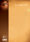
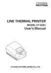
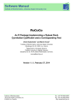
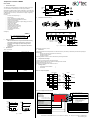
Temperature controller TRM500 User manual 1 TRM500 Functional description On-Off or PID control (see Fig. 1) Manual control 20 mm, 4 digit display, 2nd display optional Digital input filter with an adjustable time constant Custom 2-point linearization Digital input (remote start/stop or setpoint change) (see Annex D) Temperature range alarm Auxiliary alarm output Additional logic output (SSR) Configurable outputs (see Annex A) Autotuning function (see Annex C) Cold junction compensation Input calibration (see Annex E) 9 status LEDs OUT2 Relay 5 A 0000 The TRM500 is a versatile temperature controller with switching current up to 30 A. The device has a universal input for a wide range of resistance thermometers and thermocouples as well as a digital input. It is provided with a relay output, an alarm output, a DC logic output. The outputs can be configured for different tasks (see Annex A). The controller can be quickly configured by using three keys. Functions: – – – – – – – – – – – – – – 0000 Temperature sensor Alarm SENSOR Control Alarm Load OUT1 Relay 5/30 A DI Control on/off Setpoint SP1/SP2 switching Auto/Manual Pulse control OUT3 SSR Load Fig. 2. Block diagram 4 Installation and electrical wiring Fastenings Mounting hole Fig. 3. Mounting and dimensions Ordering key: POWER SUPPLY OUT1 – – N L1 230 VAC Make sure that the device is fully disconnected from auxiliary power before starting any commissioning or repair work. Connect the power supply only after the wiring has been completed. Do not use the device where it is subjected to flammable or explosive gas. – 3 LOAD Safety precautions Specifications 230 (96…264) V AC 5 VA Pt50, Pt100, Pt500, Pt1000, Ni100, Ni500, Ni1000 0,25% 2-, 3-, 4-wire 0,3 s 0,2 s 15 ohm internal B, J, K, L, N, R, S, T 0,50% 0,2 s 100 ohm potential free contact 70 ohm 1000 ohm Resistance thermometer Accuracy Connection circuit Sampling time for 3-wire Sampling time for 2- / 4-wire Lead resistance, max. Reference junction Thermocouple Accuracy Sampling time Lead resistance, max. Digital input ON, resistance max. OFF, resistance max. Relay outputs 5A / 250 VAC, 3A / 30 VDC (resistiv) optional 30A / 250 VAC, 20A / 30 VDC (resistiv) 5A / 250 VAC, 3A / 30 VDC (resistiv) 0/5 V, 25-40 mA 96 x 48 x 100 mm front IP54, rear IP20 -20 … +50 °C up to 80% (non-condensing) approx. 160 g OUT1 OUT2 Logic output OUT3 Dimensions IP Code Operating temperature Humidity Weight Parameter P50 P100 P500 P1E3 N100 N500 N1E3 tP.HA tP.J tP.L tP.N tP.t tP.S TP.R TP.B 5 A, 230 VAC 3 A, 30 VDC RTD 3-wire RTD 4-wire TC Maintenance Technical maintenance should be performed on the device at least every six months by maintenance personnel and comprising the following tasks: – Removing dust, dirt and foreign matter from the housing. – Checking mounting of device – Checking connections The safety guidelines in Section 2 must be observed when performing maintenance. 6 Transportation and storage The device must be transported in closed transport boxes. Protective measures against shocks, vibrations and humidity must be observed. Storage temperature range -30 to +60 °C. There may be no chemically active substances in the air. 7 Package content – – Temperature controller TRM500 User manual Measuring range, °C –100…+850 –100…+850 –100…+850 –100…+300 –60…+180 –60…+180 –60...+180 –100…+1300 –100…+1200 -100…+800 –100…+1300 –100…+400 0…+1750 0…+1750 +200…+1800 Output configuration DI SP t, s 0 t, s ON t, s 0 ON/OFF control t, s PID control OUT1 Relay 5/30 A Control OUT2 Relay 5 A Alarm DI DI OUT3 SSR Control Alarm OUT2 Relay 5 A Control OUT3 SSR OUT1 Relay 5/30 A Alarm Alarm logic OUT2 I ∩ (inside range) ON ConF=1.U or ConF=1.∩ OFF t OUT2 U (outside range) ON II OFF ConF=2.U or ConF=2. ∩ t OUT2 ON III OFF OUT1 ConF=3.U t ON OUT2 Relay 5 A OFF U.Lo U.Hi t Annex B. Displays and control elements Display D1 - measuring value (Operation) - setpoint (Operation) - control signal (Manual) - parameter group (Setup) - parameter name (Setup) - parameter value (Setup) — — — — error (sensor failure, CJC failure, exceedance of the measuring range) - setpoint (Operation) - measuring value (Manual) - control signal (Manual) - parameter name (Setup) - parameter value (Setup) T °C °C 1 1 Annex A. Output configuration Display D2 OFF N L1 N RTD 2-wire Fig. 4. Electrical wiring Table 2. Sensor types Relay L1 5/30 A, 230 VAC 3/20 A, 30 VDC SSR 0/5 VDC 25-40 mA 5 Power supply Power consumption, max. T SP+∆ SP SP - ∆ SENSOR The maximum wire size is 0,75 mm². Table 1. General data Sensor Pt50 Pt100 Pt500 Pt1000 Ni100 Ni500 Ni1000 K J L N T S R B DI OUT3 REMOTE 5A - relay 5 A, display with 20 mm digit height 30A - relay 30 A, display with 20 mm digit height +display with 10 mm digit height 2 OUT2 LOAD TRM500-X SP1 - lit when SP1 or SP1+SP2 is activ - flashes when correcting setpoint SP2 - lit when SP2 or SP1+SP2 is activ - flashes when correcting setpoint AUTO - lit when control is activ - flashes when PID autotuning TRM500 Shotly - increasing of parameter value - next parameter > 3 s - end of menu (oUt) TEMPERATURE TRANSMITTER TUP °C Shotly - decreasing of parameter value - previous parameter TNORM TDOWN SP1 AUTO ON SP2 MAN ALARM PROG PROG Shortly - selecting a menu item (Setup) - confirmation of the modification and switch to the next parameter (Setup) > 3 s - switch to the Setup mode (Operation) - cancel modification (Setup) TUP - lit when T > upper alarm limit TNORM - lit when T inside the alarm limits TDOWN - lit when T < lower alarm limit ON - lit when OUT1 or OUT3 is ON ALARM - lit when sensor failure and/or exceeding alarm limits MAN - lit when manual control is aktiv Fig. 1. Control akYtec GmbH · Vahrenwalder Str. 269 A · 30179 Hannover · Germany · Tel.: +49 (0) 511 16 59 672-0 · [email protected] Vers. 2015-08-14_003 Annex C. Configuration Operation PROG 284.9 285.0 Full setup Quick setup >3s T DOWN ON REG SET2 MAN ALARM oUt PROG PROG SET1 PROG FuLL FaST T UP T NORM Cont S.tYP T UP T NORM tuNE Sensor type [P100] (see Table 2) PROG PROG PROG PROG T UP T NORM T DOWN SET1 ON REG SET2 MAN ALARM FUnC new Setpoint SP1 0.0 HYST U.Lo T UP T NORM T DOWN SET1 ON REG SET2 MAN ALARM U.H 100.0 T UP T NORM T DOWN SET1 ON REG SET2 MAN ALARM new Setpoint SP2 PROG Control [on.oF] Pid = PID on.oF = ON/OFF Hysteresis [1.0] Range 0...1800 U.Lo Lower alarm limit [0.0] Range -250...+1800 S.tYP Sensor type [P100] U.H Upper alarm limit [100.0] Range -250...+1800 Cor.A Offset [0.0] Output mode [1.U] (see Annex A) 1.U = OUT1 - ON/OFF or PID OUT2 - ON if T > U.Hi or T < U.Lo OUT3 - OFF 1. = OUT1 - ON/OFF or PID OUT2 - ON if U.Lo < T < U.Hi OUT3 - OFF 2.U = OUT1 - OFF OUT2 - ON if T > U.Hi or T < U.Lo OUT3 - ON/OFF or PID 2. = OUT1 -OFF OUT2 - ON if U.Lo < T < U.Hi OUT3 - ON/OFF or PID 3.U = OUT1 - ON if T > U.Hi OUT2 - ON if T < U.Lo OUT3 - ON/OFF or PID Lower Alarm Limit [0.0] Range -250...+1800 Upper Alarm Limit [100.0] Range -250...+1800 Exit oFF = deactivated r-S = control on/off Set2 = switching SP1/SP2 Add2 = switching SP1/SP1+SP2 mAn1 = Manual mAn2 = Manual, using the last measured temperature insead of SP1 Filter time constant [0.01] Range 0...30 s F L.t bandwidth [10] F L.L Fiter Range 0...100 °C circuit [3] r.Con RTD 2 = 2-wire 3 = 3-wire 4 = 4-wire see Annex E „Calibration“ rUn tuNE oUt T UP T NORM T DOWN SET1 ON REG SET2 MAN ALARM tuNE Manual control Initial control signal [Last] Range 0.00...100 Last = last value befor switching to Manual 285.4 tuNE T UP T NORM SET2 MAN ALARM Cancel PROG SET1 ON REG SET2 MAN ALARM Manual control - Indication [P] P = Control signal t-P = Temperature/Control signal P. nd 285.4 Exit PROG tuNE T DOWN SET1 ON REG SET2 MAN ALARM c Minimum puls length [0.050] Range 0...9.999 s Good tuNE T UP T NORM PROG T DOWN SET1 ON REG SET2 MAN ALARM Autotuning successfully completed T UP T NORM se displayed if FUnC = on.oF REG T DOWN FA L tuNE T UP T NORM PROG T DOWN SET1 ON REG SET2 MAN ALARM Autotuning cannot be successfully completed FUnC Control OUT1/OUT3 [on.oF] displayed if FUnC = Pid T DOWN ON Autotuning P. n 5 dL PROG T UP T NORM SET1 PROG Exit PROG period [1.0] Prd PWM Range 0...60 s PROG Exit (see Annex D) Range -99.9...+9.99 ConF oUt PROG nP.F Digital input mode [oFF] (see Table 2) Exit Corr c ALARM displayed if FUnC = on.oF displayed if inP.F = Set2 or inP.F = Add2 D. nP se REG MAN PROG SP2 SEnS Calibration 5 ON SET2 150.0 SP2 Autotuning displayed if inP.F = mAn1 or mAn2 SET1 PROG SP1 Digital input T DOWN displayed if tP.L = RTD SP1 Sensor Control Setpoint SP1 adjustment 285.0 Note: The values in the square brackets are factory settings Exit Pid = PID on.oF = ON/OFF HYST Hysteresis [1.0] Switch to factory settings Range 0...1800 P d.P P-component [10.00] Range 0.001...9999 P d. I-component [50.0] Range 0...999.9 Press and PROG simultaneously, then PROG for confirmation Disable cold junction compensation (CJC) [25.0] P d.d D-component Range 0...999.9 Press PROG and , simultaneously, then PROG for confirmation Exit PROG Annex D. Digital input configuration (Parameter InP.F) 1. Setpoint switching 1a. Switching SP1/SP2 SP2 SP1 Measured value 284.9 SP1 DI 2a. Manual control, indication „Temperature/Control signal“ inP.F = Set2 SP1 = 285 SP2 = 40 285.0 T UP Measured value T NORM T DOWN SET1 ON REG SET2 MAN ALARM Measured value InP.F = Set2 - switching SP1/SP2 or InP.F = Add2 - switching SP1/SP1+SP2 40.0 Measured value 285.0 SP1 SET1 ON REG SET2 MAN ALARM DI DI Measured value InP.F = mAn1 - switching to Manual, when switched back - control with the last setpoint InP.F = mAn2 - switching to Manual, when switched back - control with the last measured temperature instead of setpoint 285.0 0.0 Control signal T DOWN ON REG SET2 MAN ALARM Measured value SP1 325.0 Control signal T UP T NORM T DOWN SET1 ON REG SET2 MAN ALARM 43.1 284.9 Measured value 285.0 T UP T NORM T DOWN SET1 ON REG SET2 MAN ALARM SET1 ON REG Measured value SET2 MAN ALARM Control signal T UP T NORM T DOWN SET1 ON REG SET2 MAN ALARM Measured value 284.9 T UP T NORM T DOWN 100.0 284.9 T UP T NORM T DOWN SET1 ON REG SET2 MAN ALARM 43.1 Measured value T UP T NORM T DOWN SET1 ON REG SET2 MAN ALARM Setpoint 350.9 285.0 T UP T NORM T DOWN SET1 ON REG SET2 MAN ALARM DI T DOWN SET1 ON REG SET2 MAN ALARM Measured value 206.2 285.0 Setpoint T UP T UP T NORM T DOWN SET1 ON REG SET2 MAN ALARM if inP.F = mAn2 then Setpoint = last measured value T NORM T DOWN SET1 ON REG SET2 MAN ALARM DI DI Measured value DI 284.9 285.0 SP1 InP.F = r-S - control on/off T UP T NORM T DOWN SET1 ON REG SET2 MAN ALARM back to menu „Calibration“ Annex E. Calibration Password 17 PASS Corr T UP T NORM T DOWN SET1 ON REG SET2 MAN ALARM Calibration factor Y1=0 flashing Y1 17 Corr У1 T UP T NORM T DOWN SET1 ON REG SET2 MAN ALARM PROG Corr ON REG SET2 MAN ALARM Corr T UP T NORM T DOWN SET1 ON REG SET2 MAN ALARM oUt Corr T UP T NORM PROG T DOWN SET1 ON REG SET2 MAN ALARM To calibrate the first point: connect a resistance decade (for RTD) or mV-signal (for TC) as a reference signal to the input „Sensor“ 5.3 У1 NULL T UP T DOWN SET1 PROG Measured value according to the reference signal PROG T NORM 5.0 T UP T NORM T DOWN SET1 ON REG SET2 MAN ALARM PROG У1 T UP T NORM T DOWN SET1 ON REG SET2 MAN ALARM Adjust temperature according to the reference table save calibration factor Y1 PROG Y2 PROG Corr T UP T NORM T DOWN SET1 ON REG SET2 MAN ALARM APLY Corr oUt T UP T NORM T DOWN SET1 ON REG SET2 MAN ALARM Corr T UP PROG T NORM don't save calibration factor Y1 T DOWN SET1 ON REG SET2 MAN ALARM flashing value 2nd point calibration when required save calibration factor Y2 PROG Y3 Corr T UP T NORM T DOWN SET1 ON REG SET2 MAN ALARM APLY Corr oUt T UP T NORM T DOWN SET1 ON REG SET2 MAN ALARM Corr T UP T NORM PROG don't save calibration factor Y2 T DOWN SET1 ON REG SET2 MAN ALARM PROG 3rd point calibration when required APLY Corr PROG T UP T NORM T DOWN SET1 ON REG SET2 MAN ALARM oUt Corr T UP T NORM PROG don't save calibration factor Y3 T DOWN SET1 ON REG SET2 MAN ALARM Control signal manipulation DI 206.2 Control signal 0.0 T UP T NORM 284.9 SP1+SP2 Setpoint 5s inP.F = Add2 SP1 = 285 SP2 = 40 DI 3. Control on/off ALARM T UP 284.9 SP1 REG MAN Control signal manipulation T NORM SET1 1b. Switching SP1/SP1+SP2 ON SET2 284.9 Control signal Measured value Control signal manipulation SET1 284.9 DI Measured value T DOWN 284.9 SP1 Measured value T UP T DOWN T UP T NORM DI 2. Switching to Manual 285.0 inP.F = mAn1 P.ini = 0.0 P.ind = P T NORM DI 284.9 SP2 284.9 Setpoint DI DI 2b. Manual control, indication „Control signal“ inP.F = mAn1 P.ini = 0.0 P.ind = t-P save calibration factor Y3 if inP.F = mAn2 then Setpoint = last measured value