1
C440GX+ Server Board
Product Guide
Order Number: 728967-001
Disclaimer
Intel Corporation (Intel) makes no warranty of any kind with regard to this material, including, but not limited
to, the implied warranties of merchantability and fitness for a particular purpose. Intel assumes no
responsibility for any errors that may appear in this document. Intel makes no commitment to update nor to
keep current the information contained in this document. No part of this document may be copied or
reproduced in any form or by any means without prior written consent of Intel.
An Intel product, when used in accordance with its associated documentation, is "Year 2000 Capable" when,
upon installation, it accurately stores, displays, processes, provides, and/or receives date data from, into, and
between the twentieth and twenty-first centuries, including leap year calculations, provided that all other
technology used in combination with said product properly exchanges date data with it.
† Third party brands and trademarks are the property of their respective owners.
Copyright 1998, 1999 Intel Corporation.
Contents
1 Description
Server Board Features ......................................................................................................... 9
Back Panel Connectors ............................................................................................. 10
Server Board Connector and Component Locations.................................................. 11
Processor .................................................................................................................. 12
Memory .................................................................................................................... 13
440GX Host Bridge / Memory Controller ............................................................................ 13
Peripherals ......................................................................................................................... 14
Super I/O Chip........................................................................................................... 14
Add-in Board Slots ............................................................................................................. 14
Video .................................................................................................................................. 15
SCSI Controller .................................................................................................................. 16
IDE Controller..................................................................................................................... 16
Network Controller.............................................................................................................. 17
Keyboard and Mouse ......................................................................................................... 17
ACPI .................................................................................................................................. 18
Server Management........................................................................................................... 19
Baseboard Management Controller (BMC) ................................................................ 19
Emergency Management Port Console ..................................................................... 20
Security .............................................................................................................................. 20
Security with Mechanical Locks and Monitoring......................................................... 20
Software Locks .......................................................................................................... 20
2 Upgrading
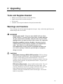
Tools and Supplies Needed................................................................................................ 25
Warnings and Cautions ...................................................................................................... 25
Server Board ...................................................................................................................... 26
Installing the Server Board......................................................................................... 26
Removing the Server Board....................................................................................... 30
Voltage Regulator Modules (VRMs) ................................................................................... 31
Processors ......................................................................................................................... 32
Installing a Processor ................................................................................................ 32
Removing a Processor .............................................................................................. 36
Memory .............................................................................................................................. 37
Installing DIMMs ........................................................................................................ 37
Removing DIMMs ...................................................................................................... 38
Replacing the Back up Battery ........................................................................................... 39
iii
3 Configuration Software and Utilities
Hot Keys............................................................................................................................. 41
Power On Self Test (POST) ............................................................................................... 42
Using BIOS Setup .............................................................................................................. 43
Record Your Setup Settings ...................................................................................... 43
If You Cannot Access Setup ...................................................................................... 43
Starting Setup............................................................................................................ 44
Setup Menus ............................................................................................................. 44
Main Menu................................................................................................................. 45
Advanced Menu......................................................................................................... 48
Security Menu............................................................................................................ 51
Server Menu .............................................................................................................. 52
Boot Menu ................................................................................................................. 54
Exit Menu................................................................................................................... 56
Using the System Setup Utility ........................................................................................... 57
When to Run the System Setup Utility ....................................................................... 57
What You Need to Do................................................................................................ 58
Running the SSU ....................................................................................................... 58
Customizing the SSU................................................................................................. 61
Launching a Task ...................................................................................................... 61
Resource Configuration Add-in (RCA) Window.......................................................... 62
Multiboot Options Add-in............................................................................................ 63
Security Add-in .......................................................................................................... 64
SEL Manager Add-in ................................................................................................. 65
FRU Manager Add-in................................................................................................. 66
SDR Manager Add-in................................................................................................. 67
Exiting the SSU.......................................................................................................... 67
Emergency Management Port Console .............................................................................. 68
How EMP Console Works.......................................................................................... 69
Requirements ............................................................................................................ 71
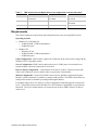
Setting up the Server for the EMP ............................................................................. 72
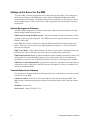
Main EMP Console Window ...................................................................................... 73
Server Control Operations ......................................................................................... 74
Phonebook ................................................................................................................ 77
Management Plug-ins................................................................................................ 78
FRUSDR Load Utility.......................................................................................................... 81
When to Run the FRUSDR Load Utility...................................................................... 81
What You Need to Do................................................................................................ 81
How You Use the FRUSDR Load Utility..................................................................... 82
Upgrading the BIOS ........................................................................................................... 85
Preparing for the Upgrade ......................................................................................... 85
Upgrading the BIOS................................................................................................... 86
Recovering the BIOS ................................................................................................. 87
Changing the BIOS Language ................................................................................... 87
iv
Contents
Using the Firmware Update Utility ...................................................................................... 88
Running the Firmware Update Utility ......................................................................... 88
Installing Video Drivers....................................................................................................... 88
Using the Adaptec SCSI Utility ........................................................................................... 89
Running the SCSI Utility ............................................................................................ 89
4 Solving Problems
Resetting the System ......................................................................................................... 91
Fault Resilient Booting........................................................................................................ 91
Initial System Startup ......................................................................................................... 91
Checklist .................................................................................................................... 92
Running New Application Software..................................................................................... 92
Checklist .................................................................................................................... 92
After the System Has Been Running Correctly ................................................................... 93
Checklist .................................................................................................................... 93
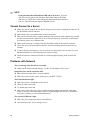
More Problem Solving Procedures ..................................................................................... 94
Preparing the System for Diagnostic Testing ............................................................. 94
Monitoring POST ....................................................................................................... 94
Verifying Proper Operation of Key System Lights ...................................................... 94
Confirming Loading of the Operating System ............................................................ 94
Specific Problems and Corrective Actions .......................................................................... 95
Power Light Does Not Light ....................................................................................... 95
No Characters Appear on Screen .............................................................................. 95
Characters Are Distorted or Incorrect ........................................................................ 96
System Cooling Fans Do Not Rotate Properly ........................................................... 96
Diskette Drive Activity Light Does Not Light ............................................................... 97
Hard Disk Drive Activity Light Does Not Light ............................................................ 97
CD-ROM Drive Activity Light Does Not Light ............................................................. 97
Cannot Connect to a Server ...................................................................................... 98
Problems with Network .............................................................................................. 98
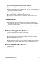
PCI Installation Tips................................................................................................... 99
Problems with Application Software.................................................................................... 99
Bootable CD-ROM Is Not Detected .................................................................................... 99
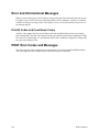
Error and Informational Messages.................................................................................... 100
Port-80 Codes and Countdown Codes..................................................................... 100
POST Error Codes and Messages ................................................................................... 100
5 Technical Reference
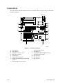
Connectors....................................................................................................................... 102
ATX Style Front Panel Connector ............................................................................ 103
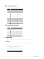
Main Power Connector ............................................................................................ 104
ATX Aux Power Connector ...................................................................................... 104
Fan Interface ........................................................................................................... 104
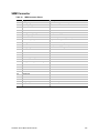
SMM Connector....................................................................................................... 105
Front Panel Connector, 30 pin ................................................................................. 106
C440GX+ Server Board Product Guide
v
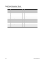
Server Board Jumpers ..................................................................................................... 107
General Procedure to Change Jumper Setting ........................................................ 108
Recovery Boot Jumper ............................................................................................ 109
Boot Block Write Protect Jumper ............................................................................. 109
6 Regulatory and Integration Information
Regulatory Compliance .................................................................................................... 111
Installation Instructions ..................................................................................................... 112
Ensure EMC ............................................................................................................ 112
Ensure Host Computer and Accessory Module Certifications .................................. 113
Prevent Power Supply Overload .............................................................................. 113
Place Battery Marking on Computer ........................................................................ 114
Use Only for Intended Applications.......................................................................... 114
Installation Precautions .................................................................................................... 114
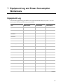
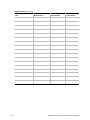
7 Equipment Log and Power Consumption Worksheets
Equipment Log ................................................................................................................. 115
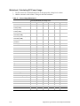
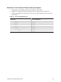
Current Usage ......................................................................................................... 117
Calculating Power Consumption .............................................................................. 117
Index
Figures
1.
2.
3.
4.
5.
6.
7.
8.
9.
10.
11.
12.
13.
14.
15.
16.
17.
18.
19.
20.
21.
22.
23.
vi
Back Panel Connectors ............................................................................................. 10
Server Board Connector and Component Locations......................................................... 11
Server Board Screw Hole Locations .......................................................................... 27
nstall Fans ................................................................................................................. 27
Mounting Retention Mechansim ................................................................................ 28
Install Fans ................................................................................................................ 29
Installing a VRM ........................................................................................................ 31
Attach Retention Mechansim to Processor ................................................................ 33
Install Processor ........................................................................................................ 34
Attaching the Retention Mechansim to the Termination Card .................................... 35
Install the Termination Card....................................................................................... 36
Installing DIMMs ........................................................................................................ 37
Replacing the Lithium Battery .................................................................................... 40
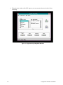
System Setup Utility Main Window ............................................................................ 60
EMP Console in Command State .............................................................................. 69
EMP Console in Redirect State ................................................................................. 70
Connect Dialog .......................................................................................................... 75
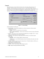
Power On/Off Dialog.................................................................................................. 76
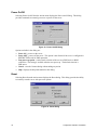
Reset Dialog .............................................................................................................. 76
Phonebook Dialog ..................................................................................................... 77
Connector Locations................................................................................................ 102
ATX Style Front Panel Connector ............................................................................ 103
Jumper Locations .................................................................................................... 107
Contents
Tables
1.
2.
3.
4.
5.
6.
7.
8.
9.
10.
11.
12.
13.
14.
15.
16.
17.
18.
Server Board Features ................................................................................................ 9
NIC LEDs .................................................................................................................................. 10
Software Security Features ....................................................................................... 22
Configuration Utilities................................................................................................. 41
Hot Keys.................................................................................................................... 41
EMP Console Access Modes (Server configured for console redirection) ................. 70
EMP Console Access Modes (Server not configured for console redirection)............ 71
ATX Style Front Panel Connector Pinout ................................................................. 103
Main Power Connector Pinout ................................................................................. 104
ATX Aux Power Connector Pinout ........................................................................... 104
Fan Connector Pinout.............................................................................................. 104
SMM Connector Pinout............................................................................................ 105
Front Panel Connector Pinout.................................................................................. 106
Server Board Jumper Summary .............................................................................. 107
Safety Regulations ................................................................................................................111
EMC Regulations...................................................................................................................111
Power Usage Worksheet 1 ...................................................................................... 118
Power Usage Worksheet 2 ...................................................................................... 119
C440GX+ Server Board Product Guide
vii
viii
Contents
1 Description
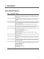
Server Board Features
Table 1.
Server Board Features
Feature
Description
Processors
Up to two Intel® Pentium® II Xeon™ or Pentium III Xeon processors. The server
board has one emmbedded voltage regulator and two VRM slots to provide the
required voltage.
Memory (DRAM)
Four 72 bit sockets for 168-pin, gold contact, 100 MHz, PC/100 compliant, ECC
or non-ECC, registered or unbuffered, SDRAM dual inline memory modules
(DIMM).
Video Memory
Installed: 2 MB of video memory.
PCI bus
Four standard PCI (PCI-33/32 bit) expansion slots for add-in boards. 1x32 bit
PCI bus. Embedded devices: video controller, Network Interface Controller
(NIC), and SCSI controller.
Two PCI-66/32 bit 5V expansion slots (backwards compatible to PCI-33/32).
ISA bus
One ISA expansion slot for an add-in board. Embedded PC-compatible support
(serial, parallel, mouse, keyboard, diskette, and Plug and Play features).
Server Management
Thermal/voltage monitoring and error handling.
Real time clock/calendar (RTC).
Front panel controls and indicators (LEDs).
System Setup Utility (SSU).
Basic Input/Output System (BIOS), Power On Self Test (POST), and Setup
stored in flash memory.
Graphics
Integrated onboard Cirrus Logic† CL-GD5480 super video graphics array
(SVGA) controller.
SCSI
Adaptec† AIC-7896, supporting onboard Ultra2 (LVDS) Wide and Ultra-wide
SCSI interfaces. Support for the Adaptec ARO-1130 RAIDPort† card is built into
PCI slot 4.
Network
Integrated onboard NIC, an Intel® 82559 single chip PCI LAN controller for 10 or
100 Mbps TX Fast Ethernet networks. RJ-45 Ethernet connector and indicator
LEDs at I/O back panel.
System I/O
PS/2†-compatible keyboard and mouse ports, 6 pin DIN.
Advanced parallel port, supporting Enhanced Parallel Port (EPP) level 1.7 and
1.9, ECP, compatible 25 pin.
VGA video port, 15 pin.
Two serial ports, 9 pin.
Network: RJ-45 Ethernet port.
Two USB ports.
Form Factor
Server ATX form factor, 12 × 13 inches, ATX 2.01 compliant I/O.
9
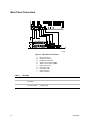
Back Panel Connectors
C
A
B
D
F G
E
H
I
J
OM08498
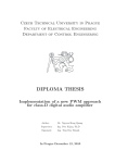
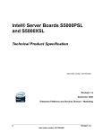
Figure 1. Back Panel Connectors
A.
B.
C.
D.
E.
F.
G.
H.
I.
J.
Table 2.
10
Mouse connector
Keyboard connector
Parallel Port connector
Serial Port connector (COM1)
Serial Port connector (COM2)
Network connector
Green NIC LED
Orange NIC LED
USB connectors
Video connector
NIC LEDs
NIC LED Color
If it’s on
If it’s blinking
If it’s off
Orange
100 Mbps network
connection.
NA
10 Mbps network connection.
Green
Linked to network,
no network traffic.
Linked to network, sending or
receiving data.
Not linked to network.
Description
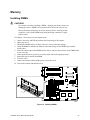
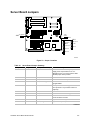
Server Board Connector and Component Locations
A B C
E F GH I
D
J
JJ
II
HH
K
GG
FF
EE
DD
CC
L
M
N
O
PRI
SEC
P
Q
BB
AA
R
Z
Y
S
X
W
V
U T
OM08499
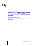
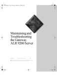
Figure 2. Server Board Connector and Component Locations
A.
B.
C.
D.
E.
F.
G.
H.
I.
J.
K.
L.
M.
N.
O.
P.
Q.
Primary processor
Secondary processor
PROC FAN2 TOP fan connector
DIMM slots
ATX aux power connector
L2 cache VRM connector
P2 secondary VRM connector
Fan connector FAN3
Fan connector FAN4
Front panel connector, 30 pin
Main power connector
Fan connector FAN2
ATX front panel connector
Floppy connector
IDE connectors
Battery
Isolated Server Management
(ISOL) IMB connector
R. Jumper blocks
C440GX+ Server Board Product Guide
S.
T.
U.
Fan connector FAN1
Ultra wide SCSI connector
Server Monitor Module (SMM)
connector
V. External Wake on LAN† connector
W. Ultra2/LVD SCSI connector
X. Hard drive LED connector
Y. Chassis intrusion connector
Z. PCI connectors
AA. PCI-66 connectors
BB. Fan connector FAN2B
CC. PROC FAN1 BTM fan connector
DD. Video connector
EE. USB connectors
FF. NIC connector
GG. Serial port connector (COM2)
HH. Parallel port connector
II. Serial port connector (COM1)
JJ. Mouse/keyboard connectors
11
Processor
Each Intel Pentium II Xeon or Pentium III Xeon processor is packaged in a cartridge that includes
the processor core with an integrated 32 KB primary (L1) cache and the secondary (L2) cache.
The processor implements the MMX™ technology and maintains full backward compatibility with
the 8086, 80286, Intel386™, Intel486™, Pentium, Pentium Pro and previous Pentium II processors.
The processor’s numeric coprocessor significantly increases the speed of floating point operations
and complies with ANSI/IEEE standard 754-1985.
Each processor cartridge connects to the server board through a 330 pin edge connector. The
cartridge is secured by a retention mechanism attached to the server board. Depending on
configuration, your server may have one or two processors.
The processor external interface is MP (Multi-Processor) ready and operates at 100 MHz. The
processor contains a local APIC (Advanced Programmable Interrupt Controller) section for
interrupt handling in MP and UP (Uni-Processor) environments.
The second level cache is located on the substrate of the S.E.C. cartridge. The cache includes burst
pipelined synchronous static RAM (BSRAM). The L2 cache is offered in 512 KB, 1 MB, and
2 MB configurations, with error correcting code (ECC) that operates at half the core clock rate.
Voltage Regulator Modules (VRMs)
One integrated VRM and two VRM sockets provide power to the processors. The two socketed
VRMs derive power from the 5V or 12V supply depending the the type of VRM used. The
integrated VRM power the primary processor. The VRM socket labeled "Primary VRM" powers
the L2 cache for both porcessors and must be populated. The VRM socket labeled "Secondary
VRM" powers the secondary processor and must be populated if a processor is installed in the
secondary processor slot.
If you are integrating your C440GX+ server board with an Intel® Cabrillo-C chassis, use the
provided VRMs. See this URL for information on which URM to use:
http://www.intel.com/go/serverbuilder/
Look under Reference Chassis.
12
Description
Memory
Only 100 MHz PC/100 ECC or Non-ECC SDRAM is supported by the server board. Memory is
partitioned as four banks of SDRAM DIMMs, each providing 72 bits of noninterleaved memory
(64 bit main memory plus ECC):
•
•
Install from 64 MB to 2 GB of memory, using registered DIMMs.
Install from 32 MB to 1 GB of memory, using unbuffered DIMMs.
Memory should be added in order from slot 1 to slot 4.
✏
NOTE
Do not mix registered and unbuffered memory. Non ECC memory may be
installed but ECC memory is recommended in a server environment.
Mixing Non-ECC memory and ECC memory causes all ECC features to be
disabled.
The controller automatically detects, sizes, and initializes the memory array, depending on the
type, size, and speed of the installed DIMMs, and reports memory size and allocation to the server
via configuration registers.
✏
NOTE
Use DIMMs that have been tested for compatibility with the server board.
Contact your sales representative or dealer for a current list of approved
memory modules. Check the Intel Customer Support website for the latest
tested memory list:
http://support.intel.com/support/motherboards/server/C440gx/compat.htm
440GX Host Bridge / Memory Controller
The C440GX+ is designed around the Intel® 82440GX AGPSet (440GX). This device provides
100MHz processor host bus interface support, DRAM controller, PCI bus interface, AGP interface
(used on C440GX+ for PCI-66/5V), and power management functions. The host bus/memory
interface in the 440GX is optimized for 100MHz operation, using 100MHz SDRAM main
memory. The PCI interface is PCI 2.1-compliant, providing a 33 MHz / 5V signaling environment
for embedded controllers and slots in the single PCI segment on C440GX+. The 440GX memory
controller supports up to 2 GB of ECC or Non-ECC memory, using PC/100 compliant
Synchronous DRAM (SDRAM) devices on DIMM plug-in modules. ECC can detect and correct
single-bit errors, and detect multiple-bit errors.
C440GX+ Server Board Product Guide
13
Peripherals
Super I/O Chip
The National† 87309 device supports two serial ports, one parallel port, diskette drive,
PS/2-compatible keyboard and mouse. The server board provides a connector interface for each
port.
Serial Ports
Each serial port can be set to one of four different COMx ports and can be enabled separately.
When enabled, each port can be programmed to generate edge or level sensitive interrupts. When
disabled, serial port interrupts are available to add-in boards.
Parallel Port
The 87309 provides one IEEE 1284-compatible 25 pin bidirectional EPP (supporting levels 1.7
and 1.9). BIOS programming of the 87309 registers enable the parallel port and determine the port
address and interrupt. ECP mode is supported with 2 possible DMA channels. When disabled, the
interrupt is available to add-in boards.
Add-in Board Slots
The server board has one full length ISA bus connector. ISA features:
•
•
•
•
•
•
Bus speed up to 8.33 MHz
16 bit memory addressing
Type A transfers at 5.33 Mbps
Type B transfers at 8 Mbps
8 or 16 bit data transfers
Plug and Play ready
The server board has four full length standard PCI (PCI-33/32 bit)connectors. PCI features:
•
•
•
•
•
•
•
14
Bus speed up to 33 MHz
32 bit memory addressing
5 V signaling environment
Burst transfers of up to 133 Mbps
8, 16, or 32 bit data transfers
Plug and Play ready
Parity enabled
Description
The server board has two full length PCI-66 universal connectors (5 volt/3.3 volt cards designed
for the 3.3v connector -cards with only one notch- will not fit). PCI features:
•
•
•
•
•
•
•
✏
Bus speed up to 66 MHz
32 bit memory addressing
5 V/3.3 V signaling environment
Burst transfers of up to 266 Mbps
8, 16, or 32 bit data transfers
Plug and Play ready
Parity enabled
NOTE
If you install a PCI-33 card into one of the PCI-66 slots, the bus speed for
both slots will be lowered to 33 MHz.
The components on some full length cards installed in slot 6 may interfere
with the DIMM connector latches.
Video
The onboard, integrated Cirrus Logic CL-GD5480 64 bit VGA chip contains an SVGA controller
that is fully compatible with these video standards: CGA, EGA, Hercules† Graphics, MDA, and
VGA. The standard configuration comes with 2 MB of 10 ns onboard Synchronous Graphics
Memory (SGRAM). The video controller supports pixel resolutions of up to 1600 x 1200 and up
to 16.7 Million colors.
The SVGA controller supports analog VGA monitors (single and multiple frequency, interlaced
and noninterlaced) with a maximum vertical retrace noninterlaced frequency of 100 Hz.
You cannot add video memory to the server board. Depending on the environment, the controller
displays up to 16.7 M colors in some video resolutions. It also provides hardware accelerated bit
block transfers (BITBLT) of data.
C440GX+ Server Board Product Guide
15
SCSI Controller
The embedded Adaptec AIC-7896 dual function SCSI controller provides both Ultra2 (LVDS)
wide and Ultra wide SCSI interfaces as two independent PCI functions. PCI slot 4 is
RAID-upgradeable, providing additional support for the ARO1130 RAIDPort controller by
Adaptec.
No logic, termination, or resistor loads are required to connect devices to the SCSI controller other
than termination in the device at the end of the cable. The SCSI bus is terminated on the server
board with active terminators that cannot be disabled. The onboard device must always be at one
end of the bus.
IDE Controller
IDE is a 16 bit interface for intelligent disk drives with disk controller electronics onboard. The
PCI/ISA/IDE Accelerator, also known as PIIX4e, is a multifunction device on the server board that
acts as a PCI based Fast IDE controller. The device controls:
•
•
•
•
•
•
✏
PIO and IDE DMA/bus master operations
Mode 4 timings
Transfer rates up to 33 MB/s
Buffering for PCI/IDE burst transfers
Master/slave IDE mode
Up to two devices per channel; two channels, IDE0 and IDE1
NOTE
18 inch maximum length of IDE cable on each channel: You can connect
an IDE signal cable, up to a maximum of 18 inches each, to each
IDE connector on the server board. Each cable can support two devices, one
at the end of the cable and one 6 inches from the end of the cable.
16
Description
Network Controller
The server board includes a 10BASE-T/100BASE-TX network solution based on the Intel 82559
single chip Fast Ethernet PCI Bus Controller. As a PCI bus master, the controller can burst data at
up to 132 MB/s. The controller contains two receive and transmit FIFO buffers that prevent data
overruns or underruns while waiting for access to the PCI bus. The controller has the following:
•
•
•
•
•
•
•
32 bit PCI bus master interface (direct drive of bus), compatible with PCI Bus Specification,
Revision 2.1
Chained memory structure with improved dynamic transmit chaining for enhanced
performance
Programmable transmit threshold for improved bus utilization
Early receive interrupt for concurrent processing of receive data
Onchip counters for network management
Autodetect and autoswitching for 10 or 100 Mbps network speeds
Support for both 10 Mbps and 100 Mbps networks, capable of full or half duplex, with
back-to-back transmit at 100 Mbps
The network status LEDs on the server board indicate:
•
•
•
Transmit/receive activity on the LAN
Valid link to the LAN
10/100 Mbps transfer mode
Keyboard and Mouse
The keyboard/mouse controller is PS/2-compatible. The server may be locked automatically if
there is no keyboard or mouse activity for a predefined length of time, if specified through the
System Setup Utility (SSU). Once the inactivity (lockout) timer has expired, the keyboard and
mouse do not respond until the previously stored password is entered.
C440GX+ Server Board Product Guide
17
ACPI
The C440GX+ supports the Advanced Configuration and Power Interface (ACPI) as defined by the
ACPI 1.0 and PC97 specifications. An ACPI aware operating system can put the system into a
state where the hard drives spin down, the system fans stop, and all processing is halted. However,
the power supply will still be on and the processors will still be dissipating some power, so the
power supply fan and processor fans will still run.
The C440GX+ supports sleep states s0, s4, and s5. With future versions of Microsoft Windows†
9X that support ACPI, the BIOS will only support sleep states s0 and s5. With future versions of
Microsoft Windows NT†x that support ACPI, the BIOS will support sleep states s0, s4, and s5.
•
•
•
s0: Normal running state.
s4: Hibernate or Save to Disk: The memory and machine state are saved to disk. Pressing the
power button or other wakeup event will restore the system state from the disk and resume
normal operation. This assumes that no hardware changes have been made to the system while
it was off.
s5: Soft off: Only the RTC section of the PIIX4 and the BMC are running in this state.
CAUTION
The system is off only when the AC power is disconnected.
18
Description
Server Management
Server Management features are implemented using one microcontroller.
Baseboard Management Controller (BMC)
All server management functionality is concentrated in the BMC. The BMC and associated
circuitry are powered from + 5V_Standby, which remains active when server power is switched
off and the server is still plugged into AC power.
One major function of the BMC is to autonomously monitor system management events, and log
their occurrence in the nonvolatile System Event Log (SEL). These include events such as
overtemperature and overvoltage conditions, fan failure, or chassis intrusion. To enable accurate
monitoring, the BMC maintains the nonvolatile Sensor Data Record (SDR), from which sensor
information can be retrieved. The BMC provides an ISA host interface to SDR sensor
information, so software running on the server can poll and retrieve the server’s current status.
SEL contents can be retrieved after system failure, for analysis by field service personnel using
server management software tools such as Intel Server Control available on the CD-ROM that
ships with the C440GX+ server board or from the Intel Customer Support website:
http//suport.intel.com/support/motherboards/server/C440gx
Because the BMC is powered by 5V_Standby, SEL and SDR information are also available via the
IMB (Intelligent Management Bus). An Emergency Management Card, such as the
Intel® LANDesk® SMM (Server Monitor Module) card available with the LANDesk Server
Manager Pro package, can obtain the SEL and make it remotely accessible using a LAN or
telephone line connection. While it receives the proper current, the BMC does the following:
•
•
•
•
•
•
•
•
•
•
•
•
•
•
•
Monitors server board temperature and voltage
Monitors processor presence and controls FRB
Detects and indicates baseboard fan failure
Manages the SEL interface
Manages the SDR Repository interface
Monitors the SDR/SEL timestamp clock
Manages the server board Field Replaceable Unit (FRU) information interface
Monitors the system management watchdog timer
Monitors the periodic SMI timer
Manages front panel NMI handling
Monitors the event receiver
Manages the ISA host and IMB interface
Controls secure mode, including video blanking, floppy write-protect monitoring, and front
panel lock/unlock initiation
Manages the sensor event initialization agent
Controls Wake on LAN via Magic Packet† support
C440GX+ Server Board Product Guide
19
Emergency Management Port Console
The Emergency Management Port (EMP) Console provides an interface to the Emergency
Management Port (EMP). This interface allows remote server management via a modem or direct
(serial port to serial port) connection.
The server control operations available with EMP Console are:
•
•
•
Connecting to remote servers
Powering the server on or off
Resetting the server
The EMP Console uses three management plug-ins to monitor the server:
•
•
•
SEL Viewer
SDR Viewer
FRU Viewer
The EMP Console also has Phonebook plug-in that can be used to create and maintain a list of
servers and their phone numbers.
Security
To help prevent unauthorized entry or use of the server, Intel® Server Control server management
software monitors the system intrusion switch.
Security with Mechanical Locks and Monitoring
If installed, you can activate the chassis intrusion alarm switch. When the side door is opened, the
switch transmits an alarm signal to the server board, where BMC firmware and server management
software process the signal. The system can be programmed to respond to an intrusion by
powering down or by locking the keyboard, for example.
Software Locks
The BIOS Setup and the System Setup Utility (SSU) provide a number of security features to
prevent unauthorized or accidental access to the system. Once the security measures are enabled,
you can access the system only after you enter the correct password(s). For example:
•
•
•
•
•
•
•
20
Enable the keyboard lockout timer so that the server requires a password to reactivate the
keyboard and mouse after a specified time out period1 to 120 minutes.
Set and enable an administrative password.
Set and enable a user password.
Set secure mode to prevent keyboard or mouse input and to prevent use of the front panel reset
and power switches.
Activate a hot key combination to enter secure mode quickly.
Disable writing to the diskette drive when secure mode is set.
Disable access to the boot sector of the operating system hard disk drive.
Description
Using Passwords
You can set either the user password, the administrator password, or both passwords. If only the
user password is set, you:
•
•
•
Must enter the user password to enter BIOS Setup or the SSU.
Must enter the user password to boot the server if Password on Boot is enabled in either the
BIOS Setup or SSU.
Must enter the user password to exit secure mode.
If only the administrator password is set, you:
•
•
•
Must enter the administrator password to enter BIOS Setup or the SSU.
Must enter the administrator password to boot the server if Password on Boot is enabled in
either the BIOS Setup or SSU.
Must enter the administrator password to exit secure mode.
If both passwords are set, you:
•
•
•
•
May enter the user password to enter BIOS Setup or the SSU. However, you will not be able
to change many of the options.
Must enter the administrator password if you want to enter BIOS Setup or the SSU and have
access to all of the options.
May enter either password to boot the server if Password on Boot is enabled in either the BIOS
Setup or SSU.
May enter either password to exit secure mode.
Secure Mode
Configure and enable the secure boot mode by using the SSU. When secure mode is in effect:
•
•
You can boot the server and the operating system will run, but you must enter the user
password to use the keyboard or mouse.
You cannot turn off system power or reset the server from the front panel switches.
Secure mode has no effect on functions enabled via the Server Manager Module or power control
via the real time clock.
Taking the server out of secure mode does not change the state of system power. That is, if you
press and release the power switch while secure mode is in effect, the system will not be powered
off when secure mode is later removed. However, if the front panel power switch remains
depressed when secure mode is removed, the server will be powered off.
C440GX+ Server Board Product Guide
21
Summary of Software Security Features
The table below lists the software security features and describes what protection each offers. In
general, to enable or set the features listed here, you must run the SSU and go to the Security
Subsystem Group, menu. The table also refers to other SSU menus and to the Setup utility.
Table 3.
Software Security Features
Feature
Description
Secure mode
How to enter secure mode:
•
Setting and enabling passwords automatically places the system in secure
mode.
•
If you set a hot-key combination (through the SSU or Setup), you can
secure the system simply by pressing the key combination. This means you
do not have to wait for the inactivity time-out period.
When the system is in secure mode:
The server can boot and run the operating system, but mouse and keyboard
input is not accepted until the user password is entered.
At boot time, if a CD is detected in the CD-ROM drive or a diskette in drive A,
the system prompts for a password. When the password is entered, the server
boots from CD or diskette and disables the secure mode.
If there is no CD in the CD-ROM drive or diskette in drive A, the server boots
from drive C and automatically goes into secure mode. All enabled secure
mode features go into effect at boot time.
To leave secure mode: Enter the correct password(s).
Disable writing to diskette
In secure mode, the server will not boot from or write to a diskette unless a
password is entered. To set this feature, use the SSU Security Subsystem
Group.
To write protect access to diskette whether the server is in secure mode or not,
use the Setup main menu, Floppy Options, and specify Floppy Access as read
only.
Disable the power and
reset buttons
Enable the feature through the SSU. Then the power and reset buttons are
disabled when the server is in secure mode.
Set a time out period so
that keyboard and mouse
input are not accepted
Specify and enable an inactivity time out period of from 1 to 120 minutes.
Also, screen can be
blanked, and writes to
diskette can be inhibited
If no keyboard or mouse action occurs for the specified period, attempted
keyboard and mouse input will not be accepted.
The monitor display will go blank, and the diskette drive will be write protected (if
these security features are enabled through Setup or the SSU).
To resume activity: Enter the correct password(s).
continued
22
Description
Table 3.
Software Security Features (continued)
Feature
Description
Control access to using
the SSU: set
administrative password
To control access to setting or changing the system configuration, set an
administrative password and enable it through Setup or the SSU.
If both the administrative and user passwords are enabled, either can be used to
boot the server or enable the keyboard and/or mouse, but only the
administrative password will allow Setup and the SSU to be changed.
To disable a password, change it to a blank entry or press CTRL-D in the
Change Password menu of the Administrative Password Option menu found in
the Security Subsystem Group.
To clear the password if you cannot access Setup or the SSU, change the Clear
Password jumper (see Chapter 5).
Control access to the
system other than SSU:
set user password
To control access to using the system, set a user password and enable it
through Setup or the SSU.
To disable a password, change it to a blank entry or press CTRL-D in the
Change Password menu of the User Password Option menu found in the
Security Subsystem Group.
To clear the password if you cannot access Setup or the SSU, change the Clear
Password jumper (see Chapter 5).
Boot without keyboard
The system can boot with or without a keyboard. During POST, before the
system completes the boot sequence, the BIOS automatically detects and tests
the keyboard if it is present and displays a message. There is no entry in the
SSU to enable or disable a keyboard.
Specify the boot
sequence
The sequence that you specify on the menu in the SSU MultiBoot Group will
determine the boot order. If secure mode is enabled (a user password is set),
then you will be prompted for a password before the server fully boots. If secure
mode is enabled and the “Secure Boot Mode” option is also enabled, the server
will fully boot but will require a password before accepting any keyboard or
mouse input.
C440GX+ Server Board Product Guide
23
24
Description
2 Upgrading
Tools and Supplies Needed
•
•
•
•
Phillips (cross head) screwdriver (#1 bit and #2 bit)
Jumper removal tool or needle nosed pliers
Pen or pencil
Antistatic wrist strap and conductive foam pad (recommended)
Warnings and Cautions
These warnings and cautions apply throughout this chapter. Only a technically qualified person
should configure the server board.
WARNINGS
System power on/off: The power button DOES NOT turn off the
system AC power. To remove power from system, you must unplug the
AC power cord from the wall outlet. Make sure the AC power cord is
unplugged before you open the chassis, add, or remove any components.
Hazardous conditions, devices & cables: Hazardous electrical
conditions may be present on power, telephone, and communication
cables. Turn off the server and disconnect the power cord,
telecommunications systems, networks, and modems attached to the
server before opening it. Otherwise, personal injury or equipment
damage can result.
CAUTIONS
Electrostatic discharge (ESD) & ESD protection: ESD can damage
disk drives, boards, and other parts. We recommend that you perform all
procedures in this chapter only at an ESD workstation. If one is not
available, provide some ESD protection by wearing an antistatic wrist strap
attached to chassis groundany unpainted metal surfaceon your server
when handling parts.
ESD and handling boards: Always handle boards carefully. They can
be extremely sensitive to ESD. Hold boards only by their edges. After
removing a board from its protective wrapper or from the server, place the
board component side up on a grounded, static free surface. Use a
conductive foam pad if available but not the board wrapper. Do not slide
board over any surface.
25
CAUTION
Installing or removing jumpers: A jumper is a small plastic encased
conductor that slips over two jumper pins. Some jumpers have a small tab
on top that you can grip with your fingertips or with a pair of fine needle
nosed pliers. If your jumpers do not have such a tab, take care when using
needle nosed pliers to remove or install a jumper; grip the narrow sides of
the jumper with the pliers, never the wide sides. Gripping the wide sides can
damage the contacts inside the jumper, causing intermittent problems with
the function controlled by that jumper. Take care to grip with, but not
squeeze, the pliers or other tool you use to remove a jumper, or you may
bend or break the stake pins on the board.
Server Board
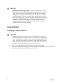
Installing the Server Board
CAUTION
The server board can be extremely sensitive to ESD and always requires
careful handling. After removing it from the server, place it component side
up on a nonconductive, static free surface to prevent shorting out the battery
leads. If you place the board on a conductive surface, the battery leads may
short out. If they do, this will result in a loss of CMOS data and will drain
the battery. Do not slide the server board over any surface.
1. Observe the safety and ESD precautions at the beginning of this chapter.
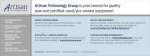
2. Insert screws through the mounting holes and into the threaded standoffs. Make sure the board
is properly seated, and then tighten all the screws firmly.
26
Upgrading
OM08500
Figure 3. Server Board Screw Hole Locations
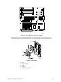
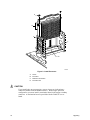
3. Install the two fans (A) into one of the retention mechanism ends (E) label side out so the
airflow (B) flows away from the processors. Use two screws (D) to hold each fan in place.
E
D
B
A
B
C
OM07681
Figure 4. Install Fans
A. Fan
B. Airflow direction
C. Cable
D. Screws
E. Retention mechanism
C440GX+ Server Board Product Guide
27
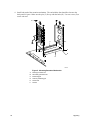
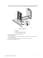
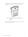
4. Install both ends of the retention mechanism. The end with the fans should be closest to the
back panel I/O ports. Make sure the pins (C) line up with the holes (D). Use two screws (F) to
secure each end.
F
A
C
E
D
B
OM07684
Figure 5. Mounting Retention Mechansim
A.
B.
C.
D.
E.
F.
28
Primary processor slot
Secondary processor slot
Positioning pin
Hole for positioning pin
Screw hole
Screws
Upgrading
5. Connect the fan cables to the server board. The top fan (A) connects to the PROC FAN2 TOP
fan connector (C). The bottom fan (B) connects to the PROC FAN1 BTM fan connector (D).
A
B
C
D
OM07685
Figure 6. Install Fans
A.
B.
C.
D.
Top fan
Bottom fan
PROC FAN2 TOP connector (J7B1)
PROC FAN1 BTM connector (J6A1)
6. Connect all internal cables to the server board.
7. Reinstall add-in boards.
8. Connect all internal cables to add-in boards. Make sure you connect the power cables to the
correct power connectors.
9. Connect all peripheral device cables to the I/O panel on the rear of the server.
10. Run the SSU to configure the server.
C440GX+ Server Board Product Guide
29
Removing the Server Board
CAUTION
The server board can be extremely sensitive to ESD and always requires
careful handling. After removing it from the server, place it component side
up on a nonconductive, static free surface to prevent shorting out the battery
leads. If you place the board on a conductive surface, the battery leads may
short out. If they do, this will result in a loss of CMOS data and will drain
the battery. Do not slide the server board over any surface.
1. Observe the safety and ESD precautions at the beginning of this chapter.
2. Open the server and remove peripherals and components blocking access to the server board.
See your chassis manual for more information.
3. Label and disconnect all internal cables connected to add-in boards.
4. Remove all add-in boards.
5. Label and disconnect all internal cables connected to the server board.
6. Remove the server board retaining screws and set them aside.
7. Remove the server board, and place it component side up on a nonconductive, static free
surface or in an antistatic bag.
8. If present, remove and save the EMI gasket that covers the I/O connectors on the board.
30
Upgrading
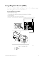
Voltage Regulator Modules (VRMs)
You must install a VRM in the P1 Primary VRM socket. If you install a secondary processor, you
must also install a VRM in the P2 Secondary VRM Socket. You may install 5 V or 12 V VRMs.
See the following URL for information on which URM to use:
http://www.intel.com/go/serverbuilder/
Look under Reference Chassis.
1.
2.
3.
4.
Observe the safety and ESD precautions at the beginning of this chapter.
Open your server.
Remove the VRM from its antistatic packaging.
Insert the VRM into the socket component side facing the center of the server board.
C
B
A
OM07716
Figure 7. Installing a VRM
A. Socket
B. Locking tab
C. VRM
C440GX+ Server Board Product Guide
31
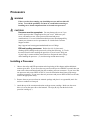
Processors
WARNING
If the server has been running, any installed processor and heat sink will
be hot. To avoid the possibility of a burn, be careful when removing or
installing server board components that are located near processors.
CAUTIONS
Processor must be appropriate: You may damage the server if you
install a processor that is inappropriate for your server. Make sure your
server can handle a newer, faster processor (thermal and power
considerations). For exact information about processor interchangeability,
contact your customer service representative or visit the Intel Customer
Support website:
http://support.intel.com/support/motherboards/server/C440gx
ESD and handling processors: Reduce the risk of electrostatic
discharge (ESD) damage to the processor by doing the following: (1) Touch
the metal chassis before touching the processor or server board. Keep part
of your body in contact with the metal chassis to dissipate the static charge
while handling the processor. (2) Avoid moving around unnecessarily.
Installing a Processor
1. Observe the safety and ESD precautions at the beginning of this chapter and the additional
cautions given here. If your server has one processor and you are ADDING a second, then you
must remove the termination board from the secondary processor connector. If your server has
one processor and you are REPLACING it, leave the termination board intact in the empty
secondary connector. If your server has two processors and you are REPLACING one or both,
remove the appropriate one(s).
2. Remove the new processor from its antistatic package and place it on a grounded, static free
surface or conductive foam pad.
3. Attach the top of the retention mechanism to the processor cartridge. Make sure the screw
holes (A) are on the same side as the heatsink. The clips (B) clip into the holes in the
processor cartridge (C).
32
Upgrading
B
A
C
OM07689
Figure 8. Attach Retention Mechansim to Processor
A. Screw hole
B. Locking tab
C. Hole
✏
NOTE
If you are installing the processor in the secondary processor slot, the screw
holes (A) are on the side away from the heatsink.
4. Slide the processor (B) nto the retention mechanism (C) and press it firmly into its slot (D).
Secure the processor with two screws (A).
C440GX+ Server Board Product Guide
33
A
B
C
D
OM07690
Figure 9. Install Processor
A. Screw
B. Processor
C. Retention mechanism
D. Processor slot
CAUTION
If you install only one processor in a system, it must go in the primary
connector (farthest from the DIMM sockets). With a single-processor
configuration, you must install a termination board in the empty secondary
connector. A termination board is provided with the C440GX+ server
board.
34
Upgrading
5. Attach the top of the retention mechanism to the termination card assembly. Make sure the
screw holes (A) are on the rear of the assembly. The clips (B) clip into the holes in the
assembly (C).
A
B
C
OM07692
Figure 10. Attaching the Retention Mechansim to the Termination Card
A. Screw hole
B. Locking tab
C. Hole
6. Slide the termination card assembly into the retention mechanism and press it firmly into its
slot. Secure the assembly with two screws (A).
C440GX+ Server Board Product Guide
35
A
OM07694
Figure 11. Install the Termination Card
A.
Screw
Removing a Processor
1. Observe the safety and ESD precautions at the beginning of this chapter and the additional
cautions given here.
2. As you work, place boards and processors on a grounded, static free surface or conductive
foam pad.
3. Remove the two screws hold the processor to the retention mechansim.
4. Lift the processor cartridge upward, out of the retention mechansim.
5. Put the processor in a piece of conductive foam and store in an antistatic package.
36
Upgrading
Memory
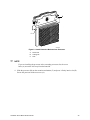
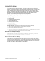
Installing DIMMs
CAUTIONS
Use extreme care when installing a DIMM. Applying too much pressure can
damage the socket. DIMMs are keyed and can be inserted in only one way.
Mixing dissimilar metals may cause later memory failures resulting in data
corruption. Only install DIMMs with gold-plated edge connectors in goldplated sockets.
See Chapter 1 for memory size and requirements.
1. Observe the safety and ESD precautions at the beginning of this chapter.
2. Open your server.
3. Holding the DIMM only by its edges, remove it from its antistatic package.
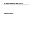
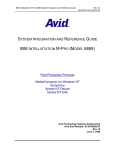
4. Orient the DIMM so that the two notches in the bottom edge of the DIMM align with the
keyed socket.
5. Insert the bottom edge of the DIMM into the socket, and press down firmly on the DIMM until
it seats correctly.
6. Gently push the plastic ejector levers on the socket ends to the upright position.
7. Repeat the steps to install each DIMM.
8. Close the server.
9. Connect all external cables and the power cord to the server.
10. Turn on the monitor and then the server.
1234
1
OM08501
Figure 12. Installing DIMMs
C440GX+ Server Board Product Guide
37
Removing DIMMs
CAUTION
Use extreme care when removing a DIMM. Too much pressure can damage
the socket slot. Apply only enough pressure on the plastic ejector levers to
release the DIMM.
1.
2.
3.
4.
5.
6.
7.
8.
38
Observe the safety and ESD precautions at the beginning of this chapter.
Open the server.
Gently push the plastic ejector levers out and down to eject a DIMM from its socket.
Hold the DIMM only by its edges, being careful not to touch its components or gold edge
connectors. Carefully lift it away from the socket, and store it in an antistatic package.
Repeat to remove other DIMMs as necessary.
Close the server.
Connect all external cables and the power cord to the server.
Turn on the monitor and then the server.
Upgrading
Replacing the Back up Battery
The lithium battery on the server board powers the real time clock (RTC) for up to 10 years in the
absence of power. When the battery starts to weaken, it loses voltage, and the server settings
stored in CMOS RAM in the RTC (for example, the date and time) may be wrong. Contact your
customer service representative or dealer for a list of approved devices.
WARNING
Danger of explosion if battery is incorrectly replaced. Replace only with
the same or equivalent type recommended by the equipment
manufacturer. Discard used batteries according to manufacturer’s
instructions.
ADVARSEL!
Lithiumbatteri - Eksplosionsfare ved fejlagtig håndtering. Udskiftning
må kun ske med batteri af samme fabrikat og type. Levér det brugte
batteri tilbage til leverandøren.
ADVARSEL
Lithiumbatteri - Eksplosjonsfare. Ved utskifting benyttes kun batteri
som anbefalt av apparatfabrikanten. Brukt batteri returneres
apparatleverandøren.
VARNING
Explosionsfara vid felaktigt batteribyte. Använd samma batterityp eller
en ekvivalent typ som rekommenderas av apparattillverkaren. Kassera
använt batteri enligt fabrikantens instruktion.
VAROITUS
Paristo voi räjähtää, jos se on virheellisesti asennettu. Vaihda paristo
ainoastaan laitevalmistajan suosittelemaan tyyppiin. Hävitä käytetty
paristo valmistajan ohjeiden mukaisesti.
C440GX+ Server Board Product Guide
39
OM08502
Figure 13. Replacing the Lithium Battery
1. Observe the safety and ESD precautions at the beginning of this chapter.
2. Open the chassis.
3. Insert the tip of a small flat bladed screwdriver, or equivalent, under the tab in the plastic
retainer.
4. Gently push down on the screwdriver to lift the battery.
5. Remove the battery from its socket.
6. Dispose of the battery according to local ordinance.
7. Remove the new lithium battery from its package, and, being careful to observe the correct
polarity, insert it in the battery socket.
8. Reinstall the plastic retainer on the lithium battery socket.
9. Close the chassis.
10. Run the SSU to restore the configuration settings to the RTC.
40
Upgrading
3 Configuration Software and Utilities
This chapter describes the Power On Self Test (POST) and server configuration utilities. The table
below briefly describes the utilities.
Table 4.
Configuration Utilities
Utility
Description and brief procedure
Page
BIOS Setup
If the system does not have a diskette drive, or the drive is disabled or
misconfigured, use Setup to enable it.
43
Or, you can move the CMOS jumper on the server board from the default
setting (Protect CMOS memory) to the Clear setting; this will allow most
server configurations to boot. For the procedure to do this, see the section
“CMOS Jumper” in Chapter 5 in this manual. Then run the SSU to configure
the server.
System Setup
Utility (SSU)
Use for extended system configuration of onboard resources and add-in
boards, and for viewing the system event log, setting boot device priority, or
setting system security options.
57
The SSU may be run from either the Server Configuration CD or from a DOSbootable diskette.
Information entered via the SSU overrides information entered via BIOS
Setup.
EMP Console
Use to access and monitor the server remotely.
68
FRUSDR Load
Utility
Use to update the Field Replacement Unit (FRU), Sensor Data Record (SDR),
and Desktop Management Interface (DMI) flash components.
81
BIOS Update
Utility
Use to update the BIOS or recover from a corrupted BIOS update.
85
Firmware Update
Utility
Use to update BMC flash ROM.
88
Using the Adaptec
SCSI Utility
Use to configure or view the settings of the SCSI host adapters and onboard
SCSI devices in the server.
89
Hot Keys
Use the keyboard’s numeric pad to enter numbers and symbols.
Table 5.
Hot Keys
To do this:
Press these keys
Clear memory and reload the operating
systemthis is a system reset.
<Ctrl+Alt+Del>
Secure your system immediately.
<Ctrl+Alt>+hotkey (Set your hot key combination with the
SSU or Setup.)
41
Power On Self Test (POST)
Each time you turn on the system, POST starts running. POST checks the server board, processor,
memory, keyboard, and most installed peripheral devices. During the memory test, POST displays
the amount of memory that it is able to access and test. The length of time needed to test memory
depends on the amount of memory installed. POST is stored in flash memory.
1. Turn on your video monitor and server. After a few seconds POST begins to run.
2. After the memory test, these screen prompts and messages appear:
Press <F2> key if you want to run SETUP
Keyboard.....Detected
Mouse........Detected
3. If you do not press <F2> and do NOT have a device with an operating system loaded, the
above message remains for a few seconds while the boot process continues, and the system
beeps once. Then this message appears:
Operating system not found
If you do not press <F2> and DO have an operating system loaded, the boot process continues,
and this message appears:
Press <Ctrl><A> to enter SCSI Utility
4. Press <Ctrl+A> if there are SCSI devices installed. When the utility opens, follow the
displayed instructions to configure the onboard SCSI host adapter settings and to run the
SCSI utilities. Also see “Using the Adaptec SCSI Utility” on page 89. If you do not enter the
SCSI utility, the boot process continues.
5. Press <Esc> during POST to pop up a boot menu when POST finishes. From this menu you
can choose the boot device or enter BIOS Setup.
After POST completes, the system beeps once.
What appears on the screen after this depends on whether you have an operating system loaded and
if so, which one.
If the system halts before POST completes running, it emits a beep code indicating a fatal system
error that requires immediate attention. If POST can display a message on the video display
screen, it causes the speaker to beep twice as the message appears.
Note the screen display and write down the beep code you hear; this information is useful for your
service representative. For a listing of beep codes and error messages that POST can generate, see
the “Solving Problems” chapter in this manual.
42
Configuration Software and Utilities
Using BIOS Setup
This section describes the BIOS Setup options. Use Setup to change the server configuration
defaults. You can run Setup with or without an operating system being present. Setup stores most
of the configuration values in battery backed CMOS; the rest of the values are stored in flash
memory. The values take effect when you boot the server. POST uses these values to configure
the hardware; if the values and the actual hardware do not agree, POST generates an error
message. You must then run Setup to specify the correct configuration.
Run Setup: You may run Setup to modify such server board feature as:
•
•
•
•
•
•
•
•
Select diskette drive
Select parallel port
Select serial port
Set time/date (to be stored in RTC)
Configure IDE hard drive
Specify boot device sequence
Enable SCSI BIOS
Specify processor speed
Run SSU, not Setup: You must run the SSU instead of Setup to do the following:
•
•
•
Add or remove any ISA board that is not Plug and Play-compatible
Enter or change information about a board
Alter server resources (such as interrupts, memory addresses, I/O assignments) to user selected
choices instead of choices selected by the BIOS resource manager
Record Your Setup Settings
If the default values ever need to be restored (after a CMOS clear, for example), you must run
Setup again. Referring to the worksheets could make your task easier.
If You Cannot Access Setup
If the diskette drive is misconfigured so that you cannot access it to run a utility from a diskette,
you may need to clear CMOS memory. You will need to open the server, change a jumper setting,
use Setup to check and set diskette drive options, and change the jumper back. For a step-by-step
procedure, see Chapter 5, under the heading, “CMOS Jumper.”
C440GX+ Server Board Product Guide
43
Starting Setup
You can enter and start Setup under several conditions:
•
•
•
When you turn on the server, after POST completes the memory test
When you reboot the server by pressing <Ctrl+Alt+Del> while at the DOS operating system
prompt
When you have moved the CMOS jumper on the server board to the “Clear CMOS” position
(enabled); for the procedure, see Chapter 5, under the heading “CMOS Jumper”
In the three conditions listed above, after rebooting, you will see this prompt:
Press <F2> to enter SETUP
In a fourth condition, when CMOS/NVRAM has been corrupted, you will see other prompts but
not the <F2> prompt:
Warning:
Warning:
cmos checksum invalid
cmos time and date not set
In this condition, the BIOS will load default values for CMOS and attempt to boot.
Setup Menus
To:
Press
Get general help
<F1> or <Alt+H>
Move between menus
←→
Go to the previous item
↑
Go to the next Item
↓
Change the value of an item
+ or -
Select an item or display a submenu
<Enter>
Leave a submenu or exit Setup
<Esc>
Reset to Setup defaults
<F9>
Save and exit Setup
<F10>
When you see this:
What it means
On screen, an option is shown but you
cannot select it or move to that field.
You cannot change or configure the option in that menu screen.
Either the option is autoconfigured or autodetected, or you must
use a different Setup screen, or you must use the SSU.
On screen, the phrase Press Enter
appears next to the option.
Press <Enter> to display a submenu that is either a separate full
screen menu or a popup menu with one or more choices.
The rest of this section lists the features that display onscreen after you press <F2> to enter Setup.
Not all of the option choices are described, because (1) a few are not user selectable but are
displayed for your information, and (2) many of the choices are relatively self explanatory.
44
Configuration Software and Utilities
Main Menu
You can make the following selections on the Main Menu itself. Use the submenus for other
selections.
Feature
Choices
Description
System Time
HH:MM:SS
Sets the system time.
System Date
MM/DD/YYYY
Sets the system date.
Legacy Diskette A:
Disabled
360KB
1.2 MB
720KB
1.44/1.25 MB
2.88 MB
Selects the diskette type.
Legacy Diskette B:
Disabled
360KB
1.2 MB
720KB
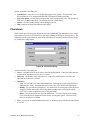
1.44/1.25 MB
2.88 MB
Primary IDE Master
Enters submenu.
Primary IDE Slave
Enters submenu.
Secondary IDE Master
Enters submenu.
Secondary IDE Slave
Enters submenu.
Keyboard Features
Enters submenu.
Processor Setting
Enters submenu.
Language
English (US)
Français
Español
Deutsch
Italiano
C440GX+ Server Board Product Guide
Selects which language BIOS displays.
45
Primary/Secondary IDE Master and Slave Submenu
Feature
Choices
Description
Type
Auto
None
CD-ROM
IDE Removable
Auto forces the server to attempt autodetection of the drive type.
None informs the server to ignore this drive.
CD ROM allows the manual entry of some fields described below.
IDE Removable allows the manual entry of some fields described
below.
ATAPI Removable allows the manual entry of some fields
described below.
User allows the manual entry of all fields described below.
ATAPI Removable
User
CHS Format
Cylinders
0 to 65535
Number of Cylinders on Drive.
This field is changeable only for Type User.
Heads
1 to 16
Number of read/write heads on drive.
This field is available only for Type User.
Sectors
0 to 63
Number of sectors per track.
This field is available only for Type User.
Maximum
Capacity
N/A
Computed size of drive from cylinders, heads, and sectors
entered. This field is informational only.
Total Sectors
N/A
This field is informational only.
Maximum
Capacity
N/A
This field is informational only.
Multi-Sector
Transfer
Disabled
2, 4, 8, or 16
sectors
Determines the number of sectors per block for multi-sector
transfers.
This field is informational only for Type Auto.
LBA Mode
Control
Disabled
Enabled
Enabling LBA causes logical block addressing to be used in place
of cylinders, heads, and sectors.
This field is informational only for Type Auto.
32 Bit I/O
Disabled
Enabled
Enabling allows 32 bit IDE data transfers.
Transfer Mode
Standard
Fast PIO 1
Fast PIO 2
Fast PIO 3
Fast PIO 4
FPIO 3 / DMA 1
FPIO 4 / DMA 2
Selects the method for moving data to and from the drive.
This field is informational only for Type Auto.
Ultra DMA
Mode
Disabled
Mode 0
Mode 1
Mode 2
Selects the Ultra DMA mode used for moving data to/from the
drive.
LBA Format
46
Configuration Software and Utilities
Keyboard Submenu
Feature
Choices
Description
Num Lock
On
Off
Selects the power on state for Num Lock.
Key Click
Disabled
Enabled
Enables or disables the audible key click.
Keyboard auto-repeat rate
30/sec
26.7/sec
21.8/sec
18.5/sec
13.3/sec
10/sec
6/sec
2/sec
Sets the numbers of time per second a key will repeat
while it is held down.
Keyboard auto-repeat delay
1/4 sec
1/2 sec
3/4 sec
1 sec
Sets the delay before a key starts to repeat when it is
held down.
Processor Setting Submenu
Feature
Choices
Description
CPU Post Speed Setting
450 MHz
450 MHz
500 MHz
Sets the speed for the installed processor.
Processor Retest
No
Yes
Yes tells BIOS to clear the historical processor status
and retest all processors on the next boot. BIOS
automatically resets to No in next boot.
Memory Cache
Enabled
Disabled
Enables processor cache.
Processor 1 Stepping ID
N/A
This field is informational only.
Processor 1 L2 Cache Size
N/A
This field is informational only.
Processor 2 Stepping ID
N/A
This field is informational only.
Processor 2 L2 Cache Size
N/A
This field is informational only.
C440GX+ Server Board Product Guide
47
Advanced Menu
You can make the following selections on the Advanced Menu itself. Use the submenus for the
three other selections that appear on the Advanced Menu.
Feature
Choices
Description
Installed OS
Other
Win95
Select Win95 if you are booting a Plug and Play capable
operating system.
Reset Configuration Data
No
Yes
Select Yes if you want to clear the server configuration
data during next boot. System automatically resets to No
in next boot.
PCI Configuration
Enters submenu.
Integrated Peripherals
Configuration
Enters submenu.
Advanced Chipset Control
Enters submenu.
Use Multiprocessor
Specification
1.1
1.4
Selects the version of multiprocessor specification to use.
Some operating systems do not support version 1.4.
Large Disk Access Mode
CHS
LBA
Select CHS if your OS is DOS. A large disk has more than
1024 cylinders, more than 16 heads, or more than 63
tracks per sector.
Delay on Option ROMs
Disabled
Enabled
Forces a short delay at the end of each Option ROM scan.
PCI Configuration Submenu
The PCI Configuration Menu contains selections that access other submenus.
PCI Device, Embedded SCSI Submenu
48
Feature
Choices
Description
Option ROM Scan
Enabled
Disabled
Enables option ROM scan of the onboard SCSI chip.
There are 2 SCSI channels that are controlled by the same
option ROM.
Enable Master
Enabled
Disabled
Enabled selects the device as a PCI bus master.
Latency Timer
Default
0020h
0040h
0060h
0080h
00A0h
00C0h
00E0h
Minimum guaranteed time, in units of PCI bus clocks, that
a device may be master on a PCI bus.
CAUTION
Do not change this setting unless you fully
understand the priority of this device on the
PCI bus.
Configuration Software and Utilities
PCI Device, Slot 1 - Slot 6 Submenus
Feature
Choices
Description
Enable Master
Enabled
Disabled
Enables selected device as a PCI bus master.
Latency Timer
Default
020h
040h
060h
080h
0A0h
0C0h
0E0h
Minimum guaranteed time, in units of PCI bus clocks, that
a device may be master on a PCI bus.
CAUTION
Do not change this setting unless you fully
understand the priority of this device on the PCI bus.
Integrated Peripheral Configuration Submenu
Feature
Choices
Description
COM 1
Disabled
Enabled
Auto
OS Controlled
Auto forces BIOS to configure the port.
OS Controlled Forces the OS to configure the port.
Base I/O Address
3F8
2F8
3E8
2E8
Selects the base I/O address for COM 1.
Interrupt
IRQ 3
IRQ 4
Selects the IRQ for COM 1.
COM2
Disabled
Enabled
Auto
PnP OS
Auto forces BIOS to configure the port.
PnP OS forces OS configures the port.
Base I/O Address
3F8
2F8
3E8
2E8
Selects the base I/O address for COM2.
Interrupt
IRQ 3
IRQ 4
Selects the IRQ for COM2.
Parallel Port
Disabled
Enabled
Auto
PnP OS
Auto forces BIOS to configure the port.
PnP OS forces OS configures the port.
Mode
Output only
Bi-directional
EPP
ECP
Selects parallel port mode.
Base I/O Address
378
278
Selects the base I/O address for LPT port.
continued
C440GX+ Server Board Product Guide
49
Integrated Peripheral Configuration Submenu (continued)
Feature
Choices
Description
Interrupt
IRQ 5
IRQ 7
Selects the IRQ for LPT port.
DMA channel
DMA 1
DMA 3
Selects the DMA for LPT port (only used for ECP mode).
Floppy disk controller
Disabled
Enabled
Enables onboard diskette controller.
Advanced Chipset Control
50
Feature
Choices
Description
640-768K Memory
Region
Enabled
Disabled
Enabled forwards ISA Master and DMA cycles to the PCI
bus. Disabled forwards these cycles to memory.
Delayed Transaction
Enabled
Disabled
Enables the delayed transaction mechanism when the
PIIX4e is the target of a PCI transaction.
Passive Release
Enabled
Disabled
Enables the passive release mechanism on the PHOLD#
signal when the PIIX4 is a PCI Master.
Configuration Software and Utilities
Security Menu
You can make the following selections on the Security Menu itself. Enabling the Supervisor
Password field requires a password for entering Setup. The passwords are not case-sensitive.
Feature
Choices
Description
User Password is
Clear
Set
Status only; user cannot modify. Once set, this can be disabled
by setting it to a null string, or by clearing password jumper on
server board.
Supervisor Password is
Clear
Set
Status only; user cannot modify.
Set User Password
Press Enter
When the <Enter> key is pressed, you are prompted for a
password; press ESC key to abort. Once set, this can be cleared
by setting it to a null string, or by clearing password jumper on
server board (see Server Board Jumpers in Chapter 5).
Set Supervisor
Password
Press Enter
When the <Enter> key is pressed, you are prompted for a
password; press ESC key to abort. Once set, this can be cleared
by setting it to a null string, or by clearing password jumper on
server board (see Server Board Jumpers in Chapter 5).
Password on Boot
Disabled
Enabled
Requires password entry before boot. System will remain in
secure mode until password is entered. Password on Boot takes
precedence over Secure Mode Boot.
Fixed Disk Boot Sector
Normal
Write
Protect
Write protects boot sector on hard disk to protect against viruses.
Secure Mode Timer
Disabled
1 min
2 min
5 min
10 min
20 min
1 hr
2 hr
Period of key/PS/2 mouse inactivity specified for secure mode to
activate. A password is required for secure mode to function.
Cannot be enabled unless at least one password is enabled.
Secure Mode Hot Key
(Ctrl-Alt- )
[]
[A, B, ..., Z]
Key assigned to start the Quicklock feature. Cannot be enabled
unless at least one password is enabled.
Secure Mode Boot
Disabled
Enabled
System will boot in secure mode. You must enter a password to
unlock the system. Cannot be enabled unless at least one
password is enabled.
Video Blanking
Disabled
Enabled
Blank video when secure mode is activated. You must enter a
password to unlock the system. Cannot be enabled unless at
least one password is enabled.
Floppy Write Protect
Disabled
Enabled
When secure mode is activated, the diskette drive is write
protected. You must enter a password to disable. Cannot be
enabled unless at least one password is enabled.
Front Panel Lockout
Disabled
Enabled
When secure mode is activated, the reset and power switches are
locked. You must enter a password to unlock the system.
Cannot be enabled unless at least one password is enabled.
C440GX+ Server Board Product Guide
51
Server Menu
You can make the following selections on the Server Menu itself.
Feature
Choices
Description
System Management
Enters submenu.
Console Redirection
Enters submenu.
Enable Sleep Button
Disabled
Enabled
PCI IRQs to IO-APIC
mappings
Disabled
Enabled
Enabled - BIOS can describe all 24 IO APIC pins in the
MP table for PCI interrupts. Not all MP operating
systems and drivers can understand this description of
the interrupts in the MP table.
Disabled - BIOS will only use 16 IO APIC pins in the MP
table for PCI interrupts. All PCI interrupts are routed to a
standard ISA IRQ pins on IO APIC. All operating
systems will work with standard ISA IRQ entries.
Processor Retest
Yes
No
Yes tells BIOS to clear the historical processor status
and retest all processors on the next boot. BIOS
automatically resets to No in next boot.
Assert NMI on PERR
Disabled
Enabled
Enabled generates an NMI on a parity error (PERR). To
activate this feature, the system error (SERR) option
must be enabled.
Assert NMI on SERR
Disabled
Enabled
Enabled generates an NMI on SERR.
System Management Submenu
Feature
Choices
Server Management
Info
Description
Enters submenu.
System Event
Logging
Disabled
Enabled
When enabled, system events will be logged by BIOS
and BMC in system event log.
Clear Event Log
No
Yes
Yes clears the system event log (SEL) in BMC. BIOS
automatically resets to NO for next boot.
EMP Password switch
Disabled
Sets the EMP password.
Enabled
EMP Password
[A..Z, 0..9]
This field only shows up when the EMP password switch
is enabled. Entering a password and pressing return will
send the password immediately to the BMC. If a beep is
heard the password was not accepted. If no password is
entered, anyone has access to the server through the
EMP Console.
EMP Escape
sequence
+++
Sets the escape sequence for the modem being used for
EMP. This will force the modem to command mode.
This is only used if the EMP direct connect/modem mode
is set to modem.
continued
52
Configuration Software and Utilities
System Management Submenu (continued)
Feature
Choices
Description
EMP Hangup Line
String
ATH
Sets the Hangup Line Sequence for the modem being
used for EMP. Used in EMP modem mode.
Modem Init String
AT&F0S0=1S14=0&D
Sets the initialization string for the modem being used for
EMP. Used in EMP modem mode.
This field is only 16 characters long. The High Modem
Init String field is a continuation of the Modem Init string
so you can enter in another 4 characters.
High Modem Init
String
0
This is a continuation of the Modem Init String. When 16
characters are typed into the Modem Init String field, this
field will appear to allow another 4 characters to be
typed in.
EMP Access Mode
Pre-boot Only
Pre-boot Only - EMP is only enabled during power down
through end of POST. COM2 is returned to system use
at the end of Post when operating system boots.
Always Active - EMP is always enabled. COM2 cannot
be used by operating system. It is now dedicated for
EMP use.
Disabled – EMP is disabled. COM2 is always available
for system use by console redirection or operating
system.
Always Active
Disabled
EMP Restricted
Mode Access
Disabled
Enabled
If set to Enabled, Power on/off and Reset server controls
via EMP are no longer available.
EMP Direct
Connect/Modem
Mode
Direct Connect
Sets how EMP connects to the server. Direct Connect
means a null modem serial cable directly connects
COM2 connector port to the EMP console machine.
Modem Mode
Modem mode indicates that a modem is connected on
COM2 for EMP use.
Server Management Information Submenu
Items on this menu are set when the server board is manufactured and cannot normally be changed.
The last two items refer to the firmware level of the BMC on the server board and HSC (Hot Swap
Controller) from the Astor II server chassis. If circumstances require a change in the C440GX+
server board’s firmware, specific direction will be provided by Intel Customer Support.
Feature
Choices
Description
Board Part Number
N/A
Information field only
Board Serial Number
N/A
Information field only
System Part Number
N/A
Information field only
System Serial Number
N/A
Information field only
Chassis Part Number
N/A
Information field only
Chassis Serial Number
N/A
Information field only
BMC Revision
N/A
Information field only
Primary HSB Revision
N/A
Information field only
C440GX+ Server Board Product Guide
53
Console Redirection Submenu
Feature
Choices
Description
COM Port Address
Disabled
3F8
2F8
3E8
When enabled, console redirection uses the I/O port specified.
3F8 - typically is COM 1
2F8 - typically is COM2
All keyboard/mouse and video will be directed to this port. This
is designed to be used only under DOS in text mode.
IRQ #
N/A
This field is informational only.
Baud Rate
9600
19.2k
38.4k
115.2k
When console redirection is enabled, specifies the baud rate to
be used.
Flow Control
No Flow Control
CTS/RTS
XON/XOFF
CTS/RTS + CD
None disallows flow control.
CTS/RTS is hardware-flow control.
XON/XOFF is software-flow control.
CTS/RTS +CD is hardware plus carrier-detect flow control.
Boot Menu
You can make the following selections on the Boot Menu itself.
54
Feature
Choices
Boot-time Diagnostic
Screen
Disabled
Enabled
Description
Boot Device Priority
Enters submenu.
Hard Drive
Enters submenu.
Removable Devices
Enters submenu.
Configuration Software and Utilities
Boot Device Priority
Use the up or down arrow keys to select a device; then press the <+> or <-> keys to move the
device higher or lower in the boot priority list.
Boot Priority
Device
Description
1.
Removable Devices
Attempts to boot from a removable media device.
2.
Hard Drive
Attempts to boot from a hard drive device.
3.
ATAPI CD-ROM Drive
Attempts to boot from an ATAPI CD-ROM drive.
4.
LANDesk (R) Service Agent II
Attempts to boot from the local area network.
Hard Drive
For options on this menu, use the up or down arrow keys to select a device; then press the <+> or
<-> keys to move the device higher or lower in the boot priority list.
Option
Description
1. Hard Drive #1 (or actual drive string)
IDE drives will have a suffix attached to the drive ID string.
PM - hard drive on Primary Master Channel
PS - hard drive on Primary Slave Channel
SM - hard drive on Secondary Master Channel
SS - hard drive on Secondary Slave Channel
SCSI CD-ROMs will be displayed here because the onboard
SCSI BIOS treats CD-ROMs as hard drives.
SCSI ZIP or removable drives will also appear here.
Removable IDE ZIP drives will only show up if the removable
media is formatted as a hard drive.
2. Other Bootable Device
Covers all the boot devices that are not reported to the system
BIOS through the BIOS boot specification mechanism. This
includes all PCI cards that are not BIOS boot compliant
(legacy) as well as ISA cards that are not PnP compliant.
ISA legacy cards will boot first before non BIOS boot compliant
PCI cards (in scan order from lowest slot to highest).
Removable Devices
For options on this menu, use the up or down arrow keys to select a device, then press the <+> or
<-> keys to move the device higher or lower in the boot priority list.
Option
Description
1. Legacy Floppy Drive
Refers to the onboard 3.5” floppy drive.
Removable IDE media may also show up here if the removable
media was formatted in floppy emulation.
C440GX+ Server Board Product Guide
55
Exit Menu
You can make the following selections on the Exit Menu. Select an option using the up or down
arrow keys; then press <Enter> to execute the option. Pressing <Esc> does not exit this menu.
You must select one of the items from the menu or menu bar to exit.
56
Choices
Description
Exit Saving Changes
Exits after writing all modified Setup item values to NVRAM.
Exit Discarding Changes
Exits leaving NVRAM unmodified.
Load Setup Defaults
Loads values of all Setup items from previously saved custom defaults.
Load Custom Defaults
Loads default values for all Setup items.
Save Custom Defaults
Saves present Setup values to custom defaults.
Discard Changes
Reads previous values of all Setup items from NVRAM.
Save Changes
Writes all Setup item values to NVRAM.
Configuration Software and Utilities
Using the System Setup Utility
The System Setup Utility (SSU) is on the C440GX+ Server Board Resource software CD shipped
with the server board. The SSU provides a graphical user interface (GUI) over an extensible
framework for server configuration. For the C440GX+ systems, the SSU framework supports the
following functions and capabilities:
•
•
•
•
•
assigns resources to baseboard devices and add-in cards prior to loading the operating
system (OS)
allows you to specify boot device order and system security options
permits viewing and clearing of the system’s critical event log
allows troubleshooting of the server when the OS is not operational
provides a system level view of the server’s I/O devices
When to Run the System Setup Utility
The SSU is a DOS-based utility that supports extended system configuration operations for
onboard resources and add-in boards. You can also view the system event log and to set system
boot and security options. Use the SSU when you need to
•
•
•
•
•
add and remove boards affecting the assignment of resources (ports, memory, IRQs, DMA)
modify the server’s boot device order or security settings
change the server configuration settings
save the server configuration
view or clear the system event log
If you install or remove an ISA add-in board, you must run the SSU to reconfigure the server.
Running the SSU is optional for PCI and Plug and Play ISA add-in boards.
The SSU is PCI aware, and it complies with the ISA Plug and Play specifications. The SSU works
with any compliant configuration (.CFG) files supplied by the peripheral device manufacturer.
The I/O baseboard comes with a .CFG file. The .CFG file describes the characteristics of the
board and the system resources that it requires. The configuration registers on PCI and ISA Plug
and Play add-in boards contain the same type of information that is in a .CFG file. Some
ISA boards also come with a .CFG file.
The SSU uses the information provided by .CFG files, configuration registers, flash, and the
information that you enter, to specify a system configuration. The SSU writes the configuration
information to flash memory.
The SSU stores configuration values in flash memory. These values take effect when you boot the
server. POST checks the values against the actual hardware configuration; if they do not agree,
POST generates an error message. You must then run the SSU to specify the correct configuration
before the server boots.
The SSU always includes a checksum with the configuration data so the BIOS can detect any
potential data corruption before the actual hardware configuration takes place.
C440GX+ Server Board Product Guide
57
What You Need to Do
The SSU may be run directly from the Server Resource CD by booting the server system to the CD
and selecting “Utilities” or from a set of DOS diskettes.
If you choose to run the SSU from a set of DOS diskettes, you must create the SSU diskettes from
the Server Resource CD by booting to the CD and selecting “Create Diskettes.” Alternatively, if
you have a Windows† 95 or Windows NT workstation, you can insert the CD into that system and
create diskettes from the “Utilities” menu of the graphical user interface.
If your diskette drive is disabled, or improperly configured, you must use the flash resident Setup
utility to enable it so that you can use the SSU. If necessary, you can disable the drive after you
exit the SSU. Information entered using the SSU overrides any entered using Setup.
Running the SSU
•
•
58
Running the SSU Locally
Running the ssu.bat file provided on the SSU media starts the SSU. If the server boots directly
from the SSU media, the ssu.bat file is automatically run. If it boots from a different media,
the SSU can be started manually or by another application. When the SSU starts in the local
execution mode (the default mode), the SSU accepts input from the keyboard and/or mouse.
The SSU presents a VGA based Graphical User Interface (GUI) on the primary monitor.
The SSU runs from writable, nonwritable, removable, and nonremovable media. If the SSU is
run from nonwritable media, user preference settings (such as screen colors) can not be saved.
The SSU supports the ROM-DOS V6.22 operating system. It may run on other ROM-DOScompatible operating systems but they are not supported. The SSU will not operate from a
“DOS box” running under an operating system such as Windows.
Running the SSU Remotely
Running the SSU remotely requires a remote server with a LANDesk Emergency Management
Card 2 (EMC2) card and a local system with Remote Control software available.
The EMC2 card provides video memory, keyboard, and mouse redirection support for the
remote server. The Remote Control console of the local system displays and sends video
memory and user input to the remote server through either a modem or an Ethernet link.
Because the SSU runs exclusively on the remote server, any files required for the SSU to run
must be available on the remote server (on removable or nonremovable media).
If you connect the local system to the remote server through a network or modem you can see
the console, control the mouse, and control the keyboard of the remote server.
Configuration Software and Utilities
Starting the SSU
SSU consists of a collection of task oriented modules plugged into a common framework called
the Application Framework (AF). The Application Framework provides a launching point for
individual tasks and a location for setting customization information. For full functionality the
SSU requires the availability of the AF.INI, AF.HLP, plus any .ADN files and their associated
.HLP and .INI files.
1. Turn on your video monitor and your system.
2. There are two ways to start the SSU.
a. After creating set of three SSU diskettes from the CD: Insert the first SSU diskette in
drive A, and press the reset button or <Ctrl+Alt+Del> to reboot your server from the
diskette.
b. Directly from the Server Resource CD: Insert the Server Resource CD into your
CD ROM drive and press the reset button or <Ctrl-Alt-Del> to reboot. When prompted to
do so, press <F2> to enter BIOS Setup. From the Boot Menu, select the Boot Device
Priority option and then select CD-ROM as your primary boot device. Save those settings
and exit BIOS Setup. The server will boot from the CD-ROM and display a menu of
options. Follow the instructions in the menu to start the SSU.
3. When the SSU title appears on the screen, press <Enter> to continue.
4. The mouse driver loads if it is available; press <Enter> to continue.
5. This message appears:
Please wait while the Application Framework loads....
C440GX+ Server Board Product Guide
59
6. When the main window of the SSU appears, you can customize the user interface before
continuing.
Figure 14. System Setup Utility Main Window
60
Configuration Software and Utilities
Customizing the SSU
The SSU lets you customize the user interface according to your preferences. The AF sets these
preferences and saves them in the AF.INI file so that they take effect the next time you start the
SSU. There are four user customizable settings:
•
•
Color - this button lets you change the default colors associated with different items on the
screen with predefined color combinations. The color changes are instantaneous.
Mode - this button lets you set the desired expertise level.
novice
intermediate
•
•
expert
The expertise level determines which tasks are visible in the Available Tasks section and what
actions each task performs. For a new mode setting to take effect, you must exit the SSU and
restart it.
Language - this button lets you change the strings in the SSU to strings of the appropriate
language. For a new language setting to take effect, you must exit the SSU and restart it.
Other - this button lets you change other miscellaneous options in the SSU. The changes take
effect immediately.
To change the interface default values:
Use the mouse to click on the proper button in the Preferences section of the SSU Main
window.
or
Use the tab and arrow keys to highlight the desired button, and press the spacebar or <Enter>.
or
Access the menu bar with the mouse or hot keys (Alt + underlined letter).
✏
NOTE
If you run the SSU from nonwritable media (like a CD-ROM), these
preferences will be lost when you exit the SSU.
Launching a Task
It is possible to have many tasks open at the same time, although some tasks may require complete
control to avoid possible conflicts. The tasks achieve complete control by keeping the task as the
center of operation until you close the task window.
To launch a task:
1. In the SSU Main window, double click on the task name under Available Tasks to display the
main window for the selected task.
or
Highlight the task name, and click on OK.
or
Use the tab and arrow keys to highlight the desired button, and press the spacebar or <Enter>.
C440GX+ Server Board Product Guide
61
Resource Configuration Add-in (RCA) Window
The RCA provides three major functions:
•
•
•
Creates representations of devices (ISA cards) that cannot be discovered by the system
Modifies the contents of the system by adding and removing devices
Modifies the resources used by devices
You can use the RCA window to define an ISA card or add an ISA card by clicking on the
appropriate button. Removing an ISA card requires that the card be highlighted in the Devices
section of the screen before clicking on the button. You can only add as many ISA cards as you
have ISA slots available.
1. From the SSU main window, launch the RCA by selecting the “Resources” task under the
RCA heading in the task box.
2. When the RCA window appears, it displays messages similar to the following:
Baseboard:
Server board Server board
PCI Card: Bus 00 dev 00 -– Host Processor Bridge
PCI Card: Bus 00 dev 0D –- Multifunction Controller
PCI Card: Bus 00 dev 0F –- Ethernet Controller
PCI Card: Bus 00 dev 12 –- Multifunction Controller
PCI Card: Bus 00 dev 14 –- VGA Controller
3. To configure a device, select its name in the Devices section of the RCA window, and press
the spacebar or <Enter>, or click on it.
4. It is possible to close the RCA window and return to the AF by clicking on the Close button.
Any changes made will be kept in memory for use by the RCA when it is rerun.
5. Save all the changes made by clicking on the Save button. Saving writes your current
configuration to nonvolatile storage where it will be available to the system after every reboot.
6. Closing the window by clicking on the system menu, the dash in the upper left corner, discards
all changes.
Defining an ISA Card
An ISA card usually comes with a vendor created .CFG file that specifies the resources the card
requires to function properly. If the .CFG file is unavailable, you must manually create it or define
the card through the SSU. Defining an ISA card consists of specifying the name of the card and
the resources it consumes. This allows the RCA to consider the ISA card resource requirements
when the RCA tries to resolve conflicts. The information is also used by the system BIOS to
configure the hardware when the system is booted.
1. To add or remove ISA card resources, click on the appropriate resource buttons, select the
desired value, and click on Add or Remove.
2. After you complete the necessary information, click on Save.
3. To edit a card, click on Load to retrieve the card information. After making changes, click
on Save.
4. To create a card, click on New.
5. To remove a current definition of a card, click on Delete.
62
Configuration Software and Utilities
Adding and Removing ISA Cards
Adding and removing cards through the RCA provides a way for the RCA to run its conflict
detection algorithms on the resources requested by the cards. This alerts you to any possible
problems with that particular card in the current configuration.
•
To add an ISA card:
1. Click on Add ISA Card in the RCA window.
2. Specify the directory for the .CFG file.
3. Select the file and click on Ok.
•
To remove an ISA card:
1. Select a valid ISA card in the Devices section of the RCA window.
2. Click on Remove ISA Card.
Modifying Resources
Modifying the resources of a device may be necessary to accommodate certain operating systems,
applications, and drivers. It may also be necessary to modify resources to resolve a conflict.
•
To modify the resources associated with a device:
1. Highlight the device in the Devices section of the RCA window.
2. Press the spacebar or <Enter>, or double click on the entry.
This displays the functions of the selected device along with possible choices and the resources
associated with those choices.
•
To make a modification:
1. Highlight the function in the Configuration window.
2. Press the spacebar or <Enter>, or double click on the entry (this updates the Choice and
resource lists).
3. Press the tab key to get to the Choice list, and press <Enter>.
4. Use the arrow keys to select a proper choice, and press <Enter> again.
5. If the choice allows multiple possible values for a particular resource, use the hot key to
select a resource, and press the spacebar or double click on the resource.
6. Select the desired resource, and click on Ok.
System Resource Usage
Clicking on the Resource Use button in the Configuration window displays the System Resource
Usage window. This window shows what resources each device is consuming. This information
is useful for choosing resources if a conflict occurs. Devices can be organized according to the
resources you want to examine using the options in the Resource section of the screen. The
resource information can also be written to a plain text file through this window.
Multiboot Options Add-in
Under this window you can change the boot priority of a device.
1. Select a device.
2. Press the + button to move it up in the list. Press the - button to move it down.
C440GX+ Server Board Product Guide
63
Security Add-in
Under this window, you can set the User and Administrator passwords, and security options.
To Set the User Password
1. Click on the user password button.
2. Enter the password in the first field.
3. Confirm the password by entering it again in the second field.
To Change or Clear the User Password
1.
2.
3.
4.
Click on the User password button.
Enter the old password in the first field.
Enter the new password in the second field (or leave blank to clear).
Confirm the password by entering it again in the second field (or leave blank to clear).
To Set the Administrator Password
1. Click on the Administrator password button.
2. Enter the password in the first field.
3. Confirm the password by entering it again in the second field.
To Change or Clear the Administrator Password
1.
2.
3.
4.
Click on the Administrator password button.
Enter the old password in the first field.
Enter the new password in the second field (or leave blank to clear).
Confirm the password by entering it again in the second field (or leave blank to clear).
Security Options
Under this window, you can set the other security options:
•
•
•
•
•
•
64
Hot Key - Set a key sequence that, when pressed, will drop the server into secure mode.
Lock-Out Timer - Set an interval that, if no activity takes place during it, will drop the server
into secure mode.
Secure Boot Mode - Force the server to boot directly into secure mode.
Video Blanking - Turn off the video when the server is in secure mode.
Floppy Write - Control access to the diskette drive while the server is in secure mode.
Reset/Power Switch Locking - Control the power and reset buttons while the server is in
secure mode.
Configuration Software and Utilities
SEL Manager Add-in
Clicking on the SEL Manager Add-in task brings up the Server Event Log (SEL) viewer. You can
load and view the current SEL data stored in the BMC, save the currently loaded SEL data to a file,
view previously saved SEL data, or clear the SEL. The SEL Viewer has the following menus:
File
The File menu has the following options:
•
•
•
•
Load SEL… View data from a previously saved SEL file.
Save SEL… Save the currently loaded SEL data to a file.
Clear SEL Clears the SEL data from the BMC.
Exit Quits the SEL Viewer.
View
The View menu has the following options:
•
•
•
•
SEL Info Displays information about the SEL. These fields are display only.
All Events Displays the current SEL data from the BMC.
By Sensor Brings up a pop-up menu that allows you to view only the data from a certain
sensor type.
By Event Brings up a pop-up menu that allows you to view only the data from a certain
event type.
Settings
The Settings menu has the following options:
•
•
Display HEX/Verbose Toggles between the Hex/interpreted mode of displaying the SEL
records.
Output Text/Binary Determines whether SEL data will be saved to the file (as under
File - Save) in binary format or verbose format.
Help
The Help menu has the following option:
•
About Displays the SEL Viewer version information.
C440GX+ Server Board Product Guide
65
FRU Manager Add-in
Clicking on the FRU Manager Add-in task brings up the Field Replaceable Unit (FRU) viewer.
You can load and view the current FRU data stored in the BMC, save the currently loaded FRU
data to a file, view previously saved FRU data. The FRU Viewer has the following menus:
File
The File menu has the following options:
•
•
•
•
Load… View data from a previously saved FRU file.
Save… Saves the currently loaded FRU data to a file.
Save As… Saves the currently loaded FRU data to a file.
Exit Quits the FRU Viewer.
View
The View menu has the following options:
•
•
•
FRU Info Displays information about the FRU. These fields are display only.
All FRU Areas Displays the current FRU data from the BMC.
By Device Type Brings up a pop-up menu that allows you to view only the data from a certain
device type.
Settings
The Settings menu has the following options:
•
•
Display HEX/Verbose Toggles between the Hex/interpreted mode of displaying the
FRU records.
Output Text/Binary Determines whether FRU data will be saved to the file (as under
File - Save) in binary format or verbose format.
Help
The Help menu has the following option:
•
66
About Displays the FRU Viewer version information.
Configuration Software and Utilities
SDR Manager Add-in
Clicking on the SDR Manager Add-in task brings up the Sensor Data Record (SDR) viewer. You
can load and view the current SDR data stored in the BMC, save the currently loaded SDR data to
a file, view previously saved SDR data. The SDR Viewer has the following menus:
File
The File menu has the following options:
•
•
•
•
Load… View data from a previously saved SDR file.
Save… Saves the currently loaded SDR data to a file.
Save As… Saves the currently loaded SDR data to a file.
Exit Quits the SDR Viewer.
View
The View menu has the following options:
•
•
•
SDR Info Displays information about the SDR. These fields are display only.
All Records Displays the current SDR data from the BMC.
By Record Type Brings up a pop-up menu that allows you to view only the data from a
certain record type.
Settings
The Settings menu has the following options:
•
•
Display HEX/Verbose Toggles between the Hex/interpreted mode of displaying the SDR
records.
Output Text/Binary Determines whether SDR data will be saved to the file (as under
File - Save) in binary format or verbose format.
Help
The Help menu has the following option:
•
About Displays the SDR Viewer version information.
Exiting the SSU
Exiting the SSU causes all windows to close.
1. Exit the SSU by opening the menu bar item File in the SSU Main window.
2. Click on Exit.
or
Highlight Exit, and press <Enter>.
C440GX+ Server Board Product Guide
67
Emergency Management Port Console
The Emergency Management Port (EMP) Console is a software application designed to run on a
Windows 95 or Windows NT 4.0 workstation and provides a server administrator’s interface to the
Emergency Management Port (EMP) of the C440GX+ server. This interface allows remote server
management via a modem or direct connection.
The server control operations available with EMP Console are:
•
•
•
Connecting to remote servers
Powering the server on or off
Resetting the server
The EMP Console uses three management plug-ins to monitor the server:
•
•
•
SEL Viewer
SDR Viewer
FRU Viewer
The EMP Console also has Phonebook plug-in that can be used to create and maintain a list of
servers and their phone numbers.
The EMP Console software utility is on the C440GX+ resource CD that ships with the product. It
can be installed directly from the CD onto a workstation or from diskettes that can be created by
booting to the ROM-DOS operating system, also on the CD, and selecting Create Diskettes.
68
Configuration Software and Utilities
How EMP Console Works
The EMP shares use of the COM2 port with the system on the server. When the EMP has control
of the port, the port operates in command mode. When the system has control, the port operates in
console redirect mode. When connecting to a server, the EMP Console checks to determine the
mode of the COM2 port. The following discussion covers how EMP Console functions in each
mode:
•
•
Command mode is the default COM2 state. In this state, EMP Console communicates with the
server’s firmware, allowing the client to remotely reset or power the server up or down. The
client can also view the server’s System Event Log (SEL), Field Replaceable Unit (FRU)
information, or Sensor Data Record (SDR) table.
In console redirect mode, EMP Console serves as a PC ANSI terminal window for
BIOS console redirection. Commands typed in this terminal window are transmitted through
BIOS to the server’s console, and text displayed on the server console is displayed on the
EMP Console’s terminal window. In this mode, you can remotely view boot messages, access
BIOS setup, and run DOS text mode applications through the EMP Console’s terminal
window.
Figure 15. EMP Console in Command State
C440GX+ Server Board Product Guide
69
Figure 16. EMP Console in Redirect State
Figure 16 shows EMP Console window in redirect mode with the terminal window. The text that
appears on the server monitor displays in the Redirect window.
Availability of the various EMP Console features are determined by two factors: the BIOS
EMP access mode and if the server’s COM2 port is configured for console redirection. The three
EMP access modes are disabled, pre-boot, and always active.
Table 6.
*
70
EMP Console Access Modes (Server configured for console redirection)
Mode
Server is powered off
During BIOS POST
After OS boots
Disabled
Redirect window appears,
but is blank
Redirect window
Redirect window
Pre-boot
EMP commands available
Redirect window*
Redirect window
Always Active
EMP commands available
Redirect window*
EMP commands available
The operation mode can be modified by selections in the Reset and Power on/off dialogs. These are server control
dialogs available in EMP Console.
Configuration Software and Utilities
Table 7.
EMP Console Access Modes (Server not configured for console redirection)
Mode
Server is powered off
During BIOS POST
After OS boots
Disabled
Redirect window appears,
but is blank
Redirect window appears,
but is blank
Redirect window appears,
but is blank
Pre-boot
EMP commands available
EMP commands available
Redirect window appears,
but is blank
Always Active
EMP commands available
EMP commands available
EMP commands available
Requirements
This section outlines the requirements and configurations necessary for using EMP Console.
Operating Systems:
•
•
Windows 95 or Windows 98
16 MB of RAM, 32 MB recommended
20 MB disk space
Windows NT
Windows NT 4.0
24 MB of RAM, 32 MB recommended
20 MB disk space
Client Configuration: EMP Console supports all COM ports on the client system, along with any
Windows NT/95 compatible modem.
Server Configuration: EMP Console requires the server’s COM2 port to be connected to an
external modem or directly connected to a serial cable.
Direct Connect Configuration: A null modem serial cable is needed. Connect one end of the
cable to the COM2 port of server and the other to a port on the client machine.
Modem Configuration: On the client, EMP Console uses the Windows Application Program
Interface (API) to determine if a modem is connected and available. The EMP Console does not
configure the modem; it should be preconfigured through Windows.
For modem support, the server must use a Hayes compatible modem that supports a baud rate of
19.2k. The modem must be on the Windows 95 or NT Hardware Compatibility List provided by
Microsoft. The server modem must be set in auto-answer mode for EMP Console to be able to
connect to it.
C440GX+ Server Board Product Guide
71
Setting up the Server for the EMP
To use the EMP, you must configure the server’s BIOS with specific settings. These settings are
found in two submenus of the BIOS Server menu, the System Management Submenu and the
Console Redirection submenu. The BIOS settings section, found earlier in this document, shows
all the available options. This section focuses on the settings that must be configured in order to
use the EMP.
System Management Submenu
All EMP related settings occur in the Server main menu. Change only the items below; all other
default settings should remain the same.
EMP Password Switch & EMP Password: Anytime an attempt to initiate a connection is made,
a prompt for the user password appears. If no EMP password is setup, then anyone can access the
EMP by clicking OK.
In the EMP Password area of the Server menu, the EMP Password Switch option must be set to
enable. Then type in a password of up to eight alphanumeric characters. If a beep is heard, the
password was accepted.
EMP Access Modes: Choose either Disabled, Pre-boot, or Always Active, depending on the type
of EMP access needed. The tables above show what is available with a given setting.
EMP Restricted Mode Access: Set Restricted Mode to either enabled or disabled as needed. If in
enabled mode, this means that EMP Console’s server control options, Power off and Reset, are
unavailable, except power on. In disabled mode, these same server control options are available.
EMP Direct Connect/Modem Mode: Select Direct Connect if a null modem serial cable directly
connects the server’s COM2 port to the EMP Console client machine. If they are connected via a
modem, select Modem Mode.
Console Redirection Submenu
The settings in the Console Redirection Submenu of the Server menu must be set exactly as noted
to be able to use the EMP.
COM Port Address: Select 2F8. This is the COM2 port that must be used by the EMP. The
IRQ# setting is automatically populated with the correct number based on the COM Port Address
choice.
Baud Rate: Select 19.2k.
Flow Control: Choose CTS/RTS + CD.
72
Configuration Software and Utilities
Main EMP Console Window
The main EMP Console window provides a graphical user interface (GUI) to access server control
operations and to launch the management plug-ins. At the top of the window is the menu and tool
bar. These provide the options to initiate plug-ins and other support features. A status bar at the
bottom displays connection information such as server name, line status, and mode.
Toolbar
The tool bar buttons of the EMP Console main window combine server control and management
plug-in commands available from both the Connect and Action menus as follows:
Displays the Connect dialog to allow connection to a selected server.
Disconnects from the currently connected server.
Displays the Power On/Off dialog.
Displays the Reset dialog.
Launches the SEL Viewer.
Launches the SDR Viewer.
Launches the FRU Viewer.
Displays the Phonebook Dialog.
Displays the online help.
Status Bar
The status bar is displayed at the bottom of the main window. It contains the following status
information:
•
•
•
•
SERVER NAME: The name of the connected server when connecting via modem.
LINE: The type of line connection. This is either direct or modem.
MODE: Either Redirect of EMP, depending on whether the EMP has control of the
COM2 port.
LINE STATUS: Gives status information about the server connection. For example, if a
server is connected, the status bar says "Connected." Otherwise, the line is blank.
C440GX+ Server Board Product Guide
73
EMP Console Main Menu
•
File
Exit - exits EMP Console
• Connect
Disconnect - disconnects the server connection.
[Re]Connect - displays the connect dialog.
A list of the five most recent modem connections. Click on one of these server names to
initiate a connection.
• Action
Power On/Off - displays the Power on/off dialog.
Reset - displays the Reset dialog.
SEL Viewer - displays the SEL Viewer.
SDR Viewer - displays the SDR Viewer.
FRU Viewer - displays the FRU Viewer.
Phonebook - displays the Phonebook dialog.
• Help
Help Topics - help topics for EMP Console.
Help About - provides version information.
Server Control Operations
Three server control operations are available from the menu or toolbar in EMP Console: remote
server connection, powering the server on and off, and resetting the server. The server console
mode can also be switched between EMP active and BIOS redirect modes through post-power-up
and reset options.
74
Configuration Software and Utilities
Connect
When [Re]Connect is selected from the Connect menu, the Connect dialog in Figure 17 is
displayed. This dialog allows you to connect to a server. If the client machine is already
connected to a server, initiating connection generates a warning message. The message indicates
that the existing connection will be terminated if you continue trying to initiate the new
connection. You are prompted to enter the EMP password whenever a connection is attempted.
Figure 17. Connect Dialog
Options available in the dialog are:
•
•
•
•
•
•
•
Line Selection - you can specify whether to use a direct connection or dial-up modem
connection to the server.
Dial-up - connects to a selected server with a modem.
Direct connect (Serial Line) - connects to the selected server directly using a null modem
serial cable.
Server - a server name can be selected from the dropdown list of available servers. A server
must be selected when the line selection is Dial-up.
Serial Line - these options are enabled when the line selection is set to Direct connect
(Serial Line).
Baud Rate - must be 19200 for EMP to connect properly.
COM Port No. - set the COM Port number to the port which the null modem serial cable
is connected to.
Connect - initiates the connection to the connected server. When this button is clicked, you
are prompted for the EMP password.
Config - displays the Phonebook dialog.
Cancel - exits the Connect dialog without taking any action.
Help - displays the help information for this dialog.
C440GX+ Server Board Product Guide
75
Power On/Off
Selecting Power On/Off from the Action menu displays the Power on/off dialog. This dialog
provides commands to remotely power on or power off the server.
Figure 18. Power On/Off Dialog
Options available in the dialog are:
•
•
•
•
•
Power ON - powers on the server.
Power OFF - powers off the server. This option is not allowed if the server is configured in
RESTRICTED mode for EMP operations.
Post-power-up option - sets the mode selection of the server to EMP active or BIOS
redirection. The setting is available after the next power-up. The default selection is
EMP active.
Cancel - exits the Connect dialog without taking any action.
Help - displays the help information for this dialog.
Reset
Selecting Reset from the Action menu displays the Reset dialog. This dialog provides the ability
to remotely reset the server with post-reset options.
Figure 19. Reset Dialog
76
Configuration Software and Utilities
Options available in the dialog are:
•
•
•
•
System Reset - resets the server with the selected post-reset options. This operation is not
allowed if the server is configured in RESTRICTED mode for EMP operations.
Post-reset option - sets the post-reset option that will be in effect after reset. The options are
EMP active or BIOS redirection. The default selection is EMP active.
Cancel - exits the Connect dialog without taking any action.
Help - displays the help information for this dialog.
Phonebook
EMP Console provides a support plug-in known as the Phonebook. The Phonebook stores names
and numbers of servers in a list that can be updated by adding, modifying or deleting entries. The
Phonebook can be opened from the main menu and toolbar, or launched from the Connect dialog
by clicking the Config button.
Figure 20. Phonebook Dialog
Options available in the dialog are:
•
•
•
•
Server - a dropdown list of server names stored in the Phonebook. If the New radio button is
selected in the Operation area, this area is cleared.
Phone No. - the number of the selected server. If the New radio button is selected in the
Operation area, this area is cleared.
Operation
New - lets you add a new entry in the Phonebook. Selecting this option clears the Server
and Phone No. fields. You must click Save for the entry to be added to the Phonebook.
Modify - lets you edit an existing entry. You must select an existing entry from the Server
dropdown list box and modify the existing phone number before selecting this option.
Click Save in order to update the entry in the phonebook.
Delete - lets you delete an entry from the Phonebook. You must first select an existing
server from the Server dropdown list box before selecting this option. You must click
Save for the entry to be deleted.
Save - saves a new or modified Phonebook entry, or deletes an entry if the Delete radio button
is selected.
C440GX+ Server Board Product Guide
77
•
•
•
Connect - displays the Connect dialog with the server from the Phonebook’s Server dropdown
list box already populating the Connect dialog’s Server field.
Cancel - exits the Connect dialog without taking any action.
Help - displays the help information for this dialog.
Management Plug-ins
SEL Viewer
The SEL Viewer provides access to the System Event Log on the server and can display records in
either hexadecimal or text (verbose) form. Options available through the SEL Viewer are:
•
•
•
•
•
•
•
•
•
•
View the SEL from a saved file
Save the SEL to a file
View SEL summary info
View all SEL entries
View SEL entries by sensor type
View SEL entries by event type
Set SEL display mode to either Hex or verbose mode
Set the SEL output file format to either text or binary format
Close the SEL Viewer
Exit the EMP Console
SEL Viewer Menu Options
The following menu options are found on the SEL Viewer menu bar:
•
•
78
File
Open - views SEL data from a previously saved file if it was stored in binary format.
Selecting the Open menu item allows you to specify a filename under which the data is
found. If the file cannot be opened, the program displays an error message.
Close - closes the SEL Viewer.
Save - saves the SEL events to a file in either binary raw or verbose text format. The
binary file may be retrieved later. Once data has been saved to a file, selecting this option
will save the data to the previously saved file. If no SEL events have been retrieved, then
this menu option is not available.
Save As - saves the SEL events to a new file in either binary raw or verbose text format.
The binary file may be retrieved later. Selecting this option lets you specify a filename to
which the data will be saved. If no SEL events have been retrieved, then this menu option
is not available.
Exit - exits the EMP Console.
View
SEL Information - displays SEL summary information as returned by the server.
All Events - displays all events in the SEL.
By Sensor Type - displays all events in the SEL generated by a specific sensor type such
as voltage, temperature, etc. A submenu lets you select the sensor type to be displayed.
Configuration Software and Utilities
•
•
By Event - displays all the events in the SEL of a particular event type; for example,
threshold, digital, or discrete. A pop-up menu lets you select the event type to be
displayed.
Settings - changes several operating parameters for the SEL Viewer. This menu displays
the following suboptions:
• Display HEX/Verbose - toggles between HEX mode and interpreted mode of
displaying SEL records.
•Output Text/Binary - toggles between whether the SEL events will be saved to the file
in binary format or verbose format.
Window - gives options for displaying currently open windows.
Help
Help Topics - help topics for EMP Console.
Help About - provides version information.
SDR Viewer
The SDR Viewer lets you view the Sensor Data Records from the SDR repository. Options
available through the SDR Viewer are:
•
•
•
•
•
•
View all SDR records
View SDR entries by SDR type
View SDR summary info
Set SDR display mode to either Hex or verbose mode
Close the SDR Viewer
Exit the EMP Console
SDR Viewer Menu Options
The following menu options are found on the SDR Viewer menu bar:
•
•
•
•
•
File
Close - closes the SDR Viewer.
Exit - exits the EMP Console.
View
Display all Records - displays all records from the SDR repository.
SDR Type - displays the records of a particular SDR type. Select an SDR type from a
pop-up menu that displays all the SDR types available for the given hardware.
SDR Information - displays the SDR summary information as returned by the server.
Settings – changes the operating parameters for the SDR Viewer. This menu displays the
following suboption:
Display HEX/Verbose - toggles between HEX mode and interpreted mode of displaying
SDR records.
Window - gives options for displaying currently open windows.
Help
Help Topics - help topics for EMP Console.
Help About – provides version information.
C440GX+ Server Board Product Guide
79
FRU Viewer
The FRU Viewer allows you to view the server’s FRU (Field Replaceable Unit) data from the
server’s Front Panel FRU information area. The options available in the FRU Viewer are:
•
•
•
•
•
View all FRU records
View FRU summary info
Set FRU display mode to either Hex or verbose mode
Close the FRU Viewer
Exit EMP Console
FRU Viewer Menu Options
The following menu options are found on the FRU Viewer menu bar:
•
•
•
•
•
80
File
Close - closes the FRU Viewer.
Exit - exits EMP Console.
View
Display all Records - displays all FRU data, which consists of chassis, board, and product
information.
FRU Information - displays the FRU summary information as returned by the server.
Settings - changes operating parameters for the FRU Viewer. This menu displays the
following options:
Display HEX/Verbose - toggles between HEX mode and interpreted mode of displaying
FRU records.
Window - gives options for displaying currently open windows.
Help
Help Topics - help topics for EMP Console.
Help About - provides version information.
Configuration Software and Utilities
FRUSDR Load Utility
The Field Replacement Unit (FRU) and Sensor Data Record (SDR) Load Utility is a DOS-based
program used to update the server management subsystem’s product level FRU, SDR, and the
Desktop Management Interface (DMI) nonvolatile storage components (EEPROMs). The
load utility
•
•
•
•
•
discovers the product configuration based on instructions in a master configuration file
displays the FRU information
updates the nonvolatile storage device (EEPROM) associated with the Baseboard Management
Controller (BMC) that holds the SDR and FRU area
updates the DMI area located in the BIOS nonvolatile storage device
generically handles FRU devices that may not be associated with the BMC
When to Run the FRUSDR Load Utility
You should run the FRUSDR Load Utility each time you upgrade or replace the hardware in your
server, excluding add-in boards, hard drives, and RAM. For example, if you add additional fans,
you need to run the utility. It programs the sensors that need to be monitored for server
management.
Because the firmware must reload to properly initialize the sensors after programming, turn the
server off and remove the AC power cords from the server. Wait approximately 30 seconds, and
reconnect the power cords.
What You Need to Do
The FRUSDR Load Utility may be run directly from the Configuration Software CD or from a
diskette you create from the CD. It can be extracted from the CD by booting to the CD and
selecting “Make Diskettes” or by inserting the CD into a PC running Windows 95 or NT and
selecting the “Utilities” section.
✏
NOTE
If your diskette drive is disabled, or improperly configured, you must use
BIOS Setup to enable it. If necessary, you can disable the drive after you are
done with the FRUSDR utility.
C440GX+ Server Board Product Guide
81
How You Use the FRUSDR Load Utility
This utility is compatible with ROM-DOS Ver. 6.22, MS-DOS† Ver. 6.22, and later versions. The
utility accepts CFG, SDR and FRU load files. The executable file for the utility is frusdr.exe. The
utility requires the following supporting files:
•
•
•
one or more .fru files describing the system’s field replaceable units
a .cfg file describing the system configuration
a .sdr file describing the sensors in the system
Command Line Format
The basic command line format is
frusdr [/?] [/h] [/d {dmi, fru, sdr}] [/cfg filename.cfg] /p
Command
Description
frusdr
Is the name of the utility.
/? or /h
Displays usage information.
/d {dmi, fru, sdr}
Only displays requested area.
/cfg filename.cfg
Uses custom CFG file.
/p
Pause between blocks of data.
Parsing the Command Line
The FRUSDR Load Utility allows only one command line function at a time. A command line
function may consist of two parameters; for example, cfg filename.cfg. Any invalid parameters
result in displaying an error message and exiting the program. You can use either a slash (/) or a
minus sign (-) to specify command line options. The /p flag may be used in conjunction with any
of the other options.
Displaying Usage Information
When the utility is run with the /? or /h command line flags, the following message is displayed:
FRU & SDR Load Utility Version 3.0
Usage:
frusdr
Is the name of the utility.
/? Or /h
Displays usage information.
/d {dmi,fru,sdr}
Only displays requested area.
/cfg filename.cfg
Uses custom CFG file.
/p
Pause between blocks of data.
Displaying a Given Area
When the utility is run with the /d DMI, /d FRU, or /d SDR command line flag, the indicated area
is displayed. If the given display function fails because of an inability to parse the data present or
a hardware failure, the utility displays an error message and exits.
82
Configuration Software and Utilities
Displaying DMI Area
The DMI area is displayed in ASCII format when the field is ASCII or as a number when the field
is a number. Each DMI area displayed is headed with the DMI area designated name. Each field
has a field name header followed by the field in ASCII or as a number.
Displaying FRU Area
The FRU area is displayed in ASCII format when the field is ASCII or as a number when the field
is a number. Each FRU area displayed is headed with the FRU area designated name. Each field
has a field name header followed by the field in ASCII or as a number. The Board, Chassis, and
Product FRU areas end with an END OF FIELDS CODE that indicates there is no more data in
this area. The Internal Use area is displayed in hex format, 16 bytes per line.
Displaying SDR Area
The SDR nonvolatile storage area is displayed in the following hex format. The data is separated
by a Sensor Record Number X header, where X is the number of that sensor record in the
SDR area. The next line after the header is the sensor record data in hex format delineated by
spaces. Each line holds up to 16 bytes. The data on each line is followed by the same data in
ASCII format; nonprintable characters are substituted by a period (.).
Using Specified CFG File
The utility can be run with the command line parameter of -cfg filename.cfg. The filename can be
any DOS accepted, eight-character filename string. The utility loads the specified CFG file and
uses the entries in the configuration file to probe the hardware and to select the proper SDRs to
load into nonvolatile storage.
Displaying Utility Title and Version
The utility displays its title:
FRU & SDR Load Utility, Version 3.0
Where X.XX is the revision number for the utility.
Configuration File
The configuration file is in ASCII text. The utility executes commands formed by the strings
present in the configuration file. These commands cause the utility to perform various tasks
needed to ultimately load the proper SDRs into the nonvolatile storage of the BMC. Some of the
commands may be interactive and require you to make a choice.
Prompting for Product Level FRU Information
Through the use of a Configuration File, the utility may prompt you for information to determine
the system configuration in order to properly program the FRU areas and the SDR repository.
Filtering Sensor Data Record From the SDR File
The MASTER.SDR file has all the possible SDRs for the system. These records may need to be
filtered based on the current product configuration. The configuration file directs the filtering of
the SDRs.
C440GX+ Server Board Product Guide
83
Updating the SDR Nonvolatile Storage Area
After the utility validates the header area of the supplied SDR file, it updates the SDR repository
area. Before programming, the utility clears the SDR repository area. The SDR file is loaded via
the .cfg File. Then the utility filters all tagged SDRs depending on the product configuration set in
the Configuration File. Nontagged SDRs are automatically programmed.
Updating FRU Nonvolatile Storage Area
After the configuration is determined, the utility updates the FRU nonvolatile storage area. First it
verifies the Common Header area and checksum from the specified FRU file. The Internal Use
Area is read out of the specified .FRU file and is programmed into the nonvolatile storage. The
Chassis, Board, Product and MultiRecord areas are read out of the specified .FRU file, if they
exist, then those areas are programmed into the FRU nonvolatile storage.
Updating DMI FRU Nonvolatile Storage Area
After programming the BMC FRU nonvolitle storage area, and when directed by the Configuration
file, the utility then programs the following Chassis, Board, and Product FRU information to the
DMI BIOS area.
If a failure occurs, the utility displays an error message and exits.
Cleaning Up and Exiting
If an update was successfully performed, the utility displays an appropriate message and then exits
with a DOS exit code of zero.
If the utility fails, it immediately exits with an error message and a non-zero DOS exit code.
84
Configuration Software and Utilities
Upgrading the BIOS
Preparing for the Upgrade
Before you upgrade the BIOS, prepare for the upgrade by recording the current BIOS settings,
obtaining the upgrade utility, and making a copy of the current BIOS.
Recording the Current BIOS Settings
1. Boot the computer and press <F2> when you see the message:
Press <F2> Key if you want to run SETUP
2. Write down the current settings in the BIOS Setup program.
✏
NOTE
Do not skip step 2. You will need these settings to configure your computer
at the end of the procedure.
Obtaining the Upgrade Utility
You can upgrade to a new version of the BIOS using the new BIOS files and the BIOS upgrade
utility, iFLASH.EXE. You can obtain the BIOS upgrade file and the iFLASH.EXE utility through
your computer supplier or from the Intel Customer Support website:
http://support.intel.com/support/motherboards/server/C440gx
✏
NOTE
Please review the instructions distributed with the upgrade utility before
attempting a BIOS upgrade.
This upgrade utility allows you to:
•
•
Upgrade the BIOS in flash memory.
Update the language section of the BIOS.
The following steps explain how to upgrade the BIOS.
Creating a Bootable Floppy Diskette
1. Use a DOS or Windows 95 system to create the floppy disk.
2. Insert a floppy disk in floppy drive A.
3. At the C:\ prompt, for an unformatted floppy disk, type:
format a:/s
or, for a formatted floppy disk, type:
sys a:
4. Press <Enter>
C440GX+ Server Board Product Guide
85
Creating the BIOS Upgrade Floppy Diskette
The BIOS upgrade file is a compressed self-extracting archive that contains the files you need to
upgrade the BIOS.
1. Copy the BIOS upgrade file to a temporary directory on your hard disk.
2. From the C:\ prompt, change to the temporary directory.
3. To extract the file, type the name of the BIOS upgrade file, for example:
10006BI1.EXE
4. Press <Enter>. The extracted file contains the following files:
LICENSE.TXT
README.TXT
BIOS.EXE
5. Read the LICENSE.TXT file, which contains the software license agreement and the README.TXT
file, which contains the instructions for the BIOS upgrade.
6. Insert the bootable floppy disk into drive A.
7. To extract the BIOS.EXE file to the floppy disk, change to the temporary directory that holds
the BIOS.EXE file and type:
BIOS A:
8. Press <Enter>.
9. The floppy disk now holds the BIOS upgrade and recovery files.
Upgrading the BIOS
1.
2.
3.
4.
5.
Boot the computer with the floppy disk in drive A. The BIOS upgrade utility screen appears.
Select Update Flash Memory From a File.
Select Update System BIOS. Press <Enter>.
Use the arrow keys to select the correct .bio file. Press <Enter>.
When the utility asks for confirmation that you want to flash the new BIOS into memory,
select Continue with Programming. Press <Enter>.
6. When the utility displays the message upgrade is complete, remove the floppy disk.
Press <Enter>.
7. As the computer boots, check the BIOS identifier (version number) to make sure the upgrade
was successful.
8. To enter the Setup program, press <F2> when you see the message:
Press <F2> Key if you want to run SETUP
9.
10.
11.
12.
13.
14.
86
For proper operation, load the Setup program defaults. To load the defaults, press <F9>.
To accept the defaults, press <Enter>.
Set the options in the Setup program to the settings you wrote down before the BIOS upgrade.
To save the settings, press <F10>.
To accept the settings, press <Enter>.
Turn off the computer and reboot.
Configuration Software and Utilities
Recovering the BIOS
It is unlikely that anything will interrupt the BIOS upgrade; however, if an interruption occurs, the
BIOS could be damaged. The following steps explain how to recover the BIOS if an upgrade fails.
The following procedure use recovery mode for the Setup program.
✏
NOTE
Because of the small amount of code available in the nonerasable boot block
area, there is no video support. You will not see anything on the screen
during the procedure. Monitor the procedure by listening to the speaker and
looking at the floppy drive LED.
1.
2.
3.
4.
5.
6.
7.
8.
9.
10.
11.
12.
13.
14.
Turn off all peripheral devices connected to the computer. Turn off the computer.
Remove the computer cover.
Locate jumper block J3J2.
Move the Recovery Boot jumper from pins 9-10 to pins 10-11 (see Figure 23 on page 107).
Insert the bootable BIOS upgrade floppy disk into floppy drive A.
Replace the cover, turn on the computer, and allow it to boot. The recovery process will take a
few minutes.
Listen to the speaker.
Two beeps and the end of activity in drive A indicate successful BIOS recovery.
A series of continuous beeps indicates failed BIOS recovery.
If recovery fails, return to step 1 and repeat the recovery process.
If recovery is successful, turn off the computer. Remove the computer cover and continue
with the following steps.
Move the Recovery Boot jumper back to pins 9-10.
Replace the computer cover. Leave the upgrade disk in drive A and turn on the computer.
Continue with the BIOS upgrade (see page 86).
Changing the BIOS Language
You can use the BIOS upgrade utility to change the language the BIOS uses for messages and the
Setup program. Use a bootable floppy disk containing the Intel flash utility and language files.
1. Boot the computer with the bootable floppy disk in drive A. The BIOS upgrade utility screen
appears.
2. Select Update Flash Memory From a File.
3. Select Update Language Set. Press <Enter>.
4. Select drive A and use the arrow keys to select the correct .lng file. Press <Enter>.
5. When the utility asks for confirmation that you want to flash the new language into memory,
select Continue with Programming. Press <Enter>.
6. When the utility displays the message upgrade is complete, remove the floppy disk. Press
<Enter>.
7. The computer will reboot and the changes will take effect.
C440GX+ Server Board Product Guide
87
Using the Firmware Update Utility
The Firmware Update Utility is a DOS-based program used to update the Baseboard Management
Controller’s (BMC), thw Hot Swap Controller’s (HSC), and the Power Share Controller’s (PSC)
firmware code. You only need to run the Firmware Update Utility if new firmware code becomes
necessary.
Running the Firmware Update Utility
1. Create a DOS bootable diskette. The version of DOS must be 6.0 or higher.
2. Place the firmware update utility (FWUPDATE.EXE) and the *.hex file on the diskette. Make
a note of the *.hex file name, you will need it later.
3. Insert the diskette into the drive and boot to it.
4. At the DOS prompt, run the executable file (FWUPDATE.EXE).
5. The utility will display a menu screen. Select “Upload Flash.”
6. The utility will ask for a file name. Enter the name of the *.hex file.
7. The program will load the file and then ask if it should “Upload Boot Block.” Press “N” to
continue.
8. The program will next ask if it should “Upload Operational Code.” Press “Y” to continue.
9. Once the operational code has been updated and verified, press any key to continue. Then
press the “ESC” key to exit the program.
10. Shut the system down and remove any floppy disks that may be in the system.
11. Disconnect the AC power cord from the system and wait 60 seconds.
12. Connect the AC power cord and power up the system.
Installing Video Drivers
After configuring the system, you need to install video drivers to take full advantage of the features
of the onboard Cirrus Logic CL-GD5480 super VGA video controller.
•
•
88
The C440GX+ Resource CD includes video drivers for use with DOS and Windows NT.
Check the README.TXT file on the CD for information on installing these drivers.
For other operating systems, see your OS instructions for installing device drivers.
Configuration Software and Utilities
Using the Adaptec SCSI Utility
The Adaptec SCSI utility detects the SCSI host adapters on the server board. The utility runs out
of BIOS and is used to
•
•
Change default values
Check and/or change SCSI device settings that may conflict with those of other devices in the
server
Running the SCSI Utility
1. When this message appears on the video monitor:
Press Ctrl-A to run SCSI Utility...
2. Press <Ctrl+A> to run this utility. When it appears, choose the host adapter that you want to
configure.
Another Adaptec utility that is available on the C440GX+ Resource CD is the Adaptec EZ
SCSI utility. It is designed to be installed from diskettes on to a DOS or Windows operating
system.
C440GX+ Server Board Product Guide
89
90
Configuration Software and Utilities
4 Solving Problems
This chapter helps you identify and solve problems that might occur while you are using the
system.
Resetting the System
To do this:
Press:
Soft boot reset, which clears system memory and reloads the
operating system.
<Ctrl+Alt+Del>
Clear system memory, restart POST, and reload the operating
system.
Reset button
Cold boot reset. Turn the system power off and then on. This
clears system memory, restarts POST, reloads the operating
system, and halts power to all peripherals.
Power off/on
Fault Resilient Booting
Fault resilient booting insures the system will not stop from a boot problem. Two sets of timers
are implemented in the BMC that will automatically reset the system if the system should halt for
some reason.
•
•
FRB 2 - 5 sec timer. If the primary processor does not come up in 5 seconds the system will
automatically reset and switch to the secondary processor (if installed). If a second processor
is not installed, the system will try to restart off the primary processor.
FRB 3 - 7 minute timer. If the system does not make it up to the end of POST in 7 minutes,
the system will automatically reset and try again. It is assumed that the processor failed
regardless of what may have caused the system to hang. The primary processor is taken off
line and the system will boot off the secondary (if installed otherwise it will try to restart again
off of the primary). Bad memory or a bad plug in card may cause an FRB 3 failure.
All failures are logged to the system event log.
The system will remember all FRB errors and display them at the end of POST until you select the
Processor Retest option from the BIOS Setup utility.
Initial System Startup
Problems that occur at initial system startup are usually caused by incorrect installation or
configuration. Hardware failure is a less frequent cause.
91
Checklist
q Are all cables correctly connected and secured?
q Are the processors or processor termination board fully seated in their slots on the server
board?
q Are all add-in ISA and PCI boards fully seated in their slots on the server board?
q Are all switch and jumper settings on the server board correct?
q Are all jumper and switch settings on add-in boards and peripheral devices correct? To check
these settings, refer to the manufacturer’s documentation that comes with them. If applicable,
ensure that there are no conflicts—for example, two add-in boards sharing the same interrupt.
q Are all SDRAM DIMMs installed correctly?
q Are all peripheral devices installed correctly?
q If the system has a hard disk drive, is it properly formatted or configured?
q Are all device drivers properly installed?
q Are the configuration settings made with the SSU correct?
q Is the operating system properly loaded? Refer to the operating system documentation.
q Did you press the system power on/off switch on the front panel to turn the server on (power
on light should be lit)?
q Is the system power cord properly connected to the system and plugged into a NEMA 5-15R
outlet for 100-120 V∼ or a NEMA 6-15R outlet for 200-240 V∼?
q Is AC power available at the wall outlet?
q Are all integrated components from the tested components lists? Check the tested memory, and
chassis lists, as well as the supported hardware and operating system list on the Intel Customer
Support website: http://support.intel.com/support/motherboards/server/C440gx/compat.htm
Running New Application Software
Problems that occur when you run new application software are usually related to the software.
Faulty equipment is much less likely, especially if other software runs correctly.
Checklist
q Does the system meet the minimum hardware requirements for the software? See the software
documentation.
q Is the software an authorized copy? If not, get one; unauthorized copies often do not work.
q If you are running the software from a diskette, is it a good copy?
q If you are running the software from a CD-ROM disk, is the disk scratched or dirty?
q If you are running the software from a hard disk drive, is the software correctly installed?
Were all necessary procedures followed and files installed?
q Are the correct device drivers installed?
q Is the software correctly configured for the system?
q Are you using the software correctly?
If the problems persist, contact the software vendor’s customer service representative.
92
Solving Problems
After the System Has Been Running Correctly
Problems that occur after the system hardware and software have been running correctly often
indicate equipment failure. Many situations that are easy to correct, however, can also cause such
problems.
Checklist
q If you are running the software from a diskette, try a new copy of the software.
q If you are running the software from a CD-ROM disk, try a different disk to see if the problem
occurs on all disks.
q If you are running the software from a hard disk drive, try running it from a diskette. If the
software runs correctly, there may be a problem with the copy on the hard disk drive. Reinstall
the software on the hard disk, and try running it again. Make sure all necessary files are
installed.
q If the problems are intermittent, there may be a loose cable, dirt in the keyboard (if keyboard
input is incorrect), a marginal power supply, or other random component failures.
q If you suspect that a transient voltage spike, power outage, or brownout might have occurred,
reload the software and try running it again. (Symptoms of voltage spikes include a flickering
video display, unexpected system reboots, and the system not responding to user commands.)
✏
NOTE
Random errors in data files: If you are getting random errors in your data
files, they may be getting corrupted by voltage spikes on your power line. If
you are experiencing any of the above symptoms that might indicate voltage
spikes on the power line, you may want to install a surge suppressor between
the power outlet and the system power cord.
C440GX+ Server Board Product Guide
93
More Problem Solving Procedures
This section provides a more detailed approach to identifying a problem and locating its source.
Preparing the System for Diagnostic Testing
CAUTION
Turn off devices before disconnecting cables: Before disconnecting any
peripheral cables from the system, turn off the system and any external
peripheral devices. Failure to do so can cause permanent damage to the
system and/or the peripheral devices.
1. Turn off the system and all external peripheral devices. Disconnect all of them from the
system, except the keyboard and video monitor.
2. Make sure the system power cord is plugged into a properly grounded AC outlet.
3. Make sure your video display monitor and keyboard are correctly connected to the system.
Turn on the video monitor. Set its brightness and contrast controls to at least two thirds of
their maximum ranges (see the documentation supplied with your video display monitor).
4. If the operating system normally loads from the hard disk drive, make sure there is no diskette
in drive A. Otherwise, place a diskette containing the operating system files in drive A.
5. Turn on the system. If the power LED does not light, see “Power Light Does Not Light” on
page 95.
Monitoring POST
See Chapter 3.
Verifying Proper Operation of Key System Lights
As POST determines the system configuration, it tests for the presence of each mass storage device
installed in the system. As each device is checked, its activity light should turn on briefly. Check
for the following:
q Does the diskette drive activity light turn on briefly? If not, see “Diskette Drive Activity Light
Does Not Light” on page 97.
q If a second diskette drive is installed, does its activity light turn on briefly? If not, see
“Diskette Drive Activity Light Does Not Light” on page 97.
q If there is a hard disk drive or SCSI devices installed in the system, does the hard disk drive
activity light on the control panel turn on briefly? If not, see “Hard Disk Drive Activity Light
Does Not Light" on page 97.
Confirming Loading of the Operating System
Once the system boots up, the operating system prompt appears on the screen. The prompt varies
according to the operating system. If the operating system prompt does not appear, see “Initial
System Startup” on page 91.
94
Solving Problems
Specific Problems and Corrective Actions
This section provides possible solutions for these specific problems:
•
•
•
•
•
•
•
•
•
•
Power light does not light.
There is no beep or an incorrect beep pattern.
No characters appear on screen.
Characters on the screen appear distorted or incorrect.
System cooling fans do not rotate.
Diskette drive activity light does not light.
Hard disk drive activity light does not light.
CD-ROM drive activity light does not light.
There are problems with application software.
The bootable CD-ROM is not detected.
Try the solutions in the order given. If you cannot correct the problem, contact your service
representative or authorized dealer for help.
Power Light Does Not Light
Check the following:
q Is the system operating normally? If so, the power LED is probably defective or the cable
from the front panel to the server board is loose.
q Are there other problems with the system? If so, check the items listed under “System Cooling
Fans Do Not Rotate Properly.”
If all items are correct and problems persist, contact your service representative or authorized
dealer for help.
No Characters Appear on Screen
Check the following:
q Is the keyboard functioning? Check to see that the “Num Lock” light is functioning.
q Is the video monitor plugged in and turned on?
q Are the brightness and contrast controls on the video monitor properly adjusted?
q Are the video monitor switch settings correct?
q Is the video monitor signal cable properly installed?
q Is the onboard video controller enabled?
If you are using an add-in video controller board, do the following:
1. Verify that the video controller board is fully seated in the server board connector.
2. Reboot the system for changes to take effect.
C440GX+ Server Board Product Guide
95
3. If there are still no characters on the screen after you reboot the system and POST emits a beep
code, write down the beep code you hear. This information is useful for your service
representative. See “Port-80 Codes and Countdown Codes” on page 100.
4. If you do not receive a beep code and characters do not appear, the video display monitor or
video controller may have failed. Contact your service representative or authorized dealer for
help.
Characters Are Distorted or Incorrect
Check the following:
q Are the brightness and contrast controls properly adjusted on the video monitor? See the
manufacturer’s documentation.
q Are the video monitor signal and power cables properly installed?
If the problem persists, the video monitor may be faulty or it may be the incorrect type. Contact
your service representative or authorized dealer for help.
System Cooling Fans Do Not Rotate Properly
If the system cooling fans are not operating properly, system components could be damaged.
Check the following:
q Is AC power available at the wall outlet?
q Is the system power cord properly connected to the system and the wall outlet?
q Did you press the power button?
q Is the power on light lit?
q Have any of the fan motors stopped (use the server management subsystem to check the fan
status)?
q Are the fan power connectors properly connected to the server board?
q Is the cable from the front panel board connected to the server board?
q Are the power supply cables properly connected to the server board?
q Are there any shorted wires caused by pinched cables or power connector plugs forced into
power connector sockets the wrong way?
If the switches and connections are correct and AC power is available at the wall outlet, contact
your service representative or authorized dealer for help.
96
Solving Problems
Diskette Drive Activity Light Does Not Light
Check the following:
q Are the diskette drive power and signal cables properly installed?
q Are all relevant switches and jumpers on the diskette drive set correctly?
q Is the diskette drive properly configured?
q Is the diskette drive activity light always on? If so, the signal cable may be plugged in
incorrectly.
If you are using the onboard diskette controller, use the SSU to make sure that “Onboard Floppy”
is set to “Enabled.” If you are using an add-in diskette controller, make sure that “Onboard
Floppy” is set to “Disabled.” To run the SSU, see Chapter 3.
If the problem persists, there may be a problem with the diskette drive, server board, or drive
signal cable. Contact your service representative or authorized dealer for help.
Hard Disk Drive Activity Light Does Not Light
If you have installed one or more hard disk drives in your system, check the following:
q Are the power and signal cables to the drive properly installed?
q Are all relevant switches and jumpers on the hard drive and adapter board set correctly?
q Is the onboard IDE controller enabled? (IDE hard drives only)
q Is the hard disk drive properly configured?
✏
NOTE
Front panel hard disk LED indicates IDE and SCSI devices: The hard
disk drive activity light on the front panel lights when either an IDE hard
disk drive, or a SCSI device controlled by the onboard SCSI host controller,
is in use. This LED does not display CD-ROM activity.
CD-ROM Drive Activity Light Does Not Light
Check the following:
q Are the power and signal cables to the CD-ROM drive properly installed?
q Are all relevant switches and jumpers on the drive set correctly?
q Is the drive properly configured?
q Is the onboard IDE controller enabled?
C440GX+ Server Board Product Guide
97
✏
NOTE
Front panel hard disk LED indicates IDE and SCSI devices: The hard
disk drive activity light on the front panel lights when either an IDE hard
disk drive, or a SCSI device controlled by the onboard SCSI host controller,
is in use. This LED does not display CD-ROM activity.
Cannot Connect to a Server
q Make sure you are using the drivers that are shipped on the system Configuration Software CD
for the onboard network controller.
q Make sure the driver is loaded and the protocols are bound.
q Make sure the network cable is securely attached to the connector at the system back panel and
that the network controller Link LED is on (visible at back panel). If the cable is attached but
the problem persists, try a different cable.
q Make sure the hub port is configured for the same duplex mode as the network controller.
q Check with your LAN administrator about the correct networking software that needs to be
installed.
q If you are directly connecting two servers (no hub), you will need a crossover cable (see your
hub documentation for more information on crossover cables).
q Check the network controller LEDs that are visible through an opening at the system back
panel.
Problems with Network
The server hangs when the drivers are loaded.
q Change the PCI BIOS interrupt settings. Try the “PCI Installation Tips” below.
Diagnostics pass, but the connection fails.
q Make sure the network cable is securely attached.
q Make sure you specify the correct frame type in your NET.CFG file.
The Link LED doesn’t light.
q Make sure you have loaded the network drivers.
q Check all cable connections.
q Try another port on the hub.
q Make sure you have the correct type of cable between the adapter and the hub. Some hubs
require a crossover cable while others require a straight through cable (for more information
on crossover cabling, see your hub documentation).
The Activity LED doesn’t light.
q Make sure you’ve loaded the correct network drivers.
q Network may be idle. Try accessing a server.
98
Solving Problems
The controller stopped working when an add-in adapter was installed.
q Make sure the cable is connected to the port from the onboard network controller.
q Make sure your PCI BIOS is current. Try the “PCI Installation Tips” below.
q Make sure the other adapter supports shared interrupts. Also, make sure your operating system
supports shared interrupts; OS/2† does not.
q Try reseating the add in adapter.
The add-in adapter stopped working without apparent cause.
q Try reseating the adapter first; then try a different slot if necessary.
q The network driver files may be corrupt or deleted. Delete and then reinstall the drivers.
q Run the diagnostics.
PCI Installation Tips
Some common PCI tips are listed here.
q Reserve interrupts (IRQs) and/or memory addresses specifically for ISA adapters. This
prevents PCI cards from trying to use the same settings ISA cards are using. Use the SSU to
keep track of ISA adapter resources.
q Certain drivers may require interrupts that are not shared with other PCI drivers. The SSU can
be used to adjust the interrupt numbers for PCI devices. For certain drivers, it may be
necessary to alter settings so that interrupts are not shared.
Problems with Application Software
If you have problems with application software, do the following:
q Verify that the software is properly configured for the system. See the software installation
and operation documentation for instructions on setting up and using the software.
q Try a different copy of the software to see if the problem is with the copy you are using.
q Make sure all cables are installed correctly.
q Verify that the server board jumpers are set correctly. See Chapter 5.
q If other software runs correctly on the system, contact your vendor about the failing software.
If the problem persists, contact the software vendor’s customer service representative for help.
Bootable CD-ROM Is Not Detected
Check the following:
q Is the BIOS set to allow the CD-ROM to be the first bootable device?
C440GX+ Server Board Product Guide
99
Error and Informational Messages
When you turn on the system, POST displays messages that provide information about the system.
If a failure occurs, POST emits beep codes that indicate errors in hardware, software, or firmware.
If POST can display a message on the video display screen, it causes the speaker to beep twice as
the message appears.
Port-80 Codes and Countdown Codes
After the video adapter has been successfully initialized, the BIOS indicates the current testing
phase during POST after the video adapter has been successfully initialized by outputting a 2-digit
hex code to I/O location 80h. If a port-80h ISA POST card is installed, it displays the 2-digit code
on a pair of hex display LEDs.
POST Error Codes and Messages
The following error codes and messages are representative of various conditions BIOS identifies.
The exact strings and error numbers may be different from those listed here.
100
Solving Problems
5 Technical Reference
This chapter includes the following:
•
•
•
Environmental specifications
Board interrupts
Electromagnetic Compatibility (EMC) notices
101
Connectors
The figure shows connector locations on the server board. This section provides pin information
about the connectors.
A B C
D
O
E
F
N
G
H
M
I
J
L
K
OM08505
Figure 21. Connector Locations
A.
B.
C.
D.
E.
F.
G.
H.
102
Fan connector
Fan connector
Front panel connector, 30 pin
Main power connector
Fan connector
ATX aux power connector
Isolated Server Management (ISOL) IMB
connector
External Wake on LAN connector
I.
J.
K.
L.
M.
N.
O.
Hard drive LED connector
Fan connector
Server Monitor Module (SMM) connector
Chassis intrusion connector
Fan connector
Fan connector
Fan connector
Technical Reference
ATX Style Front Panel Connector
J6H1
1
A
B
C
D
E
19
F
OM08503
Figure 22. ATX Style Front Panel Connector
Table 8.
ATX Style Front Panel Connector Pinout
Connector
A.Power switch
Pin
1
2
3
Signal
Power switch
GND
N/C
B.Hard drive activity LED
4
5
6
7
Current limited +5V
Key
HD activity LED
Current limited +5V
C.Speaker
8
9
10
11
GND
N/C
PIEZO_IN
SPKR_HDR
D.Power LED
12
13
14
15
Current limited +5V
N/C
GND
N/C
E.Reset switch
16
17
GND
Reset switch
F. Sleep switch
18
19
GND
Sleep switch
C440GX+ Server Board Product Guide
103
Main Power Connector
Table 9.
Main Power Connector Pinout
Pin
Signal
Pin
Signal
1
+3.3V
13
+3.3V
2
+3.3V
14
-12V
3
COM
15
COM
4
+5V
16
PS_ON
5
COM
17
COM
6
+5V
18
COM
7
COM
19
COM
8
PWR_OK
20
-5V
9
+5VSB
21
+3.3V
10
+12V
22
+5V
11
+12V
23
+5V
12
+3.3V
24
COM
ATX Aux Power Connector
Table 10.
ATX Aux Power Connector Pinout
Pin
Signal
1
COM
2
COM
3
COM
4
+3.3V
5
+3.3V
6
+5V
Fan Interface
The server board has seven 3-pin fan connectors that are shrouded and keyed.
✏
NOTE
Fan connectors 2A and 2B can not be used simultaneously. If you plug fans
into both connectors, the fans will not operate properly.
Table 11.
104
Fan Connector Pinout
Pin
Signal
1
GND
2
+12V
3
Fan Sensor
Technical Reference
SMM Connector
Table 12.
SMM Connector Pinout
Pin
Signal
Description
1
CPU_SMI_L
System Management Interrupt
2
LOCAL_IMB_SCL
IMB clock line
3
GND
Ground
4
Reserved
5
PWR_CNTRL_SFC_L
Host power supply on/off control
6
LOCAL_IMB_SDA
IMB serial data line
7
5VSTNDBY
+5V standby indication (power OK)
8
KEYLOCK_SFC_L
Keyboard lock signal
9
CPU_NMI
Non-maskable interrupt indication
10
VCC3
3.3V power supply status input
11
RST_SFC_L
Server board reset signal from Server Monitor Module
12
GND
Ground
13
GND
Ground
14
Reserved
15
SECURE_MODE_BMC
Secure mode indication
16
GND
Ground
17
SFC_CHASSIS_INSTRUSION_L
Chassis intrusion indication
18
Reserved
19
Reserved
20
GND
21
Reserved
22
Reserved
23
Reserved
24
Reserved
25
Key pin (nc)
26
Reserved
C440GX+ Server Board Product Guide
Ground
Connector key
105
Front Panel Connector, 30 pin
Table 13.
Pin
Signal
Pin
Signal
1
Speaker Data Out
2
GND
3
Chassis intrusion switch
4
Hard Disk Active
5
+5V
6
Sleep Active
7
Fan failure indicator LED
8
Power Indicator
9
Power fault LED
10
GND
2
12
Front panel NMI switch
2
11
106
Front Panel Connector Pinout
I C Data line IMB
13
I C Clock line IMB
14
Reset Switch
15
+5V standby
16
Power Control Switch
17
GND
18
+5V Sense
19
+3.3V Sense
20
Fan Speed Control
21
Isol. I C Clock line SM
22
Isol. I C Data line SM
23
GND
24
Power Good Signal
25
Power On Signal
26
GND
27
-12V
28
No Connection
29
+12V Sense
30
GND
2
2
Technical Reference
Server Board Jumpers
WOL ENABLE
BMC
WR EN
J5A1
1
1
J4H1
J3H1
BMC FRC UP
BIOS WR EN
J2H1
INT DET
RCVRY BOOT
FRB DIS
PSWD CLR
1
CMOS CLR
1
OM08504
Figure 23. Jumper Locations
Table 14.
Server Board Jumper Summary
Jumper Block
Jumper Name
Pins (default in bold)
What it does at system reset
J5A1
WOL ENABLE
1-2, Disabled
Disables Wake On LAN. If your power
supply does not provide 0.8 A of +5 V
Standby current, you must move the WOL
Enable jumper to this position.
2-3, Enabled
Enables Wake On LAN.
1-2, Protect
BMC boot block is write protected.
2-3, Erase/Program
BMC boot block is erasable and
programmable.
1-2, Enable
FRB operation is enabled (system boots
from processor 1 if processor 0 does not
respond).
J4H1
BMC WR EN
J3H1
FRB DIS
J3H1
INT DET
J3H1
BMC FRC UP
2-3, Disable
FRB is disabled.
5-6, Disable
Chassis intrusion switch is bypassed.
6-7, Enable
Switch installed on chassis indicates when
cover has been removed.
9-10, Normal
System boots normally.
10-11, Program
System attempts to update BMC firmware.
continued
C440GX+ Server Board Product Guide
107
Table 14.
Server Board Jumper Summary (continued)
Jumper Block
Jumper Name
Pins (default in bold)
What it does at system reset
J2H1
CMOS CLR
1-2, Protect
Preserves the contents of NVRAM.
2-3, Erase
Replaces the contents of NVRAM with the
manufacturing default settings.
J2H1
J2H1
J2H1
PSWD CLR
RCVRY BOOT
BIOS WR EN
5-6, Protect
Maintains the current system password.
6-7, Erase
Clears the password.
9-10, Normal
System attempts to boot using the BIOS
stored in flash memory.
10-11, Recovery
BIOS attempts a recovery boot, loading
BIOS code from a floppy diskette into the
flash device. This is typically used when the
BIOS code has been corrupted.
13-14, Protect
BIOS boot block is write-protected.
14-15, Erase/Program
BIOS boot block is erasable and
programmable.
General Procedure to Change Jumper Setting
The short general procedure for changing a configuration setting is the same for most of the
jumper functions, so we will describe it here.
1. Turn off all connected peripherals, turn off system power, and disconnect the AC power cord.
2. Remove the side cover. You do not need to remove the server board from the chassis, and you
probably do not need to remove any add-in boards.
3. Locate the configuration jumpers at the edge of the server board toward the front of the
system.
4. Move jumper to pins specified for the desired setting.
5. Reinstall the side cover, connect the power cord, and turn on the system for the change to take
effect.
6. You may need to repeat these steps to move the jumper back to its original setting, depending
on the jumper function.
108
Technical Reference
Recovery Boot Jumper
The jumper at pins 9, 10, and 11 controls whether the system attempts to boot using the BIOS
programmed in the boot block area of the flash memory. This should be used only if the
operational area of the BIOS is corrupted or needs to be upgraded. Contact your local service
representative before doing this.
Procedure to disable recovery booting:
1. See “General Procedure to Change Jumper Setting” on page 108.
2. Move the recovery boot jumper from pins 9 and 10 to pins 10 and 11.
3. Reinstall the side cover for your safety, connect the power cord to the system.
4. Turn the system on, and insert the Flash Memory Update Utility diskette in drive A. After the
system boots, the speaker emits a single beep and the recovery process starts. This takes about
three minutes. When the recovery process completes, the speaker emits two beeps.
While in the recovery mode, there is no screen display on the monitor. The keyboard is disabled as
the system automatically recovers the BIOS. The following beep codes describe the recovery
status.
Beep Code
Message
2
Successful completion, no errors.
4
The system could not boot from the diskette. The diskette may not be
bootable.
Continuous series of low beeps
The wrong BIOS recovery files are being used and/or the flash memory
jumper is in the wrong position.
5. Turn the system off, disconnect the power cord(s) from the system, and remove the left side
cover.
6. Move the jumper from pins 9 and 10 to pins 10 and 11 to enable the normal boot mode.
7. Replace the left side cover, remove the diskette from drive A, and connect the power cord(s) to
the system.
8. After running the special recovery mode, run the SSU to specify a new password. See
Chapter 3.
Boot Block Write Protect Jumper
The jumper at pins 13, 14, and 15 controls whether the BIOS boot block is protected from being
erased and reprogrammed.
CAUTION
Leave boot block jumper at factory default setting: Programming the
boot block incorrectly will prevent the system from booting. Programming
should be done only by a technically qualified person. The procedure
requires a special “Boot Block Update Utility.” Contact your dealer or sales
representative for more information.
C440GX+ Server Board Product Guide
109
110
Technical Reference
6 Regulatory and Integration Information
Regulatory Compliance
This server baseboard complies with the following safety and EMC regulations when correctly
installed in a compatible host system.
Table 15.
Safety Regulations
Regulation
Title
rd
UL 1950/CSA950, 3 edition,
Dated 07-28-95
nd
EN 60950, 2 Edition, 1992 (with
Amendments 1, 2, 3, and 4)
nd
IEC 950, 2 edition, 1991 (with
Amendments 1, 2, 3, and 4)
EMKO-TSE (74-SEC) 207/94
Table 16.
Bi-National Standard for Safety of Information Technology Equipment
including Electrical Business Equipment. (USA and Canada)
The Standard for Safety of Information Technology Equipment
including Electrical Business Equipment. (European Community)
The Standard for Safety of Information Technology Equipment
including Electrical Business Equipment. (International)
Summary of Nordic deviations to EN 60950. (Norway, Sweden,
Denmark, and Finland)
EMC Regulations
Regulation
Title
FCC Class B
Title 47 of the Code of Federal Regulations, Parts 2 and 15, Subpart B,
pertaining to unintentional radiators. (USA)
Limits and methods of measurement of Radio Interference Characteristics
of Information Technology Equipment. (International)
Implementation Regulations for Voluntary Control of Radio Interference
by Data Processing Equipment and Electronic Office Machines. (Japan)
Limits and methods of measurement of Radio Interference Characteristics
of Information Technology Equipment. (Europe)
Generic Immunity Standard; Currently compliance is determined via
testing to IEC 801-2, -3, and -4. (Europe)
Interference-Causing Equipment Standard, Digital Apparatus, Class B
(Including CRC c.1374). (Canada)
nd
CISPR 22, 2 Edition, 1993
(Class B)
VCCI Class B (ITE)
EN55022 (1994) (Class B)
EN50082-1 (1992)
ICES-003 (1997)
This printed circuit assembly has the following product certification markings
•
•
•
•
•
•
•
UL Joint Recognition Mark: Consists of small c followed by a stylized backward UR and
followed by a small US (Component side)
Manufacturer’s recognition mark: Consists of a unique UL recognized manufacturer’s logo,
along with a flammability rating (94V-0) (Solder side)
UL File Number for motherboards: E139761 (Component side)
PB Part Number: Intel bare circuit board part number XXXXXX-ZZZ (Solder side)
Battery “+” marking: located on the component side of the board in close proximity to the
battery holder
CE Mark: (Component side) The CE mark should also be on the shipping container
Australian C-Tick Mark: Consists of solid circle with white check mark and supplier
code N232.
111
Installation Instructions
CAUTION
Follow these guidelines to meet safety and regulatory requirements when
installing this board assembly.
Read and adhere to all of these instructions and the instructions supplied with the host computer
and associated modules. If the instructions for the host computer are inconsistent with these
instructions or the instructions for associated modules, contact the supplier’s technical support to
find out how you can ensure that your computer meets safety and regulatory requirements. If you
do not follow these instructions and the instructions provided by host computer and module
suppliers, you increase safety risk and the possibility of noncompliance with regional laws and
regulations.
Ensure EMC
Before computer integration, make sure that the host chassis, power supply, and other modules
have passed EMC certification testing.
In the installation instructions for the host chassis, power supply, and other modules pay close
attention to the following:
•
•
•
•
Certifications (See “Ensure Host Computer and Accessory Module Certifications” on
page 113.)
External I/O cable shielding and filtering
Mounting, grounding, and bonding requirements
Keying connectors when mismating of connectors could be hazardous
If the host chassis, power supply, and other modules have not passed applicable EMC certification
testing before integration, EMC testing must be conducted on a representative sample of the newly
completed computer.
112
Regulatory and Integration Information
Ensure Host Computer and Accessory Module Certifications
Make sure that the host computer, any added subassembly (such as a board or drive assembly,
including internal or external wiring), are certified for the region(s) where the end product will be
used. Marks on the product are proof of certification. Certification marks are as follows:
In Europe
The CE marking signifies compliance with all relevant European requirements. If the host
computer does not bear the CE marking, obtain a supplier’s Declaration of Conformity to the
appropriate standards required by the European EMC Directive and Low Voltage Directive. Other
directives, such as the Machinery and Telecommunications Directives, may also apply depending
on the type of product. No regulatory assessment is necessary for low voltage DC wiring used
internally or wiring used externally when provided with appropriate overcurrent protection.
Appropriate protection is provided by a maximum 8 Amp current limiting circuit or a maximum
5 Amp fuse or positive temperature coefficient (PTC) resistor. This Intel server board has PTCs
on all external ports that provide DC power externally.
In the United States
A certification mark by a Nationally Recognized Testing Laboratory (NRTL) such as UL, CSA, or
ETL signifies compliance with safety requirements. External wiring must be UL Listed and
suitable for the intended use. Internal wiring must be UL Listed or Recognized and rated for
applicable voltages and temperatures. The FCC mark (Class A for commercial or industrial only
or Class B for residential) signifies compliance with electromagnetic interference requirements.
In Canada
A nationally recognized certification mark such as CSA or cUL signifies compliance with safety
requirements. No regulatory assessment is necessary for low voltage DC wiring used internally or
wiring used externally when provided with appropriate overcurrent protection. Appropriate
protection is provided by a maximum 8 Amp current limiting circuit or a maximum approved
5 Amp fuse or positive temperature coefficient (PTC) resistor. This server board has PTCs on all
external ports that provide DC power externally.
Prevent Power Supply Overload
Do not overload the power supply output. To avoid overloading the power supply, make sure that
the calculated total current load of all the modules within the computer is less than the maximum
output current rating of the power supply. If you do not do this, the power supply may overheat,
catch fire, or damage the insulation that separates hazardous AC line circuitry from low voltage
user accessible circuitry and result in a shock hazard. If the load drawn by a module cannot be
determined by the markings and instructions supplied with the module, contact the module
supplier’s technical support.
C440GX+ Server Board Product Guide
113
Place Battery Marking on Computer
There is insufficient space on this server board to provide instructions for replacing and disposing
of the battery. The following warning must be placed permanently and legibly on the host
computer as near as possible to the battery.
WARNING
Danger of explosion if battery is incorrectly replaced.
Replace with only the same or equivalent type recommended by the
manufacturer. Dispose of used batteries according to the
manufacturer’s instructions.
Use Only for Intended Applications
This product was evaluated for use in ITE computers that will be installed in offices, schools,
computer rooms and similar locations. The suitability of this product for other product categories
other than ITE applications, (such as medical, industrial, alarm systems, and test equipment) may
require further evaluation.
Installation Precautions
When you install and test the server board, observe all warnings and cautions in the installation
instructions.
To avoid injury, be careful of:
•
•
•
•
•
Sharp pins on connectors
Sharp pins on printed circuit assemblies
Rough edges and sharp corners on the chassis
Hot components (like processors, voltage regulators, and heat sinks)
Damage to wires that could cause a short circuit
Observe all warnings and cautions that instruct you to refer computer servicing to qualified
technical personnel.
WARNING
Do not open the power supply. Risk of electric shock and burns from
high voltage and rapid overheating. Refer servicing of the power supply
to qualified technical personnel.
114
Regulatory and Integration Information
7 Equipment Log and Power Consumption
Worksheets
Equipment Log
Use the blank equipment log provided here to record information about your system. You will
need some of this information when you run the SSU.
Item
Manufacturer Name and
Model Number
Serial Number
Date Installed
System
Server board
Primary Processor speed
and cache
Secondary Processor speed
and cache
P1 VRM
P2 VRM
Video display
Keyboard
Mouse
Diskette drive A
Diskette drive B
Tape drive
CD-ROM drive
IDE Hard disk drive
SCSI Hard disk drive 1
SCSI Hard disk drive 2
continued
115
Equipment Log (continued)
Item
Manufacturer Name and
Model Number
Serial Number
Date Installed
SCSI Hard disk drive 3
SCSI Hard disk drive 4
SCSI Hard disk drive 5
SCSI Hard disk drive 6
116
Equipment Log and Power Consumption Worksheets
Current Usage
The expansion slots on the server board are rated for no more than 25 watts for any one slot. The
average currnet usage per slot should not exceed 13 watts.
The cooling efficiency varies per slot; therefore, ensure that adequate cooling is available in the
target slot—especially in an expansion slot drawing more than 10 watts.
Calculating Power Consumption
The total combined wattage for the system configuration must be less than the output of your
power supply(s). Use the two worksheets in this section to calculate the power used by your server
boards. For current and voltage requirements of add-in boards and peripherals, see your vendor
documents.
C440GX+ Server Board Product Guide
117
Worksheet, Calculating DC Power Usage
1. List the current for each board and device in the appropriate voltage level column.
2. Add the currents in each column. Then go to the next worksheet.
Table 17.
Power Usage Worksheet 1
Current (maximum) at voltage level:
Device
Server board
+3.3 V
1.0 A
+5 V
3.0 A
–5 V
0.1 A
+12 V
1.1 A
5.9A
Secondary Processor (5 V P2
Secondary VRM)
2.46A
Secondary Processor (12 V P2
Secondary VRM)
Terminator card, if no second
processor
1.6 A
Memory (four 128 MB DIMMs)
6.0 A
0.3 A
PCI slot 1
2
PCI slot 2
2
PCI slot 3
2
PCI slot 4
2
PCI slot 5
2
PCI slot 6
2
ISA slot 1
0.1
0.05
0.25
st
1.09
1.18
nd
1.09
1.18
rd
1.09
1.18
th
1.09
1.18
th
1.09
1.18
6 3.5-inch hard disk drive
th
1.09
1.18
3.5-inch floppy diskette drive
0.30
CD-ROM drive
0.40
3 3.5-inch hard disk drive
4 3.5-inch hard disk drive
5 3.5-inch hard disk drive
Processor cooling fans(2)
0.5A
3.72A
Primary Processor (12 V P1
Primary VRM)
2 3.5-inch hard disk drive
0.4 A
+5 V Standby
7.6A
Primary Processor (5 V P1
Primary VRM)
1 3.5-inch hard disk drive
–12 V
0.70
.28
Total Current
118
Equipment Log and Power Consumption Worksheets
Worksheet, Total Combined Power Used by the System
1. From the previous worksheet, enter the total current for each column.
2. Multiply the voltage by the total current to get the total wattage for each voltage level.
3. Add the total wattage for each voltage level to arrive at a total combined power usage on the
power supply.
Table 18.
Power Usage Worksheet 2
Voltage level and total current
(V X A = W)
Total Watts
for each voltage level
(+3.3 V) X (______ A)
________ W
(+5 V) X (______ A)
________ W
(–5 V) X (______ A)
________ W
(+12 V) X (______ A)
________ W
(–12 V) X (______ A)
________ W
(+5 V Standby) X (______ A)
________ W
Total Combined Wattage
________ W
C440GX+ Server Board Product Guide
119
120
Equipment Log and Power Consumption Worksheets
Index
A
Add-in boards
IDE bus slots, 14
ISA, 57
ISA slots, 14
PCI, 57
administrative password, 20
limiting access to SCU, 23
Advanced Menu, configuring in Setup, 48
audible beep error codes, 42
B
Back Panel Connectors, 10
battery
disposing of safely, 39
installing, 40
removing, 39
beep codes, 42
BIOS
changing the language, 87
recovering, 87
upgrading, 85
BIOS update utility, 41
BMC, 19
boot block write protect default jumper, 109
Boot Device Priority menu, configuring,
Setup, 55
Boot menu, configuring, Setup, 54
boot sequence
booting without keyboard, 23
setting in Setup, 23
bootable media, required by POST, 42
booting cold, 91
bus termination requirements, SCSI
devices, 16
C
cables, IDE bus length limit, 16
Caution,
avoid damaging jumpers when
changing, 26
avoid touching processor pins, 32
DIMM types, matching, 37
DIMMs, use extreme care when
installing, 37
ESD protection, 26, 30
leave boot block protect jumper at
default, 109
selecting correct processor, 32
CFG files, 57
CMOS, clear to reconfigure diskette drive, 43
configuration, limiting access to system with
administrative password, 23
configuring server board jumpers
boot block protect, 109
general procedure to change, 108
configuring system
SCU, 41
Setup, 41
connector
fan, 104
locations on server board, 102
Console Redirection menu, configuring in
Setup, 54
controller
baseboard management (BMC), 19
diskette (floppy), 16
IDE, 16
keyboard/mouse, 17
network, 9, 17
SCSI, 16
video, 9, 15
D
diagnostics, preparing system for testing, 94
DIMM (memory)
installing, 37
removing, 38
diskette
drive controller, 16
enabling/disabling floppy writes, 22
121
no booting in secure mode without
password, 22
reconfiguring if cannot enter Setup, 43
running SCU from, 41, 42
E
Emergency Management Port
FRU viewer, 80
main console window, 73
phonebook, 77
requirements, 71
SDR viewer, 79
server control operations, 74
Emergency Management Port Console, 20, 68
EMI, gasket for I/O connectors, 30
EMP. See Emergency Management Port
Console. See Emergency Management Port
Console
equipment log, 115
error
codes and messages, 100
messages, 42, 100
ESD
add-in boards, 25
avoiding damage to product, 25
do not touch processor pins, 32
server board sensitive to, 26, 30
Exit menu, configuring, Setup, 56
expanded video memory, 15
F-G
fan
connectors on server board, 104
heat sink, disconnecting, 36
feature summary
back panel connectors, 10
board, 9
Firmware update utility, 41
Firmware Update Utility, 88
form factor, 9
FRUSDR load utility, 41
when to run, 81
FRUSDR Load Utility, 81
gasket, EMI protection at I/O connectors, 30
122
H-I
Hard Drive menu, configuring, Setup, 55
heat sink, fan, 36
hot key option, quick reference, 41
I/O
ISA expansion slots, 9
PCI expansion slots, 9
ports provided, 9
I2C bus for monitoring status, 19
IDE
bus length limit, 16
controller, 16
feature summary, 14
primary, master and slave, configuring,
Setup, 46
Integrated Peripheral Configuration menu,
configuring in Setup, 49
intrusion detection, 19, 20
ISA
embedded device support, 9
expansion slots, 9
feature summary, 14
J-L
jumpers, do not damage when changing, 26
keyboard
compatibility, 17
features, configuring, Setup, 47
lockout timer, seting in SCU, 17
language, changing in BIOS, 87
lithium backup battery
disposing of safely, 39
installing, 40
removing, 39
M
Main power supply, connector, 104
memory
amount tested, POST, 42
capacity, 9
DIMM requirements, 13
DIMM size, 13
expansion, 13
installing DIMM, 37
removing DIMM, 38
video amount, 9
Index
video size, 15
what type to install, 9
messages, error and informational, 100
monitoring server status, 19
mouse
compatibility, 17
inactivity timer, 17
N-P
network, controller, 9, 17
password, 21
administrative, 20
administrator, 21
entering to unblank screen, 22
user, 20, 21
using to reactivate keyboard/mouse, 22
using to reactivate keyboard/mouse, 17
PCI
embedded devices, 9
expansion slots, 9
PCI Configuration Menu, configuring
in Setup, 48
PCI Device, Embedded SCSI menu,
configuring in Setup, 48, 50
PCI Device, Slot 1 - Slot 4 menu, configuring
in Setup, 49
POST
bootable media required, 42
countdown codes, 100
error codes and messages, 100
error messages, 42
memory, amount tested, 42
power on/off, locking on/off switch, Setup, 22
power supply
calculating power usage, 117
main connector pins, 104
monitoring power state, 19
worksheet, calculating DC power, 118
problems
after running new application software, 92
after system has been running
correctly, 93
application software, 99
bootable CD-ROM not detected, 99
cannot connect to network server, 98
CD-ROM drive activity light, 97
confirm OS loading, 94
C440GX+ Server Board Product Guide
diskette drive light, 97
hard drive light, 97
initial system startup, 91
network, 98
no characters on screen, 95
PCI installation tips, 99
power light, 95
preparing system for diagnostic testing, 94
random error in data files, 93
screen characters incorrect, 96
system cooling fans do not rotate, 96
system lights, 94
processor, 32
installing, 32
removing, 36
selecting the correct processor, 32
use grounded, static free surface, 36
processor description, 12
R-S
real time clock, running SCU to configure
settings, 40
recovery boot jumper, retaining settings, 109
removing termination board, 32
reset system, 41, 91
SCI files, 57
SCSI, bus termination requirements, 16
SCSI controller, 16
SCU
administrative password limits
access to, 23
changing configuration, 41
diskette drive required to run SCU, 41
inactivity (lockout) timer, 17
software locking feature, 20
secure mode, 21
affects boot sequence, 23
enter by setting passwords, 22
locking reset and power on/off
switches, 22
no booting from diskette without
password, 22
using hot keys to enter, 41
security, 20, 22
alarm switches, 20
boot sequence, 23
enabling/disabling floppy writes, 22
123
locking mouse, keyboard with
timer, 17, 22
locking reset and power on/off switches,
Setup, 22
password, 23
secure mode, 22
secure mode, setting in SCU, 21
software lock, SCU, 20
unattended start, 23
using hot key combination, 41
video blanking, 22
Security menu, configuring, Setup, 51
server board
boot block protect, jumper, 109
component locations, figure, 11
configuration jumpers, 108
fan connectors, 104
installing, 26
recovery boot settings, jumper, 109
removing, 30
server management
BMC, 19
features, 19
intrusion detection, 20
Server Management, 9
Server Management Information menu,
configuring in Setup, 53
Server menu, configuring in Setup, 52
Setup
Advanced menu, 48
Boot Device Priority menu, 55
Boot menu, 54
cannot enter, need to reconfigure
diskette, 43
changing configuration, 41
Console Redirection menu, 54
description, 44
Exit menu, 56
Hard Drive menu, 55
Integrated Peripheral Configuration
menu, 49
keyboard features menu, 47
locking reset and power on/off
switches, 22
Main menu, 45
PCI Configuration menu, 48
PCI Device, Embedded SCSI menu
contents, 48, 50
124
PCI Device, Slot 1 - Slot 4 menu, 49
primary IDE master and slave menu, 46
recording settings, 43
security menu contents, 51
Server Management Information menu
contents, 53
server menu contents, 52
soft boot, 91
SSU. See system setup utility
switches
alarm, 20
locking reset and power on/off, Setup, 22
Switches
DC power, 91
reset, 91
System Configuration Utility. See SCU
System setup utility
CFG files, 57
customizing, 61
defining an ISA card, 62
exiting, 67
launching a task, 61
location, 57
removing an ISA card, 63
running, 59
locally, 58
remotely, 58
SCI files, 57
when to run, 57
T-U
termination board, removing, 32
timer
keyboard or mouse inactive, 17
lockout (inactivity), setting in SCU, 17
upgrade Flash utility, 85
user password, 20
limit access to using system, 23
utilities
BIOS update, 41
Emergency Management Port Console,
20, 68
Firmware update, 41, 88
FRUSDR load, 41
SCSI, 41
SCU, 41
Setup, 41, 43
Utilities, FRUSDR load utility, 81
Index
V-W
video
blanking for security, 22
controller, 15
expansion, 15
memory, 9
resolutions supported, 15
video controller, 9
video memory, 15
C440GX+ Server Board Product Guide
Voltage Regulator Module, 12, 31
VRM. See Voltage Regulator Module
Warning
components may be hot, 32
dispose of lithium battery safely, 39
ESD can damage product, 25
worksheet, calculating DC power usage, 118
write protect boot block, jumper, 109
write to diskette, disabling, 22
125