1
SKA4 Baseboard Product Guide
Order Number: A09429-003
A Guide for Technically Qualified Assemblers of Intel® Identified Subassemblies/Products
Disclaimer
Intel Corporation (Intel) makes no warranty of any kind with regard to this material, including, but not limited to, the implied
warranties of merchantability and fitness for a particular purpose. Intel assumes no responsibility for any errors that may
appear in this document. Intel makes no commitment to update nor to keep current the information contained in this
document. No part of this document may be copied or reproduced in any form or by any means without prior written
consent of Intel.
An Intel® product, when used in accordance with its associated documentation, is "Year 2000 Capable" when, upon
installation, it accurately stores, displays, processes, provides, and/or receives date data from, into, and between the
twentieth and twenty-first centuries, including leap year calculations, provided that all other technology used in combination
with said product properly exchanges date data with it.
† Third party brands and names are the property of their respective owners.
Copyright © 1998-2000 Intel Corporation.
Contents
Part I: User’s Guide ........................................................................................................ 11
1 Baseboard Description
Baseboard Features........................................................................................................... 13
Baseboard Connector and Component Locations...................................................... 14
Processor ........................................................................................................................... 15
Memory .............................................................................................................................. 16
Peripherals ......................................................................................................................... 18
Super I/O Chip (SIO) ................................................................................................. 18
Add-in Board Slots ............................................................................................................. 18
DesotoE2 Hot-Plug PCI Controller ..................................................................................... 19
IDE Interface ...................................................................................................................... 19
USB Interface..................................................................................................................... 20
Network Interface Controller (NIC) ..................................................................................... 20
Video .................................................................................................................................. 20
SCSI Controller .................................................................................................................. 21
IDE Controller..................................................................................................................... 22
Keyboard and Mouse ......................................................................................................... 22
Server Management........................................................................................................... 23
Baseboard Management Controller (BMC) ................................................................ 23
System Security ................................................................................................................. 24
Software Locks via the SSU or BIOS Setup............................................................... 24
2 Configuration Software and Utilities
Hot Keys............................................................................................................................. 28
Power-On Self Test (POST) ............................................................................................... 28
Using BIOS Setup .............................................................................................................. 29
Record Setup Settings............................................................................................... 29
If Setup is Not Accessible .......................................................................................... 29
Starting Setup............................................................................................................ 29
Setup Menus ............................................................................................................. 30
Main Menu................................................................................................................. 31
Advanced Menu......................................................................................................... 33
Security Menu............................................................................................................ 39
Server Menu .............................................................................................................. 40
Boot Menu ................................................................................................................. 42
Exit Menu................................................................................................................... 43
Changing the Boot Device Priority Temporarily .................................................................. 44
Changing the Boot Device Priority Permanently ................................................................. 44
Running the SCSISelect Utility ........................................................................................... 45
When to Run the SCSISelect Utility ........................................................................... 45
Running the SCSISelect Utility................................................................................... 45
Configuring the Adaptec AIC-7880 SCSI Adapter...................................................... 46
Configuring the Adaptec AIC-7899 SCSI Adapter...................................................... 46
iii
Using the System Setup Utility (SSU)................................................................................. 47
When to Run the SSU ............................................................................................... 47
What You Need to Do................................................................................................ 48
Running the SSU Remotely ....................................................................................... 48
Creating SSU Diskettes ............................................................................................. 48
Running the SSU ....................................................................................................... 49
Direct Platform Control (DPC) Console .............................................................................. 49
DPC Console Modes of Operation............................................................................. 50
Running the DPC Console......................................................................................... 50
FRU and SDR Load Utility .................................................................................................. 51
What You Need to Do................................................................................................ 51
How You Use the FRUSDR Load Utility..................................................................... 51
Cleaning Up and Exiting ............................................................................................ 53
Upgrading the BIOS ........................................................................................................... 53
Preparing for the Upgrade ......................................................................................... 53
Upgrading the BIOS................................................................................................... 54
Recovering the BIOS ................................................................................................. 55
Changing the BIOS Language ................................................................................... 55
Using the Firmware Update Utility ...................................................................................... 56
Running the Firmware Update Utility ......................................................................... 56
Part II: Service Technician’s Guide ........................................................................... 57
3 Removing and Installing Baseboard Components .......................................... 59
Tools and Supplies Needed................................................................................................ 59
Safety: Before You Work with the Baseboard.................................................................... 59
Warnings and Cautions ...................................................................................................... 59
Memory .............................................................................................................................. 61
Removing the Memory Module .................................................................................. 61
Installing the Memory Module .................................................................................... 62
Removing DIMMs ...................................................................................................... 62
Installing DIMMs ........................................................................................................ 62
Processors ......................................................................................................................... 63
Removing a Processor .............................................................................................. 64
Installing a Processor ................................................................................................ 65
Removing Processor Retention Mechanisms ............................................................ 65
Installing Processor Retention Mechanisms .............................................................. 65
Installing Processor Handles ..................................................................................... 65
Installing Processor Heatsinks ................................................................................... 66
Voltage Regulator Modules (VRMs) ................................................................................... 66
Removing a VRM....................................................................................................... 67
Installing a VRM......................................................................................................... 67
Replacing the Backup Battery ............................................................................................ 68
Add-in Boards..................................................................................................................... 69
Removing a 32-bit, 33 MHz Half-Length PCI Add-in Board........................................ 70
Installing a 32-bit, 33 MHz Half-Length PCI Add-in Board.......................................... 70
Removing a 64-bit, 66/33 MHz Hot-Plug PCI Add-in Board ....................................... 71
Installing a 64-bit, 66/33 MHz Hot-Plug PCI Add-in Board ......................................... 72
iv
SKA4 Baseboard Product Guide
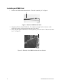
ICMB Card ......................................................................................................................... 73
Installing an ICMB Card ............................................................................................. 74
Removing an ICMB Card ........................................................................................... 75
4 Solving Problems
Boot Issues ........................................................................................................................ 77
Issue 1: My server will not power on ......................................................................... 77
Issue 2: Upon boot, my server starts beeping........................................................... 78
Issue 3: My HDD lights went on, I heard the drives spin up, and my
floppy drive light turned on – but I’m not seeing video ................................. 78
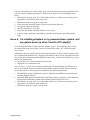
Issue 4: I’m installing adapters in my powered-down system, and my
system boots up when I install a PCI adapter!............................................. 79
Issue 5: My system boots up automatically when I power on my power-strip ........... 80
Issue 6: The boot up process takes too long............................................................. 80
Issue 7: I put one processor in my system but it doesn’t boot................................... 81
Other Issues....................................................................................................................... 82
Issue 8: Some of my hard drives show up during POST and some don’t.................. 82
Issue 9: My hard drives don’t show up under Windows NT....................................... 83
Checking Field Replaceable Units (FRU) with the Diagnostic Wizard................................. 84
Starting the Service Partition & Test Menu ................................................................ 84
Running Tests ........................................................................................................... 85
5 Technical Reference
Connectors......................................................................................................................... 90
Power Distribution Board Interface Connectors (J9B1, J9D1, J9B2).......................... 92
Front Panel Interface (J9E3)...................................................................................... 94
Hot-Plug PCI Indicator Board Interface (J3D1) .......................................................... 96
Memory Module Interface (J6F1)............................................................................... 97
Processor Module Connector (J7A1, J7B1, J7C1, J7D1)........................................... 99
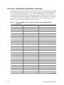
Processor Termination, Regulation, and Power ....................................................... 102
Termination Card ..................................................................................................... 103
Server Monitor Module Connector (J7H1)................................................................ 103
SM Bus Connector (J9E4) ....................................................................................... 104
ICMB Connector (J1D2) .......................................................................................... 105
Auxiliary I2C Connector (J9E4) ................................................................................ 105
Baseboard Fan Connectors (J3C1, J3A1, J4A1, J4C1) ........................................... 105
Internal USB Header (J1B3) .................................................................................... 106
Internal Disk Drive LED Connection......................................................................... 106
Baseboard Jumpers ......................................................................................................... 107
Changing Jumper Settings....................................................................................... 108
CMOS Clear Jumper ............................................................................................... 109
Password Clear Jumper........................................................................................... 110
Recovery Boot Jumper ............................................................................................ 110
Interrupts .......................................................................................................................... 111
Video Modes .................................................................................................................... 112
Contents
v
A Equipment Log and Configuration Worksheets
Equipment Log ........................................................................................................ 113
Configuration Worksheets........................................................................................ 115
Power Configuration Worksheet .............................................................................. 115
SSU Worksheets ..................................................................................................... 115
B Regulatory Specifications
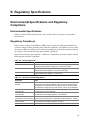
Environmental Specifications and Regulatory Compliance ............................................... 125
Environmental Specifications ................................................................................... 125
Regulatory Compliance............................................................................................ 125
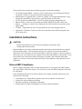
Installation Instructions ..................................................................................................... 126
Ensure EMC Compliance......................................................................................... 126
Ensure Host Computer and Accessory Module Certifications .................................. 127
Prevent Power Supply Overload .............................................................................. 127
Place Battery Marking on Computer ........................................................................ 128
Use Only for Intended Applications.......................................................................... 128
Installation Precautions .................................................................................................... 128
C Warnings
WARNING: English (US) ................................................................................................. 129
AVERTISSEMENT: Français........................................................................................... 129
WARNUNG: Deutsch ...................................................................................................... 129
AVVERTENZE: Italiano ................................................................................................... 130
ADVERTENCIAS: Español.............................................................................................. 130
Index .................................................................................................................................... 131
Figures
1.
2.
3.
4.
5.
6.
7.
8.
9.
10.
11.
12.
13.
14.
Baseboard Connector and Component Locations ..................................................... 14
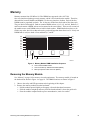
Memory Module DIMM Installation Sequence............................................................ 16
Memory Module DIMM Installation Sequence............................................................ 61
Installing DIMMs: Orientation of DIMM in a Memory Module ..................................... 63
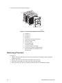
Processor Orientation and Components .................................................................... 64
Installing a VRM ........................................................................................................ 67
Example of a Front Hot-Plug Retention Mechanism .................................................. 69
ICMB Card................................................................................................................. 73
Section of ICMB Internal Cable.................................................................................. 74
Example of an ICMB Card Attached to a Chassis...................................................... 74
Internal Cable Attached to the ICMB Card................................................................. 75
External Cable Attached to the Card ......................................................................... 75
Detailed Diagram of Connector Locations ................................................................. 90
SKA4 Configuration Jumpers................................................................................... 107
Tables
1.
2.
3.
4.
vi
Baseboard Features .................................................................................................. 13
SKA4 Pentium Xeon Processor Family Support Matrix.............................................. 15
Slot State Indicators .................................................................................................. 19
Software Security Features ....................................................................................... 25
SKA4 Baseboard Product Guide
5.
6.
7.
8.
9.
10.
11.
12.
13.
14.
15.
16.
17.
18.
19.
20.
21.
22.
23.
24.
25.
26.
27.
28.
29.
30.
31.
32.
33.
34.
35.
36.
37.
38.
39.
40.
41.
42.
43.
44.
45.
46.
47.
48.
49.
50.
51.
52.
Contents
Configuration Utilities................................................................................................. 27
Hot Keys.................................................................................................................... 28
Main Menu................................................................................................................. 31
Primary IDE Master and Slave Submenu .................................................................. 32
Processor Settings Submenu .................................................................................... 32
Advanced Menu......................................................................................................... 33
Embedded Video Controller Submenu....................................................................... 33
Embedded Legacy SCSI Submenu ........................................................................... 33
Embedded Dual Ultra 160 SCSI Submenu ................................................................ 34
Embedded NIC Submenu.......................................................................................... 34
PCI Device, Slot 1 Submenu ..................................................................................... 34
PCI Device, Slot 2 Submenu ..................................................................................... 35
PCI Device, Slot 3 Submenu ..................................................................................... 35
PCI Device, Slot 4 Submenu ..................................................................................... 35
PCI Device, Slot 5 Submenu ..................................................................................... 36
PCI Device, Slot 6 Submenu ..................................................................................... 36
PCI Device, Slot 7 Submenu ..................................................................................... 36
PCI Device, Slot 8 Submenu ..................................................................................... 37
Hot-Plug PCI Control Submenu ................................................................................. 37
Integrated Peripheral Configuration Submenu ........................................................... 37
Advanced Chipset Control Submenu ......................................................................... 38
Security Menu............................................................................................................ 39
Server Menu.............................................................................................................. 40
System Management Submenu................................................................................. 40
Console Redirection Submenu .................................................................................. 41
EMP Configuration Submenu .................................................................................... 41
PEP Management Submenu ..................................................................................... 42
Boot Menu ................................................................................................................. 42
Boot Device Priority Submenu ................................................................................... 42
Hard Drive Submenu ................................................................................................. 43
Removable Devices Selection Submenu ................................................................... 43
Exit Menu .................................................................................................................. 43
Navigation Keys......................................................................................................... 45
Main Menu................................................................................................................. 46
Exit Menu .................................................................................................................. 46
Main Menu................................................................................................................. 46
Menu for each SCSI Channel .................................................................................... 46
Exit Menu .................................................................................................................. 47
Command Line Format .............................................................................................. 51
VRM/Processor Power Sequence ............................................................................. 66
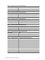
Processor/VRM Population Sequencing .................................................................... 66
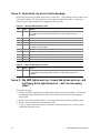
Standard BIOS Port-80 Codes................................................................................... 78
Recovery BIOS Port-80 Codes .................................................................................. 78
Main Power Connector A (J9B1) ............................................................................... 92
Main Power Connector B (J9D1) ............................................................................... 93
Auxiliary Power Connector (J9B2) ............................................................................. 93
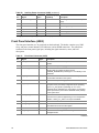
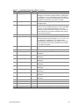
Front Panel Connector (J9E3) ................................................................................... 94
Hot-Plug Indicator Board Connector Pin Out (J3D1).................................................. 96
vii
53.
54.
55.
56.
57.
58.
59.
60.
61.
62.
63.
64.
65.
66.
67.
68.
69.
70.
71.
72.
73.
74.
75.
76.
77.
78.
79.
80.
81.
82.
83.
84.
85.
86.
87.
88.
89.
90.
91.
92.
93.
94.
95.
96.
97.
98.
99.
viii
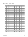
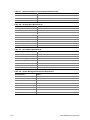
Memory Module Interface .......................................................................................... 97
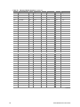
Processor Card Connector Pin Out (J7A1, J7B1, J7C1, J7D1).................................. 99
Processor VRM Connectors (J2A2, J2B1, J2C1): Add-in VRM Connector
Pin Listing.............................................................................................................. 102
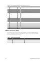
Server Monitor Module Connector Pin Out .............................................................. 103
SM Bus Connector (J9E4) ....................................................................................... 104
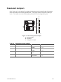
ICMB Connector (J1D2) .......................................................................................... 105
IMB Connector Pin out (J8F1) ................................................................................. 105
Processor Fan Connector #1 (J3C1) ....................................................................... 105
Processor Fan Connector #2 (J3A1) ....................................................................... 106
Processor Fan Connector #3 (J4A1) ....................................................................... 106
Processor Fan Connector #4 (J4C1) ....................................................................... 106
Internal USB Connector (J1B3) ............................................................................... 106
Internal USB Connector (J1B3) ............................................................................... 106
Configuration Jumper Settings................................................................................. 107
Configuration of Jumpers......................................................................................... 108
Beep Codes............................................................................................................. 111
Interrupt Definitions ................................................................................................. 111
Standard VGA Modes.............................................................................................. 112
Equipment Log ........................................................................................................ 113
Devices Worksheet 1............................................................................................... 115
Systems Group Worksheet 2................................................................................... 115
On-board Disk Controllers Worksheet 3 .................................................................. 115
Onboard Communications Devices Worksheet 4..................................................... 116
Diskette Drive Subsystems Group Worksheet 5 ...................................................... 116
IDE Subsystem Group Worksheet 6 ........................................................................ 116
On-Board PCI Devices Group Worksheet 7............................................................. 116
Multiboot Group Worksheet 8 .................................................................................. 117
Security Subsystems Worksheet 9 .......................................................................... 117
Main Menu Worksheet 10........................................................................................ 119
Primary Master and Slave Submenu Worksheet 11 ................................................ 119
Processor Settings Submenu Worksheet 12 ........................................................... 119
Advanced Menu Worksheet 13................................................................................ 119
Embedded Video Controller Submenu Worksheet 14.............................................. 120
Embedded Legacy SCSI Submenu Worksheet 15 .................................................. 120
Embedded Dual Ultra 160 SCSI Submenu Worksheet 16 ....................................... 120
Embedded NIC Submenu Worksheet 17 ................................................................. 120
PCI Device, Slot 1 Submenu Worksheet 18 ............................................................ 120
PCI Device, Slot 2 Submenu Worksheet 19 ............................................................ 120
PCI Device, Slot 3 Submenu Worksheet 20 ............................................................ 120
PCI Device, Slot 4 Submenu Worksheet 21 ............................................................ 120
PCI Device, Slot 5 Submenu Worksheet 22 ............................................................ 121
PCI Device, Slot 6 Submenu Worksheet 23 ............................................................ 121
PCI Device, Slot 7 Submenu Worksheet 24 ............................................................ 121
PCI Device, Slot 8 Submenu Worksheet 25 ............................................................ 121
Hot-Plug PCI Control Submenu Worksheet 26 ........................................................ 121
Integrated Peripheral Configuration Submenu Worksheet 27 .................................. 121
Advanced Chipset Control Submenu Worksheet 28 ................................................ 122
SKA4 Baseboard Product Guide
100.
101.
102.
103.
104.
105.
106.
107.
108.
109.
110.
111.
Contents
Security Menu Worksheet 29................................................................................... 122
Server Menu Worksheet 30 ..................................................................................... 122
System Management Submenu Worksheet 31........................................................ 122
Console Redirection Submenu Worksheet 32 ......................................................... 123
EMP Configuration Submenu Worksheet 33............................................................ 123
PEP Management Submenu Worksheet 34 ............................................................ 123
Boot Menu Worksheet 35 ........................................................................................ 123
Boot Priority Submenu Worksheet 36 ...................................................................... 123
Hard Drive Submenu Worksheet 37 ........................................................................ 123
Removable Devices Selection Submenu Worksheet 38 .......................................... 124
Safety Regulations .................................................................................................. 125
Verification to EMC Regulations .............................................................................. 125
ix
x
SKA4 Baseboard Product Guide
Part I: User’s Guide
1 Baseboard Description
2 Configuration Software and Utilities
11
12
SKA4 Baseboard Product Guide
1 Baseboard Description
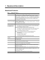
Baseboard Features
Table 1.
Baseboard Features
Feature
Description
Processor
Installed: Up to four Intel® Pentium® III Xeon™ processors, packaged in single
edge contact (S.E.C.) cartridges and installed in 330-pin SC330.1 compliant
edge connectors, operating at 1.8 V to 3.5 V. The baseboard’s voltage regulator
is automatically programmed by the processor’s VID pins to provide the required
voltage. The baseboard includes connectors for three 8.3-compliant plug-in
voltage-regulator modules (VRM).
Single plug-in module containing 64/72-bit four-way-interleaved pathway to main
memory supporting SDRAM.
Installed: 256 MB to 16 GB of error correcting code (ECC) memory. A minimum
of four DIMMs must be installed.
Installed: 2 MB of video memory.
PCI-A—Two full length connectors and one embedded device:
• Two 184-pin, 3.3 V keyed, 64-bit PCI expansion connectors (66/33 MHz).
• One DesotoE2 Hot-Plug PCI controller.
PCI-B—Four full length connectors and two embedded devices:
• One Adaptec† AIC-7899 dual channel SCSI-3 Ultra 160/m SCSI controller.
• Four 184-pin, 5 V keyed, 64-bit PCI expansion connectors (33 MHz).
• One DesotoE2 Hot-Plug PCI controller.
PCI-C—Two half length connectors and several embedded devices:
• Two 120-pin, 32-bit PCI expansion connectors (33 MHz).
• OSB4 I/O APIC.
• PCI network interface controller.
• ATI Rage† IIc video controller.
• PCI narrow/wide Adaptec AIC-7880 Ultra SCSI controller.
The baseboard supports Ultra DMA33 Synchronous Direct Memory Access
(DMA) mode transfers.
The baseboard provides a dual external USB connector and one internally
accessible header.
Thermal/voltage monitoring and error handling.
Front panel controls and indicators (LEDs).
ATI Rage IIc VGA Graphics Accelerator, along with video SGRAM and support
circuitry for an embedded SVGA video subsystem.
Two embedded SCSI controllers:
Adaptec AIC-7899 SCSI Controller—Dual Channel Wide Ultra/Ultra II/Ultra
160/M SCSI controller.
Adaptec AIC-7880 SCSI Controller—PCI narrow/wide Ultra SCSI controller.
PS/2†-compatible keyboard and mouse ports, 6-pin DIN.
Advanced parallel port, supporting Enhanced Parallel Port (EPP) levels 1.7 and
1.9, ECP, compatible 25-pin.
VGA video port, 15-pin.
Two serial ports, 9-pin (serial port A is the top connector).
Form-factor, 16 × 13 inches, ATX-style backpanel I/O.
Memory, dynamic
random access (DRAM)
Video memory (DRAM)
PCI Segment A bus
PCI Segment B bus
PCI Segment C bus
PCI Bus Master IDE
Interface
USB Interface
Server Management
Graphics
SCSI
System I/O
Form Factor
13
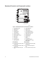
Baseboard Connector and Component Locations
A
B
Z
JJ
C
Y
X
W
V
U
T
AA
S
BB
R
CC
Q
DD
II
J
D
E
HH
F
K
L
M
G
H
O
N
P
EE FF GG I
OM09918
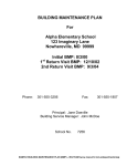
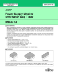
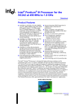
Figure 1. Baseboard Connector and Component Locations
A.
C.
E.
G.
I.
K.
M.
O.
Q.
S.
U.
W.
Y.
Legacy Narrow SCSI
SMM Connector
HDD Activity
ICMB Connector
Lithium Battery
Video Connector
Network Connector
COM1, COM2 Connector
Main Power 1
Main Power 2
Front Panel
Floppy Connector
Ultra 160 SCSI A
AA. Processor #1
CC. Processor #3
EE. Voltage Regulator Module (VRM)
Connector #2
GG. Voltage Regulator Module (VRM)
Connector #4
II. 64-bit, 66/33 MHz Hot-Plug PCI
Slots
14
B.
D.
F.
H.
J.
L.
N.
P.
R.
T.
V.
X.
Z.
Legacy Wide SCSI
IMB Connector
HPIB Connector
Internal USB Connector
Memory Module Connector
USB, External Connector
Parallel Connector
Keyboard/Mouse
Auxiliary Power
SMBus
IDE Connector
Configuration Jumpers
Ultra 160 SCSI BA. Legacy
Narrow SCSI
BB. Processor #2
DD. Processor #4
FF. Voltage Regulator Module (VRM)
Connector #3
HH. 32-bit, 33 MHz Half-length PCI
Slots
JJ. 64-bit, 33 MHz Hot-Plug PCI Slots
SKA4 Baseboard Product Guide
CAUTION
Lithium Battery: See "Replacing the Backup Battery" on page 68 of this
product guide for instructions on replacing and disposing of the Lithium
Battery.
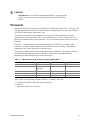
Processor
Each Intel Pentium III Xeon processor is packaged in a single edge contact (S.E.C.) cartridge. The
cartridge includes the processor core with an integrated 32 KB primary (L1) cache, the secondary
(L2) cache, a thermal plate, and a plastic cover.
The processor core and L2 cache components are on a pre-assembled printed circuit board,
approximately 5 inches by 6 inches. The L2 cache and processor core L1 cache interface use a
private bus isolated from the processor host bus. The L2 cache bus operates at the processor core
frequency.
Each S.E.C. cartridge connects to the baseboard through a 330-pin SC330.1 compliant edge
connector. A retention module attached to the baseboard secures the cartridge. Depending on
configuration, the system supports one to four processors.
The processor external interface is MP-ready and operates at 100 MHz. The processor contains a
local Advanced Configuration and Power Interface (APIC) unit for interrupt handling in
multiprocessor (MP) and uniprocessor (UP) environments.
Table 2.
SKA4 Pentium Xeon Processor Family Support Matrix
Name
Frequency
Cache Size
Support (Y/N)
Pentium II Xeon processor
400 MHz, 450 MHz
512k, 1M, 2M
No
Pentium III Xeon processor
500 MHz
512k, 1M, 2M
Yes
550 MHz
Pentium III Xeon processor
600 MHz +
256k
No
2.8 V Pentium III Xeon processor
600 MHz +
1M, 2M
Yes
5/12 V Pentium III Xeon processor
600 MHz +
1M, 2M
No
The L2 cache is located on the substrate of the S.E.C. cartridge. The cache:
•
•
•
Is offered in 512 KB, 1 MB, and 2 MB configurations
Has ECC
Operates at the full core clock rate
Baseboard Description
15
Memory
Main memory resides on an add-in board, called a memory module, designed for the SKA4
baseboard. The memory module contains slots for 16 DIMMs, each of which must be at least
64 MB, and is attached to the baseboard through a 330-pin connector, called the Memory
Expansion Card Connector (MECC). The memory module supports PC-100 compliant registered
ECC SDRAM memory modules. The ECC used for the memory module is capable of correcting
single-bit errors (SBEs) and detecting 100 percent of double-bit errors over one code word. Nibble
error detection is also provided.
System memory begins at address 0 and is continuous (flat addressing) up to the maximum amount
of DRAM installed (exception: system memory is noncontiguous in the ranges defined as memory
holes using configuration registers). The system supports both base (conventional) and extended
memory.
• Base memory is located at addresses 00000h to 9FFFFh (the first 1 MB).
• Extended memory begins at address 0100000h (1 MB) and extends to 3FFFFFFFFh (16 GB),
which is the limit of supported addressable memory. The top of physical memory is a
maximum of 16 GB (to 3FFFFFFFFh).
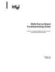
Memory amounts from 256 MB to 16 GB of DIMM are supported, with a 64/72-bit
four-way-interleaved pathway to main memory, which is also located on the module. Therefore,
data transfers between MADPs and DIMMs is in four-way interleave fashion. Each of the four
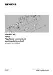
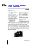
DIMMs must be populated in a bank. The 16 slots are divided into four banks of four slots each.
They are labeled A through D. Bank A contains DIMM sockets A1, A2, A3, and A4. Banks B, C,
and D each contain 4 DIMM sockets and are named in the same fashion. There are silk screens on
the module next to each DIMM socket to label its bank number. For the best thermal results,
populate the banks from A to D. For example, populate bank A and then bank B. For best
performance results, populate adjacent banks. For example, populate bank A and then bank C.
A3
C3
B3
D3
A1
C1
B1
D1
A4
C4
B4
D4
A2
C2
B2
D2
X
Y
Z
OM09919
Figure 2. Memory Module DIMM Installation Sequence
X.
Y.
Z.
16
One of sixteen DIMM sockets
One of four Memory Address Data Paths (MADP)
Memory Expansion Card Connector (MECC)
SKA4 Baseboard Product Guide
Each slot is identified by another notation. Sockets A1 through A4 are identified as J1 through J4
respectively. Sockets B1 through B4 are identified as J5 through J8. Sockets C1 through C4 are
identified as J9 through J12. Sockets D1 through D4 are identified as J13 through J16.
✏
NOTE
Based on the chipset, addressable memory can be extended to 16 GB.
However, some server systems are not thermally configured to support all
16 GB. Consult the documentation accompanying your server system to
determine the maximum memory configuration of your server system.
Some operating systems and application programs use base memory while others use both
conventional and extended memory. Examples are
• Base memory: Microsoft MS-DOS†, IBM OS/2†, Microsoft Windows NT†, and various
UNIX†
• Conventional and extended memory: IBM OS/2, Microsoft Windows NT, and various UNIX
MS-DOS does not use extended memory; however, some MS-DOS utility programs like RAM
disks, disk caches, print spoolers, and windowing environments use extended memory for better
performance.
The BIOS automatically detects, sizes, and initializes the memory array, depending on the type,
size, and speed of the installed DIMMs, and reports memory size and allocation to the system via
configuration registers.
✏
NOTE
DIMM sizes and compatibility: Use DIMMs that have been tested for
compatibility with the baseboard. For a list of approved DIMMs, see the
SKA4 Memory Qualification List. The document can be found on
http://support.intel.com/support/motherboards/server/SKA4/compat.htm.
Baseboard Description
17
Peripherals
Super I/O Chip (SIO)
The National† PC97317VUL Super I/O Plug and Play Compatible with ACPI Compliant
Controller/Extender device supports two serial ports, one parallel port, diskette drive, and
PS/2-compatible keyboard and mouse. The system provides the connector interface for each port.
Serial Ports
Both serial ports can be relocated. Each serial port can be set to one of four different COMx ports,
and each can be enabled separately. When disabled, serial port interrupts are available to add-in
boards.
Parallel Port
The SKA4 baseboard provides a 25-pin Parallel Port connector. The SIO provides an IEEE
1284-compliant 25-pin bi-directional parallel port. BIOS programming of the SIO registers enable
the parallel port, and determine the port address and interrupt. When disabled, the interrupt is
available to add-in cards.
Add-in Board Slots
The baseboard has eight slots for PCI add-in boards supported by three PCI bus segments called
PCI-A, PCI-B, and PCI-C. There are two on PCI-A, four on PCI-B, and two on PCI-C. PCI-C
supports half-length boards (5.6" to 6.3") only; the other slots support full-length boards.
The two slots for the PCI bus segment PCI-C consume a maximum of 375 mA of standby current
on a 3.3V AUX power line. The remaining six slots do not have any 3.3V Aux capabilities.
Both PCI segments A and B allow you to add, remove, or replace PCI add-in boards installed in
their slots without interrupting normal operation or powering down the system. To use this PCI
Hot-Plug (PHP) feature, a server system requires PCI Hot-Plug software and PCI Hot-Plug capable
add-in boards. PCI Hot-Plug software usually is a driver loaded for a specific operating system.
Each Hot-Plug PCI slot has two LEDs. The green LED indicates the state of power on each slot.
The amber LED indicates an error condition with that slot.
18
SKA4 Baseboard Product Guide
The table below summarizes typical LED states that you may encounter during a system’s
operation.
Table 3.
Slot State Indicators
LED State
Status
Green On
Amber Off
The slot is on and functioning normally.
Green On
Amber On
The slot is on and the card requires attention.
Green Off
Amber On
The slot is off and the card in the slot requires attention.
Green blinking
Amber Off
Slot power is transition from either ON to OFF or OFF to ON.
Off
The slot is powered off.
PCI features include:
• 33 or 66 MHz bus speed
• 32-bit or 64-bit memory addressing
• 3.3V or 5V signaling environment
• Independent bus structure supports transfers up to 1.2 GB/sec
• 8-, 16-, 32-, or 64-bit data transfers
• Plug and Play ready
• Parity enabled
DesotoE2 Hot-Plug PCI Controller
The DesotoE2 Hot-Plug PCI controller is a 32-bit PCI bus agent that operates at either 33 or
66 MHz. The PCI controller manages PHP functionality for the PCI segment it resides on. There
is a DesotoE2 controller on PCI segments A and B. The DesotoE2 PHP controller is:
• ACPI compliant
• Compatible with Compaq’s† PHP controller design
• Supports either a 3.3 V or 5 V PCI bus
The DesotoE2 is responsible for:
• Managing power application and removal to individual slots
• Properly resetting newly-added PCI boards prior to bringing the board online
• Managing connection and disconnection of the PCI signals between the P CI bus and the addin board
• Managing seamless addition and removal of individual PCI add-in boards without impacting
bus functionality
IDE Interface
The Open South Bridge (OSB4) acts as a PCI-based fast IDE controller. The controller supports
programmed I/O and bus master transfers. While the OSB4 supports two IDE channels, the SKA4
baseboard uses only the primary IDE channel and provides a single 40 pin IDE connector.
Baseboard Description
19
USB Interface
The SKA4 baseboard provides a dual external USB connector for the back panel of a server
system. The connector is defined by the USB Specification, Revision 1.0. Both ports function
identically with the same bandwidth. The SKA4 baseboard also provides a proprietary internal
USB header.
Network Interface Controller (NIC)
The SKA4 baseboard supports a 10BASE-T/100BASE-TX network subsystem based on the
Intel® 82559 Fast Ethernet Multifunction PCI/CARDBus controller. The Intel 82559 controller is
a highly integrated PCI LAN controller in a 196-pin Ball Grid Array (BGA) supporting 10 or
100 Mbps fast Ethernet networks.
Supported network features include:
• Glueless 32-bit PCI Bus Master Interface compatible with the PCI Local bus Specification
• 82596-like chained memory structure with improved dynamic transmit chaining for enhanced
performance
• Programmable transmit threshold for improved bus utilization
• Early receive interrupt for concurrent processing of receive data
• On-chip counters for network management
• Auto-detect and auto-switching for 10 or 100 Mbps network speeds
• Support for both 10 and 100 Mbps networks
• Integrated physical interface to TX magnetics
• The magnetics component terminates the 100BASE-TX connector interface and a flash device
stores the network ID
Video
The SKA4 baseboard provides an ATI Rage IIc VGA Graphics Accelerator, along with video
Synchronous Graphics RAM (SGRAM) and support circuitry for an embedded Super VGA
(SVGA) video subsystem. The ATI Rage IIc chip contains an SVGA video controller, clock
generator, BitBLT engine, and a RAM digital-to-analog Converter (RAMDAC) in a 208-pin
PQFP. One 256K x 32 SGRAM chip provides 2 MB of 10-ns video memory. The baseboard does
not support adding video memory to the system. The SVGA subsystem supports a variety of
modes, up to 1600 x 1200 resolution, or up to 16.7 M colors.
The SVGA subsystem also supports analog VGA monitors, single- and multi-frequency, interlaced
and non-interlaced, up to 100 Hz vertical retrace frequency. The SKA4 baseboard provides a
standard 15-pin VGA connector and video blanking logic for server management console
redirection support.
Depending on the environment, the controller displays up to 16.7 M colors in some video
resolutions.
20
SKA4 Baseboard Product Guide
SCSI Controller
The baseboard includes two SCSI controllers. A dual function SCSI controller
(Adaptec AIC-7899) is on the PCI-B bus, and a PCI wide SCSI controller (Adaptec AIC-7880) is
on the PCI-C bus.
The Adaptec AIC-7899 SCSI controller contains two independent SCSI controllers that share a
single PCI bus master interface as a multifunction device, packaged in a 352-pin ball grid array
(BGA). Internally, each controller is identical, capable of operations using either 16-bit SE or Low
Voltage Differential (LVD) SCSI providing 40 MBps (Ultra-wide SE), 80 MBps (Ultra 2), or
160 MBps (Ultra 160/m).
In the SKA4 implementation, both controller A and controller B attach to a 68-pin 16-bit
differential SCSI connector LVD interface. Each controller has its own set of PCI configuration
registers and SCSI I/O registers. As a PCI bus master, the AIC-7899 controller supports burst data
transfers on PCI up to the maximum rate of 266 MBps using on-chip buffers.
The AIC-7880 controller contains a single SCSI controller with full-featured PCI bus master
interface in a 160-pin Plastic Quad Flat Pack (PQFP). The controller supports either 8- or 16-bit
Fast SCSI providing 10 MBps or 20 MBps (Fast-10) throughput, or Fast-20 SCSI that can burst
data at 20 MBps or 40 MBps. As a PCI 2.1 bus master, the AIC-7880 controller supports burst
data transfers on PCI up to the maximum rate of 133 MBps using the on-chip 256-byte FIFO.
The SKA4 AIC-7880 implementation offers 8-bit or 16-bit SCSI connectors and operation at data
transfer rates of 10, 20, or 40 MBps. The AIC-7880 controller also offers active negation outputs,
controls for external differential transceivers, a disk activity output, and a SCSI terminator powerdown control. Active negation outputs reduce the chance of data errors by actively driving both
polarities of the SCSI bus, avoiding indeterminate voltage levels and common-mode noise on long
cable runs. The SCSI output drivers can directly drive a 48-mA single-ended SCSI bus with no
additional drivers. The SCSI segment can support up to 15 devices.
The AIC-7880 controller can be used as an 8-bit controller via the narrow, 50-pin connector and as
a 16-bit controller via the wide, 68-pin connector. As a result, the AIC-7880 controller is not
always at one end of the SCSI bus, and termination is controlled through some simple circuitry.
The circuitry senses whether there is a device attached through the narrow 50-pin connector or the
wide 68-pin connector. When there are devices off both connectors, the termination is on for the
upper 8 bits of data and the parity bit associated with these data lines. All other signals are not
terminated on board and are terminated by the devices attached through the connector. When there
is a device on only one connector (either wide or narrow), all on-board termination is on.
Baseboard Description
21
IDE Controller
IDE is a 16-bit interface for intelligent disk drives with AT† disk controller electronics onboard.
The Open South Bridge (OSB4) acts as a PCI-based fast IDE controller. The device controls:
• PIO and IDE DMA/bus master operations
• Mode 4 timings
• Transfer rates up to 33 MB/sec
• Ultra DMA 33 capacity
• Buffering for PCI/IDE burst transfers
• Master/slave IDE mode
• Up to two drives for one IDE channel
✏
NOTE
18-inch maximum length of IDE cable: An IDE signal cable can be
connected up to the IDE connector on the baseboard. However, the
maximum length of the cable is 18 inches. The cable supports up to two
devices, one at the end of the cable and the other six inches from the end.
Keyboard and Mouse
The PS/2-compatible keyboard and mouse connectors are mounted in a single-stacked housing
with the mouse connector over the keyboard. External to the system, they appear as two
connectors.
The user can plug in the keyboard and mouse to either connector before powering up the system.
BIOS detects these and configures the keyboard controller accordingly.
The keyboard controller is functionally compatible with the Intel® 8042A microcontroller. The
system can be locked automatically if no keyboard or mouse activity occurs for a predefined length
of time, if specified through the SSU. Once the inactivity (lockout) timer has expired, the
keyboard and mouse do not respond until the previously stored password is entered.
22
SKA4 Baseboard Product Guide
Server Management
Server management features are implemented using one microcontroller called the Baseboard
Management Controller (BMC).
Baseboard Management Controller (BMC)
The BMC and associated circuitry are powered from 5V_Standby, which remains active when
system power is switched off. The BMC is IPMI 1.0 compliant.
The primary function of the BMC is to autonomously monitor system platform management events
and log their occurrence in the nonvolatile System Event Log (SEL). The BMC is compliant to the
Intelligent Platform Management Interface Specification, Version 1.0. These events include
overtemperature and overvoltage conditions, fan failure, or chassis intrusion. While monitoring,
the BMC maintains the nonvolatile Sensor Data Record Repository (SDRR), from which run-time
information can be retrieved. The BMC provides an interface to SDRR information, so software
running on the server can poll and retrieve the current status of the platform. A shared register
interface is defined for this purpose.
Field service personnel can retrieve SEL contents after system failure for analysis by using system
management tools like Intel® LANDesk® Server Manager, Intel Server Control (ISC), or Direct
Platform control (DPC). Because 5V_Standby provides power the BMC, SEL (and SDRR)
information is also available via the interperipheral management bus (IPMB). During monitoring,
the BMC performs the following functions:
• Baseboard temperature and voltage monitoring
• Processor presence monitoring and FRB control
• Baseboard fan failure detection and indicator control
• SEL interface management
• Sensor Data Record Repository (SDRR) interface management
• SDR/SEL timestamp clock
• Baseboard Field Replaceable Unit (FRU) information interface
• System management watchdog timer
• SMI/NMI Status Monitor
• Front panel NMI handling
• Event receiver
• IPMB Management Controller Initialization Agent
• Secure mode control, front panel lock/unlock initiation, and video blank and diskette write
protect monitoring and control
• ACPI Support
• Direct Platform Control (DPC) support
• Platform Event Paging (PEP) / Platform Event Filtering (PEF)
• Power distribution board monitoring
• Speaker beep capability. When the system is powered up, this capability is used to indicate
conditions such as "empty processor slot"
• Pentium III Xeon processor SEEPROM interface for Processor Information ROM (PIROM)
and Scratch EEPROM access
Baseboard Description
23
•
•
•
•
•
•
Processor temperature monitoring
Hot-Plug PCI slot status reporting
Processor bus speed setting
Chassis fan failure light control
Chassis power fault light control
Chassis power light control
System Security
To help prevent unauthorized entry or use of the system, the system includes a three-position key
lock/switch to permit selected access to drive bays (position is communicated to BMC). The
system also includes server management software that monitors the chassis intrusion switch.
Software Locks via the SSU or BIOS Setup
The SSU provides a number of security features to prevent unauthorized or accidental access to the
system. Once the security measures are enabled, access to the system is allowed only after the user
enters the correct password(s). For example, the SSU allows:
• Enable the keyboard lockout timer so the server requires a password to reactivate the keyboard
and mouse after a specified time-out period of 1 to 120 minutes
• Set and enable administrator and user passwords
• Set secure mode to prevent keyboard or mouse input and to prevent use of the front panel reset
and power switches
• Activate a hot key combination to enter secure mode quickly
• Disable writing to the diskette drive when secure mode is set
Using Passwords
If a user password is set and enabled, but an administrator password is not set, a user password
must be entered to boot the system and run the SSU.
If both a user and administrator password is set:
• Enter either one to boot the server and enable the keyboard and mouse
• Enter the administrator password to access the SSU or BIOS Setup to change the system
configuration
Secure Mode
Configure and enable the secure boot mode by using the SSU. When secure mode is in effect,
• The system can boot and the operating system runs, but the user password must be entered for
a user to use the keyboard or mouse
• The system cannot be turned off or reset from the front panel switches
Secure mode has no effect on functions enabled via the Server Manager Module or power control
via the real-time clock (RTC).
24
SKA4 Baseboard Product Guide
Taking the system out of secure mode does not change the state of system power. That is, if you
press and release the power switch while secure mode is in effect, the system will not power off
when secure mode is later removed. However, if the front panel power switch remains depressed
when secure mode is removed, the system will power off.
Summary of Software Security Features
Table 4 lists the software security features and describes what protection each offers. In general,
to enable or set the features listed here, the SSU must be run and configured with the Security
Menu (described in this manual on page 39.) The table also refers to other SSU menus and to the
Setup utility. For greater detail, see Chapter 2, beginning on page 27.
Table 4.
Software Security Features
Feature
Description
Secure mode
How to enter secure mode:
• Setting and enabling passwords automatically places the system in secure
mode.
• If a hot key combination is set (through the SSU or Setup), the system can be
secured simply by pressing the key combination. This means that the user
does not have to wait for the inactivity time-out period.
When the system is in secure mode:
• The server can boot and run the operating system, but mouse and keyboard
input is not accepted until the user password is entered.
• At boot time, if a CD is detected in the CD-ROM drive or a diskette in drive A,
the system prompts for a password. When the password is entered, the
server boots from CD or diskette and disables the secure mode.
• If there is no CD in the CD-ROM drive or diskette in drive A, the server boots
from drive C and automatically goes into secure mode. All enabled secure
mode features go into effect at boot time.
To leave secure mode, enter the correct password(s).
Disable writing to diskette
In secure mode, the server will not boot from or write to a diskette unless a
password is entered. To set this feature, use the SSU Security Subsystem
Group.
To write protect access to diskette whether the server is in secure mode or not,
use the Setup main menu, Floppy Options, and specify Floppy Access as
read only.
Disable the power and
reset buttons
Power and reset buttons are always disabled when the server is in secure mode.
Set a time out period so
that keyboard and mouse
input are not accepted
Specify and enable an inactivity time out period of from 1 to 120 minutes.
Also, screen can be
blanked, and writes to
diskette can be inhibited
If no keyboard or mouse action occurs for the specified period, attempted
keyboard and mouse input will not be accepted.
The monitor display will go blank, and the diskette drive will be write protected
(if these security features are enabled through Setup or the SSU and using
onboard video).
To resume activity, enter the user password.
continued
Baseboard Description
25
Table 4.
Software Security Features (continued)
Feature
Description
Control access to using
the SSU: set
administrative password
To control access to setting or changing the system configuration, set an
administrative password and enable it through Setup or the SSU.
If both the administrative and user passwords are enabled, either can be used to
boot the server or enable the keyboard and/or mouse, but only the
administrative password will allow Setup and the SSU to be changed.
To disable a password, change it to a blank entry or press CTRL-D in the
Change Password menu of the Administrative Password Option menu found in
the Security Subsystem Group.
If you cannot access Setup or the SSU to clear the password, change the Clear
Password jumper. See "CMOS Clear Jumper" on page 109.
Control access to the
system other than SSU:
set user password
To control access to using the system, set a user password and enable it
through Setup or the SSU.
To disable a password, change it to a blank entry or press CTRL-D in the
Change Password menu of the User Password Option menu found in the
Security Subsystem Group.
If you cannot access Setup or the SSU to clear the password, change the Clear
Password jumper. See "CMOS Clear Jumper" on page 109.
26
Boot without keyboard
The system can boot with or without a keyboard. During POST, before the
system completes the boot sequence, the BIOS automatically detects and tests
the keyboard if it is present and displays a message. There is no entry in the
SSU to enable or disable a keyboard.
Specify the boot
sequence
The sequence specified on the menu in the SSU MultiBoot Group will determine
the boot order. If secure mode is enabled (a user password is set), then the
user is prompted for a password before the server fully boots. If secure mode is
enabled and the “Secure Boot Mode” option is also enabled, the server fully
boots but requires a password before accepting any keyboard or mouse input.
SKA4 Baseboard Product Guide
2 Configuration Software and Utilities
This chapter describes the Power-On Self Test (POST) and system configuration utilities. The
table below briefly describes the utilities.
Table 5.
Configuration Utilities
Utility
Description and brief procedure
Page
BIOS Setup
If the system does not have a diskette drive, or the drive is
disabled or misconfigured, use Setup to enable it.
29
Or, you can move the CMOS jumper on the system board from the
default setting (Protect CMOS memory) to the Clear setting; this
will allow most system configurations to boot. For the procedure to
do this, see “CMOS Clear Jumper” on page 109.
Changing Boot Device
Priority
Use this option to change the boot device priority temporarily or
permanently.
44
SCSISelect Utility
Use to configure the SCSI controllers in the system.
45
Adaptec SCSI Utility
Use to configure or view the settings of the SCSI host adapters
and onboard SCSI devices in the system.
46
Server Setup Utility (SSU)
Use for extended system configuration of onboard resources and
add-in boards, viewing the system event log (SEL), setting boot
device priority, or setting system security options.
47
The SSU can be run from either the configuration software CD or
from a set of bootable diskettes. You can create the diskettes from
the CD.
Information entered via the SSU overrides information entered via
Setup.
Direct Platform Control
(DPC) Console
Use to access and monitor the server remotely.
49
FRUSDR Load Utility
Use to update the Field Replacement Unit (FRU), Sensor Data
Record (SDR), and Desktop Management Interface (DMI) flash
components.
51
BIOS Update Utility
Use to update the BIOS or recover from a corrupted BIOS update.
53
Firmware Update Utility
Use to update BMC flash ROM.
56
27
Hot Keys
Use the keyboard’s numeric pad to enter numbers and symbols.
Table 6.
Hot Keys
To do this:
Press these keys
Clear memory and reload the operating
systemthis is a system reset.
<Ctrl+Alt+Del>
Secure your system immediately.
<Ctrl+Alt>+hot key (Set your hot key combination
with the SSU or Setup.)
Enter the Adaptec SCSI Utility during BIOS POST.
<Ctrl+A>
Enter BIOS Setup during BIOS POST.
F2
Abort memory test during BIOS POST.
ESC (Press while BIOS is updating memory size on
screen.)
Power-On Self Test (POST)
Each time you turn on the system, the BIOS begins execution of the Power-On Self Test (POST).
POST discovers, configures, and tests the processors, memory, keyboard, and most installed
peripheral devices. The length of time needed to test memory depends on the amount of memory
installed. POST is stored in flash memory.
1. Turn on your video monitor and system. After a few seconds, POST begins to run and a splash
screen is displayed.
2. While the splash screen is displayed, you can either
• press <F2> to enter the BIOS Setup (see "Using BIOS Setup" on page 29)
OR
•
press <Esc> to change the boot device priority for this boot only (see "Changing the Boot
Device Priority Temporarily" on page 44).
3. After pressing <F2> or <Esc> during POST, you can press <Ctrl+A> to run the SCSISelect
Utility. For more information, see "Running the SCSISelect Utility" on page 45.
4. If you do not press <F2> or <Esc> and do NOT have a device with an operating system
loaded, the boot process continues and the system beeps once. The following message is
displayed:
Operating System not found
5. At this time, pressing any key causes the system to attempt a reboot. The system searches all
removable devices in the order defined by the boot priority.
6. If you want to boot from a hard drive loaded with an operating system, make sure that the hard
drive is installed and push the Reset button on the front panel.
28
SKA4 Baseboard Product Guide
Using BIOS Setup
This section describes the BIOS Setup options. Use Setup to change the system configuration
defaults. You can run Setup with or without an operating system being present. Setup stores most
of the configuration values in battery-backed CMOS; the rest of the values are stored in flash
memory. The values take effect when the system is booted. POST uses these values to configure
the hardware; if the values and the actual hardware do not agree, POST generates an error
message. You must run Setup to specify the correct configuration.
Run Setup: Run Setup to modify any standard PC-AT† baseboard feature such as:
•
•
•
•
•
•
•
Select diskette drive
Select parallel port
Select serial port
Set time/date (to be stored in RTC)
Configure hard drive(s)
Specify boot device sequence
Enable SCSI BIOS
Run SSU, not Setup: Run the SSU instead of Setup to do the following:
•
•
Enter or change information about a board
Alter system resources (e.g., interrupts, memory addresses, I/O assignments) to user-selected
choices instead of choices selected by the BIOS resource manager
Record Setup Settings
If the default values ever need to be restored (after a CMOS clear, for example), Setup must be run
again. Referring to the worksheets could make the task easier.
If Setup is Not Accessible
If the diskette drive is misconfigured and you cannot use Setup to correct the problem, you might
need to clear CMOS memory. You must open the system, change a jumper setting, use Setup to
check and set diskette drive options, and change the jumper back. For a step-by-step procedure,
see “CMOS Clear Jumper” on page 109.
Starting Setup
Setup can be entered under several conditions:
•
•
•
When you turn on the system, after POST completes the memory test.
When you reboot the system by pressing <Ctrl+Alt+Del> while at the DOS operating system
prompt.
When you have moved the CMOS jumper on the baseboard to the “Clear CMOS” position
(enabled); for a step-by-step procedure, see “CMOS Clear Jumper” on page 109.
In the three conditions listed above, the following prompt is displayed:
Press <F2> to enter SETUP
Configuration Software and Utilities
29
In a fourth condition, when CMOS/NVRAM has been corrupted, these other prompts are
displayed, but not the <F2> prompt:
Warning:
cmos checksum invalid
Warning:
cmos time and date not set
In this condition, the BIOS loads default values for CMOS and attempts to boot.
Setup Menus
Setup has six major menus and several submenus:
1. Main Menu
• Primary IDE Master and Slave Adapters
• Processor Settings Information
2. Advanced Menu
•
PCI Configuration
Embedded Video Controller
Embedded Legacy SCSI
Embedded Dual Ultra 160 SCSI
Embedded NIC
PCI Devices, Slots 1 - 8
Hot-Plug PCI Control
• Integrated Peripheral Configuration
• Advanced Chipset Control
3. Security Menu
• Passwords
• Lockout features
4. Server Menu
• System Management
• Console Redirection
• EMP Configuration
• PEP Management
5. Boot Menu
• Boot Device Priority
• Hard Drive
• Removable Devices Selections
6. Exit Menu
30
SKA4 Baseboard Product Guide
Navigation
To:
Press:
Get general help
Move between menus
Go to the previous item
Go to the next Item
Change the value of an item
Select an item or display a submenu
Leave a submenu or exit Setup
Reset to Setup defaults
Save and exit Setup
<F1> or <Alt+H>
←→
↑
↓
+ or <Enter>
<Esc>
<F9>
<F10>
Display
When you see this:
What it means:
On screen, an option is shown but you cannot
select it or move to that field.
You cannot change or configure the option in that
menu screen for one of the following reasons:
• The option is auto-configured or auto-detected.
• You must use a different Setup screen to change it.
• You must use the SSU.
Press <Enter> to display a submenu that is either a
separate full-screen menu or a pop-up menu with one
or more choices.
On screen, the phrase Press Enter appears next
to the option.
The rest of this section lists the features that display onscreen after you press <F2> to enter Setup.
Not all of the option choices are described, because (1) a few are not user-selectable but are
displayed for your information, and (2) many of the choices are relatively self-explanatory.
Main Menu
Table 7 lists the selections you can make on the Main Menu itself. Use the submenus for other
selections. Default values are in bold.
Table 7.
Main Menu
Feature
Choices
Description
System Time
System Date
Legacy Diskette A:
HH:MM:SS
MM/DD/YYYY
Disabled
1.44/1.25 MB 3½"
2.88 MB 3½"
Disabled
1.44/1.25 MB 3½"
2.88 MB 3½"
N/A
N/A
N/A
English (US)
French
Spanish
German
Italian
Japanese (Kanji)
Sets the system time.
Sets the system date.
Selects the diskette type.
Legacy Diskette B:
Primary IDE Master
Primary IDE Slave
Processor Settings
Language
Configuration Software and Utilities
Selects the diskette type.
Enters submenu.
Enters submenu.
Enters submenu.
Selects which language BIOS displays.
✏
NOTE
Serial redirection does
not work with Kanji.
31
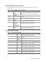
Primary IDE Master and Slave Submenu
In the following table, the features other than “Type” appear only for Type Auto if a drive is
detected.
Table 8.
Primary IDE Master and Slave Submenu
Feature
Choices
Description
Type
User
Auto
CD-ROM
ATAPI Removable
User allows the manual entry of all fields described below.
Auto allows the system to attempt auto-detection of the drive
type.
CD-ROM allows the manual entry of fields described below.
Multi-Sector
Transfers
Disabled
2, 4, 8, or 16 sectors
Determines the number of sectors per block for multisector
transfers.
For Type Auto, this field is informational only.
LBA Mode
Control
Disabled
Enabled
For Type Auto, this field is informational only.
32 Bit I/O
Disabled
Enabled
Enabling allows 32-bit IDE data transfers.
For Type Auto, this field is informational only.
Transfer Mode
Standard
Fast PIO 1
Fast PIO 2
Fast PIO 3/DMA 1
Fast PIO 4/DMA 2
Selects the method for moving data to and from the drive.
For Type Auto, this field is informational only.
Ultra DMA Mode
Disabled
Enabled
For use with Ultra DMA drives. Ultra DMA is disabled by
default to work around a chipset erratum.
For Type Auto, this field is informational only.
Processor Settings Submenu
Table 9.
32
Processor Settings Submenu
Feature
Choices
Description
Processor Retest
No
Yes
Select yes for the BIOS to clear historical processor status
and retest all processors on the next boot.
Processor Serial Number
Enabled
Disabled
If enabled, the system records the serial number of each
processor.
Memory Cache
Enabled
Disabled
Controls cacheability. For debug purposes only.
Measured Processor Speed
N/A
Reports the speed of Processor 1.
Processor 1 CPU ID
N/A
Reports Stepping for Processor 1.
Processor 1 L2 Cache Size
N/A
Reports L2 Cache Size for Processor 1. This feature is
hidden if processor 1 is absent or disabled.
Processor 2 CPU ID
N/A
Reports Stepping for Processor 2.
Processor 2 L2 Cache Size
N/A
Reports L2 Cache Size for Processor 2. This feature is
hidden if processor 2 is absent or disabled.
Processor 3 CPU ID
N/A
Reports Stepping for Processor 3.
Processor 3 L2 Cache Size
N/A
Reports L2 Cache Size for Processor 3. This feature is
hidden if processor 3 is absent or disabled.
Processor 4 CPU ID
N/A
Reports Stepping for Processor 4.
Processor 4 L2 Cache Size
N/A
Reports L2 Cache Size for Processor 4. This feature is
hidden if processor 4 is absent or disabled.
SKA4 Baseboard Product Guide
Advanced Menu
You can make the following selections on the Advanced Menu itself. Use the submenus for the
three other selections that appear on the Advanced Menu.
Table 10.
Advanced Menu
Feature
Choices
Description
PCI Configuration
N/A
Enters submenu.
Integrated Peripheral
Configuration
N/A
Enters submenu.
Advanced Chipset Control
N/A
Enters submenu.
Reset Configuration Data
No
Yes
Select Yes to clear the system configuration data during
next boot. System automatically resets to No in next boot.
Enable Sleep Button
Yes
No
If Yes, the ACPI sleep button is activated.
System Wakeup Feature
Enabled
Disabled
If enabled, the system will be powered up upon receiving a
LAN wakeup event, ring on COM1/COM2, or PME interrupt
from a PCI board.
Delay on Option ROMs
Enabled
Disabled
Enables a short delay after an Option ROM scan.
PCI Configuration Submenu
The PCI Configuration submenu contains selections that access other submenus.
Embedded Video Controller Submenu
Table 11.
Embedded Video Controller Submenu
Feature
Choices
Description
Embedded Video
Controller
Enabled
Disabled
Enables the embedded video controller.
Embedded Legacy SCSI Submenu
Table 12.
Embedded Legacy SCSI Submenu
Feature
Choices
Description
Embedded Legacy
SCSI
Enabled
Disabled
Enables or disables embedded legacy SCSI controller
hardware.
Option ROM Scan
Enabled
Disabled
Initializes the device expansion ROM on the device.
Latency Timer
Default
020h
040h
060h
080h
0A0h
0C0h
0E0h
Minimum guaranteed time, in units of PCI bus clocks, that a
device can be master on a PCI bus. Typically, option ROM
code overwrites the value set by the BIOS.
Configuration Software and Utilities
33
Embedded Dual Ultra 160 SCSI Submenu
Table 13.
Embedded Dual Ultra 160 SCSI Submenu
Feature
Choices
Description
Embedded Legacy
SCSI
Enabled
Disabled
Enables or disables embedded legacy SCSI controller
hardware.
Option ROM Scan
Enabled
Disabled
Initializes the device expansion ROM on the device.
Latency Timer
Default
020h
040h
060h
080h
0A0h
0C0h
0E0h
Minimum guaranteed time, in units of PCI bus clocks, that a
device can be master on a PCI bus. Typically, option ROM
code overwrites the value set by the BIOS.
Embedded NIC Submenu
Table 14.
Embedded NIC Submenu
Feature
Choices
Description
Embedded NIC
Enabled
Disabled
If enabled, the system uses the embedded NIC.
PCI Device, Slot 1
Table 15.
34
PCI Device, Slot 1 Submenu
Feature
Choices
Description
Option ROM Scan
Enabled
Disabled
Initializes device expansion ROM.
Enable Master
Enabled
Disabled
Enables the selected device as a PCI bus master.
Latency Timer
Default
020h
040h
060h
080h
0A0h
0C0h
0E0h
Minimum guaranteed time, in units of PCI bus clocks, that a
device can be master on a PCI bus. Typically, option ROM
code overwrites the value set by the BIOS.
SKA4 Baseboard Product Guide
PCI Device, Slot 2
Table 16.
PCI Device, Slot 2 Submenu
Feature
Choices
Description
Option ROM Scan
Enabled
Disabled
Initializes device expansion ROM.
Enable Master
Enabled
Disabled
Enables the selected device as a PCI bus master.
Latency Timer
Default
020h
040h
060h
080h
0A0h
0C0h
0E0h
Minimum guaranteed time, in units of PCI bus clocks, that a
device can be master on a PCI bus. Typically, option ROM
code overwrites the value set by the BIOS.
PCI Device, Slot 3
Table 17.
PCI Device, Slot 3 Submenu
Feature
Choices
Description
Option ROM Scan
Enabled
Disabled
Initializes device expansion ROM.
Enable Master
Enabled
Disabled
Enables the selected device as a PCI bus master.
Latency Timer
Default
020h
040h
060h
080h
0A0h
0C0h
0E0h
Minimum guaranteed time, in units of PCI bus clocks, that a
device can be master on a PCI bus. Typically, option ROM
code overwrites the value set by the BIOS.
PCI Device, Slot 4
Table 18.
PCI Device, Slot 4 Submenu
Feature
Choices
Description
Option ROM Scan
Enabled
Disabled
Initializes device expansion ROM.
Enable Master
Enabled
Disabled
Enables the selected device as a PCI bus master.
Latency Timer
Default
020h
040h
060h
080h
0A0h
0C0h
0E0h
Minimum guaranteed time, in units of PCI bus clocks, that a
device can be master on a PCI bus. Typically, option ROM
code overwrites the value set by the BIOS.
Configuration Software and Utilities
35
PCI Device, Slot 5
Table 19.
PCI Device, Slot 5 Submenu
Feature
Choices
Description
Option ROM Scan
Enabled
Disabled
Initializes device expansion ROM.
Enable Master
Enabled
Disabled
Enables the selected device as a PCI bus master.
Latency Timer
Default
020h
040h
060h
080h
0A0h
0C0h
0E0h
Minimum guaranteed time, in units of PCI bus clocks, that a
device can be master on a PCI bus. Typically, option ROM
code overwrites the value set by the BIOS.
PCI Device, Slot 6
Table 20.
PCI Device, Slot 6 Submenu
Feature
Choices
Description
Option ROM Scan
Enabled
Disabled
Initializes device expansion ROM.
Enable Master
Enabled
Disabled
Enables the selected device as a PCI bus master.
Latency Timer
Default
020h
040h
060h
080h
0A0h
0C0h
0E0h
Minimum guaranteed time, in units of PCI bus clocks, that a
device can be master on a PCI bus. Typically, option ROM
code overwrites the value set by the BIOS.
PCI Device, Slot 7
Table 21.
36
PCI Device, Slot 7 Submenu
Feature
Choices
Description
Option ROM Scan
Enabled
Disabled
Initializes device expansion ROM.
Enable Master
Enabled
Disabled
Enables the selected device as a PCI bus master.
Latency Timer
Default
020h
040h
060h
080h
0A0h
0C0h
0E0h
Minimum guaranteed time, in units of PCI bus clocks, that a
device can be master on a PCI bus. Typically, option ROM
code overwrites the value set by the BIOS.
SKA4 Baseboard Product Guide
PCI Device, Slot 8
Table 22.
PCI Device, Slot 8 Submenu
Feature
Choices
Description
Option ROM Scan
Enabled
Disabled
Initializes device expansion ROM.
Enable Master
Enabled
Disabled
Enables the selected device as a PCI bus master.
Latency Timer
Default
020h
040h
060h
080h
0A0h
0C0h
0E0h
Minimum guaranteed time, in units of PCI bus clocks, that a
device can be master on a PCI bus. Typically, option ROM
code overwrites the value set by the BIOS.
Hot-Plug PCI Control Submenu
Table 23.
Hot-Plug PCI Control Submenu
Feature
Choices
Description
Hot-Plug PCI BIOS
Support
Enabled
Disabled
If enabled, the system uses resource padding and the HotPlug resource table.
Resource Padding
Level
Disabled
Minimum
Maximum
Determines amount of resources used by each Hot-Plug
PCI slot.
Empty Bus Default
Speed
33 MHtz
66 MHtz
Unoccupied bus default speed.
Integrated Peripheral Configuration Submenu
Table 24.
Integrated Peripheral Configuration Submenu
Feature
Choices
Description
COM1:
Disabled
Enabled
Auto
OS Controlled
If set to "Auto", BIOS configures the port.
If set to "OS Controlled", the OS configures the port.
Base I/O Address
3F8h
2F8h
3E8h
2E8h
Selects the base I/O address for COM port A.
Interrupt
IRQ 4
IRQ 3
Selects the IRQ for COM port A.
COM2:
Disabled
Enabled
Auto
OS Controlled
If set to "Auto", BIOS configures the port.
If set to "OS Controlled", the OS configures the port.
continued
Configuration Software and Utilities
37
Table 24.
Integrated Peripheral Configuration Submenu (continued)
Feature
Choices
Description
Base I/O Address
3F8h
2F8h
3E8h
2E8h
Selects the base I/O address for COM port B.
Interrupt
IRQ 4
IRQ 3
Selects the interrupt for COM port B.
Parallel Port
Disabled
Enabled
Auto
OS Controlled
If set to "Auto", BIOS configures the port.
If set to "OS Controlled", the OS configures the port.
Mode
Output only
Bi-Directional
EPP
ECP
Selects mode for parallel port.
Base I/O Address
378
278
Selects the base I/O address for parallel port.
Interrupt
IRQ 5
IRQ 7
Selects the interrupt for parallel port.
DMA Channel
DMA 1
DMA 3
Selects the DMA channel for parallel port.
Floppy Disk Controller
Enabled
Disabled
If enabled, the system enables the floppy disk
controller.
Advanced Chipset Control Submenu
Table 25.
38
Advanced Chipset Control Submenu
Feature
Option
Description
Base RAM Step
1 MB
1 KB
Every location
Selects the size of step to use during Base RAM tests.
Extended RAM Step
1 MB
1 KB
Every location
No Memory Test
Selects the size of the step to use during Extended
RAM tests.
Remap Memory
Enable
Disable
Enables or disables remapping some amount of
memory lost to PCI devices. This is an advanced
feature. Consult the technical product specification
before changing this option.
SKA4 Baseboard Product Guide
Security Menu
You can make the following selections on the Security Menu. Enabling the Supervisor Password
field requires a password for entering Setup. The passwords are not case sensitive.
Table 26.
Security Menu
Feature
Choices
Description
User Password is
Clear
Set
Administrator Password is
Clear
Set
Set User Password
Press Enter
Set Administrative Password
Press Enter
Password on Boot
Disabled
Enabled
Normal
Write Protect
Disabled
1, 2, 5, 10,
or 20 min
1 or 2 hr
[]
[A, B, ..., Z]
[0-9]
Status only; user cannot modify. Once set, this can be
disabled by setting it to a null string or by clearing password
jumper on baseboard (see “Password Clear Jumper,”
page 110).
Status only; user cannot modify. Once set, this can be
disabled by setting it to a null string or by clearing
password jumper on baseboard (see “Password Clear
Jumper” page 110).
When the <Enter> key is pressed, the user is prompted for a
password; press ESC key to abort. Once set, this can be
disabled by setting it to a null string or by clearing password
jumper on baseboard (see “Password Clear Jumper”
page 110).
When the <Enter> key is pressed, the user is prompted for a
password; press ESC key to abort. Once set, this can be
disabled by setting it to a null string or by clearing password
jumper on baseboard (see “Password Clear Jumper”
page 110).
If enabled and the user password is set, the system
prompts the user for a password before the system boots.
Write-protects boot sector on hard disk to protect against
viruses.
Period of keyboard or PS/2 mouse inactivity specified for
secure mode to activate. A password is required for
secure mode to function. Cannot be enabled unless at
least one password is enabled.
Key assigned to invoke the secure mode feature. Cannot
be enabled unless at least one password is enabled. Can
be disabled by entering a new key followed by a
backspace or by entering <Delete>.
System boots in secure mode. The user must enter a
password to unlock the system. Cannot be enabled unless
at least one password is enabled.
Blank video when secure mode is activated. The user
must enter a password to unlock the system. Cannot be
enabled unless at least one password is enabled.
When secure mode is activated, the diskette drive is write
protected. The user must enter a password to re-enable
diskette writes. Cannot be enabled unless at least one
password is enabled.
Fixed Disk Boot Sector
Secure Mode Timer
Secure Mode Hot Key
(Ctrl-Alt- )
Secure Mode Boot
Disabled
Enabled
Video Blanking
Disabled
Enabled
Floppy Write Protect
Disabled
Enabled
Configuration Software and Utilities
39
Server Menu
Table 27.
Server Menu
Feature
Choices
Description
System Management
N/A
Enters submenu.
Console Redirection
N/A
Enters submenu.
EMP Configuration
N/A
Enters submenu.
PEP Management
N/A
Enters submenu.
Service Boot
Enable
Disable
Service Partition Type
[0-999]
System Event Logging
Disabled
Enabled
Enabled forces BIOS and BMC to log system events.
Clear Event Log
No
Yes
If Yes, the System Event log is cleared.
Assert NMI on PERR
Disabled
Enabled
If enabled, PCI bus parity error (PERR) is enabled and is
routed to NMI.
Assert NMI on SERR
Disabled
Enabled
If enabled, PCI bus system error (SERR) is enabled and
is routed to NMI.
FRB-2 CPU Policy
Disable BSP
Do not disable
BSP
What action to take when FRB-2 occurs.
System Management Submenu
Table 28.
40
System Management Submenu
Feature
Choices
Description
Board Part Number
N/A
Information field only
Board Serial Number
N/A
Information field only
System Part Number
N/A
Information field only
System Serial Number
N/A
Information field only
Chassis Part Number
N/A
Information field only
Chassis Serial Number
N/A
Information field only
BMC Revision
N/A
Information field only
Primary HSBP Revision
N/A
Information field only
SKA4 Baseboard Product Guide
Console Redirection Submenu
Table 29.
Console Redirection Submenu
Feature
Choices
Description
COM Port Address:
Redirection
disabled
Disabled
3F8
2F8
3E8
3 or 4
When enabled, Console Redirection uses the I/O port specified.
When disabled, Console Redirection is completely disabled.
IRQ #
Baud Rate
9600
19.2k
38.4k
115.2k
Flow Control
No flow control
CTS/RTS
XON/XOFF
CTS/RTS + CD
When Console Redirection is enabled, this displays the IRQ
assigned per the address chosen in the COM Port Address field.
When Console Redirection is enabled, use the baud rate
specified.
When the Direct Platform Control (DPC) shares the COM port as
console redirection, the baud rate must be set to 19.2k to match
DPC baud rate, unless the autobaud feature is used.
None disallows flow control.
CTS/RTS is hardware based flow control.
XON/XOFF is software flow control.
CTS/RTS +CD is hardware based plus carrier-detect flow control.
When DPC is sharing the Comm port as Console Redirection, the
flow control must be set to XON/XOFF or XON/XOFF+CD
depending on whether a modem is used.
EMP Configuration Submenu
Table 30.
EMP Configuration Submenu
Feature
Choices
Description
EMP Password
Switch
Disabled
Enabled
Enabled/Disables EMP password.
EMP ESC
Sequence
EMP Hang-up Line
String
Modem Init String
+++ or other
text
ATH or other
text
ATE1Q0V1X4&
D0S0=0 or
other text
Pre-Boot Only
Always
Active
Disabled
Disabled
Enabled
Direct Connect
Modem Mode
Escape string for the modem EMP port.
[Phone number]
Phone number of system you are dialing into.
EMP Access Mode
EMP Restricted
Mode Access
EMP Direct
Connect/Modem
Mode
System Phone
Number
Configuration Software and Utilities
Hang-up string for the modem EMP port.
20 characters to set up the modem.
Establishes EMP access mode.
Enables/Disables EMP Restricted Mode Access.
Establishes connection for EMP port.
41
PEP Management Submenu
Table 31.
PEP Management Submenu
Feature
Choices
Description
PEP Filter Events
N/A
Enters Submenu with a single feature listed. If the feature is
enabled, all triggers for PEP are enabled.
PEP Enable
Enable
Disable
Enables PEP.
PEP Blackout
Period
[0 – 255]
Time in minutes between consecutive pages. Entering 0
disables paging.
PEP Page String
[Phone number]
Send Test Page
<Enter>
Press <Enter> to send a test page.
Boot Menu
You can make the following selections on the Boot Menu itself.
Table 32.
Boot Menu
Feature
Choices
Description
Boot-Time Diagnostic Screen
Disabled
Enabled
If Enabled, system displays the diagnostic screen
during the boot process.
Boot Device Priority
N/A
Enters submenu.
Hard Drive
N/A
Enters submenu.
Removable Devices
N/A
Enters submenu.
Maximum number of I2O Drives
1
4
Selects the maximum number of I2O drives assigned
a DOS drive letter.
Boot Device Priority Submenu
Use the up- or down-arrow keys to select a device. Press the <+> or <-> keys to move the device
higher or lower in the boot priority list.
Table 33.
42
Boot Device Priority Submenu
Boot Priority
Device
Description
1.
Removable Devices
Attempts to boot from a removable media device.
2.
Hard Drive
Attempts to boot from a hard drive device.
3.
ATAPI CD-ROM Drive
Attempts to boot from an ATAPI CD-ROM drive.
4.
Intel UND1, PXE-2.0
Wired for Management WFM 2.0 Specification.
SKA4 Baseboard Product Guide
Hard Drive Submenu
For options on this menu, use the up or down arrow keys to select a device. Press the <+> or <->
keys to move the device higher or lower in the boot priority list.
Table 34.
Hard Drive Submenu
Option
Description
1. Drive #1 (or actual drive string)
Other bootable cards cover all the boot devices that are not
reported to the system BIOS through BIOS Boot Specification
mechanisms. It may or may not be bootable, and may not
correspond to any device.
2. Other bootable cards
(additional entries for each drive that
has a PnP header)
Removable Devices Selection Submenu
For options on this menu, use the up or down arrow keys to select a device.
Table 35.
Removable Devices Selection Submenu
Feature
Option
Description
Lists Bootable Removable devices in
the system.
+/-
This list includes legacy 1.44 MB floppy drives and
120 MB floppy drives.
Exit Menu
You can make the following selections on the Exit Menu. Select an option using the up or down
arrow keys. Press <Enter> to run the option. Pressing <Esc> does not exit this menu. You must
select one of the items from the menu or menu bar to exit.
Table 36.
Exit Menu
Choices
Description
Exit Saving Changes
Exits and saves changes to CMOS.
Exit Discarding Changes
Exits without saving changes to CMOS. User is prompted if any of
the Setup fields were modified.
Load Setup Defaults
Loads default values for all Setup data.
Save Custom Defaults
Loads settings from custom defaults.
Discard Changes
Reads previous values of all Setup data from CMOS.
Save Changes
Saves Setup data to CMOS.
Configuration Software and Utilities
43
Changing the Boot Device Priority Temporarily
During POST, you can change the boot device priority for the current boot process. The changes
made during this instruction set are not retained for the next boot process.
1. Boot the server.
2. At any time during POST, press <Esc>. When POST completes, a pop-up Boot menu is
displayed.
3. Use the arrow keys to highlight the device you want the server system to boot from first. For
example, if you want the server system to boot from the CD-ROM first, you select "CD-ROM
Drive."
✏
NOTE
One of the selections on the pop-up Boot menu is "Enter Setup". Selecting
this option brings you into the BIOS setup. For more information about the
BIOS setup, see "Using BIOS Setup" on page 29.
4. Press <Enter>.
5. The bootup process continues. When finished, a system prompt is displayed.
Changing the Boot Device Priority Permanently
You can change the boot device permanently. Until you change the boot device priority again via
this instruction set, the boot device priority does not change.
1. Quickly press the <F2> key. A prompt may or may not appear. After a few bootup tests
complete, the main BIOS Setup screen appears.
2. From the Setup screen, select Boot Menu. Press <Enter>.
3. Select Boot Device Priority, and press <Enter>.
4. In the Boot Device Priority screen, use the up- or down-arrow keys to select "ATAPI
CD-ROM Drive", or the appropriate SCSI CD-ROM drive, then press the <+> key to move it
to the top of the list.
5. Now set the second boot device to Diskette Drive and the third boot device to Hard Drive.
6. Press the <F10> key to save your changes and exit Setup.
7. When the Exit prompt appears, press <Enter> again.
8. The bootup process continues. When finished, an operating system prompt is displayed.
9. Make sure the CD is in the drive, and boot the server.
44
SKA4 Baseboard Product Guide
Running the SCSISelect Utility
Each host adapter includes an onboard SCSISelect configuration utility that allows you to
configure/view the settings of the host adapters and devices in the server.
After pressing <F2> or <Esc> during POST, the splash screen is replaced by text.
The system first finds the Adaptec AIC-7880 SCSI host adapter and displays the message
Adaptec AIC-7880 SCSI BIOS V x.xxx where x.xxx is the version number of the SCSISelect
utility. Pressing <Ctrl+A> at this time allows you to configure the Adaptec AIC-7880 SCSI host
adapter.
If you do not press <Ctrl+A>, the system finds the Adaptec AIC-7899 SCSI host adapter and
displays the message Adaptec AIC-7899 SCSI BIOS V x.xxx where x.xxx is the version number
of the SCSISelect utility. Pressing <Ctrl+A> at this time allows you to configure the Adaptec
AIC-7899 SCSI host adapter.
Once you enter the configuration menus for one of the host adapters, you cannot switch to the
other adapter. For example, once you press <Ctrl+A> to configure the Adaptec AIC-7899 SCSI
host adapter, you have to reboot the system to configure the Adaptec AIC-7880 SCSI host adapter.
When to Run the SCSISelect Utility
Use the SCSISelect utility to
•
•
•
change default values
check and/or change SCSI device settings that may conflict with those of other devices in the
server
do a low-level format on SCSI devices installed in the server
Running the SCSISelect Utility
1. When this message appears on the video monitor:
<<<Press <Ctrl><A> for SCSISelect(TM) Utility!>>>
2. Press <Ctrl+A> to run the utility. When the main menu for the host adapter appears, choose
the adapter that you want to configure—each SCSI bus accepts up to 15 devices.
Use the following keys to navigate through the menus and submenus.
Table 37.
Press
Navigation Keys
To
ESC
Exit the utility
Enter
Select an option
↑
Return to a previous option
↓
Move to the next option
F5
Switch between color and monochrome
F6
Reset to host adapter defaults
Configuration Software and Utilities
45
Configuring the Adaptec AIC-7880 SCSI Adapter
The following menu is displayed when you configure the Adaptec AIC-7880 SCSI adapter.
Table 38.
Main Menu
Host Adapter
Option
Comment
AIC-7880 Ultra/Ultra W
at Bus:Device 00:01h
Configure/View Host
Adapter Settings
Press <Enter> to view the Configuration Menu.
SCSI Disk Utilities
Press <Enter> to view the SCSI Disk Utilities Menu.
Make a selection and press <Enter>.
When you are finished, press <Esc> and make your selection from the following menu.
Table 39.
Exit Menu
Feature
Option
Comment
Exit Utility?
Yes
No
When you finish configuring your SCSI devices, select Yes and press <Enter>.
When this message appears:
Please press any key to reboot
Press any key, and your server will reboot.
Configuring the Adaptec AIC-7899 SCSI Adapter
The Adaptec AIC-7880 SCSI adapter has two busses. Select the bus from the following menu.
Table 40.
Main Menu
Menu Item
Options
You have an AIC-7899 adapter in your system. Move
the cursor to the bus:device:channel of the one to be
configured and press <Enter>.
Bus:Device:Channel
01:06:A
01:06:B
<F5> - Toggle color/monochrome
After selecting the bus, the following menu is displayed.
Table 41.
46
Menu for each SCSI Channel
Host Adapter
Option
Comment
AIC-7899 at
Bus:Device:Channel
01:06:A (or 01:06:B)
Configure/View Host
Adapter Settings
Press <Enter> to view the Configuration Menu.
SCSI Disk Utilities
Press <Enter> to view the SCSI Disk Utilities
Menu. This menu allows you to format hard
disks and/or verify disk media.
SKA4 Baseboard Product Guide
When you are finished, press <Esc> and make your selection from the following menu.
Table 42.
Exit Menu
Feature
Option
Comment
Exit Utility?
Yes
No
When you finish configuring your SCSI devices, press <Esc>. Then select Yes
and press <Enter>. When this message appears:
Please press any key to reboot
Press any key, and the server reboots.
Using the System Setup Utility (SSU)
The SSU is on the configuration software CD shipped with the server. The SSU provides a
graphical user interface (GUI) over an extensible framework for server configuration. The
SSU framework supports the following functions and capabilities:
• Assigns resources to baseboard devices and add-in boards before loading the operating system
• Specifies the boot device order and system security options
• Permits viewing and clearing of the system event log (SEL)
• Permits viewing of the system FRU and SDRs
• Allows troubleshooting of the server when the operating system is not operational
• Provides a system-level view of the server’s I/O devices
When to Run the SSU
The SSU is a DOS-based utility that supports extended system configuration operations for
onboard resources and add-in boards. Use the SSU to:
• Add and remove boards affecting the assignment of resources (ports, memory, IRQs, DMA)
• Modify the server’s boot device order or security settings
• Change the server configuration settings
• Save the server configuration
• View or clear the SEL
• View FRU information
• View the SDR table
The SSU is PCI 2.1 compliant and uses the information entered and provided by configuration
registers, flash memory to specify a system configuration. The SSU then writes the configuration
information to flash memory.
The SSU stores configuration values in flash memory. These values take effect when the server is
booted. POST checks the values against the actual hardware configuration; if the values do not
agree, POST generates an error message. You must then run the SSU to specify the correct
configuration before the server boots.
The SSU always includes a checksum with the configuration data so the BIOS can detect any
potential data corruption before the actual hardware configuration takes place.
Configuration Software and Utilities
47
What You Need to Do
Run the SSU directly from the configuration software CD after you have installed a CD-ROM
drive, or from a set of diskettes.
If you choose to run the SSU from diskettes, create the SSU diskettes from the CD by following
the instructions in "Creating SSU Diskettes" on page 48.
If the diskette drive is disabled or improperly configured, use the flash-resident Setup utility to
enable it to use the SSU. If necessary, disable the drive after exiting the SSU. Information entered
using the SSU overrides any entered using Setup.
Running the SSU Remotely
Running the SSU remotely requires a remote server with a LANDesk Server Monitor Module 2
(SMM2) card and a local system with Remote Control software available.
When running the SSU remotely, the client SSU (CSSU) runs on the remote server. The CSSU
controls the local server and uses the local server’s SSU software.
The SMM2 card provides video memory, keyboard, and mouse redirection support for the remote
server. The Remote Control console of the local system displays and sends video memory and
user input to the remote server through either a modem or an Ethernet link. Because the CSSU
runs exclusively on the remote server, any files required for the CSSU to run must be available on
the remote server (on removable or non-removable media).
If the local system is connected to the remote server through a network or modem, you can see the
console of the local system, control the mouse, and control the keyboard from the remote server.
For more information, see the documentation accompanying your SMM2 card.
Creating SSU Diskettes
When creating SSU diskettes, the system copies the SSU from the CD to the diskettes.
1. Make sure that the CD-ROM is the first bootable device for the system.
2. Place the CD in the CD-ROM drive and boot the system.
3. Use the arrow keys to highlight "Create Diskettes" and press <Enter>.
4. Make sure "Create Disk Sets by Device/Function" is highlighted and press <Enter>.
5. Make sure "System Setup Utility" is highlighted and press <Enter>.
6. The software prompts you to insert a blank diskette. Insert the diskette in the floppy drive.
7. After the system formats the diskette, remove it from the drive and label it "SSU Disk 1".
8. The software prompts you to insert another blank diskette. Insert the diskette in the floppy
drive.
9. After the system creates the diskette, remove it from the drive and label it "SSU Disk 2".
48
SKA4 Baseboard Product Guide
Running the SSU
You can run the SSU from diskettes, a hard drive, or a CD-ROM drive.
Running the SSU from Diskettes
For best results, Intel recommends that you execute the SSU from diskettes. Place the bootable
diskette in the floppy drive. Typically, the floppy drive is recognized by the system as drive A. If
the system is not set to boot from the floppy drive, change the boot priority. For more information,
see "Changing the Boot Device Priority Permanently" on page 44. After making sure that the
system boots from the floppy drive, restart the system.
Once the system boots, a virtual drive is created. The System Setup Utility files are copied to the
virtual drive and invoked.
Running the SSU from a CD
You can also run the SSU from a CD. Place the CD in the CD-ROM drive. If the system is not set
to boot from the CD-ROM drive, change the boot priority. For more information, see "Changing
the Boot Device Priority Permanently" on page 44. After making sure that the system boots from
the CD-ROM drive, restart the system. Run the file SSU.BAT.
Running the SSU from a Hard Drive
First, install the SSU software to the hard drive. To install the SSU software on the hard drive,
insert either the diskette or CD into the floppy drive or CD-ROM drive respectively. Run the
excitable file called SSIOMAGE.EXE. If you are using diskettes, the executable file is on disk 1.
When prompted, insert disk 2.
Lastly, run the file SSU.BAT on the hard disk. Note that the SSU does not function properly in a
DOS window under another operating system.
Direct Platform Control (DPC) Console
Direct Platform Control (DPC) Console is an application that provides a user interface to the
emergency management port (EMP). The EMP allows remote system management.
DPC console runs on a client workstation. It communicates with a server by
• A Windows† 98/NT compatible modem.
• An RS-232 connection to the server COM2 port.
DPC Console is independent of the server operating system.
Even when the server is powered off, you can use DPC Console to verify the state of a server or
diagnose a problem with the server hardware. DPC console features allows you to:
•
•
•
•
Establish or end a connection to a remote server.
Apply power to a remote server.
Remove power from a remote server.
Reset a remote server to either EMP mode or Re-direct Mode.
Configuration Software and Utilities
49
•
•
•
•
•
Retrieve and display:
System Event Log (SEL) entries for information about recent server activities, such as
from processors or fans.
Sensor Data Records (SDR) entries for information about sensor characteristics.
Field Replaceable Unit (FRU) inventories of the hardware components on the server.
Current Remote Sensor Access (RSA) information.
Maintain a Phonebook for remote connection management.
Run Remote Diagnostics.
Transfer file to and from a server.
Reboot to the service partition to get access to run DOS-based utilities on the server.
DPC Console Modes of Operation
There are three modes DPC console modes of operation:
• EMP mode. The default mode. DPC console features are accessed using the DPC console
window menus and/or toolbar.
• Re-direct mode. Active when the server is running BIOS console redirection. In this mode,
the DPC console launches a separate window. The window operates as an ANSI terminal and
communicates with the server through the port. Character-based commands you type in the
DPC Console are sent directly to the server, and the DPC Console displays the text that would
normally be displayed on the server console.
To use this mode, you must configure the Console Redirection option of BIOS setup for Redirect mode. If the redirection window does not display information, the Console Redirection
is not correctly configured or enabled, the EMP is disabled in BIOS setup, or the server is in
protected mode. For DPC to function, the server must NOT be in graphics mode.
•
If the DPC console fails to connect in EMP within 10 seconds and the server can operate in
Re-direct mode, a prompt is displayed with the option to switch to Re-direct mode.
Service Partition mode. Entered when the server reboots from the service partition and the
DPC Console has successfully connected to the server through a modem. This mode allows
running of DOS-based programs that are stored on the service partition and transferring of
files.
Running the DPC Console
For more information about setting up and running the DPC Console, see the document named
"ENUDPCUG.pdf". This document is in the Manuals\SrvMgmt directory on the server software
kit accompanying the SKA4 baseboard.
50
SKA4 Baseboard Product Guide
FRU and SDR Load Utility
The Field Replacement Unit (FRU) and Sensor Data Record (SDR) load utility is a DOS-based
program used to update the server management subsystem’s product level FRU, SDR, and the
Desktop Management Interface (DMI) nonvolatile storage components (EEPROMs). The utility:
• Discovers the product configuration based on instructions in a master configuration file
• Displays the FRU information
• Updates the EEPROM associated with the Baseboard Management Controller (BMC) that
holds the SDR and FRU area
• Updates the DMI FRU area located in the BIOS nonvolatile storage device
• Generically handles FRU devices that might not be associated with the BMC
What You Need to Do
Run the utility either directly from the configuration software CD or from diskettes created from
the CD.
If you run the FRUSDR Load Utility from a diskette, copy the utility from the CD. Follow the
instructions in the included README.TXT file.
If the diskette drive is disabled, or improperly configured, use BIOS Setup to enable it. If
necessary, disable the drive after you are done with the FRUSDR utility.
How You Use the FRUSDR Load Utility
The utility:
• Is compatible with ROM-DOS Ver. 6.22, MS-DOS Ver. 6.22, and later versions
• Accepts CFG, SDR, and FRU load files (the executable file for the utility is frusdr.exe)
• Requires the following supporting files
one or more .fru files describing the system’s field replaceable units
a .cfg file describing the system configuration
an .sdr file describing the sensors in the system
Command Line Format
The basic command line format is
frusdr [-?] [-h] [-d {dmi, fru, sdr}] [-cfg filename.cfg] [-fru filename.fru]
Table 43.
Command Line Format
Command
Description
-? or -h
Displays usage information
-d {dmi, fru, sdr}
Displays requested area only
-cfg filename.cfg
Uses custom CFG file
-p
Pause between blocks of data
Configuration Software and Utilities
51
Parsing the Command Line
The FRUSDR load utility allows only one command line function at a time. A command line
function can consist of two parameters. Example: -cfg filename.cfg. Invalid parameters cause an
error message and exit the program. You can use either a slash (/) or a minus sign (-) to specify
command line options. The -p and flags can be used in conjunction with any of the other options.
Displaying a Given Area
When the utility is run with the -d DMI, -d FRU, or -d SDR command line flag, information about
each area is read from memory and printed on the screen. Each area represents one sensor for each
instrumented device in the server. If the given display function fails because of an inability to
parse the data present or a hardware failure, the utility displays an error message and exits.
Using Specified CFG File
The utility can be run with the command line parameter of -cfg filename.cfg. The filename can be
any DOS-accepted, eight-character filename string. The utility loads the specified CFG file and
uses the entries in that file to probe the hardware and to select the proper SDRs to load into
nonvolatile storage.
Displaying Utility Title and Version
The utility displays its title:
FRU & SDR Load Utility, Version Y.Y, Revision X.XX where Y.Y is the version number and
X.XX is the revision number for the utility.
Configuration File
The configuration file is in ASCII text. The utility executes commands formed by the strings
present in the configuration file. These commands cause the utility to run tasks needed to load the
proper SDRs into the nonvolatile storage of the BMC and possibly generic FRU devices. Some of
the commands may be interactive and require you to make a choice.
Prompting for Product Level FRU Information
Through the use of a configuration file, the utility might prompt you for FRU information.
Filtering Records From the SDR File
The MASTER.SDR file has all the possible SDRs for the system. These records might need to be
filtered based on the current product configuration. The configuration file directs the filtering of
the SDRs.
Updating the SDR Nonvolatile Storage Area
After the utility validates the header area of the supplied SDR file, it updates the SDR repository
area. Before programming, the utility clears the SDR repository area. The utility filters all tagged
SDRs depending on the product configuration set in the configuration file. Nontagged SDRs are
automatically programmed. The utility also copies all written SDRs to the SDR.TMP file; it
contains an image of what was loaded. The TMP file is also useful for debugging the server.
52
SKA4 Baseboard Product Guide
Updating FRU Nonvolatile Storage Area
After the configuration is determined, the utility updates the FRU nonvolatile storage area. First it
verifies the common header area and checksum from the specified FRU file. The internal use area
is read out of the specified .FRU file and is programmed into the nonvolatile storage. The chassis
area is read out of the specified .FRU file. Finally, it reads the product area out of the specified
FRU file, then the area is programmed into the FRU nonvolatile storage. All areas are also written
to the FRU.TMP file.
Updating DMI FRU Nonvolatile Storage Area
After programming the BMC FRU area, the utility programs chassis, board, and product
FRU information to the DMI fields, if the DMI flag follows each FRUAREA command in the
configuration file.
Cleaning Up and Exiting
If an update was successfully performed, the utility displays a single message and then exits.
If the utility fails, it immediately exits with an error message and exit code.
Upgrading the BIOS
Preparing for the Upgrade
Before upgrading the BIOS, prepare for the upgrade by recording the current BIOS settings,
obtaining the upgrade utility, and making a copy of the current BIOS.
Recording the Current BIOS Settings
1. Boot the computer and press <F2> when you see the splash screen.
2. Write down the current settings in the BIOS Setup program.
✏
NOTE
If you are not familiar with BIOS settings for the system, make sure you
complete step two. You need these settings to configure your computer at
the end of the procedure.
Obtaining the Upgrade Utility
Upgrade to a new version of the BIOS using the new BIOS files and the BIOS upgrade utility,
iFLASH.EXE. Obtain the BIOS upgrade file and the iFLASH.EXE utility from the Intel World
Wide Web site:
http://www.intel.com
Configuration Software and Utilities
53
✏
NOTE
Please review the instructions distributed with the upgrade utility before
attempting a BIOS upgrade.
This upgrade utility allows you to upgrade the BIOS in flash memory. The following steps explain
how to upgrade the BIOS.
Creating a Bootable Diskette
1. Use a Microsoft DOS system to create the diskette.
2. Insert a diskette in drive A.
3. At the C:\ prompt, for an unformatted diskette, type:
format a:/s
or, for a formatted diskette, type:
sys a:
4. Press <Enter>
Creating the BIOS Upgrade Diskette
The BIOS upgrade file is a compressed self-extracting archive that contains the files you need to
upgrade the BIOS.
1. Copy the BIOS upgrade file to a temporary directory on the hard disk.
2. From the C:\ prompt, change to the temporary directory.
3. To extract the file, type the name of the BIOS upgrade file, for example:
10006BI1.EXE
4. Press <Enter>. The extracted file contains the following files:
LICENSE.TXT
README.TXT
BIOS.EXE
5. Read the LICENSE.TXT file, which contains the software license agreement, and the
README.TXT file, which contains the instructions for the BIOS upgrade.
6. Insert the bootable diskette into drive A.
7. To extract the BIOS.EXE file to the diskette, change to the temporary directory that holds the
BIOS.EXE file and type:
BIOS A:
8. Press <Enter>.
9. The diskette now holds the BIOS upgrade and recovery files.
Upgrading the BIOS
1. Boot the computer with the floppy disk in drive A.
2. Press <1> and <Enter>.
3. When the utility is done updating the BIOS, the system reboots automatically. Remove the
floppy from the floppy drive.
54
SKA4 Baseboard Product Guide
4. Press <F2> while the splash screen is displayed to enter the BIOS Setup program.
5. Load the Setup program defaults. To load the defaults, press <F9>. To accept the defaults,
press <Enter>.
6. Clear the CMOS. See "CMOS Clear Jumper" on page 109.
7. Turn off the computer and reboot.
8. If you need to change the BIOS settings, press <F2> while the splash screen is displayed to
enter the Setup program.
Recovering the BIOS
It is unlikely that anything will interrupt the BIOS upgrade; however, if an interruption occurs, the
BIOS could be damaged. The following steps explain how to recover the BIOS if an upgrade fails.
The following procedure use recovery mode for the Setup program.
✏
NOTE
Because of the small amount of code available in the nonerasable boot block
area, there is no video support. You will not see anything on the screen
during the procedure. Monitor the procedure by listening to the speaker and
looking at the floppy drive LED.
1.
2.
3.
4.
5.
6.
7.
8.
9.
10.
11.
12.
13.
14.
Turn off all peripheral devices connected to the computer. Turn off the computer.
Remove the computer cover.
Locate jumper block J9F2.
Move the Recovery Boot jumper from pins 9-10 to pins 10-11. See "Recovery Boot Jumper"
on page 110.
Insert the bootable BIOS upgrade floppy disk into floppy drive A.
Replace the cover, turn on the computer, and allow it to boot. The recovery process will take a
few minutes.
Listen to the speaker.
Two beeps indicate successful BIOS recovery.
A series of continuous beeps indicates failed BIOS recovery.
If recovery fails, return to step 1 and repeat the recovery process.
If recovery is successful, turn off the computer. Remove the computer cover and continue
with the following steps.
Move the Recovery Boot jumper back to pins 9-10.
Replace the computer cover.
Follow the instructions for "Upgrading the BIOS" on page 53.
Changing the BIOS Language
You can use the BIOS upgrade utility to change the language BIOS displays. Use a bootable
diskette containing the Intel flash utility and language files (see page 54). See "Using BIOS
Setup" on page 29.
Configuration Software and Utilities
55
Using the Firmware Update Utility
The Firmware Update Utility is a DOS-based program used to update the BMC’s firmware code.
You need to run the utility only if new firmware code is necessary.
Running the Firmware Update Utility
1. Create a DOS-bootable diskette. The version of DOS must be 6.0 or higher.
2. Place the firmware update utility (FWUPDATE.EXE) and the *.hex file on the diskette. Make
a note of the *.hex file name, because you will need it later.
3. Insert the diskette into the drive and boot to it.
4. At the DOS prompt, run the executable file (FWUPDATE.EXE).
5. The utility displays a menu screen. Select “Upload Flash.”
6. The utility asks for a file name. Enter the name of the *.hex file.
7. The program will load the file and then ask if it should upload boot code. Press “N” to
continue.
8. The program next asks if it should upload operational code. Press “Y” to continue. The
process of uploading operational code takes a few minutes.
9. Once the operational code has been updated and verified, press any key to continue. Then
press <ESC> to exit the program.
10. Shut the system down and remove any diskettes in the system.
11. Disconnect the AC power cord from the system and wait 60 seconds.
12. Reconnect the AC power cord and power up the system.
56
SKA4 Baseboard Product Guide
Part II: Service Technician’s Guide
3 Removing and Installing Baseboard Components
4 Solving Problems
5 Technical Reference
A Equipment Log and Configuration Worksheets
B Regulatory Specifications
C Warnings
57
58
SKA4 Baseboard Product Guide
3 Removing and Installing Baseboard
Components
Tools and Supplies Needed
•
•
•
•
•
•
Phillips (cross-head) screwdriver (#1 and #2 bit).
Phillips (cross-head) screwdriver with a long blade (#1 and #2 bit).
Jumper removal tool or needle-nosed pliers.
Antistatic wrist strap and conductive foam pad (recommended).
Pen or pencil.
Equipment log: as you integrate new parts into the system, add information about them to
your equipment log (page 113.) Record the model and serial number of the system, all
installed options, and any other pertinent information specific to the system. You will need
this information when running the SSU.
Safety: Before You Work with the Baseboard
Before working with the baseboard, provide some electrostatic discharge (ESD) protection by
wearing an antistatic wrist strap attached to chassis ground of the system—any unpainted metal
surface. Turn off the system by using the power on/off switch on the front panel AND unplug all
AC power cords.
✏
NOTE
Hot-Plug PCI add-in boards: If you are only removing and/or installing
Hot-Plug PCI add-in board, you do not need to turn off the system.
Warnings and Cautions
These warnings and cautions apply whenever you work with the SKA4 baseboard. Only a
technically qualified person should integrate and configure the system.
✏
NOTE
Hot-Plug PCI add-in boards: If you are only removing and/or installing
Hot-Plug PCI add-in boards, you do not need to turn off the system and the
warnings pertaining to turning off the system do not apply.
59
WARNINGS
System power on/off: The on/off button (a convex button) on the
front panel DOES NOT turn off the system AC power. To remove
power from system, you must unplug the AC power cords from the wall
outlet or the system.
Hazardous conditions, devices, and cables: Hazardous electrical
conditions may be present on power, telephone, and communication
cables. Turn off the system and disconnect the power cords,
telecommunications systems, networks, and modems attached to the
system before opening it. Otherwise, personal injury or equipment
damage can result.
CAUTIONS
Electrostatic discharge (ESD) and ESD protection: ESD can
damage disk drives, boards, and other parts. We recommend that you do all
procedures in this chapter only at an ESD-protected workstation. If one is
not available, provide some ESD protection by wearing an antistatic wrist
strap attached to chassis groundany unpainted metal surfaceon your
system when handling parts.
ESD and handling boards: Always handle boards carefully. They can
be extremely sensitive to ESD. Hold boards only by their edges. After
removing a board from its protective wrapper or from the system, place it
component-side UP on a grounded, static-free surface. If you place the
baseboard on a conductive surface, the battery leads may short out. If they
do, this will result in a loss of CMOS data and will drain the battery. Use a
conductive foam pad if available but NOT the board wrapper. Do not slide
board over any surface.
Chassis covers, proper cooling, and airflow: For proper cooling and
airflow, always install the chassis access covers before turning on the
system. Operating the system without this cover in place can damage
system parts.
Installing or removing jumpers: A jumper is a small, plastic-encased
conductor that slips over two jumper pins. Newer jumpers have a small tab
on top that you can grip with your fingertips or with a pair of fine, needlenosed pliers. If your jumpers do not have such a tab, take care when using
needle-nosed pliers to remove or install a jumper; grip the narrow sides of
the jumper with the pliers, never the wide sides. Gripping the wide sides can
damage the contacts inside the jumper, causing intermittent problems with
the function controlled by that jumper. Take care to gently grip, but not
squeeze, with the pliers or other tool you use to remove a jumper; you might
bend or break the stake pins on the board.
60
SKA4 Baseboard Product Guide
Memory
Memory amounts from 256 MB to 16 GB of DIMM are supported, with a 64/72-bit
four-way-interleaved pathway to main memory, which is also located on the module. Therefore,
data transfers between MADPs and DIMMs is in four-way interleave fashion. Each of the four
DIMMs must be populated in a bank. The 16 slots are divided into four banks of four slots each.
They are labeled A through D. Bank A contains DIMM sockets A1, A2, A3, and A4. Banks B, C,
and D each contain 4 DIMM sockets and are named in the same fashion. There are silk screens on
the module next to each DIMM socket to label its bank number. DIMM banks do not have to be
filled in any order, but for best thermal results, you should populate them from A to D. If only one
DIMM bank is used, use bank A first, and then B, C, and D.
A3
C3
B3
D3
A1
C1
B1
D1
A4
C4
B4
D4
A2
C2
B2
D2
X
Y
Z
OM09919
Figure 3. Memory Module DIMM Installation Sequence
X.
Y.
Z.
One of sixteen DIMM sockets
One of four Memory Address Data Paths (MADP)
Memory Expansion Card Connector (MECC)
Removing the Memory Module
See “Memory” on page 16 for memory size and requirements. The memory module is located on
the baseboard as shown in Figure 1 on page 14. The DIMM locations are shown in Figure 3.
1. Observe the safety and ESD precautions at the beginning of this chapter.
2. Remove the memory module from the baseboard:
• Pull the module upward slightly to disengage it from the baseboard connector.
• Slide the module straight up and away from the baseboard until it clears the guide rails.
• Place the module component-side up on a nonconductive, static-free surface.
Removing and Installing Baseboard Components
61
Installing the Memory Module
1. Observe the safety and ESD precautions at the beginning of this chapter.
2. Holding the memory module by its edges, align the module so its edge engages the guide rails
at the back and front of the electronics bay.
CAUTION
The memory module is held in place by the 330-pin connector on the
baseboard, the guide rails in the center of the electronics bay. You must
support the module until it is fully seated in the connector.
3. Push the memory module toward the baseboard until it fully engages the connector on the
baseboard.
Removing DIMMs
CAUTION
Use extreme care when removing a DIMM. Too much pressure can damage
the socket slot. Apply only enough pressure on the plastic ejector levers to
release the DIMM.
1. Observe the safety and ESD precautions at the beginning of this chapter.
2. Remove the memory module and place it component-side up on a nonconductive, static-free
surface. See “Removing the Memory Module” on page 61.
3. Gently push the plastic ejector levers down. The DIMM is ejected from its socket.
4. Hold the DIMM only by its edges, being careful not to touch its components or gold edge
connectors. Carefully lift it away from the socket and store it in an antistatic package.
5. Repeat to remove other DIMMs as necessary.
Installing DIMMs
CAUTIONS
Use extreme care when installing a DIMM. Applying too much pressure can
damage the socket. DIMMs are keyed and can be inserted in only one way.
Mixing dissimilar metals might cause memory failures later, resulting in
data corruption. Install DIMMs with gold-plated edge connectors only in
gold-plated sockets.
✏
NOTE
DIMM slots on the memory module must be installed only in certain
configurations. See “Memory” on page 16 for requirements.
62
SKA4 Baseboard Product Guide
1. Holding the DIMM only by its edges, remove it from its antistatic package.
2. Orient the DIMM so that the two notches in the bottom edge of the DIMM align with the
keyed socket on the memory module. See Figure 4.
OM09920
Figure 4. Installing DIMMs: Orientation of DIMM in a Memory Module
3. Insert the bottom edge of the DIMM into the socket, then press down firmly on the DIMM
until it seats correctly.
4. Gently push the plastic ejector levers on the socket ends to the upright position.
5. Repeat the steps to install each DIMM.
Processors
CAUTIONS
Processor must be appropriate: You might damage the system if you
install a processor that is inappropriate for your system. Make sure your
system can handle the thermal and power conditions of the newer, faster
processor. For exact information about processor interchangeability, contact
your customer service representative.
ESD and handling processors: Reduce the risk of electrostatic
discharge (ESD) damage to the processor by doing the following: (1) Touch
the metal chassis before touching the processor or baseboard. Keep part of
your body in contact with the metal chassis to dissipate the static charge
while handling the processor. (2) Avoid moving around unnecessarily.
Removing and Installing Baseboard Components
63
A processor has the following components.
D
C
G
B
A
E
F
J
L
K
I
H
OM09921
Figure 5. Processor Orientation and Components
A.
B.
C.
D.
E.
F.
G.
H.
I.
J.
K.
L.
Processor 1
Processor 2
Processor 3
Processor 4
Screws (2) at the top of the processor
Clip on processor handle
Processor handle
Termination Module
Processor Heat Sink
Processor retention mechanism
Screws (2) for retention module guide rails
Note the handle/screw orientation for each
processor pair
Removing a Processor
See Figure 5.
1. Observe the safety and ESD precautions at the beginning of this chapter and the additional
cautions given here.
2. Remove the two screws that secure the handle to the processor.
3. Pull firmly and straight up on either side of the processor handle.
4. Put the processor on a piece of conductive foam and store it in an antistatic package.
64
SKA4 Baseboard Product Guide
Installing a Processor
See Figure 5.
1. Observe the safety and ESD precautions at the beginning of this chapter and the additional
cautions on page 63.
2. Remove the new processor from its antistatic package and place it on a grounded, static-free
surface or conductive foam pad.
3. Attach the processor handle to the processor. For more information, see "Installing Processor
Handles" on page 65.
4. If necessary, attach the heatsink to the processor. For more information, see "Installing
Processor Heatsinks" on page 66.
5. Orient the processor correctly in the chassis. See Figure 5 and Figure 1.
6. Slide the processor into the guides on each side of the processor slot and press the processor
downward firmly into the baseboard connector.
7. Insert and tighten two screws at the top of the processor handle.
Removing Processor Retention Mechanisms
See Figure 5.
1. Observe the safety and ESD precautions at the beginning of this chapter and the additional
cautions on page 63.
2. Make sure that the processor has been removed from the baseboard. To remove the processor,
see "Removing a Processor" on page 64.
3. With a long bladed screwdriver, remove the two screws at the base of the processor retention
mechanism.
4. Remove the retention mechanism from the baseboard.
Installing Processor Retention Mechanisms
See Figure 5.
1. Observe the safety and ESD precautions at the beginning of this chapter and the additional
cautions on page 63.
2. With a long bladed screwdriver, tighten the two screws at the base of the processor retention
mechanism.
Installing Processor Handles
Depending on your configuration, the handles for the processor might not be attached to the
processor. In this case, you must attach a handle to each processor.
See Figure 5.
1. Orient the handle as shown in the Figure 5.
2. Press the handle into the processor until the handle snaps into place.
Removing and Installing Baseboard Components
65
Installing Processor Heatsinks
See Figure 5.
Depending on your configuration, the heatsink for each processor might not be attached. In this
case, you must attach one heatsink to each processor. If you are working with a processor
terminator module, you do not install a heatsink.
1. Remove the heatsink from its protective cover.
2. Pull the tab on the bottom of the heatsink to remove the blue plastic film and expose the square
of adhesive thermal grease that will help attach the heatsink to the processor.
3. Orient the heatsink on the correct side of the processor. For correct orientation, see Figure 5.
4. Because of the adhesive grease on the heatsink, be careful to orient the heatsink properly
before placing it against the processor.
5. Attach the heatsink to the processor with five 6-32 X 3/8 screws, and tighten to 8-10 inchpounds.
Voltage Regulator Modules (VRMs)
Up to seven voltage regulator modules provide power for processors. Table 44 shows this
relationship.
Table 44.
VRM/Processor Power Sequence
VRM #
1 (Embedded)
VRM provides power for
Processor #1
Description
Processor core power only
2 (Embedded)
Processor #1
GLT (FSB reference)
3 (Embedded)
Processor #1 and #2
L2 cache power only
4 (Embedded)
Processor #3 and #4
L2 cache power only
#2 Connector
Processor #2
Processor core power only
#3 Connector
Processor #3
Processor core power only
#4 Connector
Processor #4
Processor core power only
VRMs 1 through 4 are embedded in the SKA4 baseboard. Additional VRMs plug into connectors
2 though 4 on the baseboard. You must use a specific number and connector population sequence
of VRMs for each combination of processors and termination boards. Table 45 lists the required
number and location of VRMs for each potential processor. Figure 1 on page 14 shows this
information graphically.
Table 45.
Processor/VRM Population Sequencing
If you have a processor in connector #
1
66
VRM in connector #
None. All required VRMs are embedded in the
SKA4 baseboard.
1 and 2
2
1, 2, and 3
3
1, 2, 3, and 4
4
SKA4 Baseboard Product Guide
Removing a VRM
CAUTIONS
VRM must be appropriate: You might damage the system if you install
a VRM that is inappropriate for your system. For exact information about
VRM and processor interchangeability, contact your customer service
representative.
ESD and handling processors: Reduce the risk of electrostatic
discharge (ESD) damage to the VRM by doing the following: (1) Touch the
metal chassis before touching the VRM or baseboard. Keep part of your
body in contact with the metal chassis to dissipate the static charge while
handling the VRM. (2) Avoid moving around unnecessarily.
To decide what VRM you need to remove, see Figure 1 on page 14.
1. Using a small flat-bladed screwdriver, push the plastic ejector levers on each end of the
connector away from the VRM to eject it out of the connector.
2. Pull VRM straight up and out of the baseboard.
3. Place the VRM on a nonconductive, static-free surface, or store it in an antistatic protective
wrapper.
Installing a VRM
To decide what VRM you need to install, see Figure 1 on page 14.
1. Remove the VRM from its protective package.
2. Orient the VRM within the VRM connector correctly. See Figure 6 on page 67.
3. Carefully insert the VRM in the connector on the baseboard. Make sure you do not bend the
connector pins.
4. Push down firmly on both ends of the VRM until the ejector levers of the connector snap into
place, locking the VRM in the connector.
5. Make sure that the ejector levers are firmly in place. If not, use a screwdriver to push them
into place.
A
C
B
OM09922
Figure 6. Installing a VRM
A. VRM
B. VRM connector on baseboard
C. Ejector lever
Removing and Installing Baseboard Components
67
Replacing the Backup Battery
The lithium battery on the baseboard powers the real-time clock (RTC) for three to four years in
the absence of power. When the battery weakens, it loses voltage and the system settings stored in
CMOS RAM in the RTC (e.g., the date and time) may be wrong. Contact your customer service
representative or dealer for a list of approved devices.
WARNING
If the system has been running, any installed processor and heat sink on
the processor board(s) will be hot. To avoid the possibility of a burn, be
careful when removing or installing baseboard components that are
located near processors.
The following warning and translations are required by specific certifying agencies to be printed
immediately adjacent to the procedure for removing the RTC.
WARNING
Danger of explosion if battery is incorrectly replaced. Replace only with
the same or equivalent type recommended by the equipment
manufacturer. Discard used batteries according to manufacturer’s
instructions.
ADVARSEL!
Lithiumbatteri - Eksplosionsfare ved fejlagtig håndtering. Udskiftning
må kun ske med batteri af samme fabrikat og type. Levér det brugte
batteri tilbage til leverandøren.
ADVARSEL
Lithiumbatteri - Eksplosjonsfare. Ved utskifting benyttes kun batteri
som anbefalt av apparatfabrikanten. Brukt batteri returneres
apparatleverandøren.
VARNING
Explosionsfara vid felaktigt batteribyte. Använd samma batterityp eller
en ekvivalent typ som rekommenderas av apparattillverkaren. Kassera
använt batteri enligt fabrikantens instruktion.
VAROITUS
Paristo voi räjähtää, jos se on virheellisesti asennettu. Vaihda paristo
ainoastaan laitevalmistajan suosittelemaan tyyppiin. Hävitä käytetty
paristo valmistajan ohjeiden mukaisesti.
68
SKA4 Baseboard Product Guide
Note the location of the lithium battery in Figure 1 on page 14.
1. Observe the safety and ESD precautions at the beginning of this chapter and the additional
warning given on page 68.
2. Remove the VRMs in VRM connectors 3 and 4. For more information, see "Removing a
VRM" on page 67.
3. Insert the tip of a small flat-bladed screwdriver or equivalent under the plastic tab on the
snap-on plastic retainer.
4. Gently push down on the screwdriver to lift the battery.
5. Remove the battery from its socket.
6. Dispose of the battery according to local ordinance.
7. Remove the new lithium battery from its package and, being careful to observe the correct
polarity, insert it in the battery socket.
Add-in Boards
Figure 1 on page 14 identifies the add-in board locations. The SKA4 baseboard contains eight PCI
slots. There are
• Two 32-bit, 33 MHz half-length PCI slots
• Two 64-bit, 66/33 MHz Hot-Plug PCI slots
• Four 64-bit, 33 MHz Hot-Plug PCI slots
Typically, the Hot-Plug PCI add-in boards are held in the Hot-Plug slots by a front and rear HotPlug retention mechanism.
A
C
D
B
OM09943
Figure 7. Example of a Front Hot-Plug Retention Mechanism
A.
B.
C.
D.
Green and Amber LEDs
Press here on the inside of the chassis and then rotate to
release the PCI board
PHP Retention Mechanism from the outside of the chassis
HW push-button
Removing and Installing Baseboard Components
69
Removing a 32-bit, 33 MHz Half-Length PCI Add-in Board
WARNING
If the system has been running, any installed PCI add-in board on the
processor board(s) will be hot. To avoid the possibility of a burn, be
careful when removing or installing baseboard components that are
located near processors.
System power on/off: The on/off button on the front panel DOES
NOT turn off the system AC power. To remove power from system, you
must unplug the AC power cords from the wall outlet or the system.
CAUTION
Slot covers must be installed on all vacant expansion slots. This
maintains the electromagnetic emissions characteristics of the system and
ensures proper cooling of system components.
The add-in boards for the half-length 33 MHz PCI slots are NOT Hot-Pluggable. In other words,
you must turn off the AC power to the system first before installing boards at these locations.
1.
2.
3.
4.
Observe the safety and ESD precautions at the beginning of this chapter.
Disconnect any cables attached to the PCI board you are removing.
Remove and save the screw that attaches the existing board retaining bracket to the chassis.
Holding the board by its top edge or upper corners, carefully pull it out. Do not scrape the
board against other components.
5. Store board in an antistatic protective wrapper.
6. If you are not reinstalling a board in the same slot, install a slot cover over the vacant slot. The
tapered foot of the cover must fit into the mating slot in the expansion slot frame.
7. Use the screw removed earlier to fasten the new board to the chassis. Tighten the screw firmly
(6.0 inch-pounds).
Installing a 32-bit, 33 MHz Half-Length PCI Add-in Board
WARNING
If the system has been running, any installed PCI add-in board(s) will
be hot. To avoid the possibility of a burn, be careful when removing or
installing baseboard components that are located near processors.
System power on/off: The on/off button on the front panel DOES
NOT turn off the system AC power. To remove power from system, you
must unplug the AC power cords from the wall outlet or the system.
70
SKA4 Baseboard Product Guide
CAUTIONS
Do not overload baseboard: Do not overload the baseboard by installing
add-in boards that draw excessive current.
ESD and handling boards: Add-in boards can be extremely sensitive to
ESD and always require careful handling. After removing the board from its
protective wrapper or from the baseboard, place it component-side up on a
grounded, static-free surface or conductive foam pad—if available. Do not
slide the board over any surface.
1. Remove add-in board from its protective wrapper. Be careful not to touch the components or
gold edge connectors. Place board component-side up on an antistatic surface.
2. Record the serial number of the add-in board in your equipment log.
3. Set jumpers or switches on the PCI board according to the manufacturer’s instructions.
4. Remove and save the screw that attaches the existing board or expansion slot cover to the
chassis.
5. Remove and save the expansion slot cover.
6. Hold the add-in board by its top edge or upper corners. Firmly press it into an expansion slot
on the baseboard. The tapered foot of the board-retaining bracket must fit into the mating slot
in the expansion slot frame. Install a PCI board component-side DOWN.
7. Use the screw removed earlier to fasten the new board-retaining bracket to the chassis.
Tighten the screw firmly (6.0 inch-pounds). Attach cables if necessary.
Removing a 64-bit, 66/33 MHz Hot-Plug PCI Add-in Board
WARNING
If the system has been running, any installed PCI board on the
processor board(s) will be hot. To avoid the possibility of a burn, be
careful when removing or installing baseboard components that are
located near processors.
CAUTION
Slot covers must be installed on all vacant expansion slots. This
maintains the electromagnetic emissions characteristics of the system and
ensures proper cooling of system components.
See Figure 7 on page 69.
1. Observe the safety and ESD precautions at the beginning of this chapter.
2. Make sure that the slot is powered off. If the slot is powered on, turn the power to the slot off
through the PCI Hot-Plug application on your system. If the system has a HW push-button,
press it to turn the power to the slot off.
3. Disconnect any cables attached to the board you are removing.
4. If there is a front and rear Hot-Plug retention mechanism, release it.
Removing and Installing Baseboard Components
71
5. Remove the PCI board by pulling straight up.
6. Store board in an antistatic protective wrapper.
7. If you are not reinstalling a board in the same slot, install a slot cover over the vacant slot. The
tapered foot of the cover must fit into the mating slot in the expansion slot frame.
Installing a 64-bit, 66/33 MHz Hot-Plug PCI Add-in Board
WARNING
If the system has been running, any installed PCI add-in board on the
processor board(s) will be hot. To avoid the possibility of a burn, be
careful when removing or installing baseboard components that are
located near processors.
CAUTIONS
Do not overload baseboard: Do not overload the baseboard by installing
add-in boards that draw excessive current.
ESD and handling boards: Add-in boards can be extremely sensitive to
ESD and always require careful handling. After removing the board from its
protective wrapper or from the baseboard, place it component-side up on a
grounded, static-free surface or conductive foam pad—if available. Do not
slide the board over any surface.
1. If necessary, expose the SKA4 baseboard by removing the access covers and foam cover. For
instructions on how to remove access covers for your system, see the product guide
accompanying your system.
2. Remove add-in board from its protective wrapper. Be careful not to touch the components or
gold edge connectors. Place board component-side up on an antistatic surface.
3. Record the serial number of the add-in board in your equipment log.
4. Make sure that the slot is powered off. Power off the add-in board through the PCI Hot-Plug
application on your system, or through a HW push-button (if available).
5. Set jumpers or switches on the board according to the manufacturer’s instructions.
6. If necessary, remove and save the expansion slot cover.
7. Hold the add-in board by its top edge or upper corners. Firmly press it into an expansion slot
on the baseboard. The tapered foot of the board-retaining bracket must fit into the mating slot
in the expansion slot frame. Install a PCI board component-side DOWN.
8. If there is a front and rear Hot-Plug retention mechanism, engage it.
9. Use the screw removed earlier to fasten the new board to the chassis. Tighten the screw firmly
(6.0 inch-pounds).
10. Attach cables if necessary.
11. Power on the add-in board through the PCI Hot-Plug application on your system, or through a
HW push-button (if available).
72
SKA4 Baseboard Product Guide
ICMB Card
The ICMB card allows two servers to communicate through a serial connection. An ICMB card is
installed in each server; the cards are connected through a serial cable.
Establishing communication between servers using the ICMB card is a two-step process. First,
install the ICMB card in each server. Lastly, make sure that the software required for the card is in
place. Software for the ICMB card includes firmware on the card and software already included in
the ISC software. ISC software is included in the server software kit accompanying the SKA4
baseboard.
This product guide does not discuss the software for the ICMB card. However, this product guide
does provide instructions for removing and installing ICMB hardware.
Figure 8 is a drawing of the ICMB card.
C
A
B
OM09923
Figure 8. ICMB Card
A filler panel is attached to the ICMB card with two screws. The screws are noted by "A" and the
card is noted by "C" in Figure 8. The panel, noted by "B", is identical to any filler panel for a PCI
add-in board. You attach the filler panel to the rear of a chassis in the same way as you would
attach a PCI add-in board.
Removing and Installing Baseboard Components
73
Installing an ICMB Card
1. Remove the ICMB card and internal cable. The cable is noted by "A" in Figure 9.
A
OM09926
Figure 9. Section of ICMB Internal Cable
2. Designate a PCI slot for the ICMB card. The card does not plug into the connector on the
baseboard, but does use the opening at the rear of the chassis.
3. Secure the filler panel to the chassis. On most systems, you use one screw. The screw is noted
by "A" in Figure 10.
A
OM09927
Figure 10. Example of an ICMB Card Attached to a Chassis
74
SKA4 Baseboard Product Guide
4. Attach the internal cable to the internal connector on the ICMB card. The internal cable
connection to the card is noted by "A" in Figure 11.
A
OM09928
Figure 11. Internal Cable Attached to the ICMB Card
5. Connect the other end of the cable to the ICMB connector on the baseboard. The location of
the connector is shown in Figure 1 on page 14.
6. The ICMB kit contains an external cable. The cable attaches to the card’s external connector.
The external cable connection to the card is noted by "A" in Figure 12.
A
OM09929
Figure 12. External Cable Attached to the Card
Removing an ICMB Card
1. Disconnect the internal and external cables from the card and the baseboard.
2. Remove the screw securing the card to the chassis. The screw is noted by "A" in Figure 10 on
page 74.
3. Remove the ICMB card from the server.
Removing and Installing Baseboard Components
75
76
SKA4 Baseboard Product Guide
4 Solving Problems
This chapter helps you identify and solve problems that might occur while you are using the
system.
In the event you encounter an issue with your SKA4 baseboard, this chapter helps you trouble
shoot and identify possible problem areas. In some cases, you are directed to contact your
customer service representative.
Boot Issues
Issue 1: My server will not power on
Check for the following possibilities:
• Is the server AC power cord securely plugged into the power supply?
• Is the server plugged into a “powered on” power strip?
• Some ATX power supplies have a power switch on the back of the power supply next to the
fan, is it switched on?
• Is the front panel power switch cable properly connected to the front panel header pins on the
baseboard located at J9E3, pins 2 and 16?
• If you are using a SSI compliant power supply, make sure the proper power supply connector
is attached to the auxiliary signal connector. SSI power supplies require a 3-volt sense signal
to properly power on and have a special 5 pin by 2 row connector for that purpose. If that
connector is available with your power supply, make sure it is firmly seated in the Auxiliary
Signal connector located at J9B2 on the baseboard.
• Remove all add-in cards and see if the server boots using just the on-board components. If
successful, add the cards back in one at a time with a reboot in between to see if you can
pinpoint a suspect card.
• Remove the processor and terminator card and reseat them.
• Remove and reseat the memory modules. Try using memory modules from a known working
server system. Memory must be used in fours.
Though it is unlikely that a server will not boot, there are many reasons why it may not boot. If
you are unable to resolve this issue, please fill out the included customer support form and call
your customer support representative. Please note the answers to the following questions below.
•
•
•
•
•
•
What memory is being used? Is it on the tested memory list? Contact your customer service
representative for the latest tested memory list.
What chassis and power supply is being used?
If you are using a chassis with front panel lights, are there any front panel lights on?
Is the power supply fan spinning?
Does the system beep? See issue 2.
Please note what is displayed on the monitor or any sounds emanating from the server system.
77
Issue 2: Upon boot, my server starts beeping
Most likely, these beeps are what are known as “beep codes.” They identify system events in case
video fails to display. The following list is an excerpt of available beep codes. Contact your
customer service representative for a complete list of beep codes.
Table 46.
Standard BIOS Port-80 Codes
CP
Beeps
Reason
xx
1-1-1-1
There are no processors present in the system, or the processors are so
incompatible that the system BIOS cannot be run (like mismatched cache
voltages).
16
1-2-2-3
BIOS ROM checksum.
20
1-3-1-1
Test DRAM refresh.
22
1-3-1-3
Test 8742 Keyboard Controller.
28
1-3-3-1
Autosize DRAM, system BIOS stops execution here if the BIOS does not detect
any usable memory DIMMs.
2C
1-3-4-1
Base RAM failure, BIOS stops execution here if entire memory is bad.
46
2-1-2-3
Check ROM copyright notice.
58
2-2-3-1
Test for unexpected interrupts.
98
1-2
Search for option ROMs. One long, two short beeps on checksum failure.
B4
1
One short beep before boot.
Table 47.
Recovery BIOS Port-80 Codes
CP
Beeps
Reason
xx
1-1-1-1
There are no processors present in the system, or the processors are so
incompatible that the system BIOS cannot be run (like mismatched cache
voltages).
Issue 3: My HDD lights went on, I heard the drives spin up, and
my floppy drive light turned on – but I’m not seeing
video
Check the following:
• Remove all add-in cards and retry booting with just the on-board components. If successful,
try adding the add-in boards one at a time with a reboot in between to try and pinpoint a
suspect card.
• Remove and reseat memory modules. Try using memory from a known working system.
• Remove and reseat processor and terminator card.
• If you are using a switch box to share a monitor between multiple servers, ensure you are
switched to the proper server.
78
SKA4 Baseboard Product Guide
If you are still unable to get a video image, please fill out the included customer support form and
call your customer support representative. Please note the answers to the following questions
below.
• What memory is being used? Is it on the tested memory list? Contact your customer service
representative for the latest tested memory list.
• What chassis and power supply is being used?
• If the chassis has front panel lights, are there any front panel lights on?
• Is the power supply fan spinning?
• Does the system beep? See issue 2.
• Please note any sounds emanating from the server system.
• If you are using a third party video adapter, please have manufacturer and model number
ready.
Issue 4: I’m installing adapters in my powered-down system, and
my system boots up when I install a PCI adapter!
Server management features require full time “standby” power. This means that power is still
provided to parts of the system even if the user has turned the system “off” via the front panel
power switch.
Additionally, there are signals in the PCI connectors that tell the system to boot (normally used by
server management adapters/NICs). Plugging in the adapter with AC power still applied can cause
false signals to be transmitted commanding the system to boot. Before removing the cover to your
chassis, you should always
• Turn off the server via the front panel power switch.
• Unplug the AC cord from the back.
Also, see issue 5. If your server is booting automatically, but the conditions specified here or in
issue 5 do not match, please fill out the included customer support form and call your customer
service representative. Please pay special attention to the following information:
• What BIOS do you have loaded on the system? (The latest tested BIOS is posted to the Intel
Customer Support Website)
• What is the PBA number of the baseboard? (The PBA number is located on a white label near
the edge of the board and is printed in the following format: PBA xxxxxx-xxx)
• What memory is being used? Is it on the tested memory list? Contact your customer service
representative for the latest tested memory list.
• What chassis and power supply is being used?
Solving Problems
79
Issue 5: My system boots up automatically when I power on my
power-strip
Some server systems save the “last known power state” since the last AC power connection. If
you remove AC power before powering down the system via the front panel power switch, your
system will automatically attempt to come back to the “on” state it was in once you restore AC
power.
• Please keep in mind that unplugging the system or flipping a switch on the power strip both
remove AC power.
• Follow the correct A/C removal sequence: Press the front panel button, then remove the A/C
power cord.
Allowing your system to fully power up and then power down the system using the front panel
power switch should correct this problem. If it does not, refer to issue 3. If neither of these
options fix your problem, fill out the attached customer support form and call your customer
support representative. Please have the following information available:
• What BIOS do you have loaded on the system? (the latest tested BIOS is posted to the Intel
Customer Support Website)
• What is the PBA number of the baseboard? (The PBA number is located on a white label near
the edge of the board and is printed in the following format: PBA xxxxxx-xxx)
• What memory is being used? Is it on the tested memory list? Contact your customer service
representative for the latest tested memory list.
• What chassis and power supply is being used?
Issue 6: The boot up process takes too long
What most people typically consider “booting” actually involves multiple phases:
• BIOS Power-On Self Test (POST): This includes the memory count and the keyboard/mouse
and IDE drive check.
• Option-ROM loading: Each device may load a portion of its operating code or “option ROM”
into memory. This is what the user may see as the messages that come up identifying the
add-in device such as a SCSI card ROM.
• Operating system boot: During this time, the operating system takes control of the server and
performs whatever checks & setups are necessary for operation. An example of this is the
Windows NT “blue boot screen.”
A slow-down at any of these three points can produce what users perceive as a “slow boot.” The
following is a list of items that can produce a slower boot:
•
•
80
Large memory configurations. Large memory installations can take 1-2 minutes to check.
Extended memory test can be disabled in BIOS setup to speed up the boot process when
performing service which requires multiple reboots, however this memory test should be
enabled for normal system operation.
Multiple SCSI adapters. SCSI adapters take time to load their option ROMs and execute their
code that scans for drives.
SKA4 Baseboard Product Guide
•
•
Numerous SCSI devices. SCSI device adapters, like many other adapters, have option ROMs
that must be loaded into memory. Detection & option ROM loading takes additional time.
Numerous other adapters. Many adapters have a option ROM which takes time to load into
memory.
If your system does not have any of these items and you still experience an extended boot time,
please fill out the included customer support form and call your customer support representative.
Please pay special attention to the following information:
• Amount of memory in the system.
• What memory is being used? Is it on the tested memory list? Contact your customer service
representative for the latest tested memory list.
• Number and type of adapters in the system (manufacturer and model number).
• The number and type of hard drives in the system (manufacturer and model number).
Issue 7: I put one processor in my system but it doesn’t boot
Check the following:
• Is the processor a 100 MHz system bus or 133 MHz system bus processor? The SKA4 server
board only supports Intel Pentium III processors designed for the100 MHz system bus.
• Is the processor in the primary processor slot? Refer to the configuration label or the
Technical Product Specification for details on which slot is the primary.
• Does the secondary processor slot contain a terminator card? The Pentium III processor
architecture requires non-populated processor slots to be terminated. Without proper
termination, the signals do not maintain their electrical integrity & may cause errors. Some
server products prevent boot up if they do not detect a terminator card.
• Are the processor and terminator card firmly seated? The retention mechanisms designed to
hold the processor and term card firmly in place. Ensure the processor and termination card
have “snapped” into the retention mechanism.
• Does the system beep? Refer to issue 2.
If you are still having no-boot issues, please fill out the included customer support form and call
your customer support representative. Have the following information ready:
• Does the system beep? What beep code is it giving?
• Does the system show video?
• What memory is being used? Is it on the tested memory list? Contact your customer service
representative for the latest tested memory list.
• What error does the system give if any?
• What add-in adapters are installed in your system? (manufacturer and model number)
• Chassis and power supply manufacturer and model number.
Solving Problems
81
Other Issues
Issue 8: Some of my hard drives show up during POST and
some don’t
Check on the following:
• Are you using third party SCSI adapters? System memory limitations limit the number & size
of option ROMs in the system. If you place too many adapters or adapters that take up too
much space in memory, they may not install and show the hard drives connected to them.
• If you disconnect your hard drives from the third party adapter and connect them to the onboard adapter, do they show up?
• Verify that pin 1 on the data cable is connected to pin 1 on the device. In most cases, if you
orient the data cable so that the colored stripe on the cable is pointing towards the power
connector on the device, you will have proper orientation.
• Verify that the device power cable is firmly connected.
• Are your hard drives properly terminated? If you are using Ultra 2 or Ultra 160 drives without
a hot-swap backplane, a terminator needs to be placed in the last connector on the SCSI cable.
Ultra 2/Ultra 160 devices do not provide their own termination logic like Ultra Wide devices
did.
• Check your SCSI ID numbers. SCSI devices must have their own unique ID on the SCSI bus.
This number is set automatically when using an Intel SCSI hot-swap backplane, but must be
set with jumpers on the device when using a SCSI cable. ID number should be set starting at 0
and must be set lower than 8 if the drive is to be booted from.
If your hard drives still do not show, please fill out the included customer support form and call
your customer support representative. Please pay special attention to the following information:
• What add-in adapters do you have in your system (manufacturer and model number)?
• What types of hard drives are in the system (manufacturer and model number)?
• If you are using a SCSI cable to attach your drives, what kind of terminator do you have at the
end of the cable? (manufacturer and type e.g. ultra 160)
• What are the SCSI IDs of the devices on your SCSI bus?
• How many SCSI channels are you using?
• Are you using a hot-swap backplane with your third party adapter?
• What memory is being used? Is it on the tested memory list? Contact your customer service
representative for the latest tested memory list.
82
SKA4 Baseboard Product Guide
Issue 9: My hard drives don’t show up under Windows NT
Verify that all your drives are detected during POST (see issue 8). IDE devices will be identified
and listed on the screen by the server board BIOS and SCSI drives will be identified and listed on
the screen by the SCSI BIOS.
Windows NT 4.0 does not ship with the latest drivers for some SCSI controllers. Because of this,
Windows NT installation must be directed to the proper drivers during installation. To do this, you
must press the F6 key during installation start up at the sight of the first “installation blue screen.”
This will allow you to skip auto-detection and manually install a driver. The other way to perform
a manual install is to use the three boot floppies. When asked to perform an auto detection of mass
storage devices or do it manually, choose to do it manually and you will be asked to choose from a
list or provide the driver from a floppy. If you are unsure about what you should choose from the
list, contact your customer service representative.
If your system can still not see the onboard adapter or your hard drives, please fill out the included
customer support form and call your customer support representative. Please pay special attention
to the following information:
• Does the SCSI controller identify itself during POST?
• Can you see the drives being identified at POST either by the system BIOS or the SCSI BIOS?
(You should see the manufacturer’s name and drive type during the Adaptec SCSI scan).
• If you are using a SCSI cable to attach your drives, what kind of terminator do you have at the
end of the cable? (manufacturer and type e.g. ultra 160)
• What memory is being used? Is it on the tested memory list? Contact your customer service
representative for the latest tested memory list.
Solving Problems
83
Checking Field Replaceable Units (FRU) with the
Diagnostic Wizard
The Diagnostic Wizard is a suite of test utilities that check the functionality of Field Replaceable
Units (FRU). First, the wizard displays a list of test modules to choose from. After completing the
tests, the selected test modules return either a PASS or FAIL status on tested components. To run
the Diagnostic Wizard, run it from the Service Partition installed on the system. For instructions
on setting up the service partition, see the Installation Guide for the Intel Server Control.
Starting the Service Partition & Test Menu
The Diagnostic Wizard may be started remotely, or you can do the following to work locally:
1. Power on your system. If it is currently running, restart using the method recommended by
your operating system vendor. For example, in MS-DOS you press <Ctrl+Alt+Del>.
2. When your screen displays the message
F2 to enter setup
3. Press <F2>.
4. Once System Setup is started, use the arrow keys to highlight the Advanced menu.
5. Highlight Server Management and press <Enter>.
6. Highlight Service Boot and press <Enter>.
7. A menu is displayed. Highlight Enable and press <Enter>.
8. Press <F10> to save and exit setup.
9. Press Y to confirm saving current settings.
10. The system restarts to a ROM-DOS prompt. At this point, you can execute any software
installed on your Service Partition from the command line, or you can run the Diagnostic
Wizard as instructed below.
✏
NOTE
The option in System Setup to perform a Service Boot is a flag only. As soon as you save and exit
setup, it is reset to disable. The next reboot returns you to the operating system or boot manager.
Therefore, to reboot to the service partition, you must follow the steps above every time.
11. To open the Diagnostic Wizard test selection menu, type testmenu and press <Enter>.
84
SKA4 Baseboard Product Guide
Running Tests
✏
NOTE
The test modules included with your Server Software Kit CD are specifically designed to run on
the server system you purchased from Intel. Running the tests on any other platform results in the
following error message.
This Motherboard is not supported by this test.
Press any key to exit.
After displaying this message, the program terminates.
Test Menu
The Test Menu displays a list of tests that you can run. Use your keyboard cursor (arrow) keys to
highlight the desired test and press <Enter> to execute it.
SAMPLE SCREEN DISPLAY
H820diag Version 1.0 ©Copyright 1999 Intel Corp. All Rights Reserved.
Server Diagnostic Options
Quick Test
Comprehensive Test
Comprehensive Test with continuous looping
Highlight selection using Cursor UP/DOWN and press ENTER
Solving Problems
85
System Configuration Check
Before executing the tests, the system hardware is scanned and a message is displayed for
confirmation. Before continuing with the tests, check the accuracy of the scan. Once you are sure
that the system has successfully scanned the system hardware, press <Enter>.
To cancel press <Ctrl + Break>. A message is displayed and instructs you to check all hardware
and cable connections before returning to the test menu.
SAMPLE SCREEN DISPLAY
Base Memory Size:
CPU Type:
CPU Speed:
CPU SMP #0:
CPU SMP #1:
Keyboard Type:
Mouse:
RTC RAM Size:
Number of SCSI
Channels:
COM2 at Port Address:
LPT1:
Floppy Cfg. Drive A:
Hard Drive 0:
Video Subsystem:
External Cache Size:
Memory Size:
DiagWiz Test Configuration
640KB
Pentium® III Processor
550MHz
Present
Present
101-Key
Enabled
128
2
2F8 is enabled
0x378
1.44MB (3.5 inch)
Cylinders: 531 Heads: 255 Sectors:65 Total Size:
4157MB
Rage IIC, 1024K video RAM
512KB
128MB
If the above configuration is correct, press <Enter> to continue
or press <Ctrl + Break> to quit.
86
SKA4 Baseboard Product Guide
Test Results
Once the tests have ran, a summary is displayed showing the status of each test. If an FRU passed
the test, the text PASSED in green letters is displayed. If an FRU failed the test, the text FAILED
in red letters is displayed.
The report is broken down by FRU. Each section contains the status of every test run for one FRU.
The text for an FRU is red even if just one test fails. The specific tests that failed are indicated
below it in the report. Also be aware that the failure of some tests may effect the passing or
failing of subsequent tests. If all the tests for an individual FRU pass, the FRU is displayed in
Green.
SAMPLE SCREEN DISPLAY
CPU FRU
MATH_COPROCESSOR
CPU
SMP_PROCESSOR_0
MEMORY FRU
MEMORY
STRESS
HARD DISK FRU
HARD DISK 0
HARD DISK 1
Solving Problems
PASSED
PASSED
PASSED
PASSED
PASSED
PASSED
PASSED
PASSED
PASSED
PASSED
87
88
SKA4 Baseboard Product Guide
5 Technical Reference
This section includes:
• Connectors’ pinouts and baseboard locations
• Information on baseboard jumpers
• Baseboard interrupts
• Video modes
89
Connectors
The following figure shows connector locations on the baseboard. This section provides pin
information about the connectors.
A
B C
D E
F G
3
1
3
H
I
1
HH
J
GG
FF
3
EE
DD
CC
K
B1
L
BB
M
AA
N
O
P
Q
11
R
S
T
Z
U
Y
X
W
V
OM09924
Figure 13. Detailed Diagram of Connector Locations
90
SKA4 Baseboard Product Guide
Item
Connector
Description
Item
Connector
Description
A.
J1A1
Keyboard and Mouse
Connector
R.
J9F2
Jumper Block
B.
J1B3
Internal USB
S.
J9G1
Jumper Block
C.
J2B1
VRM Connector #3
T.
J9G2
Ultra 160 Wide SCSI Channel B
J2A2
VRM Connector #4 (VRM
above)
U.
J9H1
Ultra 160 Wide SCSI Channel A
J2C1
VRM Connector #2 (VRM
below)
V.
J7J1
Legacy Narrow SCSI Connector
J3C1
Fan Connector #1
W.
J7H1
SMM Feature Connector
E.
J4C1
Fan Connector #4
X.
J6J1
Legacy Wide SCSI
F.
J3A1
Fan Connector #2
Y.
J6F1
Memory Expansion Card
Connector
G.
J4A1
Fan Connector #3
Z.
(Top to
bottom)
H.
(Top to
bottom)
D.
J4F1
PCI Slot #3 P64-A1
J7A1
Processor Connector #4
J4G1
PCI Slot #4 P64-A2
J7B1
Processor Connector #3
J4G2
PCI Slot #5 P64-B1
J7C1
Processor Connector #2
J4H1
PCI Slot #6 P64-B2
J7D1
Processor Connector #1
J4H2
PCI Slot #7 P64-B3
I.
J9B2
Auxiliary Power
Connector
J4J1
PCI Slot #8 P64-B4
J.
(Top to
bottom)
AA.
J2E1
PCI Slot #2 P32-C1
J9B1
Main Power Connector A
BB.
J2D1
PCI Slot #1 P32-C2
J9D1
Main Power Connector B
CC.
J3D1
Hot Plug Indicator Board
Connector (HPIB)
K.
J9E1
IDE Activity Input
Connector
DD.
J1D2
ICMB Connector
L.
J9E4
SMBus Connector
EE.
J1D1
Video
M.
J9E5
IDE Connector
FF.
J1C2
USB
N.
J9E6
Floppy Connector
GG.
J1C1
NIC
O.
J9E3
Front Panel Connector
HH.
(Top to
bottom)
P.
J8F1
IMB Connector
J1A2
Serial Port A
Q.
J9F1
Jumper Block
J1B2
Parallel Port
J1B1
Serial Port B
Technical Reference
91
Power Distribution Board Interface Connectors (J9B1, J9D1,
J9B2)
The SKA4 Baseboard receives its main power through two primary and one auxiliary power
connectors. The two main power connectors are identified as J9B1 and J9D1. The auxiliary
power connector, identified as J9B2, provides a power subsystem communication path, control
signals, power supply sense connections and other miscellaneous signals defined in the table
below.
Table 48.
Pin
Signal
Type*
Current Carrying
Capability
Description
1
12V
power
6 Amps
Power supply 12V
2
Ground
ground
6 Amps
Ground return connection
3
Ground
ground
6 Amps
Ground return connection
4
Ground
ground
6 Amps
Ground return connection
5
Ground
ground
6 Amps
Ground return connection
6
VCC
power
6 Amps
Power Supply 5V
7
VCC
power
6 Amps
Power Supply 5V
8
VCC
power
6 Amps
Power Supply 5V
9
VCC
power
6 Amps
Power Supply 5V
10
VCC
power
6 Amps
Power Supply 5V
11
SB5V
power
6 Amps
Power Supply 5V standby
12
Ground
ground
6 Amps
Ground return connection
13
Ground
ground
6 Amps
Ground return connection
14
Ground
ground
6 Amps
Ground return connection
15
Ground
ground
6 Amps
Ground return connection
16
VCC
power
6 Amps
Power Supply 5V
17
VCC
power
6 Amps
Power Supply 5V
18
VCC
power
6 Amps
Power Supply 5V
19
VCC
power
6 Amps
Power Supply 5V
VCC
power
6 Amps
Power Supply 5V
20
*
92
Main Power Connector A (J9B1)
Type (in, out, in/out, power, ground) is from the perspective of the baseboard.
SKA4 Baseboard Product Guide
Table 49.
Main Power Connector B (J9D1)
Pin
Signal
Type*
Current Carrying
Capability
Description
1
VCC3
power
6 Amps
Power supply 3.3V
2
VCC3
power
6 Amps
Power supply 3.3V
3
VCC3
power
6 Amps
Power supply 3.3V
4
VCC3
power
6 Amps
Power supply 3.3V
5
VCC3
power
6 Amps
Power supply 3.3V
6
VCC3
power
6 Amps
Power supply 3.3V
7
Ground
ground
6 Amps
Ground return connection
8
Ground
ground
6 Amps
Ground return connection
9
Ground
ground
6 Amps
Ground return connection
10
Ground
ground
6 Amps
Ground return connection
11
Ground
ground
6 Amps
Ground return connection
12
12V
power
6 Amps
Power Supply 12V
13
VCC3
power
6 Amps
Power supply 3.3V
14
VCC3
power
6 Amps
Power supply 3.3V
15
VCC3
power
6 Amps
Power supply 3.3V
16
VCC3
power
6 Amps
Power supply 3.3V
17
VCC3
power
6 Amps
Power supply 3.3V
18
VCC3
power
6 Amps
Power supply 3.3V
19
Ground
ground
6 Amps
Ground return connection
20
Ground
ground
6 Amps
Ground return connection
21
Ground
ground
6 Amps
Ground return connection
22
Ground
ground
6 Amps
Ground return connection
23
Ground
ground
6 Amps
Ground return connection
12V
power
6 Amps
Power Supply 12V
24
*
Type (in, out, in/out, power, ground) is from the perspective of the baseboard.
Table 50.
Auxiliary Power Connector (J9B2)
Current Carrying
Capability
Pin
Signal
Type*
Description
1
Ground
ground
2
5V Sense
out
N/A
Sense line feedback to power supply
3
3.3V Sense
out
N/A
Sense line feedback to power supply
4
BMC FAN SPD CTL
out
N/A
5
SM PRI 5VSB SCL
in/out
N/A
Server Management I2C bus - clock
6
SM PRI 5VSB SDA
in/out
N/A
Server Management I2C bus - data
7
Ground
ground
8
PWRGD PS
in
Ground return connection
Ground return connection
N/A
Signal from power subsystem indicating
power is stable
continued
Technical Reference
93
Table 50.
Auxiliary Power Connector (J9B2) (continued)
Pin
Signal
Type*
Current Carrying
Capability
9
PS PWR ON_L
out
N/A
10
Ground
ground
11
-12V
power
12
Key
13
12V
power
Power Supply 12V
Ground
ground
Ground return connection
14
*
Description
Control signal from baseboard to power
supply
Ground return connection
Power Supply negative 12V
N/A
Type (in, out, in/out, power, ground) is from the perspective of the baseboard.
Front Panel Interface (J9E3)
The front panel attaches to a 30-pin header on the baseboard. The header contains reset, NMI,
sleep, and power control buttons, LED indicators, and an IPMB connection. The table below
summarizes the front panel signal pins, including the signal mnemonic, name, and brief
description.
Table 51.
Front Panel Connector (J9E3)
Pin
Signal
Type*
Description
1
SPKR_FP
out
SPEAKER DATA for the front panel/chassis mounted
speaker.
2
GROUND
ground
GROUND is the power supply ground.
3
CHASSIS_INTRUSION
in
CHASSIS INTRUSION is connected to the BMC and
indicates that the chassis has been opened.
CHASSIS_INTRUSION is pulled high to +5 V standby on the
baseboard.
4
FP_HD_ACT*
out
HARD DRIVE ACTIVITY indicates there is activity on one of
the hard disk controllers in the system.
5
+5V
power
+5 V is the 5 volt power supply.
6
FP_SLP_BTN*
in
FRONT PANEL SLEEP is connected to the BMC and causes
the system to be put to sleep if supported by the operating
system. FP_SLP_BTN* is pulled high to +5 V on the
baseboard and is intended to be connected to a momentarycontact push button (connected to GROUND when pushed)
on the system front.
7
COOL_FLT_LED*
out
COOLING FAULT LED indicates that either a fan failure has
occurred or the system is approaching an over-temperature
situation. COOL_FLT_LED* is an output of the BMC.
8
PWR_LED*
out
POWER PRESENT LED.
9
PWR_FLT_LED*
out
SYSTEM FAULT indicates that either a power fault or SCSI
drive failure has occurred in the system.
10
GROUND
ground
GROUND is the power supply ground.
11
SM_IMB_SDA
in/out
I C DATA is the data signal for the Intelligent Platform
Management Bus.
2
continued
94
SKA4 Baseboard Product Guide
Table 51.
*
Front Panel Connector (J9E3) (continued)
Pin
Signal
Type*
Description
12
FP_NMI_BTN*
in
FRONT PANEL NMI is connected to a BMC input port,
allowing the front panel to generate an NMI. FP_NMI_BTN*
is pulled high to +5 V on the baseboard and is intended to be
connected to a momentary-contact push button (connected to
GROUND when pushed) on the system front panel.
13
SM_IMB_SCL
in/out
I C CLOCK is the clock signal for the Intelligent Platform
Management Bus.
14
FP_RST_BTN*
in
FRONT PANEL RESET is connected to the BMC. A hard
resent occurs and all baseboard devices, except for the BMC
are reset. FP_RST_BTN* is pulled high to +5V on the
baseboard, and is intended to be connected to a momentarycontact push button (connected to GROUND when pushed)
on the system front panel.
15
+5V standby
power
+5 V STANDBY is the standby 5 volt power supply.
16
FP_PWR_BTN*
in
FRONT PANEL POWER CONTROL is connected to the
BMC and causes the power to toggle (on → off, or off → on).
FP_PWR_BTN* is pulled high to +5 V standby on the
baseboard and is intended to be connected to a momentarycontact push button (connected to GROUND when pushed)
on the system front panel.
17
SM_FP_ISOL
in
SM_FP_ISOL, when asserted, isolates the front panel SM
bus.
18
GROUND
ground
GROUND is the power supply ground.
19
FAN_TACH(0)
in
FAN_TACH signal is connected to the BMC to monitor the
FAN speed.
20
FAN_TACH(1)
in
FAN_TACH signal is connected to the BMC to monitor the
FAN speed.
21
FAN_TACH(2)
in
FAN_TACH signal is connected to the BMC to monitor the
FAN speed.
22
FAN_TACH(3)
in
FAN_TACH signal is connected to the BMC to monitor the
FAN speed.
23
FAN_TACH(4)
in
FAN_TACH signal is connected to the BMC to monitor the
FAN speed.
24
FAN_TACH(5)
in
FAN_TACH signal is connected to the BMC to monitor the
FAN speed.
25
FAN_TACH(6)
in
FAN_TACH signal is connected to the BMC to monitor the
FAN speed.
26
FAN_TACH(7)
in
FAN_TACH signal is connected to the BMC to monitor the
FAN speed.
27
RJ45_ACTLED_R
in
NIC activity LED.
28
reserved
-
Reserved.
29
SM_PRI_SCL
in/out
I C CLOCK is the clock signal for the Primary Private Bus.
30
SM_PRI_SDA
in/out
I C DATA is the data signal for the Primary Private Bus.
2
2
2
Type (in, out, in/out, power, ground) is from the perspective of the baseboard.
Technical Reference
95
Hot-Plug PCI Indicator Board Interface (J3D1)
The Hot-Plug PCI Indicator Board (HPIB) contains the necessary LEDs and pushbutton switches
to help the user run PCI Hot-Plug (PHP) operations.
To indicate slot status, each PHP slot contains a green LED and amber LED. The actual
interpretation of the LEDs depends on the operating system running on the system.
Each PHP slot also has a momentary pushbutton switch. When you push this button, the SKA4
baseboard notifies the operating system that a PHP operation on the respective slot is requested. If
PHP operation is supported by the operating system, the user momentarily presses the switch and
then waits for the operating system to signal via the LEDs that the PHP slot has been disabled.
The user can then perform the desired PHP operation on the slot, such as replacing, removing, or
adding a PCI adapter. When the user wants the operating system to enable and initialize the PHP
slot, the user momentarily presses the switch again.
This (Active Low) pushbutton switch for the respective slot is routed to the PRSNT1# input to the
PCI Hot-Plug Controller (PHPC). This switch should not be confused with slot-interlock switches,
which are used in conjunction with mechanical lever designs to prevent access to an energized
PHP slot. The slot interlock inputs into the PHPC are permanently pulled down to ground and are
not accessible through the Hot-Plug PCI Indicator Board interface.
✏
NOTE
The HW push button is located on the Hot-Plug Indicator board. Do not use
this button to turn power on and off to the PCI slot. In some instances,
pushing this button interrupts normal operation of the operating system.
Instead, turn power off using a Hot-Plug PCI application.
The Hot-Plug PCI Indicator Board interface contains the necessary signals to drive the LEDs and
receive the pushbutton signals.
A 20-pin connector is provided on the baseboard for connection to the external HPIB. The pin out
for this connector is given in the table below.
Table 52.
96
Hot-Plug Indicator Board Connector Pin Out (J3D1)
Connector contact
Signal Name
Connector contact
Signal Name
1
Vcc
2
GROUND
3
P64_A_SWITCH<0>
4
P64_A_GRN_LED<1>
5
P64_A_AMB_LED<0>
6
P64_A_SWITCH<1>
7
P64_A_GRN_LED<1>
8
P64_A_AMB_LED<1>
9
P64_B_SWITCH<0>
10
P64_A_GRN_LED<0>
11
P64_B_AMB_LED<0>
12
P64_B_SWITCH<1>
13
P64_B_GRN_LED<1>
14
P64_A_AMB_LED<1>
15
P64_B_SWITCH<2>
16
P64_A_GRN_LED<2>
17
P64_A_AMB_LED<2>
18
P64_B_SWITCH<3>
19
P64_A_GRN_LED<3>
20
P64_A_AMB_LED<3>
SKA4 Baseboard Product Guide
Memory Module Interface (J6F1)
Table 53.
Memory Module Interface
Pin**
Signal
Pin
Signal
Pin
Signal
Pin
Signal
A001
GND
B001
PIN_B1
A084
GND
B084
MAA9
A002
GND
B002
VCC3
A085
MAA10
B085
VCC3
A003
GND
B003
SYNTH_OUT_MADPCLK
A086
MAA11
B086
MAA12
A004
GND
B004
VCC3
A087
GND
B087
MAA13
A005
ASCLK
B005
VCC3
A088
MAA14
B088
VCC3
A006
CMD0
B006
ASDATA
A089
MCD_MUXSEL
B089
VCC3
A007
GND
B007
CMD16
A090
GND
B090
VCC3
A008
CMD1
B008
VCC3
A091
BSCLK
B091
VCC3
A009
CMD2
B009
CMD3
A092
MECC12
B092
BSDATA
A010
GND
B010
CMD19
A093
GND
B093
MECC14
A011
CMD17
B011
VCC3
A094
MECC13
B094
VCC3
A012
CMD4
B012
CMD20
A095
MECC15
B095
CMD97
A013
GND
B013
CMD6
A096
GND
B096
CMD96
A014
CMD18
B014
VCC3
A097
CMD112
B097
VCC3
A015
CMD5
B015
CMD21
A098
CMD113
B098
CMD98
A016
GND
B016
CMD23
A099
GND
B099
CMD99
A017
CMD8
B017
VCC3
A100
CMD114
B100
VCC3
A018
CMD7
B018
CMD22
A101
CMD100
B101
CMD116
A019
GND
B019
CMD9
A102
GND
B102
CMD115
A020
CMD25
B020
VCC3
A103
CMD101
B103
VCC3
A021
CMD26
B021
CMD24
A104
CMD117
B104
CMD102
A022
GND
B022
CMD10
A105
GND
B105
CMD103
A023
CMD12
B023
VCC3
A106
CMD118
B106
VCC3
A024
CMD28
B024
CMD11
A107
CMD119
B107
CMD104
A025
GND
B025
CMD27
A108
GND
B108
CMD120
A026
CMD29
B026
VCC3
A109
CMD105
B109
VCC3
A027
CMD14
B027
CMD30
A110
CMD121
B110
CMD106
A028
GND
B028
CMD13
A111
GND
B111
CMD107
A029
CMD15
B029
VCC3
A112
CMD122
B112
VCC3
A030
CMD31
B030
MECC0
A113
CMD123
B113
CMD108
A031
GND
B031
MECC1
A114
GND
B114
CMD124
A032
MECC2
B032
VCC3
A115
CMD109
B115
VCC3
A033
MECC3
B033
CKE_0
A116
CMD125
B116
CMD110
A034
GND
B034
0_RAS
A117
GND
B117
CMD126
A035
0_WE*
B035
VCC3
A118
GND
B118
VCC3
A036
0_CAS
B036
0_CS0
A119
GND
B119
VCC3
A037
GND
B037
0_CS1
A120
CMD111
B120
VCC3
continued
Technical Reference
97
Table 53.
Memory Module Interface (continued)
Pin**
Signal
Pin
Signal
Pin
Signal
Pin
Signal
A038
0_CS2
B038
VCC3
A121
CMD127
B121
CKE_1
A039
0_CS3
B039
0_MCDOE*
A122
GND
B122
1_RAS
A040
GND
B040
MEMPRSNT
A123
1_WE*
B123
VCC3
A041
0_MCDSEL*
B041
VCC3
A124
1_CAS
B124
1_CS0
A042
GND
B042
TMD0
A125
GND
B125
1_CS1
A043
GND
B043
VCC3
A126
1_CS2
B126
VCC3
A044
CMD34
B044
VCC3
A127
1_CS3
B127
1_MCDOE*
A045
CMD50
B045
CMD49
A128
GND
B128
1_MCDSEL*
A046
GND
B046
CMD54
A129
CMD80
B129
VCC3
A047
CMD52
B047
VCC3
A130
MECC8
B130
MECC10
A048
CMD51
B048
CMD33
A131
GND
B131
CMD64
A049
GND
B049
CMD32
A132
CMD81
B132
VCC3
A050
CMD40
B050
VCC3
A133
MECC9
B133
MECC11
A051
CMD38
B051
CMD53
A134
GND
B134
CMD65
A052
GND
B052
CMD36
A135
CMD66
B135
VCC3
A053
CMD35
B053
VCC3
A136
CMD82
B136
CMD85
A054
CMD42
B054
CMD58
A137
GND
B137
CMD67
A055
GND
B055
CMD39
A138
CMD83
B138
VCC3
A056
GND
B056
VCC3
A139
CMD84
B139
CMD68
A057
GND
B057
VCC3
A140
GND
B140
CMD71
A058
CMD55
B058
VCC3
A141
CMD87
B141
VCC3
A059
CMD37
B059
CMD43
A142
CMD70
B142
CMD86
A060
GND
B060
CMD57
A143
GND
B143
CMD69
A061
CMD56
B061
VCC3
A144
CMD73
B144
VCC3
A062
CMD62
B062
CMD63
A145
CMD89
B145
CMD72
A063
GND
B063
CMD61
A146
GND
B146
CMD88
A064
CMD44
B064
VCC3
A147
CMD76
B147
VCC3
A065
CMD60
B065
CMD41
A148
CMD92
B148
CMD75
A066
GND
B066
MECC6
A149
GND
B149
CMD91
A067
CMD47
B067
VCC3
A150
CMD74
B150
VCC3
A068
CMD48
B068
CMD59
A151
CMD90
B151
CMD78
A069
GND
B069
CMD45
A152
GND
B152
CMD77
A070
CMD46
B070
VCC3
A153
CMD94
B153
VCC3
A071
MECC7
B071
MECC4
A154
CMD93
B154
CMD79
A072
GND
B072
MECC5
A155
GND
B155
CMD95
A073
GND
B073
VCC3
A156
GND
B156
VCC3
A074
MADPCLK_FB_DLY B074
VCC3
A157
GND
B157
VCC3
continued
98
SKA4 Baseboard Product Guide
Table 53.
Memory Module Interface (continued)
Pin**
Signal
Pin
Signal
Pin
Signal
Pin
Signal
A075
GND
B075
BCLK_MADP_OUT
A158
GND
B158
VCC3
A076
MAA0
B076
VCC3
A159
GND
B159
VCC3
A077
MAA1
B077
VCC3
A160
GND
B160
VCC3
A078
GND
B078
SDRDCLK_HE_DLY
A161
GND
B161
VCC3
A079
MAA2
B079
VCC3
A162
GND
B162
RESERVED162
A080
MAA3
B080
MAA4
A163
GND
B163
VCC
A081
GND
B081
MAA5
A164
GND
B164
VCC
A082
MAA6
B082
VCC3
A165
PIN_A165
B165
VCC
A083
MAA7
B083
MAA8
A166
NC
B166
NC
*
**
Signal active low.
Pins are numbered with respect to the module edge connector. Axx signals appear on the front
(processor side) of the processor card.
Processor Module Connector (J7A1, J7B1, J7C1, J7D1)
Table 54.
Processor Card Connector Pin Out (J7A1, J7B1, J7C1, J7D1)
Pin**
Signal
Pin
Signal
Pin
Signal
Pin
Signal
A001
RESERVED (nc)
B001
PWR_EN1
A084
GND
B084
RESERVED (nc)
A002
VCC_TAP
B002
VCCP
A085
D11*
B085
VCCP
A003
RESERVED (nc)
B003
OCVR_OK*
A086
D10*
B086
D17*
A004
GND
B004
TEST_VSS_B4
A087
GND
B087
D15*
A005
VTT
B005
VCCP
A088
D14*
B088
VCCP
A006
VTT
B006
VTT
A089
D9*
B089
D12*
A007
SELFSB1
B007
VTT
A090
GND
B090
D7*
A008
RESERVED_A8
B008
VCCP
A091
D8*
B091
VCCP
A009
RESERVED_A9
B009
RESERVED (nc)
A092
D5*
B092
D6*
A010
GND
B010
FLUSH*
A093
GND
B093
D4*
A011
TEST_GND (pd)
B011
VCCP
A094
D3*
B094
VCCP
A012
IERR*
B012
SMI*
A095
D1*
B095
D2*
A013
GND
B013
INIT*
A096
GND
B096
D0*
A014
A20M*
B014
VCCP
A097
BCLK
B097
VCCP
A015
FERR*
B015
STPCLK*
A098
TEST_VSS
(pd)
B098
RESET*
A016
GND
B016
TCK
A099
GND
B099
FRCERR
A017
IGNNE*
B017
VCCP
A100
BERR*
B100
VCCP
A018
TDI
B018
SLP*
A101
A33*
B101
A35*
A019
GND
B019
TMS
A102
GND
B102
A32*
A020
TDO
B020
VCCP
A103
A34*
B103
VCCP
A021
PWRGOOD
B021
TRST*
A104
A30*
B104
A29*
A022
GND
B022
RESERVED (nc)
A105
GND
B105
A26*
continued
Technical Reference
99
Table 54.
Processor Card Connector Pin Out (J7A1, J7B1, J7C1, J7D1) (continued)
Pin**
Signal
Pin
Signal
Pin
Signal
Pin
Signal
A023
TEST_25 (pu)***
B023
VCCP
A106
A31*
B106
VCCL2
A024
THERMTRIP*
B024
RESERVED (nc)
A107
A27*
B107
A24*
A025
GND
B025
RESERVED (nc)
A108
GND
B108
A28*
A026
OCRV_EN
B026
VCCP
A109
A22*
B109
VCCL2
A027
INTR
B027
TEST_VCCP
(pu)
A110
A23*
B110
A20*
A028
GND
B028
NMI
A111
GND
B111
A21*
A029
PICD0
B029
VCCP
A112
A19*
B112
VCCL2
A030
PREQ*
B030
PICCLK
A113
A18*
B113
A25*
A031
GND
B031
PICD1
A114
GND
B114
A15*
A032
BP3*
B032
VCCP
A115
A16*
B115
VCC_L2
A033
BMP0*
B033
BP2*
A116
A13*
B116
A17*
A034
GND
B034
RESERVED (nc)
A117
GND
B117
A11*
A035
BINIT*
B035
VCCP
A118
A14*
B118
VCC_L2
A036
DEP0*
B036
PRDY*
A119
GND
B119
A12*
A037
VSS
B037
BPM1*
A120
A10*
B120
VCCL2
A038
DEP1*
B038
VCCP
A121
A5*
B121
A8*
A039
DEP3*
B039
DEP2*
A122
GND
B122
A7*
A040
GND
B040
DEP4*
A123
A9*
B123
VCCL2
A041
DEP5*
B041
VCCP
A124
A4*
B124
A3*
A042
DEP6*
B042
DEP7*
A125
GND
B125
A6*
A043
GND
B043
D62*
A126
RESERVED
(nc)
B126
VCCL2
A044
D61*
B044
VCCP
A127
BNR*
B127
AERR*
A045
D55*
B045
D58*
A128
GND
B128
REQ0*
A046
GND
B046
D63*
A129
BPRI*
B129
VCCL2
A047
D60*
B047
VCCP
A130
TRDY*
B130
REQ1*
A048
D53*
B048
D56*
A131
GND
B131
REQ4*
A049
GND
B049
D50*
A132
DEFER*
B132
VCCL2
A050
D57*
B050
VCCP
A133
REQ2*
B133
LOCK*
A051
D46*
B051
D54*
A134
GND
B134
DRDY*
A052
GND
B052
D59*
A135
REQ3*
B135
VCCL2
A053
D49*
B053
VCCP
A136
HITM*
B136
RS0*
A054
D51*
B054
D48*
A137
GND
B137
HIT*
A055
GND
B055
D52*
A138
DBSY*
B138
VCCL2
A056
CPU_SENSE
B056
VCCP
A139
RS1*
B139
RS2*
A057
GND
B057
L2_SENSE
A140
GND
B140
RP*
A058
D42*
B058
VCCP
A141
BR2*
B141
VCCL2
A059
D45*
B059
D41*
A142
BR0*
B142
BR3*
A060
GND
B060
D47*
A143
GND
B143
BR1*
continued
100
SKA4 Baseboard Product Guide
Table 54.
Processor Card Connector Pin Out (J7A1, J7B1, J7C1, J7D1) (continued)
Pin**
Signal
Pin
Signal
Pin
Signal
Pin
Signal
A061
D39*
B061
VCCP
A144
ADS*
B144
VCCL2
A062
TEST_25 (pu)***
B062
D44*
A145
AP0*
B145
RSP*
A063
GND
B063
D36*
A146
GND
B146
AP1*
A064
D43*
B064
VCCP
A147
VID2_CORE
B147
VCCL2
A065
D37*
B065
D40*
A148
VID1_CORE
B148
RESERVED (nc)
A066
GND
B066
D34*
A149
GND
B149
VID3_CORE
A067
D33*
B067
VCCP
A150
VID4_CORE
B150
VCCL2
A068
D35*
B068
D38*
A151
RESERVED
(nc)
B151
VID0_CORE
A069
GND
B069
D32*
A152
GND
B152
VID0_L2
A070
D31*
B070
VCCP
A153
VID2_L2
B153
VCCL2
A071
D30*
B071
D28*
A154
VID1_L2
B154
VID4_L2
A072
GND
B072
D29*
A155
GND
B155
VID3_L2
A073
D27*
B073
VCCP
A156
VTT
B156
VCCL2
A074
D24*
B074
D26*
A157
VTT
B157
VTT
A075
GND
B075
D25*
A158
GND
B158
VTT
A076
D23*
B076
VCCP
A159
SA2
B159
VCCL2
A077
D21*
B077
D22*
A160
VCC3.3
B160
SCLK
A078
GND
B078
D19*
A161
GND
B161
SDAT
A079
D16*
B079
VCCP
A162
SA1
B162
VCCL2
A080
D13*
B080
D18*
A163
SA0
B163
RESERVED (nc)
A081
GND
B081
D20*
A164
GND
B164
RESERVED (nc)
A082
TEST_VTT (pu)
B082
VCCP
A165
PWR_EN0
B165
RESERVED (nc)
A083
RESERVED (nc)
B083
RESERVED (nc)
*
**
Signal is active low.
Pins are numbered with respect to the module edge connector. Axx signals appear on the front
(processor side) of the processor card.
*** Signals that have no connection except for a pullup resistor to 2.5 volts are labeled with the signal
mnemonic followed by “(pu).”
Technical Reference
101
Processor Termination, Regulation, and Power
The termination circuitry required by the Intel Pentium III Xeon processor bus (AGTL+) signaling
environment and the circuitry to set the AGTL+ reference voltage, are implemented directly on the
processor cards. The baseboard provides 1.5 V AGTL+ termination power (VTT), and VRM
8.3-compliant DC-to-DC converters to provide processor power (VCCP) at each connector. The
baseboard provides three embedded and three VRM sockets to power the processors, which derive
power from the +5 V and 12 V supplies. Each processor has a separate VRM to power its core;
however, two processors share a VRM to power their cache.
Table 55.
Processor VRM Connectors (J2A2, J2B1, J2C1): Add-in VRM Connector
Pin Listing
Pin
Signal
Type*
A1
P5VIN1
POWER
A2
P5VIN2
POWER
A3
P5VIN3
POWER
A4
P12VIN1
POWER
A5
P12VIN3
POWER
A6
P1SHARE
A7
VID0
OUT
A8
VID2
OUT
A9
VID4
OUT
A10
VCCP1
POWER
A11
VSS1
POWER
A12
VCCP2
POWER
A13
VSS2
POWER
A14
VCCP3
POWER
A15
VSS3
POWER
A16
VCCP4
POWER
A17
VSS4
POWER
A18
VCCP5
POWER
A19
VSS5
POWER
A20
VCCP6
POWER
B1
P5VIN4
POWER
B2
P5VIN5
POWER
B3
P5VIN6
POWER
B4
P12VIN2
POWER
B5
RES
B6
OUTEN
OUT
B7
VID1
OUT
B8
VID3
OUT
B9
PWRGOOD
continued
102
SKA4 Baseboard Product Guide
Table 55.
Processor VRM Connectors (J2A2, J2B1, J2C1): Add-in VRM Connector
Pin Listing (continued)
Pin
Signal
Type*
B10
VSS6
POWER
B11
VCCP7
POWER
B12
VSS7
POWER
B13
VCCP8
POWER
B14
VSS8
POWER
B15
VCCP9
POWER
B16
VSS9
POWER
B17
VCCP10
POWER
B18
VSS10
POWER
B19
VCCP11
POWER
B20
VSS11
POWER
*
Type (in/out) is from the perspective of the baseboard.
Termination Card
You must install a termination card in any vacant processor card slot to ensure reliable system
operation.
The termination card contains AGTL+ termination circuitry, clock signal termination, and Test
Access Port (TAP) bypassing for the vacant connector. The system does not boot unless all slots
are occupied with a processor or termination card.
Server Monitor Module Connector (J7H1)
The baseboard supports the Server Monitor Module feature connector. The table below shows the
pinout of the 26-pin baseboard connector.
On the SKA4 baseboard, pins 1, 9, 15, and 17 are connected to SMI_L, NMI, SECURE_MODE,
and CHASSIS_INTRUSION. Some server systems do not monitor these signals.
Table 56.
Server Monitor Module Connector Pin Out
Pin
Signal
Type*
Description—SKA4 Implementation
1
SMI_L
out
System Management Interrupt: not supported on SMM
2
I2C_SCL
in
I C clock line
3
CONP_L
out
Connector Present: tied to ground on the baseboard
4
Reserved
5
PWR_CNTL_L
in
Power supply on/off control: allows SMM to control system power
6
I2C_SDA
in/out
I C serial data line
7
5VSTNDBY
out
+5 V standby: monitored by SMM to determine if AC power is
applied
8
Reserved
2
Reserved pin: NC on baseboard
2
Pulled up to 5 V through 10k on baseboard
continued
Technical Reference
103
Table 56.
Server Monitor Module Connector Pin Out (continued)
Pin
Signal
Type*
Description—SKA4 Implementation
9
NMI
out
Non-maskable interrupt: not supported on SMM
10
HOST_AUX
out
Baseboard voltage monitored by SMM card: connected to 3.3 V
11
RESET_L
in
Baseboard reset signal from Server Monitor Module
12
GROUND
ground
Ground
13
GROUND
ground
Ground
14
Key
15
SECURE_MODE
out
Secure mode indication: not supported on SMM
16
GROUND
ground
Ground
17
CHASSIS_INTRUSION
out
Chassis intrusion indication: not supported on SMM
18
Reserved
19
Reserved
20
GROUND
21
Reserved
Reserved pin: NC on baseboard
22
Reserved
Reserved pin: NC on baseboard
23
Reserved
Reserved pin: NC on baseboard
24
Reserved
Reserved pin: NC on baseboard
25
key
No connect on baseboard
Reserved
Reserved pin: NC on baseboard
26
*
No connect on baseboard
Reserved pin: NC on baseboard
Reserved pin: NC on baseboard
ground
Ground
Type (in/out) is from the perspective of the baseboard.
SM Bus Connector (J9E4)
2
This connector allows connection to the Memory Module I C bus that the DIMMs EEPROMs
2
2
reside on. A shorted I C connection at the SM Bus I C connector will prevent the system BIOS
from sizing and configuring main memory.
Table 57.
104
SM Bus Connector (J9E4)
Pin
Signal
Description
1
Local I2C SDA
OSB4 SM Bus Data Line
2
GROUND
3
Local I2C SCL
OSB4 SM Bus Clock Line
SKA4 Baseboard Product Guide
ICMB Connector (J1D2)
The external Intelligent Management Bus (ICMB) provides external access to IMB devices that are
within the chassis. For example, you can externally access chassis management functions, alert
logs, and post-mortem data. The ICMB connector also provides a mechanism for chassis power
control. As an option, you can configure a server with an ICMB adapter board to provide two
SEMCONN 6-pin connectors for daisy chained cabling.
Table 58.
ICMB Connector (J1D2)
Pin
Signal
Type
Description
1
SDA
signal
IPMB I C Data
2
Ground
power
3
SCL
signal
4
5 V standby
power
2
2
IPMB I C Clock
Auxiliary I2C Connector (J9E4)
2
TheSKA4 baseboard provides a 3-pin auxiliary I C connector for OEM access to the IPMB. This
connector is not isolated when power is off. Any devices connected must remain powered in this
state or the BMC will not work properly.
2
2
A shorted I C connection at the auxiliary I C connector will prevent restoration of main power
because the BMC needs the bus to boot the server from standby power.
Table 59.
IMB Connector Pin out (J8F1)
Pin
Signal
Description
1
Local I2C SDA
BMC IMB 5VSTNDBY Clock Line
2
GROUND
3
Local I2C SCL
BMC IMB 5VSTNDBY Data Line
Baseboard Fan Connectors (J3C1, J3A1, J4A1, J4C1)
There are four fan connectors located on the baseboard. These connectors are to be used for
additional processor cooling.
The SKA4 baseboard only supports monitoring a total of 8 tachometer fan inputs. The front panel
connector provides connections to all 8 tachometer fan inputs. The tachometer signals from these
four processor fan connectors are connected to the same tachometer fan signals FAN_TACH(4),
FAN_TACH(5), FAN_TACH(6), FAN_TACH(7) provided on the front panel connector J9E3.
Therefore take care to ensure only one connection is utilized at any given time.
Table 60.
*
Processor Fan Connector #1 (J3C1)
Pin
Signal
Type*
Description
1
Ground
power
GROUND is the power supply ground
2
12V
power
Power Supply 12V
3
Fan Tach
out
FAN_TACH signal is connected to the BMC to monitor the FAN speed
Type (in/out) is from the perspective of the baseboard.
Technical Reference
105
Table 61.
Processor Fan Connector #2 (J3A1)
Pin
Signal
Type*
Description
1
Ground
power
GROUND is the power supply ground
2
12V
power
Power Supply 12V
Fan Tach
out
FAN_TACH signal is connected to the BMC to monitor the FAN speed
3
*
Type (in/out) is from the perspective of the baseboard.
Table 62.
Processor Fan Connector #3 (J4A1)
Pin
Signal
Type*
1
Ground
power
GROUND is the power supply ground
2
12V
power
Power Supply 12V
3
Fan Tach
out
FAN_TACH signal is connected to the BMC to monitor the FAN speed
*
Description
Type (in/out) is from the perspective of the baseboard.
Table 63.
Processor Fan Connector #4 (J4C1)
Pin
Signal
Type*
Description
1
Ground
power
GROUND is the power supply ground
2
12V
power
Power Supply 12V
Fan Tach
out
FAN_TACH signal is connected to the BMC to monitor the FAN speed
3
*
Type (in/out) is from the perspective of the baseboard.
Internal USB Header (J1B3)
Table 64.
Internal USB Connector (J1B3)
Pin
Signal
Description
1
NC
No Connect
2
U_P2_L
USB Port 2 – signal
3
U_P2
USB Port 2 + signal
4
GROUND
Ground
Internal Disk Drive LED Connection
Table 65.
106
Internal USB Connector (J1B3)
Pin
Signal
Description
1
NC
No Connect
2
Activity Signal
5V, High True Activity Signal
3
Activity Signal
Same as Pin 2 (Shorted to pin 2)
4
NC
No Connect
SKA4 Baseboard Product Guide
Baseboard Jumpers
B
C
A
1
JP4
2
3
JP3
5 6
7
JP2
9 10 11
JP1
13 14 15
J9F2
One 15-pin, one 11-pin, and one 3-pin single inline headers provide a total of eight 3-pin jumper
blocks that control various configuration options. The jumper locations are shown in the figure
below. The shaded areas show default jumper placement for each configurable option.
OM09925
Figure 14. SKA4 Configuration Jumpers
A.
B.
C.
Table 66.
PCI Add-in Slots
Processors
Configuration Jumpers
Configuration Jumper Settings
Callout
Name
State
Location
JP1
BMC Boot Block Write Enable
Disable
Enable
13 – 14
14 – 15
JP2
BIOS Recovery Boot
Disable
Enable
9 – 10
10 – 11
JP3
Password Clear
Protect
Erase
5–6
6–7
JP4
CMOS Clear
BMC Control
Force Erase
1–2
2–3
Technical Reference
107
Table 67.
Configuration of Jumpers
Option
Description
CMOS
If pins 1 and 2 of J9F2 are jumpered (default), NVRAM contents are preserved through
system reset unless the user clears them through the front panel (by pressing the Power and
Reset buttons together for four seconds). If pins 2 and 3 of J9F2 are jumpered, NVRAM
contents are set to manufacturing default during system reset. If the jumper is removed,
NVRAM contents are preserved through system reset.
Password
If pins 5 and 6 of J9F2 are jumpered (default), the current system password is maintained
during system reset. If pins 6 and 7 are jumpered, the password is cleared on reset.
BIOS
Recovery
If pins 9 and 10 of J9F2 are jumpered (default), BIOS jumps to a protected area of the flash
part containing the "Recovery BIOS." If the normal BIOS gets corrupted, and you are unable
to reload a fresh copy from the floppy disk, install the jumper between pins 10 and 11 of J9F2,
which enables the system to boot from the Recovery BIOS. This code expects a fresh copy of
the normal BIOS to be located on a floppy disk present in the floppy drive.
Changing Jumper Settings
CAUTIONS
Electrostatic discharge (ESD) and ESD protection: ESD can
damage disk drives, boards, and other parts. We recommend that you do all
procedures in this chapter only at an ESD-protected workstation. If one is
not available, provide some ESD protection by wearing an antistatic wrist
strap attached to chassis groundany unpainted metal surfaceon your
system when handling parts.
ESD and handling boards: Always handle boards carefully. They can
be extremely sensitive to ESD. Hold boards only by their edges. After
removing a board from its protective wrapper or from the system, place it
component-side UP on a grounded, static-free surface. If you place the
baseboard on a conductive surface, the battery leads may short out. If they
do, this will result in a loss of CMOS data and will drain the battery. Use a
conductive foam pad if available but NOT the board wrapper. Do not slide
board over any surface.
Installing or removing jumpers: A jumper is a small, plastic-encased
conductor that slips over two jumper pins. Newer jumpers have a small tab
on top that you can grip with your fingertips or with a pair of fine, needlenosed pliers. If your jumpers do not have such a tab, take care when using
needle-nosed pliers to remove or install a jumper; grip the narrow sides of
the jumper with the pliers, never the wide sides. Gripping the wide sides can
damage the contacts inside the jumper, causing intermittent problems with
the function controlled by that jumper. Take care to gently grip, but not
squeeze, with the pliers or other tool you use to remove a jumper; you might
bend or break the stake pins on the board.
108
SKA4 Baseboard Product Guide
CMOS Clear Jumper
The jumper at pins 1, 2, and 3 controls whether settings stored in CMOS nonvolatile memory
(NVRAM) are retained during a system reset. The jumper is used to restore the system’s CMOS
and RTC to default values.
There are two methods to restore the default values.
Method 1
1. Hold the system's reset button down for five seconds.
2. While continuing to hold down the system's reset button, press the power button.
3. Release both the reset and power buttons at the same time.
Method 2
1. Observe the safety and ESD precautions at the beginning of this procedure.
2. Turn off all connected peripherals, turn off system power, and disconnect all AC power cords.
3. If the baseboard is installed in a system, remove access covers so that you have access to the
baseboard.
4. Remove the memory module. See "Removing the Memory Module" on page 61.
5. Locate the configuration jumpers at the edge of the baseboard next to the memory expansion
card connector (MECC).
6. Move the CMOS jumper from pins 1 and 2 to pins 2 and 3 (the Clear CMOS memory
position).
7. If the baseboard is installed in a system, reinstall the access covers, connect the power cords,
and turn on the system for the change to take effect.
8. You may need to repeat these steps to move the jumper back to its original setting, depending
on the jumper function.
9. Wait for POST to complete and for the messages “NVRAM cleared by jumper” and “Press F1
to resume, Press F2 to Setup” to be displayed. This automatically reprograms CMOS and RTC
to their default settings, except for the password.
10. Enter Setup and make any changes necessary (for example, changing the boot device). Press
F10 to save the new Setup configuration and exit Setup.
11. Turn off the system, and disconnect all AC power cords from the system.
12. Move the jumper from pins 2 and 3 back to pins 1 and 2 (the Protect CMOS memory position).
13. If the baseboard is installed in a system, reinstall the access covers, connect the power cords,
and turn on the system for the change to take effect.
14. Run BIOS Setup or the SSU to verify the correct settings. See Chapter 3.
Technical Reference
109
Password Clear Jumper
The jumper at pins 5, 6, and 7 controls whether a stored password is retained or cleared during a
system reset.
Procedure to clear the current password and then enter a new one:
1. Observe the safety and ESD precautions at the beginning of this procedure.
2. Turn off all connected peripherals, turn off system power, and disconnect all AC power cords.
3. If the baseboard is installed in a system, remove access covers so that you have access to the
baseboard.
4. Remove the memory module. See "Removing the Memory Module" on page 61.
5. Locate the configuration jumpers at the edge of the baseboard next to the memory expansion
card connector (MECC).
6. Move the Password jumper from pins 5 and 6 to pins 6 and 7.
7. If the baseboard is installed in a system, reinstall the access covers, connect the power cords,
and turn on the system for the change to take effect.
8. Wait for POST to complete and for the message Press F1 to resume, Press F2 to Setup
to be displayed.
9. Turn off the system, and disconnect all AC power cords from the system.
10. Move the jumper from pins 6 and 7 back to pins 5 and 6.
11. If the baseboard is installed in a system, reinstall the access covers, connect the power cords,
and turn on the system for the change to take effect.
12. Run BIOS Setup or the SSU to specify a new password. See Chapter 3.
Recovery Boot Jumper
The jumper at pins 9, 10, and 11 controls whether the system attempts to boot using the BIOS
programmed in flash memory.
Procedure to disable recovery booting:
1. Observe the safety and ESD precautions at the beginning of this procedure.
2. Turn off all connected peripherals, turn off system power, and disconnect all AC power cords.
3. If the baseboard is installed in a system, remove access covers so that you have access to the
baseboard.
4. Remove the memory module. See "Removing the Memory Module" on page 61.
5. Locate the configuration jumpers at the edge of the baseboard next to the memory expansion
card connector (MECC).
6. Move the recovery boot jumper from pins 9 and 10 to pins 10 and 11.
7. If the baseboard is installed in a system, reinstall the access covers, connect the power cords,
and turn on the system for the change to take effect.
8. Turn the system on, and insert the Flash Memory Update Utility diskette in drive A. After the
system boots, the recovery process starts. This takes about three minutes. When the recovery
process completes, the speaker emits two beeps.
110
SKA4 Baseboard Product Guide
While in the recovery mode, there is no screen display on the monitor. The keyboard is disabled as
the system automatically recovers the BIOS. The following beep codes describe the recovery
status.
Table 68.
Beep Codes
Beep Code
Message
2
Successful completion, no errors.
4
The system could not boot from the diskette. The diskette may not be bootable.
Continuous series of
low beeps
The wrong BIOS recovery files are being used and/or the flash memory jumper is in
the wrong position.
9. Wait for POST to complete and for the message “Press F1 to resume, Press F2 to Setup” to be
displayed.
10. Turn off the system, and disconnect all AC power cords from the system.
11. Move the jumper from pins 6 and 7 back to pins 5 and 6.
12. If the baseboard is installed in a system, reinstall the access covers, connect the power cords,
and turn on the system for the change to take effect.
13. After running the special recovery mode, run the SSU to specify a new password. See
Chapter 3.
Interrupts
The table below recommends the logical interrupt mapping of interrupt sources; it reflects a typical
configuration, but a user can change these interrupts. Use the information to determine how to
program each interrupt. The actual interrupt map is defined using configuration registers in the
OSB4 I/O controller. I/O Redirection Registers in the I/O APIC are provided for each interrupt
signal; the signals define hardware interrupt signal characteristics for APIC messages sent to local
APIC(s).
✏
NOTE
To disable the IDE controller and reuse the interrupt: if you plan to
disable the IDE controller to reuse the interrupt for that controller, you must
physically unplug the IDE cable from the board connector (IDE0) if a cable
is present. Simply disabling the drive by configuring the SSU option does
not make the interrupt available.
Table 69.
Interrupt Definitions
ISA Interrupt
Description
INTR
Processor interrupt
NMI
NMI to processor
IRQ1
Keyboard interrupt
IRQ3
Serial port A or B interrupt from SIO device, user-configurable
IRQ4
Serial port A or B interrupt from SIO device, user-configurable
continued
Technical Reference
111
Table 69.
Interrupt Definitions (continued)
ISA Interrupt
Description
IRQ5
Parallel port
IRQ6
Floppy disk
IRQ7
Parallel port
IRQ8_L
Active low RTC interrupt
IRQ9
IRQ10
IRQ11
IRQ12
Mouse interrupt
IRQ14
Compatibility IDE interrupt from primary channel IDE devices 0 and 1
IRQ15
Reserved
SMI
System Management Interrupt. General purpose indicator is sourced by the OSB4 and
BMC to the processors
SCI
Video Modes
The RAGE IIC chip supports all standard IBM VGA modes. The following tables show all the
modes that this implementation supports, including the number of colors, resolution, and refresh
rates.
Table 70.
112
Standard VGA Modes
Resolution
Refresh Rate (Hz)
Colors
640x480
200
256
800x600
200
256
1024x768
150
256
1152x864
120
256
1280x1024
100
256
1600x1200
76
256
640x480
200
65K
800x600
200
65K
1024x768
150
65K
1152x864
120
65K
1280x1024
100
65k
1600x1200
76
65k
640x480
200
16.7M
800x600
160
16.7M
SKA4 Baseboard Product Guide
A Equipment Log and Configuration
Worksheets
Equipment Log
Use the blank equipment log provided here to record information about your system. You will
need some of this information when you run the SSU.
Table 71.
Equipment Log
Item
Manufacturer Name and Model Number Serial Number
Date Installed
System
SKA4 Baseboard
Processors (also note
speed and cache)
Memory Module
DIMMs
Hot-Plug PCI add-in
boards
PCI add-in boards
Voltage Regulator
Modules (VRMs)
continued
113
Table 71.
Item
114
Equipment Log (continued)
Manufacturer Name and Model Number
Serial Number
Date Installed
SKA4 Baseboard Product Guide
Configuration Worksheets
The rest of this chapter consists of worksheets to record the settings you make when configuring
the system using the SSU, BIOS Setup, and the Adaptec SCSI Utility. If default values ever need
to be restored to CMOS (e.g., after a CMOS-clear), you must reconfigure the system. Referring to
the filled-in worksheets could make your task easier.
Circle or write in your selections or the values that are displayed onscreen.
Power Configuration Worksheet
For power requirements, consult the documentation accompanying the server system you are using
in conjunction with the SKA4 baseboard.
SSU Worksheets
Resource Configuration
Table 72.
Devices Worksheet 1
Device/Feature
Value
PCI Multifunction Controller
Bus 00 Dev 00
PCI SCSI Controller
Bus 00 Dev 01
PCI Ethernet Controller
Bus 00 Dev 04
PCI VGA Controller
Bus 00 Dev 0C
PCI Multifunction Controller
Bus 00 Dev 0F
PCI Hot Plug Controller
Bus 01 Dev 05
PCI Hot Plug Controller
Bus 05 Dev 07
Baseboard (SSU, Change Configuration Settings)
Table 73.
Systems Group Worksheet 2
Device/Feature
Value
System Identification and Version Information
SSU Configuration File Version
Table 74.
On-board Disk Controllers Worksheet 3
Device/Feature
Value
On-board Floppy Controller
Enable / Disable
On-board IDE Controller
Enable / Disable
Equipment Log and Configuration Worksheets
115
Table 75.
Onboard Communications Devices Worksheet 4
Device/Feature
Value
Serial Port 1 Configuration
Serial Port 2 Configuration
Parallel Port Configuration
Table 76.
Diskette Drive Subsystems Group Worksheet 5
Device/Feature
Value
Diskette drive A Options
Diskette drive B Options
Table 77.
IDE Subsystem Group Worksheet 6
Device/Feature
Value
IDE Configuration
Master 32-bit I/O
Enable/Disable
IDE Configuration
Slave 32-bit I/O
Enable/Disable
Table 78.
On-Board PCI Devices Group Worksheet 7
Device/Feature
Value
Embedded SCSI Options
Embedded SCSI Latency Timer
Option ROM Scan Embedded SCSI Latency Timer
Option ROM Scan Enable / Disable
Option ROM Scan Enable Master Latency Timer
Option ROM Scan Enable Master Latency Timer
Option ROM Scan Enable Master Latency Timer
Option ROM Scan Enable Master Latency Timer
Option ROM Scan Enable Master Latency Timer
Option ROM Scan Enable Master Latency Timer
Embedded Dual SCSI
Options
Embedded NIC
PCI Slot 1
PCI Slot 2
PCI Slot 3
PCI Slot 4
PCI Slot 5
PCI Slot 6
Enable / Disable
Enable / Disable
Enable / Disable
Enable / Disable
Enable / Disable
Enable / Disable
Enable / Disable
Enable / Disable
Enable / Disable
Enable / Disable
Enable / Disable
Enable / Disable
Enable / Disable
Enable / Disable
Enable / Disable
Enable / Disable
continued
116
SKA4 Baseboard Product Guide
Table 78.
On-Board PCI Devices Group Worksheet 7 (continued)
Device/Feature
Value
PCI Slot 7
Option ROM Scan Enable Master Latency Timer
Option ROM Scan Enable Master Latency Timer
Hot Plug PCI BIOS Recource Padding Level Bus Default Speed
PCI Slot 8
Hot Plug PCI Control
Table 79.
Enable / Disable
Enable / Disable
Enable / Disable
Disable / Minimum / Maximum
33 MHz / 66 MHz
Multiboot Group Worksheet 8
Device/Feature
Value
Boot Device Priority
Removable Devices
Hard Drive
ATAPI CD-ROM Drive
Intel UNDI, PXE-2.0
Table 80.
Enable / Disable
Enable / Disable
Security Subsystems Worksheet 9
Device/Feature
Value
Password
Disable / Enable
User Password
Disable / Enable
Secure Mode Hot Key
Disable / Ctrl-Alt-{
Secure Mode Timer
Disable / {
Secure Boot Mode
Disable / Enable
Video Blanking
Disable / Enable
Floppy Write Protect
Disable / Enable
Reset/Power Switch Locking
Disable / Enable
}
} minutes
Management Subsystem, System Sensor Control Worksheet
For each sensor control, the display includes the choices shown below, with blanks for entering
values. Write in both the sensor control and the values you select. This worksheet (two pages)
provides space for a number of sensor controls; if you need more space, copy these pages to extend
your worksheet.
Item:
Item:
Disable / Enable
Upper Fatal:
Upper Warning:
Disable / Enable
Upper Fatal:
Upper
Warning:
Lower
Warning:
Lower Fatal:
Lower Warning:
Lower Fatal:
Equipment Log and Configuration Worksheets
117
Item:
Item:
Disable / Enable
Upper Fatal:
Upper Warning:
Lower Fatal:
Disable / Enable
Upper Fatal:
Upper
Warning:
Lower
Warning:
Lower Fatal:
Item:
Item:
Disable / Enable
Upper Fatal:
Upper Warning:
Lower Fatal:
Disable / Enable
Upper Fatal:
Upper
Warning:
Lower
Warning:
Lower Fatal:
Item:
Item:
Disable / Enable
Upper Fatal:
Upper Warning:
Lower Fatal:
Disable / Enable
Upper Fatal:
Upper
Warning:
Lower
Warning:
Lower Fatal:
Item:
Item:
Disable / Enable
Upper Fatal:
Upper Warning:
Lower Fatal:
Disable / Enable
Upper Fatal:
Upper
Warning:
Lower
Warning:
Lower Fatal:
Item:
Item:
Disable / Enable
Upper Fatal:
Upper Warning:
Disable / Enable
Upper Fatal:
Upper
Warning:
Lower
Warning:
Lower Fatal:
Lower Warning:
Lower Warning:
Lower Warning:
Lower Warning:
Lower Warning:
Lower Fatal:
118
SKA4 Baseboard Product Guide
BIOS Setup Worksheets
Table 81.
Main Menu Worksheet 10
Device/Feature
Value
System Time
System Date
Legacy Diskette A:
Disabled / 1.44 or 1.25 MB 3½" / 2.88 MB 3½"
Legacy Diskette B:
Disabled / 1.44 or1.25 MB 3½" / 2.88 MB 3½"
Language
English (US) / French / Spanish / German / Italian /
Japanese (Kanji)
Table 82.
Primary Master and Slave Submenu Worksheet 11
Device/Feature
Value
Type
User / Auto / CD-ROM / ATAPI Removable
Multi-Sector Transfers
Disabled / 2 / 4 / 8 / 16
LBA Mode Control
Disabled / Enabled
32 Bit I/O
Disabled / Enabled
Transfer Mode
Standard / Fast PIO 1 / Fast PIO 2 / Fast PIO 3/DMA 1 / Fast
PIO 4/DMA 2
Ultra DMA Mode
Disabled / Enabled
Table 83.
Processor Settings Submenu Worksheet 12
Device/Feature
Value
Processor Retest
No / Yes
Processor Serial Number
Enabled / Disabled
Memory Cache
Enabled / Disabled
Measured Processor Speed
Processor 1 CPU ID
Processor 1 L2 Cache Size
Processor 2 CPU ID
Processor 2 L2 Cache Size
Processor 3 CPU ID
Processor 3 L2 Cache Size
Processor 4 CPU ID
Processor 4 L2 Cache Size
Table 84.
Advanced Menu Worksheet 13
Device/Feature
Value
Reset Configuration Data
No / Yes
Enable Sleep Button
No / Yes
System Wakeup Feature
Enabled / Disabled
Delay on Option ROMs
Enabled / Disabled
Equipment Log and Configuration Worksheets
119
Table 85.
Device/Feature
Value
Embedded Video Controller
Enabled / Disabled
Table 86.
Embedded Legacy SCSI Submenu Worksheet 15
Device/Feature
Value
Embedded Legacy SCSI
Enabled / Disabled
Option ROM Scan
Enabled / Disabled
Latency Timer
Default / 020h / 040h / 060h / 080h / 0A0h / 0C0h / 0E0h
Table 87.
Embedded Dual Ultra 160 SCSI Submenu Worksheet 16
Device/Feature
Value
Embedded Legacy SCSI
Enabled / Disabled
Option ROM Scan
Enabled / Disabled
Latency Timer
Default / 020h / 040h / 060h / 080h / 0A0h / 0C0h / 0E0h
Table 88.
Embedded NIC Submenu Worksheet 17
Device/Feature
Value
Embedded NIC
Enabled / Disabled
Table 89.
PCI Device, Slot 1 Submenu Worksheet 18
Device/Feature
Value
Option ROM Scan
Enabled / Disabled
Enable Master
Enabled / Disabled
Latency Timer
Default / 020h / 040h / 060h / 080h / 0A0h / 0C0h/ 0E0h
Table 90.
PCI Device, Slot 2 Submenu Worksheet 19
Device/Feature
Value
Option ROM Scan
Enabled / Disabled
Enable Master
Enabled / Disabled
Latency Timer
Default / 020h / 040h / 060h / 080h / 0A0h / 0C0h/ 0E0h
Table 91.
PCI Device, Slot 3 Submenu Worksheet 20
Device/Feature
Value
Option ROM Scan
Enabled / Disabled
Enable Master
Enabled / Disabled
Latency Timer
Default / 020h / 040h / 060h / 080h / 0A0h / 0C0h/ 0E0h
Table 92.
120
Embedded Video Controller Submenu Worksheet 14
PCI Device, Slot 4 Submenu Worksheet 21
Device/Feature
Value
Option ROM Scan
Enabled / Disabled
Enable Master
Enabled / Disabled
Latency Timer
Default / 020h / 040h / 060h / 080h / 0A0h / 0C0h/ 0E0h
SKA4 Baseboard Product Guide
Table 93.
PCI Device, Slot 5 Submenu Worksheet 22
Device/Feature
Value
Option ROM Scan
Enabled / Disabled
Enable Master
Enabled / Disabled
Latency Timer
Default / 020h / 040h / 060h / 080h / 0A0h / 0C0h/ 0E0h
Table 94.
PCI Device, Slot 6 Submenu Worksheet 23
Device/Feature
Value
Option ROM Scan
Enabled / Disabled
Enable Master
Enabled / Disabled
Latency Timer
Default / 020h / 040h / 060h / 080h / 0A0h / 0C0h/ 0E0h
Table 95.
PCI Device, Slot 7 Submenu Worksheet 24
Device/Feature
Value
Option ROM Scan
Enabled / Disabled
Enable Master
Enabled / Disabled
Latency Timer
Default / 020h / 040h / 060h / 080h / 0A0h / 0C0h/ 0E0h
Table 96.
PCI Device, Slot 8 Submenu Worksheet 25
Device/Feature
Value
Option ROM Scan
Enabled / Disabled
Enable Master
Enabled / Disabled
Latency Timer
Default / 020h / 040h / 060h / 080h / 0A0h / 0C0h/ 0E0h
Table 97.
Hot-Plug PCI Control Submenu Worksheet 26
Device/Feature
Value
Hot-Plug PCI BIOS Support
Enabled / Disabled
Resource Padding Level
Disabled / Minimum / Maximum
Empty Bus Default Speed
33 MHz / 66 MHz
Table 98.
Integrated Peripheral Configuration Submenu Worksheet 27
Device/Feature
Value
COM1:
Disabled / Enabled / Auto / OS Controlled
Base I/O Address
3F8h / 2F8h / 3E8h / 2E8h
Interrupt
IRQ 4 / IRQ 3
COM2:
Disabled / Enabled / Auto / OS Controlled
Base I/O Address
3F8h / 2F8h / 3E8h / 2E8h
Interrupt
IRQ 4 / IRQ 3
Parallel Port
Disabled / Enabled / Auto / OS Controlled
Mode
Output only / Bi-Directional / EPP / ECP
Base I/O Address
378 / 278
Interrupt
IRQ 5 / IRQ 7
DMA channel
DMA 1 / DMA 3
Floppy Disk Controller
Enabled / Disabled
Equipment Log and Configuration Worksheets
121
Table 99.
Advanced Chipset Control Submenu Worksheet 28
Device/Feature
Value
Base RAM Step
1 MB / 1 KB / Every location
Extended RAM Step
1 MB / 1 KB / Every location / No Memory Test
Remap Memory
Enable / Disable
Table 100. Security Menu Worksheet 29
Device/Feature
Value
User Password is
Clear / Set
Administrator Password is
Clear / Set
Password on Boot
Disabled / Enabled
Fixed Disk Boot Sector
Normal / Write Protect
Secure Mode Timer
Disabled / 1 min / 2 min / 5 min / 10 min / 20 min / 1 hr / 2 hr
Secure Mode Hot Key (Ctrl-Alt- )
Secure Mode Boot
Disabled / Enabled
Video Blanking
Disabled / Enabled
Floppy Write Protect
Disabled / Enabled
Table 101. Server Menu Worksheet 30
Device/Feature
Value
Service Boot
Enable / Disable
Service Partition Type
System Event Logging
Disabled / Enabled
Clear Event Log
No / Yes
Assert NMI on PERR
Disabled / Enabled
Assert NMI on SERR
Disabled / Enabled
FRB-2 CPU Policy
Disable BSP / Do not disable BSP
Table 102. System Management Submenu Worksheet 31
Device/Feature
Value
Board Part Number
Board Serial Number
System Part Number
System Serial Number
Chassis Part Number
Chassis Serial Number
BMC Revision
Primary HSBP Revision
122
SKA4 Baseboard Product Guide
Table 103. Console Redirection Submenu Worksheet 32
Device/Feature
Value
COM Port Address: Redirection
disabled
IRQ #
Baud Rate
Flow Control
Disabled / 3F8 / 2F8 / 3E8 /
3/4
9600 / 19.2k / 38.4k / 115.2k
No flow control / CTS/RTS / XON/XOFF / CTS/RTS + CD
Table 104. EMP Configuration Submenu Worksheet 33
Device/Feature
Value
EMP Password Switch
EMP ESC Sequence
EMP Hang-up Line String
Modem Init String
EMP Access Mode
EMP Restricted Mode Access
EMP Direct Connect/Modem
Mode
System Phone Number
Disabled / Enabled
Pre-Boot Only / Always / Active / Disabled
Disabled / Enabled
Direct Connect / Modem Mode
Table 105. PEP Management Submenu Worksheet 34
Device/Feature
Value
PEP Enable
PEP Blackout Period
PEP Page String
Enable / Disable
Table 106. Boot Menu Worksheet 35
Device/Feature
Value
Boot-time Diagnostic Screen
Disabled / Enabled
Maximum umber of I2O Drives
1/4
Table 107. Boot Priority Submenu Worksheet 36
Boot Priority
Device
1.
2.
3.
4.
Table 108. Hard Drive Submenu Worksheet 37
Selection
Value
1. Drive #1 (or actual drive string)
Equipment Log and Configuration Worksheets
123
Table 109. Removable Devices Selection Submenu Worksheet 38
Device
Value
1.
2.
3.
4.
124
SKA4 Baseboard Product Guide
B Regulatory Specifications
Environmental Specifications and Regulatory
Compliance
Environmental Specifications
When you install the SKA4 baseboard in a server system, follow the system’s environmental
specifications.
Regulatory Compliance
When correctly installed in the SPKA4 or SRKA4 server system, the SKA4 baseboard has been
verified to comply with the following safety and EMC regulations. If installed in a server system
other than an SPKA4 or SRKA4 server system, the combination of the baseboard and system may
not comply in full with the following safety and EMC regulations.
In this section, the term "host computer" is defined as a compatible system that complies with the
following safety and EMC regulations.
Table 110. Safety Regulations
Regulation
Title
UL 1950/CSA950
Bi-National Standard for Safety of Information Technology Equipment
including Electrical Business Equipment. (USA and Canada)
The Standard for Safety of Information Technology Equipment including
Electrical Business Equipment. (European Community)
The Standard for Safety of Information Technology Equipment including
Electrical Business Equipment. (International)
EN 60950
IEC60 950
Table 111. Verification to EMC Regulations
Regulation
Title
FCC (Verification to Class
ALimits)
Title 47 of the Code of Federal Regulations, Parts 2 and 15, Subpart B,
pertaining to unintentional radiators. (USA) This server board has been
configured into a compatible Intel host system where it has been tested
and verified to comply with FCC Class A limits. This is not a certification.
Interference-Causing Equipment Standard, Digital Apparatus, Class B
(Including CRC c.1374). (Canada)
Limits and methods of measurement of Radio Interference Characteristics
of Information Technology Equipment. (International)
Implementation Regulations for Voluntary Control of Radio Interference
by Data Processing Equipment and Electronic Office Machines. (Japan)
Limits and methods of measurement of Radio Interference Characteristics
of Information Technology Equipment. (Europe)
ITE Product Family Immunity. (Europe)
ICES-003 (Verification to
Class ALimits)
CISPR 22 (Verification to
Class ALimits)
VCCI Class A (ITE)
(Verification to Class A Limits)
EN55022 (Verification to
Class A Limits)
EN55024
125
This printed circuit assembly has the following product certification markings
• UL Joint Recognition Mark: Consists of small c followed by a stylized backward UR and
followed by a small US ( typically located on component side)
• Manufacturer’s recognition mark: Consists of a unique UL recognized manufacturer’s logo,
along with a flammability rating (94V-0) (typically located on solder side)
• UL File Number for motherboards: E139761 (typically located on component side)
• PB Part Number: Intel bare circuit board part number PBXXXXXX-ZZZ (solder side)
• Battery “+” marking: Located on the component side of the board in close proximity to the
battery holder
• CE Mark: (component side) The CE mark should also be on the shipping container
• Australian C-Tick Mark: Consists of solid circle with white check mark and supplier code
N232 (solder side)
Installation Instructions
CAUTION
Follow these guidelines to meet safety and regulatory requirements when
installing this board assembly.
Read and adhere to all of these instructions and the instructions supplied with the host computer
and associated modules. If the instructions for the host computer are inconsistent with these
instructions or the instructions for associated modules, contact the supplier’s technical support to
find out how you can ensure that your computer meets safety and regulatory requirements. If you
do not follow these instructions and the instructions provided by host computer and module
suppliers, you increase safety risk and the possibility of noncompliance with regional laws and
regulations.
Ensure EMC Compliance
Before computer integration, make sure that the host chassis, power supply, and other modules
have passed EMC certification testing. This will assist in your end EMC testing and verification
for compliance.
In the installation instructions for the host chassis, power supply, and other modules pay close
attention to the following:
•
•
•
•
126
Certifications (see "Ensure Host Computer and Accessory Module Certifications”)
External I/O cable shielding and filtering
Mounting, grounding, and bonding requirements
Keying connectors when mismatching of connectors could be hazardous
SKA4 Baseboard Product Guide
Ensure Host Computer and Accessory Module Certifications
Make sure that the host computer, any added subassembly (such as a board or drive assembly,
including internal or external wiring), are certified for the region(s) where the end product will be
used. Marks on the product are proof of certification. Certification marks are as follows:
In Europe
The CE marking signifies compliance with all relevant European requirements. If the host
computer does not bear the CE marking, obtain a supplier’s Declaration of Conformity to the
appropriate standards required by the European EMC Directive and Low Voltage Directive. Other
directives, such as the Machinery and Telecommunications Directives, may also apply depending
on the type of product. No regulatory assessment is necessary for low voltage DC wiring used
internally or wiring used externally when provided with appropriate overcurrent protection.
Appropriate protection is provided by a maximum 8 Amp current limiting circuit or a maximum
5 Amp fuse or positive temperature coefficient (PTC) resistor. This Intel server board has PTCs
on all external ports that provide DC power externally.
In the United States
A certification mark by a Nationally Recognized Testing Laboratory (NRTL) such as UL, CSA, or
ETL signifies compliance with safety requirements. External wiring must be UL Listed and
suitable for the intended use. Internal wiring must be UL Listed or Recognized and rated for
applicable voltages and temperatures. The FCC mark (Class A for commercial or industrial only
or Class B for residential) signifies compliance with electromagnetic interference requirements.
In Canada
A nationally recognized certification mark such as CSA or cUL signifies compliance with safety
requirements. No regulatory assessment is necessary for low voltage DC wiring used internally or
wiring used externally when provided with appropriate overcurrent protection. Appropriate
protection is provided by a maximum 8 Amp current limiting circuit or a maximum approved
5 Amp fuse or positive temperature coefficient (PTC) resistor. This server board has PTCs on all
external ports that provide DC power externally.
Prevent Power Supply Overload
Do not overload the power supply output. To avoid overloading the power supply, make sure that
the calculated and measured total current load of all the modules within the computer is less than
the maximum output current rating of the power supply. If you do not do this, the power supply
may overheat, catch fire, or damage the insulation that separates hazardous AC line circuitry from
low voltage user accessible circuitry and result in a shock hazard. If the load drawn by a module
cannot be determined by the markings and instructions supplied with the module, contact the
module supplier’s technical support.
Regulatory Specifications
127
Place Battery Marking on Computer
There is insufficient space on this server board to provide instructions for replacing and disposing
of the battery. The following warning must be placed permanently and legibly on the host
computer as near as possible to the battery.
WARNINGS
Danger of explosion if battery is incorrectly replaced.
Replace with only the same or equivalent type recommended by the
manufacturer. Dispose of used batteries according to the
manufacturer’s instructions.
Use Only for Intended Applications
This product was evaluated for use in ITE computers that will be installed in offices, schools,
computer rooms and similar locations. The suitability of this product for other product categories
other than ITE applications, (such as medical, industrial, alarm systems, and test equipment) may
require further evaluation.
Installation Precautions
When you install and test the server board, observe all warnings and cautions in the installation
instructions.
To avoid injury, be careful of:
• Sharp pins on connectors
• Sharp pins on printed circuit assemblies
• Rough edges and sharp corners on the chassis
• Hot components (like processors, voltage regulators, and heat sinks)
• Damage to wires that could cause a short circuit
Observe all warnings and cautions that instruct you to refer computer servicing to qualified
technical personnel.
WARNING
Do not open the system power supply. Risk of electric shock and burns
from high voltage and rapid overheating. Refer servicing of the power
supply to qualified technical personnel.
128
SKA4 Baseboard Product Guide
C Warnings
WARNING: English (US)
A microprocessor and heat sink may be hot if the system has been running. Also, there may
be sharp pins and edges on some board and chassis parts. Contact should be made with
care. Consider wearing protective gloves.
Danger of explosion if the battery is incorrectly replaced. Replace only with the same or
equivalent type recommended by the equipment manufacturer. Discard used batteries
according to manufacturer’s instructions.
AVERTISSEMENT: Français
Le microprocesseur et le dissipateur de chaleur peuvent être chauds si le système a été
sous tension. Faites également attention aux broches aiguës des cartes et aux bords
tranchants du capot.
L'usage de gants de protection est conseillé.
Danger d'explosion si la batterie n'est pas remontée correctement. Remplacer uniquement
par une batterie du même type ou de type équivalent recommandé par le fabricant.
Débarrassez-vous des piles usagées selon les instructions du fabricant.
WARNUNG: Deutsch
Mikroprozessor und Kühlkörper können heiß sein, wenn das System längere Zeit
eingeschaltet war. Außerdem können einige Platinen und Gehäuseteile scharfe Spitzen und
Kanten aufweisen. Arbeiten an Platinen und Gehäuse sollten vorsichtig ausgeführt werden.
Sie sollten Schutzhandschuhe tragen.
Bei falschem Einsetzen einer neuen Batterie besteht Explosionsgefahr. Die Batterie darf nur
durch denselben oder einen entsprechenden, vom Hersteller empfohlenen Batterietyp
ersetzt werden. Entsorgen Sie verbrauchte Batterien den Anweisungen des Herstellers
entsprechend.
129
AVVERTENZE: Italiano
Se il sistema è stato a lungo in funzione, il microprocessore e il dissipatore di calore
potrebbero essere surriscaldati. Fare attenzione alla presenza di piedini appuntiti e parti
taglienti sulle schede e sul telaio. Prestare attenzione durante l'esecuzione dei contatti. È
consigliabile utilizzare guanti di protezione.
Se sostituita in modo errato, la batteria potrebbe esplodere. Sostituire le batterie scariche
solo con batterie originali o del tipo consigliato dal produttore dell'apparecchiatura. Per lo
smaltimento delle batterie usate, attenersi alle istruzioni del produttore.
ADVERTENCIAS: Español
Si el sistema ha estado en funcionamiento, el microprocesador y el disipador de calor
pueden estar aún calientes. También conviene tener en cuenta que en el chasis o en el
tablero puede haber piezas cortantes o punzantes. Por ello, se recomienda precaución y el
uso de guantes protectores.
Existe peligro de explosión si la pila no se cambia de forma adecuada. Utilice solamente
pilas iguales o del mismo tipo que las recomendadas por el fabricante del equipo. Para
deshacerse de las pilas usadas, siga igualmente las instrucciones del fabricante.
130
SKA$ Baseboard Product Guide
Index
A
add-in board
expansion slot cover, 70, 71, 72
installing, 69
installing hot-plug, 72
PCI bus slots, 18, 19
removing, 59, 70
removing hot-plug, 71
sensitive to ESD, 60, 108
address
base memory, 16
extended memory, 16
administrative password, 24
limiting access to SCU, 26
Advanced Chipset Control Submenu,
configuring in Setup, 38
Advanced Menu, configuring in Setup, 33
B
base memory, 16
baseboard
CMOS settings, jumper, 109
component locations, figure, 14
configuring jumpers, 107
form factor, 13
password jumper, 110
recovery boot settings, jumper, 110
battery
disposing of safely, 68
installing, 69
removing, 68
BIOS
changing the language, 55
recovering, 55
Setup utility, 29
update utility, 27
upgrading, 53
BMC, 23
Boot Device Priority submenu, configuring in
Setup, 42
Boot menu, configuring, Setup, 42
boot sequence
booting without keyboard, 26
changing permanently, 44
changing priority, 27
changing temporarily, 44
setting in Setup, 26
C
caution, ESD protection, 15
Caution
avoid damaging jumpers when changing,
60, 108
avoid touching processor pins, 63
avoid touching VRM pins, 67
DIMM types, matching, 62
DIMMs, use extreme care when
installing, 62
ESD protection, 60, 108
installing chassis covers for cooling and
airflow, 60
selecting correct processor, 63
selecting correct VRM, 67
CMOS
clear to reconfigure diskette drive, 29
retaining settings, 109
configuration, limiting access to system with
administrative password, 26
configuration worksheets, See
configuring baseboard jumpers
location on baseboard, 107
retaining CMOS settings, 109
retaining stored password, 110
configuring system
Setup, 27
SSU, 27
connector
auxiliary I2C, 105
fan, 105
front panel interface, 94
hot-plug PCI indicator board, 96
ICMB, 105
internal disk drive LED, 106
locations on baseboard, 90
131
memory module interface, 97
power distribution board interface, 92
processor module, 99
server monitor module, 103
SM Bus, 104
USB, 106
Console Redirection submenu, configuring in
Setup, 41
controller
baseboard management (BMC), 23
diskette (floppy), 22
IDE, 22
keyboard/mouse, 22
network, 20
SCSI, 21
video, 13
cooling, installing all covers for correct
airflow, 60
D
DesotoE2, 19
DIMM (memory)
installing, 62
removing, 62
Direct Platform Control
Console, 49
modes of operation, 50
running, 50
Direct Platform Control Console, 49
diskette
drive controller, 22
enabling/disabling floppy writes, 25
no booting in secure mode without
password, 25
reconfiguring if cannot enter Setup, 29
running SSU from, 27
drive
diskette, 19
expansion bays, 19
hard disk, 19
E
electrostatic discharge, See ESD. See ESD
Embedded Dual Ultra 160 SCSI submenu,
configuring in Setup, 34
132
Embedded Legacy SCSI submenu, configuring
in Setup, 33
Embedded NIC submenu, configuring in
Setup, 34
Embedded Video Controller submenu,
configuring in Setup, 33
Emergency Management Port
Console, 27
EMP Configuration submenu, configuring in
Setup, 41
environmental specifications, 125
equipment log, 113
ESD
add-in boards, 60, 71, 72, 108
do not touch processor pins, 63
do not touch VRM pins, 67
Exit menu, configuring, Setup, 43
expanded video memory, 20
expansion slot
installing cover if removing board, 70, 72
removing and saving cover, 71, 72
extended memory, 16
F
feature summary, baseboard, 13
Firmware update utility, 27
Firmware Update Utility, 56
FRU
diagnostic wizard, 84
running tests, 85
starting tests, 84
FRUSDR load utility, 27
FRUSDR Load Utility, 51
H-I
handles, installing on S.E.C. cartridge, 65
Hard Drive submenu, configuring, Setup, 43
heatsinks, installing on S.E.C. cartridge, 66
hot key option, quick reference, 28
Hot-plug PCI Control submenu, configuring in
Setup, 37
I/O
PCI expansion slots, 13
ports provided, 13
SKA4 Baseboard Product Guide
ICMB card
installing, 74
removing, 75
using, 73
IDE
controller, 22
interface, 19
primary, master and slave, configuring,
Setup, 32
Integrated Peripheral submenu, configuring in
Setup, 37
interrupt, mapping, 111
IPMB for monitoring status, 23
J-L
jumpers
do not damage when changing, 60, 108
location on baseboard, 107
keyboard
compatibility, 22
lockout timer, setting in SSU, 22
language, changing in BIOS, 55
lithium backup battery
disposing of safely, 68
installing, 69
removing, 68
M
memory, 16
addresses, 17
amount installed, 13
as used by different operating systems, 17
base amount, 16
capacity, 13, 61
extended region, 16
installing, 61
installing DIMM, 62
installing memory module, 62
physical, 16
removing DIMM, 62
removing memory module, 61
video amount, 13
what type to install, 13
memory module
installing, 62
removing, 61
Index
monitoring system status, 23
mouse
compatibility, 22
inactivity timer, 22
N-P
network interface controller, 20
parallel port, 18
password
administrative, 24
entering to unblank screen, 25
retaining at system reset, 110
user, 24
using to reactivate keyboard/mouse, 22, 25
which type to set, 24
PCI
embedded devices, 13
expansion slots, 13
feature summary, 19
hot-plug controller, 19
installing hot-plug board, 72
interrupt mapping, 111
master IDE interface, 13
removing add-in board, 70
removing hot-plug board, 71
PCI Configuration Submenu, configuring in
Setup, 33
PCI Device submenu, configuring in Setup, 34
PEP Management submenu, configuring in
Setup, 42
physical memory, 16
port, I/O ports provided, 13
POST, 28
power cords, disconnect all before opening
system, 60
power on/off
locking on/off switch, Setup, 25
switch does not turn off AC power, 60, 70
power supply, monitoring power state, 23
problems
beep codes, 78
boot, 77
boot takes too long, 80
booting automatically with power, 80
hard drive, 82, 83
no video, 78
PCI adapter, 79
133
server will not power on, 77
system does not boot, 81
processor, 13, 15
installing, 65
installing handles, 65
installing heatsinks, 66
removing, 64
selecting the correct processor, 63
termination, 102
processor retention mechanism
installing, 65
removing, 65
Processor Settings submenu, configuring in
Setup, 32
R
recovery boot jumper, retaining settings, 110
Removable Devices Selection submenu,
configuring in Setup, 43
reset system, 28
S
S.E.C cartridge
installing handles, 65
installing heatsinks, 66
Safety
cautions, 15
SCSI
controller, 21
controllers, 13
SCSISelect utility, 27, 45
SCU, administrative password limits
access to, 26
secure mode, 24
affects boot sequence, 26
enter by setting passwords, 25
locking reset and power on/off
switches, 25
no booting from diskette without
password, 25
using hot keys to enter, 28
security, 24
boot sequence, 26
enabling/disabling floppy writes, 25
features, 25
locking mouse, keyboard with timer,
22, 25
134
locking reset and power on/off switches,
Setup, 25
password, 26
secure mode, 25
secure mode, setting in SSU, 24
software lock, SSU, 24
unattended start, 26
using hot key combination, 28
video blanking, 25
Security menu, configuring, Setup, 39
serial port, 18
server management, 13
BMC, 23
features, 23
Server menu, configuring in Setup, 40
Setup
Advanced Chipset Control submenu, 38
Advanced menu, 33
Boot Device Priority submenu, 42
Boot menu, 42
cannot enter, need to reconfigure
diskette, 29
changing configuration, 27
Console Redirection submenu, 41
description, 29
Embedded Dual Ultra 160 SCSI
submenu, 34
Embedded Legacy SCSI submenu, 33
Embedded NIC submenu, 34
Embedded Video Controller submenu
contents, 33
EMP configuration submenu, 41
Exit menu, 43
Hard Drive submenu, 43
Hot-plug PCI Control submenu, 37
Integrated Peripheral submenu, 37
locking reset and power on/off
switches, 25
Main menu, 31
menus, 30
PCI Configuration submenu, 33
PCI Device submenu, 34
PEP Management submenu, 42
primary IDE master and slave menu, 32
Processor Settings submenu, 32
recording settings, 29
Removable Devices Selection
submenu, 43
SKA4 Baseboard Product Guide
security menu contents, 39
server menu contents, 40
summary, main menus, 30
System Managment submenu, 40
worksheet, Advanced Chipset Control
submenu, 122
worksheet, Advanced menu, 119
worksheet, Boot Priority submenu, 123
worksheet, Btto menu, 123
worksheet, Console Redirection
submenu, 123
worksheet, Embedded Dual Ultra 160
SCSI submenu, 120
worksheet, Embedded Legacy SCSI
submenu, 120
worksheet, Embedded NIC submenu, 120
worksheet, Embedded Video Controller
submenu, 120
worksheet, EMP Configuration
submenu, 123
worksheet, Hard Drive submenu, 123
worksheet, Hot-plug PCI Control
submenu, 121
worksheet, Integrated Peripheral
Configuration submenu, 121
worksheet, main menu, 119
worksheet, PCI Device submenu, 120
worksheet, PEP Management
submenu, 123
worksheet, primary master and slave
submenu, 119
worksheet, Processor Settings
submenu, 119
worksheet, Removable Devices Selection
submenu, 124
worksheet, Security menu, 122
worksheet, Server menu, 122
worksheet, System Management
submenu, 122
SSU, See system setup utility
changing configuration, 27
diskette drive required to run SSU, 27
switches
locking reset and power on/off, Setup, 25
power on/off, 60, 70
System Managment submenu, configuring in
Setup, 40
system setup utility
inactivity (lockout) timer, 22
Index
software locking feature, 24
worksheet, add/remove board, 115
worksheet, change baseboard
configuration, 115
worksheet, management subsystem, 117
worksheet, system sensor control, 117
worksheets, 115
System setup utility
creating diskettes, 48
location, 47
running, remotely, 48
when to run, 47
T
termination card, 103
timer
keyboard or mouse inactive, 22
lockout (inactivity), setting in SSU, 22
tools and equipment, 59
U
upgrade Flash utility, 53
USB
connector, 106
interface, 20
USB interface, 13
user password, 24
limit access to using system, 26
utilities
BIOS update, 27
Emergency Management Port (EMP)
Console, 27
Firmware update, 27, 56
FRUSDR load, 27
SCSI, 27
Setup, 27, 29
SSU, 27
Utilities
FRUSDR load utility, 51
SCSISelect, 45
V
video
blanking for security, 25
expansion, 20
graphics controller, 13, 20
135
memory, 13
modes, 112
resolutions supported, 20
VRM, selecting the correct VRM, 67
VRMs
description, 66
installing, 67
removing, 67
W
Warning
components might be hot, 68, 70, 71, 72
disconnect power cords, cables, 60
dispose of lithium battery safely, 68
power on/off switch, 60, 70
worksheet
adding/removing boards, SSU, 115
Advanced Chipset Control submenu, 122
Advanced menu, Setup, 119
Boot menu, Setup, 123
Boot Priority submenu, Setup, 123
change configuration, SSU, 115
Console Redirection submenu, 123
Embedded Dual Ultra 160 SCSI submenu,
Setup, 120
136
Embedded Legacy SCSI submenu,
Setup, 120
embedded NIC submenu, Setup, 120
Embedded Video Controller submenu,
Setup, 120
EMP Configuration submenu, Setup, 123
Hard Drive submenu, 123
Hot-plug PCI Control submenu,
Setup, 121
Integrated Peripheral Configuration
submenu, Setup, 121
main menu, Setup, 119
management subsystem, SSU, 117
PCI Device submenu, Setup, 120
PEP Management submenu, Setup, 123
Primary Master and Slave submenu,
Setup, 119
Processor Settings submenu, Setup, 119
Removable Devices Selection submenu,
Setup, 124
Security menu, 122
Server menu, 122
System Management submenu, Setup, 122
system sensor control, SSU, 117
write to diskette, disabling, 25
SKA4 Baseboard Product Guide