1
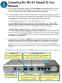
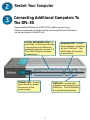
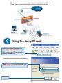
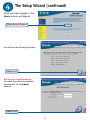
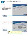
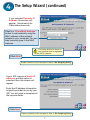
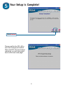
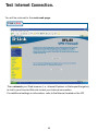
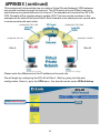
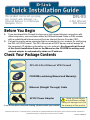
DFL-80
This product can be set up using
any current web browser, i.e.,
Internet Explorer 6 or Netscape
Navigator 6.2.3.
4-Port Ethernet
VPN Firewall
Before You Begin
1. If you purchased this Firewall to share your high-speed Internet connection with
other computers, you must have either an Ethernet-based Cable or DSL modem
with an established Internet account from an Internet Service Provider (ISP).
2. It’s best to use the same computer that is connected to your modem for configuring
the DFL-80 VPN Firewall. The DFL-80 acts as a DHCP server and will assign all
the necessary IP address information on your network. See Appendix at the end
of this Quick Installation Guide or the Manual on the CD-ROM for setting each
network adapter to automatically obtain an IP address.
Check Your Package Contents
DFL-80 4-Port Ethernet VPN Firewall
CD-ROM (containing Manual and Warranty)
Ethernet (Straight Through) Cable
5V DC Power Adapter
If any of the above items are missing, please contact your reseller.
Using a power supply
with a different voltage
rating will damage and void
the warranty of this product.
©2003 D-Link Systems, Inc. All rights reserved. Trademarks or registered trademarks are the property of their respective holders. Software and
specifications subject to change without notice. DFL-80. 03142003
Part No. IG-BDFL80
1
Connecting The DFL-80 Firewall To Your
Network
A. First, connect the power adapter to the receptor at the back panel of the DFL80 and then plug the other end of the power adapter to a wall outlet or power
strip. The Power LED will turn ON to indicate proper operation.
B. 1. Power off your Cable or DSL modem; some devices may not have an on/off
switch and will require you to unplug the power adapter. Now, the DFL-80 should
be powered on and the Cable / DSL modem should be turned off.
2. Cable / DSL modem (Power Off) – DFL-80 (Power On)
Connect an Ethernet cable to the Ethernet jack located on the Cable / DSL
modem. After the Ethernet cable is securely connected, power on the Cable /
DSL modem by turning on the unit or plugging in the power adapter.
3. Cable / DSL modem (Power On) – DFL-80 (Power On)
Insert the other end of the Ethernet cable to the EXTERNAL PORT on the back
panel of the DFL-80. The EXTERNAL LED light will illuminate to indicate proper
connection. If the EXTERNAL LED is not illuminated, please go back to step B
and repeat its instructions.
C. Insert an Ethernet cable to LAN port 1 on the back panel of the DFL-80 and an
available Ethernet port on the network adapter in the computer you will use to
configure the DFL-80. The LED light for LAN Port 1 will illuminate to indicate
proper connection. (Note: The LAN Ports on the DFL-80 are Auto-MDI/MDIX.
Meaning you can use a straight-through or crossover-Ethernet cable to the LAN
Ports.)
D. DMZ port is used to connect to a DMZ network which contains Network Servers.
D. DMZ Port
This is for the connection
to Network Servers.
A. Receptor for
Power Adapter.
B. EXTERNAL PORT
This is for the connection of an Ethernet
cable to the Cable or DSL modem
Reset Button
Pressing this button restores
the Firewall to its original
factory default settings.
2
C. LAN PORTS These are
the connections for Ethernet
cables to Ethernet enabled
computers.
Restart Your Computer
Connecting Additional Computers To
The DFL-80
Using additional Ethernet (CAT5 UTP) cables, connect your
Ethernet-equipped computers to the remaining Ethernet LAN ports
on the back panel of the DFL-80
LOCAL NETWORK LEDs – a
solid light on the port indicates
a connection to an Ethernet
enabled computer on ports 1-4.
This LED blinks during data
transmission.
POWER LED – a solid
light indicates a proper
connection to the
power supply.
External LED – a solid
light indicates connection
on the WAN port. This
LED blinks during data
transmission.
DMZ LED – a solid light
indicates connection on the
DMZ port. This LED blinks
during data transmission.
3
When you have completed the steps in this Quick Installation
Guide, your connected network should look similar to this:
Using The Setup Wizard
Open your Web browser and
type “http://192.168.1.1” into the
URL address box. Then press the
Enter or Return key.
The log-on pop-up screen will appear.
Type “admin” for the username and
“admin” for the password
Click OK
4
The Setup Wizard (continued)
Once you have logged in, the
Home screen will appear.
Click Setup Wizard
You will see the following screens
Click Next
Set up your new password.
You have the option to establish
a password, for the Admin
account
Click Next
5
The Setup Wizard (continued)
Choose your time zone based
from GMT time. Click on Assist to
select your time zone from the
available selections.
Click Next
Select your Internet Connection.
You will be prompted to select the
type of Internet connection for your
network.
Click Next
If you are unsure of which setting to
select, please contact your Internet
Service Provider.
6
The Setup Wizard (continued)
If you selected Dynamic IP
Address, this screen will
appear: (Used mainly for
Cable Internet service.)
Click the “Clone MAC Address”
button to automatically copy the
MAC address of the network
adapter in your computer. You can
also manually type in the MAC
address.
This setup should be done on
the computer that is registered
on the ISP’s network.
Click Next
Please continue to the last part of step 4, Set Outgoing Policy.
If your ISP requires a Static IP
Address, and this option is
selected, then this screen will
appear:
Enter the IP address information
originally provided to you by your
ISP. You will need to complete all
the required fields.
Click Next
Please continue to the last part of step 4, Set Outgoing Policy.
7
The Setup Wizard (continued)
If your ISP uses PPPoE (Pointto-Point Protocol over Ethernet),
and this option is selected, then
this screen will appear: (Used
mainly for DSL Internet service.)
Please be sure to remove any
existing PPPoE client software
installed on your computers.
Enter in the username and
password provided to you by
your ISP.
Click Next
Set Outgoing Policy. You will be
prompted to select the type of
Internet connection for your
network.
Make sure that Any Services
is selected.
Click Next
8
Your Setup is Complete!
Click Restart
Please wait for the DFL-80 to
save the changes and reboot.
When the DFL-80 has finished
rebooting, you will be brought
back to the main web page.
9
Test Internet Connection.
You will be returned to the main web page.
Click to Exit
Then relaunch your Web browser (i.e., Internet Explorer or Netscape Navigator),
to link to your favorite Web site to test your Internet connection.
For additional settings or information, refer to the Manual located on the CD.
10
APPENDIX
To connect to the network, make sure the network adapter in your computer is
configured properly. Here’s how to configure the network adapter to obtain an IP
address automatically for the DFL-80 Firewall.
For Microsoft Windows XP:
Go to Start > right click on
My Network Places >
select Properties > Double-click on
the Network Connection associated
with the Ethernet adapter
(i.e., D-Link DFE-530TX+).
Click Internet Protocol (TCP/IP)
Click Properties
Select Obtain an IP address
automatically
Click OK
Restart your computer
(if necessary)
11
For Apple Macintosh OS X:
Go to the Apple Menu
Click on Network
and Select System
Preferences
Click on
Network
Select Built-in Ethernet
in the Show pull down
menu
Select Using DHCP in
the Configure pull down
menu
Click on Apply Now
The IP address information,
the Subnet Mask, the Router’s
IP address and the Ethernet
adapter address will appear
12
APPENDIX (continued)
This example will demonstrate how to create a Virtual Private Network (VPN) between
two remote locations through the Internet. The VPN policy will use IPSec to securely
send/receive encrypted data over the Internet. This example will consist of two DFL-80
VPN Firewalls with a simple setup to enable VPN. The two remote locations in this
example will be called Site A and Site B. Both firewalls must already be set up and able
to communicate with each other.
(WAN)192.170.0.100
(WAN)192.170.0.200
(LAN)192.168.10.1
(LAN)192.168.20.1
DFL-80
Site A
Site B
Please note the differences in the IP addresses for each site.
We will begin by configuring the DFL-80 at Site A . Start by going into the web
configuration. Once in, go to the VPN menu. You should now be under VPN>Autokey
Click New Entery
13
The IP Address information used for Site A
and Site B are example IP Addresses Only.
Please fill in the appropriate information for Site A.
Name: Site_A
From Source: Internal
Subnet/Mask:
192.168.10.0/255.255.255.0
Remote Gateway – Fixed
IP: 192.170.0.200
Subnet/Mask:
192.168.20.0/255.255.255.0
Authentication Method:
Preshare
Preshare Key: 123456
Encapsulation: Encryption
(ESP)
Click OK
123456 is an example of a preshare key, please fill in any
secret preshare key you desire. Keep in mind that both
sites require the same preshare key.
There should now be a VPN policy created for Site A. Site A is now complete, we will
now configure Site B with the other DFL-80. Follow the same steps previously with Site
A to create a VPN policy. Please change the appropriate IP information.
14
Please fill in the appropriate information for Site B
Name: Site_B
From Source: Internal
Subnet/Mask:
192.168.20.0/255.255.255.0
Remote Gateway – Fixed IP:
192.170.0.100
Subnet/Mask:
192.168.10.0/255.255.255.0
Authentication Method:
Preshare
Preshare Key: 123456
Encapsulation: Encryption
(ESP)
Click OK
123456 is an example of a preshare key, please fill in any
secret preshare key you desire. Keep in mind that both
sites require the same preshare key.
There should now be a VPN policy created for Site B. After the VPN policies have been
created for the two remote locations, click Connect at both Sites to enable the VPN
policy. The two remote locations will authenticate and the VPN status should now say
Connected. Congratulations, you have created a simple IPSec VPN tunnel. Site A and
Site B should now be able to communicate with each other securely over the Internet.
All IP traffic from the two Sites are now encrypted strongly with 168-bit 3DES
encryption.
15
Technical Support
You can find software updates and user documentation on the D-Link website.
D-Link provides free technical support for customers within the United States and
within Canada for the duration of the warranty period on this product.
U.S. and Canadian customers can contact D-Link technical support through our
website, or by phone.
Tech Support for customers within the United States:
D-Link Technical Support over the Telephone:
(877) 453-5465
24 hours a day, seven days a week.
D-Link Technical Support over the Internet:
http://support.dlink.com
email:[email protected]
Tech Support for customers within Canada:
D-Link Technical Support over the Telephone:
(800) 361-5265
Monday to Friday 8:30am to 9:00pm EST
D-Link Technical Support over the Internet:
http://support.dlink.ca
email:[email protected]
16