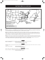
1
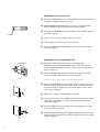
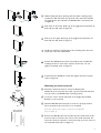
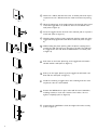
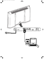
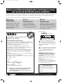
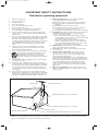
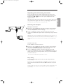
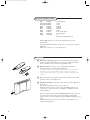
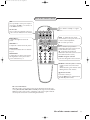
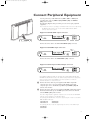
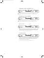
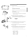
Mounting Wall Bracket Note: the enclosed template can be used for general positioning only (fig. 1). English Mounting to sheetrock wall Note: Bracket can only be used with standard 16" spaced wood wall studs. fig. 1 Bracket must be positioned so that the bracket is fastened firmly to studs at each end. All required hardware is included. Note: Because the Receiver Unit’s power cord is 6’, when determining the Display Unit mounting location, the distance to the nearest AC power outlet must be considered. & Determine desired location to mount Display Unit. fig. 2 420mm /16,54" Within this area, locate the two 16.54" spaced wall studs that must be used as the Wall Bracket mounting location. (fig. 1 and 2) 60,5mm /2.38" fig. 4 é With the Wall Bracket held in place, ensure it is properly leveled. Then, mark where the four holes must be drilled. (fig. 2) fig. 3 Note: Use only the holes in Bracket. “ Remove the Wall Bracket, and using a 13/64" wood drill bit, drill the four holes. (fig. 3) ‘ Reposition the Wall Bracket, and with four lag bolts (fig. 4), secure into place.Tighten with 13mm or 1/2" socket wrench. (fig. 5) Note: Do not use plastic wall anchors with these lag bolts. fig. 5 Note: Lag bolts must be fastened and centered securely into the stud. CORRECTLY INCORRECTLY 1 Mounting to concrete wall & Determine desired location to mount Display Unit. Use the enclosed template for alignment purposes. (fig. 1) é With the Wall Bracket held in place, ensure it is properly leveled. Then, mark where the four holes must be drilled. (fig. 4) “ Remove the Wall Bracket, and using a 5/8" masonry drill bit, drill the four holes. (fig. 2) WASHER ‘ Insert a concrete anchor (with bolt) into each hole. ( Firmly tighten each bolt.Then, remove the bolts. § Reposition the Wall Bracket, and with the four bolts (and washers), secure into place. Mounting to concrete block wall Cavities In Block & Determine desired location to mount the Display Unit. Within this area, position the Wall Bracket so that the four end mounting holes are located over the cavities of the concrete blocks (refer to Figure 1) é With the Wall Bracket held in place, ensure it is properly leveled. Then, mark where the four holes are to be drilled. Fig. 1 Note: Use only the four outside or end holes in the Bracket. “ Remove the Wall Bracket and reconfirm that the marks made in the previous step are located in the cavities of the concrete blocks. Relocate the marks as required to ensure that they are in the cavities of the concrete blocks. ‘ With a 1/2” masonry drill bit, drill the four holes. Fig. 2 ( Hinge the plastic legs of the toggle bolt into the channel of the metal end of the toggle bolt so it can fit into the 1/2” hole drilled in the wall (refer to Figure 2). § Insert the toggle bolt into the hole in the wall and push it in until it is in the cavity of the block. è With the plastic pull ring of the toggle bolt, pull the metal end of the Fig. 3 2 toggle bolt firmly against the back of the cavity of the concrete block (refer to Figure 3). ! While holding the plastic pull ring, slide the plastic retaining sleeve towards the wall until it fits into the hole in the wall. This will hold the toggle bolt in the wall while the Wall Bracket is mounted (refer to Figure 4). Fig. 4 9 Push down on the lower plastic leg of the toggle bolt and break it off flush with the wall (refer to Figure 5). Fig. 5 10 Push up on the upper plastic leg of the toggle bolt and break it off flush with the wall (refer to Figure 6). 11 Install the remaining 3 toggle bolts in the remaining holes the same Fig. 6 way that the first one was installed. 12 Fig. 7 Position the Wall Bracket in place and install the four 1/4-20 bolts, including washers, in each of the outside corner holes. Do not tighten completely (refer to Figure 7). 13 Confirm that the Wall Plate is level, then tighten the bolts securely (refer to Figure 8). Fig. 8 Mounting to metal stud wall & Determine desired location to mount the Display Unit. Metal Wall Studs Within this area, locate the two 16.54” spaced metal wall studs that must be used as the Wall Bracket mounting location. é Locate the center of both wall studs at the height that the Wall Bracket is to be mounted. “ With the Wall Bracket held in place, ensure it is properly leveled. Fig. 1 Holes Centered In Metal Wall Studs Then, mark where the four holes are to be drilled. Note: Use only the four outside or end holes in the Bracket (refer to Figure 1). ‘ Remove the Wall Bracket and reconfirm that the marks made in the previous step are located in the center of the metal wall studs. Relocate the marks as required to ensure that they are in the center of the metal wall studs (refer to Figure 2). Fig. 2 3 ( With a 1/2” drill bit, drill the four holes. A smaller pilot hole may be required if the 1/2” drill bit bends the metal stud instead of piercing it. Fig. 3 § Hinge the plastic legs of the toggle bolt into the channel of the metal end of the toggle bolt so it can fit into the 1/2” hole drilled in the wall (refer to Figure 3). è Insert the toggle bolt into the hole in the wall and push it in past the metal stud (refer to Figure 3). Fig. 4 ! With the plastic pull ring of the toggle bolt, pull the metal end of the toggle bolt firmly against the back of the metal stud (refer to Figure 4). 9 While holding the plastic pull ring, slide the plastic retaining sleeve towards the wall until it fits into the hole in the wall. This will hold the toggle bolt in the wall while the Wall Bracket is mounted (refer to Figure 5). 10 Push down on the lower plastic leg of the toggle bolt and break it off flush with the wall (refer to Figure 6). Fig. 5 Fig. 6 11 Push up on the upper plastic leg of the toggle bolt and break it off flush with the wall (refer to Figure 7). 12 Install the remaining 3 toggle bolts in the remaining holes the same way that the first one was installed. 13 Position the Wall Bracket in place and install the four 1/4-20 bolts, including washers, in each of the outside corner holes. Do not tighten completely (refer to Figure 8). 14 Confirm that the Wall Plate is level, then tighten the bolts securely (refer to Figure 9). Fig. 7 Fig. 8 Fig. 9 4 cover 1016.1 2.4 02-07-2002 09:44 Pagina 2 VIDEO 1 (AV1) VGA 1 RS232 ~ MAINS VGA 2 CVBS B/Pb/Cb H G/Y/Y R/Pr/Cr VIDEO 3 (AV3) V RC-OUT DVI-D Y/C S-VHS VIDEO 2 (AV2) 1016.1 en 02-07-2002 09:46 Pagina 1 Return your Warranty Registration card today to ensure you receive all the benefits you’re entitled to. Once your PHILIPS purchase is registered, you’re eligible to receive all the privileges of owning a PHILIPS product. So complete and return the Warranty Registration Card enclosed with your purchase at once, and take advantage of these important benefits. Warranty Verification Owner Confirmation Model Registration Registering your product within 10 days confirms your right to maximum protection under the terms and conditions of your PHILIPS warranty. Your completed Warranty Registration Card serves as verification of ownership in the event of product theft or loss. Returning your Warranty Registration Card right away guarantees you’ll receive all the information and special offers which you qualify for as the owner of your model. safety ! ry r Hu H REGIS IN 1 0 DA Dear PHILIPS product owner: Thank you for your confidence in PHILIPS.You’ve selected one of the best-built, best-backed products available today. And we’ll do everything in our power to keep you happy with your purchase for many years to come. As a member of the PHILIPS “family,” you’re entitled to protection by one of the most comprehensive warranties and outstanding service networks in the industry. What’s more, your purchase guarantees you’ll receive all the information and special offers for which you qualify, plus easy access to accessories from our convenient home shopping network. And most importantly you can count on our uncompromising commitment to your total satisfaction. All of this is our way of saying welcome-and thanks for investing in a PHILIPS product. Sincerely, Lawrence J. Blanford President and Chief Executive Officer P.S. Remember, to get the most from your PHILIPS product, you must return your Warranty Registration Card within 10 days. So please mail it to us right now! symbols CAUTION T YS DE D WI Congratulations on your purchase, and welcome to the “family!” Know these TION N EE T RA RISK OF ELECTRIC SHOCK DO NOT OPEN CAUTION: TO REDUCE THE RISK OF ELECTRIC SHOCK, DO NOT REMOVE COVER (OR BACK). NO USER-SERVICEABLE PARTS INSIDE. REFER SERVICING TO QUALIFIED SERVICE PERSONNEL. This “bolt of lightning” indicates uninsulated material within your unit may cause an electrical shock. For the safety of everyone in your household, please do not remove product covering. t The “exclamation point” calls attention to features for which you should read the enclosed literature closely to prevent operating and maintenance problems. s WARNING: TO PREVENT FIRE OR SHOCK HAZARD, DO NOT EXPOSE THIS EQUIPMENT TO RAIN OR MOISTURE. CAUTION: To prevent electric shock, match wide blade of plug to wide slot, fully insert. ATTENTION: Pour éviter les choc électriques, introduire la lame la plus large de la fiche dans la borne correspondante de la prise et pousser jusqu’au fond. For Customer Use Enter below the Serial No., which is located on the rear of the cabinet. Retain this information for future reference. Model No. __________________________ Serial No. __________________________ Visit our World Wide Web Site at http://www.philips.com 1 1016.1 en 02-07-2002 09:46 Pagina 2 IMPORTANT SAFETY INSTRUCTIONS Read before operating equipment 1. 2. 3. 4. 5. 6. 7. 8. 9. 10. 11. 12. 13. 14. 15. Read these instructions. Keep these instructions. Heed all warnings. Follow all instructions. Do not use this apparatus near water. Clean only with a dry cloth. Do not block any of the ventilation openings. Install in accordance with the manufacturers instructions. Do not install near any heat sources such as radiators, heat registers, stoves, or other apparatus (including amplifiers) that produce heat. Do not defeat the safety purpose of the polarized or groundingtype plug. A polarized plug has two blades with one wider than the other. A grounding type plug has two blades and third grounding prong.The wide blade or third prong are provided for your safety.When the provided plug does not fit into your outlet, consult an electrician for replacement of the obsolete outlet. Protect the power cord from being walked on or pinched particularly at plugs, convenience receptacles, and the point where they exit from the apparatus. Only use attachments/accessories specified by the manufacturer. Use only with a cart, stand, tripod, bracket, or table specified by the manufacturer, or sold with the apparatus.When a cart is used, use caution when moving the cart/apparatus combination to avoid injury from tip-over. Unplug this apparatus during lightning storms or when unused for long periods of time. Refer all servicing to qualified service personnel. Servicing is required when the apparatus has been damaged in any way, such as power-supply cord or plug is damaged, liquid has been spilled or objects have fallen into apparatus, the apparatus has been exposed to rain or moisture, does not operate normally, or has been dropped. This product may contain lead or mercury. Disposal of these materials may be regulated due to environmental considerations. For disposal or recycling information, please contact your local authorities or the Electronic Industries Alliance: www.eiae.org. 16. Damage Requiring Service - The appliance should be serviced by qualified service personnel when: A. The power supply cord or the plug has been damaged; or B. Objects have fallen, or liquid has been spilled into the appliance; or C. The appliance has been exposed to rain; or D. The appliance does not appear to operate normally or exhibits a marked change in performance; or E. The appliance has been dropped, or the enclosure damaged. 17. Tilt/Stability - All televisions must comply with recommended international global safety standards for tilt and stability properties of its cabinets design. • Do not compromise these design standards by applying excessive pull force to the front, or top, of the cabinet which could ultimately overturn the product. • Also, do not endanger yourself, or children, by placing electronic equipment/toys on the top of the cabinet. Such items could unsuspectingly fall from the top of the set and cause product damage and/or personal injury. 18. Wall Mounting - The appliance should be mounted to a wall only as recommended by the manufacturer. 19. Power Lines - An outdoor antenna should be located away from power lines. 20. Outdoor Antenna Grounding - If an outside antenna is connected to the receiver, be sure the antenna system is grounded so as to provide some protection against voltage surges and built up static charges. Section 810 of the National Electric Code, ANSI/NFPA No. 701984, provides information with respect to proper grounding of the mats and supporting structure grounding of the lead-in wire to an antenna-discharge unit, size of grounding connectors, location of antenna-discharge unit, connection to grounding electrodes and requirements for the grounding electrode. See Figure below. 21. Objects and Liquid Entry - Care should be taken so that objects do not fall and liquids are not spilled into the enclosure through openings. EXAMPLE OF ANTENNA GROUNDING AS PER NATIONAL ELECTRICAL CODE (NEC) GROUND CLAMP ANTENNA LEAD IN WIRE ANTENNA DISCHARGE UNIT (NEC SECTION 810-20) GROUNDING CONDUCTORS (NEC SECTION 810-21) GROUND CLAMPS ELECTRIC SERVICE EQUIPMENT POWER SERVICE GROUNDING ELECTRODE SYSTEM (NEC ART 250, PART H) Note to the CATV system installer :This reminder is provided to call the CATV system installer’s attention to Article 820-40 of the NEC that provides guidelines for proper grounding and, in particular, specifies that the cable ground shall be connected to the grounding system of the building, as close to the point of cable entry as practical. 2 1016.1 en 02-07-2002 09:46 Pagina 3 Unpacking and wall mounting instructions Make sure that the wall mount is being fixed securely enough so that it meets safety standards.The weight of the monitor (excl. packaging) is about 76 lbs. Note: Stands are optional accessories. Consult your dealer. Connect your computer VGA 1 ~ MAINS VGA 2 RC OUT & RS232 Directly to the monitor Connect one end of a VGA cable to the video card of the computer and the other end to the VGA 1 connector at the rear side of the monitor. Fix the connectors firmly with the screws on the plug. é In case of a multimedia computer, connect the audio cable to the audio outputs of your multimedia computer and to the audio inputs of your external amplifier. VGA 2: The video connector for VGA 2 can be programmed to become an input or an output via the Setup menu, see p. 8. The function of being input or output is determined by the used mode. If the monitor is used in TV mode, the VGA 2 connector is VGA output. If the monitor is used in monitor mode,the connector is VGA input or output. To a TV receiver box See the handbook of the TV receiver box. & Connect one end of a VGA cable to the video card of the computer and the other end to the PC/MAC IN connector at the rear side of the TV receiver box. Fix the connectors firmly with the screws on the plug. é In case of a Multimedia computer, connect the audio cable to the audio outputs of your Multimedia computer and to the AUDIO IN R and L inputs of the TV receiver box. For sound reproduction, connect your external amplifier to the TV receiver box. Note: Only use the VGA cable supplied with the monitor. Daisy chaining The Loop Through facility makes it possible to make a daisy chain with a second monitor. Connect one end of another VGA cable to the VGA 2 connector at the rear side of the monitor and the other end to the VGA 1 connector of a second monitor. The RC out jack next to the VGA 2 connector makes it possible to daisy chain remote control signals to other equipment. This output cannot be used to daisy chain a second monitor. 3 English For the unpacking instructions follow the illustrated steps printed on the packaging (outside and inside). For the wall mounting instructions follow the illustrated steps ‘ to § printed on the separate template and in the supplied booklet. 1016.1 en 02-07-2002 09:46 Pagina 4 Use of the remote control Computer Display modes VGA Wide VGA Wide VGA MAC MAC MAC MAC SVGA XGA SXGA 640x480 848x480 852x480 640x480 832x624 1024x768 1152x870 800x600 1024x768 1280x1024 60, 72, 75, 85 Hz 60 Hz 60 Hz 66.67 Hz 74.55 Hz 74.93 Hz 75 Hz 56, 60, 72, 75, 85 Hz 60, 70, 75, 85 Hz 60 72 Hz (not with DVI-D-source) When a VGA computer is connected, the display selection is made automatically. A message is displayed when the monitor does not support the connected VGA mode. Switch your computer to a correct display mode. Operation & Insert the mains plug supplied into the mains inlet at the back of the monitor and in the wall socket. Please, only use the supplied rim-earthed mains cord which has to be inserted in a grounded socket. é Remote control: remove the cover of the battery compartment. Insert the 2 batteries supplied (Type LR6/AA-1.5V). The batteries supplied do not contain the heavy metals mercury and cadmium. Nevertheless in many countries batteries may not be disposed of with your household waste. Please check on how to dispose of batteries according to local regulations. “ Make sure that your TV receiver box and/or PC are switched on and that your PC is in the correct display mode. ‘ Switch the monitor on : Press the power button B at the right side of the monitor. A green indicator lights up and the screen comes on. When the monitor does not receive a supported VGA signal and is not connected to a receiver box the screen switches to standby and the red indicator lights up. R6 / AA B When you switch on your monitor for the first time, and the monitor is not connected to a TV receiver box, the menu language automatically appears on the screen.The explanation appears in different languages one at a time. Follow the instructions on screen to select the correct language or see Setup menu, Language, p. 8. 4 1016.1 en 02-07-2002 09:46 Pagina 5 Use of the remote control VGA press repeatedly to select your computer connected to the VGA 1 or 2 connector or to the DVI-D connector. POWER press to select the peripherals connected to the connector indicated on the monitor. B B AV1, AV2, AV3 VGA AV1 AV2 AV3 CONTRAST BRIGHTNESS ZOOM ON/OFF to switch to standby or on again ZOOM IN ZOOM OUT to switch the menu on/off cursor buttons to select your choice and to alter a selected adjustment. MENU BRIGHTNESS +/- to adjust the brightness level of the picture OK MENU OK to activate your choice CONTRAST +/- to adjust the contrast level of the picture ZOOM ON/OFF to activate/de-activate the zoom function. See p. 7. ZOOM IN/OUT to adjust the zoom factor and to change the magnification of the picture when zoom is activated. See p. 7. V no function (except when in combination with a TV receiver box and a Home Cinema audio receiver) ¬ no function (except when in combination with a TV receiver box and a Home Cinema audio receiver) MUTE V ¬ CH/PR 1 2 3 4 5 6 7 8 9 0 q CH/PR Program selection To browse through the sources selected. AV MUTE AV MUTE to mute the picture or restore it (if the monitor is used in monitor mode). When activated a green indicator starts blinking in front of the monitor. q Picture format See Picture 2 menu, p. 7. Press the q button to switch between the different picture formats. On screen information When the monitor is used in the monitor mode, information about the active source (AV1, AV2, AV3, VGA1, VGA2 or DVI-D) and the supported video,VGA or HD-format of the selected source is displayed on the screen together with the selected picture format and icons informing about AV mute. Use of the remote control 5 1016.1 en 02-07-2002 09:46 Pagina 6 Use of the menus and the menu system 1 Pict. a 2 Pict. a Contrast G H (Color) C Brightness Setup º Color temp. @ (Tint) Sharpness & Press the MENU button on the remote control to summon the different menu headers. é Press the cursor left/right to move the cursor horizontally through the menu headers. “ Press the cursor down to access the menu. è à In case of a slider, move the cursor left/right to adjust. In case of a list with options, move the cursor right to enter and use the cursor up/down to select an option. Press the cursor left to leave the options list. ‘ Press the MENU button again to switch off the menu. Note: Sometimes not all the menu items are visible on the screen. Press the cursor down until all the items are displayed. Only when the US English language has been selected (see Setup menu, Language, p. 8), the menu items will be displayed with additional icons. Operation Press the MENU button on the remote control to summon the main menu. Picture 1 menu SD video-mode Pict. a 1 Brightness G H Color C Contrast This control allows you to adjust the contrast level of the picture. Color temp. @ è à Color (only available when the source is AV1, AV2 or AV3 YCbCr) This control allows you to adjust the saturation level of the colors to suit your personal preference. Contrast (Tint) Sharpness VGA-mode + HD video mode 1 Pict. a Brightness Contrast Color temp. Sharpness 6 Brightness This control allows you to adjust the brightness level of the picture. G H @ à Use of the menus Color temperature This control allows you to select the color temperature of the picture. Move the cursor up/down to make a selection. Press the cursor left to return to the Picture 1 menu. Tint (only with NTSC signals and when the source is AV1 or AV2) This control allows you to compensate for the color variations in NTSC encoded transmissions. Sharpness This control allows you to adjust the edge definition of a picture. 1016.1 en 02-07-2002 09:46 Pagina 7 Picture 2 menu SD video-mode 2 Pict. a Zoom Select Zoom On to activate the zoom function.You may also activate the zoom function with the ZOOM ON/OFF button on the remote control. If no zoom is active, press the cursor left/right, up/down to select which part of the screen will be zoomed. Format q 4:3 Movie expand 16:9 Wide screen Zoom Z Zoom factor  Zoom factor Select Zoom factor and press the cursor left/right to adjust the zoom factor and to change the magnification of the picture. If zoom is not active changing the magnification factor will have no effect on the displayed picture. VGA-mode + HD video mode 2 Pict. a (Format) q 4:3 Wide screen (Phase) Z  ‹ S fi (Auto align) X Zoom Zoom factor (Shift) (Clock frequency) 4:3 VGA-mode 4:3 Wide screen Format (only available in 4:3 VGA mode and SD video mode) Select Format to summon a list of available display formats. Press the cursor up/down to select another display format: 4:3, Movie Expand 16:9 or Wide screen. Note: Movie Expand 16:9 is not available in VGA mode. Shift (only available in VGA mode on VGA 1 or VGA 2 and in one of the HD modes. See Connect Peripheral equipment, p. 9.) This control allows you, when necessary, to move the picture in a horizontal or vertical way. SD video-mode 4:3 Movie expand 16:9 & é Use the cursor left/right, up/down to adjust. Press the OK button when done. Clock frequency (only available in VGA mode on VGA 1 or VGA 2. See Connect Peripheral equipment, p. 9.) This control allows you, when necessary, to adjust the values of the clock frequency so that especially text can be displayed with an optimal overall sharpness. Use the cursor left/right to adjust. Wide screen Phase (only available in VGA mode on VGA 1 or VGA 2. See Connect Peripheral equipment, p. 9.) This control allows you, when necessary, to adjust the pixel phase of the picture to avoid picture interference. Use the cursor left/right to adjust. Auto align (only available in VGA mode on VGA1 or VGA2 and in one of the HD modes. See Connect Peripheral Equipment, p. 9.) This control allows you to automatically adjust the shift, the clock frequency and the phase in VGA mode and the shift in HD modes. Press OK to execute. Use of the menus 7 1016.1 en 02-07-2002 09:46 Pagina 8 Setup menu Language Setup º Language ‡ US English Power savings ) English AV3 ( Nederlands & é “ VGA2 § Deutsch Français Español Use the cursor down to select Language. Press the cursor right to enter the list of selectable languages. Use the cursor up/down to scroll through the list and to bring up other languages which are not displayed on the screen at present. Note: Only with the US English language, the menu items will be displayed with additional icons. Power savings This control allows you to overrule the automatic power savings feature. In case Power savings is switched Off, the power always remains on until the monitor is forced to standby. & é Use the cursor down to select Power savings. Press the cursor left/right to select On or Off. AV3 This control allows you to set the AV3 input to HD-RGB,YCbCr or HDYPbPr.When having selected Auto, the monitor makes the selection automatically between YCbCr, HD-YPbPr or HD-RGB. See also p. 9, Equipment with Component Video Output connectors. & é “ Use the cursor down to select AV3. Press the cursor right to enter the list with options. Press the cursor up/down to select one of the options. VGA 2 This control allows you to select whether to set the VGA 2 connector as input, output or even HD-input. & é Use the cursor down to select VGA 2. “ Press the cursor up/down to select one of the options. Press the cursor right to enter the list with options: VGA IN, VGA OUT or HD IN. Note: AV3 and VGA 2 will not be available in VGA loop through mode, i.e. when a TV receiver box is connected to the monitor and a VGA source is selected. 8 Use of the menus 1016.1 en 02-07-2002 09:46 Pagina 9 Connect Peripheral Equipment You may connect 3 possible VGA sources (VGA 1, VGA 2 or DVI-D) and 3 possible video sources (VIDEO 1 (AV1), VIDEO 2 (AV2) and VIDEO 3 (AV3)) to the monitor. The following diagrams show you where you can connect your peripheral equipment. Note: in case the monitor is operating in combination with a receiver box (TV mode), the VGA and video inputs on the monitor will be disabled and the VGA 2 connector becomes an output. Equipment with Y/C-SVHS output connectors VIDEO 1 (AV1) VGA 1 VGA 2 RS232 DVI-D ~ MAINS MAINS INLET VGA 1 VGA 2 RC OUT CVBS B/Pb/Cb H VIDEO 1 (AV1) Y/C S-VHS VIDEO 2 (AV2) G/Y/Y R/Pr/Cr VIDEO 3 (AV3) B/Pb/Cb H Y/C S-VHS VIDEO 2 (AV2) G/Y/Y R/Pr/Cr VIDEO 3 (AV3) V VIDEO 2 (AV2) RS232 DVI-d CVBS RC-OUT V Connect the video cable to the Y/C S-VHS VIDEO 2 (AV2) connector. Equipment with CVBS output connectors VIDEO 1 (AV1) VIDEO 1 (AV1) VGA 1 VGA 2 CVBS B/Pb/Cb H G/Y/Y R/Pr/Cr VIDEO 3 (AV3) V RC-OUT RS232 DVI-D ~ MAINS Y/C S-VHS VIDEO 2 (AV2) Connect the video cable to the CVBS VIDEO 1 (AV1) connector. Equipment with Component Video Output connectors VIDEO 1 (AV1) VGA 1 RS232 ~ MAINS VGA 2 CVBS B/Pb/Cb H G/Y/Y R/Pr/Cr VIDEO 3 (AV3) V RC-OUT DVI-D Y/C S-VHS VIDEO 2 (AV2) VIDEO 3 (AV3) Note: VIDEO 3 (AV3) can handle the following video signals:YCbCr, HD-PbPr and HD-RGB. The discrimination between the various input formats and the appropriate video processing is done automatically. It is however possible to overrule the automatic detection. See Setup menu, p. 8. & Connect the video cables of your equipment with YPbPr output with composite sync on Y, or of your equipment with YCbCr output with composite sync on Y to the YPbPr, resp.YCbCr input VIDEO 3 (AV3) IN sockets of the monitor. é Connect the video cables of your equipment with RGB output with separate Horizontal and Vertical sync to the RGB input sockets and to the H and V sockets VIDEO 3 (AV3) of the monitor. Note: when High Definition signals are inputted to the monitor via the YPbPr/RGB input, the monitor switches to the HD Video Mode. The following HD and ED video modes are supported by the monitor on the YPbPr, RGB and VGA 2 HD input: 1920x1080/60I 720x480/60P 1280x720/60P 720x576/50P The following SD video modes are supported by the monitor on theYCbCr input: 720x480/60I 720x576/50I 9 1016.1 en 02-07-2002 09:46 Pagina 10 High Definition equipment with VGA connector VGA 2 VIDEO 1 (AV1) VGA 1 VGA 2 CVBS B/Pb/Cb H G/Y/Y R/Pr/Cr VIDEO 3 (AV3) V RC-OUT RS232 DVI-D ~ MAINS Y/C S-VHS VIDEO 2 (AV2) & Connect the VGA output of your equipment to the VGA2 connector. Digital DVI output of your PC (DVI-D) VIDEO 1 (AV1) VGA 1 VGA 2 CVBS B/Pb/Cb H G/Y/Y R/Pr/Cr VIDEO 3 (AV3) V RC-OUT RS232 DVI-D ~ MAINS Y/C S-VHS VIDEO 2 (AV2) DVI-D & Connect the Digital DVI output of your PC to the DVI-D connector. RC out connector RC-OUT VIDEO 1 (AV1) VGA 1 VGA 2 CVBS B/Pb/Cb H G/Y/Y R/Pr/Cr VIDEO 3 (AV3) V RC-OUT RS232 DVI-D ~ MAINS Y/C S-VHS VIDEO 2 (AV2) This connector allows you to daisy chain remote control signals to other equipment (e.g. AV receiver, IR repeater) which have an electrical RC in. Note: it is not possible to daisy chain a second monitor. Serial I/O port RS232 VIDEO 1 (AV1) VGA 1 RS232 ~ MAINS VGA 2 CVBS B/Pb/Cb H G/Y/Y R/Pr/Cr VIDEO 3 (AV3) V RC-OUT DVI-D Y/C S-VHS VIDEO 2 (AV2) RS 232 The RS232 connector is only to be used with the monitor as stand alone. This connector allows you to control the monitor via your PC (as a replacement of the remote control). Note: This connector can also be used for dealer service tools. 10 1016.1 en 02-07-2002 09:46 Pagina 11 Tips Ambient temperature Do not hang up the monitor above a central heating or other heating sources. Care of the screen Clean the anti-reflex coated flat glass screen with a slightly damp soft cloth. Do not use abrasives solvents as it can damage the glass surface of the screen. Plasma Display characteristics Caution: A video source (such as a video game, DVD, or TV information channel) which shows a constant non-moving pattern on the TV screen, can cause damage to the screen.When your Flat-TV is continuously used with such a source, the pattern of the non-moving portion of the game (DVD, etc.) could leave an image permanently on the screen.When not in use, turn the video source OFF. Regularly alternate the use of such video sources with normal TV viewing. When switching over to another picture after having displayed the same still picture for a long time (many hours), it may happen that some parts from the previous picture will remain on screen due to a kind of memory effect.This ghost picture will disappear after some time.To avoid this effect change the pictures regularly or for PC use you can turn on a screen saver in your computer. Philips has built in an automatic shift of the picture in video mode every 5 minutes to avoid this effect and to prolong the life of the screen. Very incidentally and after a longer period of unuse (approx. 1 year) the screen may display some strange color deficiencies. This is quite normal for plasma displays and these effects will disappear after the set has been turned on for some time. A plasma display consists of more than 3.1 Million color pixels. It is within industry standards that very few pixels (< 0.001%) may be defective, even for a new set. There is however no reason to doubt about the quality of the set. The plasma display technology operates with rare gases which are being influenced by air pressure. Up to an altitude of 6562 ft above sealevel, the display is functioning fine. Operating the set at a higher altitude, the picture becomes unstable and the picture performance is deteriorating. Bringing the set below 6562 ft it works fine again. Transportation has no influence. Control of peripheral equipment The infrared radiation of the screen may influence the reception sensitivity of other peripherals. Solution: replace the batteries of the remote control or change position of other equipment. E.g. keep away a wireless headphone from within a radius of 4,92 ft. No stable or not synchronized VGA picture Check if you have selected the correct display mode in your PC. See p. 4, Computer display modes. No picture Are the supplied cables connected properly? (The power cable to the display, the VGA cables,...) Is your PC switched on? Do you see a black screen and the indicator in front of the monitor lights up green, this means that the display mode is not supported. Switch your VGA source to a correct mode. Remote control If your monitor no longer responds to the remote control, the batteries may be exhausted. Transport Keep the original packaging to transport the monitor if needed. End of life directives Philips is paying a lot of attention to produce environmentally-friendly in green focal areas.Your new monitor contains materials which can be recycled and reused. At the end of its life specialized companies can dismantle the discarded monitor to concentrate the reusable materials and to minimize the amount of materials to be disposed of. Please ensure you dispose of your old monitor according to local regulations. How to dispose of batteries ? The batteries supplied do not contain the heavy metals mercury and cadmium. Nevertheless in many countries batteries may not be disposed of with your household waste. Please ensure you dispose of batteries according to local regulations. Miscellaneous . Ambient temperature: + 5~ + 40°C . Maximum operating altitude: 2000 m / 6562 ft (min. pressure 800 hPa) . Mains: AC 95-264V 50/60 Hz . Power consumption: around 290W . Standby consumption: < 2W . Weight (excl. packaging) Display: 76 lbs . Dimensions (wxhxd): Display: 42.3 x 25.9 x 3.5 inch (42”) . Wall mounting bracket included If your problem is not solved: Switch your monitor off and then on again. Never attempt to repair a defective monitor yourself. Check with your dealer or call a TV technician. 11 1016.1 en 02-07-2002 09:46 Pagina 12 LIMITED WARRANTY COLOR TELEVISION 90 Days Free Labor One Year Free Replacement of Parts (Two Years Free Replacement on Color Picture Tube) This product can be repaired in-home. WHO IS COVERED? You must have proof of purchase to receive warranty service. A sales receipt or other document showing that you purchased the product is considered proof of purchase. WHAT IS COVERED? Warranty coverage begins the day you buy your product. For 90 days thereafter, all parts will be repaired or replaced free, and labor is free. From 90 days to one year from the day of purchase, all parts will be repaired or replaced free, but you pay for all labor charges. From one to two years from the day of purchase, you pay for the replacement or repair of all parts except the picture tube, and for all labor charges. After two years from the day of purchase, you pay for the replacement or repair of all parts, and for all labor charges. All parts, including repaired and replaced parts, are covered only for the original warranty period. When the warranty on the product expires, the warranty on all replaced and repaired parts also expires. WHAT IS EXCLUDED? Your warranty does not cover: • labor charges for installation or setup of the product, adjustment of customer controls on the product, and installation or repair of antenna systems outside of the product. • product repair and/or part replacement because of misuse, accident, unauthorized repair or other cause not within the control of Philips Consumer Electronics Company. • reception problems caused by signal conditions or cable or antenna systems outside the unit. • a product that requires modification or adaptation to enable it to operate in any country other than the country for which it was designed, manufactured, approved and/or authorized, or repair of products damaged by these modifications. • incidental or consequential damages resulting from the product. (Some states do not allow the exclusion of incidental or consequential damages, so the above exclusion may not apply to you. This includes, but is not limited to, prerecorded material, whether copyrighted or not copyrighted.) • a product used for commercial or institutional purposes. MAKE SURE YOU KEEP... Please keep your sales receipt or other document showing proof of purchase. Attach it to this owner’s manual and keep both nearby. Also keep the original box and packing material in case you need to return your product. BEFORE REQUESTING SERVICE... Please check your owner’s manual before requesting service. Adjustments of the controls discussed there may save you a service call. TO GET WARRANTY SERVICE IN U.S.A., PUERTO RICO OR U.S. VIRGIN ISLANDS... Contact a Philips factory service center (see enclosed list) or authorized service center to arrange repair. (In U.S.A., Puerto Rico and U.S. Virgin Islands, all implied warranties, including implied warranties of merchantability and fitness for a particular purpose, are limited in duration to the duration of this express warranty. But, because some states do not allow limitations on how long an implied warranty may last, this limitation may not apply to you.) FOR WARRANTY COVERAGE IN CANADA... Note: Product Warranty coverage may vary between countries where product is distributed by Philips Consumer Electronics Company. In order to receive full and specific warranty details for products sold and serviced in Canada, please contact Philips at: 1-800-661-6162 (from Canada - French Speaking) 1-800-531-0039 (English and Spanish Speaking) REMEMBER... Please record the model and serial numbers found on the product below. Also, please fill out and mail your warranty registration card promptly. It will be easier for us to notify you if necessary. MODEL # ________________________________________________ WHERE IS SERVICE AVAILABLE? SERIAL # ________________________________________________ Warranty service is available in all countries where the product is officially distributed by Philips Consumer Electronics Company. In countries where Philips Consumer Electronics Company does not distribute the product, the local Philips service organization will attempt to provide service (although there may be a delay if the appropriate spare parts and technical manual(s) are not readily available). This warranty gives you specific legal rights. You may have other rights which vary from state/province to state/province. Philips Consumer Electronics Company, P.O. Box 520890, Miami, FL 33152, (402) 536-4171 12 126 1014.2 serv. center us 02-07-2002 09:44 Pagina 1 FACTORY SERVICE LOCATIONS • San Francisco/Metro Area Milwaukee ★ Detroit/Toledo • Cleveland/N Ohio • • Chicago ★ Columbus ★ Cincinnati ★ Los Angeles Knoxville/E Tennessee Nashville ★ ★ Charlotte • Chattanooga ★ ¥ • Atlanta/N Georgia • Dallas-Fort Worth ★ Indicates In-Home Service Only Milwaukee: call Chicago Cincinnati and Columbus: call Cleveland Nashville and Chattanooga: call Knoxville Washington/Baltimore: call Philadelphia Charlotte: call Atlanta All Florida locations: call Tampa Los Angeles: call San Francisco Toll-free numbers provided on the next page • •Philadelphia/S New Jersey ★ Washington/Baltimore ★ Orlando • Houston • Tampa/W Florida ★ Ft. Myers/SW Florida ★ Miami/SE Florida Indicates In-Home/Carry-In Service Toll-free numbers provided on the next page Note: If you reside in one of our Philips Factory Service Branch areas (see directory on back), you can contact the nearest Service Branch to obtain efficient and expedient repair for your product. If your product is In-Warranty, you should have proof-of-purchase to ensure No Charge Service. For Out-of-Warranty service, call the location nearest you. Nota: Si vous résidez dans une des régions desservies par une succursale de service après vente du fabricant Philips (voir liste cidessous), vous pourrez contacter la branche de service après vente la plus près de chez vous pour obtenir un service après vente rapide et efficace. Si le produit est sous garantie, il suffira de présenter une preuve d`achat pour bénéficier d'un service sans frais. Pour les produits non couverts par la garantie, contactez le center le plus près de chez vous. Nota: Si Ud. reside en una de nuestras zonas para sucursales Philips de servicio al de fábrica (ver directorio más abajo), Ud. puede comunicarse con la sucursal de servicio más cercana para obtener una reparación oportuna y eficaz de su producto. Si su producto está todavía bajo garantía, Ud. debe presentar comprobante de compra para no ocasionar ningunos cargos por servicio. Para servicio después del vencimiento de la garantía, llame al lugar más cercano de los abajo indicados. In Canada How you can obtain efficient and expedient carry-in, mail-in, or in-home service for your product Please contact Philips at 1-800-661-6162 (French speaking) 1-800-531-0039 (English or Spanish speaking) Au Canada Comment obtenir le service après-vente pour les produits apportés ou envoyés par la poste à notre center de service ou le service à domicile Veuillez contacter philips á: 1-800-661-6162 (Francophone) 1-800-531-0039 (Anglais ou Espagnol) En el Canadá Cómo recibir servicio efficiente para su producto, en persona, por correo o a domicillo Favor de comunicarse con Philips al: 1-800-661-6162 (Francés) 1-800-531-0039 (Inglés o Español) 126 1014.2 serv. center us 02-07-2002 09:44 Pagina 2 FACTORY SERVICE LOCATIONS Qualiy service is as close as your telephone! Simply look over the list below for the number of a Factory Service Center near you. Your product will receive efficient and expedient carry-in, mail-in, or in-home service, and you will receive peace of mind, knowing youru product is being given the expert attetin of Philips’ Factory Service. Comment obtenir notre service après vente rapide et efficace soit par courrier, à domicile, ou en se présentant à un centre de service Philips. Plus de 600 centres de réception de produits à réparer à travers le pays: contacter le centre de service aux consommateurs le plus proche pour savoir l’emplacement de ces dépôts dans un rayon de 50 à 75 miles (80 km à 120 km) du centre de service local. Cómo obtener un servicio oportuno y eficiente por correo, en casa o en persona para su producto a través de un centro Philips de servicio. Mas de 600 sitios por todo el país para la recepción de productos necesitados de reparaciones: comunicarse con el centro de servicio de fabrica mas cercano para estos lugares dentro de un radio de 80 a 120 km (50 a 75 millas) del centro de servicio local. ATLANTA Philips Factory Service 550 Franklin Road., Suite F Marietta, GA 30067 800-273-1501 CLEVELAND Philips Factory Service 950 Keynote Circle Brooklyn Heights, OH 44131 800-331-7037 CHICAGO Philips Factory Service 1279 W. Hamilton Pkwy. Itasca, IL 60143 800-531-2922 TAMPA Philips Factory Service 1911 US Highway 301 North Tampa, FL 33619 800-442-2027 DETROIT Philips Factory 25173 Dequindre Madison Heights, MI 48071 800-438-1398 KNOXVILLE Philips Factory Service 6700 D Papermill Rd. Knoxville,TN 37919 800-821-1767 SAN FRANCISCO Philips Factory Service 681 East Brokaw Rd. San Jose, CA 95112 800-300-9103 DALLAS-FORT WORTH Philips Factory Service 415 N. Main Street, #107 Euless,TX 76040 800-952-3254 PHILADELPHIA Philips Factory Service 352 Dunks Ferry Rd. Bensalem, PA 19020 800-847-9320 HOUSTON Philips Factory Service 1110 N. Post Oak Rd., Suite 100 Houston,TX 77055 800-952-3254