1
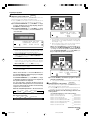
VRS-N8100
KENWOOD CORPORATION
Quick Start Reference
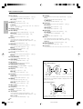
Please read the following pages so that you can enjoy the surround sound at the best
condition.
(These pages give shortcut explanations on how to connect the speaker system to the
receiver, set up the speakers and play a source.)
"Let's play DVD video software" *(
Compared to standard remote controls, the remote control supplied with this receiver has
several operation modes. These modes enable the remote control to control other audio/video
components. In order to effectively use the remote control it is important to read the operating
instructions and obtain a proper understanding of the remote control and how to switch its
operation modes (etc.).
Using the remote control without completely understanding its design and how to switch the
operation modes may result in incorrect operations.
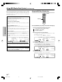
Network Operations
About the supplied remote control
Receiver Operations
INSTRUCTION MANUAL
Preparations
AUDIO VIDEO SURROUND RECEIVER
Remote Control
Additional Information
B60-5489-00 00 MA (K, P, E, X)
*5489/01-08/EN
1
0403
04.7.30, 10:39 AM
Before applying power
Caution : Read this page carefully to ensure safe operation.
Units are designed for operation as follows.
Europe and U.K. ............................................... AC 230 V only
Preparations
U.S.A. and Canada ........................................... AC 120 V only
Australia ........................................................... AC 240 V only
Safety precautions
WARNING : TO PREVENT FIRE OR ELECTRIC SHOCK, DO NOT EXPOSE
THIS APPLIANCE TO RAIN OR MOISTURE.
CAUTION
RISK OF ELECTRIC SHOCK
DO NOT OPEN
CAUTION: TO REDUCE THE RISK OF ELECTRIC SHOCK, DO
NOT REMOVE COVER (OR BACK). NO USER-SERVICEABLE
PARTS INSIDE. REFER SERVICING TO QUALIFIED SERVICE
PERSONNEL.
THE LIGHTNING FLASH WITH ARROWHEAD SYMBOL, WITHIN AN EQUILATERAL TRIANGLE, IS INTENDED
TO ALERT THE USER TO THE PRESENCE OF UNINSULATED “DANGEROUS VOLTAGE” WITHIN THE PRODUCT’S ENCLOSURE THAT MAY BE OF SUFFICIENT MAGNITUDE TO CONSTITUTE A RISK OF ELECTRIC
SHOCK TO PERSONS.
THE EXCLAMATION POINT WITHIN AN EQUILATERAL TRIANGLE IS INTENDED TO ALERT THE USER TO
THE PRESENCE OF IMPORTANT OPERATING AND MAINTENANCE (SERVICING) INSTRUCTIONS IN THE
LITERATURE ACCOMPANYING THE APPLIANCE.
2 EN
*5489/01-08/EN
2
04.7.30, 10:39 AM
Before applying power
How to use this manual
Special features
This manual is divided into five sections, Preparations, Receiver Operations, Network Operations, Remote Control, and Additional Information.
Network function
Preparations
÷ ETHERNET jack
0
÷ PC content editing/managing application
“KENWOOD PC SERVER”
y
Receiver Operations
PC card slot O
Shows you how to operate the various functions available on the
receiver.
A PC card slot is provided on the front panel to enable playback of images
(JPEG) captured with a digital camera.
Network Operations
By installing the application KENWOOD PC SERVER in a PC, the data
stored in the PC can be imported in the libraries for listening to or viewing
music, movie and photographic data in the PC on the libraries.
Remote Control
Shows you how to operate other components using the remote control,
as well as a detailed explanation of all remote control operations. Once
you have registered your components with the proper setup codes, you ’ll
be able to operate both this receiver and your other AV components (TV,
VCR, DVD player, CD player, etc.) using the remote control supplied with
this receiver.
Additional Information
Shows you additional information such as "In case of difficulty" (trouble
shooting) and "Specifications".
Unpacking
True home theater sound ° ~ ‚
This receiver incorporates a wide variety of surround modes to bring you
maximum enjoyment from your video software and audio source. Select
a surround mode according to your equipment or the software you are
going to play and enjoy!
÷ Dolby Digital EX
÷ Dolby PRO LOGIC IIx, Dolby PRO LOGIC II
÷ Dolby Digital
÷ DTS-ES
÷ DTS NEO:6
÷ DTS 96/24
÷ DTS
÷ DSP Mode
÷ Dolby Virtual Speaker
÷ Dolby Headphone
“Supreme” data audio quality improvement technology
Unpack the unit carefully and make sure that all the accessories
are present.
AM loop antenna (1)
(For the U.S.A. and Canada)
Compressed music data such as MP3 data tends to lack expansion
because the high frequencies should be cut off during compression.
“Supreme” is KENWOOD-original technology for reproducing more
realistic sound by estimating and interpolating the high frequencies that
have been lost during compression.
The “Supreme” function is activated when music data that has 44.1 kHz
sampling rate of the MP3, WMA or Ogg Vorbis format is played back.
(The effects are variable depending on the bit rate.)
FM indoor antenna (1)
GAME mode function ¢
When you connect a game machine to the GAME jacks on the front
(For Europe and Australia)
Remote control unit (1)
FM indoor antenna (1)
panel, the input selector of the receiver switches automatically to
"GAME" and the optimum sound field for enjoying games is set.
This feature improves your convenience in playing video games.
DUAL SOURCE function ⁄
While you enjoy audio listening through the speakers, another person
can enjoy another source (audio + video) through headphones by
connecting the source to the GAME, FRONT AUX jacks.
Antenna adaptor (1)
Batteries (R6/AA) (2)
ACTIVE EQ ¤
ACTIVE EQ mode will produce a more dynamic sound quality in any
condition. You can enjoy a more impressive sound effect when ACTIVE
EQ is turned on during Dolby Digital and DTS playback.
Remote control „
Speaker cord connectors
(4)
CD-ROM (Application
KENWOOD PC SERVER)
(1)
In addition to the basic receiver, the remote control supplied with this
receiver can also operate almost all of your remote controllable audio and
video components. Just follow the simple setup procedure to register
the components you have connected.
RDS (Radio Data System) tuner (For Europe) fl
The receiver is equipped with an RDS tuner that provides several
If any accessories are missing, or if the unit is damaged or fails to
operate, notify your dealer immediately. If the unit was shipped to
you directly, notify your shipper immediately. KENWOOD recommends that you retain the original carton and packing materials in
case you need to move or ship the unit in the future.
Keep this manual handy for future reference.
convenient tuning functions: RDS Auto Memory, to automatically preset
up to 40 RDS stations broadcasting different programs; station name
display, to show you the name of the current broadcast station; and PTY
search to let you tune stations by program type.
PTY (Program TYpe) search (For Europe) ‡
Tune the stations by specifying the type of program you want to hear.
3 EN
*5489/01-08/EN
3
04.7.30, 10:39 AM
Preparations
Shows you how to connect your audio and video components to the
receiver and prepare the surround processor. Since this receiver works
with all your audio and video components, we will guide you in setting up
your system to be as easy as possible.
Movie (video), music (audio) and photo (still image) data stored in the PC
can be played back on a TV screen R
Before applying power
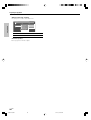
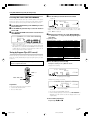
Playable files with this unit
Some files may be unable to be played correctly on this unit depending on the conditions of data, connection environment and the PC in use.
7 Video data (MOVIE file) [Max. file size 2GB]
Preparations
Item
Detail
Audio
Format
Extension
MPEG1
--
MPG/MPEG
Video resolution: 720 x 576 (Max.)/
Bitrate: 1.5 Mbps (Max.)
MPEG1 LAYER 1 & 2
MPEG2
--
MPG/MPEG
Video resolution: 720 x 576 (Max.)/
Bitrate: 8 Mbps (Max.)
MPEG1 LAYER 1 & 2
DivX ® VIDEO *1
--
AVI
Video resolution: 720 x 576 (Max.)
WAV/MP3/
XviD
--
AVI
Dolby Digital
WAV/MP3/
Video resolution: 720 x 576 (Max.)/
Bitrate: 6 Mbps (Max.)
Dolby Digital
7 Audio data (MUSIC file) [Max. file size 2GB]
Item
MPEG Audio
Detail
Format
Extension
MPEG 1 AUDIO
MP1
LAYER 1/ Bitrate: 32~448 kbps/ CBR, VBR/ FS 32k, 44.1k, 48k
MP2
LAYER 2/ Bitrate: 32~384 kbps/ CBR, VBR/ FS 32k, 44.1k, 48k
MP3
LAYER 3 (MP3)/ Bitrate: 32~320 kbps/ CBR, VBR/ FS 32k, 44.1k, 48k
Ver8
WMA
Bitrate: 48~192 kbps/ CBR/ FS 32k, 44.1k, 48k
Ver9
WMA
Bitrate: 48~192 kbps/ CBR, VBR/ FS 32k, 44.1k, 48k
WAV
--
WAV
16 bit/ FS 44.1k, 48k
Ogg Vorbis
--
OGG
Bitrate: 64~256 kbps/ FS 32k, 44.1k, 48k
WMA
7 Photo data (PHOTO file)
Item
Extension
JPEG
Detail
JPG/JPEG
24 bit True Color/ Max. file size 5MB
BMP
24 bit True Color/ Max. file size 5MB
GIF *2
GIF
24 bit True Color/ Max. file size 5MB
PNG *2
PNG
24 bit True Color/ Max. file size 5MB
BMP *2
7 Memory Card
Item
Extension
JPEG
JPG/JPEG
Detail
24 bit True Color/ Max. resolution 2,048 x 1,536/ Max. file size 2MB
*1 Plays DivX®5, DivX®4, DivX®3, DivX®VOD video content (in compliance with DivX CertifiedTM technical requirements)
Official DivX CertifiedTM product
*2 The photo data is converted into the JPEG format data when it is imported in the library.
4 EN
*5489/01-08/EN
4
04.9.8, 4:23 PM
Before applying power
Contents
Caution : Read the pages marked
carefully to ensure safe operation.
Receiver
Operations
Ambience effects .................................. 38
Surround modes ........................... 38
Virtual modes ............................... 40
Surround play ............................... 41
Convenient functions ........................... 43
Adjusting the sound ..................... 43
Display dimmer adjustment ......... 45
Sleep timer ................................... 45
Network
Operations
Installing KENWOOD PC SERVER ....... 46
Uninstalling KENWOOD PC SERVER
..................................................... 47
Updating KENWOOD PC SERVER
..................................................... 47
Operating KENWOOD PC SERVER ...... 48
Names and functions of window components ........................................ 48
Operations using the menu bar ... 48
Import of contents ....................... 49
Playback of Network Server ................ 54
Playback of Memory Card .................... 59
Remote
Control
Basic remote control operations for other
components .......................................... 62
Setup code chart (RC-R0826) (For
U.S.A., Canada and Australia) ...... 64
Setup code chart (RC-R0826E) (For
Europe) ......................................... 69
DVD player , MD recorder, CD player
& TV operations ........................... 76
VCR , Satellite receiver & Cable converter operations ......................... 77
Additional
Information
In case of difficulty................................ 78
Specifications (For U.S.A. and Canada)
........................................................... 81
Specifications (For Europe and Australia)
........................................................... 82
Firmware Update .................................. 83
Let’s play DVD video software ........ 18
Preparing for playback ......................... 20
Speaker settings .......................... 20
Re-assignment of rear panel jacks ... 25
Network settings .......................... 26
Receiver
Operations
Normal playback ................................... 30
Listening to a source component ... 30
Listening with headphones .......... 31
Adjusting the sound ..................... 31
Recording .............................................. 33
Analog sources ............................. 33
Digital sources .............................. 33
Listening to radio broadcasts .............. 34
Tuning (non-RDS) radio stations ... 34
Presetting radio stations .............. 34
Receiving preset stations ............. 35
Receiving preset stations in order
(P.CALL) ........................................ 35
Using RDS (Radio Data System) (For Europe only) .............................................. 36
Using the RDS Disp. (Display) key
..................................................... 36
Tuning by Program TYpe (PTY search)
..................................................... 37
Maintenance of the unit
When the front panel or case becomes dirty, wipe with a soft, dry
cloth. Do not use thinner, benzine, alcohol, etc. for these agents may
cause discoloration.
In regard to contact cleaners
Do not use contact cleaners because it could cause a malfunction. Be
specially careful not to use contact cleaners containing oil, for they
may deform the plastic component.
5 EN
*5489/01-08/EN
5
04.7.30, 10:39 AM
Preparations
Before applying power ...................... 2
Safety precautions ................... 2
How to use this manual ................. 3
Unpacking ....................................... 3
Special features .............................. 3
Playable files with this unit ............ 4
Names and functions of parts ............... 6
Main unit ........................................ 6
Remote control unit ....................... 7
Setting up the system ............................ 9
Connecting Ethernet cable ........... 10
Connecting wireless LAN ............ 10
Connecting a DVD player ............. 11
Connecting video components,
Preparations
audio components ........................ 12
Digital connections ....................... 13
Connecting the speakers ............. 14
Connecting the speaker terminals ... 15
PRE OUT jacks connections ........ 16
Connecting to the GAME jacks /
FRONT AUX jacks ........................ 16
Connecting the antennas ............. 17
Preparing the remote control ....... 17
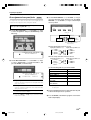
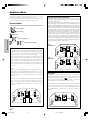
Names and functions of parts
Main unit
TONE indicator, 96kHz fs indicator, AUTO DETECT indicator,
DIGITAL indicator, Sleep Timer indicator
Character information display
CLIP indicator, MUTE indicator, DUAL SOURCE indicator
Preparations
••••••••••••••••••••
••••••••••••••••••••
••••••••••••••••••••
••••••••••••••••••••
Dolby Virtual Speaker indicator,
Dolby Headphone indicator,
ACTIVE EQ indicator, AUTO indicator,
ST. indicator, TUNED indicator
For Europe Only :
RDS indicator, PTY indicator
Speaker indication
8
Display
For Europe and Australia
1
2
3
4
5
^ % View when the GAME/ FRONT AUX jack
cover is open.
1 POWER ON/STANDBY
key
Use to turn the power ON/STANDBY. (For
the U.S.A. and Canada)
)§
ON/STANDBY
key
Use to turn the power ON/STANDBY. (For
Europe and Australia)
)§
STANDBY indicator
Lights when the power is in the standby
mode.
2 DUAL SOURCE VOLUME 5/∞ keys
Use to adjust the volume in the DUAL
SOURCE mode.
⁄
DUAL SOURCE INPUT key
Use to select the input for the DUAL SOURCE
mode.
⁄
DUAL SOURCE ON/OFF key
Use to switch the DUAL SOURCE mode ON/
OFF.
⁄
3 BAND key
Use to select the radio broadcast band.›
4 7 STOP AUTO/MONO key
Use to perform the network server operations.
UŒ
Use to select the auto or manual tuning
mode.
›
5 Dolby D indicator
Lights when the receiver is in the Dolby
Digital mode.
q
9
0
!
@
@ SETUP key
Lights when the DUAL SOURCE mode is ON.
⁄
SUPREME indicator
Lights when the SUPREME function is activated.
3
6 Joystick
MULTI CONTROL % / fi
Use to perform the network setup or speaker
setup.
)§
Also use to switch the REC mode ON and
OFF.
‹
# PC card slot
Use to play images captured using a digital
camera.
O
Use to perform the network setup or speaker
setup.
)§RO
Use to tuning of radio broadcasting. ›
MULTI CONTROL @ / #
Use to perform the network setup or speaker
setup.
)§RO
Use to selection of preset radio stations.
fi
PC card eject button
$ GAME jacks
% FRONT AUX jacks
^ PHONES jack
O
^¢⁄
^⁄
Use for headphone listening.
⁄
ENTER
Use to establish a selection.
)§RO
Use to presetting of radio stations. ›
7 NET LINK indicator
Lights when the connection to the network
is established.
8 LIBRARY INFO key
Use to display the library list of the PC server
I
Standby mode
Use to select the listening mode.
q
Use to adjust the receiver volume.
º
Use to select input sources.
º
While the standby indicator is lit, a small
amount of power is supplied to the system to
back up the memory. This is called standby
mode. Under the condition, the system can
be turned ON by the remote control unit.
on the display of this unit.
Lights when the receiver is in the DTS mode.
q
0 VOLUME CONTROL knob
Dolby H indicator
! INPUT SELECTOR key
EN
6
8
#
DUAL SRC indicator
9 LISTEN MODE key
*5489/01-08/EN
7
$
DTS indicator
Lights when the Dolby Headphone mode is
ON.
‚
6
6
04.7.30, 10:39 AM
Names and functions of parts
Remote control unit
This remote control unit can be use not only for Kenwood products but also for other non-Kenwood products by setting the appropriate manufacturer’s
setup codes. ‰
For the U.S.A., Canada and Australia: RC-R0826
For Europe : RC-R0826E
4
DEF
3
P. Call
Enter
0
9
Music
Sleep
Input
Mode
Menu
+ 100
TV Mute
Movie
!
@
#
$
%
^
&
*
(
+ 10
Search
Photo
Guide
Angle
OSD
£
¢
∞
Page
+
¢
+
Mute
VOL
CH
–
4
–
TV
VOL
Sound
+
–
TV Input
Tune –
Tune +
Auto
Top Menu
Zoom
Setup
Input Sel.
Dimmer
Video Out
Exit
TV
Band
Info
Return
Disk Sel.
Rotate
Last/P.Mode
Active
EQ
Disc Skip
Listen Mode
Dolby
Virtual
Stereo
Remote
Setup
MNO
6
Multi
PQRS
2
Enter
7
TUV
Multi
8
Clear
Subtitle
8
4
§
¶
•
ª
º
⁄
¤
‹
›
fi
1
5
6
7
+ 100
TV Mute
Movie
0
9
Music
Sleep
Input
Mode
Menu
Clear
£
¢
∞
+ 10
Search
Audio
Subtitle
Guide
Photo
Angle
RDS Disp.
9
0
8
WXYZ
Home
8
¡
™
o
VP w
ABC
7
WXYZ
Audio
9
0
DEF
5
TUV
1
Home
JKL
4
P. Call
P. Call
2
GHI
3
PQRS
F.AUX
Game
POWER
RCVR
C Po
6
Multi
5
6
7
3
MNO
Multi
ABC
4
¡
™
Memory
Card
T
T
5
o
VP w
Network
Server
RCV
Mode
er
JKL
2
r
we
GHI
AUX
VID2
F.AUX
Game
er
SR
Memory
Card
POWER
RCVR
C Po
r
we
3
RCV
Mode
DVD
VID1
P. Call
Network
Server
VID2
2
TUNER
1
AUX
SR
1
DVD
Preparations
)
)
TUNER
VID1
OSD
PTY
Page
+
¢
+
Mute
!
@
#
$
%
^
&
*
(
Sound
–
–
TV
VOL
§
VOL
CH
4
+
–
TV Input
Tune –
Dimmer
Tune +
Auto
Top Menu
Video Out
Exit
Zoom
Return
Info
¶
•
ª
º
⁄
¤
‹
›
fi
TV
Band
Setup
Input Sel.
Disc Sel.
Rotate
Last/P.Mode
Active
EQ
Disc Skip
Listen Mode
Dolby
Virtual
Stereo
Remote
Setup
If the name of a function is different on the receiver and on the remote control, the name of the remote control key in this manual is indicated in parentheses.
1 Input Selector keys (TUNER, DVD, VID 1, VID 2, AUX,
F. AUX, Game, Network Server, Memory Card)
5 Home key
Use to perform the network server operations. TP
Use to select input sources. º
+100 key
Sources keys (DVD, VID 1, VID 2, AUX, F. AUX, Game)
Use to operate other components. „
To control one of the registered sources without switching the receiver's
input selector to that source, press and hold the desired input selector key
for more than 3 seconds. „
TV Mute key
2 RCV (receiver) Mode key
Use to temporarily mute the TV sound. „
6 Music key
Use to perform the network server operations. R
Use to switch the remote control to the receiver control
mode. e
3 SRC (source) Power key
Use to turn the other components ON/OFF. „
4 Numeric keys
Use to input numeric or alphabetic characters. §U
Use to selection of preset radio stations. fi
Use to operate other components. „
Clear key
Use to clear a character input by mistake. §U
Multi (%/fi) keys
Use to perform the network setup or speaker setup.
)§RO
Use to tuning of radio broadcasting. ›
Use to operate other components. „
P.Call @/# keys
Use to perform the network setup or speaker setup.
)§RO
Use to selection of preset radio stations. fi
Enter key
Input Mode key
Use to switch between the full auto, digital and analog input. 9
7 Movie key
Use to perform the network server operations. R
Audio key
Use to operate the DVD component. „
8 Photo key
Use to perform the network server operations. R
Angle key
Use to operate the DVD component. „
9 Page 5/∞ keys
Use to perform the network server operations. TP
Use to operate the DVD component. „
(For Europe only)
RDS Disp. key
Use to receive RDS broadcast. fl
PTY key
Use for PTY search.
‡
Use to establish a selection. )§RO
Use to operate other components. „
*5489/01-08/EN
7
Continued to next page
7 EN
04.7.30, 10:39 AM
Names and functions of parts
0 ¢ / 4 keys
º Setup key
Use to perform the network server operations. UŒ
Use to operate the CD, DVD or MD component. „
CH +/- keys
Top Menu key
Use to select the channels. „
Use to operate the DVD component. „
Preparations
! Mute key
Use to temporarily mute the sound. ¤
Sound key
Use to adjust the sound quality and the ambience
effects. ⁄¤e
@ TV VOL +/- keys
„
Use to adjust the TV’s volume.
Use to perform the network setup or speaker setup. )§
¶ key
Use to operate the MD or VCR component. „
# Video Out key
Use to switch the video output temporarily. ¶I
Dimmer key
Use to adjust the brightness of the display. t
8 key
Use to operate other components. „
$ 3/8 key
Use to perform the network server operations. U
Use to operate the CD, DVD, MD or VCR component. „
Band key
Use to select the broadcast band. ›
% Return key
Use to perform the network server operations. UŒ
Use to operate the DVD component. „
Exit key
⁄ Rotate key
Use to perform the network server operations. IŒ
Disc Sel. key
Use to operate other components. „
Input Sel. key
Use to operate other components. „
¤ P.Mode key
Use to perform the network server operations. U
Disc Skip key
Use to operate the the multi-CD player . „
Last key
Use to operate other components. „
‹ 7 key
Use to perform the network server operations. UŒ
Use to operate the CD, MD, DVD or VCR component. „
Auto key
Use to select the auto or manual tuning mode. ›
› Remote Setup key
Use to register other components. „
fi Stereo key
Use to switch the listen mode temporary to the stereo mode.
w
Use to operate other components. „
^ Listen Mode 5/∞ keys
Use to select the listening mode. q
& Zoom key
Use to perform the network server operations. IŒ
Info key
Use to operate other components.
„
* Dolby Virtual key
Use to select the Dolby Virtual mode. ‚
( Active EQ key
Use to select ACTIVE EQ ’s setting. ¤
) LED indicator
Blinks to show that signals are being transmitted.
¡ POWER RCVR (receiver) key
Use to turn the receiver ON/STANDBY. )§
™ TV Power key
Use to turn the TV on and off.
Speaker indication
Output channel indicators :
SW
L
C
R
„
£ Sleep key
Use to set the Sleep timer.
t
Menu key
Use to operate other components. „
¢ Search key
Use to perform the network server operations. U
Subtitle key
Use to operate the DVD component. „
∞ OSD key
LS
RS
LB
BS
RB
The output channel indicators light up to indicate the audio signals
output from this unit. Headphone display is displayed when head-
Use to operate the memory card. Œ
Use to operate the DVD component. „
phones are connected.
Guide key
Input channel indicators :
Use to operate other components.
„
§ VOL +/- keys
Use to adjust the receiver volume. º
Headphone indicators
LFE
L
C
R
¶ TV Input key
Use when in TV operation.
„
• TV key
Use when in TV operation.
„
ª 1 / ¡ keys
Use to perform the network server operations. U
Use to operate the CD, DVD, MD or VCR component. „
Tune +/- keys
Use to tuning of radio broadcasting.
›
LS
RS
LB
BS
RB
The Input channel indicators lights up to indicate the channels
contained in the input signal.
8 EN
*5489/01-08/EN
8
04.7.30, 10:39 AM
Setting up the system
Input mode settings
CAUTION
Make sure that the power cord plug is disconnected from the AC wall
outlet before proceeding to connections. Also be sure to disconnect the
power cord plug from the AC wall outlet before changing connections.
For the connections of other system components, see pages 10 to 17.
VIDEO 1, VIDEO 2, AUX and GAME are full auto.
After completing connections and turning on the receiver, follow the
steps below.
INPUT SELECTOR
Microcomputer malfunction
If operation is not possible or an erroneous display appears,even
though all connections have been made properly, reset the micro
computer referring to "In case of difficulty".
k
Notes
Input Selector keys
1. Be sure to turn off the system components before connecting them.
2. Be sure to insert every connection cable completely into the jack.
Incomplete connection may result in absence of audio output or
production of noise.
3. Be sure to disconnect the power cord from the AC wall outlet before
Input Mode
inserting or removing a connection cable.
4. Installation of outdoor antenna is a dangerous work. Please have your
dealer or a specialized technician install it.
5. Select the speaker installation locations with care. If a speaker is
installed near a source of magnetism including a magnet, the mutual
interference with the speaker may produce color irregularities on the
TV screen.
1 Use the INPUT SELECTOR key (or Input Selector keys)
to select DVD, VIDEO 1, VIDEO 2, AUX or GAME.
Analog audio connections
Audio connections are made using RCA pin cords. These cables transfer
stereo audio signal in an "analog" form. This means the audio signal
corresponds to the actual audio of two channels. These cables usually
have 2 plugs on each end,one red for the right channel and one white for
the left channel.
These cables are to be prepared separately by the user.
CAUTION
Be sure to adhere to the following, or proper ventilation will be
blocked causing damage or fire hazard.
÷ Do not place any objects impairing heat radiation onto the top of
the unit.
÷ Leave some space around the unit (from the largest outside
dimension including projection) equal to or greater than, shown
below.
Top panel
Side panel
: 50 cm
: 10 cm
Back panel
: 10 cm
2 Press the Input Mode key.
Each press switches the setting as follows:
1 Auto detect:
("AUTO DETECT" indicator lights up)
2 Fixed to digital input:
("DIGITAL" indicator lights up)
3 Fixed to analog input: *
("AUTO DETECT", "DIGITAL" indicator goes off)
*
Can not be selected for DTS playback.
Auto detect:
In FULL AUTO mode ("AUTO DETECT" indicator lights up), the
receiver detects the digital or analog input signals automatically.
The receiver will select the input mode and listening mode
automatically during playback to match the type of input signal
(Dolby Digital, PCM, DTS) and the speaker setting. q
The "DIGITAL" indicator lights up when a digital signal is
detected. The "DIGITAL" indicator is extinguished when no
digital signal is detected.
Fixed to digital input:
Select this mode if you want to keep the decoding condition
(Dolby Digital, DTS, PCM, etc.) in the current listen mode.
When DIGITAL MANUAL mode is selected, the set listen modes
may be changed automatically depending on the listen
mode.
q
Fixed to analog input:
Select this setting to play analog signals from a VCR, etc.
If the Input Mode key is pressed quickly, sound may not be
produced. Press the Input Mode key again.
9 EN
*5489/09-17/EN
9
04.7.30, 10:39 AM
Preparations
When connecting an associated system component, be sure to read
its instruction manual.
DVD, VIDEO 1, VIDEO 2, AUX and GAME inputs each include jacks
for digital audio input and analog audio input.
The initial factory settings for audio signal playback for DVD,
Setting up the system
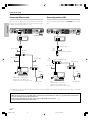
Connecting wireless LAN
When not using a broadband router or hub, connect this unit directly to
the PC using a cross Ethernet cable. In this case, it is required to set the
IP address and subnet mask manually. ª
Connect the wireless Ethernet bridge to the ETHERNET jack on the rear
panel.
Preparations
Connecting Ethernet cable
To AC wall outlet
ETHERNET
ETHERNET
*
*
Ethernet cable
Ethernet cable
Broadband
Wireless Ethernet bridge
router
Ethernet cable
Ethernet cable
Wireless broadband router
Ethernet cable
Ethernet cable
Modem
Modem
To
Internet
To
Internet
PC:
Windows XP Professional SP1,
Windows XP Home Edition SP1,
Windows 2000 Professional SP4 or after.
Modular cable
PC:
Windows XP Professional SP1,
Windows XP Home Edition SP1,
Modular cable
Windows 2000 Professional SP4 or after.
*
Please refer to the instruction manual of your router or hub. Depending on your router or hab they may in rare case not work with
a cross Ethernet cable.
÷ This unit is not provided with the Internet connection facility.
÷ When this unit is connected to a PC, FM broadcast reception may be interfered with noise. In this case, try the following remedial actions.
1. Increase the distance between this unit and the PC.
2. When the provided FM indoor antenna is in use, replace it with the FM outdoor antenna.
3. Replace the Ethernet cable with a shielded cable.
&
10 EN
*5489/09-17/EN
10
04.7.30, 10:39 AM
Setting up the system
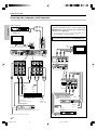
Connecting a DVD player
If you have connected a DVD player to the receiver with digital connection, be sure to read the "Input mode settings", "Re-assignment of rear panel jacks"
section carefully. 9∞
Preparations
Monitor TV
COMPOSITE
VIDEO IN
(Yellow RCA pin cords)
S VIDEO IN
(S VIDEO cord)
COMPONENT
VIDEO IN
COMPONENT
VIDEO
OUTPUT
DVD
IN
Y
CB
CR
VIDEO 2
IN
S VIDEO
MONITOR
OUT
MONITOR
OUT
COMPONENT
VIDEO INPUT
(ASSIGNABLE)
(VIDEO 2)
DIGITAL IN (ASSIGNABLE)
OPT 1
(VIDEO 1)
COAX 2
(VIDEO 2)
IN 2
IN 1
(DVD)
OPT 2
(AUX)
DVD
IN
Y
CB
VIDEO 2
IN
S VIDEO
MONITOR
OUT
VIDEO IN
CR
COAX 1
(DVD)
IN
DVD
COMPONENT
VIDEO OUT
DIGITAL OUT (AUDIO)
(Coaxial cord)
S VIDEO OUT
(S VIDEO cord)
AUDIO LINE OUT
or MIX LINE OUT
(Audio cord)
COMPOSITE
VIDEO OUT
(Yellow RCA pin
cords)
DVD player
÷ Digital audio connections are required when playing multi-channel signals such as the Dolby Digital and DTS signals.
÷ To play the DVD player connected in this page, select the "DVD" input selector. º
11 EN
*5489/09-17/EN
11
04.7.30, 10:39 AM
Setting up the system
Connecting video components, audio components
Preparations
Audio components
Connecting video components (COMPONENT VIDEO)
If you have connected the receiver to a video component with
COMPONENT jacks, you can get a better picture quality than by
connecting to the S VIDEO jacks.
AUDIO LINE OUT (Audio cord)
When connecting a video component with COMPONENT jacks,
see "Re-assignment of rear panel jacks" ∞
Monitor TV
When connecting the TV to the COMPONENT jacks, be sure to
connect all the other components to the COMPONENT jacks.
L
IN
AUX
MONITOR
OUT
VIDEO IN (Yellow RCA pin cords)
R
CB IN
Y IN
CR IN
Monitor TV
(with component jacks)
COMPONENT
VIDEO
OUTPUT
Y
VIDEO IN
VIDEO OUT
VIDEO IN
VIDEO IN
PLAY IN REC OUT PLAY IN
VIDEO 2
VIDEO 1
VIDEO OUT
CB
CR
VIDEO IN
PLAY IN REC OUT PLAY IN
VIDEO 2
VIDEO 1
COMPONENT
VIDEO INPUT
(ASSIGNABLE)
(VIDEO 2)
IN 2
IN 1
(DVD)
VIDEO
OUT
(Yellow
RCA pin
cords)
AUDIO
LINE
IN
(Audio
cord)
Y
HDD Recorder, DVD Recorder,
Satellite Receiver & Game
Player (with component jacks)
Video deck, Cassette
deck or MD recorder
VIDEO IN
(Yellow RCA pin cords)
CB
CR
CR OUT
AUDIO
LINE OUT
(Audio cord)
Satellite Receiver
CB OUT
Y OUT
CB OUT CR OUT
AUDIO LINE OUT or MIX LINE OUT (Audio cord)
DVD player (with component jacks)
VIDEO OUT (Yellow RCA pin cords)
Y OUT
12 EN
*5489/09-17/EN
12
04.7.30, 10:39 AM
Setting up the system
Digital connections
The digital in jacks can accept DTS,Dolby Digital,or PCM
Connecting video components (S VIDEO)
nents with S VIDEO IN/OUT jacks.
¶ If you use the S VIDEO jacks to connect your video playback
connection,be sure to read the "Input mode settings", "Re-assignment
of rear panel jacks" section carefully. 9∞
components, be sure to use the S VIDEO jacks when connecting your monitor and video recording components.
DVD
IN
VIDEO 2
IN
S VIDEO
MONITOR
OUT
DIGITAL IN (ASSIGNABLE)
COAX 2
(VIDEO 2)
OPT 1
(VIDEO 1)
OPT 2
(AUX)
COAX 1
(DVD)
S VIDEO IN
(S VIDEO cord)
Monitor TV
(with S VIDEO jack)
CD player or DVD player
OPTICAL DIGITAL OUT (AUDIO)
(Optical fiber cord)
S VIDEO OUT (S VIDEO cord)
Component with DTS,
Dolby Digital,or PCM
Satellite Receiver
(with S VIDEO cord)
OPTICAL DIGITAL OUT
OPTICAL DIGITAL
OUT (AUDIO)
(Optical fiber cord)
Connect the analog audio signals
to the AUX jacks.
(See "Connecting video components, audio components ". @)
S VIDEO OUT (S VIDEO cord)
COAXIAL DIGITAL
DVD player
(with S VIDEO jack)
OUT (AUDIO)
(Coaxial cord)
Satellite Receiver
Connect the video signal and analog audio signals to the VIDEO 2
jacks.
(See "Connecting video components, audio components ". @)
DTS disclaimer clause
When playing DTS-encoded discs, excessive noise will be exhibited from the analog stereo outputs of the CD or DVD player. To
enjoy DTS Digital Surround™ playback, this unit must be connected to the digital output of the CD or DVD player.
13 EN
*5489/09-17/EN
13
04.7.30, 10:39 AM
Preparations
Use the S VIDEO jacks to make connections to video compo-
signals.Connect components capable of outputting DTS,Dolby Digital or PCM (CD) digital signals.
If you have connected a DVD player to the receiver with digital
Setting up the system
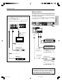
Connecting the speakers
Whether each speaker is connected properly can be
confirmed by outputting the test tone and checking if
each speaker channel outputs audio. For details, see
"Speaker settings" (Step 6 Adjust the speaker volume
level). £
Preparations
CAUTION
Make sure that the power cord plug is disconnected from the AC
wall outlet before proceeding to speaker cord connections.
If the conductor wires on the extremity of speaker cord are
untwisted, there is a risk of short-circuiting. Be sure to twist
them well before connecting the speaker cord.
Protection circuitry
This unit incorporates protection circuitry, which may be activated
during high-power reproduction or in case of extreme rise in temperature.
When the protection circuitry is activated, the output from this unit is
shut down and the STANDBY indicator blinks.
In this case, turn this unit OFF then ON again and reduce the output
volume level.
Front Speakers
Surround Speakers
Be sure to connect both surround speakers.
Right
Surround Back Speaker
Left
Right
Center
Left
When the surround back speaker is connected to
these terminals, set the speaker setting to "BS/
SW Amp Back Surr.". ™
In this case, the subwoofer should be connected
to the PRE OUT SUBWOOFER jack. ^
Subwoofer
Speaker
When the subwoofer is connected to these terminals, set the speaker setting to "BS/SW Amp
Subwoofer". ™
In this case, two surround back speakers should be
connected to the PRE OUT SURROUND BACK
jacks. ^
SPEAKERS (6-8Ω)
CENTER
SURR R
SURR BACK SURR L
/SW
R
FRONT
L
14 EN
*5489/09-17/EN
14
04.7.30, 10:39 AM
Setting up the system
Connecting the speaker terminals
Front
1 Strip coating.
¶ Never short circuit the + and – speaker cords.
¶ If the left and right speakers are connected inversely or the
speaker cords are connected with reversed polarity, the sound
will be unnatural with ambiguous acoustic imaging. Be sure to
connect the speakers correctly.
3 Insert.
Speaker impedance
2 Loosen.
After confirming the speaker impedance indications printed on the
rear panel of the receiver, connect speakers with matching impedance ratings. Using speakers with a rated impedance other than that
indicated on the rear panel of the receiver could result in malfunctions
or damage to the speakers or receiver.
4 Secure.
Speaker placement
Center, Surround, Surround back, Subwoofer,
Subwoofer
Center speaker
Attaching the speaker cord connectors;
Connect each speaker cord by matching the color of the connector
with that of the terminal to which the speaker cord is to be
connected.
Before connection, strip the vinyl coating by about 1 cm ( 0.4 in.)
from each end of each speaker cord and twist the conductor wires
Surround
speakers
Front
speakers
Listening
position
so that they are not unbraided.
Connected speaker
Connector
Connected
terminal
Center speaker
Green
CENTER
Surround speaker (Right)
Grey
SURR R
Surround speaker (Left)
Blue
SURR L
Surround back speaker
or Subwoofer
Brown
SURR BACK/SW
While applying the projected part of the connector against a hard
desktop, etc., insert the conductor sections of the speaker cord
into the connector.
Projected part
(White)
¶ After attaching the speaker cord connector, hold it and pull the speaker
cord lightly to ensure that it will not come out.
Connect the connector to the terminal on the receiver with the
same color by inserting the connector straight until it clicks.
Green
Brown
*Surround Back
*Left speaker
*Surround Back
*Right speaker
*Surround Back speaker
* For Surround Back speaker, you may place either two Surround
Back speakers (Surround Back Left speaker and Surround Back
Right speaker) for 7.1 channel surround sound system or one
Surround Back speaker for 6.1 channel surround sound system.
Front speakers : Place the left and right speakers at each side of your TV.
Angle the speakers towards the listening area to enhance the stereo
effect.
Center speaker : Place the center speaker on the center between the
front left and right speakers. Tilt the speaker upward or down-ward so
that it is directly facing the listening area.
Surround speakers : Place the surround speakers as high as possible,
either directly to the sides of the listening area or else slightly behind
the listening area. Adjust the angles so that these speakers are facing
directly towards the listeners.
Subwoofer : Usually, place the subwoofer in the front center position in
the listening room, near one of the front speakers near the center
speaker. (Since the subwoofer has less directivity than other speakers,
it can be placed almost in any position that can offer the best low
frequency reproduction according to the room layout.)
Surround back speakers : Place the surround back speaker behind the
listining position, at the same height as the left and right surround
speakers.
¶ Although the ideal surround system consists of all the speakers listed
above, if you don't have a center speaker or a subwoofer, you can
divide those signals between the available speakers in the speaker
settings steps to obtain the best possible surround reproduction from
the speakers you have available. )
Grey
CENTER
SURR R
SURR BACK
/SW
SURR L
Confirm the connector
orientation before insertion.
Blue
Be sure to use speaker cords matching the following requirements:
[AWG24-18 standard (conductor section diameter 0.511 to 1.024
mm(0.02 to 0.04 in.))]
15 EN
*5489/09-17/EN
15
04.7.30, 10:39 AM
Preparations
Twist
Setting up the system
PRE OUT jacks connections
Connecting to the GAME jacks / FRONT AUX jacks
The receiver has additional PRE OUT jacks.
Note that the output from the PRE OUT jacks needs to be connected
to an external power amplifier.
If you want to connect surround back speakers to these jacks, be always
sure to connect two surround back speakers for the left and right.
If you use a component that you do not usually connect to the receiver,
such as a portable video camera, connect it to the GAME or FRONT AUX
jacks on the front panel of the receiver. These jacks are particularly
convenient when dubbing audio/video from a portable video camera.
Preparations
INPUT SELECTOR
FRONT AUX
R
GAME
L
SUB
WOOFER SURROUND BACK
PRE OUT
Example:
¶ When you want to connect two surround back
speakers.
¶ When the subwoofer is connected to the
SURR BACK/SW terminals.
Surround Back speakers
R
L
Power amplifier
OPTICAL
DIGITAL
OUT
(AUDIO)
VIDEO
OUT
AUDIO
OUT
VIDEO
OUT
AUDIO
OUT
Example:
¶ When the surround back speaker is connected to
the SURR BACK/SW terminals.
Subwoofer
Camcorder
Power amplifier
Powered subwoofer
Game Player
¶ Connecting a speaker cord directly to a PRE OUT jack will not
produce any sound from the speaker.
¶ The DIGITAL IN (OPTICAL) jack in the GAME jack section can be
used for connection of digital audio input. This is convenient for
playing a video game through the receiver. ¢
16 EN
*5489/09-17/EN
16
04.7.30, 10:39 AM
Setting up the system
Connecting the antennas
Preparing the remote control
The broadcast reception cannot be made unless the antennas are
connected. Connect the antennas correctly as instructed below.
AM loop antenna
1 Remove the cover.
2 Insert the batteries.
Preparations
The supplied loop antenna is for use indoors. Place it as far as possible
from the receiver, TV set, speaker cords and power cord, and adjust the
direction for best reception.
Loading the batteries
AM antenna terminal connections
1 Push lever.
2 Insert cord.
3 Release lever.
3 Close the cover.
FM indoor antenna
The supplied indoor antenna is for temporary use only. For stable signal
reception we recommend using an outdoor antenna. Disconnect the
indoor antenna when you connect one outdoors.
¶ Insert two AA-size (R6) batteries as indicated by the polarity markings.
FM antenna terminal connections
Insert the connector
Remote control operation
(For the U.S.A. and Canada)
(For Europe and Australia)
When the STANDBY indicator is lit, the power turns ON when you press
the POWER RCVR on the remote control. When the power comes ON,
press the key you want to operate.
FM outdoor antenna
Lead the 75Ω coaxial cable connected to the FM outdoor antenna into the
room and connect it to the FM 75Ω terminal.
Remote sensor
Operating other
component range
For the U.S.A. and Canada
FM indoor antenna
For Europe and Australia
Antenna adaptor
POWER RCVR
FM indoor antenna
¶ When pressing more than one remote control key successively,
press the keys securely by leaving an interval of 1 second or more
between keys.
ANTENNA
Notes
FM 75 Ω
GND
AM
Attach to the stand
White
1. The supplied batteries may have shorter lives than ordinary batteries
due to use during operation checks.
2. When the remote-controllable distance gets shorter than before,
replace both batteries with new ones.
The remote control unit is designed so that the setup codes stored in
it are saved even after the batteries are removed for replacement.
Black
AM loop antenna
Use an antenna
adaptor
(Commercially
available)
3. Placing the remote sensor in direct sunlight, or in direct light from a
high frequency fluorescent lamp may cause a malfunction.
In such a case, change the location of the system installation to
prevent malfunction.
FM outdoor antenna
17 EN
*5489/09-17/EN
17
04.7.30, 10:39 AM
Let’s play DVD video software
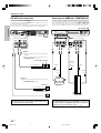
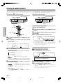
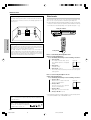
STEP 1 Connect the speakers, TV and DVD to the receiver
Preparations
For details, see "Setting up the system" 9 ~ ^
CAUTION
Make sure that the power cord plug is disconnected from the AC wall outlet before proceeding to speaker cord connections.
If the conductor wires on the extremity of speaker cord are untwisted, there is a risk of short-circuiting. Be sure to twist them well before
connecting the speaker cord.
Connection of speakers:
C
A
B
C
Front speakers (L,R)
Center speaker
Subwoofer
D
Surround speakers (L,R)
E
Surround back speaker
L
B
1~
RECEIVER
1~
SW
R
DVD
C
÷ If you want to connect two surround back speakers (LB and RB)
to the PRE OUT SURROUND BACK jacks, see "PRE OUT jacks
connections". ^
LS
RS
Listening position
A
D
E
BS
3
2
1
SPEAKERS (6-8Ω)
COMPONENT
VIDEO INPUT
(ASSIGNABLE)
COMPONENT
VIDEO
OUTPUT
Y
CB
CR
DIGITAL IN (ASSIGNABLE)
ANTENNA
COAX 2
(VIDEO 2)
FM 75 Ω
GND
AM
OPT 1
(VIDEO 1)
(VIDEO 2)
IN 2
(DVD)
IN 1
DVD
IN
OPT 2
(AUX)
Y
COAX 1
(DVD)
CB
CR
VIDEO 2 MONITOR
IN
OUT
S VIDEO
R
VIDEO IN
VIDEO IN
VIDEO OUT
VIDEO IN
MONITOR
OUT
L
L
CENTER
SURR R
SURR BACK
/SW
SURR L
ETHERNET
SUB
WOOFER SURROUND BACK
PRE OUT
1 2 3
4
IN
DVD
PLAY IN REC OUT PLAY IN
VIDEO 2
VIDEO 1
IN
AUX
R
R
FRONT
L
5
Connection of DVD player:
Connection of TV monitor:
1
Component video connection
1
Component video connection
2
3
S video connection
Composite video connection
2
3
S video connection
Composite video connection
÷ For the video input connection from the DVD player and the video
output connection to the TV monitor, connect any one in a pair.
4
5
Digital audio connection (Coaxial cord)
Analog audio connection
18 EN
*5489/18-29/EN
18
04.7.30, 10:39 AM
C
A
B
D
E
Let’s play DVD video software
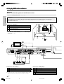
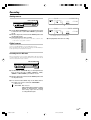
STEP 2 Set up the speakers
POWER ON/STANDBY
ON/STANDBY
For details, see "Speaker settings" . ) ~ ¢
INPUT SELECTOR
SETUP
2 Press
, press
or
.
to select "SPEAKER SETUP" and press
.
Preparations
ENTER
MULTI CONTROL %/fi/@/#
1 Connect the power cord to the AC wall outlet and press
If you connect KENWOOD speaker system KS-2100HT, KS-3100EX, KS-708HT, KS-308HT, KS-708HT+KS-308EX, KS-308HT+ KS-308EX, KS-908HT or KS-908EX:
Press
to select the model of the connected speaker system and press
"HTB1 6.1CH": Speaker system KS-3100EX.
"HTB1 5.1CH": Speaker system KS-2100HT.
"HTB2 6.1CH": Speaker system KS-708HT+KS-308EX or
KS-308HT+ KS-308EX.
If your selection is correct, press
to select "YES" and press
.
"HTB2 5.1CH": Speaker system KS-708HT or KS-308HT.
"HTB3 6.1CH": Speaker system KS-908EX.
"HTB3 5.1CH": Speaker system KS-908HT.
Model availability may differ depending on the country and sales area.
. Now the speaker setup is complete. (Select "NO" to return to the status before setup.)
÷ When the speaker setting is set to "HTB1 5.1CH", "HTB2 5.1CH" or "HTB3 5.1CH", the PL IIx, DTS-ES and DOLBY EX listen modes cannot be selected.
If you use another speaker system want a setup according to it:
Press
Press
to select "CUSTOM" and press
to select each of the speaker setup items.
to select the speaker setup item
Press
to select the setting for each item
"SUBWOOFER"
"SUBWOOFER ON": A subwoofer is connected.
"SUBWOOFER OFF": A subwoofer is not connected.
"FRONT"
Speaker size ?
"LARGE": Relatively large-size speakers.
"NORMAL": Normal-size speakers.
"CENTER", "SURROUND", "BACK SURROUND"
Speaker size ?
"LARGE": Relatively large-size speakers.
"NORMAL": Normal-size speakers.
"OFF": No speaker is connected.
"BS/SW AMP"
"BS/SW AMP BACK SURROUND": A surround back speaker is connected to the SURR
BACK/SW terminals.
"BS/SW AMP SUBWOOFER": A subwoofer is connected to the SURR BACK/SW terminals.
"BS/SW AMP OFF": No speaker is connected.
After completing the setup, press
. If your selection is correct, press
to select "YES" and press
.
Now the speaker setup is complete. (Select "NO" to return to the status before setup.)
÷ When the speaker setting is set to "BS/SW AMP OFF", the PL IIx, DTS-ES and DOLBY EX listen modes cannot be selected.
÷ More detailed settings such as the volume level of each speaker and distance to each speaker are also available. £¢
STEP 3 Play a disc on the DVD player
1 Press
to select "DVD".
2 Start playback of the DVD player.
For the operation, also refer to the instruction manual for your DVD player.
÷ You can select various listen modes to enjoy surround playback of various kinds of video software.
q
19 EN
*5489/18-29/EN
19
04.7.30, 10:39 AM
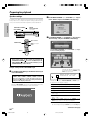
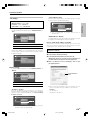
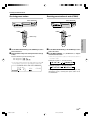
Preparing for playback
Speaker settings
2 Use the MULTI CONTROL @/ # (or the Multi @/ # keys) to
To enable you to obtain optimum enjoyment from the receiver’s listening
select “SETUP”, and press the ENTER (or the Enter key) .
modes, make sure to complete the speaker settings (subwoofer, front,
center, surround and surround back speakers) as described below.
WARNING
Preparations
Could not detect server.
Please chek following item.
ENTER
MULTI CONTROL
%/fi/@/#
POWER ON/STANDBY
ON/STANDBY
1. Starting server
2. Starting PC application
3. Install PC application
4. Network connection & setting
SETUP
SETUP
RETRY
3 Use the MULTI CONTROL %/ fi (or the Multi %/ fi keys) to select
“Receiver Setup”, and press the ENTER (or the Enter key).
Input selector
Setup Menu
NET LINK PC SERVER1
POWER RCVR
Multi %/fi/@/#
Enter
Receiver Setup
Network Setup
Exit
Setup
Return
Use the MULTI CONTROL @/ # (or the Multi @/ # keys)
for the following displays.
Receiver Setup
Speaker
Setup
Speaker
Level
Assainment
Speaker
Distance
Game
Function
LEF Level
Preparation
Turn on the power to this receiver by pressing the
POWER ON/STANDBY (For U.S.A. and Canada) or the
ON/STANDBY (For Europe and Australia) key (or the
POWER RCVR key on the remote).
Exit
C
L
SW
R
LS
RS
BS
Example: Setting with the “NET SERVER” input
1 Use the INPUT SELECTOR key (or the Network Server key) to
Indicates the direction of movement in
the hierarchy when the ENTER (or the
Enter key) is pressed.
select “NET SERVER”.
When performing the speaker setup by selecting the
“TUNER”, “DVD”, “VIDEO1”, “VIDEO2”, “GAME” or “F.AUX”
input, press the SETUP (or Setup) key and start the procedure from step 3. In these cases, the setting information is
displayed on the display of this unit.
When the “NET SERVER” input is selected, the OSD function on the
TV screen is activated and detection of the server starts.
SEARCHING
RECEIVER SETUP
SPEAKER SETUP
Indicates the direction of MULTI CONTROL (or Multi key) to
be pressed for selecting the setting.
1 “Speaker Setup”: Select a speaker system. ¡
2 “Speaker Level”: Adjust the speaker volume level. £
3 “Speaker Distance”: Input the distance to the speakers.
£
4 “Assignment”: Re-assignment of rear panel jacks ∞
5 “LFE Level”: Adjust the LFE LEVEL (Low Frequency Effects
level) ¢
6 “Game Function”: Set up the GAME jacks on the front
panel. ¢
7 “Exit”: Select “Exit” and press the ENTER (or the
Enter key) to return to the previous display.
÷ While the main setup screen is displayed, the setup mode can
be canceled by pressing the SETUP key (or the Setup key).
Continued to next page
20
EN
*5489/18-29/EN
20
04.7.30, 10:39 AM
Preparing for playback
4 Select the setup method.
Speaker Setup
If you selected “Custom” in the above:
1 Select “Speaker Setup” and press the ENTER key (or
the Enter key) to select the speaker setup method.
2 Use the MULTI CONTROL @ / # (or the Multi @ / # keys)
for the following displays.
Press the ENTER (or the Enter key) to proceed to detailed setups.
After this, continue the procedure from step 5.
The flow of the SETUP is as follows;
SPEAKER SETUP
HTB 1
HTB 2
HTB 3
Custom
6.1ch
5.1ch
6.1ch
5.1ch
6.1ch
Exit
5.1ch
Front
Center
R
Back Surr.
LS
RS
BS/SW
Amp
BS
SW Re-mix
RECEIVER SETUP
SPEAKER SETUP
HTB1 6.1ch
Digital
Input
Component
Video
Left
Exit
Game
Function
Exit
Mode 1
Mode 2
Off
Right
Right Surr.
Left
Center
Right
Right Surr.
Back Surr.
(RB/ LB)
Left Surr.
Subwoofer
Surround
Meters
Feet
Exit
Center
Test Tone Manual
Test Tone Off
C
SW
Assignment
LEF Level
Left
Center
Right
Right Surr.
Back Surr.
(RB/ LB)
Left Surr.
Subwoofer
Subwoofer
L
Speaker Distance
Test Tone Auto
Back Surr.
(RB/ LB)
Left Surr.
Subwoofer
Exit
5 Select a speaker system.
1 Use the MULTI CONTROL % / fi (or the Multi % / fi keys)
to select the appropriate subwoofer setting.
Speaker Setup Custom
1 “HTB1 6.1CH”: Select “HTB1 6.1CH” if you use speaker
system KS-3100EX. *
Subwoofer
2 “HTB1 5.1CH”: Select “HTB1 5.1CH” if you use speaker
system KS-2100HT. *
On
3 “HTB2 6.1CH”: Select “HTB2 6.1CH” if you use speaker
system KS-708HT+KS-308EX or KS-308HT+KS-308EX. *
4 “HTB2 5.1CH”: Select “HTB2 5.1CH” if you use speaker
system KS-708HT or KS-308HT. *
C
L
SW
R
LS
RS
BS
5 “HTB3 6.1CH”: Select “HTB3 6.1CH” if you use speaker
system KS-908EX. *
6 “HTB3 5.1CH”: Select “HTB3 5.1CH” if you use speaker
system KS-908HT.*
7 “Custom”: Select to set up the speakers according to the
speaker system in use. (Speaker setup is required every
time after the speaker system is changed.)
8 “Exit”: Select “Exit” and press the ENTER (or the Enter key)
to return to the previous display.
* Model availability may differ depending on the country
and sales area.
÷ When the 5.1 channel speaker system configuration is
used or the speaker setting is set to “BS/SW Amp Off”,
the PL IIx, DTS-ES and DOLBY EX listen modes cannot
be selected.
If you selected “HTB1 6.1CH”, “HTB1 5.1CH”, “HTB2 6.1CH”,
“HTB2 5.1CH”, “HTB3 6.1CH” or “HTB3 5.1CH” in the above:
Press the ENTER (or the Enter key), then press the MULTI
CONTROL % / fi (or the Multi % / fi keys) to select “Yes”, and
press the ENTER (or the Enter key) again to establish the setup.
÷ Select “No” to return to the status before setup.
÷ When you use a KENWOOD speaker system and select
“HTB1 6.1CH”, “HTB1 5.1CH”, “HTB2 6.1CH”, “HTB2
5.1CH”, “HTB3 6.1CH” or “HTB3 5.1CH” set the speaker
setup, the audio will be corrected automatically according to the speaker characteristics.
RECEIVER SETUP
SPEAKER SETUP
SUBWOOFER
ON
1 “Subwoofer On”:
When a subwoofer is connected.
2 “Subwoofer Off”:
When no subwoofer is connected.
÷ The initial setting is “Subwoofer On”.
÷ When “Subwoofer Off” is selected and the selection is established by pressing the MULTI CONTROL # (or the Multi # key)
in step 2 below, the front speakers are set automatically to
“Front Large” and the procedure jumps to step 5.
2 Use the MULTI CONTROL # (or the Multi # key)
to accept the setting.
3 Use the MULTI CONTROL % / fi (or the Multi % / fi keys)
to select the appropriate front speakers setting.
1 “Front Large”:
Large front speakers are connected to the receiver.
Continued to next page
21 EN
*5489/18-29/EN
21
04.7.30, 10:39 AM
Preparations
Speaker Setup
SPEAKER LEVEL
HTB 1 6.1CH
HTB 1 5.1CH
HTB 2 6.1CH
HTB 2 5.1CH
HTB 3 6.1CH
HTB 3 5.1CH
Custom
Exit
Preparing for playback
2 “Front Normal”:
Preparations
Average size front speakers are connected to the receiver.
÷ When the subwoofer setting is “Subwoofer On”, front
speakers setting is “Front Large” and a stereo source
is played, the low frequencies may be reproduced
through the front speakers and no audio output from the
subwoofer in certain listen modes. In this case, set the
subwoofer re-mix setting in step # to “SW Re-mix On”
to output the low frequencies from the subwoofer.
4 Use the MULTI CONTROL # (or the Multi # key)
to accept the setting.
5 Use the MULTI CONTROL % / fi (or the Multi % / fi keys)
to select the appropriate center speaker setting.
1 “Center Large”:
*
A large center speaker is connected to the receiver.
2 “Center Normal”:
An average size center speaker is connected to the receiver.
3 “Center Off”:
When no center speaker is connected.
*
“Center Large” cannot be selected when the front
speakers have been set to “Front Normal”.
6 Use the MULTI CONTROL # (or the Multi # key)
to accept the setting.
7 Use the MULTI CONTROL % / fi (or the Multi % / fi keys)
to select the appropriate surround speaker setting.
1 “Surround Large”:
0 Use the MULTI CONTROL # (or the Multi # key)
to accept the setting.
! Use the MULTI CONTROL % / fi (or the Multi % / fi keys)
to select the appropriate BS/SW amp setting.
1 “BS/SW Amp Back Surr.”:
Select this setting when a surround back speaker is connected to the SURR BACK/SW terminals. In this case, the
subwoofer signal will be output from the PRE OUT
SUBWOOFER jack.
2 “BS/SW Amp Subwoofer”:
Select when the subwoofer speaker is connected to the
SURR BACK/SW terminals. In this case, the surround back
signals will be output from the PRE OUT SURROUND BACK
jacks.
3 “BS/SW Amp Off”:
Select when no speaker is connected to the SURR BACK/
SW terminals. In this case, the subwoofer signal will be
output from the PRE OUT SUBWOOFER jack and the surround back signals will be output from the PRE OUT SURROUND BACK jacks.
÷ If “BS/SW Amp Back Surr.” is selected, only one surround back speaker can be connected to the receiver.
÷ If “BS/SW Amp Subwoofer” or “BS/SW Amp Off” is
selected, two surround back speakers can be connected
to the PRE OUT SURROUND BACK jacks through an
external power amplifier. ^
@ Use the MULTI CONTROL # (or the Multi # key)
to accept the setting.
Large surround speakers are connected to the receiver.
2 “Surround Normal”:
Average size surround speakers are connected to the receiver.
3 “Surround Off”:
When no surround speakers are connected.
÷ When “Surround Off” is selected and the selection is
established by pressing the MULTI CONTROL # in step
8 below, the procedure jumps to step #. However, if
the subwoofer setting is “Subwoofer Off”, the procedure jumps to step $ so that you can complete the
speaker setup and proceed to the speaker volume level
adjustment in step 6.
8 Use the MULTI CONTROL # (or Multi # key) to accept the setting.
9 Use the MULTI CONTROL % / fi (or the Multi % / fi keys)
to select appropriate surround back speaker setting.
1 “Back Surr. Large”:
*
Large surround back speaker is connected to the receiver.
2 “Back Surr. Normal”:
Average size surround back speaker is connected to the
receiver.
# Use the MULTI CONTROL % / fi (or the Multi % / fi keys)
to select the appropriate subwoofer re-mix setting.
If “SW Re-mix On” is selected as the subwoofer re-mix
setting, the low frequencies are enhanced by adding the
low frequencies of other channels to the subwoofer channel or adding the low frequencies of the subwoofer to
other channels depending on the speaker setup.
1 “SW Re-mix On”:
Subwoofer re-mix setting mode to the receiver is ON.
2 “SW Re-mix Off”:
Subwoofer re-mix setting mode to the receiver is OFF.
÷ The initial setting is “SW Re-mix On”.
÷ The subwoofer re-mix setting is possible only when the
subwoofer setting is “Subwoofer On” and the front
speaker setting is “Front Large”.
$ Press the ENTER (or the Enter key). If your selection
is correct, press the MULTI CONTROL % / fi (or the
Multi % / fi key) to select “Yes”.
Press the ENTER (or the Enter key) again to return to
the main setup displays.
÷ Select “No” and press the ENTER (or the Enter key) to
return to the status before setup.
3 “Back Surr. Off”:
When no surround back speakers is connected.
*
“Back Surr. Large” cannot be selected when the surround speaker has been set to “Surround Normal” or
Continued to next page
“Surround Off”.
22
EN
*5489/18-29/EN
22
04.7.30, 10:39 AM
Preparing for playback
6 Adjust the speaker volume level.
Speaker Level
Test Tone Auto
From your usual listening position, adjust the volume levels. The
Left
volume levels from each speaker should be the same.
÷ In this step 6, only the speaker channels that have been set
0 dB
and require the volume level adjustment are displayed.
00 dB
00 dB
LS
L
Test Tone
Manual
Test Tone
Off
00 dB
00 dB
R
00 dB
00 dB
BS
RS
00 dB
SPEAKER LEVEL
TEST TONE AUTO
LEFT
0dB
Speaker Level
Test Tone
Auto
C
SW
Preparations
1 Use the MULTI CONTROL @ / # (or the Multi @ / # keys)
to select “Speaker Level” on setup displays, and press
the ENTER (or the Enter key).
2 Use the MULTI CONTROL @ / # (or the Multi @ / # keys)
to select “Test Tone Auto”, “Test Tone Manual “ or
“Test Tone Off”.
Exit
RECEIVER SETUP
SPEAKER LEVEL
TEST TONE AUTO
1 “Test Tone Auto”: Select this setting to adjust the speaker
volume levels using the test tone. The test tone will be output
from every speaker channel in automatic sequence.
÷ If you change the volume level settings for the speakers while
listening to music, the settings referred to on this page are
also changed. e
÷ When a speaker setup is set to off the volume level for
the corresponding speakers is reset to 0 dB.
When “Test Tone Manual” or “Test Tone Off” is selected, press the MULTI CONTROL @/# (or the Multi
@/# key) to select the speaker channel and then
press the MULTI CONTROL %/fi (or the Multi %/fi
key) to adjust the speaker volume level.
2 “Test Tone Manual”: Select the speaker channel to
output the test tone using the MULTI CONTROL@ / #
Test Tone Manual
Left
(or the Multi @ / # key).
0 dB
3 “Test Tone Off”: Select to adjust the speaker volume
levels using the current output signals. The speaker
channel to output the signal can be selected using the
00 dB
MULTI CONTROL@ / # (or the Multi @ / # key).
00 dB
4 “Exit”: Select “Exit” and press the ENTER (or the Enter key)
LS
L
C
00 dB
SW
00 dB
R
00 dB
00 dB
RS
to return to the previous display.
BS
00 dB
÷ Press the SETUP (or Setup) key to cancel the SETUP
mode in the middle.
SPEAKER LEVEL
TEST TONE MANUAL
LEFT
0dB
When “Test Tone Auto” or “Test Tone Manual” is selected and the ENTER (or the Enter key) is pressed again,
the test tone output will start.
Use the MULTI CONTROL % / fi (or the Multi % / fi keys)
to adjust the volume level of the test tone output from
the speaker channel to be adjusted.
For “Test Tone Auto” selection, the first test tone is
heard from the front left speaker for 2 seconds. The next
test tone is heard from the speakers in the following
sequence for 2 seconds each.
When the “BS/SW Amp Back Surr.” has been selected:
Left
Center
Subwoofer
Right
Right Surround
Left Surround
Back Surround
When the “ BS/SW Amp Subwoofer ” or “BS/SW Amp
Off” has been selected:
Left
Subwoofer
Center
Left Surround
Right
Right Surround
Left Back Surround
Right Back Surround
3 Press the ENTER (or the Enter key) again to return to
the main setup displays.
÷
The test tone is turned off and return to the main setup
displays.
7 Input the distance to the speakers.
Speaker Distance
This setting allows the signals output from different speakers to
reach the listening position simultaneously.
÷ In this step 7, only the speaker channels that have been set
and require the volume level adjustment are displayed.
Measure the distance from the listening position to each
of the speakers.
Jot down the distance to each of the speakers.
Distance to Front speaker (L)
Distance to Center speaker (C)
Distance to Front speaker (R)
Distance to Surround speaker (RS)
Distance to Surround back speaker (RB)
Distance to Surround back speaker (LB)
Distance to Surround speaker (LS)
Distance to Subwoofer (SW)
:
:
:
:
:
:
:
:
____ feet (meters)
____ feet (meters)
____ feet (meters)
____ feet (meters)
____ feet (meters)
____ feet (meters)
____ feet (meters)
____ feet (meters)
Continued to next page
23 EN
*5489/18-29/EN
23
04.7.30, 10:39 AM
Preparing for playback
1 Use the MULTI CONTROL @ / # (or the Multi @ / # keys)
to select “Speaker Distance” on setup displays, and
press the ENTER (or the Enter key).
2 Use the MULTI CONTROL @ / # (or the Multi @ / # key)
to select the unit and press the ENTER (or the Enter key).
Preparations
Feet
0dB
÷ The LFE LEVEL is adjusted from 0dB to -10dB in 1dB
step decrements.
Speaker Distance
Meters
RECEIVER SETUP
LFE LEVL
EL
3 Press the ENTER (or the Enter key) again to return to
the main setup displays.
Exit
9 Set up the GAME jacks on the front panel.
RECEIVER SETUP
SPEAKER DISTANCE
METERS
1 “Meters”
2 “Feet”
Perform the setup for convenience of playing a video game using the
receiver.
1 Use the MULTI CONTROL @ / # (or Multi @ / # keys)
to select “Game Function” on setup displays, and press
the ENTER (or the Enter key).
2 Press the MULTI CONTROL % / fi (or the Multi % / fi
key) to select the game mode.
3 “Exit”: Select “Exit” and press the ENTER (or the Enter key)
to return to the previous display.
Game Function
Mode 1
÷ Press the SETUP (or Setup) key to cancel the SETUP
mode in the middle.
Mode 2
Off
3 Use the MULTI CONTROL @ / # (or the Multi @ / # keys)
to select the speakers and the MULTI CONTROL % / fi
(or the Multi % / fi keys) to adjust the distance to the
front speakers.
÷ The speakers you have selected should appear on the display.
Confirm that all the speakers have been correctly selected.
Game Function
C
L
SW
R
LS
RS
BS
Speaker Distance Meters
RECEIVER SETUP
GAME FUNCTION
Left
3.0 m
MODE
3.0 m
3.0 m
L
C
1
3.0 m
SW
R
1 “ Mode 1 ” :
3.0 m
When the connected game machine is turned ON, the input
LS
1.5 m
1.5 m
BS
RS
selector is switched automatically to “GAME”. In addition, the
1.5 m
ACTIVE EQ function is switched to “ACTIVE EQ GAME” and
the listen mode is switched to the appropriate mode for games.
RECEIVER SETUP
SPEAKER DISTANCE
LEFT
3.0m
÷ The allowable setting range is 1 to 30 feet (0.3 to 9.0 m),
adjustable in 1 foot (0.3 m) increments.
4 Repeat steps 3 to input the distance for each of the
speakers.
5 Press the ENTER (or the Enter key) again to return to
the main setup displays.
8 Adjust the LFE LEVEL (Low Frequency Effects level).
LFE Level
Adjust the level of the low-frequency fields effect (LFE) signal, which
is the signal used exclusively for giving the field effect of bass tone,
in the Dolby Digital or DTS signal.
1 Use the MULTI CONTROL @ / # (or the Multi @ / # keys)
to select “LFE Level” on setup displays, and press the
ENTER (or the Enter key).
2 Use the MULTI CONTROL % / fi (or the Multi % / fi keys)
to adjust the LFE LEVEL.
2 “ Mode 2 ” :
When the connected game machine is turned ON, the input
selector is switched automatically to “GAME”.
3 “ OFF ” :
The game mode is switched OFF.
÷ Press the SETUP (or Setup) key to cancel the SETUP
mode in the middle.
÷ The game mode is not activated if no video signal is
input to the VIDEO jack in the GAME jack section.
÷ The game mode is not activated when the DUAL SOURCE
function is switched ON.
LFE Level
0 dB
24 EN
*5489/18-29/EN
24
⁄
3 Press the ENTER (or the Enter key) again to return to
the main setup displays.
04.7.30, 10:39 AM
Preparing for playback
Re-assignment of rear panel jacks
Assignment
The assignment of the input selector positions to the digital audio and
component video input jacks can be changed as desired.
3 Use the MULTI CONTROL @/# (or the Multi @/# key) to
select the input jack name and then press the MULTI
CONTROL % /fi (or the Multi % /fi key) to select the input
selector position.
Digital Input
Perform the operations in “Preparation” in “Speaker settings”
)
Coaxial 2
Optical 1
Optical 2
DVD
VIDEO 2
VIDEO 1
VIDEO 2
Preparations
and its procedure steps 1 to 3.
Coaxial 1
1 Use the MULTI CONTROL @ / # (or the Multi @ / # keys)
to select “Assignment” and press the ENTER key (or the
Input jack
Enter key).
ASSIGNMENT
DIGITAL INPUT
COAX1 DVD COAX2 V2
OPT1
V1
OPT2
AUX
Receiver Setup
Speaker
Setup
Speaker
Level
Assignment
Speaker
Distance
LEF Level
Game
Function
Exit
C
L
Input selector
SW
R
When the "Digital Input" has been selected :
LS
RS
BS
RECEIVER SETUP
ASSIGNMENT
Input jack selection (@/#)
1 "Coaxial 1"
2 "Coaxial 2"
3 "Optical 1"
4 " Optical 2"
Input selector position (%/fi)
1
2
3
" DVD "
" VIDEO 2 "
" VIDEO 1 "
4 " AUX "
When the "Component Video" has been selected :
Input jack selection (@/#)
2 Use the MULTI CONTROL @ / # (or the Multi @ / # keys)
to select “Digital Input” or “Component Video”, and
press the ENTER (or the Enter key).
1 " Component 1 "
2 " Component 2 "
Input selector position (%/fi)
1 " DVD "
2 " VIDEO 2 "
3 " VIDEO 1 "
Assignment
Use the following table for your memorandum.
Digital
Input
Component
Video
Exit
Jack name
Assigned input selector
COAX1 (DVD)
RECEIVER SETUP
ASSIGNMENT
DIGITAL INPUT
COAX2 (VIDEO 2)
OPT1 (VIDEO 1)
OPT2 (AUX)
COMPONENT VIDEO INPUT
IN1 (DVD)
1 “Digital Input”:
Select to change the assignment of the digital audio input
jacks of the receiver.
2 “ Component Video ” :
Select to change the assignment of the component video
COMPONENT VIDEO INPUT
IN2 (VIDEO 2)
÷ It is not permitted to assign two input selector positions for
one input jack.
input jacks of the receiver.
3 “Exit”: Select “Exit” and press the ENTER (or the Enter key)
to return to the previous display.
÷ Press the SETUP (or Setup) key to cancel the SETUP
mode in the middle.
4 Repeat step 3 until you have assigned the desired jacks
to the desired input selector positions.
5 Press the ENTER (or the Enter key) again to return to the
main setup displays.
25 EN
*5489/18-29/EN
25
04.7.30, 10:39 AM
Preparing for playback
3 Use the MULTI CONTROL %/fi (or the Multi %/fi keys) to select
Network settings
“Network Setup”, and press the ENTER (or the Enter key) .
This unit can be connected to a PC through a LAN circuit.
It is required to set up the network before connecting this unit to the PC.
Setup Menu
NET LINK PC SERVER1
Receiver Setup
Preparations
Network Setup
INPUT SELECTOR
POWER ON/STANDBY
ON/STANDBY
ENTER
MULTI CONTROL
%/fi/@/#
Exit
4 Use the MULTI CONTROL %/fi (or the Multi %/fi keys) to select
the setting item, and press the ENTER (or the Enter key) .
When the “Main” has been selected :
SETUP
Network Setup
NET LINK
Back
Back
Main
Menu Language
English
IP
Video Out
NTSC/CVBS/Y/C
Screen Saver
ON
Black Level Setup
7.5 IRE
Network Server
POWER RCVR
Multi %/fi/@/#
Enter
Numeric keys
Fifmware Update
Clear
Setup
Return
1 "Main” Setting: ¶
This includes the setting of the language of the OSD
Preparation
Turn on the power to this receiver by pressing the
POWER ON/STANDBY (For U.S.A. and Canada) or the
ON/STANDBY (For Europe and Australia) key (or the
POWER RCVR key on the remote).
menu, setting of the video format used when this unit
outputs the video or photo data in PC that has been
input through the network, setting of the screen saver,
setting of the black level, and updating of the firmware.
2 "IP” Setting: ª
This consists of the setting of the IP address.
1 Use the INPUT SELECTOR key (or the Network Server key) to
select “NET SERVER”.
When the “NET SERVER” input is selected, the OSD function on the
TV screen is activated and detection of the server starts.
SEARCHING
3 "Back”: Select “Back” and press the ENTER (or the Enter
key) to return to the previous display. (The same operation is
also available by pressing the Return key or Multi @ key)
÷ While the main setup screen is displayed, the setup mode can
be canceled by pressing the SETUP key (or the Setup key).
5 Use the MULTI CONTROL %/fi (or the Multi %/fi keys) to select an
option or input the desired numeric or alphabetic characters using
the numeric keys, and then press the ENTER (or the Enter key).
÷ If you made a mistake, press the Clear key and input the
correct character.
When the “Menu Language” has been selected :
2 Use the MULTI CONTROL @/# (or the Multi @/# keys) to
select “SETUP”, and press the ENTER (or the Enter key) .
Network Setup
NET LINK
Back
Back
Back
Main
Menu Language
English
IP
Video Out
German
Screen Saver
French
Black Level Setup
Spanish
Fifmware Update
Italian
WARNING
Dutch
Could not detect server.
Please chek following item.
Japanese
1. Starting server
2. Starting PC application
3. Install PC application
4. Network connection & setting
SETUP
RETRY
6 Press the ENTER (or the Enter key) again to return to the main
setup displays.
7 Turn off the power to this receiver by pressing the POWER ON/
STANDBY (For U.S.A. and Canada) or the ON/STANDBY
(For Europe and Australia) key (or the POWER RCVR key).
26 EN
*5489/18-29/EN
26
04.7.30, 10:39 AM
Preparing for playback
“Main” Setting
Video
Format
Composite
Output
S Video
Output
Component
output
1
NTSC
CVBS
Y/C
----
video or photo data in PC that has been input through the network, setting
of the screen saver, setting of the black level, and updating of the firmware.
2
NTSC
CVBS
----
Y Cb Cr
3
PAL
CVBS
Y/C
----
4
PAL
CVBS
----
Y Cb Cr
5
480p (NTSC)
----
----
Y Cb Cr
6
576p (PAL)
----
----
Y Cb Cr
7
720p
----
----
Y Cb Cr
8
1080i
----
----
Y Cb Cr
The default setups are as follows.
“Menu Language” Setting: “English”
“Video Out” Setting:
“NTSC CVBS&Y/C” (For U.S.A. and Canada)
“PAL CVBS&Y/C” (For Europe and Australia)
“Screen Saver” Setting: “ON”
“Black Level Setup” Setting: •
“7.5 IRE” (For U.S.A. and Canada)
“0 IRE” (For Europe and Australia)
÷ The initial setting is “NTSC CVBS&Y/C” (For U.S.A. and
Canada).
÷ The initial setting is “PAL CVBS&Y/C” (For Europe and
”Menu Language” Setting:
This setting item is used to set the language used to display the setup
menu and OSD on the TV screen.
Network Setup
NET LINK
Back
Back
Back
Main
Menu Language
English
IP
Video Out
German
Screen Saver
French
Black Level Setup
Spanish
Fifmware Update
Italian
Dutch
Japanese
Australia).
Video Formats
There are roughly two kinds of video formats that are used to
display TV pictures and video data (NTSC and PAL). These
formats are used according to the countries and regions.
TV formats in major countries
“NTSC”: Japan, Taiwan, Korea, USA, Canada, Mexico,
Philippines, Chile, etc.
“PAL”: China, U.K., Germany, Australia, New Zealand,
Kuwait, Singapore, etc.
Interlaced scanning and progressive scanning
1 “English”
These are the two scanning methods for displaying the TV
picture. Interlaced scanning displays a TV picture by drawing
every other scanning line from the top of the screen, and
progressive scanning draws all scanning lines from the top of
the screen.
Progressive scanning offers a TV picture with fewer flickers
than interlaced scanning.
The figure used in the video format name indicates the
number of effective scanning lines.
2 “German”
3 “French”
4 “Spanish”
5 “Italian”
6 “Dutch”
7 “Japanese”
”Video Out” Setting:
This setting item is used to select the format of the video signal
output at the VIDEO OUT jacks.
The video format should be selected according to the video format
of the connected TV.
Example:
“720p”: Progressive scanning with 720 effective scanning lines
“1080i”: Interlaced scanning with 1080 effective scanning lines
Press the Video Out key to switch the video format
“Screen Saver” Setting:
temporarily. I
As this is merely a temporary setting, the video format
should be re-set in the network setting operation.
This setting item is used to set the screen saver function.
Network Setup
NET LINK
Back
Back
Back
Main
Menu Language
English
NTSC
CVBS&YC
IP
Video Out
NTSC/CVBS/Y/C
NTSC
CVBS&YCbCr
Screen Saver
4:3 CVBS&RGB
NTSC
Black Level Setup
3 minites
PAL
CVBS&YC
Fifmware Update
Disable
PAL
CVBS&YCbCr
NTSC CVBS&RGB
480p YCbCr
Network Setup
NET LINK
Back
Back
Back
Main
Menu Language
ON
IP
Video Out
OFF
Screen Saver
Black Level Setup
Fifmware Update
1 "ON": The screen saver starts when you leave this
unit in stop mode for about 5 minutes.
720p YCbCr
1080i YCbCr
2 "OFF"
27 EN
*5489/18-29/EN
27
04.7.30, 10:40 AM
Preparations
The settings available in this menu includes the setting of the language of
the OSD menu, setting of the video format used when this unit outputs the
Preparing for playback
"Black Level Setup” Setting:
This setting item is used to set the black level.
Network Setup
Preparations
NET LINK
Back
Back
Back
Main
Menu Language
7.5 IRE
IP
Video Out
0 IRE
Screen Saver
Black Level Setup
Fifmware Update
1 "7.5 IRE": Standard black level for the USA and Canada.
2 "0 IRE": Standard black level for Europe and Australia.
"Firmware Update”:
Refer to page 83 for Firmware Update.
28 EN
*5489/18-29/EN
28
04.7.30, 10:40 AM
Preparing for playback
”Subnet Mask” Setting:
“IP” Setting
Enter the subnet mask, which is issued by the provider, using the
numeric keys. (It is usually 255.255.255.0.)
The default setups are as follows.
Network Setup
NET LINK
Back
Back
"Subnet Mask" Setting: "255.255.255.0"
Main
Obtaining Auto
IP
IP Address
Subnet Mask
Automatic setting:
MAC Address
To set the IP address automatically, set item” Obtaining Address” to
÷ It is recommended to set the subnet mask of
“Auto”.
Network Setup
NET LINK
Back
Back
Back
Main
Obtaining Address
Auto
IP
IP Addreaa
Manual
Subnet Mask
255.255.255.0.
"MAC Address" display:
The MAC (Media Access Control) Address assigned to this unit can
be displayed. (The MAC address cannot be changed.)
MAC Address
How to check the IP address of the PC:
The operation of the PC is variable depending on the OS. Please
refer to the instruction manual for your PC for details. The following description takes Windows XP as example.
1 "Auto": Automatic setting
2 "Manual": Manual setting
÷ The initial setting is “Auto”.
Usually, the IP address is set automatically when the network is
connected. (If the network connection fails, it is required to set the
IP address manually.)
Network Setup
NET LINK
Back
Back
BACK
To check the IP address of the PC, it is required to log on with the
Administrator’s authority.
Operation with Windows XP:
1 Select [Start] \ [Control Panel].
2 Select [Network and Internet Connection] \
[Network Connection], click the mouse right button on
Main
Obtaining Address
IP
IP Addreaa
-- -- -- --
Subnet Mask
-- -- -- --
MAC Address
00-0b-4f-00-00-6e
Auto
[Local Area Connection] and select the properties.
3 Click on [Internet Protocol (TCP/IP)], click on the
[Properties] button.
Manual setting:
To set the IP address manually, set item”Obtaining Address” to
“Manual”.
Network Setup
NET LINK
Back
Back
Back
Main
Automatic
Auto
IP
IP Addreaa
Manual
Check IP address
here.
Subnet Mask
MAC Address
1 "Auto": Automatic setting
2 "Manual": Manual setting
÷ The initial setting is “Auto”.
“IP Address” Setting:
Check the IP addresses of all of the devices connected to the
network and set an unused IP address so that it does not overlap with
any other. For the checking of IP addresses, see “How to check the
IP address of the PC”.
÷ When setting the IP address of this unit manually, set it so
that it is not identical to the IP address checked here.
Example:
PC: 192.168.1.2
VRS-N8100: 192.168.1.1
Network Setup
NET LINK
Back
Back
Main
Obtaining Auto
IP
IP Address
Subnet Mask
MAC Address
÷ It is recommended to set an IP address between
192.168.1.1 and 192.168.255.255.
29 EN
*5489/18-29/EN
29
04.7.30, 10:40 AM
Preparations
"Obtaining Address" Setting: "Auto"
"IP Address" Setting: "192.168.1.1"
Normal playback
Listening to a source component
Some preparatory steps are needed before starting playback.
POWER ON/STANDBY
ON/STANDBY
INPUT SELECTOR
INPUT SELECTOR
VOLUME CONTROL
RCV Mode
Input selector keys
Input selector keys
POWER RCVR
Receiver Operations
Input Mode
VOL + / −
Turning on the receiver
1 Press the INPUT SELECTOR key (or the Input selector keys/
1 Turn on the power to the related components.
2 Turn on the power to this receiver by pressing the
POWER ON/STANDBY
or the ON/STANDBY
DVD, VID1, VID2, AUX, F.AUX, Game, TUNER, Network Server
or Memory Card) to select the source.
key (or
the POWER RCVR key).
÷ After turning off a power supply, the POWER ON/STANDBY
or the ON/STANDBY
key is not effective for 3 seconds.
1 "TUNER"
2 "DVD"
3 "VIDEO1"
4 "VIDEO2"
5 "GAME"
6 "F.AUX"
7 "AUX"
Selecting the input mode
If you have selected a component connected to the COAX 1 (DVD),
COAX 2 (VIDEO 1), OPT 1 (VIDEO 2), OPT 2 (AUX) or DIGITAL IN
(OPTICAL) jacks, make sure that the input mode setting is correct for the
type of audio signal to be used. 9
8 "NET SERVER"
9 "MEMORY CARD"
÷ When the “NET SERVER” or “MEMORY CARD” input is
selected, the OSD function on the TV screen is activated and
detection of the server starts. RO
2 Start playback from the selected source.
3 Use the VOLUME CONTROL knob (or the VOL +/- keys) to
adjust the volume.
30 EN
*5489/30-37/EN
30
04.7.30, 10:40 AM
Normal playback
Listening with headphones
Adjusting the sound
DUAL SOURCE VOLUME 5/∞
DUAL SOURCE INPUT
VOLUME CONTROL
MULTI CONTROL %/fi/@/#
ENTER
PHONES
VOLUME CONTROL
"DUAL SRC" indicator
DUAL SOURCE ON/OFF
RCV Mode
Multi %/fi/@/#
1 Connect headphones to the PHONES jack.
Enter
Input Mode
Mute
/
Active EQ
2 Use the VOLUME CONTROL knob (or the VOL +/– keys)
to adjust the volume.
Adjusting the TONE (PCM stereo and analog stereo mode only)
Playing difference sources through speakers and
headphones (DUAL SOURCE function)
1 Press the RCV Mode key on the remote control unit to set
While you enjoy audio listening through the speakers, another person
can enjoy another source (audio + video) through headphones by
connecting the source to the GAME or FRONT AUX jacks.
3 Use the MULTI CONTROL @ / # (or the Multi @ / # keys)
1 Connect headphones to the PHONES jack.
4 Use the MULTI CONTROL @ / # (or the Multi @ / # keys) to
2 Press the DUAL SOURCE ON/OFF key to switch the DUAL
SOURCE function ON.
÷ When the DUAL SOURCE function is ON, the video and headphone outputs reproduce only the second input source of the
DUAL SOURCE function.
At this time, the audio from the main source, which is selected
with the input selector, continues to be monitored through the
speakers.
Switching the DUAL SOURCE function OFF restores the main
input source signals to the video and headphone outputs.
Lights up
it to the receiver control mode.
2 Press the Sound key.
to select "TONE CONTROL", and press the ENTER (or the
Enter key).
select "ON", and press the ENTER (or the Enter key).
Lights up
SOUND
TONE CONTROL
ON
5 Use the MULTI CONTROL @ / # (or the Multi @ / #
keys) to select "BASS" or "TREBLE".
1 "BASS" :
Select this to adjust the low frequency range.
2 "TREBLE" :
Select this to adjust the high frequency range.
3 Press the DUAL SOURCE INPUT key to select the second
6 Use the MULTI CONTROL % / fi (or the Multi % / fi keys)
to adjust the sound quality.
input source for the DUAL SOURCE function.
1 "DUAL SOURCE GAME" :
The "GAME" input is selected as the second input source for
the DUAL SOURCE function.
2 "DUAL SOURCE F. AUX" :
The "F. AUX" input is selected as the second input source for
the DUAL SOURCE function.
4 Press the DUAL SOURCE VOLUME 5 / ∞ to adjust the
headphone listening volume.
÷ When the DUAL SOURCE function is ON, the input mode for the
second input source is fixed at “ANALOG”.
The listen mode cannot be changed. 9q
SOUND
TONE CONTROL
TREBLE
-2dB
7 Repeat steps 5 and 6 as required.
÷ The adjustment mode is displayed for approximately 20
seconds.
÷ The bass and treble levels are adjustable from -10dB to
+10dB in 2 step increments.
8 Press the Sound key again to return to the input indication.
31 EN
*5489/30-37/EN
31
04.7.30, 10:40 AM
Receiver Operations
VOL
Sound
Normal playback
Input level adjustment (analog sources only)
ACTIVE EQ mode
If the input level of an analog source signal is too high, the "CLIP" indicator
will lights up to indicate the source signal. Adjust the input level.
You can enjoy a more impressive sound effect when ACTIVE EQ is
1 Press the RCV Mode key on the remote control unit to set
Press the Active EQ key for the following selections:
1 "ACTIVE EQ MUSIC" : (The "ACTIVE EQ" indicator lights up)
it to the receiver control mode.
turned ON.
Effective when listening to music.
2 "ACTIVE EQ CINEMA" : (The "ACTIVE EQ" indicator lights up)
2 Press the Sound key.
3 Use the MULTI CONTROL @ / # (or the Multi @ / # keys) to
select "ANALOG INPUT LEVEL", and press the ENTER (or
the Enter key).
4 Use the MULTI CONTROL % / fi (or the Multi % / fi keys)
Effective when watching a movie.
3 "ACTIVE EQ GAME" : (The "ACTIVE EQ" indicator lights up)
Effective when playing a game.
4 "ACTIVE EQ OFF" : (The "ACTIVE EQ" indicator goes off)
The ACTIVE EQ function is turned OFF.
Receiver Operations
to adjust the input level.
SOUND
ANALOG INPUT
÷ The ACTIVE EQ function is not available in when the REC
MODE or virtual mode is ON.
LEVEL
-3dB
÷ The adjustment mode is displayed for approximately 20
seconds.
÷ The input level may be adjusted to any one of three settings:
0dB, -3dB, and -6dB. (The initial setting is 0dB.)
÷ You can store a separate input level for each input selector.
Muting the sound
The Mute key lets you mute the sound of the speakers or headphones.
Press the Mute key.
5 Press the Sound key again to return to the input indication.
Blinks
To cancel
Press the Mute key again so that the "MUTE" indicator
goes off.
÷ MUTE ON can also be deactivated by turning the VOLUME
CONTROL knob or pressing the VOL +/– keys.
32 EN
*5489/30-37/EN
32
04.7.30, 10:40 AM
Recording
Analog sources
INPUT SELECTOR
DVD
Stereo
DIGITAL
VOL
-75dB
↓
1 Use the INPUT SELECTOR key (or the input selector key)
to select the source (other than "VIDEO 1") you want to
record.
2 Put the component connected to the VIDEO 1 jacks to the
record-pause mode.
3 Start playback, then start recording.
REC
VOL
MODE
-75dB
The display switches automatically.
4 Start playback, then start recording.
Receiver Operations
÷ Recording may not be normal for some video software. This
is due to the copy guard condition.
DVD
Stereo
Digital sources
Switch on the REC MODE to record a digital input source.
When the digital mode changes during recording in the REC MODE, the
audio signal may be interrupted momentarily.
Recording music in REC mode
When a multi-channel source such as the Dolby Digital or DTS input signal is
recorded in REC mode, the multi channel signal in the current surround mode
can be recorded down-mixed to 2-channel.
INPUT SELECTOR
SETUP
1 Use the INPUT SELECTOR key (or the Input Selector
keys) to select the source ("DVD", "VIDEO 2", "AUX",
"GAME" or "NET SERVER") you want to record.
2 Put the component connected to the VIDEO 1 jacks to the
record-pause mode.
3 Press and hold the SETUP key on the main unit for
more than 2 seconds to select the "REC MODE".
1 REC mode off
2 "REC MODE": REC mode on
Multi-channel digital signals (DTS or Dolby
Digital) are down-mixed to 2-channel
before being output from the analog
recording (REC OUT) jacks.
33 EN
*5489/30-37/EN
33
04.7.30, 10:40 AM
Listening to radio broadcasts
The receiver can store up to 40 stations in the memory and recall them by one-touch operation. Radio stations can be classified into RDS (Radio Data System)
stations and other stations. To listen to or store RDS stations in the preset memory see "Using RDS (Radio Data System) (For Europe)". fl
Tuning (non-RDS) radio stations
Presetting radio stations
INPUT SELECTOR
INPUT SELECTOR
BAND
BAND AUTO/MONO
AUTO/MONO
MULTI CONTROL %/fi
MULTI CONTROL %/fi
ENTER
ENTER
Collective presetting of stations
TUNER
Receiver Operations
RCV Mode
(For U.S.A., Canada and Australia)
Multi %/fi
1 Use the INPUT SELECTOR key (or the TUNER key) to select
the tuner.
2 Use the BAND key (or the Band key) to select he broadcast
Tune – 1 / + ¡
Band
Auto 7
1 Use the INPUT SELECTOR key (or the TUNER key) to select
band to "FM".
3 Press and hold the ENTER for more than 2 seconds.
TUNER -Stereo
the tuner.
2 Use the BAND key
(or the Band key) to select the desired
broadcast band.
Each press switches the band.
TUNER -Stereo
FM
88.00MHz
VOL
FM
88.00MHz
AUTO
PRESET
÷ A maximum of 40 stations of the band presently being
received will be preset.
÷ Use the Manual Preset function if a desired FM station
cannot be preset using the Auto Preset function or when it
is required to preset AM stations.
-75dB
3 Use the AUTO/MONO key (or the Auto 7 key) to select the
desired tuning method.
Each press switches the tuning method to either auto or manual tuning.
1 Auto tuning:
The "AUTO" indicator lights up
2 Manual tuning:
The "AUTO" indicator goes off
Presetting radio stations manually
1 Tune to the station you want to store.
2 Press the ENTER while receiving the station.
TUNER 01
Stereo
FM
87.50MHz
MEMORY
"AUTO" indicator lights up in the display.
÷ Normally, set to "AUTO" (auto tuning). If the radio waves are weak
and there is a lot of interference, switch to manual tuning. (With
manual tuning, stereo broadcasts will be received in monaural.)
4 Use the MULTI CONTROL % / fi (or Multi % / fi keys, Tune +/
- keys) to select the station.
Proceed to step 3 within 20 seconds. (If more than 20
seconds elapse, press the ENTER again).
3 Use the MULTI CONTROL % / fi (or the Multi % / fi keys) to
select one of the station presets (1 – 40).
"TUNED" indicator is displayed when a station is
received. "ST." indicator lights when a broadcast
is being received in stereo.
Auto tuning:
The next station is tuned automatically.
Manual tuning:
Use the MULTI CONTROL % / fi (or Multi % / fi ) to select the
desired station.
4 Press the ENTER again to confirm the setting.
• Repeat steps 1, 2, 3, and 4 to store as many stations as
necessary.
• If you store a station at a previously used preset, the old
station will be replaced by the new one.
34 EN
*5489/30-37/EN
34
04.7.30, 10:40 AM
Listening to radio broadcasts
Receiving preset stations
Receiving preset stations in order (P.CALL)
INPUT SELECTOR
INPUT SELECTOR
MULTI CONTROL @/#
TUNER
TUNER
P.Call
@/#
Numeric keys
1 Use the INPUT SELECTOR key (or the TUNER key) to select
tune as the source.
2 Enter the number of the preset station you want to receive (up
to "40").
2 Use the MULTI CONTROL @ / # (or the P.Call @ / # keys) to
Press the numeric keys in the following order:
For "15", press 0,5
For "20", press
tune as the source.
select the desired station.
• Each time you push the Joystick, another preset station is
received in order.
0,0,)
Pushing the Joystick to # does the following:
• If you make a mistake entering a two digit number, press the +10
key repeatedly to return to the original display and start again.
TUNER 03
Stereo
FM
87.50MHz
VOL
Pushing the Joystick to @ does the following:
-75dB
Holding the Joystick on # or @ direction, lets you skip
through the presets, receiving each preset station at 0.5
second intervals.
35 EN
*5489/30-37/EN
35
04.7.30, 10:40 AM
Receiver Operations
1 Use the INPUT SELECTOR key (or the TUNER key) to select
Using RDS (Radio Data System) (For Europe only)
RDS is a system that transmits useful information (in the form of digital
data) for FM broadcasts along with the broadcast signal. Tuners and
Using the RDS Disp. (Display) key
receivers designed for RDS reception can extract the information from
the broadcast signal for use with various functions, such as automatic
TUNER
display of the station name.
RDS functions:
PTY (Program TYpe Identification) Search ‡
Automatically tunes to a station that is currently broadcasting the
RDS Disp.
specified program type (genre).
PS (Program Service Name) Display
Receiver Operations
Automatically displays the station name transmitted by the RDS
station.
RDS AUTO MEMORY function ‡
Automatically selects and stores up to 40 RDS stations in the preset
memory.
If fewer than 40 RDS stations have been stored in the preset memory,
regular FM stations will be stored in the remaining places.
Radio Text function
Displays the radio text data transmitted by some RDS stations when
you press the RDS Disp. (display) key. There is "No Radio Text" if no
text data is transmitted.
The "RDS" indicator lights up when an RDS broadcast (signal) is
received.
TUNER -Stereo
FM
92.50MHz
VOL
Pressing the RDS Disp. key changes the contents of the display.
Each press switches the display mode as follows :
1 PS (Program Service name) display
2 RT (Radio Text) display
3 Frequency display
1 PS (Program Service name) display :
The station name is displayed automatically when an RDS
broadcast is received.
If no PS data was sent, "NO PS" is displayed.
TUNER
-36dB
01 FM107.95MHz
BAYERN 1
VOL
-75dB
2 RT (Radio Text) display :
Text data accompanying the RDS broadcast scrolls across the
Note
Some functions and function names may differ for certain countries
and areas.
Before using a function utilizing the RDS, be sure to perform the RDS
Auto Memory operation by referring to the description in "Presetting
RDS stations (RDS AUTO MEMORY)".
display. "No Radio Text" or "Radio Text Reading" is displayed if
the current RDS station does not provide RT data.
TUNER
Radio
01 FM107.95MHz
Text...
VOL
-75dB
‡
3 Frequency display :
Displays the frequency of the current station.
TUNER 01
Stereo
FM107.95MHz
VOL
36 EN
*5489/30-37/EN
36
04.7.30, 10:40 AM
-75dB
Using RDS (Radio Data System) (For Europe only)
Presetting RDS stations (RDS AUTO MEMORY)
1 Press the PTY key to activate the PTY search mode.
Lights up
This function automatically stores up to 40 RDS stations in the preset
memory. In order to use the PTY function, the RDS stations must be
stored in the preset memory using the RDS Auto Memory function.
PTY
1 Use the INPUT SELECTOR key (or the TUNER key) to select
SELECT
News
VOL
-75dB
tune as the source.
2 Use the BAND key (the Band key) to select the broadcast
band to "FM".
3 Press and hold the ENTER for more than 2 seconds will start
AUTO MEMORY.
TUNER -Stereo
FM
88.00MHz
AUTO
MEMORY
When an RDS broadcast is received, the program type is shown on the
display. If no PTY data is available, or if the station is not an RDS
station, "None" is displayed.
2 While the "PTY" indicator is lit, use the MULTI CONTROL @
/ # (or the P.Call @ / # keys) to select the program type of
your choice.
Program type table
Tuning by Program TYpe (PTY search)
This function lets you set the tuner to automatically search for stations
which are currently broadcasting the type of program (genre) you want
to listen to.
Under certain receiving conditions, it may take more than 1
minute to complete the search.
Display
Pop Music
Rock Music
Easy Listening
Light Classics M
Serious Classics
Other Music
News
Current Affairs
Information
Sport
Education
Drama
Cultures
Science
Varied Speech
Alarm-Alarm!
Program Type Name
Weather
Finance
Children’s Programmes
Social Affairs
Religion
Phone In
Travel
Leisure
Jazz Music
Country Music
National Music
Oldies Music
Folk Music
Documentary
Alarm Test
Display
Weather & Metr
Finance
Children’s Progs
Social Affairs
Religion
Phone In
Travel & Touring
Leisure&Hobby
Jazz Music
Country Music
National Music
Oldies Music
Folk Music
Documentary
Alarm Test
3 Press the PTY key to start searching.
Example: Searching for a Pop Music broadcast.
Display while searching.
PTY
Multi %/fi
PTY
Blinks
-75dB
Program type name display
Tune – 1 / + ¡
Band
SEARCH
News
VOL
Display when a station is received.
TUNER
Preparations
• Execute the RDS auto memory procedure.
• Set the broadcast band to FM.
Goes out
• Tune to an RDS station.
01 FM107.95MHz
BAYERN 1
VOL
-75dB
Station name display
• No sound is heard while "PTY" is blinking.
• If the desired program type cannot be found, "NO PROGRAM" is
displayed, then after several seconds the display returns to the
original display.
To select another program type.
Repeat steps 1, 2 and 3.
37 EN
*5489/30-37/EN
37
04.7.30, 10:40 AM
Receiver Operations
• After a few minutes, up to 40 RDS stations are preset in
order from channel "01".
• Stations already stored in the preset memory may be replaced by
RDS stations. (i.e., If the RDS AUTO MEMORY function detects
15 RDS stations, the stations currently preset at numbers 01~15
will be replaced by the RDS stations.)
Program Type Name
Pop Music
Rock Music
Easy Listening Music
Light Classical Music
Serious Classical Music
Other Music
News
Current Affairs
Information
Sport
Education
Drama
Culture
Science
Varied Speech
Alarm
Ambience effects
This receiver is equipped with listening modes that allow you to enjoy an
enhanced sonic ambience with a variety of video sources.
In order to obtain the optimum effect from the surround modes, make
sure to input the proper speaker settings beforehand. )
Surround modes
(Front speakers)
C
(Center speaker)
SW
(Subwoofer)
RS
Receiver Operations
LS
(Surround speakers)
RB
BS or LB
Dolby Pro Logic IIx was designed specifically to provide a new sense
of spatiality, directionality and articulation of sounds from Dolby
Surround encoded sources.
This is achieved with an intelligent, built-in feedback logic design, a matrix
surround decoding and the decoding of stereo, full bandwidth surround
outputs. The PRO LOGIC IIx modes programmed into this receiver are
"MOVIE", "MUSIC" and "GAME". The "MOVIE" mode of the PRO LOGIC IIx
has preset characteristics to produce a calibrated, high-level surround
sound playback while the "MUSIC" mode has user-adjustable characteristics to offer the three optional controls, like "Dimension", "Center Width"
and "Panorama" modes to allow optimization of the soundfields as
desired. The "Dimension" control allows the user to gradually adjust the
soundfield either towards the front or towards the rear; the "Center
Width" control allows various adjustment of the left-center-right speakers’ balance; the "Panaroma" mode extends the front stereo image to
include the surround speakers for an exciting "wraparound" effect with
side wall imaging. The "GAME" mode is designed for playing video games
R
L
Dolby PRO LOGIC IIx/ Dolby PRO LOGIC II
and enhances the powerful feeling of sound.
(Surround back speakers)
Dolby
PRO LOGIC IIx
LS
Dolby Digital EX is an extension of Dolby Digital technology, Dolby
Digital EX creates six full-bandwidth output channels from 6.1-channel sources. This is done using a matrix decoder that derives three
Surround , Right Surround, and Back Surround, each driving its own
array of speakers. Think of it as adding a center channel for the rear
speakers, which give more diffuse and natural surround effect, even
R
SW
Dolby Digital EX
surround channels from the two in the original recording.
This is achieved by using three different surround signals, Left
C
L
RS
LB
Dolby
PRO LOGIC II
RB
C
L
R
SW
if you wanted the ability to completely encircle the audience with
sound, positioning sound effects exactly where they wolud be heard
LS
RS
in real life.
Note
For best results, Dolby Digital EX should be used with movie
soundtracks recorded with Dolby Digital Surround EX which contain
a digital flag that will automatically activate this feature. However, for
titles released prior to late 2001, this feature has to be activated
manually.
This model lets you enjoy Dolby Digital (and Dolby Surround) program
sources, even if you connect only the Front Speakers. However, in
order to enjoy the benefit of true 6.1 channel Dolby Digital Surround
EX sound, KENWOOD recommends that you connect a full set of
speakers.
L
C
Dolby Digital surround format lets you enjoy up to 5.1 channels of
digital surround sound from Dolby Digital program sources (such as
Laserdisc or DVD software marked
). Compared with previous
Dolby surround, Dolby Digital provides even better sound quality,
greater spatial accuracy, and improved dynamic range.
This model lets you enjoy Dolby Digital (and Dolby Surround) program
sources, even if you connect only the Front Speakers. However, in
order to enjoy the benefit of true 5.1 channel Dolby Digital surround
sound, KENWOOD recommends that you connect a full set of
speakers.
R
SW
Dolby Digital
C
L
LS
RS
LB
RB
LS
RS
38 EN
*5489/38-45/EN
38
R
SW
04.7.30, 10:40 AM
Ambience effects
DTS-ES
DTS
The DTS-ES (Digital Theater System-Extended Surround) represents
6.1-channel Discrete Surround format, expanding upon 5.1 surround.
DTS-ES format is a 6.1 channel sound system for movie theaters that
includes an additional surround center channel matrixed within surround left and surround right. It’s compatible on predecessor DTS 5.1
system. The extra channel allows more accurate placement and
steering of sound accross the rear soundstage. The DTS-ES receiver
will be required, to experience a discrete 6.1-channel mix.
The DTS-ES decoders used in home cinema systems have decoding
options for utilizing the extra channel, in addition to processing
existing 5.1 channel surround sound :
DTS-ES Discrete 6.1 and DTS-ES Matrix 6.1 add the surround back
channel audio to the DTS 5.1-channel format to improve the acoustic
positioning and makes acoustic image movement more natural with
the 6.1-channel reproduction.
The DTS employs a larger amount of data than Dolby Digital to play
surround sound with higher quality. The DTS can be used with DVD
mark. Although the number
and LaserDisc software carrying the
of channels is 5.1 and identical to Dolby Digital, the DTS format
features lower audio compression rate in digital recording, which
enables audio with more profoundness and higher S/N. The wider
dynamic range and better channel separation also contribute to make
the surround sound more precise and larger in scale.
R
SW
C
L
C
L
R
LS
LS
RS
Receiver Operations
SW
RS
LB
RB
NEO:6
DSP mode
NEO:6 is a new technology which decodes 2-channel signals into
6-channel signals using high-accuracy digital matrix technology.
For the best results, DTS-ES should be used with movie sound
tracks recorded with DTS-ES format which contain a digital flag
that will automatically activate this feature. However, for some
titles, this feature has to be activated manually.
According to the signals to be played back, DTS NEO:6 uses either
the NEO:CINEMA mode optimized for movie playback or the
NEO:MUSIC mode optimized for music playback.
The DSP mode lets you add the atmosphere of a live concert or hall
C
L
to almost any type of program source. These modes are particularly
effective when used with stereo program sources, like CD, television,
and FM radio. You might enjoy trying the ARENA, JAZZ CLUB,
THEATER, STADIUM or DISCO mode the next time you watch a
concert or sporting event!
R
RS
LB
R
SW
SW
LS
C
L
LS
RS
LB
RB
RB
What's DSP?
DSP stands for Digital Signal Processor.
DTS 96/24
The DTS 96/24 enables 5.1-channel playback with broad bandwidth
over 40 kHz and high resolution without affecting the picture quality
of DVD video. As it is compatible with the DTS surround playback, it
makes it possible to play DTS 5.1-channel surround audio even when
the AV amplifier incorporates only the DTS or DTS-ES decoder.
C
L
The way a sound is heard in an actual environment depends on a
variety of different factors. One of the most important is reverberation
(the act of decaying elements of sound echoing in various places).
The DSP modes produce the feeling of presence by using the DSP to
create reverberation, without spoiling the sound quality of the original
signal.
R
SW
LS
RS
LFE = Low Frequency Effects. This channel delivers separate nondirectional bass signals to the subwoofer for more dynamic deep bass
sound effects.
When there is a LFE channel input in the DOLBY DIGITAL or DTS
format, the "LFE" indicator lights on the display of the receiver.
39 EN
*5489/38-45/EN
39
04.7.30, 10:40 AM
Ambience effects
Virtual modes
Dolby Virtual Speaker
The Dolby Virtual Speaker features a virtual surround sound field.
This implements an effect as if there are multiple speakers in the
listening room.
The following modes allow you to enjoy powerful surround audio even
when you use only two speakers or listen through headphones.
÷ In the Dolby Virtual Speaker and Dolby Headphone modes, only the listen
modes for 2 channels can be selected. Also, the desired listen mode may
be unable to be selected depending on the reproduced signals. q
L
C
Receiver Operations
LS
R
"Dolby H" indicator
RS
PHONES
Dolby Headphone
When headphones are used in music listening, the audio of the left (or
right) channel reaches only the left (or right) year so the listener cannot
feel the presence of acoustic images on the front.
The Dolby Headphone simulates a virtual room and include its
acoustic characteristics in the left and right headphone signals. As a
result, the listener can hear the same components as in speaker
listening through the left and right years and therefore feel as if the
sound source is located on the front of the listener.
Dolby Virtual
How to set the Dolby Virtual Speaker mode
(when not using headphones):
Press the Dolby Virtual key for the following selections:
1 "DVS VS Wide" :
The virtual surround effect can be
Lights up
given added expansion and spatial
feeling.
2 "DVS VS Ref." : *
Standard setting.
3 "DVS VS Off" : Cancel
* This mode can be selected only when the surround speaker
setting is OFF.
How to set the Dolby Headphone mode
(when using headphones):
Press the Dolby Virtual key for the following selections:
1 "Dolby H DH 1":
Monitor room in a studio with small
Lights up
amount of reverberations.
2 "Dolby H DH 2":
General listening with optimum
amount of reverberations.
3 "Dolby H DH 3":
Wide space such as a movie theater.
4 "Dolby H DH Off": Cancel
÷ The Dolby Virtual Speaker or Dolby Headphone mode is defeated when
the DUAL SOURCE mode or REC MODE is ON.
Manufactured under license from Dolby Laboratories. “Dolby”, “Pro
Logic”, “Surround EX” and the double-D symbol are trademarks of
Dolby Laboratories.
“DTS”, “DTS-ES Extended Surround”,
“Neo:6” and “DTS 96/24” are trademarks
of Digital Theater Systems, Inc.
40 EN
*5489/38-45/EN
40
04.7.30, 10:40 AM
Ambience effects
Surround play
The desired listen mode can be selected according to the input signal.
"Dolby D" indicator
"DTS" indicator
INPUT SELECTOR
Listen modes available with Dolby Digital EX or Dolby Digital
playback: ("Dolby D" indicator lights up)
Main example of medium:
Multi-channel digital source such as DVD.
1 "Dolby Digital":
DOLBY DIGITAL surround
2 "Dolby Digital EX":
LISTEN MODE
DOLBY DIGITAL EX surround
3 "Dolby D + PLIIx Movie":
Input selector keys
DOLBY DIGITAL surround +
DOLBY PRO LOGIC IIx surround MOVIE mode*
4 "Dolby D + PLIIx Music":
Input Mode
DOLBY DIGITAL surround +
Listen Mode5/ ∞
DOLBY DIGITAL stereo playback.
* Can be selected only when two surround back speakers are connected.
÷ You can also adjust the midnight mode as desired.
Preparations
t
÷ Turn ON related components.
÷ Complete "Preparing for playback" (speaker settings). )
÷ Use the INPUT SELECTOR key (or Input Selector keys) to select
the component you wish to play back with surround sound.
÷ Use the Input Mode key to select the input mode (analog or
digital) for the source you wish to play back. 9
÷ Noise will be produced when a DTS source is played by
Listen modes available with DTS, DTS-ES (Matrix or Discrete)
or DTS 96/24 playback: ("DTS" indicator lights up)
Main example of medium:
Multi-channel digital source such as DVD.
1 "DTS":
DTS surround
selecting the analog input.
1 Start playing the video software.
2 Press the LISTEN MODE key (or the Listen Mode 5/∞ keys)
to select the listening mode.
2 "DTS + NEO:6 Cinema":
DTS surround + DTS NEO:6 surround CINEMA mode
3 "DTS + NEO:6 Music":
DTS surround + DTS NEO:6 surround MUSIC mode
The listening mode settings are stored separately for each input
selector.
If the input mode is set to full auto ("AUTO DETECT" lights), this
4 "DTS-ES Matrix 6.1":
DTS-ES 6.1-channel Matrix surround *1
model selects the optimal listening mode automatically based on the
type of input signal and the speaker settings.
5 "DTS-ES Discrete 6.1":
Each press the LISTEN MODE key (or the Listen Mode 5/∞
keys) switches the setting as listed below.
The listening mode settings are different depending on
the type of input signal or speaker settings.
6 "DTS 96/24":
DTS-ES 6.1-channel Discrete surround *2
DTS 96/24 surround *3
7 "DTS Stereo":
DTS stereo playback
8 "DTS 96/24 Stereo":
DTS 96/24 stereo playback
*1 Can be selected only with DTS-ES 6.1ch Matrix Surround.
*2 Can be selected only with DTS-ES 6.1ch Discrete Surround.
*3 Can be selected only with DTS 96/24 Surround.
÷ You can also adjust the midnight mode as desired.
t
41 EN
*5489/38-45/EN
41
04.7.30, 10:40 AM
Receiver Operations
DOLBY PRO LOGIC IIx surround MUSIC mode
5 "Dolby Digital Stereo":
Ambience effects
Listen modes available with analog or PCM playback:
Main example of medium:
Digital sources including DVD 96 kHz linear PCM and CD.
Analog source such as VCR or radio broadcasting.
1 "Dolby PL IIx Movie":
DOLBY PRO LOGIC IIx surround MOVIE mode *1
2 "Dolby PL IIx Music":
Dolby Digital Surround EX compliant disc :
Dolby Digital Surround EX compliant disc contains identification signals.
When you choose FULL AUTO during "Input mode settings" (9), this
amplifier detects the identification signals and change the LISTEN mode to
the DOLBY DIGITAL EX (Dolby Digital Surround EX mode) automatically.
But sometimes we find some discs which are Dolby Digital Surround EX
compliant disc but it does not contain the identification signals. If you find the
notice like “Surround EX” on the label of disc or package, you can choose
DOLBY DIGITAL EX, then you can enjoy Dolby Digital Surround EX sound.
DOLBY PRO LOGIC IIx surround MUSIC mode *1 *2
3 "Dolby PL IIx Game":
DOLBY PRO LOGIC IIx surround GAME mode *1
4 "Dolby PL II Movie":
Receiver Operations
DOLBY PRO LOGIC II surround MOVIE mode
5 "Dolby PL II Music":
Switching the listen mode temporarily to the stereo mode
Press the Stereo key to switch the current listen mode temporarily to the
Stereo mode. Pressing the key again restores the original listen mode.
÷ The original listen mode is also restored when the input selector is
switched or the receiver is turned OFF then ON again.
DOLBY PRO LOGIC II surround MUSIC mode *2
6 "Dolby PL II Game":
DOLBY PRO LOGIC II surround GAME mode
7 "Dolby Pro Logic":
DOLBY PRO LOGIC surround
8 "NEO:6 Cinema" or "NEO:6 96k Cinema":
DTS NEO:6 surround CINEMA mode
9 "NEO:6 Music" or "NEO:6 96k Music":
DTS NEO:6 surround MUSIC mode *1 *3
0 "Arena":
DSP surround ARENA mode *4
- "Jazz Club":
DSP surround JAZZ CLUB mode *4
= "Theater":
DSP surround THEATER mode *4
~ "Stadium":
DSP surround STADIUM mode *4
! "Disco":
DSP surround DISCO mode *4
@ "Stereo":
Normal stereo playback. *5
*1 Cannot be selected in Dolby Virtual Speaker and Dolby Headphone
modes.
*2 The sound field can be adjusted as desired using the PANORAMA,
DIMENSION and CENTER WIDTH modes. r
*3 The sound field can be adjusted as desired using the CENTER IMAGE
modes. t
*4 Cannot be selected in Dolby Virtual Speaker and Dolby Headphone
modes or with a 96 kHz linear PCM signal input.
The effect level of the DSP surround mode can be adjusted as
desired. e
*5 In Dolby Virtual Speaker and Dolby Headphone modes, the Dolby
Digital signal input cannot be listened to in the stereo mode.
3 Adjust the volume.
Note
÷ Certain modes may be unavailable depending on the type of input
signal or speaker setting.
÷ If an optimum surround effect cannot be obtained or the desired
mode cannot be selected, check the speaker and input mode
settings. 9)
42 EN
*5489/38-45/EN
42
04.7.30, 10:40 AM