1
1
Surveillix® HDDR
Operations Manual
2
Surveillix® HDDR™
User Guide
Manual Edition 4.0 - Sept 2001
©2000-2001, TOSHIBA INC Corporation
All Rights reserved.
No part of this documentation may be reproduced in any means, electronic or mechanical, for any purpose, except as expressed in
the Software License Agreement. Toshiba shall not be liable for technical or editorial errors or omissions contained herein. The
information in this document is subject to change without notice.
THE INFORMATION IN THIS PUBLICATION IS PROVIDED “AS IS” WITHOUT WARRANTY OF ANY KIND. THE ENTIRE RISK
ARISING OUT OF THE USE OF THIS INFORMATION REMAINS WITH RECIPIENT. IN NO EVENT SHALL TOSHIBA BE LIABLE
FOR ANY DIRECT, CONSEQUENTIAL, INCIDENTAL, SPECIAL, PUNITIVE, OR OTHER DAMAGES WHATSOEVER
(INCLUDING WITHOUT LIMITATION, DAMAGES FOR LOSS OF BUSINESS PROFITS, BUSINESS INTERRUPTION OR LOSS
OF BUSINESS INFORMATION), EVEN IF TOSHIBA HAS BEEN ADVISED OF THE POSSIBILITY OF SUCH DAMAGES AND
WHETHER IN AN ACTION OR CONTRACT OR TORT, INCLUDING NEGLIGENCE.
This software and documentation are copyrighted. All other rights, including ownership of the software, are reserved to TOSHIBA
INCORPORATED. TOSHIBA, Surveillix, HDDR, and High Definition Digital Recorder are registered trademarks of TOSHIBA
INCORPORATED in the United States and elsewhere; Windows, and Windows 2000 are registered trademarks of Microsoft
Corporation. All other brand and product names are trademarks or registered trademarks of the respective owners.
The following words and symbols mark special messages throughout this guide:
WARNING: Text set off in this manner indicates that failure to
follow directions could result in bodily harm or loss of life.
CAUTION: Text set off in this manner indicates that failure to
follow directions could result in damage to equipment or loss of
information.
TOSHIBA INCORPORATED
328 E Sprague Ave ● Spokane, WA 99202
●
U.S.A.
3
LIMITED WARRANTY
DIGITAL VIDEO RECORDER
Promptly register your product with Toshiba on-line at www.toshiba.com/taisisd. By registering your product you will be
eligible for periodic updates, announcements, and special offers applicable for your product. You will have access to extended
warranty options, upgrades (as applicable), useful tips, on-line troubleshooting, and the ability to schedule service on-line if
necessary. The Imaging Systems Division of Toshiba America Information Systems, Inc. ("ISD") makes the following limited
warranties. These limited warranties extend to the Original End-User ("Your[r]").
Limited Two (2) Year Warranty of Labor and Parts
ISD warrants this product and parts against defects in material or workmanship for a period of two years from the date of original
retail purchase by the end-user. During this period, ISD will repair or replace a defective product or part with a new or refurbished
item. The user must deliver the entire product to an ISD authorized service center. The user is responsible for all transportation
and insurance charges for the product to the Service Center. ISD reserves the right to substitute Factory Refurbished Parts and /
or Factory Refurbished Product in place of those in need of repair.
Step-by-step Procedures - How to Obtain Warranty Service
[1] Verify operation of the unit by checking the instruction manual and web site for the latest updates at
www.toshiba.com/taisisd
[2] If there is a defect in material or workmanship, schedule service on-line or contact the Digital Support Center for an individual
Tracking Number and the location of the nearest ISD authorized service center. To contact technical support call
(877) 855-1349.
[3] Arrange for delivery of the product to the ISD authorized service center. Products must be insured and securely packed,
preferably in the original shipping carton. A letter explaining the defect and a copy of the bill of sale or other proof of purchase must
be enclosed with a complete return street address and daytime telephone number. The Tracking Number should also be indicated
on your documents. Charges for transportation and insurance must be prepaid by the end-user.
Your Responsibility, warranties are subject to the following conditions:
[1] You must retain the bill of sale or provide other proof of purchase.
[2] You must schedule service within thirty days after you discover a defective product or part.
[3] All warranty servicing of this product must be made by an ISD authorized service center.
[4] The warranty extends to defects in material or workmanship as limited above, and not to any products or parts that have been
lost or discarded by user. The warranty does not cover damage caused by misuse, accident, improper installation, improper
maintenance, or use in violation of instructions furnished by ISD. The warranty does not extend to units which have been altered or
modified without authorization of ISD, or to damage to products or parts thereof which have had the serial number removed, altered
defaced or rendered illegible.
ALL WARRANTIES IMPLIED BY STATE LAW, INCLUDING THE IMPLIED WARRANTIES OF MERCHANTABILITY AND
FITNESS FOR A PARTICULAR PURPOSE, ARE EXPRESSLY LIMITED TO THE DURATION OF THE LIMITED WARRANTIES
SET FORTH ABOVE. Some states do not allow limitations on how long an implied warranty lasts, so the above limitation
may not apply. WITH THE EXCEPTION OF ANY WARRANTIES IMPLIED BY STATE LAW AS HEREBY LIMITED, THE
FOREGOING EXPRESS WARRANTY IS EXCLUSIVE AND IN LIEU OF ALL OTHER WITH RESPECT TO THE REPAIR OR
REPLACEMENT OF ANY PRODUCTS OR PARTS. IN NO EVENT SHALL ISD BE LIABLE FOR CONSEQUENTIAL OR
INCIDENTAL DAMAGES. Some states do not allow the exclusion or limitation of incidental or consequential damages so
the above limitation may not apply.
No person, agent, distributor, dealer, service station or company is authorized to change, modify or extend the terms of
these warranties in any manner whatsoever. The time within which an action must be commenced to enforce any
obligation of ISD arising under this warranty or under any statute, or law of the United States or any state thereof, is
hereby limited to one year from the date you discover or should have discovered, the defect. This limitation does not apply
to implied warranties arising under state law. Some states do not permit limitation of the time within which you may bring
an action beyond the limits provided by state law so the above provision may not apply to user. This warranty gives the
user specific legal rights, and user may also have other rights, which may vary from state to state.
TOSHIBA AMERICA INFORMATION SYSTEMS, INC.
Imaging Systems Division
Copyright © 2002 Toshiba America Information Systems, Inc. All rights reserved.
4
Safety Precautions
WARNING
RISK OF ELECTRICAL SHOCK
DO NOT OPEN
WARNING :
TO REDUCE THE RISK OF ELECTRICAL
SHOCK, DO NOT REMOVE COVER. NO USER
SERVICEABLE PARTS INSIDE. REFER SERVICING TO
QUALI FIED
S ERVICE
P ERSO NNEL.
WARNING:
TO REDUCE THE RISK OF ELECTRICAL SHOCK, DO NOT EXPOSE THIS
APPLIANCE TO RAIN OR MOISTURE. DANGEROUS HIGH VOLTAGES ARE
PRESENT INSIDE THE ENCLOSURE. DO NOT OPEN THE CABINET. REFER
SERVICING TO QUALIFIED PERSONNEL ONLY.
5
IMPORTANT SAFETY INSTRUCTIONS
1. Read Owner’s Manual
After unpacking this product, read the owner’s manual carefully, and follow all the operating and
other instructions.
2. Power Sources
This product should be operated only from the type of power source indicated on the label. If you
are not sure of the type of power supply to your home or business, consult your product dealer or
local power company.
3. Ventilation
Slots and openings in the cabinet are provided for ventilation and to ensure reliable operation of
the product and to protect it from overheating, and these openings must not be blocked or
covered. The product should not be placed in a built-in installation such as a bookcase or rack
unless proper ventilation is provided or the manufacturer’s instructions have been adhered to.
4. Heat
The product should be situated away from heat sources such as radiators. Heat registers, stoves,
or other product that produce heat.
5. Water and Moisture
Do not use this product near water. Do not exceed the humidity specifications for the product as
detailed in the Appendix section in this manual.
6. Cleaning
Unplug this product from the wall outlet before cleaning. Do not use liquid cleaners or aerosol
cleaners. Use a damp cloth for cleaning.
7. Power Cord Protection
Power-supply cords should not be routed so that they are not likely to be walked on or pinched by
items placed against them, paying particular attention to cords at plugs, convenience receptacles,
and the point where they exit from the product.
8. Overloading
Do not overload wall outlets; extension cords, or integral convenience receptacles as this can
result in a risk of fire or electrical shock.
9. Lightning
For added protection for this product during storm, or when it is left unattended and unused for
long periods of time, unplug it from the wall outlet. This will prevent damage to the product due to
lightning and power line surges.
10. Object and Liquid Entry Points
Never insert foreign objects into the HDDR unit, other than the media types approved by Toshiba,
as they may touch dangerous voltage points or short-out parts that could result in a fire or
electrical shock. Never spill liquid of any kind on the product.
11. Accessories
Do not place this product on an unstable cart, stand, tripod, bracket, or table. The product may
fall, causing serious personal injury and serious damage to the product.
6
IMPORTANT SAFETY INSTRUCTIONS
12. Disc Tray
Keep your fingers well clear of the disc tray as it is closing. Neglecting to do so may cause
serious personal injury.
13. Burden
Do not place a heavy object on or step on the product. The object may fall, causing serious
personal injury and serious damage to the product.
14. Disc
Do not use a cracked, deformed, or repaired disc. These discs are easily broken and may cause
serious personal injury and product malfunction.
15. Damage Requiring Service
Unplug this product from the wall outlet and refer servicing to qualified service personnel under
the following conditions.
•
•
•
•
•
•
When the power–supply cord or plug is damaged.
If liquid has been spilled, or objects have fallen into the product.
If the product has been exposed to rain or water.
If the product does not operate normally by following the operating instructions. Adjust
only those controls that are covered by the operating instructions as an improper
adjustment of other controls may result in damage and will often require extensive work
by a qualified technician to restore the product to its normal operation.
If the product has been dropped or damaged in any way.
When the product exhibits a distinct change in performance – this indicates a need for
service.
16. Servicing
Do not attempt to service this product yourself as opening or removing covers may expose you to
dangerous voltage or other hazards. Refer all servicing to qualified personnel.
17. Replacement Parts
When replacement parts are required, be sure the service technician has used replacement parts
specified by the manufacturer or have the same characteristics as the original part. Unauthorized
substitutions may result in fire, electrical shock, or other hazards.
18. Safety Check
Upon completion of any service or repairs to this product, ask the service technician to perform
safety checks to determine that the product is in proper operating condition.
7
Notes on Handling
When shipping the HDDR unit, the original shipping
carton packing materials come in handy. For maximum
protection, repack the unit as it was originally packed at
the factory.
Do not use volatile liquids, such as insect spray, near
the HDDR unit. Do not leave rubber or plastic products
in contact with the HDDR unit for long periods of time.
They will leave marks on the finish.
The top and rear panels of the HDDR unit may become
warm after long periods of use. This is not a
malfunction.
Notes on Locating
Place the HDDR unit on a level surface. Do not use it
on a shaky or unstable surface such as a wobbling
table or inclined stand.
When you place this HDDR unit next to a TV, radio, or
VCR, the playback picture may become poor and the
sound may be distorted. In this case, place the HDDR
unit away from the TV, radio, or VCR.
Notes on Cleaning
Use a soft dry cloth for cleaning.
For stubborn dirt, soak the cloth in a weak detergent
solution, wring well and wipe. Use a dry cloth to wipe it
dry.
Do not use any type of solvent, such as thinner and
benzene, as they may damage the surface of the
HDDR unit.
If you use a chemical saturated cloth to clean the unit,
follow that product’s instructions.
Notes on Maintenance
This HDDR unit is designed to last for long periods of time.
To keep your HDDR unit always operational we recommend
regular inspection maintenance (cleaning parts or
replacement). For details contact your nearest dealer.
Note on Moisture Condensation
Moisture condensation damages the HDDR unit. Please
read the following carefully.
Moisture condensation occurs during the following cases.
When you bring the HDDR unit directly from a cold
place to a warm place.
When you use the HDDR unit in a room where you just
turned on the heater, or a place where the cold wind
from the air conditioner directly hits the unit.
In the summer, when you use the HDDR unit in a hot
and humid place just after you move the unit from an air
conditioned room.
When you use the HDDR unit in a humid place.
Do not use the HDDR unit when moisture condensation
may occur.
If you use the HDDR unit in such a situation, it may damage
discs and internal parts. Remove any CD discs, connect the
power cord of the HDDR unit to the wall outlet, turn on the
HDDR unit, and leave it for two to three hours. After two to
three hours, the HDDR unit will have warmed up and
evaporated any moisture. Keep the HDDR unit connected to
the wall and moisture will seldom occur.
8
Table of Contents
Preface
About This Guide
Technician Notes
14
14
14
Introduction
What is a Surveillix HDDR?
New Features
15
16
Chapter 1: HDDR Description
Basic Features
Front Panel Controls and LEDs
Rear Panel Connectors
Serial Number Location
17
18
19
20
21
Chapter 2: Getting Started
Identifying Included Components
Keyboard Setup
Mouse Setup
Monitor Setup
Power Setup
Connecting a Video Source to the HDDR unit
Optional Components
22
23
24
24
25
25
25
26
Chapter 3: HDDR Basics
Turning on the HDDR
Turning off the HDDR
Display Screen
Camera View
Recording Status Indicator
Screen Division Menu
27
28
28
29
30
31
31
Chapter 4: Setup Options
Setup Overview
Setup Screen Overview
Individual Camera Settings Overview
Camera Information
Motion Setting
Creating a Motion Area
Sensor Connection
Voice Warning
Global Settings Overview
Recording Schedule
System Schedule
33
34
34
35
36
36
37
37
37
38
39
40
9
Creating a Recording Schedule
Special Day Schedule
Creating and Editing a ‘Special Day’ Schedule
System Restart Time
Intensive Recording Overview
How to Use Intensive Recording
Communication Setup
Site Information
Log Viewer
User Management
Changing the Administrator Password
Adjusting the Time and Date
41
41
41
42
42
43
45
47
48
49
49
50
Chapter 5: Search Options
Search Overview
Date and Speed Option Box
Play Controls
Hour/Minute Control Bar
Brightness and Zoom
Search Options Overview
Performing a Basic Search
Advanced Viewing Options
Print
Save to JPG or AVI
Index Search
Preview Search
Object Search
51
52
53
53
53
54
55
55
55
57
57
58
59
60
Chapter 6: PAN / TILT / ZOOM
PAN/TILT/ZOOM Overview
Setting Up a PTZ Camera
PTZ Detail Setup
Creating and Viewing Preset Positions
63
64
64
64
65
Chapter 7: Backing up to a CDR-W Drive
Backup Overview
DirectCD® Format Utility
Formatting a CDR or CDR-W Disc
Backup Options Overview
Backing up to a CDR-W Drive or Hard Drive
Removing the Disc from the CDR-W Drive
66
67
67
68
69
70
70
Chapter 8: LAN / ISDN / PSTN Connections
LAN Overview
Connecting to a LAN using TCP/IP
72
73
73
Appendix A: Compatibility Statements
Electromagnetic Compatibility
Optical and Acoustical Statements
Visible LED Statement
Laser Safety Statement for a Class 1 Laser Product
Regulation on Noise Declaration for Machines
75
76
76
76
76
76
10
Appendix B: Technical Specifications
Floppy Drive Technical Specifications
Network Interface Card Specifications
CD-ROM Drive Technical Specifications
HDDR Power Supply Technical Specifications
77
77
77
78
79
11
Preface
About this Guide
This manual is a setup and maintenance guide that can be used for reference when setting up
the HDDR unit and for troubleshooting when a problem occurs. Only authorized personnel
should attempt to repair this unit.
Toshiba reserves the right to make changes to the HDDR units represented by this manual
without notice.
The following text and symbols mark special messages throughout this guide:
WARNING: Text set off in this manner indicates that failure
to follow directions could result in bodily harm or loss of life.
CAUTION: Text set off in this manner indicates that failure to
follow directions could result in damage to equipment or loss
of information.
NOTE: Text set off in this manner indicates topics of interests that
can help the user understand the product better.
TIP: Text set off in this manner indicates topics and points of
interests that can be helpful when using or settings up the HDDR
unit.
Technician Notes
WARNING: Only authorized technicians trained by Toshiba should attempt to repair this HDDR unit. All
troubleshooting and repair procedures that may be shown are for reference and minor repair only. Because of the
complexity of the individual components and subassemblies, no one should attempt to make repairs at the
component level or to make modifications to any printed wiring board. Improper repairs can create a safety hazard.
And any indications of component replacement or printed wiring board modifications may void any warranty.
WARNING: To reduce the risk of electrical shock or damage to the equipment:
•
•
•
Do not disable the power grounding plug. The grounding plug is an important safety feature.
Plug the power cord into a grounded (earthed) electrical outlet that is easily accessible at all times.
Disconnect the power from the computer by unplugging the power cord either from the electrical outlet or
the computer.
CAUTION: To properly ventilate your system, you must provide at least 3 inches (7.6 cm) of clearance at the front
and back of the HDDR unit.
12
Introduction
What is a Surveillix® HDDR™
A Surveillix HDDR is simply a server that performs as a High Definition Digital Recorder. By
utilizing the many features of a computer, including processing power, storage capacity,
graphics compression, and security features, the HDDR unit is more powerful than the analog
recorders of the past.
The Surveillix HDDR server software comes pre-configured for fast and seamless integration
within your existing IT infrastructure. Designed around Microsoft® Windows® 2000, the server
software offers unparalleled stability, security, and ease of use. Accordingly, your security
investment has never been easier to maintain. Multiple users may simultaneously connect
through any network connection for instantaneous live viewing, digital search, and off site video
storage. Users can also connect remotely through DSL, Cable Modems, ISDN, or 56K dial-up.
This powerful software enables users to establish recording schedules, create motion detection
zones, use PTZ controls, and configure alarm inputs and outputs for each of the system's
cameras. With the latest advancements in the HDDR Server Software, searching and indexing
your video archive has never been easier. Video can now be found, viewed, and exported in a
number of file formats with just a few clicks.
The Surveillix HDDR is high performance security product ready to meet today’s security
demands.
13
New Features
Toshiba’s Surveillix HDDRs include the following new features:
•
•
•
•
•
•
•
•
•
•
•
•
•
•
•
•
•
•
•
•
•
•
Optimized and Designed for Microsoft® Windows 2000®
Supports up to 16 Digital Control Outputs on Alarm Activation
Supports up to 16 Relay Inputs for Alarm Control
Remote System Operation & Configuration
Supports Multiple Simultaneous Remote Connections
PAN / TILT / ZOOM Controls
Simultaneous Video Search, Playback and Backup
Video Indexes for Easy Searching
Multiple Levels of Security Access
Up to 16 Looping Outputs
POS and ATM Support
1 Composite Output
S Video Output
Up to 16 Camera Inputs
High Performance, Durable, Rackmount Case
Output the Video to a NTSC/PAL Display
Virtually Unlimited Storage Potential
Supports Watermarking
Continuous, Motion Detection, Alarm, Pre-Alarm, and Scheduled Recording Modes
Hardware Watchdog
720x480 / 720x240 / 350x240 NTSC Recording Resolution
720x576 / 720x288 / 360x288 PAL Recording Resolution
14
C H A P T E R
HDDR Description
This chapter includes the following information:
•
•
•
•
•
Input/Output connector locations
Front Panel Controls and LEDs
Rear Panel Connectors
Drive Positions
Serial Number Location
15
1.1
Basic Features
Surveillix® state-of-the-art High Definition Digital Recorders are housed in a high performance
and versatile 4U Aluminum Rack-Mount case allowing easy storage of multiple HDDRs for
enterprise applications. Every Surveillix HDDR Unit comes equipped with the latest technology:
•
•
•
•
•
•
•
•
Intel® Pentium® IV Processor
10/100 Network Interface Card (NIC)
256 MB of System Memory
32 MB Video Card
CD-RW Recorder
3.5" Floppy Drive
Full Duplex High-Fi Sound Functionality
80 GB Video Storage Drive
16
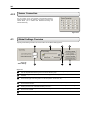
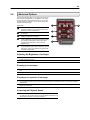
1.2
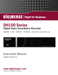
Front Panel Controls and LEDs
The front panel of HDDR unit contains the devices that will be commonly used for data removal,
retrieval, and backup replacement. The most common components and buttons are shown
below:
1
2
1
5
Figure 1.2
1
Hard Drive Activity LED Display
2
Power LED Display
3
CDR-W Drive
4
CDR-W Open Tray Button
4
3
6
7
5
6
7
Cooling Fan Air Intake
ON/OFF Power Switch
3.5” Floppy Disk Drive
Figure 1.2
17
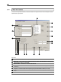
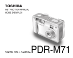
1.3
Rear Panel Connectors
The rear panel of the HDDR unit contains virtually all of the connectors you will be using. Below
is a diagram that outlines the location and description of each connector:
2
1
3
Figure 1.3
4
5
6
7
8
9
10 11
13
16
19
14
12
Figure 1.3
1
RG 35 Connector for Camera Input
and Looping Outputs
2
75 Ohm Switch
3
Control Alarm Outputs / Sensor Inputs
4
AC Power Adapter
5
110V / 220V Switch
6
PS/2 Mouse Input
7
PS/2 Keyboard Input
8
USB Ports
9
DB-9 Serial Input 2
10
LPT Parallel Printer Port
15
17 18
11
DB-9 Serial Input 2
12
13
14
15
16
17
18
19
DB-15 Serial Port
Audio Speaker Out
Audio Line In
Audio Microphone In
DB-15 SVGA Monitor Output
RS-422 Interface
RCA Video OUT
RJ-45 Network Jack
18
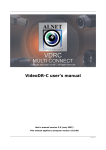
1.4
Serial Number
1
2
Figure 1.4
Figure 1.4
1)
1
2)
2
Part Number – You can find your model number located on the side of the HDDR unit as
shown in Figure 1.4.
Serial Number – You can find your serial number located on the side of the HDDR unit a
shown in Figure 1.4.
19
C H A P T E R
Getting Started
This chapter includes the following information:
Included Components
Setting up your HDDR Hardware
Optional Components
20
2.1
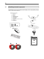
Identifying included components
Surveillix® HDDRs come with a mouse, keyboard and selected software and cables. Identify the following components
to make sure everything has been properly included with your new HDDR unit. If any of the following items are missing,
contact your dealer to arrange a replacement.
Included Component List:
1.
2.
3.
4.
5.
6.
7.
8.
9.
10.
HDDR Unit
Mouse
Keyboard
HDDR Software Disc
HDDR Repair Disc
Power Adapter
PTZ Adapter
Rackmount Attachments with Screws
HDDR Key
HDDR Manual
6
7
1
8
2
9
3
10
5
4
Manual
21
2.2
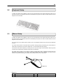
Keyboard Setup
To attach the keyboard to the HDDR unit, plug the end of the Keyboard into the keyboard PS/2 Port located on the
back of the machine. The keyboard PS/2 Port can be identified by the purple color. Refer to the Rear Panel Connectors
diagram for more information.
2.3
Mouse Setup
To attach the keyboard to the HDDR unit, plug the end of the Keyboard into the keyboard PS/2 Port located on the
back of the machine. The keyboard PS/2 Port can be identified by the purple color. Refer to the Rear Panel Connectors
diagram for more information.
The mouse uses a cursor called a pointer. Pointers come in many different shapes but are most commonly shaped like
an arrow.
Your mouse has two buttons: a left button and a right button. Quickly pressing and releasing one of these buttons is
called clicking. Sometimes you will need to double-click – or click the same button twice quickly.
In this manual, click means to position your mouse point on an icon and to single click the left button. When a right click
is required, this is stated clearly. Double-click also refers to the left button.
The ratchet wheel in between the two buttons is added to provide easier scrolling capability. By simply moving the
wheel with your index finger, you can quickly move through multiple pages, line, or windows. The wheel may also
function as a third button allowing you to quickly click or double-click an icon or a selected item.
2
3
1
Figure 2.3
Figure 2.3
1
Scroll button / Third Button
2
Left Button
3
Right Button
22
2.4
Monitor Setup
Attach the Monitor to the Rear of the HDDR unit using the VGA cable supplied by the Monitor Manufacturer. Refer to
your monitor manual for detailed information on how to setup and use it.
NOTE: The monitor you use must be capable of having a screen resolution of 1024 x 768 and display colors of at least 24 Bit
2.5
Power Setup
Attach the AC power cable to the rear of the HDDR Unit. See Rear Panel Connectors for more information.
WARNING: To reduce the risk of electrical shock or damage to the equipment:
•
•
•
2.6
Do not disable the power grounding plug. The grounding plug is an important safety feature.
Plug the power cord into a grounded (earthed) electrical outlet that is easily accessible at all times.
Disconnect the power from the computer by unplugging the power cord either from the electrical outlet or the
computer.
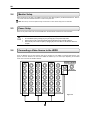
Connecting a Video Source to the HDDR
There are different types of Video Sources that can be plugged into your HDDR unit including DVD players, VHS
players, and CCTV Cameras. The back of the HDDR unit contains up to 16 video inputs depending on the HDDR
model. The connectors use the BNC standard.
Figure 2.6
1
23
Figure 2.6
1
2.7
Video Inputs – The Video inputs are RG-53 BNC connectors. Simply plug one end into your video source (DVD,
Camera, etc.) and plug the other end into the desired BNC input on the HDDR unit.
Optional Components
To fully utilize your HDDR unit’s potential, several optional Surveillix components are listed below. Contact your dealer
for more information.
1)
2)
3)
4)
5)
6)
Extra Video Storage Hard Drive – Each HDDR unit has a virtually unlimited storage potential. By adding
additional Video Data Hard Drives you can extend the amount of Video Data your HDDR system can store before
overwriting older data.
100MB / 250MB Zip Drive – Zip drives are an easy way to transfer small amounts of Video Data. Often times it is
all that is needed when delivering the extracted video to Law Enforcement.
DVD ROM Recordable Drive – DVD Recorders are an exceptional way to store large amounts of Video Data
easily. Each DVD can store up to 5 Gigabytes of Video Data.
USB External Hard Drive – An easy way to extract large amounts of Video Data from the HDDR unit is to use an
USB External Hard Drive. This drive connects to the USB port on the HDDR unit and can be attached to any
computer with an USB port.
Fiber Network Interface Adapter – A Fiber Network Adapter is used in enterprise network environments where
large amounts of data are transferred across the LAN. If large groups of people are logging in remotely across the
LAN, the Fiber adapter will speed the data transfer.
Gigabit 10/100/1000 Network Interface Adapter – A Gigabit Ethernet adapter can transfer data up to 10 times
faster than standard fast Ethernet which comes standard with the HDDR unit. This speed can be helpful if many
people access the HDDR remotely.
24
C H A P T E R
HDDR Basics
This chapter includes the following information:
•
•
•
Turning the HDDR on and off
Becoming familiar with the Display screen
Defining Screen Divisions
25
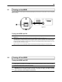
3.1
Turning on the HDDR
Once the hardware com been properly connected (See Chapter 2) it is time to turn on the power. To turn on the power
follow these steps:
1
Figure 3.1
Turning the HDDR unit ON
1)
2)
Turn on the monitor and any external peripherals (ex. Printers, External Storage Devices, etc.) connected to the
HDDR unit.
Turn on the main power switch located on the front of the HDDR unit as shown in Figure 3.1.
The HDDR will run a series of self-tests. After two or three minutes a series of messages may be displayed as the
various hardware and software subsystems are activated. Under normal circumstances you should not be asked
to respond to these messages. If you are asked to respond to the messages (adding a Printer, Monitor, etc for the
first time) follow the instructions carefully.
After this finishes, the Surveillix HDDR software should load automatically and bring you to the main screen.
3.2
Turning off the HDDR
Turning the HDDR unit OFF
1)
To turn off the HDDR unit, select the Exit button from the main screen. This will prompt you whether you wish to
exit the program or not. Select yes. The HDDR unit will shut itself off automatically once this is done. The HDDR
unit may take several minutes to shut down completely.
CAUTION: Always be sure to follow the proper procedures when turning off the power to the HDDR unit. NEVER
disconnect the power to the HDDR unit while it is still running or in the process of shutting down. Doing so can cause
data loss, file corruption, system instability and hardware failure.
26
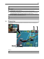
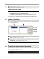
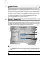
3.3
Display Screen
Each time the HDDR is restarted, the program defaults to the Display screen. The following diagram outlines the
buttons and features used on the Display screen. You should become familiar with these options as this is the screen
that will be displayed the majority of the time.
1
2
3
4
5
6
7
8
9
15
14
13
10
12
11
Figure 3.3
Figure 3.3
1
3
Exit Button – The exit button brings up several options, including Shut Down, Restart, Log On, Log Off and
Restart in Windows Mode.
Log In / Log Out – This button Logs the current user off and allows you to Log in using a different user
account.
Setup – This Brings up the setup menu from which all customizable settings can be edited.
4
PTZ – Opens the PAN / TILT options for controlling PTZ enabled Cameras.
5
Backup Button – Brings up the Backup options.
6
Search Button – Displays search features that allow you to search through previously recorded video.
7
Current User – Displays the name of the user currently logged in to the HDDR.
8
Network Information – Displays whether a Remote User is logged in.
2
27
9
Remote User Display – Displays the users connected to the HDDR.
10
Instant Replay – This button is a shortcut that instantly jumps into Search Mode and begins playing the video
backwards.
Date/Time – Displays the current time and date. This date and time is stamped into the recorded video and is
displayed whenever the video is played back.
Sensor Status Bar – Displays the Sensor status for each camera that is setup to use Sensors.
11
12
14
Control Output Status and Activation Bar – The Relay buttons fire the Output Relays. The Output Relays
can be hooked up to external alarms, set to trigger an audio alarm, send a phone call, etc.
Screen Division Buttons – The Screen Division buttons allow you to view one or more sets of cameras at a
time. They are organized in several different groups such as.
Full Screen – Displays the video full screen.
15
Loop – Pressing the Loop button rotates through the Screen Divisions.
13
Camera View
3.4
The Cameral status for each camera is displayed next to the Camera number (or name) on the Video Display Area.
The following are
2
1
IIIN
N
S
T
A
N
T
NS
ST
TA
AN
NT
T
3
Figure 3.4
Figure 3.4
1
Camera Number and Name – Displays the camera number and the custom name given to the camera.
28
3.5
2
Recording Status – Displays the current recording status of the camera using symbols. (See Section 3.5)
3
Special Recording – Displays text relating to the type of recording that is occurring. (See Section 3.5)
Recording Status Indicator
The Camera status for each camera is displayed next to the Camera number (or name) on the Video Display Area. The
following are the different states for each camera:
Recording – A red light is displayed when the camera is currently being recorded to the HDDR unit.
Motion Detection – A blue light is displayed when a camera (set up for motion detection) detects motion.
Display – This is displayed when the camera is currently not being recorded to the HDDR unit.
There are several different types of HDDR ‘Special Recording’. When this happens text is displayed on the camera
indicating what kind it is. These are as follows:
SENSOR – Sensor is displayed when a sensor, associated with a given camera, is activated.
INSTANT – Instant is displayed when a user activates the instant recording option.
3.6
Screen Division Menu
The Screen Division menu allows you to view cameras full screen by rotating one by one, four by four, eight by eight or
by viewing four, eight or 16 at a time. The button options are shown below.
1st Four Cameras View – Displays cameras 1-8 in the Video Display Area. To return to a different MultiCamera View, select a different Screen Division option from the Camera View Option.
2nd Four Cameras View – Displays cameras 5-8 in the Video Display Area. To return to a different MultiCamera View, select a different Screen Division option from the Camera View Option.
3rd Four Cameras View – Displays cameras 9-12 in the Video Display Area. To return to a different MultiCamera View, select a different Screen Division option from the Camera View Option.
4th Four Cameras View – Displays cameras 13-16 in the Video Display Area. To return to a different MultiCamera View, select a different Screen Division option from the Camera View Option.
5rd Four Cameras View – Displays cameras 17-20 in the Video Display Area. To return to a different MultiCamera View, select a different Screen Division option from the Screen Division menu.
6th Four Cameras View – Displays cameras 21-24 in the Video Display Area. To return to a different MultiCamera View, select a different Screen Division option from the Screen Division menu.
7rd Four Cameras View – Displays cameras 25-28 in the Video Display Area. To return to a different MultiCamera View, select a different Screen Division option from the Screen Division menu.
8th Four Cameras View – Displays cameras 29-32 in the Video Display Area. To return to a different MultiCamera View, select a different Screen Division option from the Screen Division menu.
1st Eight Cameras View – Displays cameras 1-8 in the Video Display Area. To return to a different MultiCamera View, select a different Screen Division option from the Screen Division menu.
2nd Eight Cameras View – Displays cameras 9-16 in the Video Display Area. To return to a different MultiCamera View, select a different Screen Division option from the Screen Division menu.
29
1st Sixteen Cameras View – Displays cameras 1-8 in the Video Display Area. To return to a different MultiCamera View, select a different Screen Division option from the Screen Division menu.
2nd Sixteen Camera View – Displays cameras 9-16 in the Video Display Area. To return to a different MultiCamera View, select a different Screen Division option from the Screen Division menu.
32 Camera View – Displays cameras 1-32 in the Video Display Area. To return to a different Multi-Camera
View, select a different Camera View Option.
Multi-Camera View – Displays a group of cameras within the Video Display Area.
Multi-Camera View – Displays a group of cameras within the Video Display Area.
Multi-Camera View – Displays a group of cameras within the Video Display Area.
Multi-Camera View – Displays a group of cameras within the Video Display Area.
Multi-Camera View – Displays a group of cameras within the Video Display Area.
Full Screen – The Full Screen Option allows you to view the Video Display Area using the entire viewable area
on the monitor. When this is selected, no menu options are visible.
You can activate the Full Screen Option by clicking on the Full Screen Button within the Screen Division Menu.
You can deactivate it by pressing the Esc key (on the keyboard).
Loop – Pressing the Loop button rotates through the Screen Divisions.
30
C H A P T E R
Setup Options
This chapter includes the following information:
•
•
•
•
•
•
•
•
Setup Overview
Channels
Color
Schedule
Speed
Motion Detect
Password
Pan/Tilt
31
4.1
Setup Overview
The Setup options allow you to optimize your HDDR unit by adjusting things like camera names, reboot schedules,
recording schedules and more. It is extremely important that you setup your HDDR correctly for several reasons.
•
•
•
•
•
4.1.1
Recording Schedules – By optimizing the recording schedule you can increase the amount of pertinent
recorded video that is saved on the HDDR and keep it longer. You can optimize the type of recording done
by adding motion detection to this as well, again increasing the amount of useful video.
HDDR health – By setting up routine reboot schedules you can ensure that the HDDR unit remains in perfect
working order.
HDDR Access – By setting up the access passwords you can tightly control the types of access an individual
may have. This ensures the security and integrity of the HDDR unit.
Camera Naming – By naming each camera you can easily identify the location and any other pertinent
information that may be helpful simply by viewing it on the Video Display Area.
Adjusting Camera Color – By adjusting each cameras color settings you can optimize the clarity and detail
that is recorded.
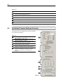
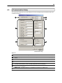
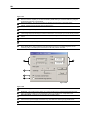
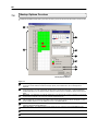
Setup Screen Overview
1
6
2
3
Figure 4.1.1
5
4
32
Figure 4.1.1
1
Setup Options – Allows you to toggle between different setup screens.
2
3
Individual Camera Settings – Displays the options for adjusting a camera’s Color Settings, Sensor
Connections, Motion Detection Zones, etc.
Apply – Saves settings.
4
Close – Exits setup.
5
Global Settings – A series of setup options that affect all cameras.
6
Camera Selector – Selects the current camera to be edited.
Individual Camera Settings Overview
4.2
Several Setup options are available for each camera individually.
These options are listed below.
Figure 4.2
1
2
3
4
5
6
Camera Information – Allows you to adjust the name
and color settings for each camera.
Motion Settings – Displays options for editing each
camera’s Motion Detection settings.
Sensor Connections – Allows you to attach one or
more sensor connections to each camera.
Pre-Alarm – Allows you to record a section of video
just prior to Motion or Sensor activation.
All Camera Setting– Selecting this option copies the
settings for the selected camera to all the cameras.
Pan/Tilt Detail Setup– These options setup a PTZ
camera to the HDDR unit and allow you to create
Presets and Tours. (Refer to PTZ Chapter in this
manual)
1
2
3
4
5
6
Figure 4.2
33
4.2.1
Camera Information
Several Setup options are available for each camera individually.
These options are listed below.
Figure 4.2.1
1
1
Name – Allows you to specify a name for each camera.
2
Bright – Adjusts the Brightness of the selected camera.
3
Hue – Adjusts the Hue of the selected camera.
4
4
Contrast – Adjusts the Contrast of the selected
camera.
Adjust Default – Adjust the color settings for the
selected camera back to the System default.
Adjust All Default – Adjusts the color settings for ALL
cameras to the System default.
5
5
6
2
3
6
Figure 4.2.1
Motion Setting
4.2.2
The HDDR unit allows you to adjust several different Motion Settings.
Figure 4.2.2
1
2
3
4
5
Beep on Detect – When motion is detected an alarm is
sounded.
Full Screen Pop-Up – When Motion is detected, the
camera is brought up in full screen mode.
Alarm Output – Enables the Alarm Output. The Alarm
Output is always defaulted to Control Output #16.
Control Output #16 is System designated default for an
external alarm.
Sensitivity – Adjusts the sensitivity within the
designated Motion Area.
Clear Motion Area – Clears all Motion Areas for the
selected camera.
1
2
3
4
5
Figure 4.2.2
4.2.2.1 Creating a Motion Area
Creating a Motion Area
1)
2)
Place the mouse pointer at the upper left hand corner of the
area you want to designate, press and hold down the left
mouse button, drag the mouse. Let go of the button when the
Motion Area is the size you want it to be.
Continue creating as many Motion Areas as you wish. You can
resize them and move them by dragging the sides and corners
of the Motion Area.
34
Sensor Connection
4.2.3
You can connect one or more Sensors to the selected camera by
checking the box next to the sensor(s). Connecting a sensor to the
camera allows you to activate both Standard Recording and
Intensive Recording.
Figure 4.2.3
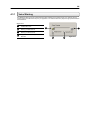
Global Settings Overview
4.3
Adjusting Global Settings will affect all cameras. Below are the Global Settings options.
1
Figure 4.3
Global Settings
7
2
3
4
6
5
Figure 4.3
1
2
3
4
5
6
7
Auto Switching Time(s) – When the Loop button is activated, the Auto Switching Time specifies the amount of
time that elapses before switching to the next Screen Division group.
Voice Warning – Allows you to use an audible warning (.wav Sound Clip) for when Motion or Sensors are
activated.
System Schedule – Opens the System Schedule window which allows you to specify the time and dates to
record and the type of recording which is to be done (Motion, Continuous, etc).
Recording Schedule – Opens the Recoding Schedule window which allows you to adjust the Frames per
Second for each camera.
Communication Setup – Opens the Communication Setup window which contains options and settings for
allowing remote access, Internet Broadcasting and more.
Intensive Recording – Opens the Intensive Recording window which allows you to specify the Frames per
Second to be recorded.
Motion Index Interval – Specifies the amount of time to record once Motion has been activated.
35
4.3.1
Voice Warning
The HDDR unit allows you to play a sound file when either a Motion event or Sensor event occur. This file can be a
custom created sound file that is unique to your application. The selected WAV file is played through speakers attached
to the HDDR unit.
Figure 4.3.1
1
2
3
4
Open – Allows you to select eh location of
the WAV file to use.
Motion Event – Enables the Voice
Warning on Motion Events.
Sensor Event – – Enables the Voice
Warning on Sensor Events.
Play Selected WAV – Plays the selected
WAV file.
1
4
2
3
Figure 4.3.1
36
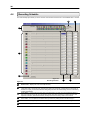
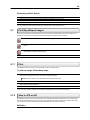
4.4
Recording Schedule
The Channel Setup option allows you to turn cameras on/off as well as rename them to an identifiable name or number.
1
2
3
4
5
Figure 4.4
Recording Schedule
6
7
Figure 4.4
1
Video Format – Displays the Video Format (NTSC/PAL).
2
Sensitivity – The Sensitivity adjusts the rate at which the Keyframe refreshes. This option directly affects the
codec being used to record the video. Adjusting this setting can have drastic negative affects on the quality of
the video. It is highly recommended that this setting always be left at the default setting unless so instructed by
a system administrator.
Frame Status – Displays the layout and order of the frames being recorded. The Frame Status represents a
One Second period of time with 240 colored blocks inside. Each block represents one frame and each color
represents a camera. (See Camera Number) The layout shows the recording order for each second.
Camera Number – The cameras are given different colors to help distinguish themselves when viewing the
Frame Status. You can adjust the recorded Frames per Second by sliding the bar to the left and right.
Set Default – Selecting this option resets all camera Frames and resolutions to the default settings.
3
4
5
6
Resolution – Displays the available Resolution options.
37
Quality – This settings affects the quality of the video. Increasing the quality of the camera can reduce the
amount of pixilation within the image considerably, but also increases the file size.
7
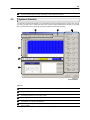
4.5
Systems Schedule
The Recording Schedule Window allows you to create different recording schedules based on the day, time, and type
of recording you wish to use. In addition this window also contains the System Restart options that allow you to perform
basic system maintenance by automatically scheduling the HDDR to restart itself periodically.
1
2
3
4
5
6
Figure 4.5
System Schedule
Figure 4.5
1
Day of the Week – Selects the day of the week for the schedule being made.
2
Single Selection Mode – Selects all days of the week at once.
3
System Restart Time – Displays the restart options. The HDDR unit allows you to specify the unit to be
automatically restarted one or more days a week.
Recording Schedule Window – Displays and allows you to edit the current Recording Schedule.
4
5
6
Recording Mode – Selects the Recording Mode. The Recording Modes are ‘NO RECORDING’ ‘CONTINUOUS
RECORDING’ and ‘MOTION RECORDING’
Special Day Recording – Allows you to create special recording schedules for specific days. You can create
as many special.
38
4.5.1
Creating a Recording Schedule
Creating a Recording Schedule
1)
2)
Select a day to begin creating the schedule for -or- Select the SINGLE SELECTION MODE button to create the
schedule for all the days of the week at once.
Highlight the time-blocks within the Recording Schedule Window for the camera(s) you wish to schedule. Once the
desired Time-Blocks are highlighted, press a RECORDING MODE button.
The Time-Blocks should now appear Blue for Motion, Yellow for Continuous and White for No Recording
Leave Cameras that will be recording with Sensor Detection set to ‘No Recording’ for the specified time block(s).
4.6
Special Day Schedule
You can create days that have a unique recording schedule. You may wish to create these on days that are ‘not typical’
such as Holidays, Special Events, etc.
1
2
3
4
5
Figure 4.6
Figure 4.6
1
Calendar – Displays the current day in a red circle.
2
Special Day Schedules – Displays the current saved.
3
4
Special Day (Enter/Exit Edit Mode) – Enters / Exits the Special Day Mode. Once in Special Day Mode you
can create, edit and delete Special Days.
Delete Special Day – Deletes the selected Special Day Schedule.
5
Save Special Day – Saves the selected Special Day Schedule.
4.6.1
Creating and Editing a ‘Special Day’ Schedule
Creating a ‘Special Day’ Schedule
1)
2)
Press the ‘NORMAL DAY MODE’ button to enable the ‘SPECIAL DAY MODE’.
Select a day from the Calendar by left clicking on the day with the mouse. The selected day should appear in a
blue highlighted oval.
39
3)
4)
Highlight the time-blocks within the Recording Schedule Window for the camera(s) you wish to schedule. Once the
desired Time-Blocks are highlighted, press a RECORDING MODE button.
When you have finished creating the schedule press the ‘SAVE SPECIAL DAY’ button. The special day should
now appear as a date within the Special Day Schedules.
Deleting a ‘Special Day’ Schedule
5)
4.7
Select a Special Day from the Special Day Schedules List and press the ‘DELETE SPECIAL DAY’ button.
System Restart Time
Allowing the HDDR unit to automatically restart itself can be an important part of basic maintenance. When the HDDR
unit restarts, memory, cache, and other HDDR systems are flushed and renewed. This creates an overall better
functioning system.
1
4
2
3
Figure 4.7
Figure 4.7
1
Day of the Week – Displays the Day for the settings being adjusted.
2
3
Enable – Enables the HDDR to shut down the computer at the time specified. This option alone does NOT
restart the HDDR, it just simply turns it off.
Restart / OFF – Enables the HDDR to restart itself once it has been shut down.
4
Time – Specifies the time to Shut Down or Restart the HDDR unit.
Intensive Recording Overview
4.8
The Intensive Recording Option allows you to increase the Frames Per Second and the resolution of any camera
recording using sensor activation. When the intensive recording is activated, the resolution of the remaining cameras is
immediately reduced to 360x240 and the Frames per second to a user specified level. This is done to guarantee that
the Frames Per Second and Resolution will be set correctly and not exceed the HDDR limitation.
1
4
2
5
3
6
Figure 4.8
40
Figure 4.8
1
Intensive Channel – Adjusts the Frame Rate for the Intensive Channel.
2
3
Non-Intensive Channel – Adjusts the Frame Rates for the Non-intensive Channels (the channels will drop their
current settings and be forced to use this setting.
Holding Duration – Adjusts the amount of time to hold the Intensive Recording active.
4
Intensive Channel Resolution – Adjusts the Resolution for the Intensive Channel.
5
Non-Intensive Channel Resolution –The HDDR automatically adjusts the Non-Intensive Channels down to
the system default. This setting cannot be changed.
Intensive On-Sensor – This setting enables the association of Intensive Recording to sensors.
6
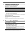
4.8.1
How to use Intensive Recording
The Intensive Recording option is setup as an ‘All or Nothing’. This means that once enabled (associated with sensors),
all cameras that are associated with sensors will activate the Intensive Recording.
To activate the Intensive Recording option, follow these steps.
Activating Intensive Recording
1)
2)
3)
4)
5)
6)
Inside Setup, select the camera you wish to use and then enable the appropriate sensor (See Section 4.2.3) you
wish to associate to it.
Open the Intensive Recording Options. Enable the Intensive-On-Sensor option and then select the desired
Frames Per Second for both the Intensive and Non-Intensive Channels. You can also adjust the Resolution and
the holding duration for the Intensive Channel.
Close the Intensive Recording window by selecting the APPLY button.
Open the Sensors and Outputs window.
Enable the sensor you associated with the Intensive Recording by placing a check in the box next to it.
Press the APPLY button and exit out of setup
41
4.9
Communication Setup
The Communication Setup allows you to adjust settings such as Ports, Emergency Agent IP Addresses, IDVR Users
and NDMS identification.
4
1
5
2
6
3
7
Figure 4.9
Communication Setup
Figure 4.9
1
Disable Remote Control – This setting enables or disables access to the HDDR from remote connections.
2
3
Network Setup – Specifies the Ports to use when transferring data, as well as defines the Emergency Agent IP
Address.
Web Function – Enables the use of the IDVR Web interface as well as defines users who can access it.
4
Quality – Adjusts the resolution quality when transferring video to a remote client.
5
Resolution – Adjusts the resolution of the images being sent to remote clients. By setting the resolution low,
the images will be sent faster, however, the image quality will be reduced considerably.
PPP Setup (Emergency) – Defines the modem and PPP information to dial to a remote client when the
Emergency Agent is activated.
NDMS Control – This option enables the use of NDMS and associates it to an NDMS group.
6
7
42
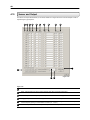
4.10
Sensor and Output
The Sensor and Output Window allows you to enable, disable and configure Sensors and Control Outputs as well as
adjust Emergency Agent options.
1 2
3
4
5
6
7
8
9
10
14
11
12
13
Figure 4.10
Figure 4.10
1
Use – Enables/Disables the Sensor for use.
2
Type – Selects whether the Sensor will be Normally Open (NO) or Normally Closed (NC).
3
Record – Specifies the time period (in seconds) to record once the Sensor is tripped.
4
Delay(s) – Adjusts the amount of time to ignore the sensor if it is continuously activated.
5
Output – Selects the Control Output to activate once the Sensor has been tripped. You can select multiple
Control Outputs by placing a comma between numbers. (ex. 1,2,6,13)
Duration – Adjusts the amount of time (in seconds) that the Control Output will remain activated.
6
43
7
8
Use by Time – This option Enables/Disables the Use by Time feature. When activated the Use by Time feature
allows you to specify a time period that the Control output will be operational. For example you could disable the
control output during work hours so that alarms will not go off when a door is opened and a sensor is tripped.
Name – This option allows you to assign a meaningful name the Control Output. (ex. Warehouse Siren)
9
Auto ON – The time at which the Control Output will be available for use.
10
Auto OFF – The time at which the Control Output will be disabled and not available for use.
11
Sensor Number for Alarm Output (Siren) – Associates the selected Sensor to the Siren (Control Output #16).
When the sensor is tripped the Siren is immediately activated.
Transmission Sensor – Specifies which sensors will activate the Emergency Agent software. You can specify
more than one sensor by separating them with commas. (ex. 2,4,13,15,16)
Transmission Duration – Specifies the amount of time (in seconds) to transmit the video in the Emergency
Agent Software.
ATM/POS Setup – This option allows you to change the settings that connect an ATM /POS device to the
HDDR.
12
13
14
44
4.11
Site Information
The Sensor and Output Window allows you to enable, disable and configure Sensors and Control Outputs as well as
adjust Emergency Agent options.
1
17
2
16
3
15
14
4
13
12
Figure 4.11
5 6 7
8
9
10
11
Figure 4.11
1
Drive Information – Displays the Total Space and Free Space of the Drives installed in the DVR.
2
Site Code – A user-specified unique identification name that is used by other DVR software to connect to the
DVR. (Remote, Emergency Agent, NDMS)
Site Information – Displays misc. information about the DVR.
3
4
5
6
7
Display Sensor Status BAR – Enables/Disables the Sensor Status Bar on the Main Display Screen. (See
section 3.3)
Display Motion Detection Area Box – Selects the Control Output to activate once the Sensor has been
tripped. You can select multiple Control Outputs by placing a comma between numbers. (ex. 1,2,6,13)
Display Control Status Bar – Enables/Disables Control Status Bar on the Main Display Screen. (See section
3.3)
Dual Monitor Mode – This option is only used when DUO-Mon monitors are used on the DVR.
45
8
OSD Font Size – This option allows you to adjust the On Screen Display Font size for cameras.
9
OSD Bold – This option makes the OSD Font Bold.
10
Log Viewer – This option opens the Log Viewer Window which allows you to view the DVR System Logs.
11
12
User Management – This option opens the User Management Window. User Management allows you to
create, edit and delete DVR user accounts.
Tech Support – Displays the Tech Support Phone Number.
13
Contact Number – Displays a user specified Contact Phone Number.
14
This Product Licensed to – Displays the licensing information for the DVR unit.
15
System – Displays the Processor and Memory that are installed inside the DVR.
16
Computer – Displays the Operating System version installed on the DVR.
17
Site Version – Displays the DVR Software version.
4.12
Log Viewer
The Log Viewer displays detailed information about the DVR, including Shut Down and Restart information, User
Logins and Recording problems and failures. This can be a valuable tool to Administrators.
1
2
3
4
Figure 4.12
Figure 4.12
1
Calendar – Displays the days with Log information in a bold format
2
3
System Log – Displays the Hardware Log file information which includes Scan Disks, and system recording
successes and failures.
Event Log – Displays information pertaining to User Logins, DVR reboots and other related information.
4
Export – Allows the log files to be exported in week increments.
46
4.13
User Management
The User Management Console allows you to create, edit, and delete user accounts. Each user account can be
assigned different privileges that limit their usage of the DVR system. Users can be given administrator privileges by
enabling all rights, however only the true administrator account can log into the User management Console.
Figure 4.13
1
2
3
User Information – Enter the User
Information, and Password.
Permission – Allows you to specify the types
of permissions a user may perform on the
DVR.
Hidden Camera – The Hidden Camera
feature allows an administrator to hide certain
cameras from a user. The user will not be
able to view the cameras in Live Mode.
1
2
3
Figure 4.13
4.13.1
Changing the Administrator Password
Changing the Administrator Password
1)
2)
Inside Setup, open the user management console. An administrator login will appear with a ‘Change Password’
button near the bottom right
Select the button, enter the new password and press OK to finish.
47
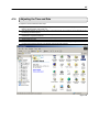
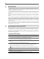
Adjusting the Time and Date
4.14
To adjust the Time and Date follow these steps:
1)
2)
3)
4)
5)
6)
Begin by exiting to Windows. Do this by pressing the EXIT button from the Main Display Screen and selecting
Restart in Windows Mode. (See Section 3.3)
Open Windows Explorer. Do this by right-clicking on the My Computer Icon (located on the top left hand corner of
the Desktop) and select Explore.
Double click on CONTROL PANEL to open it. If you do not see CONTROL PANEL listed, double-click MY
COMPUTER to expand the folder tree.
Double Click on DATE/TIME inside Control Panel. (See Figure 4.10a)
Adjust the Date and Time.
When finished, close all open windows and restart the HDDR unit. DO this by pressing the START button
(Located on the lower left hand side of the Desktop) and selecting SHUT DOWN.
Figure 4.14
48
C H A P T E R
Search Options
This chapter includes the following information:
•
•
•
•
•
•
•
•
•
Setup Overview
Channels
Color
Schedule
Speed
Motion Detect
Password
Pan/Tilt
Quit to Explorer
49
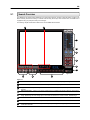
5.1
Search Overview
The HDDR unit has several options that allow you to easily search through, and find, a particular section of video. From
Motion indexing and Sensor indexing to calendar views showing which days have recorded video, the HDDR unit is
equipped to help you quickly find what you’re looking for.
The following chapter will describe in detail how to use the HDDR Search features.
11
10
1
2
3
4
5
6
Figure 5.1
9
8
7
Figure 5.1
1
Hour / Minute Control Bar – Allows you to select the hour and minute by adjusting the sliding bar.
2
Select Date – Opens a calendar window and allows you to select a day to perform a search on.
3
Play Controls – The options allow you to view selected video Frame by Frame, Normal Speed, and Fast
Forward.
Advanced Controls – Allows you to perform operations such as adjusting the speed, brightness, and zooming.
4
5
6
Clean Image – Often time’s extensive motion can create a ‘digital blur’ that can interfere with the quality of an
image. By selecting the Clean Image option, two frames are interwoven to create a smooth, detailed image.
Return to Main – The Return to Main button exits out of search and returns you to the Main Display Screen.
7
Camera Select – Allows you to enable (or disable) selected cameras to perform searches on.
8
Print/Open/Export Options – These options allow you to print images, save single images to disk and load
saved video from disk.
50
9
10
11
5.2
Search Options – The search options are a set of functions that allow you to easily find the specific video clips
you want and to export them to a usable format
Screen Division Buttons – The Screen Division buttons allow you to view one or more sets of cameras at a
time. They are organized in several different groups such as.
Search Date and Time – Displays the Date and Time of the video being played.
Play Controls
The Play Controls allow you to play the video Frame by Frame, Normal Speed, and Reverse.
Figure 5.3
1
2
3
4
5
6
7
5.3
Stop – This option stops any video that is currently
playing.
Play (Normal Speed) – This option plays the video at
normal speed.
Jump to End - This option when pressed jumps to the
end of the recorded video.
Play (Frame by Frame) – This option plays the video one
frame at a time (One frame each time the button is
pressed).
Play Reverse (Frame by Frame) – This option plays the
video one frame at a time in reverse (One frame each
time the button is pressed).
Jump to Beginning – This option when pressed jumps to
the beginning of the recorded video.
Play Reverse – This option plays the video at normal
speed in Reverse.
1
7
2
6
3
5
4
Figure 5.3
Hour / Minute Control Bar
The Hour/Minute Control Bar allows you to select the Hour and
Minute using an easiy-to-use slide bar. You can control the slide
bar not only by clicking and dragging the slider but also using the
Wheel on the Scroll Mouse.
1
3
Figure 5.3
1
2
3
4
Hour Selector – The Hour Selector displays the hours for
a given day 0 to 24. Move the Slide Bar Selector up and
down to select an hour.
Slide Bar Selector –The Slide Bar can be moved up and
down to select the hour and minute.
TIP: By using the Wheel on the mouse, you can easily
move the Slide Bar Selector up and down. Simply click on
the Slide Bar Selector with the Mouse and then begin
moving the Wheel up and down.
Minute Selector – The Minute Selector displays the
minutes for a selected hour 0 to 60.
Select Date – Opens a calendar window and allows you
to select a day to perform a search on.
2
4
Figure 5.3
51
5.4
Advanced Options
The Advanced Controls allow you to get the most out of your
serach. Using the Brightness you can brighten up an image
to get more detail. Using the Zoom feature you can not only
bring the image up full screen, but you can also Zoom into a
particular area of the image.
Figure 5.4a
1
2
3
4
5
Frame Skip – This option skips the selected number
of frames on playback. This causes the video to be
played back at an accelerated rate.
Zoom – The Zoom Selector allows you to Zoom in
on an image.
Brightness – The Brightness selector allows you to
adjust the Brightness of an image.
Clean Image – Often time’s extensive motion can
create a ‘digital blur’ that can interfere with the quality
of an image. By selecting the Clean Image option,
two frames are interwoven to create a smooth,
detailed image.
Frame Delay – This option pauses on each frame for
the specified time. When used in conjunction with the
‘Skip’ option, video can be played back quickly while
still easily distinguishable.
1
5
2
3
4
Figure 5.4a
Adjusting the Brightness of an Image
1)
2)
Select a single image to adjust by double-clicking the left mouse button on the desired image. You cannot adjust
multiple images at one time.
Using the Bright Slide Bar, move the bar to the right or the left. To reset the Brightness press the Reset Button
Zooming in on an image
1)
2)
Select a single image to adjust by double-clicking the left mouse button. You cannot adjust multiple images at one
time.
Using the Zoom Slide Bar, move the bar to the right or the left. To reset the Brightness press the Reset Button.
Zooming in on a portion of an image
3)
4)
Using the Mouse Pointer, point to an area on the image where you would like to zoom in on and press the RightMouse Button.
Keep pressing the Right-Mouse Button to zoom in further. After a certain number of clicks, the image will revert
back to its original size.
Increasing the Playback Speed
1)
Increase the speed of the video by increasing the Skip amount. Do this
by clicking the Up and Down Arrows on the Skip Button (See Section 5.4).
The maximum Skip rate is 30. Normal speed is 0
52
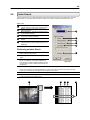
Clean Image
1)
The HDDR unit is capable of recording video using one of three different resolutions. When using the 720 x 480
resolution, two fields are mixed. Because of the timing gap between the two fields, according to the standardized
image rules, a little afterimage might occur to high speed moving images. The Surveillix® HDDR unit allows you
to remove this by pressing the CLEAN IMAGE button.
The images below demonstrate the filtered screen.
Figure 5.4b
Filtering Display playback
5.5
Search Options Overview
The Search Options allow you to find what you want quickly, enhance the image quality, and export the video or images
in a number of ways.
Index Search – This option allows you to perform a search based on Motion detection, Sensor activation,
and ATM/POS transactions. This search allows you to quickly narrow down large amounts of recorded
video based on that criterion.
Preview Search – The Preview search is a Search option that allows you to narrow down recorded video
in a 24 Hour period. It breaks down a single day into 24 images, one image for each hour of the day (The
images are taken from the first second of each hour). When an image is selected, the ‘hour’ chosen is then
broken down into 6 images, one image for every 10 minute increment. Finally when another image is
selected, 10 images are displayed, one for every minute within the 10 minute period. From this point, the
selected image can be applied to the Main Search.
Object Search – The Object Search allows you to specify a region on an image and perform a search
based on any motion that has occurred within that region.
5.6
Performing a Basic Search
There are several different types of searches that can be performed on the HDDR unit. The following section will cover
the most basic of these. This involves simply selecting the date, the time, the camera, and pressing play.
53
Performing a Basic Search
1)
2)
3)
4)
Begin by selecting a Date. Do this by opening the Calendar (See Section 5.3) and selecting a day.
Select a Time. Do this by adjusting the Hour and Minute Slide Bars (See Section 5.3).
Select a One or More Cameras (See Section 5.1).
Press the Play Button (See Section 5.2).
You can now play the Video Forwards, Backwards, and Frame by Frame (See Section 5.2).
5.7
Print/Open/Export Images
Once you find the video you are looking for you can Print it, Save it as a single image or Save it as a video clip. In
addition you can also open and play video that has previously been saved to a disc or hard drive.
Print – This option allows you to output a selected image to an attached printer.
Save – This option allows you to save a selected image as a JPG file or to save a video clip in an AVI
format.
Load – The Load Option allows you to search and view video that has been saved to media such as a
CDR, CDR-W, or External Hard Disk Drive.
5.7.1
Print
The HDDR unit allows you to print a recorded image to a local or network printer.
To print an image, follow these steps:
2)
From the Search Screen, stop on the image you wish to print. Make sure only one camera is selected by doubleclicking on the image you want. (Only one camera should be displayed)
NOTE: Only one camera can be selected at a time for this function to work.
3)
4)
5)
Select the Print Button. A Print Options window should appear.
Depending on the printer you are using you may have several printing options available to you. (Refer to your
printer manual for more information)
Press the ‘Print’ button to print the selected images.
If you do not have a printer installed, the ‘NO DEFAULT PRINTER INSTALLED’ message will appear.
5.7.2
Save to JPG or AVI
The HDDR unit allows you to export single images in the JPG file format and save video clips in an AVI format. Both
JPG and AVI file formats are the most commonly used graphical formats today. Virtually every computer offers some
type of support for these file formats and therefore make them the most ideal formats to use.
Definition
54
JPG: (Joint Photographic Experts Group) - The name of the committee that designed the photographic imagecompression standard. The format (.jpg) is optimized for compressing full-color or grayscale photographic images. JPG
images are 24-bit (16.7 million color) graphics.
AVI:
(Audio/visual interleaved) files are one of the more popular animated image formats in use today. They are
most often used for video playback, though they are also used for more simple things such as the Windows "file copy"
and "search" animations. AVI image data can be stored uncompressed, but it is typically compressed using a Windowssupplied or third party compression and decompression module called a codec.
1
Figure 5.10
1
2
3
4
5
JPG File – Saving to a JPG File allows you to
export a single image (or frame).
AVI File– Saving to an AVI File allows you to
save a video clip.
AVI Duration – Allows you to enter a duration
to record the AVI for (in seconds). Although 100
Seconds is the longest displayed, you can
manually enter a longer time.
Image Quality – Often times it is necessary to
reduce the overall size of an AVI file (When you
wish to email it to someone for example). You
can do this by reducing the image quality. By
reducing the image quality, the AVI video
appears more Pixilated. When size is not an
issue setting the quality to 100 is highly
recommended.
Export – The Export button begins the saving
process.
2
3
4
Figure 5.7.2
5
55
5.8
Index Search
Using the Index Search can greatly decrease the amount of time spent searching through saved video. The Index
Search allows you to perform a search based on criteria such as Sensor, Motion and Instant Record events.
Figure 5.11a
1
2
3
4
5
6
Select Camera – Allow you to either select a single
camera to search or select all the cameras at once.
Sensor – Searches by all sensor events on the
selected camera(s).
Motion Detection – Searches by all Motion events
on the selected camera(s).
Instant Record – Searches by all Instant Recording
events on the selected camera(s).
ATM/POS – Searches by ATM/POS Transaction
Number.
All Event – Searches on all events for the selected
camera(s) (Sensor, Motion, Instant Recording, and
ATM/POS).
1
2
3
4
5
Performing an Index Search
1)
Begin by Selecting the Index Search Button. The Index
Search Option Box should open.
2)
Select a single camera or select the ALL cameras
option.
3)
Select an Event to search on. (Sensor, Motion, Instant
Record, or ATM/POS). If you select ATM/POS you
have the option to enter a specific transaction number.
If no transaction number is entered all transaction will
be displayed.
Press the ‘OK’ Button. (It may take a minute or two to return the results)
4)
6
Figure 5.8a
If there are results found, they will be displayed in a column on the left side of the screen (See Figure 5.8b).
If there are no results found, ‘No Images Found’ will appear in the column.
5)
Once the results are displayed you can search through them by simply double-clicking any one of the results.
6)
Once you have found the image you are looking for, apply it to the Main Search by selecting the ‘Close’ Button
located at the bottom of the results column.
1
2
3
Figure 5.8b
4
5
56
Figure 5.11a
1
Image Display Area – The Image Display Area is where the Search Results Images are displayed.
2
Time – Displays the Time of the result.
3
Camera Number – Displays the Camera Number for the returned result.
4
Type – Displays the Event Type.
M Motion
S
Sensor
IR Instant Record
Search Results – Displays the results of the search. Each line represents a segment of video.
5
5.9
Preview Search
The Preview Search can be used in a number of circumstances to quickly find an exact moment where an event such
as a theft occurred. The Preview Search basically gives a 24 Hour visual overview of a single camera by separating a
24 hour period (1 day) into 24 images, one image for each hour of the day. The search can then be further narrowed
down into ten minute increments and one minute increments by simply selecting one of the images displayed.
1 Day (24 Hours) Total
1 Hour Increments
1
2
3
4
5
6
7
8
9
10
11
12
13
14
15
16
17
18
19
20
21
22
23
24
1
2
3
4
5
6
2
3
4
5
6
7
8
9
10
1
1 Hour Displayed
1 Minute Increments
10 Minutes Displayed
10 Minute Increments
1 Minute Increments
Figure 5.9
57
The images in Figure 5.9 show how the Preview Search functions. The first screen that appears has 24 images
displayed. Each image represents the first second of each hour. If there is no image recorded during that period then
nothing will be displayed. When an hour is selected (by double clicking on the image) then a new screen appears with 6
images. Each of these images represents a 10 minute segment of video. Once a 10 minute segment is selected (by
double-clicking on the image) the final screen appears which breaks down that 10 minute segment into 1 minute
increments (10 images).
Performing a Preview Search
1)
2)
3)
4)
5)
6)
7)
5.10
Begin by selecting a single camera. You can do this either by turning off all cameras but one, or by double clicking
a displayed image (it will then be the only image displayed on the screen)
Select the Preview Search Button.
24 Images should now be displayed. If there is no recorded video during a portion of the day then a ‘No
Image’ will be displayed where the image(s) should be.
Refine the search by selecting an image. Do this by double-clicking on the image.
6 Images should now be displayed. You can move back to the previous 24 image view by right clicking on an
image.
Refine the search by selecting an image. Do this by double-clicking on the image.
10 Images should now be displayed. You can move back to the previous 6 image view by right clicking on an
image.
To select a displayed 1 minute segment of video to begin playing it, simply double-click on the image.
A single image should now be displayed. You can move back to the previous 10 image view by right clicking
on an image.
You can now use the Play controls (See Section 5.2) to play the video.
To Apply the current image to the Main Search, that is, exit out of Preview search with the current image still
selected, simply deselect the Preview Search Button.
Object Search
The Object Search is a powerful Search utility that allows you to search a region on the video for any motion changes.
The Results are neatly displayed and allows you to view them quickly.
1
2
Figure 5.10a
9
8
7
6
5
4
3
58
Figure 5.10a
1
2
Search Results – The Search Results are displayed in this column. The results are listed by date and time.
When the search is complete you can view the results by double-clicking on one of the results or by using the
Up and Down arrow keys on the keyboard.
Search Information – The Search Information box displays brief information on the overall search.
3
Cancel – Selecting the Cancel button exits the Object Search.
4
Stop – The Stop option stops the current search.
5
7
Apply to Main Search – Apply to Main Search exits the Object Search but takes the selected result (the
current image displayed) and displays it inside the Main Search. From that point you can use the Play Controls.
Reload First Frame – This option reloads the initial Key Frame image, that is, the image used to start the
search.
Clear Selection – This option clears the current Motion Region Box from the Keyframe Image.
8
Start Search – This option Begins the search.
9
Motion Region Box – The Motion Region Box is the user defined area of the Keyframe image. You create the
Motion Region Box by clicking inside the image and dragging the mouse. The Motion Region Box can be
resized by pulling on the little square boxes located on the outer perimeter of the Box.
6
5
1
2
3
4
Figure 5.10b
Figure 5.10b
1
Start – This displays the time and date of the initial Key Frame.
2
Sensitivity – The Sensitivity option allows you to control sensitivity of the motion that will be detected. Often
time’s poor lighting conditions can be interpreted as motion. The sensitivity can compensate for this.
Key Frame Search – Selecting the Cancel button exits the Object Search.
3
4
5
Show Detected Image – This option, when selected, displays the results as it finds them. Using this option
slows the search process slightly and therefore may not be ideal when searching large periods of time.
End – This option allows you designate an end time. The default is one hour.
59
Performing an Object Search
1)
2)
3)
4)
5)
6)
7)
8)
9)
Begin by selecting a single camera. You can do this either by turning off all cameras but one, or by double clicking
a displayed image (it will then be the only image displayed on the screen)
Select the Object Search Button.
The Object Search window will open.
Create a Motion Region Box on the image. Do this by clicking inside the image and, while holding the left mouse
button down, drag the pointer. When the desired shape is created, simply let go of the mouse-button. Only One
Motion Region Box can be created. To delete the Motion Region Box press the Clear Selection button.
Press the Start Search button.
The Object Filter Search Information window should open.
Select an end time. One hour is the default setting.
Adjust the Sensitivity if necessary.
Press the OK button.
The Search will begin. When results are found they will be displayed in the column to the right. If no results are
found the search will end and ‘No Images Found’ will be displayed in the column.
To stop a search, press the STOP button.
When the Search has ended double-click on one of the results. Use the Up and Down arrow keys to scroll through
the results quickly.
When you have found the image you are looking for, select the APPLY TO MAIN SEARCH button.
You can now use the Play Controls.
60
C H A P T E R
Pan / Tilt / Zoom
This chapter includes the following information:
•
•
•
•
Overview
Setting up the PTZ
Creating and Viewing a Preset Position
Creating and Viewing a Preset Pattern
61
PAN/TILT/ZOOM Overview
6.1
The PTZ controls within the HDDR unit allow for powerful control over the cameras. This can be extremely beneficial by
increasing the usefulness of the recorded video. Using the PTZ controls you can create custom preset configurations
that can continuously sweep across large areas.
6.2
Setting Up a PTZ Camera
Setting up a PTZ Camera is simple. The HDDR unit comes preassembled with an internal RS-422/485 adapter.
Setting up a PTZ Camera
1)
2)
3)
4)
5)
6)
7)
8)
Locate the PTZ adapter. (See Section 2.1)
Connect the PTZ adapter to the PTZ. (See Figure 6.2 Since each camera is different, refer to your PTZ camera
manual for detailed instructions.
Assign the PTZ Camera an ID number that coincides with the number assigned to it by the HDDR unit. For
Example: If the HDDR unit specifies the camera as Camera 5, you must set the PTZ unit to ID Number 5.
Inside setup, select the camera number and then enable the PTZ option. Once enabled, the Protocol can be
edited. Select the proper Protocol. (See Section 6.3)
Press the APPLY button and exit Setup.
From the Main Display Screen select the PTZ button.
The PTZ Control options should open.
Select the PTZ camera by clicking on it. The camera number should appear inside the PTZ controls.
Using the PTZ controls, you should now be able to move the PTZ around.
RS-422 ADAPTER
RED
WHITE
Positive
Negative
Figure 6.2
6.3
PTZ Detail Setup
The PTZ options allow you to create custom preset camera positions that either move to a particular location or
continuously sweep across large areas. The options inside the PTZ Options Menu may not be available for all cameras.
The options are available ONLY if the PTZ manufacturer supports them.
Figure 6.3
1
PTZ Focus Controls – These options allow you to adjust the Pan, Tilt and Zoom on the PTZ camera.
2
Speed – The Speed option increases (or decreases) the speed of the Pan, the Tilt, the Zoom and the Focus.
3
Address Setting – These options allow you to adjust the Address Settings for the PTZ unit.
4
Preset and Tour – These options allow you to create Preset Positions and Tours.
62
1
4
2
3
Figure 6.3
6.4
Creating and Viewing Preset Positions
A Preset Position is a user defined location where the camera can be pointed, zoomed in, and focused. You can define
up to 10 preset positions per camera.
Creating a Preset:
1)
2)
3)
4)
5)
Inside Setup, select the PTZ camera you wish to edit and then
enter the Pan Tilt Detail Setup.
Inside the Pan Tilt Detail Setup select a Preset (1-10) using the
Preset Select buttons. (See Figure 6.4)
Move the selected camera to the desired position using the
Pan/Tilt/Zoom/Focus controls.
Once you have the camera in the desired position, press a Preset
State button (1-10).
Select a Preset Position by clicking on a preset number (Presets
1-12)
The Preset is now saved.
Viewing a Preset:
1)
2)
From the Main Display Screen select the PTZ camera by clicking
on it.
Using the keyboard press the number keys corresponding with
the Preset Positions.
The Camera will move to the saved Preset.
Figure 6.4
63
C H A P T E R
Backing up to a CDR-W Drive
This chapter includes the following information:
•
•
•
•
•
•
Overview
Enabling Backup Features
Overview of DirectCD®
Formatting a CDR or CDR-W Disc
Saving Video to a CDR-W Drive
Removing the Disc from the Drive
64
Backup Overview
7.1
The HDDR unit can easily backup important video to an internal or external media location. The most commonly used
are CDR-W drives and Hard Drives. Since the HDDR unit comes standard equipped with a CDR-W drive, this Chapter
will cover backing up using the CDR-W drive as well as by using a Hard Drive.
The HDDR unit backs up using a proprietary compression format that can only be read by the HDDR Backup program.
This ensures the integrity of the data. In addition the CDRW also uses a proprietary format in which it stores the
information. This format, called UDF, can only be read by a Computer which has the UDF reader software installed.
You will find a copy of Roxio® UDF Reader on the Software Installation Disc shipped with the HDDR unit. A copy is
also available for download from Roxio® direct (http://www.roxio.com).
During the backup process the HDDR unit will never stop recording. The HDDR unit is multiplexing unit that can
perform virtually all functions without having to stop the recording process.
DirectCD® Format Utility
7.2
The Surveillix HDDR unit uses DirectCD® 5.0 to save the data to a CDR-W Drive. This allows the HDDR unit to use
the CDR-W just as it would any other Hard Drive attached to the unit, both reading and writing to it. CDR and CDR-W
discs must be formatted in the Direct CD 5.0 UDF standard for the HDDR unit to recognize them. It is recommended
that CDR discs and NOT CDR-W discs be used in the HDDR unit. This is only because of the format time and cost
difference between the two. It can take 45 minutes to an hour to format a CDR-W disc but only 15 to 30 seconds to
format a CDR disc. In addition, CDR discs are generally considerably cheaper than CDR-W discs.
1
2
3
4
5
6
7
Figure 7.2
DirectCD® Format Utility
1
Window Control Buttons – Theses buttons allow you to close or minimize the DirectCD format Utility window
as well as bring up the Help screen.
CAUTION: Even though many features are available within DirectCD, it is highly recommended that you do NOT
use any features within DirectCD other than those necessary for the standard exportation of video as outlined in this
chapter. Loss of information or software instability could result
2
3
CD Select – Use this Dropdown Selection box to choose the CDR-W drive attached to the HDDR unit.
Generally it is defaulted to the proper CDR-W drive.
CD Utilities – Allows you to do repairs on discs that have become unstable or failed completely.
65
4
Format CD – Use this option to format a CDR or CDR-W so that it can be read by the HDDR unit.
5
6
Eject CD– This option allows you to remove the CD from the drive after specifying how you would like to end
the recording session.
Options – This button allows you to adjust options pertaining to the operation of DirectCD.
7
Help – This option opens the DirectCD help file.
Formatting a CDR or CDR-W Disc
7.3
To format a blank CDR or CDR-W disc to be used by the HDDR follow these steps:
Format a CDR or CDR-W Disc on the HDDR unit
1)
2)
3)
4)
Exit and Restart in Windows Mode (See Section 3.3).
Insert a blank CDR or CDR-W disc into the CDR-W drive.
Double-Click the DirectCD icon located on the Desktop.
Press the FORMAT CD button (as shown in Figure 7.2).
5)
6)
The Disc should now be formatting. A CDR Disc will take anywhere from 15 to 30 Seconds to format and a CDRW disk will take anywhere from 45-60 Minutes. When finished the CD READY window will open (See Figure 7.3)
Press the OK button.
When finished Double-Click the HDDR Icon located on the Desktop. This will open the HDDR software.
Figure 7.3
DirectCD® CD Ready Window
66
Backup Options Overview
7.4
The BACKUP OPTIONS window allows you to select the video you wish to save and also the location of where to save
it.
1
3
2
4
5
6
7
8
Figure 7.4
Backup Options Window
Figure 7.4
1
6
Error Message –This box displays any problems encountered with the current selected options. For example: If
the amount of video selected exceeds the storage capacity of the CDR-W Disc, then a message will be
displayed.
Hour/Minute – The overall time displayed in the Hour/Minute chart is 24 Hours. This is broken down into 10
minute increments. The color coded boxes represent either, No data, Recorded Data, or Selected Data (See
the Description Box). You can select a time by clicking on one the boxes. To deselect it, simply click on the box
again.
Select Day – The Select Day is a Calendar that allows you to select the day. If video is recorded on a given day
the day will be highlighted. The Current day is always highlighted in red.
Select Backup Media – The SELECT BACKUP MEDIA box displays available backup locations. If a formatted
CDR or CDR-W disc is inserted the drive letter and the amount of free storage on the disc will appear. To view
all the available Hard Drives on the HDDR put a check in the FIXED HDD box.
Fixed HDD – By checking this box, all the available Hard Drives (Including Mapped Drives) will be displayed
inside the SELECT BACKUP MEDIA box. .
Description (Key) – The DESCRIPTION simply displays the color coded key for the HOUR/MINUTE chart.
7
Enable IEEE (1394) – This option enables the IEEE (1394) devices that may be attached to the HDDR.
8
Quick Format IEEE (1394) – This option performs a quick format of the attached IEEE (1394) device.
2
3
4
5
67
Backing up to a CDR-W Drive or Hard Drive
7.5
To Backup video files to a CDR-W drive, or to a Hard Drive, follow these steps:
Backing up to a CDR-W Drive or Hard Drive
1)
2)
Begin by placing a DirectCD® UDF formatted disc into the CDR-W drive if you wish to backup using the CDR-W
drive. (See section 6.3 for more information on how to format a disc)
From the Main Display Screen select the BACKUP button. (See Section 3.3)
3)
4)
The BACKUP OPTIONS window should appear.
From the BACKUP OPTIONS window, select the day using the SELECT DAY calendar.
Select the time(s) to backup by clicking on the desired blocks.
5)
The blocks will turn red when selected. To deselect the blocks, simply click on them again.
To Backup to the CDR-W media, click on the CDR-W drive that is displayed inside the SELECT BACKUP MEDIA
box and then press the START BACKUP button.
To backup to a Hard Drive, check the FIXED HDD option. Select the desired Hard Drive from the SELECT
BACKUP MEDIA box and then press the START BACKUP button.
If the amount of video exceeds the storage capacity of the media being used then an error message will be displayed
inside the ERROR MESSAGE box. If this happens reduce the amount of video that is being exported or select another
media device that has a larger storage capacity.
Once the START BACKUP button is pressed, the BACKUP OPTIONS window will close.
You can monitor the status of the recording process by viewing the Backup Progress bar. This can be seen on the Main
Display Screen.
The Backup will be completed successfully when the Backup Progress Bar disappears from the Main Display Screen.
7.6
Removing the Disc from the CDR-W Drive
To remove the disc from the CDR-W drive follow these steps.
Removing the Disc from the CDR-W Drive
1)
Press the Open button on the CDR-W drive.
2)
The Eject CD Window should appear on the screen. (See Figure 7.6)
Select the LEAVE AS IS option to continue using the disc for future Backing Up by the HDDR unit. You may not
be able to read the disk in other CDROM drives if this is selected.
Select the CLOSE TO UDF v 1.5 to view the data in standard CDROM Drives. The host computer that will be
viewing the data must have Roxio UDF Reader installed to view the data. When this option is selected a copy of
the UDF reader is automatically placed onto the CD. Therefore if the host computer does not have the UDF reader
installed they can install it from the same disc that has the data.
3)
Do not select CLOSE TO READ ON ANY COMPUTER. This option generally does not work and requires a new
disc to be made.
Press OK.
The CDR-W drive door should open. Remove the disc and place in a protective sleeve or case.
68
Figure 7.6
Remove Disc from Drive
69
C H A P T E R
LAN / ISDN / PSTN Connections
This chapter includes the following information:
•
•
•
•
Overview
Configuring TCP/IP
Setting up a PSTN Connection
Creating Users for PSTN Connections
70
LAN Overview
8.1
The HDDR unit can easily be connected to a Local Area Network. The HDDR unit uses Microsoft’s powerful and secure
Windows® 2000 operating system. This allows for easy and well documented instructions on setting up LAN
connections no matter what type of LAN you want to use.
A Local Area Network is a group of computers and other devices dispersed over a relatively limited area and connected
by a communications link that allows one device to interact with any other on the network. Local Area Network is also
called LAN.
Examples of LAN connections include Ethernet, Token Ring, cable modems, DSL, FDDI, IP over ATM, IrDA (Infrared),
wireless, and ATM-emulated LANs. Emulated LANs are based on virtual adapter drivers such as the LAN Emulation
Protocol.
There are a vast amount of reasons why using Microsoft® Windows® 2000 is far superior to other platforms when
running on a LAN. The number one reason is security. Windows 2000 is based on NT technology, which, historically
has boasted the most reliable and secure Operating System in the world. Running the HDDR on a secure network is
important to prevent unwanted users from gaining access to confidential information. Unwanted users can compromise
the integrity of the confidential data being stored and viewed, and in extreme circumstances can cause irreparable
damage to the network.
Since connecting the HDDR unit to a network can be extremely complex (depending on the network), this Surveillix®
HDDR™ manual will cover the only the basics. It is suggested that you consult your Vendor or IT Administrator before
attempting to create or connect to a LAN.
Connecting to a LAN using TCP/IP
8.2
The HDDR unit allows you to fully create and edit all Network settings available on Windows 2000. The HDDR unit
comes equipped with a 10/100 Network Interface Card (NIC). This card uses a standard RJ-45 connector.
The HDDR unit comes preconfigured with an IP Address of [10.0.0.130] and a subnet mask of
[255.255.255.0]. These IP settings will work for many users. If these IP settings are sufficient then you
will not need to Configure TCP/IP.
Configuring TCP/IP Settings
1)
2)
Exit and Restart in Windows Mode (See Section 3.3).
Right-click on the MY NETWORK PLACES Icon located on the desktop and select PROPERTIES.
3)
You should now see the NETWORK AND DIAL UP CONNECTIONS Window appear.
Right-Click on LOCAL AREA CONNECTION and select PROPERTIES.
4)
You should now see the LOCAL AREA CONNECTION PROPERTIES Window appear..
Select the INTERNET PROTOCOL (TCP/IP) by clicking on it once. Once highlighted, select the PROPERTIES
button.
5)
The INTERNET PROTOCOL (TCP/IP) PROPERTIES Window should open.
Select the USE THE FOLLOWING IP ADDRESS option. Enter the IP Address and Subnet mask appropriate for
your network. It is recommended that you contact your Network Administrator for appropriate IP settings.
Example: Common IP addresses are 10.0.0.25 – Common Subnet masks are 255.255.255.0
6)
7)
8)
NOTE: In order to connect to the HDDR unit through a remote LAN connection, you must assign the HDDR a static IP address. If you
are on a network that assigns the IP address automatically (DHCP), contact your Network Administrator for help assigning a static IP
address.
If your network requires you to specify your DNS information, enter it now by selecting the appropriate DNS
options.
When you have finished configuring your TCP/IP settings close the INTERNET PROTOCOL (TCP/IP)
PROPERTIES Window by clicking the OK button.
Close the LOCAL AREA CONNECTION PROPERTIES Window by clicking the OK button.
71
9)
You may ned to restart Windows fo the changes to take affect. Do this by pressing the START button on the
Desktop and selecting Shut Down.
Connect the HDDR to a LAN
1)
Using a standard RJ-45 Cable, plug one end into a Hub (or Network Jack ultimately connected to a hub) and the
other end into the HDDR unit. (See Section 1.3)
72
Appendix A
Appendix A contains electromagnetic compatibility information and optical and acoustical statements.
Electromagnetic compatibility
This equipment has been tested and found to comply with the limits for a Class A digital device, pursuant to Part 15 of
the FCC Rules and the Canadian Department of Communications. These limits are designed to provide reasonable
protection against harmful interference when the equipment is operated in a commercial environment. This equipment
generates, uses, and can radiate radio frequency energy and, if not installed and used in accordance with the
instruction manual, may cause harmful interference to radio communication. Operation of this equipment in a residential
area is likely to cause harmful interference in which case the user will be required to correct the interference at his/her
own expense.
Operation of this device is subject to the following conditions:
•
This device may not cause harmful interference.
•
This device must accept interference received, including interference that may cause undesirable operation.
•
Cables used with this device must be properly shielded to comply with the requirements of the FCC.
•
You are cautioned that any changes or modifications not expressly approved in this manual could void your
authority to operate this equipment.
73
Optical and Acoustical Statements
Visible LED Statement
The LEDs on this HDDR unit are classified as “Class 1 LED Product” in accordance with EN 60825-1.
Laser Safety Statement for a Class 1 Laser Product
This CDROM Storage device has been tested and found to comply with the limits for a Class B digital device, pursuant
to Part 15 of the FCC Rules. These limits are designed to provide reasonable protection against harmful interference
when the equipment is operated in a residential installation. This equipment generates, uses, and can radiate radio
frequency energy and if not installed and used in accordance with the instruction manual may cause harmful
interference. If this equipment does cause harmful interference to radio or television reception, the user is can attempt
to correct this by following one or more of the following measures:
•
Reorient or relocate the receiving antenna.
•
Increase the separation between the equipment and the receiver.
•
Connect the equipment into an outlet on a circuit different from that which the receiver is connected.
•
Consult the dealer or an experienced radio TV technician for help.
This mass-storage system does not produce hazardous laser radiation. Because laser light emitted inside the massstorage system is completely confined within protective housings and external covers, the laser beam cannot escape
from the machine during any phase of user operation.
CAUTION: Due to the extremely fast rotation speed of the CD-ROM drive spindle motor (9000 ~ 12000 rpm), the
drive’s performance could be affected by using substandard discs. These substandard discs may be damaged, or
damage the CD-ROM drive.
CAUTION:
• Always check each disc for cracks before using it. If there are cracks on the surface, especially on the border of
the center hole, do not use it in the CD-ROM drive. Using such discs can cause irreparable damage to the CDROM drive.
• Do not leave discs in direct sunlight or in a hot, humid location.
• Always remove discs from the drive after use.
• To protect the discs from scratches, never touch their face or place them face down on a hard surface.
• Do not affix highly adhesive stickers to a disc.
Regulation on Noise Declaration for Machines
Lpa < 70 dB operator position, normal operation, per ISO 7779
74
Appendix B
Appendix B contains technical specifications for many of the HDDR internal components
Floppy Drive Technical Specifications
Item
Storage Capacity (Unformatted)
Track Density
Access Time (Average)
Access Time (Track-track)
Power Requirement
Power Consumption (Read Mode)
Dimensions
Weight
Media Type (Standard)
Media Type (ISO)
1.0/2.0 MB
135 TPI
3 ms
94 ms
DC 5V± 10%
1.5W
101.6 mm x 25.4 mm x 150 mm
410 g
2DD/2HD
301/302
Network Interface Card Specifications
Item
Specifications
Protocol
Network Media
Network Data Transfer Rate
Diagnostics LED
Emission
- IEEE 802.3 10BASE-T
- IEEE 802.3u 100BASE-TX
CSMA/CD
- UTP Cat. 5 (100m)
- EIA/TIA-568 100-ohm screened twisted-pair (STP) (100m)
- 10Mbps (Half-duplex)
- 20Mbps (Full-duplex)
- 100Mbps (Half-duplex)
- 200Mbps (Full-duplex)
- Link
- Activity
- 100M
- Collision/Full-Duplex
- FCC Class B
- CE mark Class B
75
CDROM Technical Specifications
DRIVE PERFORMANCE
Disc Data Capacity (MODE 1)
Disc Data Capacity (MODE 2)
Maximum Playing Time
Data Transfer Rate (KB/s)
Average Access Time
Data Buffer Size
656 MB
748 MB
74 Minutes and 42 Seconds
Write: 2X, 4X, 8X, 12X/1.8MB/sec (CD-R);
2X, 4X, 10X/1.6MB/sec (CD-RW)
Read: Up to 32X (1X=150KB/s)
120ms or less
2MB
COMPACT DISC
Disc Type (Data Format)
CD-Audio,CD-ROM (mode 1 and 2), CD-ROM/XA (mode2, from 1 and
from 2), CD-I, Photo-CD (single and multiple sessions), Video CD, CD
Extra, I-Trax CD, CD Text, and High Density (80-min) CD.
*CD-I, Photo-CD requires special reader/player.
*Photo-CD writing requires Kodak's license.
*CD Text and High Density requires Nero
Disc Size
80 mm and 120 mm discs
INTERFACE
Drive Interface Type
E-IDE/ATAPI (SFF8090)
EMI Safety Requirements
FCC
BSMI
CE/C-Tick
UL/CUL
TUV
NEMKO
FCC Part 15 Subpart Class B
CISPRR22
EN55022/CISPR22/AS/NZS 3548 Class B, EN50082-1/AS/NZS 4252.1,
EN60555-2, and EN60555-3
UL1950
EN60950, EN60825-1
EN60950, EN60825-
POWER REQUIREMENTS
Voltage
DC5V±5%, DC12V±10%
PHYSICAL CHARACTERISTICS
Front Panel
Rear Panel
Mount
Dimensions
Weight
Load/Eject button, Play/Skip button, Power-on/Busy LED indicator, 3.5
mm stereo headphone jack, volume control button
Power Supply connector, IDE interface connector, master/slave jumper,
analog audio output connector, digital audio output connector
Both vertical and horizontal
146x41.3x203mm (WxHxD)
≤ 1.0 kg (2.2 lbs)
ENVIRONMENTAL REQUIREMENTS
Temperature (Operating)
Temperature (Non-Operating)
Humidity (Operating)
Humidity (Non-Operating)
+5°C ~ +40°C
-30°C ~ +65°C
5% ~ 90% RH
5% ~ 95% RH
LASER COMPONENT RADIATION DATA
Wavelength
Emission light output power
Pulse times
285 ± 25 nm
Less than 0.3 nW
The time base is using 100s by requirement of
IEC 825-1-1993 clause 9.3 (e)
MTRP (Maximum Transfer Performance) = normal speed * CD-ROM drive speed. (Tolerance 10%) Example: 40X CDROM MTRP =150*40 = 6000 KB/sec.
76
Power Supply Technical Specifications
Overview
•
•
•
•
•
•
Output over voltage protection
Short circuit protection on all outputs
Resetable power shut down
Approved by UL 1950,CSA 22.2 Level
3 , TUV EN60950, IEC 950
Internal 12 VDC fan
Built-in EMI filter
•
•
•
•
Complies with FCC part 15 subpart J
class B 115 VAC operation and
CISPR 22 230 VAC operation
100% burn-in under high ambient
temperature (50°C)
MTBF above 100,000 hrs at 25
100% Hi-pot & ATE tested
Specifications
Temperature range
Temperature coefficient
Transient response
Hold up time
Dielectric withstand
Humidity
Efficiency
Power good signal
Overload protection
Inrush current
Over voltage protection
Operating :0°C~50°C / Non-operating -20°C~80°C
0.01%°/C
Output voltage return in less then 1 ms max. following a 25%
load change
16 ms minimum at full load & nominal input voltage
Input to frame ground 1800 VAC for 1 second
5~95% RH
65% Min.,70% typical, at full load
Power on delay time 100 ms to 500 ms, power fail > 1 ms
150% Max
80A max for 115 VAC or 100A max. for 230 VAC at 25° C
ambient cold start
+3.3V output:4.5V max; +5V output: 6.5V max; +12V output:
15 V max
Input Characteristics
Voltage
Frequency
Input Current
+3.3V
+5V
+12V
-12V
-5V
+5Vsb
90-132 VAC or 180-264 VAC switchable
47Hz to 63 Hz
10.0A(RMS) for 115 VAC,5.0A(RMS) for 230 VAC
MINIMUM LOAD
NORMAL
LOAD
MAXIMUM LOAD
LOAD REG
LINE REG
RIPPLE & NOISE
0.2A
2.0A
0.2A
0.0A
0.0A
0.0A
8.0A
15.0A
5.5A
0.4A
0.15A
1.0A
0.2A/16A
30A/20.7A
11.0A
0.8A
0.3A
2.0A
± 5%
± 5%
± 5%
± 5%
± 5%
± 5%
± 1%
± 1%
± 1%
± 2%
± 2%
± 1%
50mV P-P
50mV P-P
120mV P-P
120mV P-P
120mV P-P
50mV P-P