1
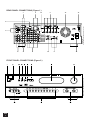
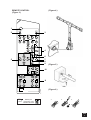
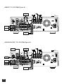
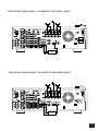
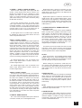
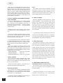
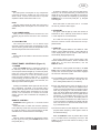
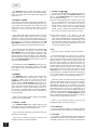
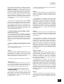
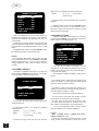
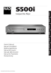
©2000 NAD ELECTRONICS LTD. T 751
NAD
GB
T 751
751
• OWNER'S MANUAL
IMPORTANT SAFETY INSTRUCTIONS
CAUTION ATTENTION:
RISK OF ELECTRIC
SHOCK DO NOT OPEN
RISQUE DE CHOC ELECTRIQUE
NE PAS OUVRIR
CAUTION: TO REDUCE THE RISK OF ELECTRIC SHOCK,
DO NOT REMOVE COVER (OR BACK). NO USER
SERVICEABLE PARTS INSIDE. REFER SERVICING TO
QUALIFIED SERVICE PERSONNEL
Warning: To reduce the risk of fire or electric shock, do not expose this
unit to rain or moisture.
The lightning flash with an arrowhead symbol within an equilateral triangle is intended to alert the user to the presence of uninsulated “dangerous voltage” within the product’s enclosure that may be of sufficient
magnitude to constitute a risk of electric shock to persons.
The exclamation point within an equilateral triangle is intended to alert
the user to the presence of important operating and maintenance
(servicing) instructions in the literature accompanying the product.
ATTENTION
POUR ÉVITER LES CHOC ELECTRIQUES, INTRODUIRE LA LAME
LA PLUS LARGE DE LA FICHE DANS LA BORNE CORRESPONDANTE DE LA PRISE ET POUSSER JUSQU’AU FOND.
CAUTION
TO PREVENT ELECTRIC SHOCK MATCH WIDE BLADE OF PLUG
TO WIDE SLOT FULLY INSERT.
If an indoor antenna is used (either built into the set or installed separately),
never allow any part of the antenna to touch the metal parts of other electrical
appliances such as a lamp, TV set etc.
CAUTION
POWER LINES
Any outdoor antenna must be located away from all power lines.
OUTDOOR ANTENNA GROUNDING
Do not place this unit on an unstable cart, stand or tripod,
bracket or table. The unit may fall, causing serious injury to a
child or adult and serious damage to the unit. Use only with a
cart, stand, tripod, bracket or table recommended by the manufacturer or sold with the unit. Any mounting of the device on a
wall or ceiling should follow the manufacturer’s instructions
and should use a mounting accessory recommended by the
manufacturer.
An appliance and cart combination should be moved with care. Quick stops,
excessive force and uneven surfaces may cause the appliance and cart combination to overturn.
Read and follow all the safety and operating instructions before connecting or
using this unit. Retain this notice and the owner’s manual for future reference.
All warnings on the unit and in it’s operating instructions should be adhered to.
Do not use this unit near water; for example, near a bath tub, washbowl, kitchen
sink, laundry tub, in a wet basement or near a swimming pool.
The unit should be installed so that its location or position does not interfere with
its proper ventilation. For example, it should not be situated on a bed, sofa, rug
or similar surface that may block the ventilation openings; or placed in a built-in
installation, such as a bookcase or cabinet, that may impede the flow of air
through its ventilation openings.
If an outside antenna is connected to your tuner or tuner-preamplifier, be sure
the antenna system is grounded so as to provide some protection against voltage surges and built-up static charges. Section 810 of the National Electrical
Code, ANSI/NFPA No. 70-1984, provides information with respect to proper
grounding of the mast and supporting structure, grounding of the lead-in wire to
an antenna discharge unit, size of grounding conductors, location of antenna discharge unit, connection to grounding electrodes and requirements for the
grounding electrode.
a. Use No. 10 AWG (5.3mm2) copper, No. 8 AWG (8.4mm2) aluminium, No. 17
AWG (1.0mm2) copper-clad steel or bronze wire, or larger, as a ground wire.
b. Secure antenna lead-in and ground wires to house with stand-off insulators
spaced from 4-6 feet (1.22 - 1.83 m) apart.
c. Mount antenna discharge unit as close as possible to where lead-in enters
house.
d. Use jumper wire not smaller than No.6 AWG (13.3mm2) copper, or the equivalent, when a separate antenna-grounding electrode is used. see NEC Section
810-21 (j).
EXAMPLE OF ANTENNA GROUNDING AS PER NATIONAL ELECTRICAL
CODE INSTRUCTIONS CONTAINED IN ARTICLE 810 - RADIO AND TELEVISION EQUIPMENT.
The unit should be situated from heat sources such as radiators, heat registers,
stoves or other devices (including amplifiers) that produce heat.
The unit should be connected to a power supply outlet only of the voltage and
frequency marked on its rear panel.
The power supply cord should be routed so that it is not likely to be walked on or
pinched, especially near the plug, convenience receptacles, or where the cord
exits from the unit.
Unplug the unit from the wall outlet before cleaning. Never use benzine, thinner
or other solvents for cleaning. Use only a soft damp cloth.
The power supply cord of the unit should be unplugged from the wall outlet when
it is to be unused for a long period of time.
Care should be taken so that objects do not fall, and liquids are not spilled into
the enclosure through any openings.
This unit should be serviced by qualified service personnel when:
A. The power cord or the plug has been damaged; or
B. Objects have fallen, or liquid has been spilled into the unit; or
C. The unit has been exposed to rain or liquids of any kind; or
D. The unit does not appear to operate normally or exhibits a marked change in
performance; or
E. The device has been dropped or the enclosure damaged.
DO NOT ATTEMPT SERVICING OF THIS UNIT YOURSELF.
REFER SERVICING TO QUALIFIED SERVICE
PERSONNEL.
Upon completion of any servicing or repairs, request the service shop’s assurance that only Factory Authorized Replacement Parts with the same characteristics as the original parts have been used, and that the routine safety checks
have been performed to guarantee that the equipment is in safe operating condition.
REPLACEMENT WITH UNAUTHORIZED PARTS MAY RESULT IN FIRE,
ELECTRIC SHOCK OR OTHER HAZARDS.
NAD
2
NOTE TO CATV SYSTEM INSTALLER: This reminder is provided to
call the CATV system installer’s attention to Article 820-22 of the
National Electrical Code that provides guidelines for proper grounding
and, in particular, specifies that the ground cable ground shall be connected to the grounding system of the building, as close to the point of
cable entry as practical.
SAFETY WARNING
CLASS 1 LASER PRODUCT
LUOKAN 1 LASERPLAITE
KLASS 1 LASERAPPARAT
THIS DIGITAL APPARATUS DOES NOT EXCEED THE CLASS B
LIMITS FOR RADIO NOISE EMISSIONS FROM DIGITAL APPARATUS AS SET OUT IN THE RADIO INTERFERENCE REGULATIONS
OF THE CANADIAN DEPARTMENT OF COMMUNICATIONS.
LE PRESENT APPAREIL NUMVERIQUE N’EMENT PAS DE
BRUITS RADIOELECTRIQUES DEPASSANT LES LIMITES
APPLICABLES AUX APPAREILS NUMERIQUES DE LA CALSSE B
PRESCRITES DANS LE REGLEMENT SUR LE BROUILLAGE
RADIO ELECTRIQUE EDICTE PAR LE MINISTERE DES COMMUNICATIONS DU CANADA.
WARNING - INVISIBLE LASER RADIATION WHEN OPEN AND
INTERLOCKS DEFEATED. AVOID EXPOSURE TO BEAM.
VORSICHT! - UNSICHTBARE LASERTRAHLUNG TRITT AUS,
WENN DECKEL GEÖFFNET UND WENN SICHERHEITSVERRIEGELUNG
ÜBERBRÜCKT IST. NICHT DEM STRAHL AUSSETZEN.
ADVARSEL - USYNLIG LASERSTRÅLING VED ÅBNING, NÅR
SIKKERHEDSAFBRYDERE ER UDE AF FUNKTION. UNDGÅ
UDSÆTTELSE FOR STRÅLING.
ADVARSEL - USYNLIG LASERSTRALING NÅR DEKSEL ÅPNES OG
SIKKERHEDSLÅS BRYTES. UNNGÅ EKSPONERING FOR STRÅLEN.
VARING - OSYNLING LASERSTRÅLNING NÄR DENNA DEL ÄR
ÖPPNAD OCH SPÄRRAR ÄR URKOPPLADE. STRÅLEN ÄR FARLIG.
VARO! - AVATTAESSA JA SUOJALUKITUS OHITETTAESSA OLET
ALTTINA NÄKTMÄTONTÄ LASERSÄTEILYLLE. ÄLÄ KAISO SÄTEESEEN.
Manufactured under license from Dolby Laboratories. “Dolby”, “Pro Logic” and the Double-D symbol are trademarks of Dolby Laboratories. Confidential unpublished works. ©1992-1997 Dolby Laboratories, Inc. All rights
reserved.
NAD
3
REAR PANEL CONNECTIONS (Figure 1.)
7
8
10
9
14
13
©2000. NAD ELECTRONICS LTD. T 751
2
1
3
4
5
11
6
12
FRONT PANEL CONNECTIONS (Figure 2.)
©2000. NAD ELECTRONICS LTD. T 751
751
NAD
4
REMOTE CONTROL
(Figure 3.)
(Figure 4.)
1
2
3
4
6
7
8
9
5
(Figure 5.)
10
751
NL
Batterij niet
weggooien maar
inleveren als KCA
NAD 2000 T751 RC
11
(Figure 6.)
1
2
3
NAD
5
SIMPLE T 751 SYSTEM (Figure A.)
TV
VIDEO
©2000. NAD ELECTRONICS LTD. T 751
STEREO AUDIO
TAPE
IN / OUT
CD
IN
VCR
IN / OUT
SOPHISTICATED T 751 SYSTEM (Figure B.)
AUDIO / GAMES
IN
TV
©2000. NAD ELECTRONICS LTD. T 751
VIDEO
STEREO AUDIO
SUBWOOFER
TAPE
IN / OUT
CD
IN
VCR
IN / OUT
NAD
6
©2000. NAD ELECTRONICS LTD. T 751
THE OPTICAL DIGITAL INPUT 1 IS LINKED TO THE VIDEO 1 INPUT.
THE COAXIAL DIGITAL INPUT 2 IS LINKED TO THE VIDEO 2 INPUT.
VIDEO
©2000. NAD ELECTRONICS LTD. T 751
STEREO AUDIO
COMPOSITE
VIDEO OUT
DVD
DIGITAL
COAXIAL
OUT
S VIDEO OUT
NAD
7
GB
NAD T 751 SURROUND SOUND RECEIVER
NOTES ON INSTALLATION.
Your NAD T 751 should be placed on a firm, level
surface. Avoid placing the unit in direct sunlight or
near sources of heat and damp.
Allow adequate ventilation. Do not place the unit on
a soft surface like a carpet. Do not place it in an
enclosed position such a bookcase or cabinet that
may impede the air-flow through the ventilation slots.
Make sure the unit is switched off before making
any connections.
The RCA sockets on your NAD T 751 are color
coded for convenience. Red and white are Right and
Left audio respectively, orange for digital input, yellow
for Video Composite and NAD Link.
Use high quality leads and sockets for optimum
performance and reliability. Audio RCA leads will
function correctly for video signals, although it is recommended to use dedicated video leads where possible. For the digital inputs use dedicated leads for
digital signal transfer. Ensure that leads and connectors are not damaged in any way and all connectors
are firmly pushed home.
For best performance, use quality speaker leads of
16 gauge (1.5mm) thickness or more.
If the unit is not going to be used for some time,
disconnect the plug from the AC socket.
Should water get into your NAD T 751, shut off the
power to the unit and remove the plug from the AC
socket. Have the unit inspected by a qualified service
technician before attempting to use it again.
Do not remove the cover, there are no user-serviceable parts inside.
Use a dry soft cloth to clean the unit. If necessary,
lightly dampen the cloth with soapy water. Do not use
solutions containing benzol or other volatile agents.
REAR PANEL CONNECTIONS (Figure 1.)
FM ANTENNA
A ribbon wire FM antenna is included and should
be connected to the FM connector at the rear of the
unit (Fig. 4) using the ‘balun’ adapter supplied. The
ribbon aerial should be mounted on a vertical surface
and placed so that it forms a ‘T’.
Experiment with placement of the antenna to find
the position that gives the best signal strength and
lowest background noise. An inadequate FM signal
normally results in high levels of hiss, especially in
stereo, and interference from external electrical
sources. In areas of poor FM reception, the tuner
section’s performance can be improved by using an
externally mounted FM antenna. A qualified aerial
installer will be able to advise and fit a recommended
aerial for your reception conditions.
2. AM STEPPING FREQUENCY
Worldwide models are equipped with a switch that
controls the AM band tuning steps. Please set this
switch to match the AM band tuning step frequency
as below:
• 120V version : 10kHz
• 230V version : 9kHz
3. TAPE 1 & CD INPUT
TAPE 1
Connections for analogue recording and playback
to an audio tape recorder of any type, such as a cassette, reel-reel, DAT, MD or DCC. Using twin RCA-toRCA leads, connect to the left and right ‘Audio
Output’ of the tape machine to the TAPE 1 IN connectors for playback. Connect the left and right ‘Audio
Input’ of the tape machine to the TAPE 1 OUT connectors for recording.
CD INPUT
Input for CD player (analogue audio signal) or other
line-level signal source. Use a twin RCA-to-RCA lead
to connect the CD player’s left and right ‘Audio
Outputs’ to this input.
1. FM & AM ANTENNA
AM ANTENNA
An AM loop antenna is supplied with the T 751 and
is required for AM reception. Open the clip terminal
lever and insert the wire from the antenna. Closing
the lever will lock the wire in place (Fig. 5). Test various positions for the antenna, but always ensure the
loop is placed vertically for best reception. Placing the
antenna close to large metal items such as metal
shelves or radiators may interfere with reception.
NOTE:
When reception is not satisfactory using the supplied AM loop antenna alone, connection of an external antenna is recommended. Do not connect anything other than a loop antenna to the AM ANTENNA
terminal. Do not remove the AM loop antenna. The
antenna cable to the loop antenna must not exceed 3
meters.
NAD
8
4. 5.1 CHANNEL INPUTS
Inputs for the multi-channel audio signals from an
external decoder, such as an MPEG decoder or a
DVD player with integrated decoder. Use two twin
RCA-to-RCA lead to connect the decoder’s front left
and right ‘Audio Outputs’ to the Front left and right
inputs, and the decoder’s Surround left and right outputs to the Surround left and right inputs. Use a third
twin RCA-to-RCA lead to connect the decoder’s subwoofer output to the Subwoofer input and the
decoder’s Center channel output to the Center channel input. Make sure you to follow color coding of the
plugs to ensure that both Center and Subwoofer are
connected correctly, for instance, use the red plugs at
either end to connect the center channel and the
white plugs for the subwoofer channel.
GB
5. VIDEO 1 - VIDEO 4 (AUDIO & VIDEO)
Apart from the audio signal, these inputs will also
accept a video signal which will be routed to the
Monitor Out sockets (No. 8) for a television or video
projector. The Video 1, 2 and 3 inputs also have the
option of a Video Composite connection (using the
yellow RCA socket) or an S-Video connection (using
the Mini-Din connector).
The S-Video standard allows for higher quality
video signal transfer when compared to the Video
Composite standard. If your video components have
an S-Video connector use dedicated S-Video leads to
connect them to the T 751 in the same way as
described with the Video composite equivalents.
A video signal fed to an S-Video input socket will
be available on both the S-Video Monitor Out and
Video composite Monitor Out.
VIDEO 1 & VIDEO 2 (AUDIO)
Inputs for the audio playback and video signal from
a video device such as a stereo TV, DVD player,
satellite cable TV receiver or a Laser Disc. Using twin
RCA-to-RCA leads, connect to the left and right
‘Audio Out’ of the video device to these inputs. Using
a single RCA-to-RCA lead (Video Composite) or SVideo lead, also connect the video output of the video
device; refer also to the description of S-Video and
Video Composite in section No. 5 of this chapter.
VIDEO 1 & VIDEO 2 can be used for video playback
only. Use VIDEO 3 or VIDEO 4 if you want to connect
a VCR for recording and playback through the T 751.
The optical Digital Input 1 (No. 6) is linked to the
Video 1 input. Select Video 1 to hear a source connected to Digital Input 1.
The coaxial Digital Input 2 (No. 6) is linked to the
Video 2 input. Select Video 2 to hear a source connected to Digital Input 2.
VIDEO 3 & VIDEO 4 (AUDIO)
Connections for the audio recording and playback
to a VCR or other video recorder. Using twin RCA-toRCA leads, connect to the left and right ‘Audio Out’ of
the VCR to the VIDEO 3 or VIDEO 4 IN connectors
for playback. Connect the left and right ‘Audio In’ of
the VCR to the VIDEO 3 or VIDEO 4 OUT connectors
for recording. Using a single RCA-to-RCA (Video
Composite) lead or S-Video lead, also connect the
video output of the VCR to Video In (only Video
Composite for Video 4) for Video playback. Connect
the Video Input of the VCR to Video Out of the NAD T
751 receiver for recording of video signals. Refer also
to the description of S-Video and Video Composite
above in this section.
6. DIGITAL AUDIO INPUTS
The T 751 has three digital audio inputs to allow for
connection of DVD, CD or other digital sources:
Digital Audio Input 1 allows for connection of a digital source with an Optical output. Use a cable terminated with a TOS Link connector. This digital input is
linked to the Video 1 input.
Digital Audio Inputs 2 & 3 allow for connection of a
digital source with a Coaxial digital output. Use a
cable with the right impedance, specifically designed
for the transfer of digital signals. These digital inputs
are linked respectively to VIDEO INPUT 2 and
VIDEO INPUT 3.
7. AUDIO PRE-OUTS / SUBWOOFER OUT
AUDIO PRE-OUTS
The NAD T 751 receiver has five power amplifiers
built-in to power all the speakers connected to it (Left,
Right, Center, Left Surround, Right Surround). It is
also possible to use the T 751 as a pre-amplifier to
drive external power amplifiers. This way, you use all
the control functions the T 751 provides, such as
input select, surround mode, volume, tone controls,
etc., but the external power amplifier actually powers
the speaker connected to it instead of the T 751’s
integrated power amplifier for that channel.
Connect the RCA-to-RCA leads from the Front left
and Right, Center, and/or Surround Left and Right
Audio pre-out connectors to the external amplifiers.
Connect speakers to the external amplifiers.
NOTES:
Never connect the T 751’s speaker outputs and the
speaker outputs of an external amplifier to the same
speakers. When headphones are inserted the signals
from all audio pre-out outputs will be muted.
Before making any connections, check that the T
751 and the power amplifiers it will be connected to
are switched off. With volume turned down to a low
level, switch power on only after all connections have
been made.
SUBWOOFER OUT
Unlike for the full range five channels as described
above, there is no power amplifier built-in for an additional subwoofer. The Subwoofer pre-out allows for
connection to a sub-bass speaker system with its
own external or integrated power amplifier (“active”
subwoofers).
NOTE:
When headphones are inserted the signal from the
Subwoofer output will be muted.
8. MONITOR OUT
Composite Video and S-Video outputs for connecting a TV or Video Monitor to view video sources connected to VIDEO 1 to VIDEO 5. Using a Video RCAto-RCA lead, connect the ‘Video Line In’ on the TV or
monitor to the MONITOR OUT.
NAD
9
GB
Note that an S-Video signal from Video input 1
through 3 will also be available as a Video Composite
signal on Monitor out, if the corresponding source is
selected. The composite video input signals from
Video 1 to 5 (No. 5; yellow sockets) will also be available as S-Video signal on the Monitor Out socket. If
you use both S-Video and Video composite sources,
you will only need to connect the S-Video Monitor Out
to the television or projector.
9. FRONT, CENTER & SURROUND SPEAKERS
FRONT SPEAKERS
Connect the right speaker to the terminals market
‘R +’ and ‘R -’ ensuring that the ‘R +’ is connected to
the ‘+’ terminal on your loudspeaker and the ‘R -’ is
connected to the loudspeaker’s ‘-’ terminal. Connect
the terminals marked ‘L +’ and ‘L -’ to the left speaker
in the same way.
NOTE:
The Center and/or Surround speakers must be
selected as Large or Small in the Set-up menu
“SPEAKER SELECTION” when speakers are connected to these outputs. Refer also to chapter “On
Screen Display (OSD)” for more information.
10. SOFT CLIPPING
When any amplifier is driven beyond it’s power
output capabilities, a hard, distorted sound can be
heard on very loud sounds. This is caused by the
amplifier cutting off or ‘hard clipping’ the peaks of
sound that it was not designed to reproduce. The
NAD Soft Clipping circuit gently limits the output of
the system to minimize audible distortion if the ampli-
Always use heavy duty (16 gauge; 1.5mm or thicker) stranded wire to connect loudspeakers to your T
751.
Unscrew the speaker terminal’s plastic bushing.
Insert the pin or bare cable end into the hole of the
terminal and then secure the cable by tightening
down the terminal’s bushing (Fig. 6).
To avoid any danger of bare metal from the speaker cables touching the back panel or another connector, ensure that there is only 1/2” (1.27cm) of bare
cable or pin and no loose strands of speaker wire.
NOTE:
This unit is designed to produce optimum sound
quality when speakers with impedance within the
set’s ranges are connected. Please check the following information and choose speakers with the correct
impedance for the connections.
fier is overdriven.
If your listening involves moderate power levels you
may leave the Soft Clipping switch off. If you are likely to play at high levels that exceed the amplifier’s
power capability, then switch Soft Clipping on.
11. NAD-LINK IN OUT
The NAD-Link connector is used to pass commands from other units fitted with NAD-Link connectors. This allows centralized control of a complete
system, and also allows some of the basic functions
of other NAD components (such as a CD player or
cassette deck) also equipped with NAD-Link to be
FRONT SPEAKERS:
4 ohms min. per speaker
controlled with the receiver’s remote control. To func-
CENTER SPEAKER:
4 ohms min.
tion with such other units, connect the T 751’s NAD-
SURROUND SPEAKERS: 4 ohms min. per speaker
Link Out to the NAD-Link In on the other unit. NADLink connectors can be daisy-chained, IN to OUT, so
CENTER SPEAKER
This connects the center loudspeaker that is used
when the T 751 is operated in Dolby* Digital, DTS,
Dolby Pro Logic, EARS surround sound mode or with
the 5.1 Ch. input selected.
Connect the center speaker in the same way as
described with FRONT SPEAKERS above.
that a whole system can be controlled from the
remote control facilities of one unit.
12. SWITCHED POWER OUTLETS
(120V North American versions only)
The AC power cords of other stereo components,
such as a CD player, may be plugged into these
SURROUND SPEAKER
This connects the Surround loudspeakers that are
used when the T 751 is operated in Dolby Digital,
DTS, Dolby Pro Logic, EARS Surround sound modes
or with the 5.1 Ch. input selected.
Connect the surround speakers in the same way as
described with FRONT SPEAKERS above.
NAD
10
accessory outlets.
Components plugged into the outlets will be
switched on and off as the T 751 is switched from
stand-by or off to on and vice versa.
GB
NOTE:
The total power consumption of any components
connected to the AC outlets may not exceed 120
Watts. Never connect the mains lead of a power
amplifier to either outlets of the NAD T 751.
NOTE:
The AC outlets should be used with units with a
COMBINED power consumption of no more than 120
Watts.
In Stand-by mode the T 751 uses very little power.
However, it is recommended that you switch the unit
totally off if it is not going to be used for more than a
couple of days. Switch off completely by pressing the
POWER button on the front panel (No. 1), all lights
will extinguish.
Press this button to switch the unit on. To switch
the unit off, press this button again.
2. STAND-BY
13. AC POWER CORD
After you have completed all connections to the
amplifier, plug the AC line cord into a “live” wall socket.
14. COOLING FAN
The cooling fan allows T 751 to deliver high
amounts of power without the unit becoming too hot.
The fan will only operate when the temperature of the
internal components starts to become hot.
NOTE:
Ensure that the air outlets of the fan aren’t blocked
in any way.
FRONT PANEL CONTROLS (Figure 2.)
This green LED will light up when the receiver is
switched On, but in Stand-by mode. Refer to section
1 in this chapter for more information.
The LED will also light up when the receiver
receives a remote control command from the supplied handset.
3. DISPLAY
The T 751 supports RDS PS and RDS RT. With
stations carrying RDS information, “RDS” will light up
in the display panel, and the station’s RDS name is
automatically displayed (RDS PS).
Some radio stations, which support RDS, also
transmit additional information, known as Radio Text
(RDS RT). To view this information, use the
DISPLAY button.
1. POWER
Press the POWER button to switch the receiver to
its ‘Stand-by’ mode. The Stand-by indicator (No. 2)
over the power button will light up. On the front panel,
press any of the input selector buttons (No. 11) to
switch the receiver on. From the remote control,
press the green Stand-by button (No. 1 on remote
control drawing) to switch the unit on. The display will
light up indicating which input was selected; the
Stand-by indicator will extinguish.
With stations carrying RDS information, the DISPLAY button scrolls between three different display
modes, each successive push of the button engages
the next one of the three modes:
Pressing the POWER switch again will turn the unit
OFF completely. The NAD T 751 receiver uses a
memory back-up system to store surround sound trim
settings and Preset station information for the tuner
section. This information is retained for several
weeks, even the unit is switched off completely or
unplugged.
STAND-BY button (green, No. 1 on remote control
drawing):
b) From the default mode, press the button once to
view Radio Text (RT). This can be additional information such as the presenter’s or program’s name;
what song is playing, etc. This text scrolls continuously over the 8 alphanumeric display segments. It
takes a few seconds for the tuner to gather the RT
information, so immediately after tuning to a station and selecting to view RT the display will indicate “NO TEXT” and default to the station name. If
no RT information is available, the display will also
show “NO TEXT” for three seconds before reverting to the default mode.
Press this button to switch the unit from operating
to the Stand-by mode and vice versa. Press this button again to switch to unit on from Stand-by; the last
selected source will be indicated in the display.
c) Press the button from the display RT mode to display the station frequency. Press again to return to
the default mode (a).
NOTE:
Stand-by mode is indicated by the Stand-by indicator (No. 2) just over the green POWER button on the
front panel (No. 1).
When the DISPLAY button is pressed when tuned
to a non-RDS station the display will show “NO
NAME” for three seconds before reverting to the
default display:
REMOTE CONTROL:
a) In the default mode, the station’s RDS name is displayed, Program Service (PS; normally the station’s calling letters, BBC R3, for instance).
NAD
11
GB
The DISPLAY button toggles the display to show
either the station frequency or user entered station
name. If no user name was entered the display will
just flash once.
7. DOWN / UP 1 and 2
4. FM MUTE / MONO
This button combines two functions; it switches the
tuner from Stereo to Mono and disengages the muting circuitry at the same time. The muting circuit will
mute the tuner in between radio stations when
searching or tuning. This way the tuning noise is
avoided.
a) Preset mode (indicated in the display area): Press
the “ 1 ” (down) button to scroll to a lower number
Preset; press the “ 2 ” (up) button to scroll to a
higher Preset number. This is a “wrap-around”
function, so that going from the highest number
Preset, the tuner will go to the lowest Preset number or vice-versa when tuning either up or down.
Very weak radio station signals however may be
suppressed by the muting circuit. if such a very weak
station is in stereo it will have a high level of background hiss. Switching to Mono Mode and disengaging the muting circuit by depressing the FM
MUTE/MONO button will allow the station to be heard
and will cancel most or all of this background noise.
b) Tune mode: Press the “ 1 ” (down) or “ 2 ” (up)
button for more than 1/2 second to engage automatic tuning respectively up or down the frequency
band. The tuner will search automatically for the
first reasonably strong radio station, where it will
stop. Press the Down/Up button again for 1/2 second to start searching again.
In normal operation the mute circuit is engaged, the
display indicates “FM MUTE”. Press the FM
MUTE/MONO button to disengage the muting circuit
and switch from stereo to mono reception. “FM
MUTE” will extinguish in the display. Also, “STEREO”
will extinguish if a stereo broadcast was received.
Press the FM MUTE/MONO switch again to return to
Auto Stereo FM operation.
NOTE:
Automatic tuning is available on both FM and AM.
In combination with the MEMORY button (No. 5) a
preset number can be emptied. (Refer to the separate chapter “Storing and Recalling Presets” for more
information.)
5. MEMORY
The MEMORY button is used to store stations into
the Preset Memory (1-30 Presets on FM, 1-10
Presets on AM), used in conjunction with the
DOWN/UP (No. 7) buttons on the front panel. In combination with the FM MUTE/MONO button (No. 4) a
preset number can be emptied. When Memory is
active, the Preset number flashes and the red “MEMORY” indicator is shown in the Display Panel. If no
other button is pressed within 10 seconds “MEMORY” will stop flashing and the receiver will default to
its previous state.
Refer to the separate chapter “Storing and recalling
Presets” for more information.
6. PRESET / TUNE
The PRESET/TUNE button toggles between the
Preset and Tune mode. When Preset mode is selected, “PRESET” lights up in the display area.
NAD
12
The function of these buttons depends on the tuning mode selected with the PRESET/TUNE button
(No. 6). The PRESET/TUNE button toggles between
the two operation modes:
By briefly tapping the “ 1 ” (down) or “ 2 ” (up) buttons you can engage manual tuning respectively
down or up the frequency band for precise tuning to a
specific frequency. With each successive tap of the
keys, the tuner will take 0.1 MHz steps (120V version) or 0.05 MHz steps (230V version) on FM so you
can accurately tune into the desired frequency. For
AM the tuning steps are factory set at 9 kHz for the
230V version or 10 kHz for the 120V version). Set the
AM STEP switch on the back panel (No. 2 in back
panel drawing) to manually set the AM tuning steps to
9 or 10 kHz (refer also to chapter “Rear Panel
Connections” section 2: “AM stepping frequency”).
This tuning mode can also be useful when trying to
receive a radio station which is too weak for the auto
search mode. When tuned accurately to a station,
“2TUNED 1” will light up in the display. Very weak
radio station signals however may be suppressed by
the muting circuit. If such a very weak station is in
stereo it will have a high level of background hiss.
Switching to Mono Mode and disengaging the muting
circuit by depressing the FM MUTE/MONO button
(No. 4) will allow the station to be heard and will cancel most or all of this background noise.
Refer to the separate chapter “Storing and
Recalling Presets” for more information.
8. VFL DISPLAY
Vacuum Fluorescent Display. The display area will
show all vital information when the unit is operational.
Up to 40 Presets, either AM (10 Presets) or FM (30
Presets), can be stored.
9. VOLUME
Refer also to separate chapter “Storing and
Recalling Presets” for more information.
The Volume control adjusts the overall loudness of
the signals being fed to the loudspeakers. Unlike conventional controls, the T 751’s volume control doesn’t
GB
have a start of end position. Volume can also be
adjusted from the remote control handset using the
MASTER VOLUME Up or Down buttons (No. 4 in
remote control drawing). The Volume control does
not affect recordings made using the Tape, Video 3
and Video 4 outputs but will affect the signal going to
the Pre-amp output (Audio Pre Out). The volume
level is indicated in the display panel when it is being
adjusted. After three seconds the display defaults to
its previous status. Volume setting can range from ∞ to +18dB ······
On the remote control handset, press the MUTE
button (No. 3) to temporarily switch off the sound to
the speakers and headphones. Mute mode is indicated by “MUTING” flashing in red in the display area.
Press MUTE again to restore sound. Mute does not
affect recordings made using the Tape, Video 3 and
Video 4 outputs but will affect the signal going to the
Pre-amp output (Audio Pre Out).
10. HEADPHONE SOCKET & VIDEO 5 INPUT
HEADPHONE SOCKET
A 1/4” stereo jack socket is supplied for headphone
listening and will work with conventional headphones
of any impedance. The volume and tone controls are
operative for headphone listening. Use a suitable
adapter to connect headphones with other types of
connectors such as 3.5mm stereo ‘personal stereo’
jack plugs.
Inserting a headphone will automatically turn off all
speakers and signals from the Audio Pre-Out sockets.
The sound from the EXT. 5.1 CH input is not available on the headphones socket.
NOTES:
In the OSD menu “Speaker settings” be sure to
have selected and adjusted a preset with “MAIN
SPEAKERS” set to “LARGE”. If set to “SMALL”, bass
reponse will be limited. Refer also to Chapter “On
Screen Display (OSD)” for more information.
Listening at high levels can damage your hearing.
VIDEO 5 INPUT
For easy and temporary connection you can connect a camcorder (playback only) or video game console. If the game console or camcorder is mono, connect the audio lead to the R (Right) audio socket.
11. AUDIO & VIDEO INPUT SELECTORS &
SURROUND MODE
These buttons select the active video and audio
input to the T 751 and the audio signal sent to the
loudspeakers, Tape, Video 3 & 4 and TV monitor outputs. Video inputs 1, 2 and 3 also select respectively
the Digital Inputs 1, 2 and 3.
The name of the Input and Surround Mode will be
shown in the Display Panel.
VIDEO 1
Video 1 selects the signal from a TV/Satellite/Cable
receiver or DVD player connected to VIDEO 1 as the
active input. “VIDEO-1” is shown in the Display Panel
when selected.
The Digital Input 1 is linked to the Video 1 input
(marked Digital In on back panel; No. 6). Digital Input
1 allows for connection of a digital source with an
Optical digital output. Whenever Video 1 is selected,
Digital Input 1 will also be selected; in the display the
“DIGITAL 1” indicator will start to blink. If a digital
audio signal is detected, the “DIGITAL 1” indicator will
stop blinking and remain lit. If no digital audio signal
is detected, “DIGITAL 1” indicator will cease blinking
and extinguish.
VIDEO 2
Video 2 selects the signal from a TV/Satellite/Cable
receiver or DVD player connected to VIDEO 2 as the
active input. “VIDEO-2” is shown in the Display Panel
when selected.
The Digital Input 2 is linked to the Video 2 Input
(marked Digital In on back panel; No. 6). Digital Input
2 allows for connection of a digital source with a
Coaxial digital output. Whenever Video 2 is selected,
Digital Input 2 will also be selected; in the display the
“DIGITAL 2” indicator will start to blink. If a digital
audio signal is detected, the “DIGITAL 2” indicator will
stop blinking and remain lit. If no digital audio signal
is detected, “DIGITAL 2” indicator will cease blinking
and extinguish.
VIDEO 3 & VIDEO 4
Video 3 & 4 select the signal from a
TV/Satellite/Cable receiver, DVD player or VCR connected to VIDEO 3 or VIDEO 4 as the active input.
“VIDEO-3” or “VIDEO-4” is shown in the Display
Panel when selected. The Video 3 & 4 inputs also
have video and analogue audio outputs specifically
for recording video devices.
The Digital Input 3 is linked to the Video 3 input
(marked Digital In on back panel; No. 6). Digital Input
3 allows for connection of a digital source with a
Coaxial digital output. Whenever Video 3 is selected,
Digital Input 3 will also be selected; in the display the
“DIGITAL 3” indicator will start to blink. If a digital
audio signal is detected, the “DIGITAL 3” indicator will
stop blinking and remain lit. If no digital audio signal
is detected, “DIGITAL 3” indicator will cease blinking
and extinguish.
VIDEO 5
Selects the camcorder or video game console connected to the Video 5 front panel inputs as the active
input. “VIDEO-5” is shown in the Display Panel when
selected.
NAD
13
GB
EXT. 5.1
Selects the multi-channel output signal from the
DVD player or external decoder source (such as
MPEG, for instance) connected to the 5.1 Ch. input
as the active input.
NOTE:
No Ext. 5.1 audio signal is available from headphones socket, the Tape, Video 3 and Video 4 outputs when the Ext. 5.1. input has been selected.
SURROUND MODE
With the Surround Mode buttons the available surround sound modes can be selected. The selected
Surround mode is permanently indicated in the display area and is also shown for 3 seconds in the
large Star-Burst section of the display. The Surround
Mode buttons scroll through the available surround
sound modes:
With any of the Digital Inputs 1, 2 & 3 (press Video
1, 2 or 3 respectively to select), the T 751 automatically recognizes if the selected source carries a Dolby
Digital ™ or DTS ™ signal. When no Dolby Digital or
DTS signal is available, the Surround Mode buttons
scrolls through the other available surround sound
modes:
Stereo
Pro Logic
Ears
Stereo, etc.
Surround Mode if the source is either Dolby Digital or
DTS and a Digital Audio input is used.
An external source such as a decoder or DVD player with a decoder built-in (MPEG for instance) can be
connected to the 5.1Ch input (No. 4 on the front
panel). When the EXT 5.1 CH. input is selected, no
other surround modes are available.
To obtain the best performance possible it is important that the system and all speakers have been set
up correctly. Refer to the chapters “On Screen
Display” and “Setting Up the Surround System”.
TAPE MONITOR
Selects the output from a tape recorder when playing back tapes or monitoring recordings being made
through the Tape sockets. Press the TAPE MONITOR button once to select it and again to return to
the normal input selection.
The Tape Monitor function does not override the
current input selection. For example, if the CD is the
active input when Tape Monitor is selected, the CD
signal will continue to be selected and is sent to the
Tape Out, Video 3 and Video 4 Out sockets, but it is
the sound from recorder connected to Tape that will
be heard on the loudspeakers. When Tape Monitor is
selected, “TAPE MONITOR” will remain lit until Tape
Monitor is disengaged again.
With either Dolby Digital or DTS surround mode
engaged, the Dolby Pro Logic and Ears surround
modes cannot be selected.
CD
Selects the CD as the active input.
Dolby Digital and DTS has six independent channels available in total: Left, Center, Right, Surround
left, Surround Right and an “Effects Channel”
(Subwoofer).
FM
Selects FM radio. FM is also automatically selected
when an FM Preset is selected.
The Dolby Digital signal allows for several channel
configurations.
AM
Selects AM radio. AM is also automatically selected
when an AM Preset is selected.
DTS digital surround is an Encode/Decode system
that currently delivers six discrete channels (5.1) of
“Master-Quality” up to 24-bit audio.
Dolby Pro Logic decodes the center and surround
sound signals embedded in stereo movie sound
tracks from e.g. video, Laser Disc or TV. To decode
correctly, the source must be a Dolby Surround or
Dolby Stereo soundtrack.
In the EARS (Enhanced Ambiance Retrieval
System) Surround Mode, a realistic level of ambience
of surround sound is added to a normal stereo source
such as a CD or FM radio.
VIDEO OUTPUT
The video signal available on the S-Video and
Video Composite outputs is dependent on the selected video input (VIDEO-1, VIDEO-2, VIDEO-3,
VIDEO-4, VIDEO-5). However, when one of the
audio-only sources is selected (FM, AM, CD, Tape
Monitor or Ext. 5.1) the last selected video signal
from one of the video inputs will be present on these
outputs. This way you can watch a DVD player or
video whilst listening to the CD player.
The display indicates which video signal is routed
to the MONITOR OUT sockets (No. 8 on back panel).
12. BASS & TREBLE CONTROLS
NOTES:
Dolby Digital or DTS are only available as a
NAD
14
The T 751 is fitted with BASS and TREBLE tone
controls to adjust the overall tonality of your system.
GB
The 12 o’clock position is ‘flat’ with no boost or cut
and a detent indicates this position.
Rotate the control clockwise to increase the
amount of Bass or Treble. Rotate the control anticlockwise to decrease the amount of Bass or Treble.
These controls affect the Left and Right Front speakers. The Tone controls do not affect recordings made
using the Tape or Video line outputs but will affect the
signal going to the Pre-amp outputs (Audio Pre Out).
STORING AND RECALLING PRESETS
Deleting a stored Preset:
You can empty a Preset by deleting the stored
information:
• Select the Preset to be emptied.
• Press the MEMORY button (No. 5), followed by
the FM MUTE/MONO button (No. 4). The Preset will
then be deleted and ‘--’ appears as the Preset number.
You can also store a new station into a used
Preset, by simply going through the Preset storing
process and placing a new station over the existing
one.
To store a Preset:
• Tune to the radio station you wish to enter into a
Preset (refer to chapter “Front Panel Controls”; sections 6 and 7). If the station is transmitting RDS information, the RDS indicator will light up and station initials will be shown in the Display Panel. If a non-RDS
station is found, then just the frequency will be
shown.
• To store that station as a Preset, press MEMORY
(No. 5). “MEMORY” and the preset section in the display panel will start to flash. If no other button is
pressed within 10 seconds, “MEMORY” will stop to
flash and the receiver will default to its previous state.
• Press either the “ 1 ” (down) or “ 2 ” (up) button to
select which Preset number you wish to assign to the
station (from 1 to 30 on FM and 1 to 10 on AM),
shown as a flashing number in the Display Panel, and
then press MEMORY (No. 5) again. The Memory light
in the Display Panel will go out and the station is now
stored in your NAD T 751’s memory.
To exit the Memory mode without storing a station,
leave all the tuner controls untouched; the Memory
mode will automatically cancel itself after 10 seconds.
The Memory Presets have a memory back-up, so
they will remain stored for several weeks even if the
Receiver is switched off or unplugged from the mains
supply.
NOTE:
You can enter a new station into an unused Preset
or over-write an existing programmed Memory
Preset. By doing this you will replace the radio station
previously held on that Preset number.
Recalling a Preset station:
• To select a Preset station, select the Preset mode
by pressing the PRESET/TUNE button (No. 6) until
“PRESET” lights up in the display.
• Press either the “ 1 ” (down) or “ 2 ” (up) button
(No. 7) until the right Preset is found and shown in
the Display Panel.
NOTE:
Any unused Presets will be skipped.
REMOTE CONTROL (Figure 3.)
Apart from all the key functions, the T 751’s
Remote Control handset also gives access to functions not available on the front panel. It also has additional controls to remotely operate NAD Cassette and
CD machines. It will operate up to a distance of 16ft
(5m).
Alkaline batteries are recommended for maximum
operating life. Two AAA (R 03) batteries should be fitted in the battery compartment at the rear of the
Remote Control handset. When replacing batteries,
check that they have been put in the right way round,
as indicated on the base of the battery compartment.
The EXT 5.1, VIDEO 1 TO 5, TAPE MON., AM, FM
and CD Input selector buttons, and PRESET/TUNE,
DOWN/UP and DISPLAY buttons perform the same
function as those on the front panel of the T 751.
There are a few differences and extra functions with
the remote control handset however (numbers refer
to Fig. 3):
1. STAND-BY
Press this green button to switch the unit from
operating to the Stand-by mode and vice versa:
Press this button again to switch the unit on from
Stand-by; the last selected source will be indicated in
the display.
2. SLEEP
Press SLEEP to make the T 751 automatically
switch off after a preset number of minutes. Pressing
the SLEEP button once will set the sleep time to 90
minutes, after which the T 751 will automatically
switch off into Standby mode. Sleep mode is shown
on the Display Panel. To adjust the Sleep Delay,
press the SLEEP button, each consecutive press will
reduce the sleep time in 30-minute increments, as
shown in the Display Panel. To cancel the Sleep
mode, continue pressing the SLEEP button until the
sleep time returns to 0 minutes. Pressing the
POWER on the front panel (No.1) or STAND-BY button will also cancel the Sleep mode.
3. MUTE:
Press the MUTE button to temporarily switch off the
NAD
15
GB
sound to the speakers and headphones. Mute mode
is indicated by “MUTING” flashing in red in the display area. Press MUTE again to restore sound. Mute
does not affect recordings made using the Tape outputs but will affect the signal going to the Audio Preouts.
NOTE:
When the unit is in mute mode, any adjustment of
the VOLUME CONTROL on the front panel (No.9)
will release the muting, i.e. the original volume level
will be resumed.
7. CHANNEL SELECT
Although the T 751 is correctly set-up it may sometimes be desirable to make minor adjustments to suit
particular software. Pressing the CHANNEL button
allows for direct adjustment of Center, Rear and
Subwoofer levels. Press the CHANNEL button to
scroll to the next speaker. Both display panel and
OSD show which speaker can be adjusted. Use the
cursor 1 and 2 button to respectively decrease or
increase the level for the current speaker.
Pressing the CHANNEL button also gives access
to CHANNEL BALANCE in the OSD directly:
CENTER
4. MASTER VOLUME
Master Volume 3 or 4 respectively increases or
decreases the volume setting for all speakers. The
display panel will indicate the level set. The Volume
control does not affect recordings made using the
Tape and Video, or Tape, Video 3 and Video 4 outputs but will affect the signal going to the Pre-amp
output (Audio Pre Out).
5. CURSOR 3 , 4, 1 AND 2 AND ENTER
The four Cursor buttons are used to navigate the
cursor when using the menus with the On Screen
Display and the ENTER is used to confirm the choice.
Press 3 to move cursor up, 4 to move cursor down,
1 to move cursor left, 2 to move cursor right. Then
press ENTER to access.
REAR R & L
SUB
OFF
Refer also to the chapter “Setting Up the Surround
Sound System” for more information.
8. DYNAMIC RANGE
The DYN. R button, which can be used only in
combination with a Dolby Digital source, incrementally reduces the audio track’s dynamic range in four
steps (100%, 75%, 50% and 25%) to allow for comfortable listening under a variety of conditions. The
normal or default position is 100%.
To adjust the dynamic range, each consecutive
press of the DYN. R button will reduce the value in
25% increments, as shown in the alpha-numeric display section.
Refer also to chapter “On Screen Display” and
“Setting Up the Surround Sound System” for more
information.
NOTE:
Although we usually prefer to reproduce a source’s
full dynamic range (the difference between very loud
and very soft sounds), it may occasionally be desirable to reduce the dynamic range. For example,
when playing a movie late at night, loud explosions
might wake sleeping family members. Simply turning
the volume control down would probably make a
whisper in the next scene inaudible. The DYN. R button solves this dilemma by progressively lowering the
volume of loud peaks while increasing the level of
softer sounds.
6. TEST
9. MODE
With the four cursor buttons the relative volume
level trims for center, left and right surround channels
can be adjusted. Press the CHANNEL button (No. 7)
to select the channel for which you wish to adjust the
level.
Pressing the TEST button, engages the Test signal
generator to allow for adjustment of all speaker levels, so that each channel can be adjusted for equal
loudness at your listening position. The test signal
scrolls automatically with 5-second intervals from
Front Left, Center, Front Right, Rear Right, Rear Left,
to subwoofer in continuous cycles. If an adjustment in
setting is made for one of the speakers, scrolling will
stop until 5 seconds after the adjustment was made.
Both display panel and OSD show which speaker is
being fed with the test signal. Use the cursor 1 and 2
button to respectively decrease or increase the level
for the current speaker. Press the TEST button again
to leave or cancel the Test mode, any changes will be
memorized automatically.
Refer also to chapter “On Screen Display” and
“Setting Up the Surround Sound System” for more
information.
The MODE button scrolls through the available surround sound modes. The button functions in the
same way as the SURROUND MODE button on the
T 751 front panel (No. 11 on front panel drawing).
The selected Surround mode is permanently indicated in the display area and is also shown for 3 seconds in the alpha-numeric display section.
10. CD PLAYER CONTROL
(for use with NAD CD Players).
; engages Pause
9 engages Stop
2 / ; engages Play or toggles between Play and
Pause
∞ or § engages Track skip; press once to go to
the next track or to return to start of current or previous track.
DISC Go to next disc (for NAD CD changers).
NAD
16
GB
11. CASSETTE DECK CONTROL
(For use with single (DECK B) or double transport
(A and B) NAD Cassette Decks).
1 or 2 engages Forward Play or Reverse Play.
0/ ; Record / Pause. Press to put cassette deck
into record-pause. Press Play to start recording.
9 Stops Play or Recording.
5 engages Rewind.
6 engages Fast Forward.
NOTES:
Direct sunlight or very bright ambient lighting may
affect the operating range and angle for the remote
control handset.
The infrared remote control command receiver,
located on the far left of the display window, receives
commands from the remote control. There must be a
clear line-of-sight path from the remote control to this
window; if that path is obstructed, the remote control
may not work.
ON SCREEN DISPLAY (OSD)
The NAD T 751 is equipped with an elaborate On
Screen Display facility (OSD). As the OSD is an
essential tool to set up the various parameters for
Surround sound correctly it is recommended that you
connect your monitor or television to the T 751.
Depending on your source and/or the television
system used you must first select the correct video
system. If the OSD rolls over the screen you must
select another system: PAL or NTSC.
• While pressing the MEMORY button (No. 5) on
the front panel, press the VIDEO 1 input selector button (in section No. 11) repeatedly until the desired
system is shown in the display area.
The OSD can be engaged by pressing one of the
four cursor buttons on the remote control. The
SETUP Menu will appear as below (Fig. 7):
SETUP
1
2
3
4
5
INPUT SETTINGS
CHANNEL BALANCE
CHANNEL DELAYS
SPEAKERS SETTINGS
EXIT
Use the cursor buttons on the remote control to
navigate, select the desired menu and options, then
press ENTER (No. 5) to access. The 3 and 4 button
are used to navigate and select an option (indicated
by highlighting the available option), the 1 or 2 button
to change a setting from the highlighted section and
ENTER to choose the desired option. Otherwise,
highlight EXIT and press ENTER to leave.
The OSD menu are at maximum two “layers” deep;
this means that from the main menu (layer 1) you can
select a sub menu (layer 2).
The other sub menus available are:
1 INPUT SETTINGS
• Highlight INPUT SETTINGS in the SETUP menu
and press ENTER on the remote. You will see a
screen similar to the following (Fig. 8):
INPUT SETTINGS
AUDIO = TUNER
VIDEO = VIDEO 1
MODE = DOLBY DIGITAL
DYNAMIC RANGE = 100%
DO NOT SAVE & EXIT
SAVE & EXIT
• The available choices in each of the fields can be
selected with the 1 or 2 button on the remote; confirm the choice with ENTER button.
AUDIO = identifies the selected audio input
(TUNER, CD, TAPE MONITOR and EXT. 5.1).
VIDEO = identifies the selected video input (VIDEO
1, VIDEO 2, VIDEO 3, VIDEO 4 and VIDEO 5).
MODE = indicates the operating mode of the
selected input (DOLBY DIGITAL, DTS, PRO LOGIC,
EARS, STEREO).
DYNAMIC RANGE = indicates the dynamic range
currently selected (100%, 75%, 50% and 25%) in
Dolby Digital mode only, or N/A for the other modes.
• Highlight SAVE & EXIT and press ENTER to
save the altered settings and return to the SETUP
menu. Otherwise, select DO NOT SAVE & EXIT to
leave without saving any changes.
2 CHANNEL BALANCE
• Highlight CHANNEL BALANCE in the SETUP
menu and press ENTER on the remote. You will see
a screen similar to the following (Fig. 9):
NAD
17
GB
delay time can be adjusted as following options:
CHANNEL BALANCE
LEFT
CENTER
RIGHT
REAR L
REAR R
SUB
:
:
:
:
:
:
0dB
0dB
0dB
0dB
0dB
0dB
DO NOT SAVE & EXIT
SAVE & EXIT
• The T 751 allows the volume of each speaker to
be individually trimmed so that none of the speakers
dominates in playback and detracts from the surround illusion.
• Highlight the required speaker and adjust with 1
cursor to decrease and 2 cursor to increase the level,
Each speaker can be adjusted within a -10 to +10dB
range.
• Highlight SAVE & EXIT and press ENTER to save
the settings and return to the SETUP menu.
NOTES:
The CHANNEL BALANCE menu in OSD can also
be accessed directly with the CHANNEL and TEST
buttons (respectively No. 7 and 6) on the remote for
setting adjustment. (Refer also to chapter “Remote
Control”).
3 CHANNEL DELAYS
• Highlight CHANNEL DELAYS in the SETUP
menu and press ENTER on the remote. You will see
a screen similar to the following (Fig. 10):
CHANNEL DELAYS
CENTER
REAR
OmS
OmS
DO NOT SAVE & EXIT
SAVE & EXIT
REAR
15, 16, 17, ...... 28, 29, 30ms
(1ms per step)
For other modes, the channel delay time cannot be
adjusted.
• Highlight SAVE & EXIT and press ENTER to save
the settings and return to the SETUP menu.
Otherwise, select DO NOT SAVE & EXIT to leave
without saving any changes.
4 SPEAKER SETTINGS
• Highlight SPEAKER SETTINGS in the SETUP
menu and press ENTER on the remote.You will see a
screen similar to the following (Fig. 11):
SPEAKER SETTINGS
PRESET
MAIN
CENTER
SURROUND
SUBWOOFER
:
:
:
:
:
1
LARGE
LARGE
LARGE
ON
DO NOT SAVE & EXIT
SAVE & EXIT
• The size and number of speakers can be
described in the SPEAKER SETTINGS menu. Press
1 or 2 cursor button to select the preset (PRESET 1,
2 or 3) that best applies.
• The description LARGE and SMALL mean the following:
The LARGE mode is used when the speaker is full
range and capable of reproducing the entire audible
frequency spectrum 20Hz to 20kHz.
The SMALL mode is used when the speaker is not
capable of reproducing the deepest bass portion of
the audio frequency 20Hz to 100Hz.
• The choices ON and OFF mean the following:
The ON mode is used when the speaker is active
and receives the audio information intended.
• Use the 1 or 2 cursor button to change the center
channel delay time.
In Dolby Digital mode, T 751 allows the following
setting options:
CENTER
0, 1, 2, 3, 4 & 5ms
REAR
0, 1, 2, 3, ...... 13, 14, 15ms
(1ms per step)
In Dolby Pro logic mode, only the rear channel
NAD
18
The OFF mode is used when the speaker is inactive. Audio signals intended for speakers set to the
OFF position are redirected to the main speakers.
• T 751 is pre-programmed with 3 factory presets
that are suitable for most typical installations:
Preset 1:
Main - LARGE; Center - LARGE; Surround LARGE; Subwoofer - ON
In this mode, all speaker channels are large, i.e. full
range, and the home theater system has a sub-
GB
woofer. This preset is particularly useful for large
rooms.
Preset 2:
Main - LARGE; Center - SMALL; Surround SMALL; Subwoofer - OFF
This preset is necessary for a home theater system
that does not have a subwoofer. The bass frequencies from the center and surround channels are redirected to the main speakers.
Preset 3:
Main - SMALL; Center - SMALL; Surround SMALL; Subwoofer - ON
This preset is ideal for those systems using 5 small
speakers combined with a subwoofer. The bass frequencies from each of these 5 channels are redirected to the subwoofer.
NOTES:
Regardless of the available main speakers, select
Preset 2 when subwoofer is not available to redirect
bass frequencies to the main speakers.
SETTING UP THE SURROUND SYSTEM.
To obtain the best results in any of the Surround
Modes it is important that the T 751 is carefully set
up. Performing the complete setup is done using the
On Screen Display menus. It is therefore recommended you connect your Television or monitor to
the T 751 monitor output.
Refer to the chapter “On Screen Display (OSD)” on
how to access the SETUP Menu of the On Screen
Display, choose sub-menus and change settings.
The setup procedure is broken down in three sections:
1. Speaker Settings
2. Channel Balance
3. Channel Delays
range and capable of reproducing the entire audible
frequency spectrum 20Hz to 20kHz. The SMALL
mode is used when the speaker is not capable of
reproducing the deepest bass portion of the audio frequency 20Hz to 100Hz.
The ON mode is used when the speaker is active
and receives the audio information intended. The
OFF mode is used when the speaker is inactive.
Audio signals intended for speakers set to the OFF
position are redirected to the main speakers.
T 751 comes with 3 factory presets for typical
Home Theater systems and ease installation. Refer
also to chapter “On Screen Display” section 4 for
more information.
Using a separate center channel speaker will allow
the dialogue to cut through even the biggest sound
effects and musical scores. Having the sound spread
across three front speakers also stabilizes the stereo
image, making the usable listening area much bigger.
For best results, you should consider using a center speaker. Ideally it should be the same type as the
left and right speakers.
• Choose SURROUND and select one of the three
modes available: Small, Large, Off.
Installing surround speakers will greatly enhance
the surround experience as these add considerably to
the overall “ambience”.
Dolby Pro Logic encoded material is deliberately
limited in dynamic range and frequency bandwidth for
the surround channel and thus only requires speakers of far lesser specification compared to the front
channels. Dolby Digital however is a full range system, with two independent surround channels and
with dynamics equal to that of the front channels. For
this reason it is advisable to choose loudspeakers
which are similar in power handling and performance
capability to those of the front channels.
Speaker Settings:
First you need to indicate which speakers are connected to your T 751. Besides the Main speakers
(Left & Right), these can include a Center, two
Surround Speakers and a Subwoofer.
• Call up the SETUP menu of the On Screen
Display (Fig. 7)
• Select the SPEAKER SETTINGS (Fig. 11)
• Highlight PRESET and use 1 or 2 cursor button
to select the preset (PRESET 1, 2 or 3) that best
applies to current setting or change the speaker fields
individually as desired.
Four modes available appropriate to the T 751’s
setup: LARGE or SMALL and ON or OFF.
The LARGE mode is used when the speaker is full
For best results, the Surround loudspeakers should
not beam the sound directly at the listener. One way
of achieving this is to use ‘dipole’ Surround speakers
which aim the sound down the walls rather than
directly into the room.
Many film soundtracks rely heavily on very low frequency sound effects which are difficult for normal or
smaller hi-fi speakers to reproduce. To faithfully
reproduce these low frequencies you can use a specially designed low frequency loudspeaker with its
own built-in amplifier (“active subwoofer”). Because it
is difficult to hear which direction very low frequencies
are coming from, you only normally need one subwoofer and this can be placed virtually anywhere in
the room. The Subwoofer output of the T 751 is
designed specifically to drive a subwoofer system.
NAD
19
GB
Dolby Digital uses a dedicated Low Frequency
Effects (LFE) channel. If a subwoofer has been
selected, the LFE channel will be fed to the subwoofer output.
Channel Delays:
For the best surround sound performance it is
important that sound from all speakers reach the listener’s ears at the same time. Because the surround/rear speakers are usually closer to the listener
than the front speakers, there is tendency for the ear
to localise sounds to the rear, because the ear takes
most notice of the sounds that arrive at the head first.
Similarly, the center speaker is often closer to the listener than the front left and right speakers. To compensate for this, the T 751 can slightly delay the
audio sent to the center and rear (closer) speakers. In
this way, when playing Dolby Digital or Dolby Pro
logic soundtracks, the sound from all speakers
arrives uniformly at the listening position as intended
by the film’s producer.
Each millisecond corresponds approximately with 1
foot or 30.5 centimeters.
NOTE:
The channel delay option is not available in DTS
surround mode.
To set the center channel delay time,
• Call up the SETUP menu of the On Screen
Display (Fig. 7).
• Select the CHANNEL DELAYS menu (Fig. 10).
• Choose CENTER and select the desired delay
time (1, 2, 3, 4 or 5ms).
FRONT
LEFT
FRONT
RIGHT
CENTER
dFL
dC
channel speakers that are up to 5 feet (1.5 m) closer
to the listening position than the front left and right
speakers.
NOTES:
In rare system setups, the center channel speaker
is actually further away than the front left and right
speakers. In these cases, set the center channel
delay to 0mS. The center channel delay time adjustment is only available in Dolby Digital surround mode.
To set the rear channel delay time,
• Use the 3 or 4 cursor button (No. 7) to highlight
the REAR.
• Scroll the preset delay time options by 1 and 2
cursor buttons.
Measure the distance from the listening position to
either the left or right rear speaker (dLS or dRS).
Subtract the rear speaker distance from the front
speaker distance (dFL or dFR). The resulting distance is equivalent to the delay in milliseconds for the
rear delay setting. For example, if your rear speaker
distance is 6 feet (1.8 m) and the front distance is 12
feet (3.7 m), the correct rear channel delay setting is
6 milliseconds. Again, set the rear channel delay to
0mS if the rear channels are further from the listening
position than the front speakers.
In Dolby Digital surround mode, the rear channel
delay time can be set from 0ms to 15ms with 1ms
increments.
In Dolby Pro logic surround mode, the rear channel
delay time can be set from 15ms to 30ms and 1ms
per step. In DTS surround mode, the channel delay
time cannot be adjusted.
• When both delays have been entered, choose
“SAVE & EXIT” to save the settings and return to the
Main Menu.
dFR
LISTENING
POSITION
REAR
LEFT
dFS
dRS
REAR
RIGHT
Measure the distance from the listening position to
the center speaker (dC) and to one of the front
speakers (dFL or dFR). Subtract the center channel
distance from the front L or R channel distance. For
example, if the front speakers are 12 feet (3.7 m)
from the listening position and the center speaker is
10 feet (3.0 m), the difference is 2 feet (0.6 m). For
this example the center channel delay is set to 2 milliseconds or ms.
The T 751 can delay the center channel output up
to 5 milliseconds and thus compensates for center
NAD
20
Channel Balance:
The output levels of each of the speakers connected to the T 751 may need to be adjusted so that there
is an even balance of sound from all the speakers in
the system. If, for instance, the relative volume level
to the Left and Right speakers and the center speaker is set too low, most of dialogue may be difficult to
follow. If, on the other hand it is set too loud, the overall balance will sound unnatural.
To adjust the channel balance the T 751 is
equipped with a TEST button (No. 6) to help assess
the loudness levels of each speaker. Before adjusting
the channel balance level make sure the master volume is turned down to a normal listening level.
Pressing the TEST button engages the Test signal
GB
generator to allow for adjustment of all speaker levels, so that each channel can be adjusted for equal
loudness at your listening position. The test signal
scrolls automatically with 5 second intervals from
Left, Center, Right, Rear Right, Rear Left, to subwoofer in continuous cycles. If an adjustment in setting is made for one of the speakers, scrolling will
stop until 5 seconds after the adjustment was made.
Both display panel and OSD show which speaker is
being fed with the test signal. Use the cursor 1 and 2
button to respectively increase or decrease the level
for the current speaker.
NOTE:
There is no output in the Subwoofer during noise
sequencer operation; therefore it is difficult to adjust
the level in test mode. The Subwoofer level can be
adjusted in the OSD setup menu with musical input.
The Channel Balance for each speaker can be
adjusted in 1dB increments. Continue to calibrate the
level for each speaker until equal loudness is
achieved at your listening position. A more accurate
adjustment can be made using a sound level meter, if
available. Set the meter to “Slow” and “C-weighted”
modes and re-check the settings with the meter
placed in several different positions in the general listening area.
Press the TEST button again to leave or cancel the
Test mode, any changes will be memorized automatically.
The loudspeaker levels can also be individually
adjusted with the OSD setup menu:
• Call up the SETUP menu of the On Screen
Display (Fig. 7).
12V TRIGGER OUT
This output allows to remotely switch on or off
ancillary equipment such as a tuner, power amplifier,
etc. which are also equipped with a 12V trigger input.
This can also be an AC outlet power strip equipped
with a 12V trigger input. The 12V trigger output is
activated whenever the unit is in switched to normal
operational mode from Stand-by or Off.
For switching Stand-by/Power On of an external
component through the T 751, connect the12V-trigger
output of the T 751 to the remote component’s DC
input jack. The plug required is a standard 3.5mm
Mini-Jack plug (“mono”): The tip is the live or + connection, the shaft of the input jack is the 12V-trigger or ground connection.
NOTE:
Check the specifications of the Trigger input terminal on the other components to ensure these are
compatible with the T 751’s 12V-trigger output. NAD
components equipped with 12V input triggers are fully
compatible with the T 751’s 12V output trigger.
The T 751’s 12V-trigger output voltage is 12V DC.
The total maximum current must not exceed 200mA.
Typically, NAD 12V input triggers draw less than
10mA of current.
Before making any connections to any 12V trigger
input or output, make sure all components are disconnected from the AC mains.
Failure to observe the above may result in damage
to the T 751 or any ancillary components attached to
it. If in doubt over the connections, installation and
operation of the 12V trigger output consult your NAD
dealer.
Select the channel for which you wish to adjust and
set the level so that it matches the other speakers.
For best results it is best to start with the Left channel
set at 0dB and to match the other speakers to it.
Normally, if the Right speaker is located at the same
distance from the listening position to the Left speaker it should be set at the same level as the Left
speaker.
NOTE:
If no level adjustments were made, press TEST
again to return to the selected source. Any changes
in the Channel Balance Setting, under the test mode,
will be memorized automatically.
LFE (Low Frequency Effects, with a Dolby Digital
source, the subwoofer channel) can be set from
+10dB to -10dB.
The Delay time for the Surround speakers also
needs to be correctly set for your normal listening
position. Refer to the section “Channel Delay” in this
chapter for more information.
NAD
21
GB
TROUBLESHOOTING
PROBLEM
CAUSE
NO SOUND
• Power AC lead unplugged or
power not switched on
• Tape Monitor selected
• Mute on
• Check if AC lead is plugged in
and power switched on
• De-select Tape Monitor mode
• Switch off Mute
NO SOUND ON ONE CHANNEL
• Speaker not properly connected
or damaged.
• Input lead disconnected or
damaged
• In Setup “OFF” for surround
speaker selected
• Check connections and
speakers
• Check leads and connections
• Select appropriate Surround
mode (large or small)
NO SOUND ON SURROUND
CHANNELS
• No surround mode selected
• Mono sound source
• Select a Surround Mode
• Test system with Stereo or
Dolby Surround material
• Check speakers and
connections
• Increase surround volume
level
• Speakers not properly connected
• Surround volume level too low
NO SOUND ON CENTER
CHANNEL
• In Setup “OFF” for center speaker
selected
• Speaker not connected properly
• Center volume level set too low
• Select appropriate Center
mode (large or small)
• Check speaker and connection
• Increase center volume level
“DOLBY DIGITAL” OR “DTS”
AUTO-DETECTION FUNCTION
DOES NOT WORK
• Source not connected using
digital inputs
• Connect digital output of
source to T 751
WEAK BASS/ DIFFUSE
STEREO IMAGE
• Speakers wired out of phase
• Check connections to all
speakers in the system
REMOTE CONTROL HANDSET
NOT WORKING
• Batteries flat, or incorrectly
inserted
• IR transmitter or receiver
windows obstructed
• IR receiver in direct sun or very
bright ambient light
• Check or replace batteries
NO SOUND WITH TUNER
• Antenna leads incorrectly
connected
• Station not selected or weak
signal with FM Mute on.
• Check antenna connections to
receiver
• Re-tune or switch off FM Mute
NOISE, HISS ON AM AND FM
• Weak signal
• Check station tuning. Adjust
or replace antenna.
DISTORTION ON FM
• Multi-path signals or interference
from another station
• Check station tuning. Adjust
or replace antenna
WHISTLES OR BUZZES ON
FM & AM
• Interference from other electrical
sources - computers, games
consoles
• Check station tuning. Switch
off or move the source of the
electrical noise
WHISTLES OR BUZZES ON
AM
• Interference from fluorescent
lighting or electrical motors
• Check station tuning. Adjust
or replace AM antenna
NO RDS NAME (PS)
• Station signal too weak.
• Check station tuning. Adjust
or replace antenna
• No remedy
• Station not transmitting RDS data
NAD
22
SOLUTION
• Remove obstruction
• Place unit away from direct
sun, reduce amount of
ambient light
NAD ELECTRONICS
(NEW ACOUSTIC DIMENSION)
LONDON
© 2000. T 751 I.M. PRINTED IN THE PEOPLE’S REPUBLIC OF CHINA.
P/N: 4301-4108-0