1
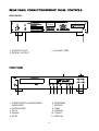
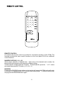
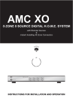
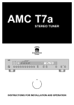
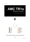
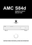
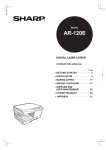
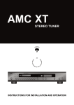
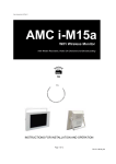
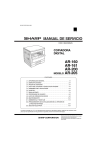
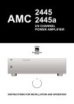
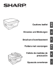
SERVICE SAFETY PRECAUTIONS (UL)
WARNING! INVISIBLE LASER RADIATION WHEN OPEN AND INTERLOCKS DEFEATED.
AVOID EXPOSURE TO BEAM.
VORSICHT! UNSICHTBARE LASERSTRAHLEN TRITT AUS, WENN DECKEL GE FFNET
UND WENN SICHERHEITSVERRIEGELUNG BERBR CKT IST. NICHT DEM STRAHL
AUSSETZEN.
ADVARSEL- USYNLIG LASERSTR LING VED BNING, N R SIKKERHEDSAFBRYDERE
ER UDE AF FUNKTION. UNDG UDS TTELSE FOR STR LUNG.
ADVARSEL- USYNLIG LASERSTR LING N R DEKSEL
BRYTES. UNNG EKSPONERING FOR STR LEN.
PNES OG SIKKERHEDSL S
VARNING- OSYNLIG LASERSTR LNING N R DENNA DEL R PPNAD OCH SP RRAR
R URKOPPLADE. STR LEN R FARLIG.
VARO!- AVATTAESSA JA SUOJALUKITUS OHITETTAESSA OLET ALTTlINA
N KYM T NNT LASERS TEILYLLE. L KATSO S TEESEEN.
1. Use exact replacement parts for critical locations, marked " ".
2. Return lead dress to original position, and re install protective
covers.
3. Before returning to customer, test for shock hazard; use either
method A or B:
A. Leakage test, "cold":
1. Unplug AC cord; turn power switch ON.
2. Connect one lead of High Voltage Insulation Tester to both
prongs of AC plug.
3. Touch other lead to all exposed metal parts.
4. Impedance measurement must be 0.3-5.0 Megohms.
B. Leakage test, "live":
1. Plug unit directly into AC outlet; do not use isolation transformer.
2. Connect one lead of Leakage Current Tester to earth ground.
3. Touch other lead to all exposed metal parts.
4. Leakage measurement must be less than 0.5 milliamps.
CLASS 1 LASER PRODUCT
LUOKAN 1 LASERPLAITE
KLASS 1 LASERAPPARAT
CAUTION: FOR CONTINUED PROTECTION AGAINST RISK OF FIRE, REPLACE ONLY WITH THE SAME
TYPE OF T800mA/250V FUSES.
ATTENTION: POUR MAINTENIR PROTECTION CONTRE RISQUE D'INCENDIE, UTILISER LES FUSIBLES
DE RECHANGE DE MEME TYPE DE T800mA/250V.
THIS DIGITAL APPARATUS DOES NOT EXCEED THE CLASS B LIMITS FOR RADIO NOISE EMISSIONS
FROM DIGITAL APPARATUS AS SET OUT IN THE RADIO INTERFERENCE REGULATIONS OF THE
CANADIAN DEPARTMENT OF COMMUNICATIONS.
LE PRESENT APPAREIL NUMVERIQUE N'EMET PAS DE BRUITS RADIOELECTRIQUES DEPASSANT
LES LIMITES APPLICABLES AUX APPAREILS NUMERIQUES DE LA CLASSE B PRESCRITES DANS LE
REGLEMENT SUR LE BROUILLAGE RADIO ELECTRIQUE EDICTE PAR LE MINISTERE DES
COMMUNICATIONS DU CANADA.
THIS DEVICE COMPLIES WITH PART 15 OF THE FCC RULES. OPERATION IS SUBJECT TO THE
FOLLOWING TWO CONDITIONS:
(1) THIS DEVICE MAY NOT CAUSE HARMFUL INTERFERENCE, AND
(2) THIS DEVICE MUST ACCEPT ANY INTERFERENCE RECEIVED, INCLUDING INTERFERENCE THAT
MAY CAUSE UNDESIRED OPERATION.
2
FEATURES OF THE AMCTM MODEL CD8b
* The AMC model CD8b was designed to meet professional quality performance
standards and to provide superior value.
* Select grade components are utilized throughout the circuit design with special
emphasis on components within the audio path to assure stable, consistent performance.
* Premium transport and servo drive system assures constant data rate retrieval and
unsurpassed tracking performance.
* Use Burr Brown 96kHz/24bit D/A converter for high resolution and superb audio
reproduction.
* Unique 5-pole linear active LPF (low pass filter) prevents interference from ultrasonic
noise commonly found in other CD playback systems.
* Advanced power supply design incorporates separate windings for the digital, analog
and servo circuits to prevent interference and preserve sonic performance.
* EIA calibrated audio outputs ensure a proper match with preamplifiers and receivers.
* Provide digital output allow the CD8b to be used as a high-quality transport and provide
for future upgrades.
* Up to 21 tracks may be programmed to playback in desired order.
* Full-function infrared (IR) remote control with direct track access.
TRANSIT SCREW
A transit screw secures the
transport mechanism for protection
during shipment.
Before making
any connections or applying power
to the CD6b, remove the transit
screw which is located on the
underside of the unit.
3
REAR PANEL
1
3
2
1. AUDIO OUTPUT
2. DIGITAL OUTPUT
3. AC LINE CORD
10
11
1
2
1. POWER SWITCH AND POWER
INDICATOR
2. OPEN/CLOSE
3. PLAY
4. PAUSE
5. STOP
3
4
5
6. PROGRAM
7. REPEAT
8. TIME
9. SEARCH
10. TRACK
11. DISPLAY
4
6
7
8
9
1. AUDIO OUTPUT
Connect the left and right channel
unbalanced (RCA) audio outputs to any
input on your preamplifier or receiver
except "Phono" or "Turntable". Highquality interconnection cables are
recommended.
2. DIGITAL OUTPUT
Co-axial cable digital output.
3. AC LINE CORD
Plug the AC line cord into a switched outlet
on your amplifier or into any AC wall
outlet that provides the correct line voltage.
5
1. POWER SWITCH
The CD player is turned on by depressing
the power switch. The LED indicator
above the power switch will glow green.
Note: All connections must be
completed before turning the power on.
a) Use the TRACK button to select the first
track in your planned sequence. In
the memory mode, the CD8b has a "wraparound" function. If you TRACK back
repeatedly from track "00", the number
counts down from the final track of the disc.
This provides a convenient way to select
high-numbered tracks during
programming.
b) Press PROGRAM to store the selected
track in memory. The track number
will revert back to "00" and the time display
will advance to "P:02", showing the
player is ready for a second entry.
c) Repeat steps a and b, TRACK and
PROGRAM, to select and store other
track numbers in memory, up to a
maximum of 21 entries.
d) At any point during the program entry
process, the TIME button on the player
can be pressed to display the total playing
time of the program.
e) To review programmed entries, press
PROGRAM repeatedly to show
programmed entries. When the displayed
track number returns to "00",
additional tracks may be entered in the
memory by repeating steps a and b.
f) To play the stored programs, press
PROGRAM followed by PLAY. The word
PROGRAM will appear in the upper-right
corner of the display indicating that a stored
program is being played.
During program playback the TRACK
buttons will access only the tracks in the
program list. If you want to skip over a
portion of a stored program, initiate play
and press TRACK to jump over the
programmed tracks you don't want to hear.
g) To terminate the programmed play,
press STOP. The TRACK and SEARCH
buttons will now access any track on the
disc. The stored track list , however, still
remains in the memory. If you want to play
the program again, simply press
PROGRAM followed by PLAY. If you want
to add new tracks to the program, press
PROGRAM repeatedly to review the list
until the track number shows "00".
2. OPEN/CLOSE
By pressing the open/close button the disc
drawer will open. Pressing it again
will close the drawer. If the drawer is
opened while a disc is playing, the disc will
stop and the drawer will open. An open
drawer can also be closed by pressing
PLAY or by gently pushing the drawer
inward. If the OPEN/CLOSE button is
pushed after programming the player, all
programming will be erased.
3. PLAY
Place a CD into the open drawer with the
label facing up. Press the PLAY button to
close the drawer and begin playback.
Playback will stop when the STOP button is
pressed or when the disc has reached the
end.
4. PAUSE
While the disc is playing, press the PAUSE
button to suspend playback. Press
the PAUSE button again to resume
playback.
5. STOP
To stop the CD while playing, press the
STOP button. Pressing the STOP button
will cancel any repeat-play cycles and the
display will show the number of the
tracks and total time on the disc.
6. PROGRAMMING
The CD8b can be programmed to play up
to 21 tracks in any desired order.
To program playback, start by pressing the
PROGRAM button.
The MEMORY
indicator will illuminate. When the track
number displays "00" and the time display
indicates "P:01" programming entries may
be entered.
6
h) To clear the program memory, press
OPEN/CLOSE to open the drawer or
simply switch off the power.
10. TRACK
Press TRACK (< or >) to find a desired
track. Track number is displayed.
7. REPEAT
This button will allow two different types of
endless play modes.
Press the REPEAT button once, the word
REPEAT 1 will appear on the display
and the selected track will be repeated
endlessly until the STOP button is
pressed.
Press the REPEAT button a second time,
the word REPEAT ALL will appear and the
entire disc will repeat until the STOP button
in pressed.
Press the REPEAT button a third time or
press the STOP button to cancel
REPEAT mode. The display and operation
will return to normal.
11. DISPLAY
When loading a disc and using the
OPEN/CLOSE button to close the disc
drawer, the TOC (Table of Contents) of the
disc will be read and the display will show
the number of tracks and the total playing
time of all of he tracks on the disc. During
play, the following information is displayed:
Track Number
These track numbers are identified on the
CD package and are encoded in the
disc by the manufacturer.
Time
Shows in minutes and seconds the time
elapsed in the music since the
beginning of the current track. Pressing
the TIME button will display the time
remaining until the end of the current track
or the playing time remaining until the
end of the disc.
8. TIME
The TIME button will cycle the time display
through three different modes.
a. TIME: the elapsed time since the
beginning of the current track, in minutes
and seconds. ( This is the "default" setting,
selected automatically when the player is
turned on).
b. REMAIN: (track number displayed):
shows the total playing time that remains till
the end of the current track.
c. REMAIN: (track number blank): The total
playing time that remains till the end of the
disc. During program play, the remaining
time of the program is shown. During
program entry, the TIME button displays
the total playing time of the tracks in the
program.
Status
>
Explanation
glows to indicate disc is
playing.
II
glows to indicate that a disc
cannot be read.
REPEAT 1
glows during repeat play of a
single track.
REPEAT ALL glows during repeat play of
the entire disc.
REPEAT AB glows during repeat play
from point A to point B.
REMAIN
glows to indicate number of
tracks on disc being loaded
or the tracks that have been
programmed into memory.
The number of the track that
is playing will flash.
OVER
glows when the disc
contains more than 16
tracks.
9. SEARCH
Press and hold SEARCH (<< or >>) to find
a desired starting point or a certain
part of a track. When the SEARCH button
is pressed and held during playback
the output level will be automatically
attenuated by 12dB.
7
REMOTE CONTROL
An infrared (IR) remote control is provided for convenient operation of the CD8b. The
handset provides the same control functions as the front panel PLUS two additional
control functions.
NUMERIC KEYPAD (1-10, +10)
Allows direct selection of desired track. Upon entry of the desired track number, the
player shifts to the beginning of the track and begins to play.
To select track 8, simply press the "8" button. To select track 24, press the "+10" button
twice and then press the "4" button ( +10, +10, 4 ).
RANDOM
Pressing the RANDOM button before or during play will cause the CD8b to play all tracks
on the disc in a random order until all tracks have been played. To cancel random play,
simply press the RANDOM button again.
8
AUDIO OUTPUT (Ref. 1KHz/0dB, unless otherwise stated):
Disc capacity.............................................................................Single disc, 120 or 80mm
Programming capability.....................................................................................21 Tracks
Digital to analogue convertion..............................Enhanced multilevel Delta-Sigma DAC
Digital filter.....................................................8X over-sampling at a 96Khz sampling rate
(Stop band attenuation:82dB, passband ripple: +/-0.002dB)
Analogue filter..............................................................................................5-Pole active
Frequency response 5Hz-20KHz.....................................................................<+/-0.3 dB
De-Emphasis error...........................................................................................<+/-0.3 dB
Linearity...........................................................................................+/-0.5 dB: 0 to -90 dB
Channel separation (20Hz to 20KHz)..................................................................>90 dB
Channel imbalance..........................................................................................<+/-0.2 dB
S/N ratio (Aweighted, measured with all zeros test disc).........................................105 dB
Dynamic range....................................................................................................>100 dB
THD (at 0dB, 1KHz, Aweighted)........................................................0.0018% (-94.9 dB)
Intermodulation distortion (19 & 20 KHz).............................................................<100 dB
Output impedance..............................................................................................120 ohm
Output level at 0dB............................................................................................2.2 Vrms
Digital error correction..........................................................................CIRC with double
error correction in C1 and C2
Wow and flutter.......................................................................................Unmeasureable
(Quartz crystal accuracy)
Remote control unit..................................................Full functional with numeric keypad
S/PDIF DIGITAL OUTPUT:
Digital Output level.......................................................................................0.5 Vpp
Load impedance...................................................................................................75 ohm
Peak emission wave length...................................................................................660 nm
PHYSICAL:
Dimensions (W x H x D).........................................................................430x82x300 mm
Net weight............................................................................................................6.5 Kgs
Shipping weight (4 pieces)..................................................................................28.5 Kgs
Power consumption..................................................................................................30 W
Weltronics Corp. reserved the right to improve its products at any time. Specifications are
subject to change without notice.
9
1. READ INSTRUCTIONS
16. DAMAGE REQUIRING SERVICE
All the safety and operating instructions should be read
before the appliance is operated.
2. RETAIN INSTRUCTIONS
The safety and operating instructions should be retained for
future reference.
3. HEED WARNINGS
All warnings on the appliance and in the operating instructions
should be adhered to.
4. FOLLOW INSTRUCTIONS
All operating and use instructions should be followed.
5. WATER AND MOISTURE
The appliance should not be used near water - for example,
near a bathtub, washbowl, kitchen sink, laundry tub, in a wet
basement, or near a swimming pool, etc.
6. CARTS AND STANDS
The appliance should be used only with a cart or stand that is
recommended by the manufacturer.
6A. An appliance and cart combination should be
moved with care. Quick stops, excessive force,
and uneven surfaces may cause the appliance
and cart combination to overturn.
7. WALL OR CEILING MOUNTING
PORTABLE CART WARNING
S3125A
This equipment is not designed for use mounted on a wall or a
ceiling.
8. VENTILATION
The appliance should be situated so that its location or position
does not interfere with its proper ventilation. For example, the
appliance should not be situated on a bed, sofa, rug, or similar
surface that may block the ventilation openings, or placed in a
built-in installation, such as bookcase or cabinet that may
impede the flow of air through the ventilation openings.
9. HEAT
The appliance should be situated away from heat sources
such as radiators, heat registers, stoves, or other appliances
(including amplifiers) that produce heat.
The appliance should be serviced by qualified service
personnel when:
a) The power-supply cord or the plug has been damaged; or
b) Objects have fallen, or liquid has been spilled into the
appliance; or
c) The appliance has been exposed to rain; or
d) The appliance does not appear to operate normally or
exhibits a marked change in performance; or
e) The appliance has been dropped, or the enclosure is
damaged.
17. POWER LINES
(APPLIES TO TUNER AND RECEIVERS ONLY)
An outdoor antenna should be located away from power lines.
18. OUTDOOR ANTENNA GROUNDING
(APPLIES TO TUNER AND RECEIVERS ONLY)
If an outside antenna is connected to the receiver, be sure the
antenna system is grounded so as to provide some protection
against voltage surges and built up static charges.
Section 810 of the National Electrical Code, ANSI/NFPA No.
70-1984, provides information with respect to proper
grounding of the mast and supporting structure, grounding of
the lead-in wire to an antenna discharge unit, size of grounding
conductors, location of antenna-discharge unit, connection to
grounding electrodes, and requirements for the grounding
electrode. See Figure.
a) Use No. 10 AWG (5.3 mm2) copper, No. 8 AWG (8.4 mm2)
aluminum, No. 17 AWG (1.0 mm2) copper-clad steel or
bronze wire, or larger, as a ground wire.
b) Secure antenna lead-in and ground wires to house with
stand-off insulators spaced from 4-6 feet (1.22-1.83 m)
apart.
c) Mount antenna discharge unit as close as possible to where
lead-in enters house.
d) Use jumper wire not smaller than No.6 AWG (13.3 mm2)
copper, or the equivalent, when a separate antennagrounding electrode is used. See NEC Section 810-21(j).
Antenna Grounding According to
the National Electrical Code
10. POWER SOURCES
The appliance should be connected to a power supply only of
the type described in the operating instructions or as marked
on the appliance.
Antenna Lead
In Wire
11. POWER-CORD PROTECTION
Power-supply cords should be routed so that they are not likely
to be walked on or pinched by items placed upon or against
them, paying particular attention to cords at plugs,
convenience receptacles, and the point where they exit from
the appliance
12. CLEANING
The appliance should be cleaned only as recommended by
the manufacturer.
Ground
Clamp
Electric
Service
Equipment
The power cord of the appliance should be unplugged from the
outlet when left unused for a long period of time.
Power Service Grounding
Electrode System
(NEC Art 250 Part H)
14. OBJECT AND LIQUID ENTRY
15. SERVICING
The user should not attempt to service the appliance beyond
that described in the operating instructions. All other servicing
should be referred to qualified service personnel.
Grounding Conductors
(NEC Section 810.21)
Ground Clamps
13. NON USE PERIODS
Care should be taken so that objects do not fall and liquids are
not spilled into the enclosure through openings.
Antenna
Discharge
Unit (NEC
Section 810.20)
National Electrical Code
Available from Library, book
stores, or National Fire Protection
Association (Batterymarch Park,
Quincy. MA 02269).
AMC 21-3004
PN: 21-4136