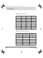
1
3000/4000 UM : Front Cover Page 1 Wednesday, September 4, 1996 8:28 AM Ultre 3000/4000 Imagesetter Ultre 4000 ULTRE a division of Linotype-Hell Company This document was created with FrameMaker 4.0.4 3000/4000 UM : Copyright Page 4 Wednesday, September 4, 1996 8:28 AM Copyright 1995 Ultre, a division of Linotype-Hell Company No part ofand this Linotronic book may be prior of written Linotype arereproduced registered without trademarks Lino-permission. type-Hell AG. Important notice! We are dedicated to improving and enhancing the hardware and software of our typesetting and communication systems and equipment. Consequently, the information in this manual is subject to change without notice. Reference is made to this fact during training courses. The contents of this documentation are correct at the time of going to press. We point out that companies, trademarks and product names mentioned in this manual fall within the regulations regarding protection of trademarks and patents. Other product names and brands not expressly mentioned in this manual are trademarks or registered trademarks of the corresponding manufacturers. The information contained in this manual about performance and speed as well as technical data concerning application of our products is not legally binding as it does not constitute a written contract of features. Ultre is registered trademarks of the Ultre division of LinotypeHell Company. Edition March 1995 This document was created with FrameMaker 4.0.4 3000/4000 UM : 3000/4000 UMTOC Page I Wednesday, September 4, 1996 8:28 AM Table of Contents Before You Start Notes on this Documentation . . . . . . . . . . . . . . . . . . . . . . . . . I 1 Notes on Technical Safety 1-1 Correct Use . . . . . . . . . . . . . . . . . . . . . . . . . . . . . . . . . . . .1-3 General Information . . . . . . . . . . . . . . . . . . . . . . . . . . . . . .1-3 Cleaning the Unit . . . . . . . . . . . . . . . . . . . . . . . . . . . . . . . .1-4 Laser Safety . . . . . . . . . . . . . . . . . . . . . . . . . . . . . . . . . . . .1-5 Radio Interference . . . . . . . . . . . . . . . . . . . . . . . . . . . . . . .1-8 Safety Information . . . . . . . . . . . . . . . . . . . . . . . . . . . . . . .1-9 2 Introduction 2-1 Product Description . . . . . . . . . . . . . . . . . . . . . . . . . . . . . .2-3 Installation . . . . . . . . . . . . . . . . . . . . . . . . . . . . . . . . . . . . .2-4 3 Control Panel 3-1 Push Button Controls . . . . . . . . . . . . . . . . . . . . . . . . . . . . .3-4 LCD . . . . . . . . . . . . . . . . . . . . . . . . . . . . . . . . . . . . . . . . . .3-7 LED. . . . . . . . . . . . . . . . . . . . . . . . . . . . . . . . . . . . . . . . . .3-10 Machine Operation . . . . . . . . . . . . . . . . . . . . . . . . . . . . . .3-11 4 Loading 4-1 Loading Photo Material. . . . . . . . . . . . . . . . . . . . . . . . . . . .4-3 Preparing the Bulk Load Supply Cassette . . . . . . . . . . . .4-10 Using Paper Photo Materials . . . . . . . . . . . . . . . . . . . . . .4-11 5 Changing Default Settings 5-1 Menus and Functions . . . . . . . . . . . . . . . . . . . . . . . . . . . . .5-4 Density . . . . . . . . . . . . . . . . . . . . . . . . . . . . . . . . . . . . . . . .5-5 LCD Adjustments . . . . . . . . . . . . . . . . . . . . . . . . . . . . . . . .5-6 Set Default Resolution . . . . . . . . . . . . . . . . . . . . . . . . . . . .5-7 Ultre 3000/4000 - User Manual This document was created with FrameMaker 4.0.4 I 3000/4000 UM : 3000/4000 UMTOC Page II Wednesday, September 4, 1996 8:28 AM Table of Contents Set Laser Power Multiplier (LPM). . . . . . . . . . . . . . . . . . . . 5-8 Set Laser Power Range (LPR). . . . . . . . . . . . . . . . . . . . . . 5-8 Set Film Advance Length . . . . . . . . . . . . . . . . . . . . . . . . . . 5-9 Print Test . . . . . . . . . . . . . . . . . . . . . . . . . . . . . . . . . . . . . 5-10 Reverse Feed. . . . . . . . . . . . . . . . . . . . . . . . . . . . . . . . . . 5-11 Buffer Mode . . . . . . . . . . . . . . . . . . . . . . . . . . . . . . . . . . . 5-11 6 Messages 6-1 LCD Status Messages . . . . . . . . . . . . . . . . . . . . . . . . . . . . 6-3 Error Messages and Corrective Procedures . . . . . . . . . . . 6-5 7 II Technical Data 7-1 Edition March 1995 3000/4000 UM : BeforeYouStart Page I Wednesday, September 4, 1996 8:28 AM Before You Start This manual Before Youcovers Startthe operation of the Imagesetter Ultre 3000/4000 The words film, photo material, and material are used interchangeably throughout this manual. Unless otherwise indicated, these words refer to any photo material that is suitable for use in the Ultre 3000 and 4000 imagesetters. ■ Notes on this Documentation This documentation contains: ● Notes on Technical Safety ● Introduction (with Installation) ● Control Panel Description of control panel (push button controls and LCD display) and machine operation ● Loading Photographic Material (incl. preparing of the bulk load supply cassette) ● Change Default Settings ● Messages Status and error messages incl. corrective procedures ● Technical Data Ultre 3000/4000 - User Manual This document was created with FrameMaker 4.0.4 I 3000/4000 UM : BeforeYouStart Page II Wednesday, September 4, 1996 8:28 AM Notes on this Documentation ■ Additional Documentation You will find additional information in the following documentation: ● ■ II RIP Manual Symbols in this Documentation 3 The text contains information which must be observed in order to protect the user from danger! 2 This information must be observed to protect the equipment, the software and the data from being damaged! 1 The text contains general or additional information about a certain subject. Edition March 1995 3000/4000 UM : Chapter 1 (Safety) Page 1 Wednesday, September 4, 1996 8:28 AM 1 Notes on Technical Safety 1 Correct Use . . . . . . . . . . . . . . . . . . . . . . . . . . . . . . . . . . . . . . . . . . . 1-3 General Information . . . . . . . . . . . . . . . . . . . . . . . . . . . . . . . . . . . . 1-3 Cleaning the Unit . . . . . . . . . . . . . . . . . . . . . . . . . . . . . . . . . . . . . . 1-4 Laser Safety . . . . . . . . . . . . . . . . . . . . . . . . . . . . . . . . . . . . . . . . . . 1-5 Standards and Regulations . . . . . . . . . . . . . . . . . . . . . . . . . . . . . . . 1-5 Service . . . . . . . . . . . . . . . . . . . . . . . . . . . . . . . . . . . . . . . . . . . . . . 1-5 Position of Laser Safety Labels . . . . . . . . . . . . . . . . . . . . . . . . . . . . 1-7 Radio Interference . . . . . . . . . . . . . . . . . . . . . . . . . . . . . . . . . . . . . 1-8 Notes for Users in the US . . . . . . . . . . . . . . . . . . . . . . . . . . . . . . . . 1-8 Notes for Users in Canada . . . . . . . . . . . . . . . . . . . . . . . . . . . . . . . 1-8 Safety Standards . . . . . . . . . . . . . . . . . . . . . . . . . . . . . . . . . . . . . . 1-9 Electrical Safety . . . . . . . . . . . . . . . . . . . . . . . . . . . . . . . . . . . . . . . . 1-9 Mechanical Safety . . . . . . . . . . . . . . . . . . . . . . . . . . . . . . . . . . . . . . 1-9 General Safety . . . . . . . . . . . . . . . . . . . . . . . . . . . . . . . . . . . . . . . . 1-9 Electromagnetic Compatibility . . . . . . . . . . . . . . . . . . . . . . . . . . . . . 1-9 Approvals . . . . . . . . . . . . . . . . . . . . . . . . . . . . . . . . . . . . . . . . . . . . 1-10 Ultre 3000/4000 - User Manual This document was created with FrameMaker 4.0.4 1-1 3000/4000 UM : Chapter 1 (Safety) Page 3 Wednesday, September 4, 1996 8:28 AM Notes on Technical Safety - 1 The equipment meets the standard safety regulations for information technology equipment including electrical office equipment. ■ Correct Use The Ultre 3000/4000 is a laser imagesetter for photographic material and is only to be used for this purpose in accordance with the user documentation. Do not place any objects or liquids on the unit. Ventilation outlets must be kept clear at all times. ■ General Information Pay attention to the notes on ambient conditions in Chapter 7, Technical Data, and to the conditions for installing the unit in Chapter 2, Introduction, part Installation. Unit connectors and sockets must be easily accessible. This is important as, in the event of a danger, the unit is to be completely disconnected from the power by pulling out the mains plug. Ultre 3000/4000 - User Manual 1-3 3000/4000 UM : Chapter 1 (Safety) Page 4 Wednesday, September 4, 1996 8:28 AM 1 - Notes on Technical Safety The unit does not contain any parts which require servicing by the operator. 3 ATTENTION: Unauthorized opening of the cabinet or improper repairs can expose the operator to great danger. Service work may only be performed by authorized personnel specialized in this field. The appropriate regulations for the prevention of accidents are to be adhered to when the equipment is serviced. Failure to observe the safety regulations may result in the loss of accident insurance! ■ Cleaning the Unit 3 The unit must be disconnected from the power supply by pulling out the mains plug if cleaning the unit involves using liquids. The unit surfaces can be cleaned using a dry cloth. If the unit is very dirty, it may be cleaned with a damp cloth which has been dipped in washing-up liquid and well drained. Make sure that no liquid gets inside the unit and keep moisture away from the connection sockets at the rear of the unit. 2 1-4 Never use abrasive cleansings or solvents! Edition March 1995 3000/4000 UM : Chapter 1 (Safety) Page 5 Wednesday, September 4, 1996 8:28 AM Notes on Technical Safety - 1 ■ Laser Safety ■ Standards and Regulations The Ultre 3000/4000 Laser Imagesetter is certified as a Class 1 laser product under the U.S. Department of Health and Human Services (DHHS) Radiation Performance Standard according to the Radiation Control for Health and Safety Act of 1968. As such, this unit complies with 21 CFR Chapter 1, Sub-chapter J. This means that this laser imagesetter does not emit hazardous laser radiation. Since radiation emmitted inside the laser imagesetter is completely confined within protective housings and external covers, the laser beam cannot escape from the machine during any phase of user operation or maintenance. ■ Service None of the parts within the protective housing require servicing by the user. Any servicing only must be done by factory-trained service technicians authorized by Linotype-Hell. 3 Ultre 3000/4000 - User Manual CAUTION: Do not remove the cover or housing of the imagesetter. Otherwise there is a risk that you will be exposed to invisible laser radiation or injured by an electrical shock. 1-5 3000/4000 UM : Chapter 1 (Safety) Page 6 Wednesday, September 4, 1996 8:28 AM 1 - Notes on Technical Safety 3 1-6 CAUTION: Use of controls or adjustments, or performance of procedures other than those specified herein, may result in hazardous radiation exposure Edition March 1995 3000/4000 UM : Chapter 1 (Safety) Page 7 Wednesday, September 4, 1996 8:28 AM Notes on Technical Safety - 1 ■ Position of Laser Safety Labels ■ Laser Label 1 in English and German on the unit Rear Side. CLASS 1 LASER LASER KLASSE 1 ■ Laser safety labels internal to the unit on the optical casting assembly. VORSICHT LASERTRAHLUNG, WENN ABDECKUNG GEÖFFNET NICHT IN DEN STRAHL BLICKEN AUCH NICHT MIT OPTISCHEN INSTRUMENTEN CAUTION INVISIBLE LASER RADIATION WHEN OPEN AVOID DIRECT EXPOSURE TO TO BEAM Avoid Exposure Invisible LASER radiation is emitted from this aperature DANGER Invisible Laser radiation is emitted when open. AVOID DIRECT EXPOSURE TO BEAM. Ultre 3000/4000 - User Manual 1-7 3000/4000 UM : Chapter 1 (Safety) Page 8 Wednesday, September 4, 1996 8:28 AM 1 - Notes on Technical Safety ■ Radio Interference ■ 2 Notes for Users in the US This equipment generates, uses and can radiate radio frequency energy and if not installed and used in accordance with the instructions manual, may cause interference to radio communications. It has been tested and found to comply with the limits for a Class A computing device pursuant to Subpart B of Part 15 of FCC rules, which are designed to provide reasonable protection against such interference when operated in a commercial environment. Operation of this equipment in a residential area is likely to cause interference in which case, the user at his own expense, will be required to take whatever measures may be required to correct the interference. ■ Notes for Users in Canada This digital apparatus does not exceed the Class A limits for radio noise emissions from digital apparatus set out in the radio interference regulations of the Canadian Department of Communications. Le persent apparil numerique n'emet pas de bruits radio electriques depassant les limites applicables aux appareils numeriques de la Classe A prescrites dens le reglement sue le brouillage radio electrique edicte par le ministre des communications du Canada. 1-8 Edition March 1995 3000/4000 UM : Chapter 1 (Safety) Page 9 Wednesday, September 4, 1996 8:28 AM Notes on Technical Safety - 1 ■ Safety Information ■ ● EN 60950 (Europe) ● UL 1950 (USA) ● CSA C22.2 No, 950 (Canada) ● DIN 31000/31001 (Germany) ■ ● ■ Ultre 3000/4000 - User Manual Electrical and Mechanical Safety Laser Safety EN 60825 Complies with 21 CFR 1040.10 and 1040.11 Electromagnetic Compatibility ● FCC Part 15, Subpart B, Class A (USA) ● DOC Radio Act SOR/88-475, Class A (Canada) 1-9 3000/4000 UM : Chapter 1 (Safety) Page 10 Wednesday, September 4, 1996 8:28 AM 1 - Notes on Technical Safety ■ ● ■ 1-10 Electromagnetic Interference EN 50081-2 IEC 801-2 IEC 801-3 IEC 801-4 Approvals ● CE (Europe) ● ETL (USA) ● ETL-C (Canada) Edition March 1995 3000/4000 UM : Chapter 2 (Intro) Page 1 Wednesday, September 4, 1996 8:28 AM 2 Introduction 2 Product Description . . . . . . . . . . . . . . . . . . . . . . . . . . . . . . . . . . . 2-3 Installation . . . . . . . . . . . . . . . . . . . . . . . . . . . . . . . . . . . . . . . . . . . 2-4 General Information . . . . . . . . . . . . . . . . . . . . . . . . . . . . . . . . . . . . . 2-4 Mains Connection . . . . . . . . . . . . . . . . . . . . . . . . . . . . . . . . . . . . . . 2-5 Power Cord Instruction . . . . . . . . . . . . . . . . . . . . . . . . . . . . . . . . . . 2-6 Note for Installations in the UK . . . . . . . . . . . . . . . . . . . . . . . . . . . . 2-7 Data Connection . . . . . . . . . . . . . . . . . . . . . . . . . . . . . . . . . . . . . . . 2-7 On/Off Switch . . . . . . . . . . . . . . . . . . . . . . . . . . . . . . . . . . . . . . . . . 2-8 Ultre 3000/4000 - User Manual This document was created with FrameMaker 4.0.4 2-1 3000/4000 UM : Chapter 2 (Intro) Page 3 Wednesday, September 4, 1996 8:28 AM Introduction - 2 ■ Product Description The Ultre 3000/4000 is a high-resolution raster scanning device for producing typesetting, graphic images, photographs, and tonal areas on silver photographic material. The light source is a laser diode operating in the near infra-red (780nm). Resolution is selectable, but normal operation is at 1200 or 2400 lines per inch. 1 Ultre 3000/4000 - User Manual The Ultre 3000/4000 is strictly an output device. It requires a Raster Image Processor (RIP) to break images into sequential rasters (video data) ready for imagesetting. 2-3 3000/4000 UM : Chapter 2 (Intro) Page 4 Wednesday, September 4, 1996 8:28 AM 2 - Introduction ■ Installation ■ General Information The unit is to be connected to the power supply via the power cable included in the delivery. Pay attention to all warnings and instructions labeled or printed on the unit. Electric circuit The Ultre 3000/4000 Imagesetters are intended for operation in a single-phase electric circuit with a grounded neutral conductor. Do not connect the units to other types of electric circuits. Make sure, that mains voltage and frequency of your power supply match with mains voltage and frequency as indicated on the serial number plate of the unit. Installing The unit should not be installed near air conditioning equipment and is to be protected from humidity and direct sunlight. Unit sockets and connection sockets should be near the unit and always be easily accessible. Ventilation Take care that the unit is installed at a sufficient distance from the walls (min. 80 cm) and other objects so that adequate ventilation can be ensured. Ventilation outlets must be kept clear at all times. The terminals located at the rear of the unit should be accessible. If the unit is brought from a cold environment into the operation room, condensation can occur. In this case, the unit should be stored in the operation room for a minimum of six hours to aclimatize it. 2-4 Edition March 1995 3000/4000 UM : Chapter 2 (Intro) Page 5 Wednesday, September 4, 1996 8:28 AM Introduction - 2 ■ Mains Connection The Imagesetter can be connected to mains supplies as indicated on the unit serial number plate (nominal input 115 V or 230 V AC, 50 or 60 Hz). The unit power supply will automatically be switched to the matching supply voltage and frequency. To connect the unit to the mains supply, use the power cord set provided with the unit or refer to the tables following to select a commercially available cord as specified. 3 Ultre 3000/4000 - User Manual Switching off the Imagesetter from the rear panel does not disconnect the unit from the mains supply. To disconnect the Ultre 3000/4000 from the mains supply, remove the power plug first. The mains outlet must be easily accesible. 2-5 3000/4000 UM : Chapter 2 (Intro) Page 6 Wednesday, September 4, 1996 8:28 AM 2 - Introduction ■ Power Cord Instruction If you will be using the 100-120 volts power source voltage, be sure to refer to the following list. Plug Configuration Plug Type Voltage Reference Standards Power Cord North America 125V 10A 115120V ANSI C73.11 NEMA 5-15-P IEC 83 UL Listed, CSA Certified Type SJT, 18AWG If you will be using the 200-240 volts power source voltage, be sure to refer to the following list. Plug Configuration 2-6 Plug Type Voltage Reference Standards Power Cord Europe 250V 10/16A 230V CEE(7).II IV.VII IEC 83 IEC 127 <HAR> H05VV-F United Kingdom 240V 6A 220240V B.S. 1363 IEC 83 IEC 127 <HAR> H05VV-F Australia 240V 10A 240250V A.S. C112 IEC 127 <HAR> H05VV-F North America 250V 15A 240V ANSI C73.20 NEMA 6-15-P IEC 83 UL 198.6 UL Listed, CSA Certified Type SJT, 18AWG Edition March 1995 3000/4000 UM : Chapter 2 (Intro) Page 7 Wednesday, September 4, 1996 8:28 AM Introduction - 2 ■ 3 The cores in the main leads are colored in accordance with the following codes: ● green and yellow earth ● blue neutral ● brown live ■ 3 Note for Installations in the UK Data Connection CAUTION: Connect the cables with the power off! Only use shielded cables in keeping with the radio interference suppression regulations! The rear of the unit has 3 connectors consisting of the LinotypeHell Interface Connector, the Small computer Standard Interface (SCSI), and an external RS232 port (see page 2-9). Interface Connector Input data is connected to the Interface Connector. It is a 37 pin "D" connector. SCSI The SCSI is an optional interface. If it is utilized, then standard 50 connector SCSI-1 cable is utilized for the connection to the RIP. RS232 The external RS232 port is used for external diagnostics which are not implemented in the current release of the Imagesetter. Ultre 3000/4000 - User Manual 2-7 3000/4000 UM : Chapter 2 (Intro) Page 8 Wednesday, September 4, 1996 8:28 AM 2 - Introduction ■ On/Off Switch Power is controlled by the rocker switch located on the back panel above the power supply connector. When power is turned on, the machine will perform a brief diagnostic self-test. It will signal that it is ready by illuminating the green light emitting diode (LED) on the control panel and displaying "READY" on the liquid crystal display's (LCD) status line (LCD Display see page 3-3). Serial I/F Port SCSI I/F Port On/Off Switch Ultre Interface Connector 2-8 Power Connector Edition March 1995 3000/4000 UM : Chapter 3 (Controls) Page 1 Wednesday, September 4, 1996 8:28 AM 3 Control Panel 3 Push Button Controls . . . . . . . . . . . . . . . . . . . . . . . . . . . . . . . . . . 3-4 Jog Button . . . . . . . . . . . . . . . . . . . . . . . . . . . . . . . . . . . . . . . . . . . . 3-4 Film Advance Button . . . . . . . . . . . . . . . . . . . . . . . . . . . . . . . . . . . . 3-4 Cut Button . . . . . . . . . . . . . . . . . . . . . . . . . . . . . . . . . . . . . . . . . . . . 3-5 Density Button . . . . . . . . . . . . . . . . . . . . . . . . . . . . . . . . . . . . . . . . . 3-5 Menu Button . . . . . . . . . . . . . . . . . . . . . . . . . . . . . . . . . . . . . . . . . . 3-5 Arrow Buttons . . . . . . . . . . . . . . . . . . . . . . . . . . . . . . . . . . . . . . . . . 3-6 Enter Button . . . . . . . . . . . . . . . . . . . . . . . . . . . . . . . . . . . . . . . . . . 3-6 Reset Button . . . . . . . . . . . . . . . . . . . . . . . . . . . . . . . . . . . . . . . . . . 3-6 LCD . . . . . . . . . . . . . . . . . . . . . . . . . . . . . . . . . . . . . . . . . . . . . . . . . 3-7 Machine Status Display . . . . . . . . . . . . . . . . . . . . . . . . . . . . . . . . . . 3-7 Density Value Display . . . . . . . . . . . . . . . . . . . . . . . . . . . . . . . . . . 3-10 Menu Selection Display . . . . . . . . . . . . . . . . . . . . . . . . . . . . . . . . . 3-10 LED . . . . . . . . . . . . . . . . . . . . . . . . . . . . . . . . . . . . . . . . . . . . . . . . 3-10 Machine Operation . . . . . . . . . . . . . . . . . . . . . . . . . . . . . . . . . . . . 3-11 Ultre 3000/4000 - User Manual This document was created with FrameMaker 4.0.4 3-1 3000/4000 UM : Chapter 3 (Controls) Page 3 Wednesday, September 4, 1996 8:28 AM Control Panel - 3 The control panel consists of push button controls, a green LED serving as a visual indicator, and an LCD. Together, these controls and indicators serve as a user interface providing machine status information and the ability to change machine default settings. 1 ↵ ✂ 2 1 3 4 1._____ 1._____ 2._____ 2._____ 3_____. 3_____. 7 5 6 LCD Display 7 Arrows Buttons: 8 Enter 2 Jog 9 Reset 3 Film Advance 4 Cut 5 Density 6 Menu Ultre 3000/4000 - User Manual ∅ 8 9 3-3 3000/4000 UM : Chapter 3 (Controls) Page 4 Wednesday, September 4, 1996 8:28 AM 3 - Control Panel ■ Push Button Controls ■ Jog Button The Jog Button permits the manual operation of the film advance. As long as the button is held depressed, the film will advance, the LED will be blinking on and off, and the LCD will display "FILM ADVANCE". Releasing the Jog Button will cause the film to stop advancing, the LED to stop blinking, and the LCD will display "READY". This can be used for added inter-job spacing, for checking on film feeding when reloading film, and for confirmation of the operational status of the drive circuit. During a JOG, the OOMS (Out Of Media Sensor) and the JAM sensor are ignored to allow loading of the film. ■ Film Advance Button Depressing the Film Advance Button will automatically advance the film by the number of inches that has been programmed into the film advance register (See "Changing Default Settings" on page 5-1, for setting film advance length). While the film is advancing, the LED will be blinking and the LCD will display "FILM ADVANCE". When the film has stopped advancing, the LCD will display "READY" and the LED will stop blinking. 3-4 Edition March 1995 3000/4000 UM : Chapter 3 (Controls) Page 5 Wednesday, September 4, 1996 8:28 AM Control Panel - 3 ■ ✂ Cut Button Depressing the Cut Button will activate the motorized knife assembly thereby cutting the film. The cutter cannot be activated while the film is in motion. Following the cut a short film advance will occur during which time the output cassette cannot be removed. When the advance is complete the LCD will display "REMOVE CASSETTE" at which time the output cassette may be removed without loss of exposed film. No further functions can be performed at the control panel until the output cassette has been removed and replaced. ■ Density Button The Density Button is depressed when there is a need to change the current density setting. Using the Right or Left Arrow Button, the density can be increased or decreased while viewing the value on the LCD (See Chapter 5, "Changing Default Settings", for changing Density setting). ■ 1. 2. 3. 1. 2. 3. Ultre 3000/4000 - User Manual Menu Button Depressing the Menu Button will bring up the Menu Selection Display on the LCD which permits the programming and changing of the machine's default settings. Operating the Horizontal and Vertical Arrow Buttons, will display the submenus and functions on the LCD. For each setting that is changed, it is necessary to depress the Enter Button to save the new value. When reprogramming is completed, depress the Menu Button to return to the Machine Status Display. 3-5 3000/4000 UM : Chapter 3 (Controls) Page 6 Wednesday, September 4, 1996 8:28 AM 3 - Control Panel ■ Arrow Buttons The control panel contains Right Arrow, Left Arrow, Up Arrow, and Down Arrow Buttons. These buttons serve dual functions as controls and cursor keys. As controls, they are used for menu selection and density adjustment. They are also used for moving the cursor on the LCD when selecting default values to be changed. ■ Enter Button The Enter Button is depressed after selecting a new density value and for each new setting or value that is selected while in the Menu Selection Display. ■ Reset Button Depressing the Reset Button will re-initialize the system. It will have the same effect as turning the power to the machine off and turning it back on again. The reset function has no effect on the stored default setup values. 2 3-6 WARNING: Depressing the Reset Button during printing will cause the job to abort. Edition March 1995 3000/4000 UM : Chapter 3 (Controls) Page 7 Wednesday, September 4, 1996 8:28 AM Control Panel - 3 ■ LCD The LCD provides the user with machine status information and displays the menus used to change machine default settings and perform other functions. When power is turned on, or the Reset Button is depressed, the LCD will show the Machine Status Display. This display is also the starting point for accessing the Density Value Display and the Menu Selection Display. ■ Machine Status Display The Machine Status Display has five fields consisting of an: ● Alpha Character ● Horizontal Resolution ● Vertical Resolution ● Film Counter ● Status AlphaCharacter Film Counter Ultre 3000/4000 - User Manual Horizontal Resolution Vertical Resolution Status 3-7 3000/4000 UM : Chapter 3 (Controls) Page 8 Wednesday, September 4, 1996 8:28 AM 3 - Control Panel ■ Alpha Character The Alpha Character field is located in the upper left corner. In normal operation this field will be blank but when the machine is being serviced it may display one of the following letters: ● S ● A - Artificial start of line enabled. This mode is used for testing only and should not be seen in normal operation. ● J OOMS, JAM, or NOCASS signals disabled (see Chapter 6, Messages). This mode is used for testing only and should not be seen in normal operation. ■ - - Serial mode active. Horizontal Resolution The Horizontal Resolution field, located on the top line, shows the programmed horizontal resolution in dots per inch (dpi). "H1200", for example, indicates that the horizontal resolution has been set for 1200 dpi (See Chapter 5, "Changing Default Settings", for changing resolution). 3-8 Edition March 1995 3000/4000 UM : Chapter 3 (Controls) Page 9 Wednesday, September 4, 1996 8:28 AM Control Panel - 3 ■ Vertical Resolution The Vertical Resolution Field, located on the top line, shows the programmed vertical resolution in dots per inch (dpi). "V1200", for example, indicates that the vertical resolution has been set for 1200 dpi (See Chapter 5, "Changing Default Settings", for changing resolution). ■ Film Counter The Film Counter Field, located in the lower left corner, increments every one foot and indicates how many feet of film have been put into the Take-up Cassette. The film counter resets every time the film is cut. ■ Status The Status Field, located in the center of the bottom line, indicates the current status of the machine. "READY", for example, indicates that the machine is ready to receive commands from the host system or via the control panel. If the machine is otherwise engaged, the status display might read, "CUT", "FILM ADVANCE", "PRINTING", "REMOVE CASSETTE"; or it might display an error message (See Chapter 6, "Messages", for a description of LCD status messages). Ultre 3000/4000 - User Manual 3-9 3000/4000 UM : Chapter 3 (Controls) Page 10 Wednesday, September 4, 1996 8:28 AM 3 - Control Panel ■ Density Value Display The Density Value Display provides the current density value in percentage. It is called up by depressing the Density Button while the LCD is showing the Machine Status Display. Access is not available from the Menu Selection Display. The first line contains the word "DENSITY" and the value as a signed (+ or -) number. The second line shows the value as a bar graph where each bar represents a 1% increment. See Chapter 5, "Changing Default Settings", for changing the Density setting. ■ Menu Selection Display The Menu Selection Display provides access to all of the submenus and functions, with the exception of density, to permit reprogramming of the machine's default settings. It can be called up on the LCD by depressing the Menu Button while the LCD is showing the Machine Status Display. See Chapter 5, "Changing Default Settings", for making changes to the default settings. ■ LED The green LED will light up when power is turned on. It will also blink continuously as the film is advancing through the machine. 3-10 Edition March 1995 3000/4000 UM : Chapter 3 (Controls) Page 11 Wednesday, September 4, 1996 8:28 AM Control Panel - 3 ■ Machine Operation Power is turned on by depressing the rocker switch on the machine's back panel (see "On/Off Switch" on page 2-8). The green LED on the control panel will be lit and the LCD will display "READY". If it does not, refer to "Error Messages and Corrective Procedures" on page 6-5. In normal operation, the Ultre 3000/4000 is controlled by the host system, and operational procedures are limited to the removal of exposed film in the Take-up Cassette and replacement of the Takeup Cassette on the machine. The Take-up Cassette has a capacity of thirty feet of film. During initial set up, job lengths should be limited to two feet or less before developing, to prevent waste of film. While printing is taking place, the Primary Drive Roller will be advancing the film through the machine. The LED will be blinking and the LCD will display "PRINTING". When the job is finished, depress the Film Advance Button. This will automatically advance the exposed film by the number of inches that has been programmed into the film advance register (the default advance is 12 inches; See Chapter 5, "Changing Default Settings" for setting film advance length). This amount should be sufficient enough to place the last exposed copy safely inside the Take-up Cassette. Wait until the LCD displays "READY" and the LED stops blinking before proceeding to the next step. Ultre 3000/4000 - User Manual 3-11 3000/4000 UM : Chapter 3 (Controls) Page 12 Wednesday, September 4, 1996 8:28 AM 3 - Control Panel Operate the knife by depressing the Cut Button. The LCD will display "CUT" for less than 1 second. The film will then advance inside the machine past the upper rollers, the LCD will display "FILM ADVANCE", and the LED will begin blinking. When the film stops advancing, the LED will stop blinking and the LCD will read "REMOVE CASSETTE". The Take-up Cassette may be removed by lifting straight up. The LCD will display "NO CASSETTE". Approximately 2 inches of film will be protruding from the cassette as a leader for processing. Follow the manufacturer's instructions for preparing the leader for threading into the processor. 2 ATTENTION: Wait until the LED has stopped blinking and the LCD reads "REMOVE CASSETTE" before removing the Take-up Cassette. Failure to do so may result in exposing the film in Takeup Cassette. After processing the exposed film, the copy may be evaluated for density. If required, the current programmed density can be changed (See Chapter 5, "Changing Default Settings", for changing density setting). When the input film supply is exhausted, the LCD will display "OUT OF MEDIA". If the film has jammed, the LCD will display "JAM". 3-12 Edition March 1995 3000/4000 UM : Chapter 4 (Loading) Page 1 Wednesday, September 4, 1996 8:28 AM 4 Loading 4 Loading Photo Material . . . . . . . . . . . . . . . . . . . . . . . . . . . . . . . . . 4-3 Preparing the Bulk Load Supply Cassette . . . . . . . . . . . . . . . . 4-10 Paper Material . . . . . . . . . . . . . . . . . . . . . . . . . . . . . . . . . . . . . . . . 4-11 Ultre 3000/4000 - User Manual This document was created with FrameMaker 4.0.4 4-1 3000/4000 UM : Chapter 4 (Loading) Page 3 Wednesday, September 4, 1996 8:28 AM Loading - 4 The Ultre 3000/4000 Imagesetter requires photo material sensitive in the 780 nanometer range (near infra-red). Some of the suitable materials are identified in a list of tested materials available from Ultre. ■ Loading Photo Material 5 Insure that main power is on. 1. Remove the Take-up Cassette from the top of the machine by lifting it straight up. Ultre 3000/4000 - User Manual 4-3 3000/4000 UM : Chapter 4 (Loading) Page 4 Wednesday, September 4, 1996 8:28 AM 4 - Loading 2. Open the Film Access Door. 3. Prepare the Supply Cassette by following the manufacturer's instructions for opening and freeing the leader (if using the bulk load Supply Cassette, refer to Section Preparing the Bulk Load Supply Cassette on page 4-10 before continuing). 4-4 Edition March 1995 3000/4000 UM : Chapter 4 (Loading) Page 5 Wednesday, September 4, 1996 8:28 AM Loading - 4 5 ATTENTION: Before proceeding to step 5, insure that the Cassette Guide Blocks are set for the correct Supply Cassette width. The Supply Cassette should set snugly against the Cassette Guide Blocks. Perform step 4 only if the Cassette Guide Blocks require adjusting. 4. The Supply Cassette is held in place on the Input Cassette Tray by using the two Cassette Guide Blocks located on the left and right sides of the tray. Loosen the thumbscrew on each of the blocks and then move the blocks making sufficient room to accommodate the Supply Cassette. The Supply Cassette should set snugly against the Cassette Guide Blocks. Lower MIC Roller Upper MIC Roller Handle, Pressure Roller Guide, Input Cassette Ultre 3000/4000 - User Manual 4-5 3000/4000 UM : Chapter 4 (Loading) Page 6 Wednesday, September 4, 1996 8:28 AM 4 - Loading 5. Place the Supply Cassette on the Supply Cassette Tray and push it in as far as it will go. It should be resting parallel to the MIC rollers. The film exiting the Supply Cassette should be going straight up with the emulsion side facing the inside of the machine. 6. Lift and push forward the upper MIC roller. Insert the film between the two rollers and over the MIC platen. The right edge of the film should be aligned to the appropriate guide marks on the MIC platen for the width of film in use. If the film does not fall in to position next to the appropriate guide marks it may be necessary to readjust the Cassette Guide Blocks as described in step 4 to properly center the film on the MIC platen. 7. Return the upper MIC roller to its original position. 2 NOTE: Before proceeding, make certain that the Pressure Roller Lever is in the down (engaged) position. 8. Depress the Film Advance Button on the control panel. The Primary Drive Roller will begin turning, the LCD will display "FILM ADVANCE", and the LED will begin blinking. 9. Place both hands on the film and guide it forward until it is under the finger-guard and is gripped by the rollers. The film will continue to advance and will come up through the exit guides. The length of film that is advanced is determined by the preset film advance value. See also "Changing Default Settings" on page 5-1. for setting film advance length. 4-6 Edition March 1995 3000/4000 UM : Chapter 4 (Loading) Page 7 Wednesday, September 4, 1996 8:28 AM Loading - 4 The figure above shows the Supply Cassette on the Supply Cassette Tray, the film going up and through the MIC Rollers, and two hands pushing the film forward on the MIC Platen. Ultre 3000/4000 - User Manual 4-7 3000/4000 UM : Chapter 4 (Loading) Page 8 Wednesday, September 4, 1996 8:28 AM 4 - Loading 2 ATTENTION: Before proceeding to the next section, ensure the following: ● The film is being fed straight (skewed film will track to one side). ● The film is lying flat on platen. ● The are no wrinkles or slack in the film exiting the Supply Cassette. If everything is in order, skip the next section and proceed to step 10. If corrective action is required, proceed to the following step . Perform these steps if there are wrinkles or slack in the film, or if the film requires repositioning. ● Lift the Pressure Roller Lever into the up (disengaged) position. ● Ensure that the input cassette is positioned parallel to the outside edge of the MIC platen. If it is not, the Cassette Guide Blocks may need adjusting. To adjust these blocks repeat the procedure described in step 4. ● Adjust the film on the MIC platen. If the film cannot be adjusted, the Cassette Guide Blocks might need adjusting. Go back to step 4 and repeat procedure. ● Push the Pressure Roller Lever to the down (engaged) position. ● Go back to step 8 and repeat. 10. Close the Film Access Door. 4-8 Edition March 1995 3000/4000 UM : Chapter 4 (Loading) Page 9 Wednesday, September 4, 1996 8:28 AM Loading - 4 11. Depress the Film Advance Button. The Primary Drive Roller will start rolling causing the exposed film to move upward through the exit guides. While this is happening, the LCD will display "FILM ADVANCE" and the LED will begin blinking. The Primary Drive Roller will stop turning when sufficient film has advanced through the exit guides. Wait until the LCD displays "READY" and the LED stops blinking before proceeding to the next step. 12. Operate the knife (be sure that the LCD reads "READY" and the LED has stopped blinking) by depressing the Cut Button. The film will be cut and the LCD will display "CUT" for about 1 second. The Transport Roller will begin to turn moving the film past the upper rollers (the Secondary Drive Roller and the Secondary Pressure Roller). At the same time, the LCD will display "FILM ADVANCE" and the LED will begin blinking. 13. When sufficient film has advanced, The Primary Drive Roller will stop turning, the LCD will display "NO CASSETTE" and the LED will stop blinking. Remove the excess film and discard. 14. Replace the Take-up Cassette on the machine by aligning the slot in the cassette with exit guides projecting from the top of the machine. Press the Take-up Cassette down against the foam covered mounting surface. Note the embossed circle on the top of the Take-up Cassette to identify the slot side. The machine is now ready to receive data from the host system. 1 Ultre 3000/4000 - User Manual The LCD will display "NO CASSETTE" if the Take-up Cassette has been removed or improperly installed on the machine. 4-9 3000/4000 UM : Chapter 4 (Loading) Page 10 Wednesday, September 4, 1996 8:28 AM 4 - Loading ■ Preparing the Bulk Load Supply Cassette 1. In a totally dark room, or safe-lit room (using dark green safelight filters), remove the material from its wrapping. 2. Open the box using the slide latches, and remove the closure lid. Remove the plastic end bells and insert each in to one end of the film roll. 1 There are two end bells supplied with the cassette. One for 1-1/8" cores (generally for photo paper) and one for 2" cores (film). 3. Place the roll into the box such that the tail of the material exits at the velvet exit (emulsion side down) and so that the notched side of the end bells face out of the top of the box. Make certain that the roll can rotate freely. 4. Install the closure lid and close the slide latches. Check that the material does not bind in the exit slot. 1 4-10 The maximum capacity of the bulk load cassette is 250 feet (75 meters). Edition March 1995 3000/4000 UM : Chapter 4 (Loading) Page 11 Wednesday, September 4, 1996 8:28 AM Loading - 4 ■ Using Paper Photo Materials 2 Ultre 3000/4000 - User Manual Because paper photo materials are not as stiff as film, it is necessary to follow a separate proceedure when loading paper. The paper should be folded back at a 45° angle on both sides of the material for approximately one third of its width before it is loaded. This will add sufficient strength to prevent media jams when using paper in the imagesetter. 4-11 3000/4000 UM : Chapter 5 (Defaults) Page 1 Wednesday, September 4, 1996 8:28 AM 5 Changing Default Settings 5 Menus and Functions . . . . . . . . . . . . . . . . . . . . . . . . . . . . . . . . . . 5-4 Density . . . . . . . . . . . . . . . . . . . . . . . . . . . . . . . . . . . . . . . . . . . . . . 5-5 LCD Adjustments . . . . . . . . . . . . . . . . . . . . . . . . . . . . . . . . . . . . . 5-6 Adjust LCD Contrast . . . . . . . . . . . . . . . . . . . . . . . . . . . . . . . . . . . . 5-6 Adjust LCD Backlight . . . . . . . . . . . . . . . . . . . . . . . . . . . . . . . . . . . . 5-6 Set Default Resolution . . . . . . . . . . . . . . . . . . . . . . . . . . . . . . . . . 5-7 Set Laser Power Multiplier (LPM) . . . . . . . . . . . . . . . . . . . . . . . . 5-8 Set Laser Power Range (LPR) . . . . . . . . . . . . . . . . . . . . . . . . . . . 5-8 Set Film Advance Length . . . . . . . . . . . . . . . . . . . . . . . . . . . . . . . 5-9 Print Test . . . . . . . . . . . . . . . . . . . . . . . . . . . . . . . . . . . . . . . . . . . 5-10 Reverse Feed . . . . . . . . . . . . . . . . . . . . . . . . . . . . . . . . . . . . . . . . 5-11 Buffer Mode . . . . . . . . . . . . . . . . . . . . . . . . . . . . . . . . . . . . . . . . . 5-11 Ultre 3000/4000 - User Manual This document was created with FrameMaker 4.0.4 5-1 3000/4000 UM : Chapter 5 (Defaults) Page 3 Wednesday, September 4, 1996 8:28 AM Changing Default Settings - 5 5 Default settings can be changed while the LCD is showing the Density Value Display or the Menu Selection Display. Either of these displays can be accessed while the LCD is showing the Machine Status Display. The Menu Selection Display permits making as many changes as necessary by selecting the appropriate submenus. The UP and DOWN arrow in the top left corner of the LCD indicates that the Up Arrow Button or the Down Arrow Button can be used to scroll through the submenus. The current default value for a menu item is followed with an * character. Example: In this figure the LCD display shows the submenu ”LPR“ (Laser Power Range). The current default value is set to ”MED“ (medium). The submenus and their related settings are shown in the Menu Matrix on the following page. Ultre 3000/4000 - User Manual 5-3 3000/4000 UM : Chapter 5 (Defaults) Page 4 Wednesday, September 4, 1996 8:28 AM 5 - Changing Default Settings ■ Menus and Functions Machine Status Display Menu Button (press to switch to Submenus) Submenus/Functions 5-4 Edition March 1995 3000/4000 UM : Chapter 5 (Defaults) Page 5 Wednesday, September 4, 1996 8:28 AM Changing Default Settings - 5 ■ Density With the LCD showing the Machine Status Display, depress the Density Button. The LCD will show the Density Value Display that provides the current density setting in percentage. The first line contains the word "DENSITY" and the current value as a signed (+ or -) number. The second line shows the value as a bar graph where each bar represents a 1% increment in power. The adjustable range is -16% to +16%. To increase the density, depress the Right Arrow Button as often as necessary. As the density increases, the number will increase and the bar graph will shrink from the left and grow to the right. To decrease the density, depress the Left Arrow Button as often as necessary. As the density decreases, the number will decrease and the bar graph will shrink from the right and grow to the left. Depressing the Enter Button will set the new density value and return the LCD to the Machine Status Display. Ultre 3000/4000 - User Manual 5-5 3000/4000 UM : Chapter 5 (Defaults) Page 6 Wednesday, September 4, 1996 8:28 AM 5 - Changing Default Settings ■ LCD Adjustments ■ Adjust LCD Contrast Adjusts the contrast on the LCD for better viewing. 1. Depress Menu Button and the UP or DOWN Arrow Buttons until the LCD CONTRAST function is displayed. 2. Depress either the LEFT Arrow Button or the RIGHT Arrow Button until the desired contrast is obtained on the LCD. 3. Depress the Enter Button. Depress the Menu Button to return to the Machine Status Display. ■ Adjust LCD Backlight Adjusts the brightness of the LCD backlight for better viewing. 1. Depress Menu Button and the UP or DOWN Arrow Buttons until the LCD BACKLIGHT function is displayed. 5-6 Edition March 1995 3000/4000 UM : Chapter 5 (Defaults) Page 7 Wednesday, September 4, 1996 8:28 AM Changing Default Settings - 5 2. Depress either the LEFT Arrow Button or the RIGHT Arrow Button until the desired backlighting is obtained on the LCD panel. 3. Depress the Enter Button. Depress the Menu Button to return to the Machine Status Display. ■ Set Default Resolution Sets the horizontal and vertical resolution. 1. Depress Menu Button and the UP or DOWN Arrow Buttons until the DEF RESOLUTION function is displayed. 2. Depress either the LEFT Arrow Button or the RIGHT Arrow Button until the desired resolution is displayed on the LCD. 3. Depress the Enter Button. Depress the Menu Button to return to the Machine Status Display. Ultre 3000/4000 - User Manual 5-7 3000/4000 UM : Chapter 5 (Defaults) Page 8 Wednesday, September 4, 1996 8:28 AM 5 - Changing Default Settings ■ Set Laser Power Multiplier (LPM) Adjusts laser power so as to achieve proper density on different photo materials. 1. Depress Menu Button and the UP or DOWN Arrow Buttons until the LPM function is displayed. 2. Depress either the LEFT Arrow Button or the RIGHT Arrow Button until the desired LPM is displayed on the LCD. 3. Depress the Enter Button. Depress the Menu Button to return to the Machine Status Display. 1 NOTE: During operation many RIPs will set the LPM to a selected value. This RIP selected value will over-ride any LPM value set through the control panel and will set a new default LPM. ■ Set Laser Power Range (LPR) Because the Imagesetter has a much wider power range than other Ultre imagesetters, the LPR function has been added to that compatibility can be maintained for the LPM function. The LPR function selects a range, either low, medium or high, through which the LPM factor above will have effect. 5-8 Edition March 1995 3000/4000 UM : Chapter 5 (Defaults) Page 9 Wednesday, September 4, 1996 8:28 AM Changing Default Settings - 5 1. Depress Menu Button and the UP or DOWN Arrow Buttons until the LPR function is displayed. 2. Depress either the LEFT Arrow Button or the RIGHT Arrow Button until desired LPR range is displayed on the LCD. 3. Depress the Enter Button. Depress the Menu Button to return to the Machine Status Display. ■ Set Film Advance Length Sets the amount of film that will be automatically advanced when either the FILM ADVANCE BUTTON or the CUT BUTTON is depressed. 1. Depress Menu Button and the UP or DOWN Arrow Buttons until the SET FA LENGTH function is displayed. 2. Depress either the LEFT Arrow Button or the RIGHT Arrow Button until the desired film advance is displayed on the LCD. The display indicates the film advance length in inches. 3. Depress the Enter Button. Depress the Menu Button to return to the Machine Status Display. Ultre 3000/4000 - User Manual 5-9 3000/4000 UM : Chapter 5 (Defaults) Page 10 Wednesday, September 4, 1996 8:28 AM 5 - Changing Default Settings ■ Print Test The Print Test function activates a number of machine self-tests that can be run without having a RIP connected to the imagesetter. These self-tests can be utilized to ensure output quality and proper machine functionality. 1. Depress Menu Button and the UP or DOWN Arrow Buttons until the PRINTTESTS function is displayed. The LCD panel will display three parameters, TYPE, RES and LEN that may be selected and modified. ● TYPE indicates the type of test that will be performed. ● RES indicates the resolution at which the test will performed. ● LEN indicates the length over which the test will be performed. 2. Depress either the LEFT Arrow Button or the RIGHT Arrow Button until the cursor is positioned over the parameter to be changed on the LCD. The UP or DOWN Arrow Buttons can now be used to select the desired parameter. 3. Depress the Enter Button. Depress the Menu Button to return to the Machine Status Display. 5-10 Edition March 1995 3000/4000 UM : Chapter 5 (Defaults) Page 11 Wednesday, September 4, 1996 8:28 AM Changing Default Settings - 5 ■ Reverse Feed Reverse Feed is used to clear film jams that occur in the transport mechanism. 1. Depress Menu Button and the UP or DOWN Arrow Buttons until the REVERSE FEED function is displayed. 2. Depress the Enter Button to reverse feed approximately 4 inches of film. 3. Depress the Menu Button to return to the Machine Status Display. ■ Buffer Mode The Ultre 3000/4000 Imagesetter is configured with a large buffer memory (1 to 16 MB). This function is used to determine the minimum amount of data that should be buffered before imaging begins. The value can be varied to eliminate delays in imaging jobs. Setting the value low will initiate imaging more quickly but if it is set too low the job may abort if the RIP is not able to maintain the necessary data transfer rate on complex jobs. Ultre 3000/4000 - User Manual 5-11 3000/4000 UM : Chapter 5 (Defaults) Page 12 Wednesday, September 4, 1996 8:28 AM 5 - Changing Default Settings 1. Depress Menu Button and the UP or DOWN Arrow Buttons until the BUFFER MODE function is displayed. 2. Depress either the LEFT Arrow Button or the RIGHT Arrow Button until the desired buffer fill percentage is displayed on the LCD. 3. Depress the Enter Button. Depress the Menu Button to return to the Machine Status Display. 5-12 Edition March 1995 3000/4000 UM : Chapter 6 (Messages) Page 1 Wednesday, September 4, 1996 8:28 AM 6 Messages 6 LCD Status Messages . . . . . . . . . . . . . . . . . . . . . . . . . . . . . . . . . . 6-3 Error Messages and Corrective Procedures . . . . . . . . . . . . . . . 6-5 JAM . . . . . . . . . . . . . . . . . . . . . . . . . . . . . . . . . . . . . . . . . . . . . . . . . 6-5 NO CASSETTE . . . . . . . . . . . . . . . . . . . . . . . . . . . . . . . . . . . . . . . . 6-6 OUT OF MEDIA . . . . . . . . . . . . . . . . . . . . . . . . . . . . . . . . . . . . . . . 6-6 PHOTO ERROR . . . . . . . . . . . . . . . . . . . . . . . . . . . . . . . . . . . . . . . 6-7 POWER SUPPLY FAULT . . . . . . . . . . . . . . . . . . . . . . . . . . . . . . . . 6-7 LASER FAULT . . . . . . . . . . . . . . . . . . . . . . . . . . . . . . . . . . . . . . . . 6-8 SPINNER FAULT . . . . . . . . . . . . . . . . . . . . . . . . . . . . . . . . . . . . . . 6-8 FILTER FAULT . . . . . . . . . . . . . . . . . . . . . . . . . . . . . . . . . . . . . . . . 6-9 TRAN FAULT . . . . . . . . . . . . . . . . . . . . . . . . . . . . . . . . . . . . . . . . . 6-9 Ultre 3000/4000 - User Manual This document was created with FrameMaker 4.0.4 6-1 3000/4000 UM : Chapter 6 (Messages) Page 3 Wednesday, September 4, 1996 8:28 AM Messages - 6 ■ LCD Status Messages The following messages provide machine status and error information and are displayed in the status field of the Machine Status Display (see "LCD" on page 3-7): CUT Displayed for less than one second after depressing the Cut Button indicating that the film is being cut. It is immediately followed by the "FILM ADVANCE" message as the film is automatically advanced a few inches. FILM ADVANCE Indicates that the film is being advanced in the machine. It is displayed when either the Jog Button, Advance Button, or Cut Button is depressed. JAM An error message indicating that the photo material has jammed in the machine. The film will stop advancing and the current print job will abort. Note that the error message is generated only when the film transport is operating. No message is generated while the machine is idle. NO CASSETTE Indicates that the Take-up Cassette has either been removed or has not been properly installed on the machine. OUT OF MEDIA Out of Media error message indicating that the Supply Cassette has run out of film. Note that the error message is generated only when the film transport is operating. No message is generated while the machine is idle. Ultre 3000/4000 - User Manual 6-3 3000/4000 UM : Chapter 6 (Messages) Page 4 Wednesday, September 4, 1996 8:28 AM 6 - Messages PHOTO ERROR Photo Error message generated by the SOL sensor indicating that the photodiode failed to detect the laser beam. Note that the error message is generated only when the optics system is active. POWER SUPPLY FAULT One of more of the power supply voltage levels is incorrect. PRINTING Machine is printing as film is being advanced. READY Machine is ready to accept commands from the host system or the control panel. REMOVE CASSETTE Indicates that printing is completed and that the exposed film is in the Take-up Cassette and ready for processing. SELF TEST This message is displayed during self test mode. LASER FAULT This error indicates a fault in the laser drive. SPINNER FAULT This error indicates an error in the laser spinner or spinner drive. FILTER FAULT This error indicates an error in the laser power and filter wheel assembly. TRAN FAULT This error indicates a faulty transport drive system. 6-4 Edition March 1995 3000/4000 UM : Chapter 6 (Messages) Page 5 Wednesday, September 4, 1996 8:28 AM Messages - 6 ■ Error Messages and Corrective Procedures The are a number of situations where the machine will halt normal operation and display error messages on the LCD. The following describes the possible causes and corrective action to be taken for each error before normal operation can resume. ■ JAM Possible Cause The photo material has jammed in the machine. Corrective Action Clear the jammed photo material by opening the front cover, releasing pressure roller lever and pulling out the jammed material. If it is difficult to clear the JAM you may invoke the REVERSE FEED function described in "Reverse Feed" on page 511. In some cases it may be advantageous to first cut the material by briefly pushing the JOG Button to clear the fault condition and pushing the CUT Button. Ultre 3000/4000 - User Manual 6-5 3000/4000 UM : Chapter 6 (Messages) Page 6 Wednesday, September 4, 1996 8:28 AM 6 - Messages ■ NO CASSETTE Possible Cause The Take-up Cassette has been removed or has not been properly installed on the machine. Corrective Action No corrective action is required if the Take-up Cassette has been removed as part of the film loading procedure (see Chapter 4). When replacing the Take-up Cassette, place it on the machine by aligning the slot in the cassette with exit guides projecting from the top of the machine and press down against the foam covered mounting surface. Note the embossed circle on the top of the Take-up Cassette to identify the slot side. ■ OUT OF MEDIA Possible Cause Out Of Media. The Supply Cassette has run out of film. Corrective Action Reload machine. 6-6 Edition March 1995 3000/4000 UM : Chapter 6 (Messages) Page 7 Wednesday, September 4, 1996 8:28 AM Messages - 6 ■ PHOTO ERROR Possible Cause SOL sensor failed to detect laser beam. This may be caused by a JAM condition or Pressure Roller not in place during power on diagnostics, or a malfunction in the optics assembly. Corrective Action If a JAM condition exists or the Pressure Roller Lever is not in the down position, correct condition and reset machine by turning power off and on. If condition reoccurs or a malfunction is suspect, refer problem to a qualified technician. ■ POWER SUPPLY FAULT Possible Cause This error indicates a failure within the power supply. Corrective Action Reset the machine by turning the power off, waiting approximately 20 seconds and turning the power back on. If condition reoccurs or a malfunction is suspect, refer problem to a qualified technician. Ultre 3000/4000 - User Manual 6-7 3000/4000 UM : Chapter 6 (Messages) Page 8 Wednesday, September 4, 1996 8:28 AM 6 - Messages ■ LASER FAULT Possible Cause This error indicates a fault in the laser drive. Corrective Action Reset the machine by turning the power off, waiting approximately 20 seconds and turning the power back on. If condition reoccurs or a malfunction is suspect, refer problem to a qualified technician. ■ SPINNER FAULT Possible Cause This error indicates an error in the laser spinner or spinner drive. Corrective Action Reset the machine by turning the power off, waiting approximately 20 seconds and turning the power back on. If condition reoccurs or a malfunction is suspect, refer problem to a qualified technician. 6-8 Edition March 1995 3000/4000 UM : Chapter 6 (Messages) Page 9 Wednesday, September 4, 1996 8:28 AM Messages - 6 ■ FILTER FAULT Possible Cause This error indicates an error in the laser power and filter wheel assembly. Corrective Action Reset the machine by turning the power off, waiting approximately 20 seconds and turning the power back on. If condition reoccurs or a malfunction is suspect, refer problem to a qualified technician. ■ TRAN FAULT Possible Cause This error indicates a faulty transport drive system. Corrective Action Reset the machine by turning the power off, waiting approximately 20 seconds and turning the power back on. If condition reoccurs or a malfunction is suspect, refer problem to a qualified technician. Ultre 3000/4000 - User Manual 6-9 3000/4000 UM : Chapter 7 (TechData) Page 1 Wednesday, September 4, 1996 8:28 AM 7 Technical Data 7 Ambient conditions (operation) . . . . . . . . . . . . . . . . . . . . . . . . . . . . 7-4 Ambient conditions (transport) . . . . . . . . . . . . . . . . . . . . . . . . . . . . 7-5 Resolution and recorder speed . . . . . . . . . . . . . . . . . . . . . . . . . . . . 7-6 Resolution and recorder speed (metric) . . . . . . . . . . . . . . . . . . . . . 7-6 Ultre 3000/4000 - User Manual This document was created with FrameMaker 4.0.4 7-1 3000/4000 UM : Chapter 7 (TechData) Page 3 Wednesday, September 4, 1996 8:28 AM Technical Data - 7 System description Precision laser recorder, capstan technology Light source Infrared laser diode, emission wavelength 780 nm Imaging principle Rotation prism, Continuous moving transport of photographic material Imaging width Ultre 3000 - 310 mm (12.2 inches), Ultre 4000 - 400 mm (15.75 inches) (imaging length dependent on application program) Maximum screen frequency Repeat accuracy Photographic materials in roll form Material width Ultre 3000 - Up to 78 l/cm (200 lpi) Ultre 4000 - Up to 70 l/cm (175 lpi) Typ. ± 25 µ m (± 1 mil) (within the ambient conditions defined below with constant environmental conditions for 4 successive pages of 31x31 cm for the Ultre 3000 and 40x40 cm for the Ultre 4000) Infrared-sensitive film (780nm), RC paper and direct printing foils, 0.10 to 0.18 mm thick, anti-static emulsion, roll material wound emulsion in on a 50.7 mm (2") core. Ultre 3000 - 310 mm Ultre 4000 - 400 mm, 355 mm, 310 mm Capacity of feed cassette Approx. 75 m (250 feet) film depending on material thickness Capacity of collecting cassette Approx. 10 m (30 feet) depending on material thickness Ultre 3000/4000 - User Manual 7-3 3000/4000 UM : Chapter 7 (TechData) Page 4 Wednesday, September 4, 1996 8:28 AM 7 - Technical Data Mains voltage 90 - 130 V (AC), 180 - 260 V (AC), 47 - 63 Hz Nominal voltage 115/230 V (AC) Nominal frequency 50/60 Hz Power consumption 6.0/3.0 A Dimensions 28.3 x 25 x 35.2 inch (WxHxD) Weight 88 kg, 195 lbs. Interfaces Serial video interface Noise emission LpA ≤ 70 dB(A) (Noise measuring DIN 45635-19-01-KL2) ■ Ambient conditions (operation) Temperature +18 - +30 °C Humidity 45 - 85 %, non condensing 7-4 Edition March 1995 3000/4000 UM : Chapter 7 (TechData) Page 5 Wednesday, September 4, 1996 8:28 AM Technical Data - 7 ■ Ambient conditions (transport) Temperature -10 - +50 °C Humidity 35 - 85 %, non condensing Ultre 3000/4000 - User Manual 7-5 3000/4000 UM : Chapter 7 (TechData) Page 6 Wednesday, September 4, 1996 8:28 AM 7 - Technical Data ■ ■ 7-6 Resolution and recorder speed Resolution pixel/cm Max. Speed cm/min Resolution dots/inch Max. Speed inch/min 315 63.0 800 24.8 394 40.4 1000 15.9 472 37.3 1200 14.7 630 31.5 1600 12.4 787 20.1 2000 7.9 945 14.0 2400 5.5 1180 8.9 3000 3.5 Resolution and recorder speed (metric) Resolution pixel/cm Max. Speed cm/min Max. Speed inch/min 333 56.4 23.2 500 33.4 13.14 667 28.2 11.1 800 19.6 7.7 1000 12.4 4.9 1180 8.9 3.5 Edition March 1995 3000/4000 UM : 3000/4000 UMIX Page I Wednesday, September 4, 1996 8:28 AM Index A Access door 4-4 Additional documentation II Alpha character 3-8 Ambient conditions 7-4 Approvals 1-10 Arrow buttons 3-6 B Buffer mode 5-11 Button Arrows 3-6 Cut 3-5 Density 3-5 Enter 3-6 Film advance 3-4 Jog 3-4 Menu 3-5 Reset 3-6 C Capacity of cassettes 7-3 Cleaning 1-4 Collecting cassette Capacity 7-3 Connection Data 2-7 Interface 2-7 Mains 2-5 Power cord 2-6 Control panel 3-3 Cores 4-10 Correct use 1-3 Cut button 3-5 D DEF RESOLUTION 5-7 Default resolution 5-7 Default Settings Buffer mode 5-11 Density 5-5 FA Length 5-9 Laser power range 5-8 LCD Adjust backlight 5-6 Adjust contrast 5-6 LPM 5-8 Printtest 5-10 Resolution 5-7 Reverse feed 5-11 Density Changing 5-5 Density button 3-5 Density value display 3-10 Dimensions 7-4 Display 3-7 Density value 3-10 Machine status 3-7 Menu selection 3-10 E Electric circuit 2-4 Electrical 1-9 Electrical safety 1-9 Electromagnetic Interference 1-10 Electromagnetical compatibility 1-9 Enter button 3-6 Error messages 6-5 F FA LENGTH 5-9 Feed cassette Capacity 7-3 Film access door 4-4 Film advance button 3-4 Film advance length 5-9 Film counter 3-9 Ultre 3000/4000 - User Manual This document was created with FrameMaker 4.0.4 3000/4000 UM : 3000/4000 UMIX Page II Wednesday, September 4, 1996 8:28 AM Index FILTER FAULT 6-9 Functions 5-4 G Guide blocks 4-5 H Host system 3-11 I Imaging principle 7-3 Imaging width 7-3 Installation 2-4 Interface 2-7 Interfaces 7-4 J JAM 6-5 Jog button 3-4 L Labels, Laser safety 1-7 LASER FAULT 6-8 Laser power multiplier 5-8 Laser power range 5-8 Laser Safety 1-9 Laser safety 1-5 LCD 3-7 LCD Backlight 5-6 LCD Contrast 5-6 LED 3-10 Light source 7-3 Loading material 4-3 LPM 5-8 LPR 5-8 M Machine operation 3-11 Machine status display 3-7 Mains connection 2-5 Mains voltage 7-4 Material Loading 4-3 Using Paper 4-11 Materials in roll form 7-3 Width 7-3 Mechanical safety 1-9 Menu button 3-5 Menu Selection display 5-3 Menu selection display 3-10 Menus 5-4 Messages see Status messages and Error messages MIC platen 4-6 MIC Roller 4-6 N NO CASSETTE 6-6 Noise emission 7-4 Nominal frequency 7-4 Nominal voltage 7-4 O On/Off-Switch 2-8 Operation 3-11 OUT OF MEDIA 6-6 P PHOTO ERROR 6-7 Photographic Materials See Materials Power consumption 7-4 Power cord instruction 2-6 POWER SUPPLY FAULT 6-7 Pressure roller lever 4-6 Printing 3-11 Printtest 5-10 Product description 2-3 Edition March 1995 3000/4000 UM : 3000/4000 UMIX Page III Wednesday, September 4, 1996 8:28 AM Index Push button controls 3-4 R Radio interference 1-8 Recorder speed 7-6 Repeat accuracy 7-3 Reset button 3-6 Resolution 7-6 horizontal 3-8 vertical 3-9 Reverse feed 5-11 RIP 2-3 RS232 2-7 S Safety Electrical 1-9 Safety information 1-9 Screen frequency 7-3 SCSI 2-7 Service 1-5 SOL Sensor 6-7 SPINNER FAULT 6-8 Status field 3-9 Status messages 6-3 Submenus 5-4 Supply cassette 4-4 Capacity 4-10 Guide blocks 4-5 Preparing 4-10 Supply cassette tray 4-6 Symbol, Information II Symbols in this documentation II System description 7-3 T Take-up cassette Replace 4-9 see also Collecting cassette Ultre 3000/4000 - User Manual TRAN FAULT 6-9 W Warning, Symbol II Weight 7-4