1
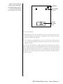
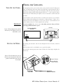
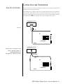
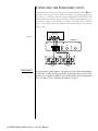
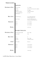
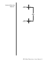
HTS-10
Home-Theater System
Owner’s Manual
®
CAUTION
RISK OF ELECTRIC SHOCK
DO NOT OPEN
WARNING: SHOCK HAZARD – DO NOT OPEN.
AVIS: RISQUE DE CHOC ELECTRIQUE – NE PAS OUVRIR.
CUIDADO: PELIGRO DE CHOQUE ELECTRICO – NO ABRIR.
CAUTION: TO REDUCE THE RISK OF ELECTRIC SHOCK
DO NOT REMOVE COVER (0R BACK)
NO USER SERVICEABLE PARTS INSIDE
REFER SERVICING TO QUALIFIED PERSONNEL
The lightning flash with arrowhead
symbol, within an equilateral triangle, is intended to alert the user to
the presence of uninsulated “dangerous voltage” within the product’s
enclosure that may be of sufficient
magnitude to constitute a risk of
electric shock to persons.
The exclamation point within
an equilateral triangle is intended
to alert the user to the presence
of important operating and maintenance (servicing) instructions in
the literature accompanying the
product.
THIS INFINITY PRODUCT IS DESIGNED FOR 120-VOLT USE ONLY! FOR DETAILED SAFETY PRECAUTIONS,
PLEASE SEE FOLLOWING PAGE IN THIS OWNER'S MANUAL FOR “IMPORTANT SAFETY INSTRUCTIONS.”
L’éclair avec le symbole de la flèche, placé dans les limites d’un triangel équilatéral est
prévu pour avertir l’utilisateur de la présence de “tension dangereuse” non isolée dans
l’enceinte du produit qui pourrait être d’une importance suffisante pour présenter un
risque d’électrocution aux personnes.
!
Le point d’exclamation dans un triangel équilateral est prévu pour avertir l’utilisateur
de la présence d’instructions importantes pour les opérations et l’entretien (service)
dans les manuels fournis avec l’appareil.
ATTENTION: POUR EVITER LES CHOCS ELECTRIQUES, INTRODUIRE LA LAME LA PLUS LARGE DE LA FICHE DANS LA BORNE
CORRESPONDANTE DE LA PRISE ET POUSSER JUSQUAU FOND.
Este destello luminoso con un símbolo de punta de flecha dentro de un triángulo equilátero tiene el objectivo de alertar al usuario sobre la presencia de “voltaje peligroso” no
aislado dentro de la caja del producto que puede ser de magnitud lo suficientemente
grande para constituir un riesgo de choque eléctrico para las personas.
!
Este punto de exclamación dentro de un triángulo equilátero tiene el objectivo de alertar al usuario sobre la existencia de instrucciones operativas y de mantenimiento (servicio) importantes en la literatura que acomaña el aparato.
CUIDADO: PARA REDUCIR EL RIESGO DE CHOQUE ELÉCTRICO, NO
RETIRE LA CUBIERTA (O RESPALDO). DENTRO NO HAY PIEZAS A
LAS QUE EL USUARIO PUEDA DAR SERVICIO. REMITA EL SERVICIO
AL PERSONAL DE SERVICIO CALIFICADO.
2 ◆ HTS-10 Home-Theater System – Owner’s Manual
IMPORTANT SAFETY INSTRUCTIONS
1) Read Instructions – All the safety and operating instructions should be read
before the product is operated.
2) Retain Instructions – The safety and operating instructions should be
retained for future reference.
3) Heed Warnings – All warnings on the product and in the operating instructions should be adhered to.
4) Follow Instructions – All operating and use instructions should be
followed.
5) Cleaning – Unplug this product from the wall outlet before cleaning. Do
not use liquid cleaners or aerosol cleaners. Use a damp cloth for cleaning.
Exception: A product that is meant for uninterrupted service and that for some
specific reason, such as the possibility of the loss of an authorization code for
a CATV Converter, is not intended to be unplugged by the user for cleaning
or any other purpose, may exclude the reference to unplugging the product in
the cleaning description otherwise required in number 5.
6) Attachments – Do not use attachments not recommended by the product
manufacturer as they may cause hazards.
7) Water and Moisture – Do not use this product near water – for example,
near a bathtub, washbowl, kitchen sink, or laundry tub; in a wet basement;
or near a swimming pool; and the like.
8) Accessories – Do not place this product on an
unstable cart, stand, tripod, bracket, or table. The
product may fall, causing serious injury to a
child or adult, and serious damage to the
product. Use only with a cart, stand, tripod,
bracket, or table recommended by the manufacturer, or sold with the product. Any
mounting of the product should follow the
manufacturer’s instructions, and should use a
mounting accessory recommended by the
manufacturer.
9) A product and cart combination should be
moved with care. Quick stop, excessive force, and
uneven surfaces may cause the product and cart combination to overturn.
10) Ventilation – Slots and openings in the cabinet are provided for ventilation and to ensure reliable operation of the product and to protect it from overheating, and these openings must not be blocked or covered. The openings
should never be blocked by placing the product on a bed, sofa, rug, or other
similar surface. This product should not be placed in a built-in installation
such as a bookcase or rack unless proper ventilation is provided or the manufacturer’s instructions have been adhered to.
11) Power Sources – This product should be operated only from the type of
power source indicated on the marking label. If you are not sure of the type of
power supply to your home, consult your product dealer or local power company. For products intended to operate from battery power, or other sources,
refer to the operating instructions.
12) Grounding or Polarization – This product may be equipped with a polarized alternating-current line plug (a plug having one blade wider than the
other). This plug will fit into the power outlet only one way. This is a safety
feature. If you are unable to insert the plug fully into the outlet, try reversing
the plug. If the plug should still fail to fit, contact your electrician to replace
your obsolete outlet. Do not defeat the safety purpose of the polarized plug.
13) Power-Cord Protection – Power-supply cords should be routed so that
they are not likely to be walked on or pinched by items placed upon or against
them, paying particular attention to cords at plugs, convenience receptacles,
and the point where they exit from the product.
14) Outdoor Antenna Grounding – If an outside antenna or cable system is
connected to the product, be sure the antenna or cable system is grounded so
as to provide some protection against voltage surges and built-up static charges.
Article 810 of the National Electrical Code, ANSI/NFPA 70, provides information with regard to proper grounding of the mast and supporting structure,
grounding of the lead-in wire to an antenna discharge unit, size for grounding
conductors, location of antenna-discharge unit, connection to grounding electrodes, and requirements for the grounding electrode. See Figure A.
Figure A
ANTENNA
LEAD-IN
WIRE
GROUND
CLAMP
ANTENNA
DISCHARGE UNIT
(NEC SECTION 810-21)
ELECTRIC
SERVICE
EQUIPMENT
GROUNDING CONDUCTORS
(NEC SECTION 810-21)
GROUND CLAMPS
POWER SERVICE GROUNDING
ELECTRODE SYSTEM
(NEC SECTION 810-21)
15) Lightning – For added protection for this product during a lightning
storm, or when it is left unattended and unused for long periods of time,
unplug it from the wall outlet and disconnect the antenna or cable system.
This will prevent damage to the product due to lightning and power-line
surges.
16) Power Lines – An outside antenna system should not be located in the
vicinity of overhead power lines or other electric light or power circuits, or
where it can fall into such power lines or circuits. When installing an outside
antenna system, extreme care should be taken to keep from touching such
power lines or circuits as contact with them might be fatal.
17) Overloading – Do not overload wall outlets, extension cords, or integral
convenience receptacles as this can result in a risk of fire or electric shock.
18) Object and Liquid Entry – Never push objects of any kind into this product through openings as they may touch dangerous voltage points or short-out
parts that could result in a fire or electric shock. Never spill liquid of any kind
on the product.
19) Servicing – Do not attempt to service this product yourself as opening or
removing covers may expose you to dangerous voltage or other hazards. Refer
all servicing to qualified service personnel.
20) Damage Requiring Service – Unplug this product from the wall outlet
and refer servicing to qualified service personnel under the following conditions:
a) When the power-supply cord or plug is damaged.
b) If liquid has been spilled, or objects have fallen into the product.
c) If the product has been exposed to rain or water.
d) If the product does not operate normally by following the operating instructions. Adjust only those controls that are covered by the operating instructions
as an improper adjustment of other controls may result in damage and will
often require extensive work by a qualified technician to restore the product to
its normal operation.
e) If the product has been dropped or damaged in any way.
f) When the product exhibits a distinct change in performance – this indicates
a need for service.
21) Replacement Parts – When replacement parts are required, be sure the
service technician has used replacement parts specified by the manufacturer or
that have the same characteristics as the original part. Unauthorized substitutions may result in fire, electric shock, or other hazards.
22) Safety Check – Upon completion of any service or repairs to this product,
ask the service technician to perform safety checks to determine that the product is in proper operating condition.
23) Wall or Ceiling Mounting – The product should be mounted to a wall or
ceiling only as recommended by the manufacturer.
24) Heat – The product should be situated away from heat sources such as
radiators, heat registers, stoves, or other products (including amplifiers) that
produce heat.
HTS-10 Home-Theater System – Owner’s Manual ◆ 3
INTRODUCTION
The Infinity HTS-10 is a compact, efficient universal satellite and subwoofer system that is ideal for
reproducing home-theater sound. With their versatile design, the satellite speakers can be placed
virtually anywhere on shelves or stands, or mounted on a wall or ceiling using the integral 4-way
mounting bracket. The bracket has crossholes for mounting and also acts as a door which hides the
mounting terminals. The powered subwoofer delivers tremendous bass performance from a compact, easy-to-place design.
ABOUT THIS MANUAL...
To start enjoying your new HTS-10 Home-Theater System, read and then follow all instructions
listed in this manual, as well as those found in the owner’s manuals of associated components in
your audio system. Save all instructions for future reference.
UNPACKING THE SPEAKERS
Carefully unpack the speakers. If you suspect damage from transit, report it
immediately to your dealer and/or delivery service. Keep the shipping cartons
and packing materials for future use. Open the package and verify the following contents:
PARTS LIST...
◆
(1) Powered subwoofer
◆
(5) Satellite speakers
◆
Speaker wire – 3 x 12'
2 x 40'
◆
Subwoofer cable – 15'
◆
Owner’s manual and warranty statement
◆
Hex wrench, 5⁄32" (4mm)
To prevent fire or shock hazard, DO NOT EXPOSE THIS SUBWOOFER SYSTEM TO RAIN OR
EXCESSIVE MOISTURE. To avoid electric shock, DO NOT OPEN THE SUBWOOFER! There are
no user-serviceable parts inside. Observe all warnings and cautions.
4 ◆ HTS-10 Home-Theater System – Owner’s Manual
PLANNING YOUR SYSTEM
The satellite speakers are used to reproduce sound for front and surround channels. Before deciding
where to best place your speakers, survey your room and study Figure 1.
TELEVISION
Figure 1. In this overhead view of
a typical installation, satellite speakers
are used to reproduce sound for the front,
center and surround channels. The
powered subwoofer provides extra bass
for effects and music.
SATELLITE SPEAKER
For Left Channel
SATELLITE
SPEAKER
On Top of Television
For Center Channel
POWERED
SUBWOOFER
SATELLITE SPEAKER
For Right Channel
SOFA
SATELLITE SPEAKER
For Left Surround
SATELLITE SPEAKER
For Right Surround
HTS-10 Home-Theater System – Owner’s Manual ◆ 5
PLACEMENT
NOTE: The satellite speakers can be placed directly on a shelf, or mounted on a wall using the
built-in bracket (see Figures 3 through 6).
FRONT CHANNELS...
For front left and right channels, place one speaker on the left and another on the right, along
either side of the television monitor.
CENTER CHANNEL...
For the center channel, place one speaker directly on top of, or below, your television, either
vertically or horizontally.
Since the speakers are magnetically shielded, you can place them very close to the TV without
worrying about the magnetic field distorting the TV picture.
SURROUND CHANNELS...
SUBWOOFER...
CAUTION: The metal plate on
the back of the subwoofer
acts as the heat sink for the
subwoofer’s internal amplifier.
Do not place pillows or
other objects against it.
For surround left and right channels, place one speaker on the left and another on the right, to
the side of, or behind the listening area.
Since installing a subwoofer can be somewhat more complicated than installing full-range
speakers, it is essential you read this section very carefully prior to connecting the subwoofer to
your system. Should you have questions relating to your installation, it is advisable to call either
your dealer or Infinity’s Customer Service Department for advice.
The performance of the subwoofer is directly related to its placement in the listening room and
how you align the subwoofer with its satellite speakers. Setting the volume of the subwoofer in
relationship to the left and right speakers is also of critical importance because it is essential that
the subwoofer integrates smoothly with the entire system. Setting the subwoofer’s volume level
too high will result in an overpowering, boomy bass. Setting the volume level too low will negate
the effect of the subwoofer.
We recommend placing the subwoofer at least 2 to 3 feet away from a television or a computer’s
disc-drive system to prevent smearing the colors of the TV picture or erasing the magnetic drive.
Here are several additional facts on installation that may prove useful. It is generally believed that
low frequencies (below 125Hz) are nondirectional and, therefore, placement of a subwoofer
within any listening room is not critical. While in theory it is true that the larger wavelengths of
extremely low frequencies are basically nondirectional, the fact is that when installing a
subwoofer within the limited confines of a room, reflections, standing waves and absorptions
generated within the room will strongly influence the performance of the subwoofer system. As
a result, specific location of the subwoofer becomes important, and we strongly recommend that
you experiment with placement before choosing a final location.
Placement will depend upon your room and the amount and quality of bass required (for
example, whether or not your room permits placement of the subwoofer near either satellite).
Never place the port too close to a wall or piece of furniture as this will prevent the port from
operating properly. Since the port is an integral part of the subwoofer’s design, it should always
be permitted free access to the listening room without obstruction to the pressure emerging from
it. Careful experimentation will enable you to determine the best position for the subwoofer (see
useful hints, next page).
6 ◆ HTS-10 Home-Theater System – Owner’s Manual
Figure 2. This view shows the
subwoofer positioned behind the
right-channel satellite speaker to
re-create the actual location of
bass instruments in an orchestra.
SUBWOOFER
RIGHT-CHANNEL
SATELLITE
PRIMARY
LISTENING
AREA
Here are some useful hints:
1. Experimentation with the port direction may be useful. At times directing the port away
from the listening area (to the side) may be advantageous because this may create a better
blend of bass within the listening room.
2. If bass response seems inadequate, move it closer to a wall or corner. If bass becomes too
heavy, try turning the subwoofer with the port facing away from the wall. This will tend to
diminish bass output.
It may take some time and patience to find the most pleasing acoustic location for your subwoofer. Testing for sonic balance and blending should always be made for your normal listening
position, using a wide range of source material. As a starting point, place the subwoofer behind
your right-channel satellite speaker, about 3 or 4 inches from the wall. We suggest trying this
location first because the bass instruments in an orchestra are usually located in the back and to
the right (see Figure 2).
HTS-10 Home-Theater System – Owner’s Manual ◆ 7
SHELF PLACEMENT OF THE SATELLITES
VERTICAL POSITION...
The satellite speakers can be positioned vertically in two positions on a shelf or stand, as shown
in Figure 3. Set each satellite flat, with the logo at the bottom and the bracket facing inward.
You can also push the speakers gently back for a 20° tilt.
VERTICAL PLACEMENT ON A SHELF
Figure 3. This illustration shows how to
vertically position the speakers
two ways.
HORIZONTAL POSITION...
(side view)
(side view)
Flat
Position
20° Tilt-Up
Position
The satellite speakers can also be positioned horizontally in three positions on a shelf, as shown
in Figure 4. Set each speaker flat, or push the speakers gently back for a 20° tilt. Rotate the logo
to match the orientation of the speaker. To provide a 10° tilt-down angle, loosen the
bracket screw on the rear door with the hex wrench (included) and adjust the bracket to Bracket
Open, Position #1. Tighten the bracket screw when you have reached the desired angle.
NOTE: You may want to route the wires before tightening the bracket screw (see Figure 8 on page 11).
HORIZONTAL PLACEMENT ON A SHELF
Figure 4. This illustration shows how to
horizontally position the speakers
three ways.
(rear view)
Screw
❶ Loosen Screw
❷ Rotate Bracket
❸ Tighten Screw
Bracket
Positions
(side view)
Flat Position
(Bracket Closed)
8 ◆ HTS-10 Home-Theater System – Owner’s Manual
20° Tilt Up
(Bracket Closed)
10° Tilt Down
(Bracket Open,
Position #1)
NOTE: The customer is responsible for
the correct selection and use of mounting
hardware (available through hardware
stores) that will ensure the proper and
safe wall-mounting of the speakers.
WALL-MOUNTING THE SATELLITES
The satellite speakers can be wall- or ceiling-mounted, as shown in Figures 5 and 6. You can
mount the speakers with #6 wood screws (not included), using the built-in mounting bracket.
Use the enclosed template to mark the desired position of each speaker on a wall or ceiling.
Locate a stud for secure mounting and use heavy-duty wood screws with long threads. Test
the mounting thoroughly before installation.
VERTICAL MOUNTING...
To mount the speaker vertically on a wall, fasten the wood screws (not included) to a
wall stud, leaving a 3⁄16" clearance between the base of the screw head and the wall. If desired,
loosen the bracket screw, adjust the bracket angle, and tighten the bracket screw.
NOTE: You may want to route the wires before tightening the bracket screw (see Figure 8 on page 11).
Then orient the speaker vertically, align the crossholes on the rear of the speaker with the wood
screws, and slide the speaker down.
VERTICAL MOUNTING USING BRACKET
Figure 5. This illustration shows how to
mount the speaker vertically on a wall or
ceiling four different ways.
(rear view)
❶ Loosen Screw
❷ Rotate Bracket
❸ Tighten Screw
wall
wood
screw
(side view)
Screw
(inside hole)
Positions
3/16"
Slide Speaker Down
Onto Wood Screws
#6 Wood Screws
(fasten to wall stud)
(top view)
20° From Wall
(Bracket Closed)
45° From Wall
(Bracket Open,
Position #1)
67.5° From Wall
(Bracket Open,
Position #2)
90° From Wall
(Bracket Open,
Position #3)
HTS-10 Home-Theater System – Owner’s Manual ◆ 9
HORIZONTAL MOUNTING...
For horizontal mounting, fasten the #6 wood screws (not included) to a wall stud, leaving a 3⁄16"
clearance between the base of the screw head and the wall. If desired, loosen the bracket screw,
adjust the bracket angle, and tighten the bracket screw.
NOTE: You may want to route the wires before tightening the bracket screw (see Figure 8 on page 11).
Then orient the speaker horizontally, align the crossholes on the rear of the speaker with the
screws, and slide the speaker down. Rotate the logo to match the orientation of the speaker.
Figure 6. This illustration shows how to
mount the speaker horizontally on a
wall or ceiling four different ways.
HORIZONTAL MOUNTING USING BRACKET
(rear view)
3/16"
wall
wood
screw
#6 Wood Screws
(fasten to wall stud)
Screw
(inside hole)
(side view)
❶ Loosen Screw
❷ Rotate Bracket
❸ Tighten Screw
Slide Speaker Down
Onto Wood Screws
Positions
(side view)
20° Tilt Up
(Bracket Closed)
10 ◆ HTS-10 Home-Theater System – Owner’s Manual
45° Tilt Up
(Bracket Open,
Position #1)
67.5° Tilt Up
(Bracket Open,
Position #2)
90° Tilt Up
(Bracket Open,
Position #3)
WIRING THE SATELLITES
TURN OFF ALL POWER...
After placing the speakers, you are ready to connect your system. First turn off all audio system
power. Use high-quality speaker wire to make your connections. If you need more wire than is
provided, use at least #16 gauge speaker wire with polarity coding. The side of the wire with a
ridge or other coding is usually considered positive polarity (i.e., + ). Also, consult the owner’s
manuals that were included with your amplifier, receiver, or television to confirm connection
procedures.
On the back of the satellite, loosen the bracket screw and rotate the bracket to access terminals.
Observe polarities when making speaker connections, as shown in Figure 7. Connect each +
terminal on the back of the amplifier or receiver to the respective + (red) terminal on each
speaker. Similarly, connect the – (black) terminals in the same way.
IMPORTANT!
Do not reverse polarities (i.e., + to – or – to +) when making connections. Doing so will cause
poor imaging and diminished bass response.
(rear view)
Receiver or Amplifier
Figure 7. Wiring diagram shows polarity
connections for one channel of a stereo or
home-theater system.
(rear view)
Output
+
–
+
One Channel Shown
ROUTING THE WIRES...
–
red terminal = +
black terminal = –
Bracket Not Shown
After making your connections, route the wires through either hole in the door, as shown in
Figure 8.
NOTE: You may need to loosen the bracket screw to open the door further.
After you finish connecting your system, return the door to the desired angle and tighten the
bracket screw.
Figure 8. This illustration shows how to
route the wires through either hole in the
speaker’s bracket and connect them to
the terminals.
blk
red
(rear view)
–
Route Speaker
Wire Through
Either Hole
+
❶ Loosen Terminal
❷ Insert Bare End;
Tighten Terminal
Output From
Amplifier or Receiver
HTS-10 Home-Theater System – Owner’s Manual ◆ 11
WIRING THE SUBWOOFER
IDENTIFYING CONTROLS AND
CONNECTING AC POWER
CONTROLS...
Refer to Figure 9 to identify the controls of your subwoofer’s internal amplifier:
❶ High-Level Input and Output terminals
❷ Low-Level Input jacks: connect to preamplifier outputs
❸ Crossover Frequency: controls upper-corner roll-off point
❹ Power-On Indicator
❺ Volume Control: controls volume of subwoofer
BEFORE CONNECTING
YOUR SUBWOOFER...
Turn off your entire audio system prior to connecting your subwoofer.
Connect your subwoofer to an unswitched AC wall outlet.
Figure 9.
+ L –
– R +
Low-Level In
SPKR
In
Crossover
Frequency
Power
Volume
L
SPKR
Out
R
50
❷
❶
Digital Technology
120V
60Hz
160W
12 ◆ HTS-10 Home-Theater System – Owner’s Manual
CAUTION
®
RISK OF ELECTRIC SHOCK
DO NOT OPEN
WARNING: SHOCK HAZARD – DO NOT OPEN.
AVIS: RISQUE DE CHOC ELECTRIQUE – NE PAS OUVRIR.
CUIDADO: PELIGRO DE CHOQUE ELECTRICO – NO ABRIR.
150
❸
Min
❹
Max
❺
CONNECTING THE SUBWOOFER
TURN OFF ALL POWER...
There are several ways to connect your subwoofer. Read this section carefully to determine which
method is best suited for your installation.
The subwoofer may be fed directly with a low-level signal taken from your receiver’s subwooferoutput to connect your subwoofer. Connect one end of each stereo pair of leads to your receiver/
processor’s left and right outputs and connect the other end to the corresponding left and right
LOW-LEVEL INPUTS ❷ on the subwoofer. This cable is included with the system.
SUBWOOFER OUTPUT
L
R
Figure 10.
LEFT
+ L –
– R +
SPKR
In
Low-Level In
L
SPKR
Out
R
SUBWOOFER
RIGHT
SUBWOOFER OUTPUT
NOTE: If your receiver/processor has
only one subwoofer output, it is
recommended that you use
the supplied “Y”-connector as shown.
Y-Connector
LEFT
+ L –
SPKR
In
SPKR
Out
– R +
Low-Level In
L
R
SUBWOOFER
RIGHT
HTS-10 Home-Theater System – Owner’s Manual ◆ 13
CONNECTING THE SUBWOOFER (CONT.)
The subwoofer may be connected to your system using the HIGH-LEVEL INPUTS ❶ on the
plate located on the rear panel of the subwoofer. Use speaker wire, maintaining proper polarity
(+ to + and – to –). Attach the speaker wire to the left and right HIGH-LEVEL INPUTS on the
subwoofer and the other ends to the proper left and right OUTPUTS on your amplifier or receiver.
Then connect the outputs of the subwoofer to the front left and right satellites as shown in
Figure 11. The additional speaker wires required for this connection method are not included
with the system.
AMPLIFIER
OUTPUTS
LEFT
+
Figure 11.
RIGHT
–
+
–
SUBWOOFER
+
L
–
–
R
+
Low-Level In
SPKR
In
Crossover
Frequency
Power
Volume
L
Phase
SPKR
Out
R
50
+
–
L. SATELLITE
Rear View
IMPORTANT!
150
+
Min
Max
–
R. SATELLITE
Rear View
The subwoofer has a variable frequency control that can be used to block unwanted frequencies (between 50 – 150Hz) from being reproduced by the subwoofer. Where you set this control
depends on the low-frequency capabilities of your satellite speakers and the configuration of
your system. Refer to Step 6 of “Operating the Subwoofer” on page 16.
14 ◆ HTS-10 Home-Theater System – Owner’s Manual
A FEW SUGGESTIONS
We recommend that you not operate your speakers or subwoofer with the bass, treble and loudness controls set to full boost. This will place undue strain on your electronics and speakers and
could damage them.
The volume control setting on your receiver/processor is not a specific indication of the overall
loudness level of the speakers. The only important consideration is the loudness level at which
the system can be played regardless of where the volume control is set.
Always turn down the volume control setting on your receiver/processor when changing a cassette or CD, or switching inputs to AM or FM operation. Excessively loud transients (clicks or
popping sounds) can damage the satellite speakers and possibly the subwoofer.
IMPORTANT!
Whenever changing cables, pulling plugs, etc., ALWAYS TURN OFF ALL EQUIPMENT, including the subwoofer. This prevents transients from entering the speakers and prevents electrical
energy from reaching you. Keep all connections out of the reach of children.
OPERATING THE SYSTEM
CHECKING PLAYBACK...
Check the speakers for playback by first setting the audio system volume control for a
minimum level, and then applying power to your system. Play a favorite music or video
segment and increase the volume control to a comfortable level.
NOTE: You should hear balanced audio reproduction across the entire frequency spectrum. If not, check all
wiring connections and see In Case of Trouble for more help.
SURROUND MODES...
When using the HTS-10 System in a Dolby* Pro Logic* home-theater system, make sure the receiver’s center-channel mode is set to “Normal”. When using the HTS-10 System in a Dolby Digital or
DTS® home-theater system, make sure the receiver’s speaker modes are set to “Small”.
HTS-10 Home-Theater System – Owner’s Manual ◆ 15
OPERATING THE SUBWOOFER
SET CONTROLS...
1. Initially set the subwoofer’s Volume control ❺ (Fig. 9) to the minimum position.
2. Initially set the subwoofer’s Crossover Frequency control ❸ (Fig. 9) to 12 o’clock position.
POWER ON...
3. Turn on your entire audio system and play any music source.
4. Turn the Volume control ❺ (Fig. 9) to its mid-position. If no sound emanates from the subwoofer, check the AC line cord and input cables. Are the connectors on the cables making
proper contact? Is the AC plug connected to a “live” receptacle?
ADJUST VOLUME...
5. Set the overall volume control of the receiver/processor to a comfortable level. Adjust the
subwoofer’s Volume control ❺ (Fig. 9) until you obtain a pleasing blend of bass. Bass
response should not overpower the room but rather be adjusted so there is a harmonious
blend across the entire musical range. Many users have a tendency to set the subwoofer volume too loud, following the belief that a subwoofer is there to produce lots of bass. This is
not entirely true. A subwoofer is there to enhance bass, extending the response of the entire
system so the bass can be felt as well as heard. However, overall balance must be maintained;
otherwise, the music will not sound natural. An experienced listener will set the volume of
the subwoofer so its impact on bass response is always there but is never obtrusive.
CROSSOVER FREQUENCY
CONTROL...
6. The Crossover Frequency control ❸ (Fig. 9) sets the high-frequency roll-off, and is
adjustable from 50 to 150Hz. Where you set this control depends on the low-frequency
capabilities of your satellite speakers, system placement, and other factors affecting the midbass region.
a. When using the HTS-10 System in a Dolby Digital or DTS home-theater system
with a dedicated LFE (Low Frequency Effects) output, set this control knob to 150Hz
(full clockwise position). Set your receiver/processor speaker mode to “small” or
“high-pass” for all channels. Some receiver/processors allow you to adjust the high-pass
frequency for the “small” or “high-pass” setting. If your receiver/processor has this
capability, it is recommended that you set the high-pass frequency to the lowest
setting that is 80Hz or above. Consult the manual for your receiver/processor for more
information about these adjustments.
b. When using the HTS-10 in a Dolby Pro Logic home-theater or any standard system without
a dedicated LFE (Low Frequency Effects) output, the recommended crossover
frequency is 80Hz. Set the control knob to approximately the 12 o’clock position.
ROOM PLACEMENT...
7. Room placement of the subwoofer is also an important aspect of its installation. It may be
necessary for you to try various locations in your listening room before you choose the final
location. Some possible starting points include: behind the right-channel satellite speaker,
along the back wall between the satellites, along a side wall, or behind a couch or a chair.
In general, the closer the subwoofer is to walls and corners, the greater the effect of lowfrequency enhancement. Experiment with the Volume control and different room locations
until you are pleased with the result you obtain for your particular application.
16 ◆ HTS-10 Home-Theater System – Owner’s Manual
A WORD OF ADVICE
The Low-Frequency Roll-off and Volume controls may be set anywhere within their rotation.
However, it will be a most unusual circumstance if you have to set the Volume control
completely clockwise. This may indicate an unbalanced condition in your system (too much
bass) or an especially large room, or room placement may not be correct. Try several other locations before concluding that the Volume control must be set at maximum.
CARE OF YOUR SPEAKER SYSTEM
The satellites and powered subwoofer enclosures do not require any routine maintenance. When
needed, use a soft cloth, dampened with water only, to remove any fingerprints or to wipe off
dust. Clean the grille by gentle vacuuming or with a damp cloth.
NOTE: Do not use any cleaning products or polishes on the enclosure or grille.
IN CASE OF TROUBLE
Before consulting your dealer, try these simple troubleshooting steps:
• If the sound quality is distorted, listen to each speaker separately.
• If distortion is present in both, the problem is probably somewhere else in your system.
• If only one channel is distorted, switch the left and right speaker leads at the receiver.
• If the distortion moves to the other speaker, the problem is not in the speaker.
• If you need further assistance, contact your local Infinity retail dealer.
HTS-10 Home-Theater System – Owner’s Manual ◆ 17
SPECIFICATIONS
SATELLITES
PERFORMANCE DATA...
DRIVE UNITS...
DIMENSIONS...
Frequency Range:
70 ~ 20,000Hz
Sensitivity:
86dB spl @ 1m/2.83 V (anechoic conditions)
Impedance:
8 Ω nominal
Maximum Peak Output:
104dB (spl on program)
Recommended Maximum
Amplifier Power:
10 ~ 100W
Low/Mid Frequency:
One 4" (100mm) magnetically
shielded, polypropylene cone
High Frequency:
One 1⁄2" (12.5mm) magnetically
shielded, polycarbonate dome tweeter
Width:
4-1⁄2" (114mm)
Height:
8-1⁄2" (216mm)
Depth:
5-1⁄2" (140mm)
WEIGHT...
3.4 lb/1.6 kg
POWERED SUBWOOFER
PERFORMANCE DATA...
DRIVE UNITS...
FINISH...
DIMENSIONS...
Frequency Response (±3dB):
45Hz ~ 150Hz
Output (RMS):
75W
Driver:
8"
Crossover
Frequency:
50Hz ~ 150Hz
(continuously variable)
Cabinet Finish:
Ebony Pica
Height:
13-1/4" (337mm)
Width:
11-1/2" (292mm)
Depth:
11-1/2" (292mm)
WEIGHT...
18 ◆ HTS-10 Home-Theater System – Owner’s Manual
26 lbs/11.8 kg
SATELLITE MOUNTING
TEMPLATE...
Bracket
Crosshole
2.52"
(64mm)
Bracket
Crosshole
HTS-10 Home-Theater System – Owner’s Manual ◆ 19
Infinity continually strives to update and improve existing products, as well as create new ones.
The specifications and construction details in this and related Infinity publications are therefore
subject to change without notice.
©2001 Infinity Systems, Inc., 250 Crossways Park Drive, Woodbury, NY 11797 USA
(800) 553-3332
www.infinitysystems.com
Infinity is a registered trademark of Infinity Systems, Inc.
*Trademarks of Dolby Laboratories.
DTS is a trademark of Digital Theater Systems, Inc.
P/N:HTS10OM5/01