1
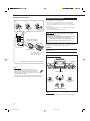
AUDIO/VIDEO CONTROL RECEIVER
RX-DP10VBK
LEARN TRANSMIT
STANDBY
MAIN ROOM SUB ROOM
MAIN ROOM SUB ROOM
ON/OFF
ON
TV/CATV/DBS
VCR 1
STANDBY/ON
STANDBY/ON
ON/OFF
MAIN ROOM SUB ROOM LEARN
DVD MULTI
PHONO
CD
VCR 1
VCR 2
TAPE/MD
CDR
TV/DBS
DVD
VIDEO
FM
1
2
AM
ANALOG/DIGITAL
EFFECT
INPUT
3
ROOM SIZE
SOUND
4
5
6
LIVENESS
7/P
8
10
0
RETURN
FM MODE
9
WALL
TEST
+10
MASTER VOLUME
100+
SURROUND
DSP
THX
ON/OFF
MODE
ON/OFF
STANDBY
SLEEP
DIMMER
TV
CATV/
DBS
/ REW
PLAY
DOWN
TUNING
REC
STOP
DIMMER
CC CONVERTER
CC CONVERTER
LINE DIRECT
STANDBY/ON
MAIN ROOM
ON/OFF
DOOR
UP
FF/
RX-DP10V
UP
PAUSE
SUB ROOM
ON/OFF
DOOR
DOWN
TV/VIDEO
TV VOL CHANNEL
VOLUME
MUTING
AUDIO/VIDEO CONTROL RECEIVER
SETUP
MENU
ADJUST
MENU
D I G I T A L
TEXT
DISPLAY
SET
DVD
MENU
SURROUND
D I G I T A L
EXIT
LIGHT
PHONES
S-VIDEO
VIDEO
L—AUDIO—R
VIDEO
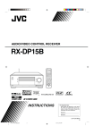
RM-SRXDP10J REMOTE CONTROL
A/V CONTROL RECEIVER
INSTRUCTIONS
For Customer Use:
Enter below the Model No. and Serial
No. which are located either on the rear,
bottom or side of the cabinet. Retain this
information for future reference.
Model No.
Serial No.
LVT0722-003A
[J]
RX-DP10VBK[J]cover_f
1
01.6.18, 7:02 PM
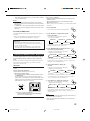
Warnings, Cautions and Others
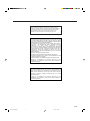
CAUTION
RISK OF ELECTRIC SHOCK
DO NOT OPEN
CAUTION:
TO REDUCE THE RISK OF ELECTRIC SHOCK.
DO NOT REMOVE COVER (OR BACK)
NO USER SERVICEABLE PARTS INSIDE.
REFER SERVICING TO QUALIFIED SERVICE PERSONNEL.
The lightning flash with arrowhead symbol,
within an equilateral triangle is intended to
alert the user to the presence of uninsulated
"dangerous voltage" within the product's
enclosure that may be of sufficient
magnitude to constitute a risk of electric
shock to persons.
The exclamation point within an equilateral
triangle is intended to alert the user to the
presence of important operating and
maintenance (servicing) instructions in the
literature accompanying the appliance.
WARNING: TO REDUCE THE RISK OF FIRE
OR ELECTRIC SHOCK, DO NOT EXPOSE
THIS APPLIANCE TO RAIN OR MOISTURE.
CAUTION
To reduce the risk of electrical shocks, fire, etc.:
1. Do not remove screws, covers or cabinet.
2. Do not expose this appliance to rain or moisture.
Caution ––
(STANDBY/ON) switch!
Disconnect the mains plug to shut the power off completely. The
(STANDBY/ON) switch in any position does not disconnect the mains line. The power can be remote controlled.
Caution––SPEAKER LOAD SELECTOR switch!
Match the position of SPEAKER LOAD SELECTOR switch on the
back panel to the impedance of the speaker connected, to protect
from overheating.
22.0 kg / 49.0 lb.
CAUTION!
To avoid personal injury or accidentally
dropping the unit, have two persons unpack,
carry, and install the unit.
G-1
RX-DP10VBK[J]safety_f
1
01.6.18, 7:02 PM
Note to CATV system installer:
This reminder is provided to call the CATV system installer’s
attention to Section 820-40 of the NEC which provides guidelines
for proper grounding and, in particular, specifies that the cable
ground shall be connected to the grounding system of the
building, as close to the point of cable entry as practical.
For the main unit:
This equipment has been tested and found to comply with the limits
for a Class B digital device, pursuant to part 15 of the FCC Rules.
These limits are designed to provide reasonable protection against
harmful interference in a residential installation.
This equipment generates, uses and can radiate radio frequency
energy and, if not installed and used in accordance with the
instructions, may cause harmful interference to radio
communications. However, there is no guarantee that interference
will not occur in a particular installation. If this equipment does cause
harmful interference to radio or television reception, which can be
determined by turning the equipment off and on, the user is
encouraged to try to correct the interference by one or more of the
following measures:
Reorient or relocate the receiving antenna.
Increase the separation between the equipment and receiver.
Connect the equipment into an outlet on a circuit different from that
to which the receiver is connected.
Consult the dealer or an experienced radio/TV technician for help.
Changes or modifications not expressly approved by the
manufacturer for compliance could void the user’s authority to
operate the equipment.
For the remote control:
This device complies with Part 15 of the FCC Rules. Operation is
subject to the following two conditions: (1) This device may not
cause harmful interference, and (2) this device must accept any
interference received, including interference that may cause
undesired operation.
Changes or modifications not expressly approved by the
manufacturer for compliance could void the user’s authority to
operate the equipment.
G-2
RX-DP10VBK[J]safety_f
2
01.6.18, 7:02 PM
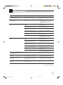
Table of Contents
Introduction ................................................ 2
Features ...................................................................................... 2
Precautions ................................................................................. 2
Parts Identification ...................................... 3
Getting Started ........................................... 6
Before Installation ...................................................................... 6
Checking the Supplied Accessories ........................................... 6
Connecting the FM and AM Antennas ....................................... 6
Connecting the Speakers ............................................................ 7
Connecting Audio/Video Components ....................................... 9
7 Analog Connections ............................................................... 9
7 Digital Connections .............................................................. 14
Setting Up the RF Rod Antenna ............................................... 15
Setting Up the IR Signal Transmitter ....................................... 15
Connecting the Power Cord ..................................................... 16
Putting Batteries in the Remote Control .................................. 16
Multi-Room Operations ............................... 17
Required Connections for Sub-Room ...................................... 17
Basic Operating Procedure for Main Room ............................. 18
Basic Operating Procedure for Sub-Room ............................... 19
Main Room Operations ............................... 20
Turning the Power On and Off (Standby) ................................ 20
Canceling the Main Room Operations ..................................... 21
Selecting the Main Room Source to Play ................................ 21
Adjusting the Main Room Volume ........................................... 22
Activating the Main Room Front Speakers .............................. 23
Selecting the Analog or Digital Input Mode ............................ 23
Attenuating the Input Signal .................................................... 24
Muting the Main Room Sound ................................................. 24
Changing the Display Brightness ............................................. 25
Turning Line Direct On and Off ............................................... 25
Making Sounds Natural ............................................................ 25
Changing the Source Name ...................................................... 25
Using the Sleep Timer .............................................................. 26
Sub-Room Operations ................................. 27
Turning the Power On and Off (Standby) and Selecting
the Sub-Room Operations .................................................. 27
Canceling the Sub-Room Operations ....................................... 28
Selecting the Sub-Room Source to Play .................................. 29
Adjusting the Sub-Room Volume ............................................. 29
Activating the Sub-Room Front Speakers ................................ 30
Muting the Sub-Room Sound ................................................... 30
Receiving Radio Broadcasts ........................ 31
Tuning into Stations Manually ................................................. 31
Using Preset Tuning ................................................................. 32
Selecting the FM Reception Mode ........................................... 32
7 Setting the Surround Sound Output—SURROUND
SPEAKER ............................................................................ 38
7 Setting the Digital Input Terminals—DIGITAL IN ............. 38
7 Preparing for the Component Video Input
—COMPONENT IN ............................................................ 39
7 Turning On and Off the Video Output—VIDEO POWER ... 39
7 Preparing for the Sub-Room Operations—SUB ROOM ...... 40
7 Showing the Text Information on the Display
—FL DISPLAY .................................................................... 40
7 Memorizing the Volume Level for Each Source
—ONE TOUCH OPE(ration) ............................................... 40
Sound Adjustments .................................... 41
Adjustment Menu Configuration ............................................. 41
Operation through On-Screen Display Menus ......................... 42
Menu Operating Procedure ...................................................... 43
7 Adjusting the Speaker Channel Output Levels—LEVEL .... 44
7 Adjusting the Parametric Equalizer—PARAMETRIC EQ ..... 44
7 Adjusting the DSP Parameters—DSP PARAMETER ......... 45
7 Adjusting the Center Channel—CENTER CHANNEL ......... 45
Using the Surround Modes ................................ 46
Reproducing Theater Ambience ............................................... 46
Introducing the Surround Modes ............................................. 46
Activating the Surround Modes ............................................... 48
Adjusting the Surround Sounds Temporarily ........................... 49
Using the DSP Modes ....................................... 50
Reproducing the Sound Field ................................................... 50
Introducing the DSP Modes ..................................................... 50
Activating the DSP Modes ....................................................... 51
Adjusting the DSP Parameters Temporarily ............................ 52
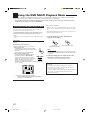
Using the DVD MULTI Playback Mode .......... 53
Activating the DVD MULTI Playback Mode .......................... 53
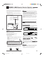
COMPU LINK Remote Control System ......... 54
TEXT COMPU LINK Remote Control System .. 56
7 Showing the Disc Information on the TV Screen
(Either in the Main Room or in the Sub-Room) ................... 57
7 Searching for a Disc (Only for the CD player) ..................... 58
7 Entering the Disc Information .............................................. 59
AV COMPU LINK Remote Control System .... 61
Operating JVC’s Audio/Video Components ... 64
Operating Audio Components .................................................. 64
Operating Video Components .................................................. 66
Operating Other Manufacturers’ Equipment ... 67
Changing the Preset Signal Codes ........................................... 67
Storing the Remote Signals Manually ...................................... 71
Basic Settings ........................................... 33
Troubleshooting ......................................... 74
Setup Menu Configuration ....................................................... 33
Operation through On-Screen Display Menus ......................... 34
Menu Operating Procedure ...................................................... 35
7 Setting the Speakers—SPEAKER SETTING ...................... 36
7 Setting the Speaker Distance—SPEAKER DISTANCE ...... 36
7 Setting the Bass Sounds—SUBWOOFER ........................... 37
7 Setting the Dynamic Range—DYNAMIC RANGE .............. 38
7 Preparing for THX Surround Modes—THX .......................... 38
Specifications ............................................ 76
Indicates the functions YOU CAN ALSO USE when
the receiver is ready for the sub-room operations.
1
EN01-16_RX-DP10VBK[J]_f
1
01.6.19, 0:25 PM
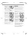
Introduction
We would like to thank you for purchasing one of our JVC products.
Before operating this unit, read this manual carefully and thoroughly to obtain the best possible performance
from your unit, and retain this manual for future reference.
Features
Precautions
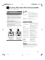
THX Surround EX (DTS-ES compatible)
THX Surround EX is a format that has additional left and right
surround back channels on the basis of Dolby Digital 5.1
channels. It improves the definition and the sense of sound
movement in surround (rear) channels.
• This receiver is also compatible with DTS Extended Surround
(DTS-ES)—another multichannel surround containing
additional left and right surround back channels.
7.1 channel DAP (Digital Acoustic Processor)
Sound field simulation technology allows precise ambience
recreation of existing theaters and halls. Thanks to the highperformance DSP (Digital Signal Processor) and high-capacity
memory, you can enjoy 7.1-channel surround by playing 2channel or multichannel software.
Multichannel headphone virtual surround
sound—3D HEADPHONE
The built-in headphone virtual surround system is compatible with
multichannel software like Dolby Digital, DTS Surround, etc.
Thanks to the new signal processing algorithms used by the highperformance DSP, you can enjoy a natural surround sound through
the headphones.
192 kHz/24 bit PEM DD audio DA converter
The JVC-exclusive converter is now upgraded to be fully
compatible with DVD Audio’s high specifications. Subtle nuances
are accurately reproduced.
CC (Compensative Compression) converter
CC Converter eliminates jitter and ripples, achieving a drastic
reduction in digital distortion by processing the digital music data
in 24 bit–quantization and by expanding the sampling frequency
to 176.4 kHz (for fs 44.1 kHz signals)/192 kHz (for fs 48 kHz
signals). By using the CC Converter, you can obtain a natural
sound field from any source.
Multi-room operations
You can connect two pairs of front speakers to the
RX-DP10VBK, and use them to listen to different sources in the
different rooms (Main room and Sub-room) at the same time.
RF/IR multi-brand/learning remote control
The remote control sends out not only IR (infrared) signals but
also RF (radio frequency) signals as coded commands to control
the receiver. The RF rod antenna can receive the RF signals sent
from the remote control to operate the receiver. In addition, the
supplied IR signal transmitter can transmit IR signals which can
control other video components.
• The remote control provided for this receiver can transmit
control signals for many manufacturers’ components, and can
learn and store any signals.
COMPU LINK/TEXT COMPU LINK/AV COMPU
LINK remote control systems
These COMPU LINK remote control systems allow you to
operate other JVC audio/video components from this receiver.
Power sources
• When unplugging the receiver from the wall outlet, always pull
the plug, not the AC power cord.
• Do not handle the AC power cord with wet hands.
• If you are not going to operate the receiver for an extended period
of time, unplug the AC power cord from the wall outlet.
Multi-room operations
• Do not use the remote control outdoors or install the speakers
outdoors.
• When operating the receiver from the place where you cannot see
the receiver (for example, when controlling the receiver installed
in the living room from the kitchen), pay attention to the following
not to surprise other people:
– Be careful not to turn up the volume so high when controlling
the receiver without listening to the playback sound.
– Be careful not to surprise other people with a sudden sound
coming out of the receiver when turning it on. (A sudden stop of
the sound may also surprise other people.)
• If the receiver operates by itself or malfunctions, the following
causes will be considered:
– Interference to RF communication between the receiver and the
remote control from outside.
– The remote control is operated unintentionally. For example, a
book is placed on the remote control, possibly, depressing some
buttons on the remote control.
• If your neighbour uses the same or similar RF remote control
system, the receiver may happen to receive the RF signals sent
from such an RF remote control system, which could cause your
receiver to be operated unintentionally. If this happens, set the
BAND selectors both on the rear and on the remote control to
another band (either BAND 1 or BAND 2)—see page 15 for
details.
If the problem still persists, stop using the RF rod antenna and the
remote control, and consult your JVC dealer or the nearest JVC
Service Center.
Ventilation
Seven high power amplifiers built in this receiver will generate heat
inside the cabinet. When the temperature inside the cabinet
increases, the internal fan automatically starts rotating to reduce the
internal temperature. For safety, observe the following carefully.
• Make sure there is good ventilation around the receiver. Poor
ventilation could overheat and damage the receiver.
• Do not block the ventilation openings or holes. (If the ventilation
openings or holes are blocked by a newspaper or cloth, etc., the
heat may not be able to get out.)
Others
• Should any metallic object or liquid fall onto the unit, unplug the
unit and consult your dealer before operating any further.
• Do not use this receiver in a bathroom or places with water.
• Do not place any containers filled with water or liquids (such as
cosmetics or medicines, flower vases, potted plants, cups, etc.) on
top of this receiver.
• Do not disassemble the unit since there are no user serviceable
parts inside.
If anything goes wrong, unplug the AC power cord and consult your
JVC dealer.
2
EN01-16_RX-DP10VBK[J]_f
2
01.6.19, 0:25 PM
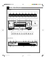
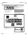
Parts Identification
Front Panel
1
2
3
4
5
6
7
8
9
SPEAKERS 1
INPUT MODE
/ INPUT ATT
SURROUND
ON / OFF
DSP MODE
SOUND
SELECTOR
ADJUST MENU
DOWN
UP
SET
SPEAKERS 2
/ SUB ROOM
SUB ROOM
CONTROL
THX
ON / OFF
LINE DIRECT
FM MODE
SETUP MENU
LEFT
RIGHT
EXIT
w
e
r
y
u
i
p
q
o
;
t
s
a
d f
g
h
DOOR
DOWN
MASTER VOLUME
STANDBY
DIMMER
CC CONVERTER
STANDBY/ON
MAIN ROOM
ON/OFF
DOOR UP
RX-DP10V
SUB ROOM
ON/OFF
DOOR DOWN
SPEAKERS 1
INPUT MODE
/ INPUT ATT
SURROUND
ON / OFF
DSP MODE
SOUND
SELECTOR
ADJUST MENU
DOWN
UP
SET
SPEAKER 2
/ SUB ROOM
SUB ROOM
CONTROL
THX
ON / OFF
LINE DIRECT
FM MODE
SETUP MENU
LEFT
RIGHT
EXIT
To open the front door,
press DOOR DOWN.
(For more details, see
page 18.)
D I G I T A L
SURROUND
D I G I T A L
PHONES
AUDIO/VIDEO CONTROL RECEIVER
S-VIDEO
VIDEO
L—AUDIO—R
VIDEO
k
j
x
z
l
/
DVD
DVD MULTI
VCR 1
VCR 2
TV/DBS
VIDEO
CD
PHONO
TAPE/MD
CDR
FM
AM
Display Window
1
2
DIGITAL AUTO
ANALOG
L
C
R
SUBWFR
LFE
LS
RS
S
SB
LINEAR PCM
DIGITAL
4
5
TUNED
STEREO
6
7
AUTO MUTING
PROLOGIC
DSP
SLEEP
ONE TOUCH OPERATION
SPEAKERS
1 2 SUB ROOM
MIDNIGHT MODE
PARAMETRIC EQ
VOLUME
INPUT ATT
HEADPHONE
~
dB
!
@
3
EN01-16_RX-DP10VBK[J]_f
90
8
3D-PHONIC
SB
=
3
3
01.6.19, 0:25 PM
#
-
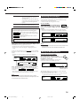
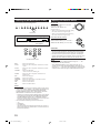
Refer to the pages in parentheses for details.
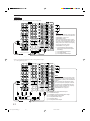
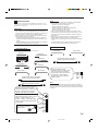
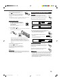
Front Panel
Display Window
1
2
3
4
5
6
7
8
9
p
q
w
e
r
t
y
u
i
o
1 ANALOG indicator (24)
• Lights up when an analog input (source) is selected.
2 DIGITAL AUTO indicator (24)
• Lights up when auto digital input (DIGITAL AUTO) is
selected.
3 Surround/DSP mode indicators
• Indicate the current Surround/DSP mode setting.
4 TUNED indicator (31)
• Lights up when a station is received.
5 STEREO indicator (31)
• Lights up when an FM stereo station is received.
6 AUTO MUTING indicator (32)
• Lights up when the FM station reception mode is set to Auto
Reception mode (AUTO MUTING).
7 PARAMETRIC EQ indicator (45)
• Lights up when Parametric Equalizer is in use.
8 ONE TOUCH OPERATION indicator (40)
• Lights up when One Touch Operation is in use.
9 SPEAKERS 1/2/SUB ROOM indicators (18, 23, 30)
• SPEAKERS: Lights up when any of the speakers connected
to the FRONT 1 SPEAKERS and the FRONT
2/SUB ROOM SPEAKERS terminals is
activated.
• 1/2:
Lights up when the corresponding speakers are
activated for the main room.
• SUB ROOM: Lights up when the front speakers connected to
the SPEAKERS 2/SUB ROOM terminals are
activated for the sub-room.
0 SLEEP indicator (26)
• Lights up when Sleep Timer is in use.
- MIDNIGHT MODE indicator (38)
• Lights up when Midnight Mode is in use.
= Speaker indicators and signal indicators (21)
• Speaker indicators: Indicate the activated speakers.
• Signal indicators: Indicate the incoming channel signals.
~ Digital signal format indicators (24)
• Indicates the digital signal format of incoming signals.
! Main display
• Shows the source name, station frequency, Surround/DSP
mode, etc.
@ INPUT ATT indicator (24)
• Lights up when Input Attenuator is in use.
# VOLUME level indicator
• Indicates the volume level.
• Goes off while muting sounds.
;
a
s
d
f
g
h
j
k
l
/
z
x
SPEAKERS 1 button (18, 23)
INPUT MODE/INPUT ATT button (23, 24)
SURROUND ON/OFF button (48)
DSP MODE button (51)
SOUND SELECTOR button (22)
ADJUST MENU button (42)
DOWN button (31, 34, 42)
UP button (31, 34, 42)
SET button (32, 34, 42)
SPEAKERS 2/SUB ROOM button (18, 23, 30)
SUB ROOM CONTROL button (19, 27)
THX ON/OFF button (48)
LINE DIRECT button (25)
FM MODE button (32)
SETUP MENU button (34)
LEFT button (32, 34, 42)
RIGHT button (32, 34, 42)
EXIT button (34, 42)
(STANDBY/ON) button and STANDBY lamp
(18, 19, 20, 27)
• STANDBY lamp lights up in red when main room is turned
on.
MAIN ROOM ON/OFF button and lamp (21)
• MAIN ROOM ON/OFF lamp lights up in red when main
room is turned on.
CC CONVERTER button and lamp (25)
• CC CONVERTER lamp lights up in red when CC Converter
is turned on.
Display
DIMMER button (25)
DOOR UP button (18)
MASTER VOLUME control (18, 19, 22, 29)
DOOR DOWN button (18)
PHONES jack (23)
Remote sensor
SUB ROOM ON/OFF button and lamp (19, 27)
• SUB ROOM ON/OFF lamp lights up in red when sub-room
is turned on.
Source selecting buttons (18, 19, 21, 29)
• DVD, DVD MULTI, VCR 1, VCR 2, TV/DBS, VIDEO, CD,
PHONO, TAPE/MD, CDR, FM, AM
Front door
VIDEO input terminals (11)
4
EN01-16_RX-DP10VBK[J]_f
4
01.6.19, 0:25 PM
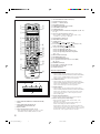
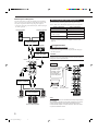
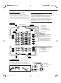
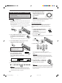
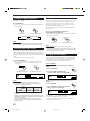
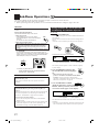
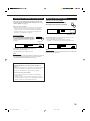
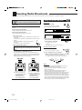
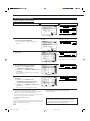
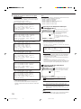
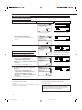
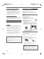
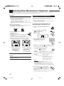
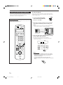
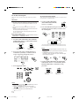
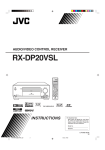
Remote Control
LEARN TRANSMIT
1
STANDBY
MAIN ROOM SUB ROOM
MAIN ROOM SUB ROOM
2
ON/OFF
y
ON
TV/CATV/DBS
VCR 1
STANDBY/ON
STANDBY/ON
u
ON/OFF
5
6
7
8
9
p
q
w
MAIN ROOM SUB ROOM LEARN
3
e
4
DVD
DVD MULTI
PHONO
CD
VCR 1
VCR 2
TAPE/MD
CDR
TV/DBS
VIDEO
FM
AM
1
2
ANALOG/DIGITAL
5
6
r
t
y
EFFECT
INPUT
3
ROOM SIZE
SOUND
4
5
6
LIVENESS
7
8
9
p
q
7/P
8
10
0
i
u
o
;
a
i
9
WALL
TEST
+10
RETURN
FM MODE
100+
SURROUND
DSP
THX
ON/OFF
MODE
ON/OFF
LINE DIRECT
CC CONVERTER
SLEEP
DIMMER
TV
s
CATV/
DBS
/ REW
PLAY
DOWN
TUNING
STOP
REC
FF/
d
UP
PAUSE
w
TV/VIDEO
TV VOL CHANNEL
f
VOLUME
MUTING
g
e
r
t
SETUP
MENU
ADJUST
MENU
TEXT
DISPLAY
SET
DVD
MENU
o
;
a
s
d
f
g
h
ANALOG/DIGITAL INPUT button (23)
SOUND button (49, 52, 64)
LEVEL +/ – buttons (49, 64)
TEST button (49, 64)
SURROUND ON/OFF button (48, 64)
LINE DIRECT button (25)
SLEEP button (26)
Operating buttons for audio/video components (31, 64 – 69,
71 – 73)
On-screen operation buttons (34, 42, 57)
• SETUP MENU, ADJUST MENU, SET, EXIT, % (UP),
fi (DOWN), @ (LEFT), # (RIGHT)
TEXT DISPLAY button (57)
DVD MENU button (66, 69)
AUDIO buttons
STANDBY (
), ON ( ) (18, 19, 20, 28 )
TV/CATV/DBS STANDBY/ON (
) button (66 – 68)
VCR 1 STANDBY/ON (
) (66, 68, 69)
• 10 keys for selecting preset channels (32)
• 10 keys for adjusting sound (49)
• 10 keys for adjusting DSP parameters (52)
• 10 keys for operating audio/video components
(64 – 73)
THX ON/OFF button (48)
DSP MODE button (51)
CC CONVERTER button (25)
TV operation mode selector (TV or CATV/DBS)
(66 – 68, 72)
DIMMER button (25)
VOLUME +/– buttons (18, 19, 22, 29)
MUTING button (24, 30)
LIGHT button (16)
EXIT
h
LIGHT
RM-SRXDP10J REMOTE CONTROL
A/V CONTROL RECEIVER
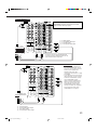
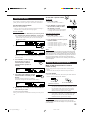
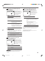
Remote’s display window
2
1
3
4
MAIN ROOM SUB ROOM LEARN
5
1 MAIN ROOM/SUB ROOM (LEARN/TRANSMIT)
selector
2 MAIN ROOM ON/OFF button (21)
SUB ROOM ON/OFF button (28)
3 Display window
4 Source selecting buttons (18, 19, 21, 29)
• DVD, DVD MULTI, PHONO, CD, VCR 1, VCR 2,
TAPE/MD, CDR, TV/DBS, VIDEO, FM, AM
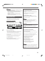
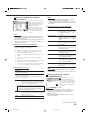
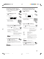
Remote’s display window
1 MAIN ROOM indicator
• Lights up when you press a button on the remote control,
with the MAIN ROOM/SUB ROOM (LEARN/TRANSMIT)
selector is set to “MAIN ROOM.” In this case, this remote
control can be used only for main room operations.
2 SUB ROOM indicator
• Lights up when you press a button on the remote control,
with the MAIN ROOM/SUB ROOM (LEARN/TRANSMIT)
selector set to “SUB ROOM.” In this case, this remote
control can be used only for sub-room operations.
3 LEARN indicator
• Lights up when you press a button on the remote control,
with the MAIN ROOM/SUB ROOM (LEARN/TRANSMIT)
selector set to “LEARN.” In this case, this remote control
cannot operate the receiver or other components, but can
memorize IR signals.
4 Signal transmission indicator
• Lights up when transmitting the remote control signals.
5 Remote control operation mode display
• Remote control operation mode such as “DVD,” “CD,”
“SOUND,” etc. appears.
When the remote control operation mode changes, it is
shown on this display for about 10 seconds.
(When showing the remote control operation mode just for
confirmation, it is shown only for about 5 seconds—i.e. when
pressing Number button 1 while the remote control operation
mode is “CD,” “CD” appears for about 5 seconds.)
5
EN01-16_RX-DP10VBK[J]_f
5
01.6.21, 5:36 PM
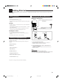
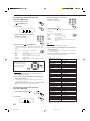
Getting Started
This section explains how to connect audio/video components and speakers to the receiver, and how to connect the
power supply.
Before Installation
General
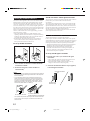
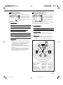
Connecting the FM and AM Antennas
FM Antenna Connections
• Be sure your hands are dry.
• Turn the power off on all components.
• Read the manuals supplied with the components you are going to
connect.
Extend the supplied FM antenna horizontally.
ANTENNA
AM
EXT
FM Antenna
Location
AM
LOOP
• Install the receiver in a location that is level, well-ventilated and
free from moisture.
• The temperature around the receiver must be between –5˚C and
35˚C (23˚F and 95˚F).
• Make sure there is good ventilation around the receiver. Poor
ventilation could overheat and damage the receiver.
FM 75
COAXIAL
Outdoor FM Antenna Cable
(not supplied)
Handling the receiver
• Do not insert any metal object into the receiver.
• Do not disassemble the receiver or remove screws, covers, or
cabinet.
• Do not expose the receiver to rain or moisture.
A
A
NN
TE
AN
B
AM
T
EX
AMP
O
LO
AMP
O
LO
75
FMAXIAL
75
FMAXIAL
CO
Checking the Supplied Accessories
Check to be sure you have all of the following items, which are
supplied for the receiver.
The number in the parentheses indicates quantity of the pieces
supplied.
• Remote Control (1)
A
NN
TE
AN
AM
T
EX
CO
AM P
O
LO
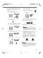
A. Using the Supplied FM Antenna
The FM antenna provided can be connected to the FM 75Ω
COAXIAL terminal as a temporary measure.
B. Using the Standard Type Connector with Outdoor FM
Antenna (not Supplied)
A standard type connector should be connected to the FM 75Ω
COAXIAL terminal.
• Batteries (2)
• AM Loop Antenna (1)
• FM Antenna (1)
Note:
• RF Rod Antenna (1)
• IR Signal Transmitter (1)
If reception is poor, connect the outdoor antenna.
Before attaching a 75Ω coaxial cable (the kind with a round wire going
to an outdoor antenna), disconnect the supplied FM antenna.
• Double-Sided Adhesive Tape (1)
• Front Terminal Cover (1)
If any item is missing, contact your dealer immediately.
6
EN01-16_RX-DP10VBK[J]_f
6
01.6.19, 0:25 PM
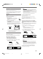
AM Antenna Connections
2
1
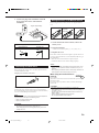
Connecting the Speakers
3
ANTENNA
AM
EXT
AM
LOOP
Turn the loop until you
have the best reception.
FM 75
COAXIAL
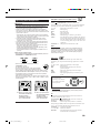
You can connect the following speakers:
• Two pairs of front speakers to produce normal stereo sound.
• One pair of surround speakers to enjoy the surround effect.
• One pair of surround back speakers to enjoy 7.1 channel sound
reproduction.
• One center speaker to produce more effective surround effect (to
emphasize human voices).
• One powered subwoofer to enhance the bass.
IMPORTANT:
After connecting the speakers listed above, set the speaker
setting information properly:
• To obtain the best possible Surround and DSP effect in the
main room, see “Basic Settings” on pages 33 to 40.
• To use the Multi-room function, see “Preparing for the
Sub-Room Operations—SUB ROOM” on page 40.
For each speaker (except for a subwoofer), connect the (+) and (–)
terminals on the rear panel to the (+) and (–) terminals marked on
the speakers. For connecting a subwoofer, see page 8.
CAUTION:
AM Loop Antenna
Use speakers with the SPEAKER IMPEDANCE indicated by the
speaker terminals.
Snap the tabs on the loop into
the slots of the base to
assemble the AM loop.
Main room speaker layout
Subwoofer
Outdoor single vinyl-covered wire (not supplied)
Notes:
• If the AM loop antenna wire is covered with vinyl,
remove the vinyl by twisting it as shown in the diagram.
• Make sure the antenna conductors do not touch any
other terminals, connecting cords and power cord. This
could cause poor reception.
• If reception is poor, connect an outdoor single vinyl-covered wire to
the AM EXT terminal. (Keep the AM loop antenna connected.)
Left front speaker(s)
Right front speaker(s)
Center speaker
Left surround
speaker
Right surround
speaker
Surround back speakers
Note:
When connecting the speakers for the sub-room, see also page 17.
7
EN01-16_RX-DP10VBK[J]_f
7
01.6.19, 0:25 PM
Basic connecting procedure
RIG
RIG
HT
LE
You can connect two pairs of front speakers—one pair to the FRONT
1 SPEAKERS terminals, and the other pair to the FRONT 2 / SUB
ROOM SPEAKERS terminals.
The speakers connected to the FRONT 2 / SUB ROOM SPEAKERS
terminals can be used as follows:
• As the second front speakers in the main room
• As the front speakers in the sub-room when using the Multi-room
operations. (See page 17.)
4
3
2
1
Note:
RIG
HT
FT
LE
HT
LE
FT
FT
CAUTION:
Use only the speakers of the SPEAKER IMPEDANCE indicated by
the speaker terminals.
1 Cut, twist and remove the insulation at the end of
each speaker signal cable (not supplied).
IMPORTANT for the FRONT 1 SPEAKERS connection:
2 Turn the knob counterclockwise.
To obtain the best possible output power from the receiver, and to
prevent the receiver from being overheated, the receiver has the
SPEAKER LOAD SELECTOR which has to be set as follows:
• Set it to the “HIGH” position when the impedance of the front
speakers connected is within the range of 8 Ω to 16 Ω.
• Set it to the “LOW” position when the impedance of the front
speakers connected is within the range of 4 Ω to 6 Ω.
3 Insert the speaker signal cable.
4 Turn the knob clockwise.
Front speakers 1
Right / Left
Center speaker
CAUTION :
SPEAKER IMPEDANCE
FRONT 1 SPEAKERS
FRONT 2 /
SUB ROOM SPEAKERS
CENTER
SPEAKER
8
16
SURROUND
SPEAKERS
SURROUND BACK
SPEAKERS
CAUTION :
SPEAKER
IMPEDANCE
LOW
4
6
+
HIGH
8
16
–
SPEAKER
LOAD SELECTOR
RIGHT
LEFT
RIGHT
LEFT
RIGHT
LEFT
RIGHT
Right / Left
Surround speakers
LEFT
Right / Left
Surround back
speakers
Right / Left
Front speakers 2
Connecting a subwoofer
You can enhance the bass by connecting a subwoofer.
Connect the input jack of a powered subwoofer to the
SUBWOOFER PREOUT jack on the rear panel, using a cable with
RCA pin plugs (not supplied).
FRONT
SUB
WOOFER
CENTER
SURR
Powered
subwoofer
SURR
BACK
R
L
PREOUT
8
EN01-16_RX-DP10VBK[J]_f
8
2001.6.27, 4:20 PM
Enhance your audio system
Connecting Audio/Video Components
You can use this receiver as the pre-amplifier (control amplifier)
when you connect power amplifiers to the PREOUT jacks on the
rear panel, using cables with RCA pin plugs (not supplied).
• Connect the white plug to the audio left jack, and the red plug to
the audio right jack.
Left front speaker
Right front speaker
You can connect the following audio/video components to this
receiver. Refer also to the manuals supplied with your components.
•
•
•
•
Audio Components
Turntable
CD player*
Cassette deck
or MD recorder*
CD recorder*
•
•
•
•
•
Video Components
DVD player*
TV*
DBS tuner*
VCRs (VCR1* and VCR2)
Video camera
* You can connect these components using the methods described in
“Analog connections” (below) and in “Digital connections” (see
page 14).
Power amplifier
Center speaker
Analog Connections
Audio component connections
Use the cables with RCA pin plugs (not supplied).
• Connect the white plug to the audio left jack, and the red plug to
the audio right jack.
Power amplifier
CAUTION:
If you connect a sound-enhancing device such as a graphic equalizer
between the source components and this receiver, the sound output
through this receiver may be distorted.
LEFT
RIGHT
FRONT
Turntable
AUDIO
SUB
WOOFER
RIGHT
LEFT
CENTER
If a ground cable is
provided for your
turntable, connect
the cable to the
screw marked (H)
on the rear panel.
SURR
SURR
BACK
R
L
PREOUT
PHONO
CD
OUT
(REC)
TAPE
MD
IN
(PLAY)
OUT
(REC)
Power amplifier
CDR
IN
(PLAY)
FRONT
Turntable
To audio output
DVD
SUB
WOOFER
SURR
(REAR)
Power amplifier
CENTER
R
Right surround
speaker
Left surround
speaker
Left / Right
Surround back speakers
9
L
Note:
The above connection is for a turntable with an MM (moving-magnet)
type cartridge.
Any turntables incorporating a small-output cartridge such as an MC
(moving-coil) type must be connected to this receiver through a
commercial head amplifier or step-up transformer. Direct connection
may result in insufficient volume.
9
EN01-16_RX-DP10VBK[J]_f
DVD
01.6.19, 0:25 PM
CD recorder
CD player
AUDIO
RIGHT
CD recorder
LEFT
PHONO
CD player
To audio input
To audio output
CD
AUDIO
RIGHT
OUT
(REC)
To audio output
LEFT
PHONO
TAPE
MD
CD
IN
(PLAY)
OUT
(REC)
OUT
(REC)
TAPE
MD
CDR
IN
(PLAY)
IN
(PLAY)
FRONT
OUT
(REC)
DVD
SUB
WOOFER
SURR
(REAR)
CENTER
CDR
IN
(PLAY)
FRONT
R
DVD
L
DVD
SUB
WOOFER
SURR
(REAR)
CENTER
Cassette deck or MD recorder
R
DVD
L
Cassette deck
To audio input
To audio output
AUDIO
RIGHT
LEFT
PHONO
If your audio components have a COMPU LINK or TEXT
COMPU LINK jack
• See page 54 for detailed information about the connection and
the COMPU LINK remote control system.
• See page 56 for detailed information about the connection and
the TEXT COMPU LINK remote control system.
CD
OUT
(REC)
TAPE
MD
IN
(PLAY)
OUT
(REC)
CDR
IN
(PLAY)
FRONT
DVD
SUB
WOOFER
SURR
(REAR)
CENTER
R
To audio input
DVD
L
MD recorder
To audio output
Note:
You can connect either a cassette deck or an MD recorder to the
TAPE/MD jacks. When connecting an MD recorder to the TAPE/MD
jacks, change the source name to “MD,” which will be shown on the
display when selected as the source. See “Changing the Source
Name” on page 25 for details.
10
EN01-16_RX-DP10VBK[J]_f
10
01.6.19, 0:25 PM
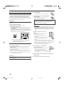
Video component connections
Use the cables with RCA pin plugs (not supplied).
Connect the white plug to the audio left jack, the red plug to the
audio right jack, and the yellow plug to the video jack.
• If your video components have S-video (Y/C-separation) and/or
component video (Y, PB/CB, PR/CR) jacks, connect them using an
S-video cable (not supplied) and/or component video cable (not
supplied). By using these jacks, you can get a better picture
quality—in the order : Component video > S-video > Composite
video.
IMPORTANT:
This receiver is equipped with the following video jacks—composite
video, S-video and component video jacks. You can use any of the
three to connect a video component.
However, the video signals from one type of these input jacks are
output only through the video output jacks of the same type.
Therefore, if a recording video component and a playing video
component are connected to the receiver through the video jacks of
the different type, you cannot record the picture. In addition, if the TV
and a playing video component are connected to the receiver through
the video jacks of the different type, you cannot view the playback
picture on the TV.
VCR(s)
D-VHS/S-VHS/VHS
VCR
A
C
B
E
D
Å
ı
Ç
Î
‰
Ï
Ì
F G
AUDIO
VIDEO
RIGHT
VIDEO
LEFT
To audio output
To audio input
To composite video output
To S-video output
To component video output
To composite video input
To S-video input
COMPONENT
S-VIDEO
Note:
TV SOUND
DBS
Y
OUT
(REC)
PB/CB
VCR1
1(DVD)
IN
(PLAY)
PR/CR
OUT
(REC)
Y
If your VCR has the component video
output jacks, you can connect it to either
the COMPONENT 1 (DVD) or the
COMPONENT 2 jacks.
When connecting a VCR to either one of
the component input jacks, make the
component input (COMPONENT) terminal
setting correctly. For details, see
“Preparing for the Component Video
Input—COMPONENT IN” on page 39.
VCR2
IN
(PLAY)
PB/CB
2
FRONT
PR/CR
DVD
IN
(PLAY)
PR/CR
OUT
(REC)
Y
Å
ı
Ç
Î
‰
Ï
VCR2
IN
(PLAY)
PB/CB
2
FRONT
PR/CR
DVD
A
S-VHS/VHS VCR
SUB
WOOFER
C
MONITOR
OUT
Y
MONITOR
OUT
PB/CB
To audio output
To audio input
To composite video output
To S-video output
To composite video input
To S-video input
D
CENTER
SURR
B
R
L
E
F
SURR
Video camera
The VIDEO input jacks on the front panel are convenient when
connecting and disconnecting the component frequently.
• When you do not use the VIDEO input jacks, attach the front
terminal cover (supplied) to these jacks to protect them from dust.
• When attaching the cover
To audio output
To composite video output
• When removing the cover
To S-video output
S-VIDEO
VIDEO
L—AUDIO—R
VIDEO
PU
SH
-O
P
S- EN
VID
EO
AV
CO
MP
U
VID
EO
VID
EO
LIN
K
L
AU
DIO
R
S-VIDEO
VIDEO
L—AUDIO—R
VIDEO
11
EN01-16_RX-DP10VBK[J]_f
11
01.6.19, 0:26 PM
TV and/or DBS tuner
AUDIO
VIDEO
RIGHT
VIDEO
LEFT
COMPONENT
S-VIDEO
TV SOUND
DBS
Y
OUT
(REC)
PB/CB
VCR1
1(DVD)
IN
(PLAY)
PR/CR
OUT
(REC)
Y
When connecting the TV to the AUDIO jacks (TV
SOUND/DBS), DO NOT connect the TV’s video
output to these video input jacks.
VCR2
IN
(PLAY)
PB/CB
2
FRONT
MONITOR
OUT
Y
SURR
MONITOR
OUT
PB/CB
SURR
BACK
PREOUT
SUB
WOOFER
Å
ı
Ç
Î
PR/CR
DVD
CENTER
A
TV
R
R
To audio output
To composite video input
To S-video input
To component video input
L
PR/CR
MONITOR OUT
SUB
ROOM
L
PREOUT
B
Connect the TV to the appropriate MONITOR
OUT jacks to view the playback picture from the
other connected video components.
C
D
Notes:
AUDIO
VIDEO
RIGHT
VIDEO
LEFT
COMPONENT
S-VIDEO
TV SOUND
DBS
Y
OUT
(REC)
PB/CB
VCR1
1(DVD)
IN
(PLAY)
PR/CR
OUT
(REC)
Y
VCR2
IN
(PLAY)
PB/CB
2
FRONT
PR/CR
DVD
MONITOR
OUT
Y
SURR
MONITOR
OUT
PB/CB
SURR
BACK
PREOUT
SUB
WOOFER
CENTER
A
R
DBS tuner
R
L
PREOUT
DBS
• When connecting the DBS tuner to
the TV SOUND/DBS jacks, change
the source name to “DBS,” which will
be shown on the display when
selected as the source. See
“Changing the Source Name” on page
25 for details.
• If your DBS tuner has the component
video output jacks, you can connect it
to either the COMPONENT 1 (DVD)
or the COMPONENT 2 jacks.
When connecting the DBS tuner to
either one of the component input
jacks, make the component input
(COMPONENT) terminal setting
correctly. For details, see “Preparing
for the Component Video Input—
COMPONENT IN” on page 39.
L
PR/CR
SUB
ROOM
MONITOR OUT
B
C
D
Å
ı
Ç
Î
To audio output
To composite video output
To S-video output
To component video output
12
EN01-16_RX-DP10VBK[J]_f
12
01.6.19, 0:26 PM
DVD player
• When you connect the DVD player with stereo output jacks:
AUDIO
RIGHT
LEFT
VIDEO
RIGHT
VIDEO
LEFT
TV SOUND
DBS
PHONO
CD
OUT
(REC)
COMPONENT
S-VIDEO
TAPE
MD
IN
(PLAY)
Y
OUT
(REC)
PB/CB
VCR1
1(DVD)
IN
(PLAY)
PR/CR
OUT
(REC)
Y
VCR2
OUT
(REC)
IN
(PLAY)
PB/CB
CDR
2
IN
(PLAY)
FRONT
FRONT
SUB
WOOFER
PR/CR
DVD
MONITOR
OUT
Y
SURR
MONITOR
OUT
PB/CB
SURR
BACK
PREOUT
CENTER
SUB
WOOFER
CENTER
R
R
L
DVD
R
PR/CR
B
MONITOR OUT
SUB
ROOM
L
PREOUT
A
L
D
C
DVD
Note:
If your DVD player has the component video
output jacks, you can connect it to either the
COMPONENT 1 (DVD) or the
COMPONENT 2 jacks.
When connecting the DVD player to either
one of the component input jacks, make the
component input (COMPONENT) terminal
setting correctly. For details, see “Preparing
for the Component Video Input—
COMPONENT IN” on page 39.
Å To front left/right channel audio
output (or to audio mixed output if
necessary)
ı To composite video output
Ç To S-video output
Î To component video output
DVD player
• When you connect the DVD player with its analog discrete output
(5.1 CH reproduction) jacks:
AUDIO
RIGHT
LEFT
VIDEO
RIGHT
VIDEO
LEFT
TV SOUND
DBS
PHONO
CD
OUT
(REC)
COMPONENT
S-VIDEO
TAPE
MD
IN
(PLAY)
Y
OUT
(REC)
PB/CB
VCR1
1(DVD)
IN
(PLAY)
PR/CR
OUT
(REC)
Y
Note:
VCR2
OUT
(REC)
IN
(PLAY)
PB/CB
CDR
2
IN
(PLAY)
FRONT
FRONT
SUB
WOOFER
DVD
MONITOR
OUT
Y
MONITOR
OUT
PB/CB
CENTER
SURR
SUB
WOOFER
SURR
(REAR)
CENTER
R
SURR
BACK
R
L
DVD
B
C
D
L
PR/CR
PREOUT
R
E
F
MONITOR OUT
SUB
ROOM
L
PREOUT
A
PR/CR
DVD
G
If your DVD player has the component video
output jacks, you can connect it to either the
COMPONENT 1 (DVD) or the COMPONENT
2 jacks.
When connecting the DVD player to either
one of the component input jacks, make the
component input (COMPONENT) terminal
setting correctly. For details, see “Preparing
for the Component Video Input—
COMPONENT IN” on page 39.
Å
ı
Ç
Î
‰
Ï
Ì
To left/right front channel audio output
To subwoofer output
To left/right surround channel audio output
To center channel audio output
To composite video output
To S-video output
To component video output
DVD
DVD player
13
EN01-16_RX-DP10VBK[J]_f
13
01.6.19, 0:26 PM
Notes:
Digital Connections
This receiver is equipped with five DIGITAL IN terminals—one
digital coaxial terminal and four digital optical terminals—and one
DIGITAL OUT terminal.
IMPORTANT:
• When connecting the DVD player, digital TV broadcast tuner, digital
VCR, or DBS tuner using the digital terminals, you also need to
connect it to the video terminal on the rear. Without connecting it to
the video terminal, you cannot view any playback picture.
• After connecting the components using the DIGITAL IN terminals,
set the following correctly if necessary.
– Set the digital input (DIGITAL IN) terminal setting correctly. For
details, see “Setting the Digital Input Terminals—DIGITAL IN” on
page 38.
– Select the digital input mode correctly. For details, see “Selecting
the Analog or Digital Input Mode” on page 23.
• When shipped from the factory, the DIGITAL IN terminals have
been set for use with the following components:
– DIGITAL 1 (coaxial): For DVD player
– DIGITAL 2 (optical): For CD player
– DIGITAL 3 (optical): For digital TV broadcast tuner
– DIGITAL 4 (optical): For CD recorder
– DIGITAL 5 (optical): For MD recorder
• When you want to operate the CD player, CD recorder, or MD
recorder using the COMPU LINK remote control system, connect
the target component also as described in “Analog connections”
(see page 10).
• When you want to operate the VCR or DVD player using the AV
COMPU LINK remote control system, connect the target
component also as described in “Analog connections” (see pages
11, 13).
• To use the digital source components as the sub-room source,
connect them using analog connection methods as well.
Digital output terminal
Digital input terminals
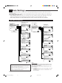
You can connect any digital component as follows:
Digital TV
CD recorder
MD recorder
DBS tuner
DBS
Digital optical cable (not supplied)
between digital optical terminals
Digital VCR
DVD player
CD player
DVD
CD recorder
MD recorder
Digital coaxial cable (not supplied)
between digital coaxial terminals
Digital optical cable (not supplied)
between digital optical terminals
When the digital recording
equipment such as an MD recorder
and a CD recorder has a digital
optical input terminal, connecting it
to the DIGITAL OUT terminal
enables you to perform digital-todigital recording.
PCM
/ DOLBY DIGITAL
/ DTS
DIGITAL OUT
Note:
The digital signal format of the signals output through the DIGITAL
OUT terminal is the same as that of the input signal. This means that
when the DTS Surround signals are input, the DTS Surround signals
are output.
When the component has a digital
coaxial output terminal, connect it to the
DIGITAL 1 (DVD) terminal, using the
digital coaxial cable (not supplied).
DIGITAL IN
When the component has a digital
optical output terminal, connect it to the
DIGITAL 2 (CD), DIGITAL 3 (TV),
DIGITAL 4 (CDR), or DIGITAL 5 (MD)
terminal, using the digital optical cable
(not supplied).
Before connecting a digital
optical cable, unplug the
protective plug.
DIGITAL 1 (DVD)
DIGITAL 2 (CD)
DIGITAL 3 (TV)
DIGITAL 4 (CDR)
DIGITAL 5 (MD)
14
EN01-16_RX-DP10VBK[J]_f
14
01.6.19, 0:26 PM
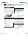
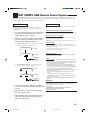
The RF rod antenna and IR signal Transmitter
Setting Up the RF Rod Antenna
The remote control supplied for this receiver can transmit both RF
(Radio Frequency) signal as well as IR (infrared) signal. The RF
rod antenna can receive the RF signals emitted from the remote
control. So, with the RF rod antenna connected, you can operate the
receiver at a distance of up to 15 m (50 feet) using RF signals sent
from this receiver (more than twice as far as when using IR signals).
Moreover, RF signals can go through walls and other objects in the
house so you need not aim at the receiver directly.
However, if the antenna cannot receive signals stably, you cannot
operate the receiver correctly.
• The signal-reachable distance may differ depending on the
operating conditions and circumstances. To improve transmitting
conditions, change the distance to the receiver and the direction
to transmit while operating the remote control.
• Without the RF rod antenna connected, you can operate the
receiver with the remote control, aiming the remote control
directly at the remote sensor on the receiver.
To set up the RF rod antenna
2
1
RF
RF
RE
MO
AN
TE
AN
TE
NN
RE
TE
A
NN
MO
TE
The combination of the RF rod antenna and the IR signal transmitter
(below) allows you to use the Multi-room function more
conveniently.
The remote control supplied for this receiver can transmit both RF
signal and IR signal at the same time. This receiver catches the RF
signals emitted from the remote control, and converts them into IR
signals, then transmits the converted signals to the remote sensor on
the other components through IR signal transmitter.
This means that you can control not only this receiver but also the
other components from the sub-room.
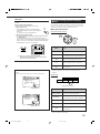
Setting Up the IR Signal Transmitter
The IR signal transmitter can transmit the IR signals.
It allows you to use the AV COMPU LINK system, and to operate
other manufacturers’ components without aiming the remote control
directly at the remote sensor on the target components. In addition,
the IR signal transmitter reduces the possibility of malfunction.
• The IR signal transmitter may not operate the target components
depending on the operating conditions and circumstances—
including the aiming angle and direction of the IR signal
transmitter at the remote sensors of the target components. If
this occurs, changing its aiming angle and direction at the
remote sensors may solve the problem.
A
To set up the IR signal transmitter
BA
IR
BA
ND
BA 1
ND
2
IR
OU
T
ND
BA 1
ND
2
OU
T
1. Insert the RF rod antenna to the RF REMOTE
ANTENNA terminal.
2. Rotate the fixing nut to attach the RF rod
antenna firmly.
1. Find the place where you attach the IR signal
transmitter.
• Place it where the signal can reach the remote sensor of the
target components directly (in the line-of-sight).
• If the cord length of the IR signal transmitter is not long
enough, use an extension cord (not supplied).
2. Attach the double-sided adhesive tape (supplied)
to the IR signal transmitter.
IR signal transmitter
Notes:
• To avoid a failure in the reception from the remote control, keep the
connecting cables and the IR signal transmitter’ s cable away from
the RF rod antenna.
• If your neighbour uses the same or similar RF remote control
system, the receiver may happen to receive the RF signals sent
from such an RF remote control system, which could cause your
receiver to be operated unintentionally. If this happens, set the
BAND selectors (both on the rear and on the remote control) to
another band (either BAND 1 or BAND 2).
RF
Double-sided
adhesive tape
REMOTE
ANTENNA
BAND1
1 2
BAND2
On the main unit’s rear
On remote control
(Inside the battery compartment)
If the problem still persists, stop using the RF rod antenna and the
remote control, and consult your JVC dealer or the nearest JVC
Service Center.
15
EN01-16_RX-DP10VBK[J]_f
15
01.6.19, 0:26 PM
3. Connect the plug of the transmitter to the IR
OUT jack of the receiver and attach the
transmitter.
RF
Putting Batteries in the Remote Control
Before using the remote control, insert the two supplied batteries
first.
REMOTE
Target component(s)
ANTENNA
2
1
BAND1
3
LR6(AM3)
/L40(15A)
BAND2
s
es
L
an
th
3
m
IR OUT
0
(1
)
et
fe
At an angle of
approx. 60°
1. On the back of the remote control, remove the
battery cover.
Signal-emitting angle of the transmitter
Horizontally: 60˚
Vertically: 60˚
2. Insert the batteries.
• Make sure to match the polarity: (+) to (+) and (–) to (–).
15°
45°
30°
30°
3. Replace the cover.
If the remote control cannot transmit signals or operate the receiver
correctly, replace the batteries. Use two LR6(AM3)/L40(15A) type
dry-cell batteries.
• When the remote control transmits a signal, the signal
transmission indicator on the remote’s display lights up.
Notes:
Connecting the Power Cord
Before plugging the receiver into an AC outlet, make sure that all
connections have been made.
Plug the power cord into an AC outlet.
• If you aim the remote control directly at the remote sensor on the
receiver, you can operate the receiver at a distance of up to 7 m
(23 feet).
• When replacing the batteries, finish it without delay; otherwise, the
stored signals are all erased (see pages 67 and 71).
When using the remote control in
the dark
LIGHT
Press LIGHT.
The buttons on the remote control are backlit while you are using
the remote control.
If you do not press any button for about 5 seconds, the backlight
will turn off.
CAUTIONS:
Keep the power cord away from the connecting cables and the
antenna. The power cord may cause noise or screen interference.
We recommend that you use a coaxial cable to connect the antenna,
since it is well-shielded against interference.
Note:
The preset settings such as preset channels and sound adjustment
may be erased in a few days in the following cases:
– When you unplug the power cord.
– When a power failure occurs.
Follow these precautions to avoid leaking or cracking cells:
• Place batteries in the remote control so they match the polarity: (+)
to (+) and (–) to (–).
• Use the correct type of batteries. Batteries that look similar may
differ in voltage.
• Always replace both batteries at the same time.
• Do not expose batteries to heat or flame.
CAUTIONS:
• Do not touch the power cord with wet hands.
• Do not pull on the power cord to unplug the cord.
When unplugging the cord, always grasp the plug so as not to
damage the cord.
16
EN01-16_RX-DP10VBK[J]_f
16
01.6.19, 0:26 PM
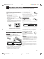
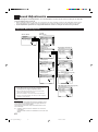
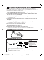
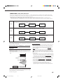
Multi-Room Operations
Before operating this receiver any further, be familiar with this Multi-room function.
This function enables you to listen to different sources in two different places (we call these two places “main room”
and “sub-room”) by using this receiver.
This section explains only the required speaker connections, the concept, and basic operations of the Multi-room
function. For more detailed operations, see the respective pages in this manual.
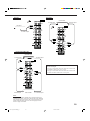
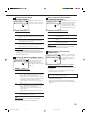
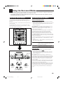
Required Connections for Sub-Room
1. Connect a TV to the SUB ROOM MONITOR OUT jack (either composite video or S-video jack).
2. Connect front speakers by using one of the methods described below (either Connection Å or Connection ı).
Sub-room Layout
TV
To use the sub-room TV.
Turn on and select the correct input for this
receiver.
Right front speaker
Left front speaker
Connection Å
Connect the input jacks of another amplifier to the
SUB ROOM PREOUT jacks on the rear panel, using
a cable with RCA pin plugs (not supplied).
Connection ı
See also page 8.
CAU
SPE
Power amplifier
FRONT 1 SPEAKERS
MONITOR
OUT
C
S
CAUTION :
SPEAKER
IMPEDANCE
Y
LOW
4
MONITOR
OUT
FRONT 2 /
SUB ROOM SPEAKERS
6
HIGH
8
16
PB/CB
R
L
SPEAKER
LOAD SELECTOR
PR/CR
PREOUT
SUB
ROOM
RIGHT
LEFT
RIGHT
LEFT
MONITOR OUT
Merits:
• This connection DOES NOT require a power amplifier.
Merits:
• This connection DOES allow you to always use the
Surround/DSP mode using the center, surround, and
surround back speakers (see pages 46 and 50) and the DVD
MULTI playback mode (see page 53) for the main room
sources.
• The output level through the SUB ROOM PREOUT jacks
can either be fixed or be variable by setting it on the Setup
Menu. (See “Preparing for the Sub-Room Operations—SUB
ROOM” on page 40 for more details.)
Demerits:
• This connection DOES require another amplifier.
Demerits:
• When the sub-room speakers are activated, this connection
DOES NOT allow you to use the Surround/DSP modes using
the center, surround, and surround back speakers (see pages
46 and 50) and the DVD MULTI playback mode (see page
53) for the main room sources.
• When the Surround/DSP modes using the center, surround,
and surround back speakers or when the DVD MULTI
playback mode is activated for the main room sources, this
connection DOES NOT allow you to use the sub-room
speakers.
To use the sub-room front speakers.
Turn on and operate the other amplifier connected to the SUB
ROOM PREOUT jacks correctly.
To use the sub-room front speakers connected to the FRONT
2/SUB ROOM SPEAKERS terminals
See “Preparing for the Sub-Room Operations—SUB ROOM” on
page 40, and “Activating the Sub-Room Front Speakers” on page
30.
Note:
Note:
Usage of long audio cables/long speaker signal cables will
deteriorate the signals and degrade the sound quality.
Usage of long speaker signal cables will deteriorate the signals
and degrade the sound quality.
17
EN17-30_RX-DP10VBK[J]_f
17
2001.6.27, 4:21 PM
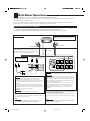
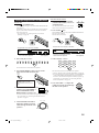
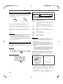
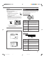
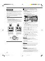
Basic Operating Procedure for Main Room
1. Set MAIN ROOM/SUB ROOM
(LEARN/TRANSMIT) selector to
“MAIN ROOM.”
On the unit:
1. Press
From the remote control:
(STANDBY/ON).
The STANDBY lamp goes off, and the MAIN ROOM ON/OFF
lamp lights up.
The front door moves down so that the source selecting buttons
appear, and the buttons and controls on the unit work for the
main room operations.
• For more details, see “Turning the Power On and Off
(Standby)” on page 20.
LEARN TRANSMIT
MAIN ROOM SUB ROOM
Now the buttons and controls on the remote
control work for the main room operations.
2. Press AUDIO (ON).
The STANDBY lamp goes off, and the MAIN ROOM ON/OFF
lamp on the unit lights up.
The front door moves down.
STAN
DBY
STAN
DBY
STAN
DBY
/ON
STAN
DBY
CC
/ON
CC
STANDBY
CON
VER
TER
CON
VER
TER
MAIN
ROO
ON/O M
FF
MAIN
ROO
ON/O M
FF
SUB
D
IG
SU
IG
IT
RR
A
OU
ROO
ON/O M
FF
L
I G
I T
A
DVD
L
DVD
PHO
NES
MUL
TI
MAIN ROOM
ON/OFF
STANDBY/ON
STANDBY
ND
D
A
OU
ROO
ON/O M
FF
L
ND
D
SUB
D
SU
IT
RR
ON
VTR
INPU
T MOD
2
2
TV
E
INPU
T
SURR
ON OUN
/ OFFD
ATT
RX
-D
P1
0V
/ DBS
VIDE
O
DSP
ONHTX
/ OFF
MOD
E
CD
LINE
DIRE
CT
AU
DIO
/VI
DE
O
SOU
SELE
ND
CTOR
REC
SELE
CTOR
I
T
A
DVD
L
DVD
MUL
TI
MAIN ROOM
ON/OFF
1
1
SPEA
KERS
G
PHO
NES
VTR
SPEA
KERS
I
MEN
U
SETU
P MEN
TAP
E/
DOW
N
2
TV
E
INPU
T
ATT
SURR
ON OUN
/ OFFD
ONHTX
/ OFF
RX
-D
P1
0V
/ DBS
VIDE
O
DSP
MOD
E
LINE
DIRE
CT
AU
DIO
/VI
DE
O
MER
MAS
CDR
TER
VOL
LEFT
VTR
INPU
T MOD
2
DIM
MD
U
CO
NT
RO
L RE
CE
IVE
R
1
1
SPEA
KERS
PHO
NO
ADJU
ST
VTR
SPEA
KERS
UME
TUN
ER
UP
EXT
RIGH
T
7.1C
H
SET
DOO
R
UP
CD
SOU
SELE
ND
CTOR
REC
SELE
CTOR
PHO
NO
ADJU
ST
MEN
U
SETU
P MEN
TAP
E/
DOW
N
DIM
MD
MER
MAS
CDR
TER
U
CO
NT
RO
L RE
CE
IVE
R
VOL
LEFT
UP
RIGH
T
UME
TUN
ER
DOO
R
UP
EXT
SET
7.1C
H
EXIT
DOO
R
DOW
N
EXIT
DOO
R
DOW
N
PUS
H-O
PEN
S-VI
DEO
VIDE
O
VIDE
O
PUS
H-O
PEN
S-VI
DEO
VIDE
O
VIDE
O
L
AUD
IO
R
L
AUD
IO
R
The last main room source is activated.
The last main room source is activated.
ANALOG
ANALOG
L
SPEAKERS
R
L
1
SPEAKERS
R
1
VOLUME
SUBWFR
VOLUME
SUBWFR
dB
dB
The volume
level appears.
The last Surround/DSP mode or
other information appears.
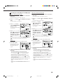
3. Select and play a source.
2. Select and play a source.
DVD
DVD MULTI
VCR 1
VCR 2
TV/DBS
VIDEO
The volume
level appears.
The last Surround/DSP mode or
other information appears.
CD
PHONO
TAPE/MD
CDR
FM
AM
DVD
DVD MULTI
PHONO
CD
VCR 1
VCR 2
TAPE/MD
CDR
TV/DBS
VIDEO
FM
AM
The sound comes out of the main room speakers.
3. Press DOOR DOWN so that you can use the
other buttons inside the front door.
The sound comes out of the main room front speakers.
• See also “Turning the Power On and Off (Standby)” on page 20.
• If no sound comes out of the front speakers, press SPEAKERS
1 and/or SPEAKERS 2/SUB ROOM on the unit (inside the
front door). The selected front speaker indicator(s) light(s) up
on the display. For more details, see “Activating the Main
Room Front Speakers” on page 23.
DOOR
DOWN
STAN
DBY
STAN
DBY
/ON
CC
CON
VER
TER
MAIN
ROO
ON/O M
FF
SUB
D
IG
SU
IT
RR
A
OU
ROO
ON/O M
FF
L
ND
D
I G
I T
A
L
PHO
NES
SPEA
KERS
1
SPEA
/ SUBKERS
ROO
M2
DVD
INOU
/ INPPT
MOD
UT
E
ATT
MUL
TI
RX
-D
P1
0V
SURR
ON OUN
/ OFFD
SUB
CONROO
TROM
L
DVD
DSP
ONHTX
/ OFF
VCR
MOD
E
1
LINE
DIRE
CT
VCR
To close the front door, press
DOOR UP once or twice.
The front door moves up in two
steps.
2
SOU
SELE
ND
CTOR
FM
TV
ADJU
MOD
ST
E
/ DBS
MEN
U
SETU
P MEN
VIDE
O
DIM
MER
MAS
DOW
TER
N
U
VOL
LEFT
CD
UME
UP
RIGH
PHO
NO
DOO
R
UP
SET
T
TAP
E/
EXIT
MD
DOO
R
DOW
N
CDR
AU
DIO
/VIDE
FM
O CO
NT
AM
RO
L RE
CE
IVE
R
4. Press VOLUME +/– to adjust the
volume level of the sound through
the main room speakers.
PUS
H-O
PEN
S-VI
DEO
VIDE
O
VIDE
O
L
AUD
IO
R
4. If no sound comes out of the front
speakers, press SPEAKERS 1
and/or SPEAKERS 2/SUB
ROOM which you want to use.
VOLUME
SPEAKERS 1
SPEAKERS 2
/ SUB ROOM
The selected front speaker indicator(s) light(s) up on the display.
• For more details, see “Activating the Main Room Front
Speakers” on page 23.
MASTER VOLUME
5. Turn MASTER VOLUME to
adjust the volume level of the
sound through the main room
speakers.
Down
Up
18
EN17-30_RX-DP10VBK[J]_f
18
01.6.19, 1:13 PM
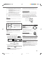
Basic Operating Procedure for Sub-Room
The sources and functions available for the sub-room
operations are limited.
For more details on the sub-room operations, see “Sub-Room
Operations” on pages 27 to 30.
MASTER VOLUME
Down
Note:
On the unit:
1. Press
6. Turn MASTER VOLUME to
adjust the volume level of the
sound through the sub-room
front speakers.
(STANDBY/ON).
The STANDBY lamp goes off, and the MAIN ROOM ON/OFF
lamp lights up.
The front door moves down so that the source selecting buttons
appear, and the buttons and controls on the unit work for the
main room operations.
• For more details, see “Turning the Power On and Off (Standby)
and Selecting the Sub-Room Operations” on page 27.
Up
When connecting the sub-room front speakers to the SUB ROOM
PREOUT jacks, the MASTER VOLUME control will not be able to
adjust the volume (see “Preparing for the Sub-Room
Operations—SUB ROOM” on page 40).
From the remote control:
When operating the receiver using the remote control, the
display on the unit always shows the main room source
information though you are operating it for the sub-room
source.
STAN
DBY
STANDBY
STAN
DBY
/ON
CC
1. Set MAIN ROOM/SUB ROOM
(LEARN/TRANSMIT) selector to
“SUB ROOM.”
CON
VER
TER
MAIN
ROO
ON/O M
FF
SUB
D
IG
SU
IT
RR
A
OU
ROO
ON/O M
FF
L
ND
D
I
G
I
T
A
DVD
L
DVD
PHO
NES
STANDBY/ON
MUL
TI
MAIN ROOM
ON/OFF
VTR
SPEA
KERS
1
1
SPEA
KERS
VTR
INPU
T MOD
2
2
TV
E
INPU
T
SURR
ON OUN
/ OFFD
ATT
RX
-D
P1
0V
/ DBS
VIDE
O
DSP
ONHTX
/ OFF
MOD
E
CD
LINE
DIRE
CT
AU
DIO
/VI
DE
O
SOU
SELE
ND
CTOR
REC
SELE
CTOR
PHO
NO
ADJU
ST
MEN
U
SETU
P MEN
TAP
E/
DIM
MD
DOW
N
MER
MAS
CDR
TER
U
CO
NT
RO
L RE
CE
IVE
R
VOL
LEFT
UME
TUN
ER
UP
EXT
RIGH
T
7.1C
H
SET
DOO
R
UP
EXIT
LEARN TRANSMIT
MAIN ROOM SUB ROOM
Now the buttons and controls on the remote
control work for the sub-room operations.
DOO
R
DOW
N
PUS
H-O
PEN
S-VI
DEO
VIDE
O
VIDE
O
L
AUD
IO
R
2. Press AUDIO (ON).
2. Press SUB ROOM ON/OFF so that the
SUB ROOM ON/OFF lamp lights up.
SUB ROOM
ON/OFF
The STANDBY lamp on the unit goes off, and the SUB ROOM
ON/OFF lamp on the unit lights up.
The sound comes out of the sub-room front
speakers.
• If no sound comes out of the front speakers, see page 17.
STAN
DBY
STAN
DBY
/ON
CC
CON
VER
TER
MAIN
STANDBY
ROO
ON/O M
FF
ON
SUB
D
IG
SU
IT
RR
A
OU
ROO
ON/O M
FF
L
ND
D
I
G
I
T
A
DVD
L
DVD
PHO
NES
MUL
TI
SUB ROOM
ON/OFF
3. Press DOOR DOWN so that you can use the
other buttons inside the front door.
VTR
SPEA
1
KERS
1
SPEA
VTR
INPU
KERS
2
T MOD
2
TV
E
INPU
T
ATT
SURR
ON OUN
/ OFFD
ONHTX
/ OFF
RX
-D
P1
0V
/ DBS
VIDE
O
DSP
MOD
CD
E
LINE
DIRE
CT
AU
DIO
/VI
DE
O
SOU
SELE
ND
CTOR
REC
SELE
CTOR
PHO
NO
ADJU
ST
MEN
U
SETU
TAP
E/
DOW
P MEN
N
DIM
MD
MER
MAS
CDR
TER
U
CO
NT
RO
L RE
CE
IVE
R
VOL
LEFT
UME
TUN
ER
UP
EXT
RIGH
T
SET
7.1C
H
DOO
R
UP
EXIT
DOO
R
DOW
N
PUS
H-O
PEN
S-VI
DEO
DOOR
DOWN
VIDE
O
VIDE
3. Select and play a source.
O
L
AUD
IO
R
STAN
DBY
STAN
DBY
/ON
CC
CON
VER
TER
MAIN
ROO
ON/O M
FF
DVD
DVD MULTI
PHONO
CD
VCR 1
VCR 2
TAPE/MD
CDR
TV/DBS
VIDEO
FM
AM
SUB
D
IG
SU
IT
RR
A
OU
ROO
ON/O M
FF
L
ND
D
I G
I T
A
L
PHO
NES
SPEA
KERS
1
SPEA
/ SUBKERS
ROO
M2
DVD
INOU
/ INPPT
MOD
UT
E
ATT
MUL
TI
RX
-D
P1
0V
SURR
ON OUN
/ OFFD
SUB
CONROO
TROM
L
DVD
DSP
ONHTX
/ OFF
VCR
MOD
E
1
LINE
DIRE
CT
VCR
2
SOU
SELE
ND
CTOR
FM
TV
/ DBS
MOD
E
ADJU
ST
MEN
U
SETU
DIM
MER
MAS
DOW
P MEN
VIDE
O
VOL
LEFT
To close the front door, press
DOOR UP once or twice.
The front door moves up in two steps.
TER
N
U
CD
UME
UP
RIGH
PHO
NO
SET
T
TAP
E/
DOO
R
UP
EXIT
MD
DOO
R
DOW
N
CDR
AU
DIO
/VIDE
FM
O CO
NT
AM
RO
L RE
CE
IVE
R
PUS
H-O
PEN
S-VI
DEO
VIDE
O
VIDE
O
L
AUD
IO
R
4. Press SUB ROOM CONTROL so
that “SUB ROOM” and the
previously selected sub-room
source name appear on the display.
The sound comes out of the sub-room front speakers.
• If no sound comes out of the front speakers, see page 17.
SUB ROOM
CONTROL
Notes:
Now the buttons and controls on the unit work for the sub-room
operations.
SPEAKERS
1
• You cannot select DVD MULTI as a source for the sub-room.
• When “TV” has been assigned as the source name to the TV/
DBS button, it does not work. To change the source name, see
“Changing the Source Name” on page 25.
SUB ROOM
VOLUME
dB
The last sub-room source appears.
5. Select and play a source.
DVD
DVD MULTI
VCR 1
VCR 2
TV/DBS
VIDEO
CD
The sub-room volume
level appears.
PHONO
TAPE/MD
CDR
FM
4. Press VOLUME +/– to adjust the
volume level of the sound through
the sub-room front speakers.
VOLUME
AM
Note:
Notes:
• You cannot select DVD MULTI as a source for the sub-room.
• When “TV” has been assigned as the source name to the TV/
DBS button, it does not work. To change the source name, see
“Changing the Source Name” on page 25.
When connecting the sub-room front speakers to the SUB ROOM
PREOUT jacks, the VOLUME +/– buttons will not be able to adjust
the volume (see “Preparing for the Sub-Room Operations—SUB
ROOM” on page 40).
19
EN17-30_RX-DP10VBK[J]_f
19
01.6.19, 1:13 PM
Main Room Operations
This section explains only the operations commonly used when you play any sound source in the main room.
See pages 27 to 30 for the sub-room operations.
• Before performing main room operations, it is recommended to finish the basic settings on pages 33 to 40.
IMPORTANT:
To turn off the power (into standby mode),
STANDBY
press
(STANDBY/ON) again.
The STANDBY lamp lights up, and the front
STANDBY/ON
door automatically closes. (The MAIN ROOM
ON/OFF and/or SUB ROOM ON/OFF lamp
goes off.)
• A small amount of power is consumed in standby mode. To turn
the power off completely, unplug the AC power cord.
Check to see if the following before or while using the buttons and
controls.
For the main room operations:
The MAIN ROOM ON/OFF lamp on the unit is lit.
• When using the unit:
– “SUB ROOM” is not shown in the main display.
– Press DOOR DOWN to use the buttons inside the
front door.
To close the front door, press DOOR UP.
DOOR
DOWN
• When using the remote control:
– Set the MAIN ROOM/SUB ROOM (LEARN/TRANSMIT) selector
to “MAIN ROOM.”
– Check the indication shown on the remote’s display when you
press a button—this indicates the remote control operation mode
together with multi-room operation mode (either MAIN ROOM or
SUB ROOM) for a while (10 or 5 seconds).
The last main room source is activated.
LEARN TRANSMIT
STANDBY
ON
MAIN ROOM SUB ROOM
MAIN ROOM SUB ROOM TV/CATV/DBS
LEARN TRANSMIT
ON/OFF
From the remote control:
To turn on the power, press
STANDBY
ON
AUDIO (ON).
The STANDBY lamp goes off, and the
MAIN ROOM ON/OFF lamp on the unit
lights up.
The front door moves down (so that the source selecting buttons
appear).
ANALOG
VCR 1
L
ON/OFF
STANDBY/ON
SPEAKERS
R
1
VOLUME
SUBWFR
STANDBY/ON
dB
MAIN ROOM
MAIN ROOM SUB ROOM
The last Surround/DSP mode or
other information appears.
Ex. When you press FM with
MAIN ROOM/SUB ROOM (LEARN/TRANSMIT)
selector set to “MAIN ROOM.”
The currently selected speakers 1 and/or 2 indicator(s) also light(s)
up on the display.
• If neither speakers 1 nor 2 indicator is lit on the display, see
“Activating the Main Room Front Speakers” on page 23.
Turning the Power On and Off (Standby)
On the unit:
To turn on the power, press
(STANDBY/ON).
The STANDBY lamp goes off, and the MAIN ROOM ON/OFF
lamp lights up. The front door moves down (so that the source
selecting buttons appear).
STANDBY
/ON
CC
CON
VER
TER
MAIN
ROO
ON/O M
FF
SUB
IG
IT
RR
A
OU
ROO
ON/O M
FF
L
ND
D
STANDBY / ON
I
G
I
T
A
DVD
L
PHO
NES
MAIN ROOM
ON/OFF
DVD
MUL
TI
VTR
SPEA
KERS
1
1
SPEA
KERS
VTR
INPU
T MOD
2
2
TV
E
INPU
T
ATT
SURR
ON OUN
/ OFFD
ONHTX
/ OFF
RX
-D
P1
0V
/ DBS
VIDE
O
DSP
MOD
E
LINE
DIRE
CT
AU
DIO
/VI
DE
O
CD
SOU
SELE
ND
CTOR
REC
SELE
CTOR
PHO
NO
ADJU
ST
MEN
U
SETU
P MEN
TAP
E/
DOW
N
DIM
MD
MER
MAS
CDR
TER
U
CO
NT
RO
L RE
CE
IVE
R
VOL
LEFT
UME
TUN
ER
UP
RIGH
T
EXT
SET
7.1C
H
STANDBY
ON
• Before you turn off the receiver in the main room, make sure if no
one is listening to any source in the sub-room (the SUB ROOM ON/
OFF lamp is lit on the display) since the sub-room sound will also
be turned off unexpectedly.
• If you have turned off the receiver with the volume level set at more
than level “–35 dB,” the volume level will be automatically set at
level “–35 dB” next time you turn on the receiver.
STAN
DBY
D
To turn off the power (into standby mode),
(STANDBY).
press AUDIO
The STANDBY lamp lights up, and the front
door automatically closes. (The MAIN ROOM
ON/OFF and/or SUB ROOM ON/OFF on the
unit lamp goes off.)
Notes:
STAN
DBY
SU
The volume
level appears.
DOO
R
UP
EXIT
DOO
R
DOW
N
PUS
H-O
PEN
S-VI
DEO
VIDE
O
VIDE
O
L
AUD
IO
R
The last main room source is activated.
ANALOG
L
SPEAKERS
R
1
VOLUME
SUBWFR
dB
The last Surround/DSP mode or
other information appears.
The volume
level appears.
When you turn on the TV connected to the TV SOUND/DBS
jacks on the rear
This receiver automatically turns on and selects “TV” as the main
room source about 5 seconds after you turn on the TV. (If you
change the source name from “TV” to “DBS,” the receiver will not
turn on along with the TV. See “Changing the Source Name” on
page 25.)
The currently selected speakers 1 and/or 2 indicator(s) also light(s)
up on the display.
• If neither speakers 1 nor 2 indicator is lit on the display, see
“Activating the Main Room Front Speakers” on page 23.
20
EN17-30_RX-DP10VBK[J]_f
20
01.6.19, 1:13 PM
Canceling the Main Room Operations
Selected source name
ANALOG
To stop the main room operations and sounds from the main
room speakers, press MAIN ROOM ON/OFF so that the MAIN
ROOM ON/OFF lamp goes off.
MAIN ROOM
ON/OFF
From the remote control
Notes:
• If you have turned off the receiver with the volume level set at more
than level “–35 dB,” the volume level will be automatically set at
level “–35 dB” next time you turn on the receiver.
• If “TURN ON MAIN OR SUB ROOM” appears on the display, press
MAIN ROOM ON/OFF or SUB ROOM ON/OFF to listen to the
sound in the main room or in the sub-room; otherwise, the receiver
will turn off after about 1 minute.
Selecting the Main Room Source to Play
Press one of the source selecting buttons.
• The selected source name and Surround/DSP mode also appear on
the display.
On the unit:
VCR 2
VOLUME
dB
The current Surround/DSP mode appears.
To use this receiver for the main room operations again, press
MAIN ROOM ON/OFF again (the MAIN ROOM ON/OFF lights
up).
The front speakers indicator(s) previously selected light(s) up.
Now the buttons and controls on the unit work for the main room
operations.
VCR 1
1
ON/OFF
The currently selected front speakers indicator(s) also go(es) off
from the display (no sound will be heard in the main room).
DVD MULTI
SPEAKERS
R
MAIN ROOM
On the unit
DVD
L
SUBWFR
TV/DBS
VIDEO
CD
PHONO
TAPE/MD
CDR
FM
AM
DVD
: Selects the DVD player.
DVD MULTI : Selects the DVD player for viewing the digital video
disc using the analog discrete output mode (5.1CH
reproduction).
To enjoy the DVD MULTI playback, see page 53.
VCR 1
: Selects the video component connected to the VCR 1
jacks.
VCR 2
: Selects the video component connected to the VCR 2
jacks.
TV/DBS
: Selects TV sounds (or the DBS tuner).
VIDEO
: Selects the video component connected to the VIDEO
jacks.
CD*
: Selects the CD player.
PHONO* : Selects the turntable.
TAPE/MD* : Selects the cassette deck (or the MD recorder).
CDR*
: Selects the CD recorder.
FM*
: Selects an FM broadcast.
AM*
: Selects an AM broadcast.
Notes:
• When connecting an MD recorder (to the TAPE/MD jacks), and a
DBS tuner (to the TV SOUND/DBS jacks), change the source
names shown on the display. For details, see “Changing the Source
Name” on page 25.
• When you press one of the audio source selecting buttons on the
remote control marked with an asterisk (*), the receiver
automatically turns on. If you turn on the receiver with the MAIN
ROOM/SUB ROOM (LEARN/TRANSMIT) selector set to “SUB
ROOM,” press MAIN ROOM ON/OFF to activate the main room
operations.
– Pressing one of the audio source selecting buttons on the remote
control (except FM and AM) with the MAIN ROOM/SUB ROOM
(LEARN/TRANSMIT) selector set to “MAIN ROOM” while the
receiver is turned on but the main room is turned off, the main
room is turned on with the audio source selected.
Speaker and signal indicators on the display
By checking the following indicators, you can easily confirm which
speakers you are activating and which signals are coming into this
receiver from the source.
From the remote control:
DVD
DVD MULTI
PHONO
CD
VCR 1
VCR 2
TAPE/MD
CDR
TV/DBS
VIDEO
FM
AM
Speaker indicators
L
C
R
Signal indicators
L
C
SUBWFR
LS
SB
R
LFE
RS
SB
LS
S
RS
SB SB
The speaker indicators light only —:
• The frames of “L,” “C,” “R,” “LS,” “RS, ” and “SB” light up, when
the corresponding speakers are set to “LARGE” or “SMALL ” (see
“Setting the Speakers—SPEAKER SETTING” on page 36) AND
when the corresponding speaker is required for the DSP mode
currently selected.
• When “SUBWOOFER” is set to “YES,” SUBWFR lights up. (See
“Setting the Speakers—SPEAKER SETTING” on page 36.)
21
EN17-30_RX-DP10VBK[J]_f
21
01.6.19, 1:13 PM
The signal indicators light up to indicate the incoming signals.
L
: • When digital input is selected: Lights up when the left
channel signal comes in.
• When analog input is selected: Always lights up.
R
: • When digital input is selected: Lights up when the right
channel signal comes in.
• When analog input is selected: Always lights up.
C
: Lights up when the center channel signal comes in.
LFE : Lights up when the LFE channel signal comes in.
LS : Lights up when the left surround channel signal comes in.
RS : Lights up when the right surround channel signal comes in.
S
: Lights up when the monaural surround channel signal
comes in.
SB : Lights up when the surround back channel signal comes in.
To match the video source and sound source again, repeat steps 1
and 2, and select the same sound source as the video source in step 2.
From the remote control:
You can select only audio component as the sound source when
using the remote control.
• Once you have selected a video source, pictures of the selected
source are sent to the TV until you select another video source.
Press one of the audio source selecting buttons—
PHONO, CD, TAPE/MD, CDR, FM, AM—while
viewing the picture from a video component such as
the VCR or DVD player, etc.
Note:
When “DVD MULTI” is selected as the source, “L,” “C,” “R,” “LFE,” “LS”
and “RS” light up.
DVD
DVD MULTI
PHONO
CD
VCR 1
VCR 2
TAPE/MD
CDR
TV/DBS
VIDEO
FM
AM
To obtain the best performance of this receiver while using the
Surround/DSP modes, check the speaker and signal indicators on
the display carefully and set the speakers correctly.
L
C
R
SUBWFR LFE
LS
RS
SB
SB
Ex. No sound comes out of the
center speaker and surround
back speakers though center
channel and surround back
signals are coming into this
receiver.
Adjusting the Main Room Volume
MASTER VOLUME
On the unit:
To increase the volume, turn MASTER
VOLUME clockwise.
To decrease the volume, turn it
Down
Up
counterclockwise.
• When you turn MASTER VOLUME rapidly,
the volume level also changes rapidly.
• When you turn MASTER VOLUME slowly, the volume level also
changes slowly.
Selecting different sources for picture and
sound
While watching pictures from a video source, you can listen to
sound of a different source.
From the remote control:
To increase the volume, press VOLUME +.
To decrease the volume, press VOLUME –.
On the unit:
You can select any component as the sound source.
1. Press SOUND SELECTOR (inside
the front door) while viewing the
picture from a video component such
as the VCR or DVD player, etc.
CAUTIONS:
SOUND
SELECTOR
• Always set the volume to the minimum before starting any source. If
the volume is set at a high level, the sudden blast of sound energy
can permanently damage your hearing and/or ruin your speakers.
• Be careful not to turn up the volume so high when controlling the
receiver without listening to the playback sound. For example, when
adjusting the volume level in the sub-room from the main room.
ANALOG
L
SPEAKERS
R
VOLUME
1
VOLUME
SUBWFR
dB
Notes:
“AUDIO” appears followed by the current sound
source.
Within
5 seconds
2. Press one of the source selecting buttons.
DVD
DVD MULTI
VCR 1
VCR 2
TV/DBS
VIDEO
CD
PHONO
TAPE/MD
CDR
FM
AM
• The volume level can be adjusted within the range of “– – – dB”
(minimum) to “+18.0 dB” (maximum).
• If you set One Touch Operation to “ON” (see page 40), you do not
have to adjust the volume level each time you change the source. It
is automatically set to the stored level.
(However, if you have turned off the receiver with the volume level
set at more than level “–35 dB,” the volume level will be
automatically set at level “–35 dB” next time you turn on the
receiver.)
Note:
When “TV” has been assigned as the source name to the TV/DBS
button, it does not work. To change the source name, see
“Changing the Source Name” on page 25.
22
EN17-30_RX-DP10VBK[J]_f
22
01.6.19, 1:13 PM
Activating the Main Room Front Speakers
When shipped from the factory, both pairs of the front speakers have
been set to be used in the main room.
• To use the front speakers connected to the FRONT 2/SUB ROOM
SPEAKERS terminals in the sub-room, see “Preparing for the
Sub-Room Operations—SUB ROOM” on page 40, and
“Activating the Sub-Room Front Speakers” on page 30.
IMPORTANT:
You can activate two pairs of the front speakers at the same time only
when the SPEAKER LOAD SELECTOR switch on the rear panel is
set to the “HIGH” position and when signals are sent only to the front
speakers. Otherwise, activating one pair of the speakers deactivates
the other.
On the unit ONLY:
When you have connected two pairs of the front speakers and place
them in the main room, you can select which to use.
To use the speakers connected to the FRONT
SPEAKERS 1
1 SPEAKERS terminals, press SPEAKERS 1
(inside the front door) so that the speakers 1
SPEAKERS 2
/ SUB ROOM
indicator lights up on the display. (Make sure
that the front speakers 2 indicator is not lit on the display.)
Selecting the Analog or Digital Input
Mode
When you have connected digital source components using the
digital terminals (see page 14), you need to select the digital input
mode.
Before you start, remember...
• The digital input (DIGITAL IN) terminal setting should be
correctly done for the sources you want to select the digital
input mode for (see “Setting the Digital Input Terminals—
DIGITAL IN” on page 38). Without setting this digital input
terminal correctly, you cannot change the input mode from analog
input to digital input even if you follow the procedure below.
• The digital input can be used for the main room sources. The
analog input is always selected as the sub-room source without
respect to this setting.
1. Press one of the source selecting buttons (DVD,
VCR1, TV/DBS, CD, CDR, or TAPE/MD)* for
which you want to change the input mode.
DVD
DVD MULTI
VCR 1
VCR 2
To use both sets of the speakers, press SPEAKERS 1 and
SPEAKERS 2/SUB ROOM so that the front speakers 1 and 2
indicators light up on the display.
Note:
In the following cases, the speakers connected to the FRONT 2/SUB
ROOM SPEAKERS terminals are deactivated even if both pairs of the
front speakers are activated.
– If you select “DVD MULTI” as the source.
– If you select any of the Surround/DSP modes which activates the
center and/or surround speaker(s).
Listening only with headphones:
CD
PHONO
TAPE/MD
CDR
FM
AM
DVD
DVD MULTI
PHONO
CD
VCR 1
VCR 2
TAPE/MD
CDR
TV/DBS
VIDEO
FM
AM
On the remote control
Note:
* You can select the digital input only for the sources which you
have selected the digital input terminals for. (See “Setting the
Digital Input Terminals—DIGITAL IN” on page 38.)
In addition, when “TAPE” has been assigned as the source
name to the TAPE/MD button, it does not work in this step.
To change the source name, see “Changing the Source Name”
on page 25.
2. Press INPUT MODE/INPUT ATT (or ANALOG/
DIGITAL INPUT) to change the input mode.
• Each time you press the button, the input mode changes as
follows:
Sounds through the front speakers and the subwoofer shut off when
connecting a pair of headphones to the PHONES jack.
(“HEADPHONE” appears on the unit’s display.)
You can enjoy the following sounds through the headphones:
• If the Surround mode is activated, you can enjoy surround effect.
(For details, see “3D HEADPHONE Mode” on page 47.)
• If a DSP mode is activated, you can enjoy the DSP effect. (For
details, see “HEADPHONE Mode” on page 51.)
VIDEO
On the unit
To use the speakers connected to the FRONT 2/SUB ROOM
SPEAKERS terminals, press SPEAKERS 2/SUB ROOM (inside
the front door) so that the front speakers 2 indicator lights up on the
display. (Make sure that the front speakers 1 indicator is not lit on
the display.)
To use neither sets of the speakers, press SPEAKERS 1 and
SPEAKERS 2/SUB ROOM so that the front speakers 1 and 2
indicators disappear from the display.
(“HEADPHONE” appears on the unit’s display).
TV/DBS
ANALOG/DIGITAL
INPUT MODE
/ INPUT ATT
On the unit
(inside the front door)
INPUT
On the remote control
ANALOG
L
SPEAKERS
R
1
VOLUME
SUBWFR
dB
CAUTION:
Be sure to turn down the volume before connecting or putting on
headphones, as high volume can damage both the headphones and
your hearing.
DIGITAL AUTO
L
SPEAKERS
R
SUBWFR
LFE
LS
RS
DIGITAL
1
VOLUME
dB
23
EN17-30_RX-DP10VBK[J]_f
23
01.6.21, 5:35 PM
DIGITAL AUTO : Select this for the digital input mode.
The receiver automatically detects the
incoming signals.
The DIGITAL AUTO indicator lights up
on the display, and the digital signal format
indicators for the detected signals also
light up.
ANALOG
: Select this for the analog input mode.
The ANALOG indicator lights up.
When selecting “DIGITAL AUTO,” the following indicators
indicate the digital signal format of the incoming signal.
Attenuating the Input Signal
When the input level of the playing source is too high, the sounds
will be distorted. If this happens, you need to attenuate the input
signal level to prevent sound distortion.
• You have to make this setting for each source.
On the unit ONLY:
Press and hold INPUT MODE/INPUT
ATT (inside the front door) so that the
INPUT ATT indicator lights up on the
display.
INPUT MODE
/ INPUT ATT
• Each time you press and hold the button, the input attenuator
mode turns on (“INPUT ATT ON”) or off (“INPUT ATT OFF”).
LINEAR PCM : Lights up when Linear PCM signals come in.
ANALOG
L
DIGITAL : Lights up when Dolby Digital or Dolby Digital
SPEAKERS
R
1
VOLUME
INPUT ATT
SUBWFR
EX signals come in.
: Lights up when DTS Surround or DTS-ES
signals come in.
dB
ANALOG
L
No indicator lights up when the receiver cannot recognize the
digital signal format of the incoming signals.
SPEAKERS
R
1
VOLUME
SUBWFR
dB
Ex. When the source is “VIDEO.”
When playing a software encoded with the Dolby Digital or DTS
Surround, the following symptoms may occur:
• Sound does not come out at the beginning of playback.
• Noise comes out while searching for or skipping chapters or
tracks.
In this case, press RIGHT (or LEFT) on the unit to select “DOLBY
DIGITAL” or “DTS” while “DIGITAL AUTO” still remains on the
display.
• Each time you press the button, the input mode changes as
follows:
DIGITAL AUTO
SPEAKERS
R
LFE
1
VOLUME
DIGITAL
RS
dB
Notes:
• This effect is applied to only the main room sources connected to the
analog terminals.
• This function is not valid for the DVD MULTI playback mode.
Muting the Main Room Sound
From the remote control ONLY:
MUTING
Press MUTING to mute the sound
through all speakers in the main room and
headphones connected.
“MUTING” appears on the display and the volume
turns off (the volume level indicator goes off).
DOLBY DIGITAL
DTS
ANALOG
DIGITAL AUTO
When “DOLBY DIGITAL” or “DTS” is selected, the DIGITAL
AUTO indicator goes off, and the corresponding digital signal
) lights up on
format indicator (
DIGITAL or
the display.
• If the incoming signal does not match the selected digital signal
format, the frame of the selected indicator will flash.
Note:
When you turn off the power or select another source, “DOLBY
DIGITAL” and “DTS” settings are canceled and the digital input mode
is automatically reset to “DIGITAL AUTO.”
L
SPEAKERS
R
1
SUBWFR
Ex. When the source is “VIDEO.”
The volume level
indicator goes off.
To restore the sound, press MUTING again so that “MUTING
OFF” appears on the display for a while.
• Turning MASTER VOLUME on the unit or pressing VOLUME
+/– on the remote control also restores the sound.
ANALOG
L
SPEAKERS
R
1
VOLUME
SUBWFR
dB
24
EN17-30_RX-DP10VBK[J]_f
24
01.6.19, 1:13 PM
Making Sounds Natural
Changing the Display Brightness
You can dim the display.
Press DIMMER.
• Each time you press the button, the brightness level of the display
changes as follows:
DIMMER
DIMMER
JVC’s CC (Compensative Compression) Converter eliminates jitter
and ripples, achieving a drastic reduction in digital distortion by
processing the digital music data in 24 bit–quantization and by
expanding the sampling frequency to 176.4 kHz (for fs 44.1 kHz
signals)/192 kHz (for fs 48 kHz signals).
By using the CC Converter, you can obtain a natural sound field
from any source.
Press CC CONVERTER so that the CC
CONVERTER lamp lights up.
On the unit
• Each time you press the button, CC Converter turns on and off (the
lamp goes off) alternately.
On the remote control
Dimmer
Much dimmer
CC CONVERTER
Canceled
(Normal display)
CC CONVERTER
Note:
Even though the dimmer is in use, the display brightens for a while
when you operate the receiver (except when changing the source).
Turning Line Direct On and Off
You can enjoy the sound closer to original source by skipping the
sound adjustments such as Midnight mode (see page 38), speaker
output level adjustments (see page 44) and Parametric Equalizer (see
page 44). You can only adjust the volume level while Line Direct is
in use.
• You have to make this setting for each source.
Press LINE DIRECT.
• Each time you press the button, Line Direct turns on and off.
– When Line Direct turns on, “LINE DIRECT” appears in the
main display.
On the remote control
Note:
• This function is applied only to the main room sources.
• You cannot use this function while Line Direct or THX Surround is in
use. If you turn on Line Direct or THX Surround while this function
is in use, this function will be canceled.
Changing the Source Name
When you have connected an MD recorder to the TAPE/MD jacks
or the DBS tuner to the TV SOUND/DBS jacks on the rear panel,
change the source name which will be shown on the display when
you select the MD recorder or DBS tuner as the source.
On the unit ONLY:
When changing the source name from “TAPE” to
“MD”:
TAPE/MD
1. Press TAPE/MD.
LINE DIRECT
LINE DIRECT
On the unit
(inside the front door)
On the unit
2. Press and hold TAPE/MD until
“ASSGN. MD” appears on the display.
On the remote control
ANALOG
L
SPEAKERS
R
1
ANALOG
VOLUME
SUBWFR
L
SPEAKERS
R
1
VOLUME
SUBWFR
dB
dB
Ex. When the source is “VIDEO.”
Notes:
• This function is applied only to the main room sources.
• If you turn on Line Direct while using the Surround and DSP
modes, the effect changes as follows:
Input
Mode
Analog
Digital
Surround
DSP
Not valid
Valid
Not valid
Not valid
When changing the source name from “TV ” to
“DBS”:
TV/DBS
1. Press TV/DBS.
2. Press and hold TV/DBS until “ASSGN.
DBS” appears on the display.
ANALOG
L
SPEAKERS
R
• If you turn on Line Direct, CC Converter (see the right column) is
canceled.
• Turning off Line Direct activates the sound adjustments previously
selected such as Midnight mode, speaker output level adjustments
and Parametric Equalizer.
• If you turn off Line Direct while listening to an analog source,
muting time* will be a little longer. (* The period during which no
sound comes out.)
dB
To change the source name to “TAPE” or “TV,” repeat the same
procedure above — press and hold TAPE/MD to select “TAPE,” or
press and hold TV/DBS to select “TV” in step 2.
• While selecting “DBS” as the sub-room source, you cannot
change the source name to “TV.”
25
EN17-30_RX-DP10VBK[J]_f
25
1
VOLUME
SUBWFR
01.6.19, 1:13 PM
Notes:
• Once you change the source name, it is applied both for the main
room source and sub-room source.
• Without changing the source name, you can still use the connected
components. However, there may be some inconvenience.
– “TAPE” or “TV” will appear on the display when you select the
MD recorder or DBS tuner.
– You cannot use the digital input (see page 23) for the MD
recorder.
– You cannot use the COMPU LINK remote control system (see
page 54) to operate the MD recorder.
Using the Sleep Timer, you can fall asleep to music and know the
receiver will turn off by itself rather than play all night.
• The Sleep Timer works for the main room source only.
From the remote control ONLY:
SLEEP
Press SLEEP repeatedly.
The SLEEP indicator lights up on the display, and the
shut-off time changes as follows (in minutes):
20
30
40
50
60
70
90
SLEEP
ANALOG
SPEAKERS
R
For digital-to-digital recording
Notes:
• Analog-to-digital and digital-to-analog recordings are not
possible.
• All sound adjustments cannot affect the recording.
• The test tone signal (see pages 44, 49) does not come out
through the DIGITAL OUT terminal.
IMPORTANT:
80
00 (Canceled)
L
You can record any analog source through the receiver to—
• the cassette deck (or MD recorder) connected to the TAPE/
MD jacks,
• the VCRs connected to the VCR 1 and VCR 2 jacks, and
• the CD recorder connected to the CDR jacks
— at the same time.
You can record the currently selected digital input source
through the receiver to a digital recording device connected to
the DIGITAL OUT terminal.
Using the Sleep Timer
10
Recording a Source
For analog-to-analog recording
1
• While recording, do not turn off the receiver or main room
source; otherwise, recording will stop.
• If the same source is selected both for the main room and the
sub-room, operating the sub-room source will affect the
recording.
VOLUME
SUBWFR
dB
Ex. When the source is “VIDEO.”
Basic adjustment auto memory
When the shut-off time comes
The receiver turns off automatically.
• If the sub-room source is still played (the SUB ROOM ON/OFF
lamp is lit) when the shut-off time comes, the receiver will not
turn off, but only the main room source will shut off.
To check or change the time remaining until the shut-off time
Press SLEEP once.
The remaining time until the shut-off time appears in minutes.
• To change the shut-off time, press SLEEP repeatedly.
To cancel the Sleep Timer
Press SLEEP repeatedly until “SLEEP 00min.” appears on the
display. (The SLEEP indicator goes off.)
• Turning off the power also cancels the Sleep Timer.
This receiver memorizes sound settings for each source—
• when you turn off the power,
• when you change the source,
• when you change the analog/digital input mode (see page 23),
and
• when you turn on One Touch Operation (see page 40).
When you change the source, the memorized settings for the
newly selected source are automatically recalled.
The following can be stored for each source:
• Analog/digital input mode (see page 23)
• Input attenuator mode (see page 24)
• Line Direct (see page 25)
• Midnight mode (see page 38)
• Speaker channel output levels (see page 44)
• Parametric Equalizer setting (see page 44)
• DSP Parameters (see page 45)
• THX Surround On/Off setting (see page 48)
• Surround mode On/Off setting (see page 48)
• DSP mode selection (see page 52)
Notes:
• If the source is FM or AM, you can assign a different setting for
each band.
• If you want to memorize the volume level together with the
above setting, set “ONE TOUCH OPERATION” to “ON” (see
page 40).
26
EN17-30_RX-DP10VBK[J]_f
26
01.6.19, 1:13 PM
Sub-Room Operations
This section explains only the operations used when you play a sound source in the sub-room.
See pages 20 to 26 for the main room operations.
• Before performing sub-room operations, it is recommended to finish the basic settings on pages 33 to 40.
IMPORTANT:
Check to see if the following before or while using the buttons and
controls.
Turning the Power On and Off (Standby)
and Selecting the Sub-Room Operations
For the sub-room operations:
On the unit:
The SUB ROOM ON/OFF lamp on the unit is lit.
1. Press
• When using the unit:
– “SUB ROOM” is shown in the main display.
– Press DOOR DOWN to use the buttons inside the
front door.
To close the front door, press DOOR UP.
DOOR
DOWN
• When using the remote control:
When operating the receiver using the remote control, the
display on the unit always shows the main room source
information though you are operating it for the sub-room
source.
– Set the MAIN ROOM/SUB ROOM (LEARN/TRANSMIT) selector
to “SUB ROOM.”
– Check the indication shown on the remote’s display when you
press a button—this indicates the remote control operation mode
together with multi-room operation mode (either MAIN ROOM or
SUB ROOM) for a while (10 or 5 seconds).
(STANDBY/ON).
The STANDBY lamp goes off, and the MAIN ROOM ON/OFF
lamp lights up.
The front door moves down so that the source selecting buttons
appear.
• The unit is now activated only for the main room operations.
STAN
DBY
STAN
DBY
STANDBY
/ON
CC
CON
VER
TER
MAIN
ROO
ON/O M
FF
SUB
D
IG
SU
IT
RR
A
OU
ROO
ON/O M
FF
L
ND
D
I
G
I
T
A
DVD
L
PHO
NES
MAIN ROOM
ON/OFF
STANDBY/ON
DVD
MUL
TI
VTR
SPEA
KERS
1
1
SPEA
KERS
VTR
INPU
T MOD
2
2
TV
E
INPU
T
ATT
SURR
ON OUN
/ OFFD
ONHTX
/ OFF
RX
-D
P1
0V
/ DBS
VIDE
O
DSP
MOD
E
LINE
DIRE
CT
AU
DIO
/VI
DE
O
CD
SOU
SELE
ND
CTOR
REC
SELE
CTOR
PHO
NO
ADJU
ST
MEN
U
SETU
P MEN
TAP
E/
DOW
N
DIM
MD
MER
MAS
CDR
TER
U
CO
NT
RO
L RE
CE
IVE
R
VOL
LEFT
UME
TUN
ER
UP
DOO
R
UP
EXT
RIGH
T
SET
7.1C
H
EXIT
DOO
R
DOW
N
PUS
H-O
PEN
S-VI
DEO
VIDE
O
VIDE
O
AUD
IO
R
ANALOG
L
SPEAKERS
R
1
VOLUME
SUBWFR
LEARN TRANSMIT
dB
STANDBY
MAIN ROOM SUB ROOM
MAIN ROOM SUB ROOM TV/CATV/DBS
LEARN TRANSMIT
ON/OFF
ON
VCR 1
ON/OFF
STANDBY/ON
MAIN ROOM SUB ROOM
L
The last main room source is activated.
STANDBY/ON
The last Surround/DSP mode or
other information appears.
The volume
level appears.
SUB ROOM
The currently selected speakers 1 and/or 2 indicator(s) light(s)
up on the display.
Ex. When you press FM with
MAIN ROOM/SUB ROOM (LEARN/TRANSMIT)
selector set to “SUB ROOM.”
To use the sub-room TV (connected to the SUB ROOM
MONITOR OUT jack)
Turn on the TV and select the correct input for this receiver
manually.
2. Press SUB ROOM ON/OFF so that
the SUB ROOM ON/OFF lamp lights
up.
SUB ROOM
ON/OFF
• When connecting the sub-room front
speakers to the FRONT 2/SUB ROOM SPEAKERS
terminals, see also “Preparing for the Sub-Room
Operations—SUB ROOM” on page 40, and “Activating the
Sub-Room Front Speakers” on page 30.
SUB ROOM
CONTROL
For those who connect the sub-room front speakers to the
SUB ROOM PREOUT jacks using another amplifier (see
page 17).
You have to determine how to adjust the volume level through the
sub-room front speakers. (See “Preparing for the Sub-Room
Operations—SUB ROOM” on page 40 for more details.)
To use the sub-room front speakers
1 Turn on the other amplifier connected to the SUB ROOM
PREOUT jacks.
2 Adjust the volume level through sub-room front speakers either
on the other amplifier or on this receiver (depending on the
SUB PREOUT setting on the SUB ROOM submenu).
3. Press SUB ROOM CONTROL
(inside the front door) so that “SUB
ROOM” and the previously selected subroom source name appear on the display.
SPEAKERS
27
SUB ROOM
VOLUME
dB
The last sub-room
source appears.
The sub-room volume
level appears.
Now the buttons and controls on the unit work for the sub-room
operations.
• Each time you press the button, the buttons and controls on the
unit are activated or deactivated for the sub-room operations.
27
EN17-30_RX-DP10VBK[J]_f
1
01.6.19, 1:13 PM
To turn off the power (into standby mode),
STANDBY
(STANDBY/ON) again.
press
The STANDBY lamp lights up, and the front
STANDBY / ON
door automatically closes. (The MAIN ROOM
ON/OFF and/or SUB ROOM ON/OFF lamp
goes off.)
• A small amount of power is consumed in standby mode. To turn
the power off completely, unplug the AC power cord.
Canceling the Sub-Room Operations
On the unit:
To stop the sub-room operations and sounds
through the sub-room speakers, press SUB ROOM
ON/OFF so that the SUB ROOM ON/OFF lamp goes
off.
No sound will be heard in the sub-room, and the
display changes to show the main room source.
SUB ROOM
ON/OFF
From the remote control:
SPEAKERS
1. Set MAIN ROOM/SUB ROOM
(LEARN/TRANSMIT) selector to
“SUB ROOM.”
1
SUB ROOM
VOLUME
LEARN TRANSMIT
dB
MAIN ROOM SUB ROOM
Now the buttons on the remote control work
for the sub-room operations.
ANALOG
L
SPEAKERS
R
1
VOLUME
SUBWFR
dB
2. Press AUDIO (ON).
The STANDBY lamp on the unit goes off, and the SUB ROOM
ON/OFF lamp on the unit lights up.
To use this receiver for the sub-room operations again
1. Press SUB ROOM ON/OFF again so that the
SUB ROOM
ON/OFF
SUB ROOM ON/OFF lamp lights up.
STAN
DBY
STAN
DBY
STANDBY
/ON
ON
CC
CON
VER
TER
MAIN
ROO
ON/O M
FF
SUB
D
IG
SU
IT
RR
A
OU
ROO
ON/O M
FF
L
ND
D
I G
I T
A
DVD
L
PHO
NES
SUB ROOM
ON/OFF
DVD
MUL
TI
VTR
SPEA
KERS
1
1
SPEA
KERS
VTR
INPU
T MOD
2
2
TV
E
INPU
T
ATT
SURR
ON OUN
/ OFFD
ONHTX
/ OFF
RX
-D
P1
0V
/ DBS
VIDE
O
DSP
MOD
E
LINE
DIRE
CT
AU
CD
SOU
SELE
ND
CTOR
REC
SELE
CTOR
DIO
/VI
DE
PHO
NO
ADJU
ST
MEN
U
SETU
P MEN
O
TAP
E/
DOW
N
DIM
MD
MER
MAS
CDR
TER
U
CO
NT
VOL
LEFT
RO
L RE
CE
IVE
UP
RIGH
T
UME
TUN
ER
DOO
EXT
SET
R
7.1C
H
R
UP
EXIT
DOO
R
DOW
N
PUS
H-O
PEN
S-VI
DEO
VIDE
O
VIDE
O
L
AUD
IO
R
2. Press SUB ROOM CONTROL (inside the
front door).
The name of the current source for the subroom appears on the display.
• When connecting the sub-room front speakers to the
FRONT 2/SUB ROOM SPEAKERS terminal, see also
“Preparing for the Sub-Room Operations—SUB ROOM” on
page 40, and “Activating the Sub-Room Front Speakers” on
page 30.
To turn off the power (into standby mode),
(STANDBY).
press AUDIO
The STANDBY lamp lights up, and the front
door automatically closes. (The MAIN ROOM
ON/OFF and/or SUB ROOM ON/OFF lamp on
the unit goes off.)
SUB ROOM
CONTROL
SPEAKERS
1
SUB ROOM
VOLUME
dB
From the remote control:
To stop the sub-room operations and sounds
through the sub-room speakers, press SUB ROOM
ON/OFF so that the SUB ROOM ON/OFF lamp on
the unit goes off.
To use this receiver for the sub-room operations
again, press SUB ROOM ON/OFF again.
SUB ROOM
ON/OFF
SUB ROOM
ON/OFF
Note:
If you have turned off the receiver with the volume level set at more
than level “–35 dB,” the volume level will be automatically set at level
“–35 dB” next time you turn on the receiver.
Notes:
• If you have turned off the sub-room sound with the volume level set
at more than level “–35 dB,” the volume level will be automatically
set at level “–35 dB” next time you turn on the sub-room sound.
• If “TURN ON MAIN OR SUB ROOM” appears on the display, press
MAIN ROOM ON/OFF or SUB ROOM ON/OFF to listen to the
sound in the main room or in the sub-room; otherwise, the receiver
will turn off after about 1 minute.
28
EN17-30_RX-DP10VBK[J]_f
28
01.6.19, 1:13 PM
Adjusting the Sub-Room Volume
Selecting the Sub-Room Source to Play
MASTER VOLUME
On the unit:
Press one of the source selecting buttons.
DVD
DVD MULTI
VCR 1
VCR 2
TV/DBS
VIDEO
CD
PHONO
TAPE/MD
CDR
FM
AM
On the unit
SPEAKERS
1
To increase the volume, turn MASTER
VOLUME clockwise.
To decrease the volume, turn it
Down
counterclockwise.
• When you turn MASTER VOLUME rapidly,
the volume level also changes rapidly.
• When you turn MASTER VOLUME slowly,
the volume level also changes slowly.
Up
From the remote control:
SUB ROOM
VOLUME
dB
Selected source name
The sub-room volume
level appears.
DVD
DVD MULTI
PHONO
CD
VCR 1
VCR 2
TAPE/MD
CDR
TV/DBS
VIDEO
FM
AM
On the remote control
DVD
VCR 1
: Selects the DVD player.
: Selects the video component connected to the VCR
1 jacks.
VCR 2
: Selects the video component connected to the VCR
2 jacks.
TV/DBS
: Selects the DBS tuner.
• Does not work for selecting TV.
VIDEO
: Selects the video component connected to the
VIDEO jacks.
CD*
: Selects the CD player.
PHONO*
: Selects the turntable.
TAPE/MD* : Selects the cassette deck (or the MD recorder).
CDR*
: Selects the CD recorder.
FM*
: Select an FM broadcast.
AM*
: Selects an AM broadcast.
To increase the volume, press VOLUME +.
To decrease the volume, press VOLUME –.
CAUTIONS:
• Always set the volume to the minimum before starting any source. If
the volume is set at a high level, the sudden blast of sound energy
can permanently damage your hearing and/or ruin your speakers.
• Be careful not to turn up the volume so high when controlling the
receiver without listening to the playback sound. For example, when
adjusting the volume level in the sub-room from the main room.
Notes:
• The volume level can be adjusted within the range of “– – – dB”
(minimum) to “+18.0 dB” (maximum).
• With “SUBROOM PREOUT” set to “FIXED” (see page 40), no
sounds come out of the SUB ROOM PREOUT jacks if the volume
level is set to “– – – dB.” If this case, increasing the volume level will
enable the sound output through the SUB ROOM PREOUT jacks.
Notes:
• When you press one of the source selecting buttons on the remote
control marked with an asterisk (*), the receiver automatically turns
on. If you turn on the receiver with MAIN ROOM/SUB ROOM
(LEARN/TRANSMIT) selector set to “MAIN ROOM”, press SUB
ROOM ON/OFF to activate the sub-room operations.
– Pressing one of the audio source selecting buttons on the remote
control (except FM and AM) with the MAIN ROOM/SUB ROOM
(LEARN/TRANSMIT) selector set to “SUB ROOM” while the
receiver is turned on but the sub-room is turned off, the sub-room
is turned on with the audio source selected.
• You cannot select the following as the sub-room source:
– “TV”
– “DVD MULTI”
– Any digital input
You can only select the analog input as the sub-room source. (If
analog connections have not been done, no sound comes out of
the sub-room speakers.)
29
EN17-30_RX-DP10VBK[J]_f
29
VOLUME
01.6.19, 1:13 PM
Activating the Sub-Room Front Speakers
This section is NOT applicable to those who connect the subroom front speakers to the SUB ROOM PREOUT jacks using
another amplifier (see page 17).
Muting the Sub-Room Sound
From the remote control ONLY:
Press MUTING to mute the sound
through the sub-room front speakers.
Before you start, remember...
• When shipped from the factory, both pairs of the front speakers
have been set to be used in the main room. To use the front
speakers connected to the FRONT 2/SUB ROOM SPEAKERS
terminals in the sub-room, see “Preparing for the Sub-Room
Operations—SUB ROOM” on page 40.
MUTING
SPEAKERS
1
SUB ROOM
The volume level
indicator goes off.
On the unit ONLY:
Press SPEAKERS 2/SUB ROOM to
activate the sub-room front speakers.
SPEAKERS 2
/ SUB ROOM
The SUB ROOM speaker indicator lights up on
the display.
Lights up
SPEAKERS
1
To restore the sound, press MUTING again so that the volume
level indicator appears on the display.
• Turning MASTER VOLUME on the unit or pressing
VOLUME +/– on the remote control also restores the sound.
SUB ROOM
SPEAKERS
1
SUB ROOM
VOLUME
VOLUME
dB
dB
To deactivate the sub-room front speakers, press
SPEAKERS 2/SUB ROOM again.
The SUB ROOM speaker indicator goes off.
Note:
Sounds through the sub-room speakers connected to the SUB ROOM
PREOUT jacks are also muted.
Note:
If the center speaker or surround speakers are used for the Surround/
DSP mode (see pages 46 and 50) for the main room operations,
the SPEAKERS 2/SUB ROOM button does not work.
For those who connect the sub-room front speakers to the
SUB ROOM PREOUT jacks using another amplifier (see
page 17).
You have to determine how to adjust the volume level through the
sub-room front speakers. (See “Preparing for the Sub-Room
Operations—SUB ROOM” on page 40 for more details.)
To use the sub-room front speakers
1 Turn on the other amplifier connected to the SUB ROOM
PREOUT jacks.
2 Adjust the volume level of sub-room front speakers either on
the other amplifier or on this receiver (depending on the SUB
PREOUT setting on the SUB ROOM submenu).
30
EN17-30_RX-DP10VBK[J]_f
30
01.6.19, 1:13 PM
Receiving Radio Broadcasts
You can browse through all the stations or use the preset function to go immediately to a particular station.
Indicates the functions YOU CAN ALSO USE when
the receiver is ready for the sub-room operations.
Tuning into Stations Manually
On the unit:
FM
AM
1. Press FM or AM.
IMPORTANT:
The last received station is tuned in.
Check to see if the following before or while using the buttons and
controls.
When operating for the main room
ANALOG
L
For the main room operations:
SPEAKERS
R
1
VOLUME
SUBWFR
The MAIN ROOM ON/OFF lamp on the unit is lit .
dB
For the sub-room operations:
When operating for the sub-room
The SUB ROOM ON/OFF lamp on the unit is lit.
SPEAKERS
1
SUB ROOM
VOLUME
• When using the unit:
– For the main room operations: “SUB ROOM” is not shown in the
main display.
– For the sub-room operations: “SUB ROOM” is shown in the main
display.
DOOR
– Press DOOR DOWN to use the buttons inside the
DOWN
front door.
To close the front door, press DOOR UP.
• When using the remote control:
When operating the receiver using the remote control, the
display on the unit always shows the main room source
information though you are operating it for the sub-room
source.
– Set the MAIN ROOM/SUB ROOM (LEARN/TRANSMIT) selector
to “MAIN ROOM” or “SUB ROOM” correctly.
– Check the indication shown on the remote’s display when you
press a button—this indicates the remote control operation mode
together with multi-room operation mode (either MAIN ROOM or
SUB ROOM) for a while (10 or 5 seconds).
LEARN TRANSMIT
ON/OFF
LEARN TRANSMIT
ON
VCR 1
ON/OFF
STANDBY
MAIN ROOM SUB ROOM
MAIN ROOM SUB ROOM TV/CATV/DBS
ON/OFF
STANDBY/ON
STANDBY/ON
MAIN ROOM
ON
VCR 1
ON/OFF
STANDBY/ON
STANDBY/ON
SUB ROOM
Ex. When you press FM
with MAIN ROOM/SUB
ROOM (LEARN/
TRANSMIT) selector
set to “MAIN ROOM.”
UP
• Pressing UP increases the
frequencies.
• Pressing DOWN decreases the frequencies.
From the remote control:
1. Press FM or AM.
FM
AM
The last received station is tuned in.
2. Press TUNING UP or TUNING
DOWN until you find the frequency you want.
• Pressing TUNING UP increases the frequencies.
• Pressing TUNING DOWN decreases the frequencies.
/ REW
PLAY
DOWN
TUNING
FF/
UP
Ex. When you press FM
with MAIN ROOM/SUB
ROOM (LEARN/
TRANSMIT) selector
set to “SUB ROOM.”
Notes:
• When a station of sufficient signal strength is tuned in, the
TUNED indicator lights up on the display.
• When an FM stereo program is received, the STEREO
indicator also lights up.
• When you hold the button (and release it) in step 2, the
frequency keeps changing until a station is tuned in.
• You can only select the same station of the same band (FM or
AM) both for the main room and sub-room operations. If you
change the station for the sub-room, it also changes for the
main room (and vice versa: indications in the main display also
change). This also means that if you change the station for the
sub-room while recording a broadcasting program in the main
room, recording in the main room will be interrupted.
31
EN31-32_RX-DP10VBK[J]_f
DOWN
MAIN ROOM SUB ROOM
MAIN ROOM SUB ROOM
MAIN ROOM SUB ROOM
MAIN ROOM SUB ROOM TV/CATV/DBS
2. Press UP or DOWN (inside
the front door) until you find
the frequency you want.
LEARN TRANSMIT
LEARN TRANSMIT
STANDBY
dB
31
01.6.19, 1:27 PM
To tune into a preset station
Using Preset Tuning
On the unit:
FM
Once a station is assigned to a channel number, the station can be
quickly tuned in. You can preset up to 30 FM and 15 AM stations.
1. Press FM or AM.
To store the preset stations
2. Press RIGHT or LEFT (inside
the front door) until you find
the channel you want.
The last received station is tuned in.
Before you start, remember...
• There is a time limit in doing the following steps. If the setting is
canceled before you finish, start from step 1 again.
On the unit ONLY:
1. Tune into an FM or AM station you want to preset
(see “Tuning into Stations Manually” on page 31).
• If you want to store the FM reception mode for an FM station,
select the FM reception mode you want. See “Selecting the
FM Reception Mode.”
TUNED
ANALOG
L
STEREO
SPEAKERS
R
1
VOLUME
SUBWFR
dB
2. Press SET (inside the front door).
TUNED
ANALOG
L
SET
SPEAKERS
VOLUME
The channel number position starts flashing on the display for
about 10 seconds.
LEFT
From the remote control:
1. Press FM or AM.
The last received station is tuned in.
2. Press the 10 keys to select a preset
channel number.
•
•
•
•
For channel number 5, press 5.
For channel number 15, press +10 then 5.
For channel number 20, press +10 then 10.
For channel number 30, press +10, +10,
then 10.
1
VOLUME
dB
3
ROOM SIZE
4
5
6
LIVENESS
7/P
8
10
0
+10
RETURN
FM MODE
100+
9
WALL
You can change the FM reception mode while receiving an FM
broadcast.
• You can store the FM reception mode for each preset station.
Press FM MODE.
• Each time you press the button, the FM reception mode alternates
between “AUTO MUTING” and “MONO.”
SET
FM MODE
0
FM MODE
On the unit
(inside the front door)
ANALOG
SPEAKERS
R
2
You can only select the same station of the same band (FM or AM)
both for the main room and sub-room operations. If you change the
station for the sub-room, it also changes for the main room (and vice
versa: indications in the main display also change). This also means
that if you change the station for the sub-room while recording a
broadcasting program in the main room, recording in the main room
will be interrupted.
The selected channel number stops flashing.
The station is assigned to the selected channel number.
L
EFFECT
1
When an FM stereo broadcast is hard to
receive or noisy
SPEAKERS
1
VOLUME
SUBWFR
AM
FM
Selecting the FM Reception Mode
SUBWFR
4. Press SET again while the selected
channel number is flashing on the
display.
• Pressing RIGHT increases the numbers.
• Pressing LEFT decreases the numbers.
RIGHT
ANALOG
R
RIGHT
1
dB
L
LEFT
Note:
STEREO
R
SUBWFR
3. Press RIGHT or LEFT (inside
the front door) to select a
channel number while the
channel number position is
flashing.
AM
On the remote control
dB
5. Repeat steps 1 to 4 until you store all the FM and
AM stations you want.
To erase a stored preset station
Storing a new station on a used number erases the previously stored
one.
AUTO MUTING: When a program is broadcasted in stereo,
you will hear stereo sound; when in monaural, you will
hear monaural sounds. This mode is also useful to
suppress static noise between stations. The AUTO
MUTING indicator lights up on the display.
MONO: Reception will be improved although you will lose the
stereo effect. In this mode, you will hear noise while
tuning into the stations. The AUTO MUTING and
STEREO indicators go off from the display.
Note:
When you press FM MODE on the remote control, be sure that
“TUNER” appears on the remote’s display. If not, press FM first, then
press FM MODE.
32
EN31-32_RX-DP10VBK[J]_f
32
01.6.19, 1:27 PM
Basic Settings
Some of the following settings are required after connecting and positioning your speakers, while others will make
operations easier.
When performing the basic settings, it is recommended to use the remote control so that you can show the onscreen display menu on the TV.
• When using the buttons on the unit, you can perform the same settings referring to the indications on the unit’s
display. (The following on-screen display menus cannot be shown if you use the buttons on the unit.)
• Basic setting operations are only possible while the receiver is ready for the main room operations.
Setup Menu Configuration
1 SPEAKER SETTING
(See page 36.)
SETUP MENU (1)
SETUP MENU 1 SPEAKER SETTING
SPEAKER DISTANCE
SUBWOOFER
DYNAMIC RANGE
THX
SURROUND SPEAKER
NEXT PAGE
:ENTER
:EXIT
SPEAKER SETTING
SUBWOOFER
:
FRONT SP
:
CENTER SP
:
SURROUND SP
:
SURR BACK SP :
SETUP MENU (1)
NO
LARGE
SMALL
SMALL
SMALL
:OPERATE
:BACK
SETUP MENU (2)
SETUP MENU 2 PREVIOUS PAGE
DIGITAL IN
COMPONENT IN
VIDEO POWER
SUB ROOM
FL DISPLAY
ONE TOUCH OPERATION
2 SPEAKER DISTANCE
(See page 36.)
SETUP MENU (2)
7 DIGITAL IN
(See page 38.)
:OPERATE
:BACK
8 COMPONENT IN
(See page 39.)
SPEAKER DISTANCE UNIT
: meter
SUBWOOFER
: 3.00m
FRONT L SP
: 3.00m
FRONT R SP
: 3.00m
CENTER SP
: 3.00m
SURR L SP
: 3.00m
SURR R SP
: 3.00m
SBACK L SP
: 3.00m
SBACK R SP
: 3.00m
:OPERATE
:BACK
COMPONENT IN COMPONENT INPUT:
1DVD 2–––
:OPERATE
:BACK
9 VIDEO POWER
(See page 39.)
VIDEO POWER SUBWOOFER CROSSOVER
:
80Hz
LFE LEVEL
:
0dB
PHASE
:NORMAL
BASS PEAK LIMIT: ON
BASS TEST TONE : OFF
BASS PEAK LVL:
0dB
VIDEO POWER : ON
:OPERATE
:BACK
p SUB ROOM
(See page 40.)
COAXIAL INPUT: 1DVD
OPTICAL INPUT:
2CD
3TV
4CDR 5MD
:ENTER
:EXIT
3 SUBWOOFER
(See page 37.)
DIGITAL IN
:OPERATE
:BACK
SUB ROOM 4 DYNAMIC RANGE
(See page 38.)
SUB PREOUT :VARIABLE
SPEAKER2
:MAIN
DYNAMIC RANGE MIDNIGHT MODE : OFF
:OPERATE
:BACK
q FL DISPLAY
(See page 40.)
:OPERATE
:BACK
5 THX
(See page 38.)
THX THX SURR EX
:OPERATE
:BACK
: AUTO
w ONE TOUCH
OPE(ration)
(See page 40.)
:OPERATE
:BACK
6 SURROUND SPEAKER
(See page 38.)
SURROUND SPEAKER SURROUND SP:L/R
:OPERATE
:BACK
NOTICE—
• Items on the menus shown above are all set to the initial
values when shipped from the factory.
• Some of the menus or some items on the menu cannot be
shown or cannot be adjusted. (For details, see the
respective explanation in this section.)
33
ONE TOUCH OPE ONE TOUCH OPE : OFF
:OPERATE
:BACK
Note:
When performing the basic settings viewing the indications on the
main unit’s display, the indications are slightly different from what is
shown on the on-screen display.
This is because of the limited number of characters shown on the
main unit’s display.
Ex. • “SPEAKER SETTING” is shown as “SP SETTING” on the main
unit’s display.
• “SPEAKER DISTANCE” is shown as “SP DISTANCE” on the
main unit’s display.
33
EN33-40_RX-DP10VBK[J]_f
FL DISPLAY FL DISPLAY : TEXT
01.6.21, 5:41 PM
IMPORTANT:
Check to see if the following before or while using the buttons and
controls.
For the main room operations:
Operation through On-Screen Display
Menus
To do the basic settings for this receiver, use the remote control so
that you can utilize the on-screen display menus in order to finish
important settings easily while viewing these menus.
The MAIN ROOM ON/OFF lamp on the unit is lit.
• When using the unit:
– “SUB ROOM” is not shown in the main display.
– Press DOOR DOWN to use the buttons inside the
front door.
To close the front door, press DOOR UP.
DOOR
DOWN
Menu operation buttons
From the remote control:
• When using the remote control:
– Set the MAIN ROOM/SUB ROOM (LEARN/TRANSMIT) selector
to “MAIN ROOM.”
– Check the indication shown on the remote’s display when you
press a button—this indicates the remote control operation mode
together with multi-room operation mode (either MAIN ROOM or
SUB ROOM) for a while (10 or 5 seconds).
SETUP
MENU
SET
EXIT
LEARN TRANSMIT
STANDBY
MAIN ROOM SUB ROOM
MAIN ROOM SUB ROOM TV/CATV/DBS
LEARN TRANSMIT
ON/OFF
ON
VCR 1
ON/OFF
STANDBY/ON
MAIN ROOM
MAIN ROOM SUB ROOM
Button
To do
STANDBY/ON
Ex. When you press SETUP MENU with
MAIN ROOM/SUB ROOM (LEARN/TRANSMIT)
selector set to “MAIN ROOM.”
The buttons that can be used on the menus are shown on the
screen.
You can perform menu operation with these usable buttons.
SETUP MENU
display or erase the Setup Menu.
select a submenu item on the Setup Menu
or on submenus (downwards or upwards).
fi / %
SET
move to the selected submenu screen.
@/#
select the desired setting on a submenu.
EXIT
exit from menu operations or return to the
previous menu.
• When no operation is done for about 1 minute, the on-screen menu
(as well as the indications in the unit’s main display) will
disappear.
On the unit:
SETUP MENU 1 SPEAKER SETTING
SPEAKER DISTANCE
SUBWOOFER
DYNAMIC RANGE
THX
SURROUND SPEAKER
NEXT PAGE
:ENTER
:EXIT
DOWN
SETUP MENU
LEFT
UP
SET
RIGHT
EXIT
(inside the front door)
Usable buttons
Button
To do
SETUP MENU
SPEAKER SETTING
SUBWOOFER
:
FRONT SP
:
CENTER SP
:
SURROUND SP
:
SURR BACK SP :
NO
LARGE
SMALL
SMALL
SMALL
select a submenu item on the Setup Menu
or on submenus (downwards or upwards).
DOWN/UP
SET
display or erase the Setup Menu.
move to the selected submenu screen.
:OPERATE
:BACK
LEFT/RIGHT
select the desired setting on a submenu.
Usable buttons
EXIT
exit from menu operations or return to the
previous menu.
• When no operation is done for about 5 seconds, the indications on
the unit’s display will disappear.
34
EN33-40_RX-DP10VBK[J]_f
34
01.6.21, 5:41 PM
Menu Operating Procedure
Ex.When setting the speaker distance
On the TV screen
Operations
1. Press SETUP MENU.
On the main unit’s display
SETUP MENU 1 SPEAKER SETTING
SPEAKER DISTANCE
SUBWOOFER
DYNAMIC RANGE
THX
SURROUND SPEAKER
NEXT PAGE
:ENTER
:EXIT
Setup Menu (1) appears.
2. Press fi or % (DOWN or UP) repeatedly
to select the desired submenu.
• In this example, select “SPEAKER DISTANCE”
submenu.
3. Press SET.
1
VOLUME
dB
SPEAKERS
1
VOLUME
dB
“SETUP” appears for 2 seconds*, then
one** of the submenu names appears.
Press the button until “SP (speaker)
DISTANCE” appears.
to “SPEAKER
Move
DISTANCE.”
SPEAKERS
SETUP MENU 1 SPEAKER SETTING
SPEAKER DISTANCE
SUBWOOFER
DYNAMIC RANGE
THX
SURROUND SPEAKER
NEXT PAGE
:ENTER
:EXIT
SPEAKER DISTANCE UNIT
: meter
SUBWOOFER
: 3.00m
FRONT L SP
: 3.00m
FRONT R SP
: 3.00m
CENTER SP
: 3.00m
SURR L SP
: 3.00m
SURR R SP
: 3.00m
SBACK L SP
: 3.00m
SBACK R SP
: 3.00m
:OPERATE
:BACK
SPEAKERS
1
VOLUME
dB
SPEAKERS
1
VOLUME
dB
One item** on the selected submenu
appears (with the current setting shown
on the lower line of the main display).
The selected submenu appears.
4. Set a desired item on the submenu.
1 Press fi or % (DOWN or UP)
repeatedly to select an item.
2 Press # or @ (RIGHT or LEFT) to set
the item.
• In this example, set “UNIT” to “feet” for indicating
the speaker distance.
5. Set other items on the same submenu if
necessary.
1 Press fi or % (DOWN or UP)
repeatedly to select another item on
the same submenu if necessary.
2 Press # or @ (RIGHT or LEFT) to set
the item.
SPEAKER DISTANCE UNIT
: feet
SUBWOOFER
: 10.0ft
FRONT L SP
: 10.0ft
FRONT R SP
: 10.0ft
CENTER SP
: 10.0ft
SURR L SP
: 10.0ft
SURR R SP
: 10.0ft
SBACK L SP
: 10.0ft
SBACK R SP
: 10.0ft
:OPERATE
:BACK
SPEAKER DISTANCE UNIT
: feet
SUBWOOFER
: 10.0ft
FRONT L SP
: 10.0ft
FRONT R SP
: 10.0ft
CENTER SP
:
7.0ft
SURR L SP
: 10.0ft
SURR R SP
: 10.0ft
SBACK L SP
: 10.0ft
SBACK R SP
: 10.0ft
:OPERATE
:BACK
SPEAKERS
1
VOLUME
dB
SPEAKERS
1
VOLUME
• In this example, set the center speaker distance.
To move between the SETUP MENU (1) and (2)
• By simply pressing fi (or DOWN) repeatedly on the SETUP
MENU (1), you can go to the SETUP MENU (2).
• By simply pressing % (or UP) repeatedly on the SETUP MENU
(2), you can go back to the SETUP MENU (1).
To return to the previous screens
Press EXIT.
Each time you press the button, the on-screen display menu returns
to the one previously displayed. (On the unit’s main display, the
indications also change accordingly.)
To erase the menu (to return to the regular screen)
Press SETUP MENU.
* “SETUP” appears only when using the button on the unit.
** When using the buttons on the unit, the last item selected will
appear; on the other hand, when using the remote control, the
first-listed item on the menu will always appear.
35
EN33-40_RX-DP10VBK[J]_f
35
01.6.19, 11:35 AM
dB
Setting the Speakers
—SPEAKER SETTING (1)
Select one of the following.
The distance from your listening
point to the speakers is another
important element to obtain the
best possible surround sound of
the Surround and DSP modes.
You need to set the distance from
your listening point to the
speakers.
By referring to the speaker distance setting, this unit automatically
sets the delay time of the sound through each speaker so that sounds
through all the speakers can reach you at the same time.
YES
: Select this when a subwoofer is connected.
7 For measuring unit:
NO
: Select this when no subwoofer is used.
SPEAKER SETTING
SUBWOOFER
:
FRONT SP
:
CENTER SP
:
SURROUND SP
:
SURR BACK SP :
NO
LARGE
SMALL
SMALL
SMALL
:OPERATE
:BACK
To obtain the best possible
surround sound of the Surround
and DSP modes in the main
room, you have to register the
information about the speaker
arrangement after all connections
are completed.
Setting the Speaker Distance
—SPEAKER DISTANCE (2)
7 For subwoofer:
7 For front speakers, center speaker, surround
speakers, and surround back speakers:
Select one of the following.
LARGE : Select this when the speaker size is relatively large.
SMALL : Select this when the speaker size is relatively small.
NONE
: Select this when you have not connected a speaker.
(Not selectable for the front speakers)
Notes:
SPEAKER DISTANCE UNIT
: meter
SUBWOOFER
: 3.00m
FRONT L SP
: 3.00m
FRONT R SP
: 3.00m
CENTER SP
: 3.00m
SURR L SP
: 3.00m
SURR R SP
: 3.00m
SBACK L SP
: 3.00m
SBACK R SP
: 3.00m
:OPERATE
:BACK
Select one of the following.
meter
: Select this to set the distance by meter.
feet
: Select this to set the distance by feet.
7 For each speaker:
Set the distance from the listening point within the range of
0.30 m (1.0 ft) to 9.00 m (30.0 ft), in 0.15 m (0.5 ft) intervals.
Notes:
• You cannot set the speaker distance for the speaker you have
selected “NO” or “NONE” for on the SPEAKER SETTING
submenu.
• This setting is not valid for the DVD MULTI playback mode.
• Keep the following comment in mind as reference when
adjusting.
– If the size of the cone speaker unit built in your speaker is
greater than 12 cm (4 3/4 inches), select “LARGE,” and if it is
smaller than 12 cm (4 3/4 inches), select “SMALL.”
• If you have selected “NO” for the subwoofer, you can only
select “LARGE” for the front speakers.
• If you have selected “SMALL” for the front speakers, you
cannot select “LARGE” for the center, surround, and surround
back speakers.
• If you have selected “SMALL” for the surround speakers, you
cannot select “LARGE” for the surround back speakers.
• If you have selected “NONE” for the surround speakers, the
surround back speakers are fixed to “NONE.”
SUB
WFR
C
3.6 m
(12 ft)
3.3 m
(11 ft)
3.0 m
(10 ft)
2.7 m
90˚ (9 ft)
2.4 m
(8 ft)
L
R
30˚
30˚
90˚
2.1 m
(7 ft)
LS
RS
60˚
60˚
LSB
RSB
EX. In the above case, set the speaker distance as follows:
Subwoofer (SUBWFR)
Left front (L)
Right front (R)
Center (C)
Left surround (LS)
Right surround (RS)
Left surround back (LSB)
Right surround back (RSB)
SUBWOOFER:
FRONT L SP:
FRONT R SP:
CENTER SP:
SURR L SP:
SURR R SP:
SBACK L SP:
SBACK R SP:
3.60 m (12.0 ft)
3.00 m (10.0 ft)
3.00 m (10.0 ft)
3.00 m (10.0 ft)
2.40 m (8.0 ft)
2.40 m (8.0 ft)
2.70 m (9.0 ft)
2.70 m (9.0 ft)
36
EN33-40_RX-DP10VBK[J]_f
36
2001.6.28, 10:05 AM
Setting the Bass Sounds—SUBWOOFER (3)
SUBWOOFER CROSSOVER
:
80Hz
LFE LEVEL
:
0dB
PHASE
:NORMAL
BASS PEAK LIMIT: ON
BASS TEST TONE : OFF
BASS PEAK LVL:
0dB
On this submenu, you can adjust
subwoofer and bass sounds
precisely according to your
preference.
:OPERATE
:BACK
7 Setting the crossover frequency:
When you use a subwoofer, you can select the cutoff frequency
for the small speakers used.
Select one of the crossover frequency levels according to the
size of the small speaker connected.
80Hz
: Select this when the cone speaker unit built in the
speaker system is about 12 cm (4 3/4 inches).
7 Using the Bass Peak Limiter:
When this setting is “ON,” Bass Peak Limiter functions so that
sounds exceeding the preset peak level (see below) will be cut
off.
When this setting is “ON,” you can set the bass peak level using
the bass test tone (see below) to eliminate bass sound distortion
while playing back software encoded with Dolby Digital or DTS
Surround.
Select one of the following:
ON
: Normally select this.
OFF
: Select this when not using the Bass Peak Limiter.
7 Outputting the bass test tone:
100Hz
: Select this when the cone speaker unit built in the
speaker system is about 10 cm (3 15/16 inches).
Only when “BASS PEAK LIMITER” is “ON,” you can output
the bass test tone through the subwoofer and/or other speakers
(depending on your settings on the SPEAKER SETTING
submenu), and adjust the bass peak level (see below).
120Hz
: Select this when the cone speaker unit built in the
speaker system is about 8 cm (3 3/16 inches).
Select one of the following:
Notes:
• Use the above comments as reference when adjusting.
• If you have selected “LARGE” for all activated speakers, this
function will be set to “OFF.”
• If “SUBWOOFER” is set to “NO” on the SPEAKER SETTING
submenu, this function is not available.
• Crossover frequency is not valid for the DVD MULTI playback
mode, ALL CH STEREO mode and 3D HEADPHONE mode.
• If Line Direct is in use, this function does not take effect.
7 Setting the low frequency effect attenuator (LFE):
If the bass sound is distorted while playing back software
encoded with Dolby Digital or DTS Surround, set the LFE level
to eliminate distortion.
Adjust the LFE level within the range of –20 dB to 0 dB.
(Normally select “0 dB.”)
• Each time you press # (RIGHT) or @ (LEFT), the LFE level
changes by ± 1 dB.
Notes:
• If “SUBWOOFER” is set to “NO” on the SPEAKER SETTING
submenu, this function is not available.
• Low frequency effect attenuator is not valid for THX Surround
EX and the DVD MULTI playback mode.
ON
: Select this to output the bass test tone.
OFF
: Select this to stop the bass test tone.
Note:
If “BASS PEAK LIMITER” is set to “OFF,” this function is not
available.
7 Setting the bass peak level:
Only when “BASS PEAK LIMITER” is “ON,” you can set the
bass peak level so that sounds exceeding the peak level will be
cut off to prevent the bass sound distortion.
Adjust the bass peak level within the range of – 12 dB to
+18 dB. (Normally select “0 dB.”)
• While listening to the bass test tone, press and hold # (RIGHT)
to increase the bass test tone output level, and stop increasing
the level just before the test tone is distorted. The level where
you stop can be memorized as the bass peak level.
• Each time you press # (RIGHT) or @ (LEFT), the bass peak
level changes by ± 1 dB.
Note:
When you set “BASS TEST TONE” to “ON,” the bass peak level is
reset to “– – – dB” (no sound).
7 Changing the sound phase:
If the sound output through the subwoofer is not satisfactory,
changing the phase will give you a different result.
Select one of the following:
NORMAL : Normally select this.
REVERSE : Select this to reverse the phase.
Note:
If “SUBWOOFER” is set to “NO” on the SPEAKER SETTING
submenu, this function is not available.
37
EN33-40_RX-DP10VBK[J]_f
37
01.6.19, 11:35 AM
Setting the Dynamic Range
—DYNAMIC RANGE (4)
DYNAMIC RANGE MIDNIGHT MODE : OFF
Setting the Surround Sound Output
—SURROUND SPEAKER (6)
Using the Midnight mode, you
can enjoy a powerful sound at
night even at a low volume level.
SURROUND SPEAKER SURROUND SP:L/R
:OPERATE
:BACK
:OPERATE
:BACK
On this submenu screen, you can
preset which surround speakers
to use to output the surround
sounds (except for the THX
Surround EX, DAP modes, and
DVD MULTI playback mode).
7 Setting the Midnight mode:
7 Setting the surround speakers to use
Select one of the following:
Select one of the following:
1
: Select this when you want to reduce the dynamic range a
little. The MIDNIGHT MODE indicator lights up on the
display.
L/R
: Select this to use only the left and right
surround speakers.
BACK
2
: Select this when you want to apply the compress effect
fully (useful at midnight). The MIDNIGHT MODE
indicator lights up on the display.
: Select this to use only the surround back
speakers.
L/R+BACK
: Select this to use both the surround speakers
and surround back speakers.
OFF : Select this when you want to enjoy surround with its full
dynamic range (no effect applied). The MIDNIGHT
MODE indicator goes off from the display.
Note:
When “SURR BACK SP” is set to “NONE” on the SPEAKER
SETTING menu, this submenu is not available.
Notes:
• This function is applied only to the main room sources.
• If Line Direct is in use, Midnight mode is temporarily canceled.
• Midnight mode is not valid for the THX Surround modes and
DVD MULTI playback mode.
Setting the Digital Input Terminals
—DIGITAL IN (7)
DIGITAL IN COAXIAL INPUT: 1DVD
OPTICAL INPUT:
2CD
3TV
4CDR 5MD
Preparing for THX Surround Modes—THX (5)
THX THX SURR EX
: AUTO
:OPERATE
:BACK
On this submenu screen, you can
preset when and how to apply
the THX Surround EX to
playback software when you
press THX ON/OFF button. (See
page 48.)
7 Setting THX Surround EX:
Select one of the following:
AUTO : This unit automatically selects either “THX SURR
EX” or “THX CINEMA” according to the playback
software when you press THX ON/OFF.
• “THX SURR EX” is selected for software encoded
with Dolby Digital EX (only if the Dolby Digital EX
identification mark is recorded on the disc).
• “THX CINEMA” is selected except for the above
case.
ON
: This unit automatically selects either “THX SURR
EX” or “THX CINEMA” according to the playback
software when you press THX ON/OFF.
• “THX SURR EX” is selected for mulitchannel
digital software.
• “THX CINEMA” is selected except for the above
case.
OFF
: When you press THX ON/OFF, “THX CINEMA” is
always selected for any software.
:OPERATE
:BACK
When you use the digital input
terminals, you have to register
what components you have
connected to the digital input
terminals.
7 Setting the component connected to the digital
coaxial terminal
Set the component connected to the digital coaxial (DIGITAL
IN 1) terminal.
• Each time you press # (RIGHT) or @ (LEFT), the digital
component name changes as follows:
1DVD “ 1CD “ 1TV (or 1DBS* ) “ 1CDR “ 1MD**
“ 1VCR1 “ (back to the beginning)
* If you have changed the source name from “TV” to “DBS,”
“DBS” appears (see page 25).
** If you want to connect an MD recorder to the digital input
terminal, change the source name to “MD” from “TAPE” (see
page 25).
Note:
When “SURR BK SP” is set to “NONE” on the SPEAKER
SETTING submenu, this submenu is not available.
38
EN33-40_RX-DP10VBK[J]_f
38
01.6.19, 11:35 AM
7 Setting the component connected to the digital
optical terminals
Set the components connected to the digital optical terminals.
• Each time you press # (RIGHT) or @ (LEFT), the digital
component names change as follows:
When “COAXIAL INPUT” is set to “DVD”
2 CD 3 TV (or DBS*) 4 CDR 5 MD “
2 CD 3 TV (or DBS*) 4 CDR 5 VCR1 “
2 CD 3 TV (or DBS*) 4VCR1 5 MD** “
2 CD 3 VCR1 4 CDR 5 MD** “
2 VCR1 3 TV (or DBS*) 4 CDR 5 MD** “
(back to the beginning)
Note:
When shipped from the factory, the DIGITAL IN terminals can be used
as the digital input for the following components:
• DIGITAL 1 (coaxial): For DVD player
• DIGITAL 2 (optical): For CD player
• DIGITAL 3 (optical): For digital TV broadcast tuner
• DIGITAL 4 (optical): For CD recorder
• DIGITAL 5 (optical): For MD recorder
Preparing for the Component Video Input
—COMPONENT IN (8)
COMPONENT IN COMPONENT INPUT:
1DVD 2–––
When “COAXIAL INPUT” is set to “CD”
2 DVD 3 TV (or DBS*)
2 DVD 3 TV (or DBS*)
2 DVD 3 TV (or DBS*)
2 DVD 3 VCR1 4 CDR
2 VCR1 3 TV (or DBS*)
(back to the beginning)
4 CDR 5 MD “
4 CDR 5 VCR1 “
4 VCR1 5 MD** “
5 MD** “
4 CDR 5 MD** “
:OPERATE
:BACK
7 Setting the component video input terminals
Select the components connected to the COMPONENT 1
(DVD) and COMPONENT 2 video input terminals.
When “COAXIAL INPUT” is set to “TV” or “DBS”*
2 CD 3 DVD 4 CDR 5 MD** “
2 CD 3 DVD 4 CDR 5 VCR1 “
2 CD 3 DVD 4 VCR1 5 MD** “
2 CD 3 VCR1 4 CDR 5 MD** “
2 VCR1 3 DVD 4 CDR 5 MD** “
(back to the beginning)
• Each time you press # (RIGHT) or @ (LEFT), the component
name changes as follows:
1 DVD 2 – – –
1 DVD 2 VCR1
1 DBS* 2 VCR1
1––– 2 –––
When “COAXIAL INPUT” is set to “CDR”
2 CD 3 TV (or DBS*) 4 DVD 5 MD** “
2 CD 3 TV (or DBS*) 4 DVD 5 VCR1 “
2 CD 3 TV (or DBS*) 4 VCR1 5 MD** “
2 CD 3 VCR1 4 DVD 5 MD “
2 VCR1 3 TV (or DBS*) 4 DVD 5 MD** “
(back to the beginning)
“ 1 DVD 2 DBS* “
“ 1 DBS* 2 – – – “
“ 1 VCR1 2 – – – “
“ (back to the beginning)
Notes:
* When you have connected the DBS tuner to the COMPONENT
1 (DVD) or COMPONENT 2 video input terminals, change the
source name from “TV” to “DBS.”
To change the source name, see “Changing the Source Name”
on page 25.
• When you have not connected any component, select “– – –.”
• If you have not made this setting correctly, the AV COMPU LINK
remote control system cannot operate properly. (See page 61.)
When “COAXIAL INPUT” is set to “MD”**
2 CD 3 TV (or DBS*) 4 CDR 5 DVD “
2 CD 3 TV (or DBS*) 4 CDR 5 VCR1 “
2 CD 3 TV (or DBS*) 4 VCR1 5 DVD “
2 CD 3 VCR1 4 CDR 5 DVD “
2 VCR1 3 TV (or DBS*) 4 CDR 5 DVD “
(back to the beginning)
Turning On and Off the Video Output
—VIDEO POWER (9)
VIDEO POWER VIDEO POWER : ON
When “COAXIAL INPUT” is set to “VCR1”
2 CD 3 TV (or DBS*) 4 CDR 5 MD** “
2 CD 3 TV (or DBS*) 4 CDR 5 DVD “
2 CD 3 TV (or DBS*) 4 DVD 5 MD** “
2 CD 3 DVD 4 CDR 5 MD** “
2 DVD 3 TV (or DBS*) 4 CDR 5 MD** “
(back to the beginning)
* If you have changed the source name from “TV” to “DBS,”
“DBS” appears (see page 25).
** If you have connected an MD recorder to the digital input
terminal, change the source name to “MD” from “TAPE” (see
page 25).
When you use the component
video input, you have to register
what components you have
connected to the component
input terminals.
Without setting this correctly,
you cannot view the correct input
on the TV.
:OPERATE
:BACK
On this submenu screen, you can
turn on or off the power supply
to the video output circuit built
in this unit.
7 Turning on or off the power supply to the video
circuit
Select one of the following:
ON : Normally select this.
Power is supplied to the built-in video output circuit.
OFF : Select this not to supply power to the built-in video
output circuit while playing an audio source.
With this setting, noise will be reduced while playing an
audio source.
Note:
Even if “VIDEO POWER” is set to “OFF,” power will be supplied to
the video circuit when on-screen display menus are used.
39
EN33-40_RX-DP10VBK[J]_f
39
01.6.19, 11:35 AM
Memorizing the Volume Level for Each
Source—ONE TOUCH OPE(ration) (w)
Preparing for the Sub-Room Operations
—SUB ROOM (p)
SUB ROOM SUB PREOUT :VARIABLE
SPEAKER2
:MAIN
:OPERATE
:BACK
On this submenu, you can
determine the output signal type
through the SUB ROOM
PREOUT jacks, and the usage of
the speaker connected to the
FRONT SPEAKER2/SUB
ROOM terminals.
7 Setting the signal output type through the SUB
ROOM PREOUT jacks
When connecting the sub-room front speakers to the SUB
ROOM PREOUT jacks through another amplifier (see page 17),
determine how to adjust the volume level in the sub-room.
ONE TOUCH OPE ONE TOUCH OPE : OFF
:OPERATE
:BACK
7 Storing the volume level for each source
Select one of the following:
ON
Select one of the following:
VARIABLE : Select this when you want to adjust the subroom volume level using the MASTER
VOLUME control on this unit (or VOLUME +/
– on this remote control).
FIXED
: Select this when you want to adjust the subroom volume level using the amplifier
connected to the SUB ROOM PREOUT jacks.
• The MASTER VOLUME control on this unit
(or VOLUME +/– on this remote control)
cannot adjust the sub-room volume level.
7 Setting the speakers 2
When connecting the speakers to the FRONT SPEAKERS 2/
SUB ROOM, determine the speaker usage—whether you use
these speakers as the second front speakers in the main room or
as the front speakers in the sub-room.
MAIN
: Select this when you use these speakers as the
second front speakers in the main room.
SUB
: Select this when you use these speakers as the front
speakers in the sub-room.
This unit memorizes many
settings separately for each
source. (See page 26.)
In addition, you can store the
volume level for each source
together with the other
memorized settings.
: Select this to store the volume level setting
separately for each source. (The ONE TOUCH
OPERATION indicator lights up on the main unit’s
display.)
This receiver memorizes the volume level—
• when you turn off the power,
• when you change the source,
• when you change the analog/digital input mode
(see page 23), and
• when you turn on One Touch Operation.
OFF
: Select this not to store the volume level setting.
To recall the volume level
With the ONE TOUCH OPERATION indicator lit, the volume level
for the currently selected source is recalled when the source is
selected.
To cancel the One Touch Operation
Set One Touch Operation to “OFF” so that the ONE TOUCH
OPERATION indicator goes off.
Showing the Text Information on the
Display—FL DISPLAY (q)
FL DISPLAY FL DISPLAY : TEXT
:OPERATE
:BACK
When you have connected an
MD recorder or CD player
equipped with TEXT COMPU
LINK remote control system
(see page 56), you can show the
text information, such as disc
title or track title, on the display
of this receiver.
7 Turning on or off the text information display
Select one of the following:
NORMAL : Source name and Surround/DSP mode appear
during play.
TEXT
: Text information appears during play.
Note:
Though you have selected “TEXT,” the source name and Surround/
DSP mode will appear while playing a disc that has no text
information.
40
EN33-40_RX-DP10VBK[J]_f
40
01.6.19, 11:35 AM
Sound Adjustments
When performing the sound adjustments, it is recommended to use the remote control so that you can show the
on-screen display menu on the TV.
• When using the buttons on the unit, you can perform the same settings referring to the indications shown on the
main unit’s display. (The following on-screen display menus cannot be shown if you use the buttons on the unit.)
• Sound adjustment operations are only possible while the receiver is ready for the main room operations.
Adjustment Menu Configuration
1 LEVEL
(See page 37.)
ADJUST MENU
LEVEL ADJUST MENU
TEST TONE
:OFF
FRONT L LEVEL:
0dB
CENTER LEVEL :
0dB
FRONT R LEVEL:
0dB
SURR R LEVEL :
0dB
SBACK R LEVEL:
0dB
SBACK L LEVEL:
0dB
SURR L LEVEL :
0dB
SUBWOOFER
:
0dB
:OPERATE
:BACK
LEVEL
PARAMETRIC EQ
DSP PARAMETER
CENTER CHANNEL
:ENTER
:EXIT
2 PARAMETRIC EQ
(See page 37.)
PEQ FRONT (See page 38.)
PARAMETRIC EQ
PEQ FRONT
FRONT
CENTER
SURROUND
SURROUND BACK
BASS FREQ
:
100Hz
BASS LEVEL
:
0dB
MID FREQ
: 1.0kHz
MID LEVEL
:
0dB
TREBLE FREQ :10.0kHz
TREBLE LEVEL:
0dB
:ENTER
:BACK
:OPERATE
:BACK
3 DSP PARAMETER
(See page 38.)
PEQ CENTER (See page 38.)
DSP PARAMETER
PEQ CENTER
EFFECT LEVEL :3
ROOM SIZE
:3
LIVENESS
:3
WALL TYPE
:3
SEAT POSITION:1
BASS FREQ
:
100Hz
BASS LEVEL
:
0dB
MID FREQ
: 1.0kHz
MID LEVEL
:
0dB
TREBLE FREQ :10.0kHz
TREBLE LEVEL:
0dB
:OPERATE
:BACK
4 CENTER CHANNEL
(See page 38.)
:OPERATE
:BACK
PEQ SURROUND (See page 38.)
PEQ SURROUND
CENTER CHANNEL
BASS FREQ
:
100Hz
BASS LEVEL
:
0dB
MID FREQ
: 1.0kHz
MID LEVEL
:
0dB
TREBLE FREQ :10.0kHz
TREBLE LEVEL:
0dB
CENTER EQ
: OFF
CENTER ALINMENT: OFF
:OPERATE
:BACK
:OPERATE
:BACK
PEQ SURR(ound) BACK (See page 38.)
NOTICE—
• If Line Direct is in use (see page 25), you cannot make any
sound adjustments using the Adjustment Menu.
• Items on the menus shown above are all set to the initial
values when shipped from the factory.
• Some of the menus or some items on the menu cannot be
shown or cannot be adjusted. (For details, see the respective
explanation in this section.)
PEQ SURR BACK
BASS FREQ
:
100Hz
BASS LEVEL
:
0dB
MID FREQ
: 1.0kHz
MID LEVEL
:
0dB
TREBLE FREQ :10.0kHz
TREBLE LEVEL:
0dB
:OPERATE
:BACK
Note:
When performing sound adjustments viewing the indications on the
main unit’s display, the indications shown are slightly different from
what is shown on the on-screen display.
This is because of the limited number of characters shown on the
main unit’s display.
Ex. • “FRONT L LEVEL” is shown as “FRONT L LVL” on the main
unit’s display.
• “CENTER LEVEL” is shown as “CENTER LVL” on the main unit’s
display.
41
EN41-45_RX-DP10VBK[J]_f
41
01.6.19, 11:36 AM
IMPORTANT:
Check to see if the following before or while using the buttons and
controls.
For the main room operations:
Operation through On-Screen Display
Menus
To make sound adjustments for this receiver, use the remote control
so that you can utilize the on-screen display menus in order to finish
important adjustments easily while viewing these menus.
The MAIN ROOM ON/OFF lamp on the unit is lit.
• When using the unit:
– “SUB ROOM” is not shown in the main display.
– Press DOOR DOWN to use the buttons inside the
front door.
To close the front door, press DOOR UP.
DOOR
DOWN
Menu operation buttons
From the remote control:
• When using the remote control:
– Set the MAIN ROOM/SUB ROOM (LEARN/TRANSMIT) selector
to “MAIN ROOM.”
– Check the indication shown on the remote’s display when you
press a button—this indicates the remote control operation mode
together with multi-room operation mode (either MAIN ROOM or
SUB ROOM) for a while (10 or 5 seconds).
ADJUST
MENU
SET
EXIT
LEARN TRANSMIT
MAIN ROOM SUB ROOM
MAIN ROOM SUB ROOM
LEARN TRANSMIT
ON/OFF
STANDBY
ON
TV/CATV/DBS
VCR 1
STANDBY/ON
STANDBY/ON
Button
To do
ON/OFF
ADJUST MENU
MAIN ROOM SUB ROOM
display or erase the Adjustment Menu.
MAIN ROOM
select a submenu item on the Adjustment
Menu or on submenus (downwards or
upwards).
fi / %
Ex. When you press ADJUST MENU with
MAIN ROOM/SUB ROOM (LEARN/TRANSMIT)
selector set to “MAIN ROOM.”
The buttons that can be used on the menus are shown on the
screen.
You can perform menu operation with these usable buttons.
SET
move to the selected submenu screen.
@/#
select the desired setting on a submenu.
EXIT
exit from menu operations or return to the
previous menu.
• When no operation is done for about 1 minute, the on-screen menu
(as well as the indications in the unit’s main display) will
disappear.
On the front panel:
ADJUST MENU
ADJUST MENU
LEVEL
PARAMETRIC EQ
DSP PARAMETER
CENTER CHANNEL
DOWN
UP
SET
LEFT
RIGHT
EXIT
:ENTER
:EXIT
(inside the front door)
Usable buttons
Button
To do
ADJUST MENU
display or erase the Adjustment Menu.
LEVEL TEST TONE
:OFF
FRONT L LEVEL:
0dB
CENTER LEVEL :
0dB
FRONT R LEVEL:
0dB
SURR R LEVEL :
0dB
SBACK R LEVEL:
0dB
SBACK L LEVEL:
0dB
SURR L LEVEL :
0dB
SUBWOOFER
:
0dB
:OPERATE
:BACK
Usable buttons
select a submenu item on the Adjustment
Menu or on submenus (downwards or
upwards).
DOWN/UP
SET
move to the selected submenu screen.
LEFT/RIGHT
EXIT
select the desired setting on a submenu.
exit from menu operations or return to the
previous menu.
• When no operation is done for about 5 seconds, the indications on
the unit’s display will disappear.
42
EN41-45_RX-DP10VBK[J]_f
42
01.6.21, 6:17 PM
Menu Operating Procedure
Ex.When adjusting a DSP parameter
On the TV screen
Operations
1. Press ADJUST MENU.
On the main unit’s display
ADJUST MENU
SPEAKERS
1
VOLUME
LEVEL
PARAMETRIC EQ
DSP PARAMETER
CENTER CHANNEL
dB
SPEAKERS
1
:ENTER
:EXIT
VOLUME
dB
Adjustment Menu appears.
2. Press fi or % (DOWN or UP) repeatedly
to select the desired submenu.
• In this example, select “DSP PARAMETER”
submenu.
Move
to “DSP PARAMETER.”
“ADJUST” appears for 2 seconds*, then
one** of the submenu names appears.
Press the button until “DSP” appears.
ADJUST MENU
SPEAKERS
1
VOLUME
LEVEL
PARAMETRIC EQ
DSP PARAMETER
CENTER CHANNEL
dB
:ENTER
:EXIT
3. Press SET.
DSP PARAMETER
SPEAKERS
1
VOLUME
EFFECT LEVEL :3
ROOM SIZE
:3
LIVENESS
:3
WALL TYPE
:3
SEAT POSITION:1
dB
When adjusting the parametric equalizer:
Repeat steps 2 and 3 to select the items on the
submenu, and to go to its adjustment screen.
4. Set a desired item on the submenu.
1 Press fi or % (DOWN or UP)
repeatedly to select an item.
2 Press # or @ (RIGHT or LEFT) to set
the item.
:OPERATE
:BACK
The selected submenu appears.
DSP PARAMETER
SPEAKERS
1
VOLUME
EFFECT LEVEL :3
ROOM SIZE
:5
LIVENESS
:3
WALL TYPE
:3
SEAT POSITION:1
dB
:OPERATE
:BACK
• In this example, set “ROOM SIZE” to “5.”
5. Set other items on the same submenu if
necessary.
1 Press fi or % (DOWN or UP)
repeatedly to select another item on
the same submenu if necessary.
2 Press # or @ (RIGHT or LEFT) to set
the item.
One item** on the selected submenu
appears (with the current setting shown
on the lower line of the main display).
DSP PARAMETER
SPEAKERS
1
VOLUME
EFFECT LEVEL :3
ROOM SIZE
:5
LIVENESS
:5
WALL TYPE
:3
SEAT POSITION:1
dB
:OPERATE
:BACK
• In this example, set “LIVENESS” to “5.”
To return to the previous screens
Press EXIT.
Each time you press the button, the on-screen display menu returns
to the one previously displayed. (On the unit’s main display, the
indications also change accordingly.)
To erase the menu (to return to the regular screen)
Press ADJUST MENU.
* “ADJUST” appears only when using the button on the unit.
** When using the buttons on the unit, the last item selected will
appear; on the other hand, when using the remote control, the
first-listed item on the menu will always appear.
43
EN41-45_RX-DP10VBK[J]_f
43
01.6.19, 11:36 AM
Adjusting the Speaker Channel Output
Levels—LEVEL (1)
LEVEL TEST TONE
:OFF
FRONT L LEVEL:
0dB
CENTER LEVEL :
0dB
FRONT R LEVEL:
0dB
SURR R LEVEL :
0dB
SBACK R LEVEL:
0dB
SBACK L LEVEL:
0dB
SURR L LEVEL :
0dB
SUBWOOFER
:
0dB
:OPERATE
:BACK
On this submenu, you can adjust
the speaker channel output levels.
While outputting the test tone,
select a speaker channel and
adjust its output level.
Once adjustment is done on this
submenu, it is stored for each
source when you change the
source or when you turn off the
receiver.
Notes:
• “TEST TONE” is not available if both speakers 1 and 2 are
deactivated or if Surround mode is turned off.
• If “NO” or “NONE” is selected for a speaker on the SPEAKER
SETTING submenu (page 36), test tone does not come out of
the speaker.
7 Adjusting the speaker channel output levels
Select and adjust the following speakers:
FRONT L LEVEL
: Select this to adjust the left front
speaker output level within the range
of –20 dB to +10 dB, and – – – dB
(no sound).
FRONT R LEVEL
: Select this to adjust the right front
speaker output level within the range of
–20 dB to +10 dB, and – – – dB (no
sound).
CENTER LEVEL
: Select this to adjust the center speaker
output level within the range of –10
dB to +10 dB.
SURR L LEVEL
: Select this to adjust the left surround
speaker output level within the range
of –10 dB to +10 dB.
SURR R LEVEL
: Select this to adjust the right surround
speaker output level within the range
of –10 dB to +10 dB.
SBACK L LEVEL
: Select this to adjust the left surround
back speaker output level within the
range of –10 dB to +10 dB.
SBACK R LEVEL
: Select this to adjust the right surround
back speaker output level within the
range of –10 dB to +10 dB.
SUBWOOFER
: Select this to adjust the subwoofer
output level within the range of –10
dB to +10 dB.
Notes:
• The speaker level adjustments except the left/right front level and
subwoofer level will be affected and be changed according to the
Surround/DSP mode setting.
• You can show this submenu simply by pressing TEST button on the
remote control. Test tone comes out of the activated speakers in
sequence. (See page 49.)
7 Adjustment procedure on this submenu
Adjustment is also possible without outputting the test tone. In this
case, you can skip steps 1, 2 and 6 below.
1
Press fi or % (DOWN or UP) to select “TEST TONE.”
2
Press # or @ (RIGHT or LEFT) to output the test tone.
(See “Outputting the test tone” below.)
3
Press fi or % (DOWN or UP) to select a speaker you want
to adjust.
4
Press # or @ (RIGHT or LEFT) to adjust the speaker
output level.
5
Repeat step 3 and 4 to adjust the other speaker output levels.
6
After adjustment is finished, stop the test tone.
1 Press % or fi (UP or DOWN) to select “TEST TONE.”
2 Press # or @ (RIGHT or LEFT) to select “OFF.”
7 Outputting the test tone
Note:
If “NO” or “NONE” is selected for a speaker on the SPEAKER
SETTING submenu (page 36), you cannot adjust its output level.
CAUTION:
Test tone is automatically fixed to 0 dB, but this level will be
louder than you would expect.
Adjusting the Parametric Equalizer
—PARAMETRIC EQ (2)
Select one of the following.
• Test tone will be heard about three seconds after you select
“AUTO” or “MANUAL.”
PARAMETRIC EQ
AUTO
: When this is selected, the test tone comes out of all
the activated speakers in sequence (for 2 seconds
each). The test tone comes out of the activated
speakers in the following sequence:
Left front speaker = Center speaker = Right front speaker
= Right surround speaker = Right surround back speaker
= Left surround back speaker = Left surround speaker
= Subwoofer = (Back to the beginning)
MANUAL : When this is selected, the test tone comes out of
only the speaker you select. (To select the speaker,
see the right column.)
OFF
: Select this to stop the test tone.
FRONT
CENTER
SURROUND
SURROUND BACK
:ENTER
:BACK
On this submenu, you can
adjust equalization patterns
according to your preference.
First, select the signal channel
(speaker) you want to adjust,
then move to its adjustment
screen.
Notes:
• This function is applied only to the main room sources.
• If “NO” or “NONE” is selected for a speaker on the SPEAKER
SETTING submenu (see page 36), you cannot select the
corresponding channel.
• If THX Surround or DVD MULTI playback mode is in use, this
submenu is not available.
Continued on the next page.
44
EN41-45_RX-DP10VBK[J]_f
44
01.6.21, 6:02 PM
7 Adjustment procedure on this submenu
1
2
Press fi or % (DOWN or UP) to select an item you want to
adjust on the selected adjustment screen.
3
Press # or @ (RIGHT or LEFT) to adjust the item.
• Once one of the sound levels—“BASS LEVEL,” “MID
LEVEL” and “TREBLE LEVEL”—is adjusted, the
PARAMETRIC EQ indicator lights up on the display.
4
Adjusting the DSP Parameters
—DSP PARAMETER (3)
Press fi or % (DOWN or UP) to select the channel—
FRONT, CENTER, SURROUND, or SURROUND BACK,
then press SET.
The adjustment screen of the selected item appears.
Repeat steps 2 and 3 to adjust the other items on the same
adjustment screen.
DSP PARAMETER
EFFECT LEVEL :3
ROOM SIZE
:3
LIVENESS
:3
WALL TYPE
:3
SEAT POSITION:1
:OPERATE
:BACK
On this submenu, you can adjust
DSP parameters.
• This submenu is available only
when the DSP mode* is on,
and the settings made apply
only to the DSP mode*
(*except All Channel Stereo).
Note:
When the front speakers are deactivated, you cannot adjust the DSP
parameters.
7 Adjusting the DSP parameters
5
Press EXIT once.
The PARAMETRIC EQ submenu appears again.
Select and adjust the following parameters:
6
Repeat steps 1 to 5 to adjust the other channels.
EFFECT LEVEL: Adjust the DSP effect level.
As the number increases, the DSP effect becomes stronger.
(Normally select “3.” Adjustable range: 1 to 5)
To cancel the adjustment, set all the sound levels—“BASS
LEVEL,” “MID LEVEL” and “TREBLE LEVEL”—to “0 dB.”
The PARAMETRIC EQ indicator goes off.
ROOM SIZE: Adjust the virtual room size. As the number
increases, the interval between reflections increases so that
you will feel as if you were in a larger room. (Normally
select “3.” Adjustable range: 1 to 5)
7 Adjustment screen
LIVENESS: Adjust the liveness effect. As the number
increases, the attenuation level of reflections over time
decreases so that acoustics change from “Dead” to “Live.”
(Normally select “3.” Adjustable range: 1 to 5)
On these adjustment screens, you can adjust the following items for
each channel signal.
PEQ CENTER
PEQ FRONT
BASS FREQ
:
100Hz
BASS LEVEL
:
0dB
MID FREQ
: 1.0kHz
MID LEVEL
:
0dB
TREBLE FREQ :10.0kHz
TREBLE LEVEL:
0dB
BASS FREQ
:
100Hz
BASS LEVEL
:
0dB
MID FREQ
: 1.0kHz
MID LEVEL
:
0dB
TREBLE FREQ :10.0kHz
TREBLE LEVEL:
0dB
WALL TYPE: Adjust the wall type. As the number increases, the
hardness of the wall to be simulated seems to become “soft” to
“hard.” (Normally select “3.” Adjustable range: 1 to 5)
SEAT POSITION: Select this to either 1 or 2 according to your
preference as if you change your seat in a theater, hall,
recital hall, church, etc.
PEQ SURR BACK
PEQ SURROUND
BASS FREQ
:
100Hz
BASS LEVEL
:
0dB
MID FREQ
: 1.0kHz
MID LEVEL
:
0dB
TREBLE FREQ :10.0kHz
TREBLE LEVEL:
0dB
BASS FREQ*
BASS FREQ
:
100Hz
BASS LEVEL
:
0dB
MID FREQ
: 1.0kHz
MID LEVEL
:
0dB
TREBLE FREQ :10.0kHz
TREBLE LEVEL:
0dB
: Select the center frequency to adjust bass
sounds from
—63 Hz, 80 Hz, 100 Hz (initial), 125 Hz,
160 Hz, 200 Hz, 250 Hz, 320 Hz, 400 Hz,
500 Hz, 630 Hz, 800 Hz, 1.0 kHz
BASS LEVEL
: Adjust the enhancement level for bass sounds
(with in the range of +6 dB to –6 dB).
MID FREQ*
: Select the center frequency to adjust
middle-range sounds from
—250 Hz, 320 Hz, 400 Hz, 500 Hz, 630 Hz,
800 Hz, 1.0 kHz (initial), 1.25 kHz, 1.6 kHz,
2.0 kHz, 2.5 kHz, 3.2 kHz, 4.0 kHz
MID LEVEL
: Adjust the enhancement level for middlerange sounds (with in the range of +6 dB
to –6 dB).
TREBLE FREQ* : Select the center frequency to adjust treble
sounds from—1.0 kHz, 1.25 kHz, 1.6 kHz,
2.0 kHz, 2.5 kHz, 3.2 kHz, 4.0 kHz, 5.0
kHz, 6.3 kHz, 8.0 kHz, 10.0 kHz (initial),
12.5 kHz, 16.0 kHz
TREBLE LEVEL : Adjust the enhancement level for treble
sounds (with in the range of +6 dB to –6 dB).
* Adjustable range changes according to the other two frequency
settings.
Adjusting the Center Channel
—CENTER CHANNEL (4)
CENTER CHANNEL
CENTER EQ
: OFF
CENTER ALINMENT: OFF
:OPERATE
:BACK
7 Cutting off the high frequency range in the center
channel
Cut off the high frequency range signals in the center channel.
ON : Select this to cut off the high frequency range signals.
OFF : Select this not to cut off the high frequency range
signals.
7 Setting the center channel alignment
Align the vertical localization of the center channel signals
(mainly human voices are recorded) at the same height as for the
front speakers.
ON : Select this when you cannot feel the actors or singers are
not speaking or singing on the screen.
OFF : Center channel alignment is turned off.
45
EN41-45_RX-DP10VBK[J]_f
45
On this submenu, you can set
center channel signal adjustment
for the DSP modes.
• This submenu is available only
when the DSP mode* is on,
and the settings made apply
only to the DSP mode*
(*except All Channel Stereo).
01.6.21, 6:02 PM
Using the Surround Modes
This unit activates a variety of Surround Modes automatically according to the stored basic settings and adjustments
performed on the Setup and Adjustment Menus (see pages 33 to 45).
• The following operations are only possible when the receiver is ready for the main room operations, and are
used only for the main room sources.
Reproducing Theater Ambience
Introducing the Surround Modes
In a movie theater, many speakers are located on the walls to
reproduce impressive multi-surround sounds, reaching you from all
directions.
With these many speakers, sound localization and sound movement
can be expressed.
Surround modes built in this receiver can create almost the same
surround sounds as you can feel in a real movie theater—with only
five or seven speakers (plus subwoofer).
THX Surround EX (Dolby Digital EX)*
Best used to reproduce multichannel sound tracks of the software
encoded with Dolby Digital EX.
• To enjoy the software encoded with Dolby Digital EX, connect the
source component using the digital terminal on the rear of this
receiver. (See page 14.)
Dolby Digital EX is a new digital surround encoding format that
adds the third surround channels, called “surround back”
(2 channels—but, the same signals are recorded for both left and
right surround back channels).
Comparing to the conventional Dolby Digital 5.1CH, these newly
added surround back channels can reproduce more detailed
movements behind you while viewing the video software. In
addition, surround sound localization will become more stable.
The THX Surround EX* mode built in this receiver decodes Dolby
Surround EX encoding, and allows you to enjoy a realistic surround
field in your listening room.
Furthermore, this decoder also works for any sound source, applying
one of two THX Surround modes—“THX SURR EX” or “THX
CINEMA.”
• “THX SURR EX” or “THX CINEMA” is automatically selected
when you press THX ON/OFF.
THX SURR EX: To reproduce the sound through all activated
speakers. (Best for playing Dolby Digital EX or
DTS-ES encoded software)
THX CINEMA: To reproduce the sound through all activated
speakers except the surround back speakers.
Dolby Digital 5.1CH**
Used to reproduce multichannel sound tracks of the software
).
encoded with Dolby Digital (
• To enjoy the software encoded with Dolby Digital, connect the
source component using the digital terminal on the rear of this
receiver. (See page 14.)
D I G I T A L
Subwoofer
Left front speaker(s)
Right front speaker(s)
Center speaker
Left surround
speaker
Right surround
speaker
Dolby Digital 5.1CH encoding method (so-called discrete 5.1
channel digital audio format) records and digitally compresses the
left front channel, right front channel, center channel, left surround
channel, right surround channel, and LFE channel signals (total 6
channels, but LFE channel is counted as 0.1 channel. Therefore,
called 5.1 channel).
As each channel is completely independent from the other channel
signals to avoid interference, you can obtain a much better sound
quality with better stereo and surround effects.
In addition, Dolby Digital enables stereo surround sounds, and sets
the cutoff frequency of the surround treble at 20 kHz, compared to
7 kHz for Dolby Pro Logic. As such, the sound movement and
“being-there” feeling are enhanced much more than Dolby Pro
Logic.
Surround back speakers
46
EN46-53_RX-DP10VBK[J]_f
46
2001.6.28, 10:01 AM
Dolby Surround (Dolby Pro Logic)**
Notes:
Used to reproduce sound tracks of the software encoded with Dolby
Surround ( DOLBY SURROUND ).
• When the SUB ROOM speaker indicator is lit on the display, you
cannot use the THX or Surround mode.
– You can only use DAP modes (see page 50) for the main room
source (the DSP and 3D-PHONIC indicators light up on the
display).
• When you select “DVD MULTI” as the source to play, you cannot
select the Surround and DSP modes.
Dolby Surround encoding format records the left front channel,
right front channel, center channel, and surround channel signals
(total 4 channels) into 2 channels.
The Dolby Pro Logic decoder built in this receiver decodes these 2
channel signals into 4 original channel signals—matrix-based
multichannel reproduction, and allows you to enjoy a realistic
surround sound in your listening room.
• When Dolby Pro Logic is activated, the PRO LOGIC indicator
lights up on the display.
• Dolby Pro Logic will be activated for all 2 channel software when
the Surround mode is turned on. (The PRO LOGIC indicator lights
up.)
DTS Digital Surround***
3D HEADPHONE Mode
You can also enjoy the surround effect (except THX Surround
modes) through the headphones.
Used to reproduce multichannel sound tracks of the software
).
encoded with DTS Digital Surround (
• To enjoy the software encoded with DTS Digital Surround,
connect the source component using the digital terminal on the
rear of this receiver. (See page 14.)
By pressing SURROUND ON/OFF when the headphones are
connected, 3D HEADPHONE mode is activated without respect
to the type of software played back.
The DSP and HEADPHONE indicators also light up.
• Dolby Pro Logic will be activated for all 2-channel software.
(The PRO LOGIC indicator lights up.)
DTS Digital Surround is another discrete 5.1 channel digital audio
format available on CD, LD, and DVD software.
Compared to Dolby Digital, the DTS Digital Surround format has a
lower audio compression rate which enables it to add breadth and
depth to the sounds reproduced. As such, DTS Digital Surround
features natural, solid and clear sound.
DVD MULTI Playback Mode
DTS Extended Surround (DTS-ES)***
This is another new digital surround encoding format that adds the
third surround channels.
• This unit is compatible with DTS Extended Surround (DTS-ES).
You can play back DTS-ES encoded software using THX
Surround EX.
This receiver provides the DVD MULTI playback mode for
reproducing the analog discrete 5.1 channel output mode of the
DVD player or other equipment.
You can adjust the DVD MULTI playback mode while playing
back a video software such as a DVD using the analog discrete
5.1 channel output mode.
• For the DVD MULTI playback mode connection, see page 13.
• For details on the DVD MULTI playback mode, see page 53.
Surround modes available for input signals
Input Signals
THX ON / SURROUND ON
THX OFF / SURROUND ON
THX OFF / SURROUND OFF
Analog (2 CH)
THX CINEMA
PRO LOGIC
SURROUND OFF
Linear PCM
THX CINEMA
PRO LOGIC
SURROUND OFF
Dolby Digital
THX SURR EX or THX CINEMA*1 DOLBY DIGITAL or PRO LOGIC*2 SURROUND OFF
DTS
THX SURR EX or THX CINEMA*1 DTS SURROUND or PRO LOGIC*3 SURROUND OFF
*1 Depending on the “THX” setting (see page 38).
*2 When 2-channel signal comes in, DOLBY PRO LOGIC will be selected. When other signals come in, DOLBY DIGITAL will be selected.
*3 When 2-channel signal comes in, DOLBY PRO LOGIC will be selected. When other signals come in, DTS SURROUND will be selected.
* Lucasfilm and THX are registered trademarks of Lucasfilm Ltd.
** Manufactured under license from Dolby Laboratories. “Dolby,” “Pro
Logic,” and the double-D symbol are trademarks of Dolby
Laboratories. Confidential Unpublished Works. ©1992–1997
Dolby Laboratories, Inc. All rights reserved.
*** Manufactured under license from Digital Theater Systems, Inc. US
Pat. No. 5,451,942, 5,956,674, 5,974,380, 5,978,762 and other
world-wide patents issued and pending. “DTS,” “ES” and “DTS
Digital Surround” are trademarks of Digital Theater Systems, Inc.
Copyright 1996, 2000 Digital Theater Systems, Inc. All Rights
Reserved.
47
EN46-53_RX-DP10VBK[J]_f
47
2001.6.28, 10:01 AM
Notes:
Activating the Surround Modes
Perform the basic settings and adjustments using the Setup and
Adjustment Menus first (see pages 33 to 45).
Activating the THX Surround and conventional Surround mode
for a source automatically recalls the memorized settings and
adjustments done on the above menus.
• THX Surround EX or THX Cinema is automatically selected
according to the THX submenu setting (see page 38) and to the
type of the incoming signals (see page 47).
• Each time you press the button, the THX Surround turns on and
off alternately. Conventional surround mode also turns on when
the THX Surround is turned on.
• Dolby Pro Logic will be activated for 2-channel software—either
digital or analog. (The PRO LOGIC indicator lights up.)
IMPORTANT:
Check to see if the following before or while using the buttons and
controls.
To cancel the THX Surround
Press THX ON/OFF again.
THX Surround is canceled and an appropriate conventional
Surround mode—Dolby Digital, DTS Surround, or Dolby Pro
Logic—will be selected automatically.
To cancel the conventional Surround mode, press SURROUND
ON/OFF.
For the main room operations:
The MAIN ROOM ON/OFF lamp on the unit is lit.
• When using the unit:
– “SUB ROOM” is not shown in the main display.
– Press DOOR DOWN to use the buttons inside the
front door.
To close the front door, press DOOR UP.
DOOR
DOWN
• When using the remote control:
– Set the MAIN ROOM/SUB ROOM (LEARN/TRANSMIT) selector
to “MAIN ROOM.”
– Check the indication shown on the remote’s display when you
press a button—this indicates the remote control operation mode
together with multi-room operation mode (either MAIN ROOM or
SUB ROOM) for a while (10 or 5 seconds).
STANDBY
LEARN TRANSMIT
ON/OFF
For conventional Surround modes, Parametric Equalizer adjustments
done on the PARAMETRIC EQ submenu also take effect for the
activated speaker channels. (See page 44.)
1. Select and play one of the following sound
sources.
LEARN TRANSMIT
MAIN ROOM SUB ROOM
MAIN ROOM SUB ROOM
Activating the Conventional Surround Mode
—Dolby Digital/DTS Digital Surround/Dolby Pro
Logic
ON
TV/CATV/DBS
VCR 1
STANDBY/ON
STANDBY/ON
ON/OFF
• Digital software encoded with 5.1 channel signals
—Dolby Digital or DTS Surround.
• Analog software encoded with Dolby Surround.
MAIN ROOM
MAIN ROOM SUB ROOM
2. Press SURROUND ON/OFF to activate the
conventional Surround mode.
Ex. When you press THX ON/OFF with
MAIN ROOM/SUB ROOM (LEARN/TRANSMIT)
selector set to “MAIN ROOM.”
SURROUND
SURROUND
ON / OFF
Before you start, remember...
When the SUB ROOM speaker indicator is lit on the display, the
THX ON/OFF and SURROUND ON/OFF button do not work.
On the unit
(inside the front door)
ON/OFF
On the remote control
DIGITAL AUTO
L
C
SPEAKERS
R
SUBWFR
LFE
LS
RS
1
VOLUME
DIGITAL
dB
Activating the THX Surround
—THX Surround EX/THX Cinema
Ex. When “DOLBY DIGITAL” is selected.
1. Select and play any sound source.
An appropriate Surround mode—DOLBY DIGITAL, DTS
SURROUND, or PRO LOGIC—is activated.
2. Press THX ON/OFF to activate either “THX
SURR EX” or “THX CINEMA.”
Notes:
• Each time you press the button, the Surround mode turns on
and off alternately.
• While listening with the headphones, “3D HEADPHONE” will
appear. (The DSP and HEADPHONE indicators will light up.)
• Dolby Pro Logic will be activated for 2-channel software—either
digital or analog. (The PRO LOGIC indicator lights up.)
THX
THX
ON / OFF
ON/OFF
On the unit
(inside the front door)
On the remote control
To cancel the conventional Surround mode
THX indicator lights up.
Press SURROUND ON/OFF again.
DIGITAL AUTO
L
C
SUBWFR
LS
SB
SPEAKERS
R
LFE
1
VOLUME
DIGITAL
RS
SB
dB
Ex. When “THX SURR EX” (THX Surround EX) is selected.
48
EN46-53_RX-DP10VBK[J]_f
48
01.6.19, 11:38 AM
Adjusting the Surround Sounds Temporarily
Activating the THX Surround and conventional Surround mode
for a source automatically recalls the memorized settings and
adjustments done on the Setup and Adjustment Menus.
However, if you want to modify the stored adjustments temporarily
only for the current playback source, you can use the TEST button
and the number buttons on the remote control.
IMPORTANT:
Check to see if the following before or while using the buttons and
controls.
1. Press SOUND.
SOUND
The 10 keys are activated for sound adjustments.
2. Press TEST once to check the speaker
output balance.
TEST
The test tone comes out of all the activated
speakers in the following sequence:
Left front speaker = Center speaker = Right front speaker
= Right surround speaker = Right surround back speaker
= Left surround back speaker = Left surround speaker
= Subwoofer = (Back to the beginning)
For the main room operations:
The MAIN ROOM ON/OFF lamp on the unit is lit.
Notes:
• When using the remote control:
– Set the MAIN ROOM/SUB ROOM (LEARN/TRANSMIT) selector
to “MAIN ROOM.”
– Check the indication shown on the remote’s display when you
press a button—this indicates the remote control operation mode
together with multi-room operation mode (either MAIN ROOM or
SUB ROOM) for a while (10 or 5 seconds).
• The LEVEL submenu (see page 44) appears on the TV screen.
• If “NO” or “NONE” is selected for a speaker on the SPEAKER
SETTING submenu (page 36), test tone does not come out of
that speaker, and adjustments in the following steps cannot be
made.
LEARN TRANSMIT
STANDBY
MAIN ROOM SUB ROOM
MAIN ROOM SUB ROOM TV/CATV/DBS
LEARN TRANSMIT
ON/OFF
ON
STANDBY/ON
MAIN ROOM
MAIN ROOM SUB ROOM
EFFECT
1
2
4
5
3
ROOM SIZE
6
The selected speaker name appears on the
remote’s display for a while.
7/P
8
9
• To select the left front speaker, press
+10
10
0
FRONT•L.
• To select the center speaker, press CENTER.
• To select the right front speaker, press
FRONT•R.
• To select the right surround speaker, press SURR•R.
• To select the right surround back speaker, press SURR BK•R.
• To select the left surround back speaker, press SURR BK•L.
• To select the left surround speaker, press SURR•L.
• To select the subwoofer, press SUBWFR.
LIVENESS
VCR 1
ON/OFF
STANDBY/ON
3. Select the speaker you want to
adjust.
Ex. When you press SOUND with
MAIN ROOM/SUB ROOM (LEARN/TRANSMIT)
selector set to “MAIN ROOM.”
Before you start, remember...
• Adjustments using the number buttons are temporary and
cannot be stored.
When you change the source or turn off the power, the
adjustments are erased.
• Make sure that you have set the speaker information correctly (see
page 36). You cannot select and adjust the output level of the
speaker if the speaker is not activated (set to “NONE” or “NO”)
on the SPEAKER SETTING submenu.
WALL
RETURN
FM MODE
100+
4. Press LEVEL +/– to adjust the
speaker output levels.
The speaker name selected in the above step
and its level appear on the unit’s display.
• You can adjust the levels as follows:
– Left and right front speakers : –20 dB to +20 dB
– Other speakers
: –10 dB to +10 dB
5. Repeat steps 3 and 4 to adjust the other speaker
output levels.
CAUTION:
Test tone is automatically fixed to 0 dB, but this level will be louder
than you would expect.
6. Press TEST again to stop the test tone.
49
EN46-53_RX-DP10VBK[J]_f
49
01.6.19, 11:38 AM
Using the DSP Modes
This unit provides a variety of DSP (Digital Signal Processor) Modes.
• The following operations are only possible when the receiver is ready for the main room operations, and are
used only for the main room sources.
Reproducing the Sound Field
The sound heard in a concert hall, club, etc. consists of direct sound
and indirect sound—early reflections and reflections from behind.
Direct sounds reach the listener directly without any reflection. On
the other hand, indirect sounds are delayed by the distances of the
ceiling and walls. These direct sounds and indirect sounds are the
most important elements of the acoustic surround effects.
The Surround and DSP modes can create these important elements,
and give you a real “being there” feeling.
To use the DSP modes, press DSP MODE so that the DSP modes
change as follows.
= LARGE HALL 1 = LARGE HALL 2 = RECITAL HALL
= OPERA HOUSE = CHURCH = LIVE CLUB
= DANCE CLUB = PAVILION = ALL CH STEREO
= LARGE THEATER = SMALL THEATER
= STEREO FILM = MONO FILM = 3D THEATER
= SURROUND OFF (DSP off) = (Back to the beginning)
: Suitable for audio sources
Reflections from
behind
Early reflections
: Suitable for video sources
DAP modes
You can use the following DAP modes in order to reproduce a more
acoustic sound field in your listening room.
Direct sounds
Introducing the DSP Modes
The DSP modes include the following modes—
• DAP (Digital Acoustic Processor) modes (LARGE HALL 1,
LARGE HALL 2, RECITAL HALL, OPERA HOUSE,
CHURCH, LIVE CLUB, DANCE CLUB, PAVILION, LARGE
THEATER, SMALL THEATER)
• ALL CH STEREO
• STEREO FILM/MONO FILM
• 3D THEATER
The following settings you have done are memorized and valid
for the DSP modes:
• LEVEL submenu (see page 44)
—Valid only for activated speakers.
• PARAMETRIC EQ submenu (see page 44)
—Valid only for activated speakers.
• DSP PARAMETER submenu (see page 45)
—Valid except for All Channel Stereo.
• CENTER CHANNEL submenu (See page 45)
—Valid only for the center speaker channel when the center
speaker is activated. (Not valid for All Channel Stereo.)
LARGE HALL 1 : Reproduces the spatial feeling of a large
shoebox-shaped hall designated primarily for
classical concerts. (Its seating capacity is
about 2000.)
LARGE HALL 2 : Reproduces the spatial feeling of a large
vineyard-shaped hall designated primarily for
classical concerts. (Its seating capacity is
about 2000.)
RECITAL HALL : Reproduces the spatial feeling of a small hall
designated primarily for classical recitals.
(Seating capacity is about 500.)
OPERA HOUSE
: Reproduces the spatial feeling of an opera
house with a high ceiling and multi-level
seating layout.
CHURCH
: Reproduces the spatial feeling of a majestic
church with a high ceiling.
LIVE CLUB
: Reproduces the spatial feeling of a live music
club with a low ceiling.
DANCE CLUB
: Reproduces the spatial feeling of a rocking
dance club.
PAVILION
: Reproduces the spatial feeling of an
exhibition hall with a high ceiling.
LARGE THEATER : Reproduces the spatial feeling of a large theater
where the seating capacity is about 600. The
built-in Dolby Pro Logic decoder is activated.
(The PRO LOGIC indicator lights up.)
SMALL THEATER : Reproduces the spatial feeling of a small theater
where the seating capacity is about 300. The
built-in Dolby Pro Logic decoder is activated.
(The PRO LOGIC indicator lights up.)
When using the DAP mode, the sounds come out of all the
connected and activated speakers.
• If only front speakers are connected, JVC’s original 3DPHONIC processing (which has been developed to create the
surround effect only through the front speakers) is used.
The 3D-PHONIC indicator lights up on the display.
50
EN46-53_RX-DP10VBK[J]_f
50
01.6.21, 6:09 PM
ALL Channel Stereo mode (ALL CH STEREO)
This mode can reproduce a larger stereo sound field using all the
connected (and activated) speakers. This mode cannot be used
without connecting the surround speakers.
• The CENTER CHANNEL submenu settings and the DSP
PARAMETER submenu settings cannot be applied to All Channel
Stereo mode. (You cannot adjust them for this mode.)
• If headphones are connected or if the front speakers are
deactivated, “ALL CH STEREO” cannot be selected. (See
“HEADPHONE Mode” below.)
Activating the DSP Modes
Perform the basic settings and adjustments using the Setup and
Adjustment Menus first (see pages 33 to 45).
Activating one of the DSP modes for a source automatically
recalls the memorized settings and adjustments done on the
above menus.
IMPORTANT:
Check to see if the following before or while using the buttons and
controls.
Stereo Film and Monaural Film modes
In order to reproduce a more acoustic sound field in your listening
room while viewing stereo sound or monaural sound video software
(analog and 2-channel digital signals), you can use these modes.
The surround effect will be added, and the sound localization of
actor’s words will be improved.
STEREO FILM : To play back stereo video software
MONO FILM
: To play back monaural video software
When “STEREO FILM” or “MONO FILM” is used, sounds come
out of all the connected (and activated) speakers.
For the main room operations:
The MAIN ROOM ON/OFF lamp on the unit is lit.
• When using the unit:
– “SUB ROOM” is not shown in the main display.
– Press DOOR DOWN to use the buttons inside the
front door.
To close the front door, press DOOR UP.
DOOR
DOWN
• When using the remote control:
– Set the MAIN ROOM/SUB ROOM (LEARN/TRANSMIT) selector
to “MAIN ROOM.”
– Check the indication shown on the remote’s display when you
press a button—this indicates the remote control operation mode
together with multi-room operation mode (either MAIN ROOM or
SUB ROOM) for a while (10 or 5 seconds).
3D THEATER
Only using the front speaker, this mode gives you such a true and
clear surround effect as is reproduced through the Dolby Surround
decoder, which is widely used to reproduce sounds with a feeling of
movement like those experienced in movie theaters.
• When “3D THEATER” is used, the DSP and 3D-PHONIC
indicators light up. The PRO LOGIC indicator also lights up when
2-channel software is played back. (Dolby Pro Logic decoder is
activated.)
• If the center speaker is connected (and activated):
Sounds created by the built-in DSP (Digital Signal Processor)
come out of the center speaker to localize the sounds. So, you can
feel as if actors on the screen actually speak in your room.
• If headphones are connected, “3D HEADPHONE” will be
activated. (See “3D HEADPHONE Mode” on page 47.)
HEADPHONE Mode
You can also enjoy the DSP effect (except All Channel Stereo
mode) through the headphones.
By pressing DSP MODE when the headphones are connected,
HEADPHONE mode is activated without respect to the type of
software played back.
The DSP and HEADPHONE indicators also light up.
LEARN TRANSMIT
MAIN ROOM SUB ROOM
MAIN ROOM SUB ROOM
LEARN TRANSMIT
ON/OFF
STANDBY
ON
TV/CATV/DBS
VCR 1
STANDBY/ON
STANDBY/ON
ON/OFF
MAIN ROOM
MAIN ROOM SUB ROOM
Ex. When you press DSP MODE with
MAIN ROOM/SUB ROOM (LEARN/TRANSMIT)
selector set to “MAIN ROOM.”
Before you start, remember...
When the SUB ROOM speaker indicator is lit on the display, you
can select only the DAP modes (with the 3D-PHONIC decoder
activated.)
1. Select and play any sound source.
2. Press DSP MODE repeatedly until the DSP mode
you want appears on the display.
DSP MODE
DSP
MODE
On the unit
(inside the front door)
On the remote control
The DSP indicator also lights up on the display.
• Each time you press the button, the DSP modes change as
follows:
= LARGE HALL 1 = LARGE HALL 2 = RECITAL HALL
= OPERA HOUSE = CHURCH = LIVE CLUB
= DANCE CLUB = PAVILION = ALL CH STEREO
= LARGE THEATER = SMALL THEATER
= STEREO FILM* = MONO FILM* = 3D THEATER
= SURROUND OFF (DSP off) = (Back to the beginning)
51
EN46-53_RX-DP10VBK[J]_f
51
2001.6.28, 7:26 PM
*
When multichannel signals come in, you cannot select “STEREO
FILM” and “MONO FILM.”
Notes:
• When the surround speakers are deactivated, the 3D-PHONIC
processing is applied to the DSP modes (the 3D-PHONIC indicator
also lights up).
• If “USER MODE 1” (then “NO DATA”) appears, press and hold DSP
MODE on the unit until it disappears. (This mode is only for service
personnel.)
Before you start, remember...
• Adjustments using the number buttons are temporary and
cannot be stored.
When you change the source or turn off the power, the
adjustments are erased.
• When you select “ALL CH STEREO,” you cannot adjust the DSP
parameters.
SOUND
1. Press SOUND.
The 10 keys are activated for sound adjustments.
To cancel the DSP modes
Press DSP MODE repeatedly until “SURROUND OFF” appears on
the display.
• When a pair of headphones is connected or when the front
speakers are deactivated, “HEADPHONE” will appear.
If you want to modify the stored sound adjustments
temporarily
See “Adjusting Surround Sounds Temporarily” on page 49.
• When adjusting the surround sounds for the DSP modes, you
cannot output the test tone.
• When you select “3D THEATER,” you cannot adjust the
surround speaker levels and surround back speaker levels.
2. Press EFFECT to adjust the overall
level of the effect.
EFFECT
3
• Each time you press the button, the effect
level changes as follows:
EFFECT 1
EFFECT 2
EFFECT 5
EFFECT 3
EFFECT 4
As the number increases, the selected DSP effect becomes
stronger. (Normally set it to “EFFECT 3.”)
3. Press ROOM SIZE to adjust the room
size (sense of spaciousness).
ROOM SIZE
6
• Each time you press the button, the display
changes to show the following:
Adjusting the DSP Parameters Temporarily
Activating the DSP mode for a source automatically recalls the
memorized DSP parameter settings done on the Adjustment
Menu.
However, if you want to modify the stored adjustments temporarily
only for the current playback source, you can use the number
buttons on the remote control.
IMPORTANT:
Check to see if the following before or while using the buttons and
controls.
ROOM SIZE 1
ROOM SIZE 5
LIVENESS
9
• Each time you press the button, the display
changes to show the following:
LIVENESS 1
LIVENESS 2
LIVENESS 5
LIVENESS 3
LIVENESS 4
As the number increases, the attenuation level of reflections
over time decreases so that acoustics change from “Dead” to
“Live.” (Normally set it to “LIVENESS 3.”)
5. Press WALL to adjust the wall type.
• Each time you press the button, the display
changes to show the following:
LEARN TRANSMIT
STANDBY
MAIN ROOM SUB ROOM
MAIN ROOM SUB ROOM TV/CATV/DBS
ON/OFF
ROOM SIZE 4
4. Press LIVENESS to adjust the
liveness.
The MAIN ROOM ON/OFF lamp on the unit is lit.
LEARN TRANSMIT
ROOM SIZE 3
As the number increases, the interval between reflections
increases so that you will feel as if you were in a larger room.
(Normally set it to “ROOM SIZE 3.”)
For the main room operations:
• When using the remote control:
– Set the MAIN ROOM/SUB ROOM (LEARN/TRANSMIT) selector
to “MAIN ROOM.”
– Check the indication shown on the remote’s display when you
press a button—this indicates the remote control operation mode
together with multi-room operation mode (either MAIN ROOM or
SUB ROOM) for a while (10 or 5 seconds).
ROOM SIZE 2
WALL
+10
100+
ON
VCR 1
WALL TYPE 1
WALL TYPE 2
WALL TYPE 3
ON/OFF
STANDBY/ON
STANDBY/ON
WALL TYPE 5
WALL TYPE 4
MAIN ROOM
MAIN ROOM SUB ROOM
Ex. When you press SOUND with
MAIN ROOM/SUB ROOM (LEARN/TRANSMIT)
selector set to “MAIN ROOM.”
As the number increases, the hardness of the wall to be
simulated changes from “Soft” to “Hard.” (Normally set it to
“WALL TYPE 3.”)
Notes:
• You cannot adjust “SEAT POSITION” using the number buttons. If
you want to adjust it, see page 45.
• When the front speakers are deactivated, you cannot adjust the
DSP parameters.
52
EN46-53_RX-DP10VBK[J]_f
52
01.6.21, 6:09 PM
Using the DVD MULTI Playback Mode
This receiver provides the DVD MULTI playback mode for reproducing the analog discrete output mode of the DVD
player. Before playing back a DVD, refer also to the manual supplied for the DVD player.
• The following operations are only possible when the receiver is ready for the main room operations, and are
used only for the main room source—DVD MULTI.
Activating the DVD MULTI Playback Mode
Perform the basic settings and adjustments using the Setup and
Adjustment Menus first (see pages 33 to 45).
Activating DVD MULTI playback mode automatically recalls
the memorized settings and adjustments done on the above
menus.
• You also need to set the DVD player to the analog discrete output
mode.
Before you start, remember...
• Make sure that you have connected the DVD player to the analog
discrete input (5.1 CH reproduction) jacks on the rear (see page
13).
• When the SUB ROOM speaker indicator is lit on the display, the
DVD MULTI button does not work.
1. Press DVD MULTI so that “DVD MULTI”
appears on the display.
IMPORTANT:
DVD MULTI
DVD MULTI
Check to see if the following before or while using the buttons and
controls.
For the main room operations:
On the unit
(inside the front door)
The MAIN ROOM ON/OFF lamp on the unit is lit.
• When using the unit:
– “SUB ROOM” is not shown in the main display.
– Press DOOR DOWN to use the buttons inside the
front door.
To close the front door, press DOOR UP.
DOOR
DOWN
• When using the remote control:
– Set the MAIN ROOM/SUB ROOM (LEARN/
TRANSMIT) selector to “MAIN ROOM.”
LEARN TRANSMIT
– Check the indication shown on the remote’s
display when you press a button on the remote
control—this indicates the remote control
MAIN ROOM SUB ROOM
operation mode together with multi-room
operation mode (either MAIN ROOM or SUB ROOM) for a while
(10 or 5 seconds.)
LEARN TRANSMIT
MAIN ROOM SUB ROOM
MAIN ROOM SUB ROOM
ON/OFF
STANDBY
ON
TV/CATV/DBS
VCR 1
STANDBY/ON
STANDBY/ON
ON/OFF
MAIN ROOM
Note:
When you select “DVD MULTI” as the main room source to play,
the THX ON/OFF, SURROUND ON/OFF and DSP MODE buttons
do not work.
2. Select the analog discrete output mode on the
DVD player, and start playing a DVD.
• Refer to the manual supplied with the DVD player.
If you want to modify the stored sound adjustments
temporarily
See “Adjusting Surround Sounds Temporarily” on page 49.
• When adjusting the sounds for the DVD MULTI playback
mode, you cannot output the test tone.
• If “L/R” is selected on the SURROUND SPEAKERS submenu
(see page 38), you cannot adjust the output levels of the
surround back speakers.
Ex. When you press DVD MULTI with
MAIN ROOM/SUB ROOM (LEARN/TRANSMIT)
selector set to “MAIN ROOM.”
53
EN46-53_RX-DP10VBK[J]_f
53
On the remote control
01.6.19, 11:38 AM
COMPU LINK Remote Control System
The COMPU LINK remote control system allows you to operate JVC audio components through this receiver.
To use this remote control system, you need to connect JVC audio
components through the COMPU LINK (SYNCHRO) jacks (see
below) in addition to the connections using cables with RCA pin
plugs (see pages 9 and 10).
• Make sure that the AC power cords of these components are
unplugged before connection. Plug the AC power cords only after
all connections are complete.
CD player
CD recorder
Cassette deck
or
MD recorder
Notes:
• There are four versions of COMPU LINK remote control system.
This receiver is equipped with the fourth version—COMPU LINK-4.
This version is created by adding systematic operations with the
CD recorder to the previous version—COMPU LINK-3.
• If your audio component has two COMPU LINK jacks, you can use
either one. If it has only one COMPU LINK jack, connect it so that it
is the last item in the series of components. (For example, the
turntable or CD player on the left column.)
• To operate the cassette deck or MD recorder using the COMPU
LINK remote control system, set the source name correctly. (See
page 25.)
• Refer also to the manuals supplied for your audio components.
This remote control system allows you to use four functions listed
below.
RX-DP10VBK
COMPU LINK – 4
(SYNCHRO)
Remote Control through the Remote Sensor on the
Receiver
You can control the connected audio components through the
receiver using this remote control. For details, see pages 64 and 65.
Automatic Source Selection
3) button on a connected component or
• When you press the play (3
on its own remote control, the receiver automatically turns on and
changes the main room source to the component.
Turntable
ANALOG
L
SPEAKERS
R
1
VOLUME
SUBWFR
dB
IMPORTANT:
Check to see if the following before or while using the buttons and
controls.
– If the receiver is already turned on with the SUB ROOM ON/OFF
lamp on the unit lit, and source name for the sub-room appears on the
display, the receiver changes the sub-room source to the component.
For the main room operations:
SPEAKERS
The MAIN ROOM ON/OFF lamp on the unit is lit.
1
SUB ROOM
VOLUME
For the sub-room operations:
dB
The SUB ROOM ON/OFF lamp on the unit is lit.
• When using the unit:
– For the main room operations: “SUB ROOM” is not shown in main
display.
– For the sub-room operations: “SUB ROOM” is shown in the main
display.
DOOR
– Press DOOR DOWN to use the buttons inside the
DOWN
front door.
To close the front door, press DOOR UP.
• When using the remote control:
When operating the receiver using the remote control, the
display on the unit always shows the main room source
information though you are operating it for the sub-room
source.
– Set the MAIN ROOM/SUB ROOM (LEARN/TRANSMIT) selector
to “MAIN ROOM” or “SUB ROOM” correctly.
– Check the indication shown on the remote’s display when you
press a button—this indicates the remote control operation mode
together with multi-room operation mode (either MAIN ROOM or
SUB ROOM) for a while (10 or 5 seconds).
LEARN TRANSMIT
• When you press PLAY on the remote control
supplied for this receiver, the receiver
PLAY
automatically turns on and changes the main
room source or sub-room source to the target
component, depending on
MAIN ROOM/SUB ROOM (LEARN/TRANSMIT) selector
setting on the remote control.
• When you select a new source on the receiver or on the remote
control supplied for this receiver either for the main room or subroom, the newly selected component begins playing immediately,
and the previously selected source continues playing without
sound for a few seconds.
Note:
If the source changes from an analog source, for which Line Direct
(see page 25) is activated, to a digital source, muting time* will be a
little longer.
* The period during which the receiver changes the source
mechanically. No sound comes out during this period.
LEARN TRANSMIT
MAIN ROOM SUB ROOM
MAIN ROOM SUB ROOM
54
EN54-60_RX-DP10VBK[J]_f
54
01.6.19, 11:39 AM
Automatic Power On/Off (Standby): only possible with
the COMPU LINK-3 and COMPU LINK--4 connection
Automatic Power On:
(STANDBY/
• When you turn on the receiver by pressing
ON) on the unit, or AUDIO (ON) on the remote control with
MAIN ROOM/SUB ROOM (LEARN/TRANSMIT) selector
set to “MAIN ROOM”:
OR
When you turn on the main room sound by pressing MAIN
ROOM ON/OFF while the receiver is turned on:
\ The MAIN ROOM ON/OFF lamp lights up, and the source
name for the main room appears on the display, and one of the
connected components will turn on automatically, depending
on which component has been previously selected as the main
room source.
• When you turn on the receiver by pressing
AUDIO (ON) on the remote control, with MAIN ROOM/
SUB ROOM (LEARN/TRANSMIT) selector set to “SUB
ROOM”:
OR
When you turn on the sub-room sound by pressing
SUB ROOM ON/OFF while the receiver is turned on:
\ The SUB ROOM ON/OFF lamp lights up and one of the
connected components will turn on automatically, depending
on which component has been previously selected as the subroom source.
Automatic Power Off (Standby):
(STANDBY/
• When you turn off the receiver by pressing
ON) on the unit, or AUDIO
(STANDBY) on the remote
control, the connected components will turn off (standby).
• When you turn off the main room sound by pressing
MAIN ROOM ON/OFF, the selected main room source
component turns off (unless the same component is selected as the
sub-room source).
– If the SUB ROOM ON/OFF lamp is lit, the main room source
will stop playing, but will not turn off.
Synchronized Recording
This operation is only possible when the receiver is ready for the
main room operations.
Synchronized recording means the cassette deck (or MD recorder)
starts recording as soon as a CD begins playing.
• When using a CD player for synchronized recording, refer to the
manual supplied with it.
To use synchronized recording, follow these steps:
1. Put a tape in the cassette deck (or an MD in the
MD recorder), and a disc in the CD player.
2. Press the record (¶) button and the pause (8)
button on the cassette deck (or MD recorder) at
the same time.
This puts the cassette deck (or MD recorder) into recording
pause.
If you do not press the record (¶) button and pause (8) button at
the same time, the synchronized recording feature will not
operate.
3. Press the play (3) button on the CD player.
The main room source changes on the receiver, and as soon as
play starts, the cassette deck (or MD recorder) starts recording.
When play ends, the cassette deck (or MD recorder) enters
recording pause, and stops about 4 seconds later.
Notes:
• During synchronized recording;
– the selected main room source cannot be changed. (You can
change the sub-room source.)
– If the same source is selected both for the main room and the
sub-room, operating the sub-room source will affect the
recording.
• The COMPU LINK remote control system may not operate properly
during synchronized recording;
– If the power of any component is shut off.
– If the main room sound is turned off by pressing MAIN ROOM
ON/OFF.
In this case, you must start again from the beginning.
• When you turn off the sub-room source by pressing
SUB ROOM ON/OFF, the selected sub-room source component
turns off (unless the same component is selected as the main room
source).
– If the MAIN ROOM ON/OFF lamp is lit, the sub-room source
will stop playing, but will not turn off.
55
EN54-60_RX-DP10VBK[J]_f
55
01.6.19, 11:39 AM
TEXT COMPU LINK Remote Control System
The TEXT COMPU LINK remote control system has been developed to deal with the disc information recorded in the
CD Text* and MDs. Using this information in the discs, you can operate the CD player or MD recorder with the TEXT
COMPU LINK remote control system through the receiver.
CONNECTIONS:
FUNCTIONS:
To use this remote control system, you need to connect the CD
player and/or MD recorder you want to operate, following the
procedures below.
1. If you have already plugged your CD player, MD
recorder, and this receiver into the AC outlets,
unplug their AC power cords first.
2. Connect your CD player, MD recorder, and this
receiver as follows, through the COMPU LINK
jacks and TEXT COMPU LINK jacks.
This remote control system allows you to use the functions listed
below.
Displaying the Disc Information on the TV screen
Disc information such as its performer and disc title (and track titles
only when a CD Text is selected) is shown on the TV screen.
Disc Search: Only for CD Player
This remote control system allows you to search for discs by the
performer, disc title, and music genre.
With this disc search, you can easily find the disc you want to play.
Disc Title Input:
1) COMPU LINK jacks: Use the cables with the monaural
mini-plugs (not supplied with this receiver).
CD player
If your CD player or MD recorder has the disc memory function,
you can input the following information about the normal audio CDs
or MDs on the TV screen.
• For CDs: Performer, disc title, and music genre
• For MDs: Disc title and song titles
*What is a CD Text?
MD recorder
COMPU LINK – 4
(SYNCHRO)
2) TEXT COMPU LINK jacks: Use the cables with the
stereo mini-plugs (not supplied with this receiver).
CD player
MD recorder
TEXT COMPU LINK
In a CD Text, some information about the disc (its disc title, performer,
composer, arranger, etc.) is recorded.
Notes:
• If your audio component has two COMPU LINK jacks, you can use
either one. If it has only one COMPU LINK jack, connect it so that it
is the last item in the series of components. (For example, the CD
player in the diagram on the left column.)
• If your audio component has two TEXT COMPU LINK jacks, you
can use either one. If it has only one TEXT COMPU LINK jack,
connect it so that it is the last item in the series of components. (For
example, the CD player in the diagram on the left column.)
• “TEXT COMPULINK SOURCE NOT CONNECTED” appears on the
display in the following cases:
– When the connections explained on the left are not correctly
done.
– When you try to use the TEXT COMPULINK function a few
seconds after you turn on the connected equipment. This is not a
malfunction of the units.
• Refer also to the manuals supplied with your CD player or MD
recorder.
IMPORTANT:
3. Connect your CD player, MD recorder and this
receiver, using the cables with RCA pin plugs (see
page 10).
If you turn on the receiver before turning on the other components
after connecting the components, the TEXT COMPU LINK remote
control system does not work correctly.
If this happens:
1. Turn off all the components including this receiver.
2. Turn on the connected components.
3. Turn on this receiver.
4. Plug the AC power cords of these components
above into the AC outlets.
5. When turning on these components for the first
time, turn on the connected components first,
then turn on this receiver.
56
EN54-60_RX-DP10VBK[J]_f
56
01.6.19, 11:39 AM
OPERATIONS:
To use this remote control system, you need to connect the main
room TV to the MONITOR OUT jack (see page 12), and the subroom TV to the SUB ROOM MONITOR OUT jack (see page 17)
and set the TV’s input mode to the proper position to which the
receiver is connected.
Make sure you have connected the CD player or MD recorder
equipped with the TEXT COMPU LINK remote control system.
If not, you cannot use the following functions.
Showing the Disc Information on the TV
Screen (Either in the Main Room or in the
Sub-Room)
Press TEXT DISPLAY while “CD” or “MD” is
selected as the source.
The Disc Information screen appears on the TV.
Disc Information screen
1
6
2
IMPORTANT:
Check to see if the following before/while using the buttons and
controls.
• When using the remote control:
– Set the MAIN ROOM/SUB ROOM (LEARN/TRANSMIT) selector
to “MAIN ROOM” or “SUB ROOM” correctly.
– Check the indication shown on the remote’s display when you
press a button—this indicates the remote control operation mode
together with multi-room operation mode (either MAIN ROOM or
SUB ROOM) for a while (10 or 5 seconds).
LEARN TRANSMIT
LEARN TRANSMIT
MAIN ROOM SUB ROOM
MAIN ROOM SUB ROOM
LEARN TRANSMIT
LEARN TRANSMIT
STANDBY
MAIN ROOM SUB ROOM
MAIN ROOM SUB ROOM TV/CATV/DBS
ON/OFF
ON
MAIN ROOM SUB ROOM
MAIN ROOM SUB ROOM
VCR 1
ON/OFF
ON/OFF
STANDBY/ON
STANDBY
ON
TV/CATV/DBS
VCR 1
STANDBY/ON
STANDBY/ON
ON/OFF
STANDBY/ON
SUB ROOM
MAIN ROOM
Ex. When you press TEXT
DISPLAY with MAIN
ROOM/SUB ROOM
(LEARN/TRANSMIT)
selector set to “SUB
ROOM.”
Ex. When you press TEXT
DISPLAY with MAIN
ROOM/SUB ROOM
(LEARN/TRANSMIT)
selector set to “MAIN
ROOM.”
TEXT
DISPLAY
7
3
8
4
5
9
1 Source name: CD or MD
2 Select
or
, then press SET to change the disc.
3 Track numbers and track titles.
• When you move
to a track number, you can change the
track information by pressing @ / #. Each time you press the
button, track information alternates between its track title and
its performer. (You can also start playing the track by pressing
SET.)
in front), then press SET to go to the
4 Select this (move
DISC SEARCH screen (see page 58).
in front), then press SET to go to the
5 Select this (move
TITLE INPUT screen (see page 59).
6 This appears only when a CD Text is selected.
7 Disc information such as the disc title, performer, music genre,
etc.
in front), you can change the disc
When this is selected (
information by pressing @ / #. Each time you press the button,
disc information (see “Note on 7”) changes.
or
, then press SET to change the track.
8 Select
9 Usable buttons and their functions for the current selection.
Indication here will be changed according to what is currently
in front) on the screen. See “Note on 9.”
selected (
Note on 7:
SET
EXIT
Text display operation buttons
The following information will appear on the display:
• For CD Texts — Disc title, Performer, Genre, Song writer,
Composer, Arranger, Message
Only recorded information will be shown. If there is no data, “NO
DATA” will appear.
• For MDs — Disc title
If there is no data, “NO DATA” will appear.
Note on 9:
For example, the SET button will be used to start play (PLAY), to go to
the next screen (ENTER), and to determine the selection (ENTER).
To exit from the Disc information screen:
Press EXIT.
Notes:
• The on-screen display will disappear in the following cases:
– if no operation is done for about 10 minutes.
– if you do any operation other than explained in this section.
• To control the MD recorder using the TEXT COMPU LINK remote
control system, you have to change the source name shown on the
display from “TAPE” to “MD.” (See page 25.)
• Some special characters and marks cannot be displayed correctly.
57
EN54-60_RX-DP10VBK[J]_f
57
01.6.19, 11:39 AM
Searching for a Disc (Only for the CD player)
Search for a disc by its performer:
1. Press TEXT DISPLAY while “CD” is selected as
the source.
The Disc Information screen appears on the TV.
2. Press % / fi to move
SET.
to “SEARCH,” then press
1. Press TEXT DISPLAY while “CD” is selected as
the source.
The Disc Information screen appears on the TV.
2. Press % / fi to move
SET.
to “SEARCH,” then press
The DISC SEARCH screen appears.
The DISC SEARCH screen appears.
3. Press % / fi to move
to “PERFORMER,”
then press SET.
3. Press % / fi to move
to “DISC TITLE,”
then press SET.
The DISC TITLE SEARCH
screen appears.
The PERFORMER SEARCH
screen appears.
4. Press % / fi / @ / # to
in front of the
move
first character of the
performer you want to
search for, then press
SET.
Search for a disc by its disc title:
4. Press % / fi / @ / # to
in front of the
move
first character of the
disc title you want to
search for, then press
SET.
To correct the incorrect entry, press % / fi / @ / # to move
in front of the correct character, then press SET.
To correct the incorrect entry, press % / fi / @ / # to move
in front of the correct character, then press SET.
Note:
Symbols such as @, # or $ are not be available for search.
Note:
Symbols such as @, # or $ are not available for search.
5. Press SET again.
Disc search starts, then the
SEARCH RESULT screen,
showing the performers,
appears.
6. On the SEARCH RESULT screen, you can do the
following:
• Changing the indication of the disc information:
to a searched for disc, then press
Press % / fi to move
@ / #. Each time you press @ / #, the disc information
alternates between its performer and its disc title.
• Starting a disc play and going to the Disc Information
to a searched
screen (see page 57): Press % / fi to move
for disc, then press SET.
• Showing unseen disc information (if more than 5 discs are
listed as a result of the search): Press % / fi until they
appear.
5. Press SET again.
Disc search starts, then the
SEARCH RESULT screen,
showing the disc titles,
appears.
6. On the SEARCH RESULT screen, you can do the
following:
• Changing the indication of the disc information:
to a searched for disc, then press
Press % / fi to move
@ / #. Each time you press @ / #, the disc information
alternates between its disc title and its performer.
• Starting a disc play and going to the Disc Information
screen (see page 57): Press % / fi to move
to a searched
for disc, then press SET.
• Showing unseen disc information (if more than 5 discs are
listed as a result of the search): Press % / fi until they
appear.
• Going back to the DISC TITLE SEARCH screen: Press
EXIT.
• Going back to the PERFORMER SEARCH screen: Press
EXIT.
58
EN54-60_RX-DP10VBK[J]_f
58
01.6.19, 11:39 AM
Entering the Disc Information
Search for a disc by its genre:
1. Press TEXT DISPLAY while “CD” is selected as
the source.
The Disc Information screen appears on the TV.
2. Press % / fi to move
press SET.
to “SEARCH,” then
The DISC SEARCH screen appears.
3. Press % / fi to move
to “GENRE,” then
press SET.
Note:
The GENRE SEARCH
screen appears.
4. Press % / fi to move
search for, then press
SET.
To show the unseen genres,
press % / fi until they appear.
For the CD Player with the disc memory function:
You can use the disc memory function through this receiver.
The disc information (its performer, disc title, and music genre) of
normal audio CDs will be stored into the memory built in the CD
player.
For the disc memory function, refer to the manual supplied with your
CD player.
• The performer, disc title, and music genre information are usually
recorded on a CD Text. However, if a CD Text has no genre
information recorded on the disc itself, you can input its music
genre by yourself.
You can enter the TITLE INPUT screens for a CD Text and input its
titles. However, you cannot store the titles you have input for a CD
Text.
to the genre you want to
Example: Entering the following information for Disc 1
Performer: “MICHAEL”
Disc title: “MY FAVORITE”
Disc search starts, then the
SEARCH RESULT screen,
showing the disc titles,
appears.
1. Press TEXT DISPLAY while “CD” is selected as
the source.
The Disc Information screen appears on the TV.
2. Press % / fi to move
to “TITLE INPUT,”
then press SET.
5. On the SEARCH
RESULT screen, you
can do the following:
• Changing the indication
of the disc information:
Press % / fi to move
to
a searched for disc, then
press @ / #. Each time
you press @ / #, the disc information alternates between its
disc title and its performer.
• Starting a disc play and going to the Disc Information
to a searched
screen (see page 57): Press % / fi to move
for disc, then press SET.
• Showing unseen disc information (if more than 5 discs are
listed as a result of the search): Press % / fi until they
appear.
The TITLE INPUT:
PERFORMER screen appears.
3. Press % / fi / @ / # to move
in front of a
character you want, then press SET to enter the
character.
• If the current CD is a CD Text, go to step 5 without entering the
performer.
To use the lower-case letters, press % / fi / @ / # to move
to
, then press SET.
To use the upper-case letters again, press % / fi / @ / # to
move
to
, then press SET.
• Going back to the GENRE SEARCH screen: Press EXIT.
59
EN54-60_RX-DP10VBK[J]_f
59
01.6.19, 11:39 AM
4. Repeat step 3 until you
finish putting a
performer name (up to
32 characters).
To insert a space, press
% / fi / @ / # to move
, then press SET.
For the MD recorder:
to
To correct an incorrect character:
1) Press % / fi / @ / # to move
to + or =, then press
SET until the incorrect character is selected.
2) Press % / fi / @ / # to move
to
, then press SET
to erase the character.
in front of the correct
3) Press % / fi / @ / # to move
character, then press SET to enter the correct character.
5. Press % / fi / @ / # to
to “DISC 1:
move
MICHAEL (in this
example),” then press
SET.
3. Enter the title, referring
to steps 3 and 4 of “For
the CD Player with the
disc memory function”
on pages 59 and 60.
• You can enter up to 32
characters for the disc title.
The TITLE INPUT: DISC 1
GENRE screen appears.
8. Press % / fi to move
then press SET.
2. Press % / fi to move
to “TITLE INPUT,”
then press SET.
The DISC TITLE INPUT
screen appears.
• If the current CD is a CD
Text, go to the next step
without entering the disc
title.
7. Press % / fi / @ / # to
to “DISC 1:
move
MY FAVORITE (in this
example),” then press
SET.
1. Press TEXT DISPLAY while “MD” is selected as
the source.
The Disc Information screen appears on the TV.
The TITLE INPUT: DISC
TITLE screen appears.
6. Enter the disc title,
referring to steps 3 and
4.
You can write the disc information (disc title and song titles) into the
disc. You can only write the song title for the song currently
selected.
• If you have the CD-MD combination deck, you can also enter the
disc information (its performer, disc title, and its music genre) of
normal audio CDs into the memory built in the CD-MD
combination deck. (To do this, follow the procedure of “For the
CD Player with the disc memory function” on page 59.)
• If you change the disc or song title including more than 32
characters, the characters following 32nd will be erased from the
title.
to the genre you want,
The Disc Information screen appears again.
To show the unseen genres, press % / fi until they appear.
4. Press % / fi / @ / # to
to the disc title
move
you have just entered,
then press SET.
The disc title is stored into the
memory, and the SONG
TITLE INPUT screen for the
currently selected song
appears.
• You can enter a song title for the song currently selected.
5. Enter the song title, referring to steps 3 and 4 of
“For the CD Player with the disc memory
function” on pages 59 and 60.
• You can enter up to 32 characters for the song title.
6. Press % / fi / @ / # to move
to the song title
you have just entered, then press SET.
The song title is stored into the memory, and the Disc
Information screen appears again.
60
EN54-60_RX-DP10VBK[J]_f
60
01.6.19, 11:40 AM
AV COMPU LINK Remote Control System
This receiver is equipped with the AV COMPU LINK-III. The AV COMPU LINK remote control system allows you to
operate JVC video components (TV, VCR, and DVD player) through the receiver. To use this remote control system, you
need to connect the video components you want to operate, following the procedure below.
• Refer also to the manual supplied with your video components.
1. If you have already plugged your VCR 1 (VCR connected to the VCR 1 jacks), DVD player, TV, and this
receiver into the AC outlets, unplug their AC power cords first.
2. Connect the IR signal transmitter (supplied) to the IR OUT on the rear, and place it so that it is aimed at
the remote sensor on the target video component(s).
• See “CONNECTIONS 1” below (and page 15 for details).
3. Connect your VCR 1, DVD player, TV, and this receiver as follows, using the cables with the monaural
mini-plugs (not supplied).
• See “CONNECTIONS 2” below.
4. Connect the audio input/output jacks on VCR 1, DVD player, TV, and this receiver using the cables with
RCA pin plug.
• See pages 11 to 13.
5. Connect the video input/output jacks on VCR 1, DVD player, TV, and this receiver, using the cables with
RCA pin plugs, with S-video plugs or with component video plugs.
• See “CONNECTIONS 3” on the next page (and pages 11 to 13 for details).
6. Plug the AC power cords of the components into the AC outlets.
7. When turning on the TV for the first time after the AV COMPU LINK connection, turn the TV volume to
the minimum using the TV volume control on the TV.
8. Turn on the other connected components first, then turn on this receiver.
• When turning on the VCR 1, use the remote control supplied with this receiver—press VCR 1
(STANDBY/ON).
CONNECTIONS 1: IR Signal Transmitter Connection
RF
REMOTE
Target video component(s)
ANTENNA
On the rear panel
BAND1
BAND2
L
s
es
an
th
3
m
IR OUT
0
(1
t)
e
fe
At an angle of
approx. 60°
IR signal transmitter
CONNECTIONS 2: AV COMPU LINK Connection
VCR 1
DVD player
TV
VHS
DVD
AV
COMPU LINK
AV
COMPU LINK
AV
COMPU LINK EX
RX-DP10VBK
AV
COMPU LINK III
CAUTION:
When connecting the TV with the
AV COMPU LINK remote control
system, connect the receive to the
AV COMPU LINK EX or AV
COMPU LINK III terminal.
DO NOT connect the receiver to
the AV COMPU LINK RECEIVER/
AMP terminal.
Notes:
• The AV COMPU LINK remote control system cannot control the DBS tuner connected to the TV SOUND/DBS jacks, and video
components connected to the VIDEO and VCR 2 jacks on the receiver.
• When connecting only the VCR 1 or DVD player to this receiver, connect it directly to the receiver using a cable with the monaural miniplugs.
• When connecting the receiver and the TV with AV COMPU LINK EX terminal by using the component video cables, you cannot use
Automatic Selection of TV’s Input Mode (see page 63).
61
EN61-77_RX-DP10VBK[J]_f
61
01.6.19, 0:54 PM
CONNECTIONS 3: Video Cable Connection
This receiver is equipped with three types of the video jacks — S-video, composite video, or component video, and the signals coming
into this receiver through one type of video jacks can output only through the terminal of the same type. So you need to connect the VCR
and/or DVD player to the TV using only one of the following three ways:
• When using the AV COMPULINK remote control system, set the component video input correctly (see “Preparing for the
Component Video Input—COMPONENT IN” on page 39); otherwise, the correct input for this receiver will not be selected on the TV
When connecting the source equipment to the receiver through the S-video jacks, connect this receiver to the
TV’s Video Input 1 terminal using S-video cables.
CASE 1
Source
Equipment
S-video cable
RX-DP10VBK
S-video cable
TV
To Video Input 1
When connecting the source equipment to the receiver through the composite video jacks, connect this receiver
to the TV’s Video Input 2 terminal (composite video input) using composite video cables.
CASE 2
Source
Equipment
RX-DP10VBK
Composite
video cable
TV
Composite
video cable
To Video Input 2
When connecting the source equipment to the receiver through the component video jacks, connect this
receiver to the TV’s Video Input 2 terminal (component video input) using component video cables.
CASE 3
Source
Equipment
Component
video cable
RX-DP10VBK
TV
Component
video cable
To Video Input 2
The AV COMPU LINK remote control system allows you to use the
five basic functions listed below.
Remote Control of the TV, DVD player, and VCR Using
This Remote Control
IMPORTANT:
To operate the video components using the IR signal transmitter
(supplied), place it so that it is aimed at the remote sensor(s) on the
target video component(s).
• The IR signal transmitter can send signals at a distance of 3 m (10
feet).
TV
DVD player
DVD
VCR
One-Touch Video Play
• Simply by inserting a video cassette without its safety tab into the
VCR 1 (the VCR connected to the VCR 1 jacks), you can enjoy
the video playback without setting other switches manually. The
receiver automatically turns on and changes the main room
source to “VCR 1.”
The main room TV automatically turns on and changes the input
mode to the position so that you can view the playback picture.
When you insert a video cassette with its safety tab, press the play
3) button on the VCR 1 or on its remote control. So, you can get
(3
the same result.
– If the receiver is already turned on with the SUB ROOM ON/OFF
lamp on the unit is lit, and source name for the sub-room appears
on the display, the receiver changes the sub-room source to “VCR
1.” (In this case, the sub-room TV will not turn on.)
• When you press PLAY on the remote control supplied for this
receiver for operating the VCR 1, the receiver automatically turns
on and changes the main room source or sub-room source to
“VCR 1”—depending on the MAIN ROOM/SUB ROOM
(LEARN/TRANSMIT) selector setting on the remote control.
– For main room operations only: The main room TV
automatically turns on and changes the input mode to the
appropriate position so that you can view the playback picture.
IR signal transmitter
RX-DP10VBK
You can control the connected video components using this remote
control: Aim the remote control at the remote sensor(s) on the target
video component(s) or on the receiver directly.
For details, see page 66.
62
EN61-77_RX-DP10VBK[J]_f
62
01.6.19, 0:54 PM
One-Touch DVD Play
Simply by starting playback on the DVD player, you can enjoy the
DVD playback without setting other switches manually.
When you press PLAY on the remote control supplied for this
receiver for operating the DVD player, the receiver automatically
turns on and changes the main room source or sub-room source,
depending on the MAIN ROOM/SUB ROOM (LEARN/
TRANSMIT) selector setting on the remote control, to the
appropriate input—“DVD” (“DVD DIGITAL”) or “DVD MULTI”
as the main room source, and “DVD” as the sub-room source.
For main room operations: The main room TV automatically turns
on and changes the input mode to the appropriate position so that
you can view the playback picture.
• When the DVD player is connected through the analog input jacks
on this receiver (and analog input is selected), the receiver
automatically turns on and changes the source to “DVD” or “DVD
MULTI.”
– If the receiver is already turned on with the SUB ROOM ON/
OFF lamp on the unit lit, and sub-room source name is shown
on the display, the receiver changes the sub-room source to
“DVD.” In this case, the sub-room TV will not turn on.
• When the DVD player is connected through the digital input
terminal on this receiver (and digital input is selected), the
receiver automatically turns on and changes the main room source
to “DVD DIGITAL.”
– If the receiver is already turned on with the SUB ROOM ON/
OFF lamp on the unit lit, and sub-room source name is shown
on the display, the receiver changes the sub-room source to
“DVD.” (If no analog connection is made for the DVD player,
no sound comes out of the sub-room front speakers).
Automatic Selection of TV’s Input Mode (Only for the
Main Room Operations)
• When you select “TV” or “TV DIGITAL” as the main room
source to play on the receiver, the main room TV automatically
changes the input mode to the TV tuner so that you can watch the
main room TV.
• When you select “DVD” (“DVD DIGITAL”), “DVD MULTI,”
“VCR 1,” “VCR 2, ” “VIDEO” or “DBS” (“DBS DIGITAL”) as
the main room source to play on the receiver, the main room TV
automatically changes the input mode to the appropriate position
(either Video Input 1 or Video Input 2) so that you can view the
playback picture.
Notes:
• When you select “TV” or “TV DIGITAL” as the source on the
receiver, you cannot see the menu on the TV screen since the AV
COMPU LINK remote control system automatically changes the
TV’s input mode to the TV tuner.
If you do not mind stopping listening to the TV sounds, you can
then show the on-screen displays after changing the TV’s input
mode to the appropriate position (either Video Input 1 or Video
Input 2) the receiver is connected to.
• This function does not work when you connect this receiver and the
TV with the AV COMPU LINK using the TV’s AV COMPU LINK EX
terminal. In this case, reconnect the TV referring to case 1 or case
2 on page 62.
Automatic Power On/Off (Standby)
Automatic Power On:
The main room TV, VCR 1 (the VCR connected to the VCR 1
jacks), and DVD player turn on and off along with the receiver.
• When you turn on the receiver by pressing
(STANDBY/
ON) on the front panel, or AUDIO (ON) on the remote
control with the MAIN ROOM/SUB ROOM (LEARN/
TRANSMIT) selector set to “MAIN ROOM”:
OR
When you turn on the main room sound by pressing
MAIN ROOM ON/OFF while the receiver is turned on:
The MAIN ROOM ON/OFF lamp on the unit lights up and the
source name for the main room appears on the display, and;
– If the previously selected main room source is “VCR 1,” the
main room TV and VCR 1 will turn on automatically.
– If the previously selected main room source is “DVD” (“DVD
DIGITAL”) or “DVD MULTI,” the main room TV and DVD
player will turn on automatically.
– If the previously selected main room source is “VIDEO,”
“VCR 2”, “TV” (“TV DIGITAL”) or “DBS” (“DBS
DIGITAL”), only the main room TV will turn on automatically.
• When you turn on the receiver by pressing
AUDIO (ON) on the remote control with the MAIN ROOM/
SUB ROOM (LEARN/TRANSMIT) selector set to “SUB
ROOM”:
OR
When you turn on the sub-room sound by pressing
SUB ROOM ON/OFF while the receiver is turned on:
The SUB ROOM ON/OFF lamp lights up, and —
– If the previously selected sub-room source is “VCR 1,” the
VCR 1 will turn on automatically.
– If the previously selected sub-room source is “DVD,” the DVD
player will turn on automatically.
– If the previously selected sub-room source is “VIDEO,” “VCR
2,” or “DBS,” nothing happens.
Automatic Power Off (Standby):
(STANDBY/
• When you turn off the receiver by pressing
(STANDBY) on the remote
ON) on the unit or AUDIO
control, the main room TV, VCR 1 and the DVD player will turn
off (standby).
• When you turn off the main room sound by pressing
MAIN ROOM ON/OFF, the selected main room source
component turns off (unless the same component is selected as the
sub-room source), and the main room TV also turns off.
– If the SUB ROOM ON/OFF lamp is lit, nothing happens.
• When you turn off the sub-room sound by pressing
SUB ROOM ON/OFF, the selected sub-room source component
turns off (unless the same component is selected as the main room
source).
– If the MAIN ROOM ON/OFF lamp is lit, nothing happens.
Note:
If you turn off the receiver by pressing
(STANDBY/ON) on the
(STANDBY) on the remote control, or if you turn off
unit or AUDIO
the main room sound by pressing MAIN ROOM ON/OFF while
recording on the VCR 1, the VCR 1 will not turn off, but continue
recording.
63
EN61-77_RX-DP10VBK[J]_f
63
01.6.19, 0:54 PM
Operating JVC’s Audio/Video Components
You can operate JVC’s audio and video components with this receiver’s remote control, since control signals for JVC
components are preset in the remote control.
Tuner
Operating Audio Components
You can always perform the following operations:
IMPORTANT:
To operate JVC’s audio components using this remote control:
• You need to connect JVC audio components through the COMPU
LINK (SYNCHRO) jacks (see page 54) in addition to the
connections using cables with RCA pin plugs (see pages 9 and 10).
• Aim the remote control directly at the remote sensor on the
receiver.
• To operate a source with the remote control, the source must be
selected using source selecting buttons on the remote control.
• To operate the cassette deck or MD recorder using the COMPU
LINK remote control system, set the source name correctly. (See
page 25.)
• Refer also to the manuals supplied with your components.
When using the remote control:
– Set MAIN ROOM/SUB ROOM (LEARN/TRANSMIT) selector to
“MAIN ROOM” or “SUB ROOM” correctly.
– Check the indication shown on the remote’s display when you press
a button—this indicates the remote control operation mode together
with multi-room operation mode (either MAIN ROOM or SUB
ROOM) for a while (10 or 5 seconds).
– The CONTROL button can change the remote control operation
mode without changing the source.
Each time you press the button, the remote control operation mode
changes in the sequence—VCR1 = TAPE = CDR = CD DISC = (back
to the beginning).
FM
AM
: Tunes into the last selected FM station.
: Tunes into the last selected AM station.
After pressing FM or AM, you can perform the following operations:
1 – 10, +10
: Selects a preset channel number directly.
For channel number 5, press 5.
For channel number 15, press +10, then 5.
For channel number 20, press +10, then
10.
TUNING UP/DOWN : Tunes into stations.
FM MODE
: Changes the FM reception mode.
Sound control section (Amplifier)
You can always perform the following operations:
THX ON/OFF
: Turns on or off the THX Surround
modes—TH X Surround EX or THX
Cinema.
SURROUND ON/OFF
: Turns on or off the conventional
Surround modes—Dolby Digital, DTS
Surround, and Dolby Pro Logic.
DSP MODE
: Selects the DSP modes.
TEST
: Turns on or off the test tone output.
After pressing SOUND, you can perform the following operations:
LEARN TRANSMIT
LEARN TRANSMIT
MAIN ROOM SUB ROOM
MAIN ROOM SUB ROOM
LEARN TRANSMIT
LEARN TRANSMIT
STANDBY
MAIN ROOM SUB ROOM
MAIN ROOM SUB ROOM TV/CATV/DBS
ON/OFF
STANDBY
ON
VCR 1
MAIN ROOM SUB ROOM
MAIN ROOM SUB ROOM
ON/OFF
ON/OFF
STANDBY/ON
STANDBY/ON
ON
TV/CATV/DBS
VCR 1
STANDBY/ON
STANDBY/ON
ON/OFF
SUB ROOM
MAIN ROOM
Ex. When you press FM
with MAIN ROOM/SUB
ROOM (LEARN/
TRANSMIT) selector
set to “MAIN ROOM.”
Ex. When you press FM
with MAIN ROOM/SUB
ROOM (LEARN/
TRANSMIT) selector
set to “SUB ROOM.”
FRONT•L then LEVEL +/– : Adjusts the left front speaker
channel output level.
FRONT•R then LEVEL +/– : Adjusts the right front speaker
channel output level.
SUBWFR then LEVEL +/– : Adjusts the subwoofer output level.
CENTER then LEVEL +/– : Adjusts the center speaker channel
output level.
SURR•L then LEVEL +/– : Adjusts the left surround speaker
channel output level.
SURR•R then LEVEL +/– : Adjusts the right surround speaker
channel output level.
SURR BK•L then LEVEL +/– : Adjusts the left surround back
speaker channel output level.
SURR BK•R then LEVEL +/– : Adjusts the right surround back
channel speaker output level.
EFFECT
: Selects the effect level.
ROOM SIZE
: Selects the room size.
LIVENESS
: Selects the liveness.
WALL
: Selects the wall type.
LINE DIRECT
: Turns on or off Line Direct.
CC CONVERTER
: Turns on or off CC Converter.
Notes:
• After adjusting sounds, press the corresponding source selecting
button to operate your target source by using the 10 keys;
otherwise, the 10 keys cannot be used for operating your target
source.
• Each time you press LEVEL + or LEVEL –, the corresponding
speaker name appears on the remote’s display.
64
EN61-77_RX-DP10VBK[J]_f
64
01.6.19, 0:54 PM
CD player
After pressing CD, you can perform the following operations on the
CD player:
PLAY
4
¢
STOP
PAUSE
1 – 10, +10
: Starts playing.
: Returns to the beginning of the current (or
previous) track.
: Skips to the beginning of the next track.
: Stops playing.
: Pauses playing. To release it, press PLAY.
: Selects a track number directly.
For track number 5, press 5.
For track number 15, press +10, then 5.
For track number 20, press +10, then 10.
For track number 30, press +10, +10, then 10.
CD player-changer
After selecting “CD DISC” by pressing CONTROL repeatedly, you
can perform the following operations on a CD player-changer:
PLAY
4
¢
STOP
PAUSE
1 – 6, 7/P
: Starts playing.
: Returns to the beginning of the current (or
previous) track.
: Skips to the beginning of the next track.
: Stops playing.
: Pauses playing. To release it, press PLAY.
: Selects the number of a disc installed in a CD
player-changer.
After pressing CD, you can perform the following operations on the
CD player-changer:
1 – 10, +10
: Selects a track number directly.
For track number 5, press 5.
For track number 15, press +10, then 5.
For track number 20, press +10, then 10.
For track number 30, press +10, +10, then 10.
EXAMPLE:
• Selecting disc number 4, track number 12, and starting playback.
1.Press CONTROL repeatedly until “CD DISC” appears on
the remote’s display, then press 4.
2.Press CD, then press +10, 2.
If your CD changer is of 200-disc loading capability (except for
XL-MC100 and XL-MC301)
You can do the following operations using the number buttons after
pressing CD.
1. Select a disc number.
2. Then select a track number (always enter two digits).
3. Start playback.
EXAMPLES:
• Selecting disc number 3, track number 2, and starting playback.
Press 3, then, 0, 2, then PLAY.
• Selecting disc number 10, track number 5, and starting playback.
Press 1, 0, then, 0, 5, then PLAY.
• Selecting disc number 105, track number 12, and starting
playback. Press 1, 0, 5, then 1, 2 then PLAY.
Turntable
After pressing PHONO, you can perform the following operations
on a turntable:
PLAY
STOP
: Starts playing.
: Stops operations.
CD recorder
After pressing CDR, or selecting “CDR” by pressing CONTROL
repeatedly, you can perform the following operations on a CD
recorder:
PLAY
: Starts playing.
4
: Returns to the beginning of the current (or
previous) track.
¢
: Skips to the beginning of the next track.
STOP
: Stops playing.
PAUSE
: Pauses playing. To release it, press PLAY.
1 – 10, +10 : Selects a track number directly.
For track number 5, press 5.
For track number 15, press +10, then 5.
For track number 20, press +10, then 10.
For track number 30, press +10, +10, then 10.
Notes:
• When you start recording on the CD recorder, use the buttons on
the CD recorder itself or on the remote control supplied for it.
• You can use either the CDR or CONTROL button to activate the
buttons listed above. If you press CDR, the playing source
changes. On the other hand, if you press CONTROL repeatedly to
select “CDR,” the playing source does not change.
Cassette deck
After pressing TAPE/MD or selecting “TAPE” by pressing
CONTROL repeatedly, you can perform the following operations on
a cassette deck:
PLAY
: Starts playing.
REW
: Fast-winds the tape from right to left.
FF
: Fast-winds the tape from left to right.
STOP
: Stops operations.
PAUSE
: Pauses playing. To release it, press PLAY.
¶ REC
: Press this button together with the PLAY button to
start recording (for the main room operation only).
Press this button together with the PAUSE button to enter
recording pause (for the main room operation only).
Notes:
• When connecting the cassette recorder to the TAPE/MD jacks,
change the source name to “TAPE”—initial setting (see page 25).
• You can use either the TAPE/MD or CONTROL button to activate
the buttons listed above. If you press TAPE/MD, the playing source
changes. On the other hand, if you press CONTROL repeatedly to
select “TAPE,” the playing source does not change.
MD recorder
After pressing TAPE/MD, you can perform the following operations
on the MD recorder:
PLAY
: Starts playing.
4
: Returns to the beginning of the current (or previous)
track.
¢
: Skips to the beginning of the next track.
STOP
: Stops playing.
PAUSE
: Pauses playing. To release it, press PLAY.
¶ REC
: Press this button together with the PLAY button to
start recording (for the main room operation only).
Press this button together with the PAUSE button to
enter recording pause (for the main room operation
only).
Note:
When connecting an MD recorder to the TAPE/MD jacks, change the
source name to “MD” (see page 25).
65
EN61-77_RX-DP10VBK[J]_f
65
01.6.19, 0:54 PM
VCR (VCR connected to the VCR 1 jacks)
Operating Video Components
You can always perform the following operations:
IMPORTANT:
VCR 1
To operate JVC’s video components using this remote control:
• You need to connect JVC video components through the AV
COMPU LINK jacks (see page 61) in addition to the connections
using cables with RCA pin plugs (see pages 11 to 13).
• Some JVC VCRs can accept two types of the control signals—
remote codes “A” and “B.” Before using this remote control, make
sure that the remote control code of the VCR connected to the VCR
1 jacks is set to code “A.”
– When another JVC VCR is connected to the VCR 2 and VIDEO
jacks, set its remote control code to code “B.” (This remote control
cannot emit the control signals of code “B.”)
• To operate the video component(s) using the remote control:
– Aim the remote control directly at the remote sensor on each
component, not on the receiver.
• To operate the video component(s) using the RF signals emitted
from this remote control, the IR signal transmitter and the RF rod
antenna must be connected to this receiver.
– Place the IR signal transmitter so that it is aimed at the remote
sensor(s) on the target video component(s).
– The RF signal-reachable distance may differ depending on the
operating conditions and circumstances.
– The IR signal transmitter can send signals at a distance of 3 m
(10 feet).
After pressing VCR 1 or selecting “VCR1” by pressing CONTROL
repeatedly, you can perform the following operations on a VCR:
When using the remote control:
– Set the MAIN ROOM/SUB ROOM (LEARN/TRANSMIT) selector to
“MAIN ROOM” or “SUB ROOM” correctly.
LEARN TRANSMIT
LEARN TRANSMIT
MAIN ROOM SUB ROOM
MAIN ROOM SUB ROOM
– Set the TV operation mode selector to “TV” or
TV
“CATV/DBS” correctly.
CATV/
DBS
To operate TV, set it to “TV.”
– Check the indication shown on the remote’s display
when you press a button—this indicates the remote
control operation mode together with multi-room operation mode
(either MAIN ROOM or SUB ROOM) for a while (10 or 5 seconds).
– The CONTROL button can change the remote control operation
mode without changing the source.
Each time you press the button, the remote control operation mode
changes in the sequence—VCR1 = TAPE = CDR = CD DISC = (back
to the beginning).
LEARN TRANSMIT
LEARN TRANSMIT
STANDBY
MAIN ROOM SUB ROOM
MAIN ROOM SUB ROOM
ON/OFF
STANDBY
ON
TV/CATV/DBS
VCR 1
STANDBY/ON
STANDBY/ON
MAIN ROOM SUB ROOM
MAIN ROOM SUB ROOM TV/CATV/DBS
ON/OFF
ON/OFF
ON
1 – 9, 0
PLAY
REW
FF
STOP
PAUSE
¶ REC
(STANDBY/ON): Turns on or off the VCR.
:
:
:
:
:
:
:
Selects the TV channels on a VCR.
Starts playing.
Rewinds a tape.
Fast-winds a tape.
Stops operations.
Pauses playing. To release it, press PLAY.
Press this button together with the PLAY button to
start recording (only for the main room operations).
Press this button together with the PAUSE button
to enter recording pause (only for the main room
operations).
CHANNEL +/– : Changes the TV channels on a VCR.
Note:
You can use either the VCR 1 button or the CONTROL button to
activate the buttons listed above. If you press VCR 1, the playing
source also changes. On the other hand, if you press CONTROL
repeatedly to select “VCR1” on the remote’s display, the playing
source does not change.
DVD player
After pressing DVD (or DVD MULTI: only for the main room
operations), you can perform the following operations on a DVD
player:
1 – 10, 0, +10 : Selects the DVD titles or the chapters.
PLAY
: Starts playing.
4
: Returns to the beginning of the current (or
previous) chapter.
¢
: Skips to the beginning of the next chapter.
STOP
: Stops playing.
PAUSE
: Stops playing temporarily. To release it, press
PLAY.
After pressing DVD MENU (only
for the main room
operations), these buttons
can be used for the DVD
menu operations.
DVD
MENU
VCR 1
ON/OFF
STANDBY/ON
SET
STANDBY/ON
SUB ROOM
MAIN ROOM
Note:
Refer also to the manual supplied for your DVD player (and the
instruction supplied for the discs).
Ex. When you press VCR1
with MAIN ROOM/SUB
ROOM (LEARN/
TRANSMIT) selector
set to “MAIN ROOM.”
Ex. When you press VCR1
with MAIN ROOM/SUB
ROOM (LEARN/
TRANSMIT) selector
set to “SUB ROOM.”
TV
You can always perform the following operations (with the TV
operation mode selector set to “TV”):
TV/CATV/DBS
(STANDBY/ON): Turns on or off the TV.
TV VOL +/–
: Adjusts the volume.
TV/VIDEO
: Sets the input mode (either TV or VIDEO).
After pressing TV/DBS (with the TV operation mode selector set to
“TV”), you can perform the following operations on a TV:
CHANNEL +/– : Changes the channels.
1 – 9, 0, 100+ : Selects the channels.
RETURN
: Alternates between the previously selected
channel and the current channel.
66
EN61-77_RX-DP10VBK[J]_f
66
01.6.19, 0:54 PM
Operating Other Manufacturers’ Equipment
You can use this remote control supplied for this unit for operating the other manufacturers’ components, either by
changing the preset signal codes or by using the learning function (see page 71).
IMPORTANT:
• To operate the other component(s) using the RF signals emitted
from this remote control, the IR signal transmitter and the RF rod
antenna must be connected to this receiver.
– Place the IR signal transmitter so that it is aimed at the remote
sensor(s) on the target component(s).
– The RF signal-reachable distance may differ depending on the
operating conditions and circumstances.
– The IR signal transmitter can send signals at a distance of 10 feet
(3 m).
When using the remote control:
– Set the MAIN ROOM/SUB ROOM (LEARN/TRANSMIT) selector to
“MAIN ROOM” or “SUB ROOM” correctly.
LEARN TRANSMIT
LEARN TRANSMIT
MAIN ROOM SUB ROOM
MAIN ROOM SUB ROOM
– Set the TV operation mode selector to “TV” or
“CATV/DBS” correctly.
TV
To operate TV, set it to “TV.”
CATV/
DBS
To operate the CATV converter or the DBS tuner, set it
to “CATV/DBS.”
– Check the indication shown on the remote’s display
when you press a button—this indicates the remote control
operation mode together with multi-room operation mode (either
MAIN ROOM or SUB ROOM) for a while (10 or 5 seconds).
STANDBY
MAIN ROOM SUB ROOM
MAIN ROOM SUB ROOM
ON/OFF
STANDBY
ON
TV/CATV/DBS
VCR 1
STANDBY/ON
STANDBY/ON
MAIN ROOM SUB ROOM
MAIN ROOM SUB ROOM TV/CATV/DBS
ON/OFF
ON/OFF
By changing the transmittable signals from preset ones to the other
manufacturers’, you can operate the other manufacturer’s
components using this remote control.
• When operating the other manufacturers’ components, refer also
to the manuals supplied with them.
To change the transmittable signals for
operating another manufacturer’s TV
1. Set the TV operation mode selector to
“TV.”
2. Press and hold TV/CATV/DBS
(STANDBY/ON).
TV/CATV/DBS
STANDBY/ON
TV/DBS
Remote’s display
EFFECT
1
4. Enter manufacturer’s code
using buttons 1–9, and 0.
2
3
ROOM SIZE
4
5
6
LIVENESS
7/P
ON
8
9
WALL
VCR 1
ON/OFF
STANDBY/ON
TV
CATV/
DBS
3. Press TV/DBS.
See page 69 to find the code.
LEARN TRANSMIT
LEARN TRANSMIT
Changing the Preset Signal Codes
STANDBY/ON
10
0
+10
RETURN
FM MODE
100+
SUB ROOM
MAIN ROOM
5. Release TV/CATV/DBS
Ex. When you press VCR1
with MAIN ROOM/SUB
ROOM (LEARN/
TRANSMIT) selector
set to “MAIN ROOM.”
Ex. When you press VCR1
with MAIN ROOM/SUB
ROOM (LEARN/
TRANSMIT) selector
set to “SUB ROOM.”
CAUTION:
When replacing the batteries, finish it without delay; otherwise,
manufactures’ codes are lost.
(STANDBY/ON).
After setting the TV operation mode selector to “TV,” you can
perform the following operations on the TV:
TV/CATV/DBS
(STANDBY/ON):
Turns on or off the TV.
TV VOL +/– : Adjusts the volume.
TV/VIDEO
: Sets the input mode (either TV or VIDEO).
After pressing TV/DBS (with the TV operation mode selector
set to “TV”), you can perform the following operations on a TV:
CHANNEL +/–
: Changes the channels.
1 – 10, 0, 100+ (+10) : Selects the channels.
Number button 10 will function as
the ENTER button if your TV
requires pressing ENTER after
selecting a channel number.
Notes:
• Refer to the manual supplied for your TV.
• All the functions listed above may not be assigned to the
buttons for some TVs.
• If you cannot change the channels of some TVs by pressing
number buttons, press CHANNEL +/– for changing the channels.
6. Try to operate your TV by pressing
(STANDBY/ON).
TV/CATV/DBS
TV/CATV/DBS
STANDBY/ON
When your TV turns on or off, you have entered
the correct code.
If there are more than one code listed for your brand of TV,
try each one until the correct one is entered.
67
EN61-77_RX-DP10VBK[J]_f
67
01.6.19, 0:54 PM
To change the transmittable signals for
operating a CATV converter and DBS tuner
To change the transmittable signals for
operating another manufacturer’s VCR
1. Set the TV operation mode selector to
“CATV/DBS.”
1. Press and hold VCR 1
(STANDBY/ON).
2. Press and hold TV/CATV/DBS
(STANDBY/ON).
TV
CATV/
DBS
VCR 1
STANDBY/ON
TV/CATV/DBS
2. Press VCR 1.
STANDBY/ON
3. Press TV/DBS.
VCR 1
TV/DBS
Remote’s display
3. Enter manufacturer’s code using
buttons 1–9, and 0.
Remote’s display
4. Enter manufacturer’s code using
buttons 1–9, and 0.
See page 70 to find the code.
EFFECT
1
2
4
5
3
7/P
8
10
0
+10
RETURN
FM MODE
100+
EFFECT
1
2
4
5
3
ROOM SIZE
See page 70 to find the code.
6
LIVENESS
8
7/P
ROOM SIZE
9
WALL
6
LIVENESS
10
0
+10
RETURN
FM MODE
100+
9
WALL
4. Release VCR 1
5. Release TV/CATV/DBS
(STANDBY/ON).
(STANDBY/ON).
The following button can be used for operating the
VCR :
(STANDBY/ON):
Turns on or off the VCR.
After setting the TV operation mode selector to “CATV/DBS,”
you can turn on and off the CATV convertor or the DBS tuner:
VCR 1
TV/CATV/DBS
After pressing VCR 1, you can perform the following operations
on the VCR:
(STANDBY/ON):
Turns on or off the CATV
converter or DBS tuner.
1 – 10, 0, 100+ (+10)
After pressing TV/DBS (with TV operation mode selector set to
“CATV/DBS”), you can perform the following operations on the
CATV convertor or on the DBS tuner:
CHANNEL +/–
1 – 10, 0, 100+ (+10)
: Changes the channels.
: Selects the channels.
Number button 10 will function as the
ENTER button if your equipment
requires pressing ENTER after
selecting a channel number.
Note:
PLAY
REW
FF
STOP
PAUSE
¶ REC
:
:
:
:
:
:
Refer to the manual supplied for your CATV convertor or DBS
tuner.
6. Try to operate your CATV converter
or DBS tuner by pressing TV/CATV/
(STANDBY/ON).
DBS
TV/CATV/DBS
CHANNEL +/– :
: Selects the TV channels.
Number button 10 will function as
the ENTER button if your VCR
requires pressing ENTER after
selecting a channel number.
Starts playback.
Rewinds a video tape.
Fast-winds a video tape.
Stops operation.
Pauses.
Press this button together with the PLAY
button to start recording (only for the main
room operation).
Press this button together with the PAUSE
button to enter recording pause (only for the
main room operation).
Changes the TV channels on the VCR.
STANDBY/ON
When your CATV converter or DBS tuner turns
on or off, you have entered the correct code.
If there are more than one code listed for your brand of
CATV converter or DBS tuner, try each one until the correct
one is entered.
Note:
You cannot preset the signals for both of the CATV converter and DBS
tuner at the same time.
Note:
Refer to the manual supplied for your VCR.
5. Try to operate your VCR by pressing
(STANDBY/ON).
VCR 1
VCR 1
STANDBY/ON
When your VCR turns on or off, you have entered
the correct code.
If there are more than one code listed for your brand of
VCR, try each one until the correct one is entered.
68
EN61-77_RX-DP10VBK[J]_f
68
01.6.19, 0:54 PM
To change the transmittable signals for
operating a DVD player
3. Enter manufacturer’s code using
buttons 1–9, and 0.
See page 70 to find the code.
VCR 1
1. Press and hold VCR 1
(STANDBY/ON).
EFFECT
1
2
4
5
3
ROOM SIZE
7/P
8
STANDBY/ON
2. Press DVD.
6
LIVENESS
9
WALL
10
0
+10
RETURN
FM MODE
100+
DVD
4. Release AUDIO (ON).
After pressing CD, you can perform the following operations on
a CD player:
Remote’s display
3. Enter manufacturer’s code using
buttons 1–9, and 0.
EFFECT
1
2
3
ROOM SIZE
4
See page 70 to find the code.
5
6
LIVENESS
7/P
8
9
WALL
10
0
+10
RETURN
FM MODE
100+
1 – 9, 0, +10
PLAY
REW
FF
STOP
PAUSE
:
:
:
:
:
:
Selects the tracks.
Starts playing.
Fast-reverses the tracks.
Fast-forwards the tracks.
Stops playing.
Stops playing temporarily. To release it, press
PLAY.
Note:
4. Release VCR 1
(STANDBY/ON).
Refer to the manual supplied for your CD player.
After pressing DVD (or DVD MULTI only for the main room
operation), you can perform the following operations on a DVD
player:
1 – 9, 0, +10 : Selects the titles or the chapters.
PLAY
: Starts playing.
4
: Returns to the beginning of the current (or
previous) chapter.
¢
: Skips to the beginning of the next track.
STOP
: Stops playing.
PAUSE
: Stops playing temporarily. To release it, press
PLAY.
After pressing DVD
MENU (only for the main
room operations), these
buttons can be used for the
DVD menu operations.
SET
DVD
MENU
Note:
Refer also to the manual supplied for your DVD player (and the
instruction supplied for the discs).
5. Try to operate your DVD player by pressing one
of the above buttons.
• DO NOT forget to turn on the DVD player before pressing
one of the above buttons.
If there are more than one code listed for your brand of DVD
player, try each one until the correct one is entered.
To change the transmittable signals for
operating a CD player
1. Press and hold AUDIO (ON).
2. Press CD.
STANDBY
ON
CD
Remote’s display
5. Try to operate your CD player by pressing one of
the above buttons.
• DO NOT forget to turn on the CD player before pressing one
of the above buttons.
If there are more than one code listed for your brand of CD,
try each one until the correct one is entered.
Manufactures’ codes for TV
Manufacturer
Codes
JVC
00*, 13, 74
AKAI
01, 02
BLAUPUNKT
03, 04
FISHER
01, 05
GRUNDIG
03, 06, 07
HITACHI
08, 09, 10, 49, 78
IRADDIO
02
ITT/NOKIA
11, 12
LOEWE
06, 15, 16
MAGNAVOX
08, 17, 49
METS
50, 51, 52, 53
MATSUSHITA
86, 87
MITSUBISHI
08, 18, 19, 20
MIVAR
21
NEC
83
NORDMENDE
22, 23
OKANO
15
PANASONIC
24, 25, 26, 27, 76
PHILIPS
15, 17, 28, 75
PIONEER
85
RCA/PROSCAN
08, 24, 29, 30, 31, 48
SABA
32, 33, 68, 69, 70
SAMSUNG
06, 08, 16, 34, 35, 49
SANYO
01, 05, 81
SCHNEIDER
02, 15, 36
SHARP
37, 38, 77, 88
SONY
39, 80
TELEFUNKEN
40, 41, 42, 69
THOMSON
71, 72
TOSHIBA
37, 43, 44, 79
ZENITH
45, 46
*This figure is set to the remote control as the initial JVC code.
69
EN61-77_RX-DP10VBK[J]_f
69
01.6.19, 0:54 PM
Manufactures’ codes for DBS tuner
Codes
JVC
56, 57*, 67
AMSTRAD
43, 44, 45, 46, 47, 48, 49
BLAUPUNKT
30
ECHOSTAR
50, 51, 67
GOLDSTAR
31
GRUNDIG
32, 33
HIRSHMANN
48, 52, 53, 54, 55
GENERAL INSTRUMENT 68
ITT/NOKIA
34
KATHREIN
52, 58, 59, 60, 61, 62, 63
NEC
35, 36
ORBITECH
48
PHILIPS
37, 38
RCA
65
SAMSUNG
39, 40
SCHWAIGER
61, 64
SIEMENS
41, 42
SONY
66
TECHNISAT
48
Manufactures’ codes for DVD player
Manufacturer
*This figure is set to the remote control as the initial JVC code.
Manufactures’ codes for CATV converter
Manufacturer
Codes
GENERAL INSTRUMENT 29
HAMLIN/REGAL
01, 02, 03, 04, 05
JERROLD/G
06, 07, 08, 09, 10, 11,
12, 13, 14
OAK
15, 16, 17
PANASONIC
18, 19, 20
PIONEER
21, 22
SCIENTIFFIC ATLANTA
23, 24, 25
TOCOM
26
ZENITH
27, 28
Manufactures’ codes for VCR
Manufacturer
Codes
JVC
00*, 28, 29, 58, 83, 84
AIWA
01, 02, 82
BELL & HOWELL
03
BLAUPUNKT
04, 05
CGM
06, 07
EMERSON
08, 10, 11, 12, 64, 65
FISHER
03, 14, 15, 16, 17
FUNAI
01, 76
GE
18, 19, 20
GOLDSTAR
07
GOODMANS
13, 21
GRUNDIG
06, 22
HITACHI
18, 23, 24, 25, 66, 74
LOEWE
07, 21
MAGNAVOX
04, 19, 24
MATSUSHITA
77, 78
MITSUBISHI
30, 31, 32, 33, 34, 35, 80, 81
NEC
26, 27
NOKIA
03, 36
NORDMENDE
38
ORION
09
PANASONIC
19, 24, 39, 40, 79
PHILIPS
04, 19, 21, 24, 41, 42
PHONOLA
21
PIONEER
73
RCA/PROSCAN
04, 18, 19, 23, 24, 43, 44, 45
SABA
38, 46
SAMSUNG
45, 47, 59, 61, 62, 63
SANYO
03, 48, 49
SHARP
37, 50, 75
SIEMENS
03, 51
SONY
52, 53, 54, 68, 69, 70
TELEFUNKEN
55, 60
TOSHIBA
43, 44, 71, 72
ZENITH
56, 57
Manufacturer
JVC
DENON
PANASONIC
PHILIPS
PIONEER
RCA
SAMSUNG
SONY
TOSHIBA
YAMAHA
70
00*, 02
01
03
13
04, 05, 06
07
08
09
10
11, 12
*This figure is set to the remote control as the initial JVC code.
Manufactures’ codes for CD player
Manufacturer
JVC
DENON
FISHER
KENWOOD
MAGNAVOX
MARANTZ
ONKYO
PANASONIC
PHILIPS
PIONEER
RCA
SANYO
SHARP
SONY
TEAC
TECHNICS
YAMAHA
Codes
00*, 09
01, 02, 03
04, 05
10, 11, 12, 13, 14
15, 16
17
18, 19, 20, 21
22, 23, 24
25, 26, 27, 28, 29
30, 31
32, 33, 34
35
36
53
37, 38, 39
40, 41, 42, 43, 45
46, 47, 48, 49, 50, 51,
52
*This figure is set to the remote control as the initial JVC code.
Note:
Manufacturers’ codes are subject to change without notice. If they
are changed, this remote control cannot operate the equipment.
70
*This figure is set to the remote control as the initial JVC code.
EN61-77_RX-DP10VBK[J]_f
Codes
2001.6.27, 5:57 PM
Storing the Remote Signals Manually
You can store the signals into the learning buttons by sending the
signals you want to store from another remote control.
This function is called “Learning Function.”
To store the signals
Before storing another manufacturer’s signals, make sure that the
manufacturer’s remote control unit (hereafter called “target remote
control”) actually works.
1. Set the LEARN/TRANSMIT
(MAIN ROOM/SUB ROOM)
selector to “LEARN.”
The learning buttons
LEARN TRANSMIT
MAIN ROOM SUB ROOM
The highlighted buttons in the illustration below are the learning
buttons you can store signals into.
2. Place the two remote controls on a level surface
with signal transmitting windows facing each
other.
LEARN TRANSMIT
STANDBY
ON
MAIN ROOM SUB ROOM
MAIN ROOM SUB ROOM TV/CATV/DBS
VCR 1
AM
ANALOG/DIGITAL
EFFECT
INPUT
1
2
4
5
3
ROOM SIZE
SOUND
6
LIVENESS
7/P
8
9
WALL
TEST
10
0
RETURN
FM MODE
SURROUND
DSP
THX
ON/OFF
MODE
ON/OFF
CC CONVERTER
DIMMER
DOWN
TUNING
STOP
AM
FM
CD
CDR
PHONO
TAPE/MD
LEARN
TV
Ex. When you press CD.
CATV/
DBS
REC
STANDBY/ON
The selected source name appears on the display.
• If possible, select the source corresponding to the target
remote control’s usage.
100+
SLEEP
PLAY
ON/OFF
3. Press one of the source selecting buttons (except
VCR2, VIDEO, FM, and AM).
+10
LINE DIRECT
/ REW
VIDEO
CDR
FM
TV/DBS
TAPE/MD
VCR 2
VCR 2
VIDEO
DVD MULTI
VCR 1
TV/DBS
(2 to 4 inches)
DVD
CD
ON/OFF
STANDBY
PHONO
LEARN TRANSMIT
DVD MULTI
VCR 1
ON
5 to 10 cm
LEARN
DVD
VCR 1
STANDBY/ON
TV/CATV/DBS
STANDBY/ON
STANDBY/ON
ON/OFF
MAIN ROOM SUB ROOM
MAIN ROOM SUB ROOM
ON/OFF
• Leave a space of 5 to 10 cm (2 to 4 inches) between the two
remote controls; otherwise, storing may be failed.
FF/
UP
DVD
DVD MULTI
PHONO
CD
VCR 1
VCR 2
TAPE/MD
CDR
TV/DBS
VIDEO
FM
AM
PAUSE
TV/VIDEO
TV VOL CHANNEL
VOLUME
MUTING
SETUP
MENU
ADJUST
MENU
TEXT
DISPLAY
Notes:
SET
DVD
MENU
EXIT
LIGHT
RM-SRXDP10J REMOTE CONTROL
A/V CONTROL RECEIVER
• Before pressing the TV/DBS button, select the TV operation
mode selector to the desired position. You can store different
signals into the 10 keys each for the TV, and the CATV
converter or the DBS tuner.
• If you want to store signals for the CD changer, press
CONTROL repeatedly until “CD DISC” appears on the remote’s
display.
71
EN61-77_RX-DP10VBK[J]_f
71
01.6.19, 0:54 PM
4. Press one of the learning buttons, to which you
want to assign a signal from the target remote
control.
The LEARN indicator starts flashing.
• If you have pressed DVD or DVD MULTI in step 3, you can
store the signals into the following buttons.
• If you have pressed “TV/DBS” in step 3, you can store the
signals into the following buttons:
– By setting the TV operation mode selector
either to “TV” or “CATV/DBS,” you can store TV
CATV/
a different set of signals into the following
DBS
buttons.
TV/CATV/DBS
STANDBY/ON
EFFECT
1
2
/ REW
PLAY
DOWN
TUNING
3
FF/
UP
STOP
EFFECT
PAUSE
1
ROOM SIZE
4
5
8
3
ROOM SIZE
6
LIVENESS
7/P
2
4
5
7/P
8
10
0
+10
RETURN
FM MODE
100+
TV/VIDEO
TV VOL CHANNEL
6
LIVENESS
9
WALL
10
0
+10
RETURN
FM MODE
100+
SET
9
WALL
DVD
MENU
• If you have pressed PHONO in step 3, you can store the
signals into the following buttons.
5. While the LEARN indicator is flashing, press the
button on the target remote control.
The signal from the target remote control is sent to this remote
control.
PLAY
TUNING
LEARN
STOP
• If you have pressed CD, or CONTROL to select “CD DISC,”
in step 3, you can store the signals into the following buttons.
– You can store a different set of signals into the following
buttons separately for “CD” and “CD DISC.”
EFFECT
1
2
4
5
7/P
8
/ REW
PLAY
DOWN
TUNING
3
FF/
UP
STOP
PAUSE
ROOM SIZE
6
LIVENESS
9
WALL
10
0
+10
RETURN
FM MODE
100+
• If you have pressed “TAPE/MD” or “CDR” in step 3, you can
store the signals into the following buttons.
1
2
EFFECT
/ REW
PLAY
3
DOWN
TUNING
ROOM SIZE
4
5
REC
STOP
FF/
UP
PAUSE
8
Notes:
• If the LEARN indicator stops flashing before you press the
button on the target remote control, repeat from step 4 again.
• If “ERROR” appears on the display, you have failed in storing
the signal. Try again. However some signals do not match to
this remote control even though this remote control can learn
most infrared signals.
6. • Repeat steps 4 to 5 to store more signals in the
same remote mode (source).
• Repeat steps 3 to 5 to store more signals in a
different remote mode (source).
6
LIVENESS
7/P
“LEARN OK” appears and the LEARN indicator stops flashing
and remains lit. The target signal is now stored in the button
selected in step 4.
9
WALL
10
0
+10
RETURN
FM MODE
100+
• If you have pressed VCR1 in step 3, you can store the signals
into the following buttons.
7. Set the LEARN/TRANSMIT (MAIN ROOM/
SUB ROOM) selector to “TRANSMIT (MAIN
ROOM/SUB ROOM)” to finish the storing
procedure.
LEARN TRANSMIT
LEARN TRANSMIT
VCR 1
/ REW
PLAY
DOWN
TUNING
FF/
STANDBY/ON
REC
STOP
UP
MAIN ROOM SUB ROOM
PAUSE
For the main room
operations
EFFECT
1
2
3
ROOM SIZE
4
5
7/P
8
6
10
0
+10
RETURN
FM MODE
100+
Notes:
LIVENESS
9
WALL
MAIN ROOM SUB ROOM
For the sub-room
operations
CHANNEL
• The signals stored into this remote control from the target remote
control deviate slightly from the original signals. Since some
components will not accept these deviating signals, you may not be
able to operate those components using this remote control even
though the storing procedure has been successfully finished.
• When replacing the batteries, finish it without delay; otherwise, the
stored signals are all erased.
72
EN61-77_RX-DP10VBK[J]_f
72
01.6.19, 0:54 PM
To use the stored signals
To erase the stored signals
When you want to use the stored signals, follow the procedure
below.
After erasing the stored signals, preset signals are resumed and you
can operate JVC’s components again.
IMPORTANT:
To operate the other component(s) using this remote control—
• Aim directly at the remote sensor(s) on the target component(s).
– This remote control can send signals at a distance of 7 m (23
feet).
OR
• You can also use the IR signal transmitter connected to this
receiver.
– Place the IR signal transmitter so that it is aimed at the remote
sensor(s) on the target component(s).
You can operate the other component(s) through the remote
sensor on this receiver.
1. Set the LEARN/TRANSMIT
(MAIN ROOM/SUB ROOM)
selector to “LEARN.”
LEARN TRANSMIT
MAIN ROOM SUB ROOM
2. Press and hold EXIT, then press one of the source
selecting buttons from which you want to erase
the stored signals.
DVD
DVD MULTI
PHONO
CD
VCR 1
VCR 2
TAPE/MD
CDR
TV/DBS
VIDEO
FM
AM
EXIT
When using the remote control:
– Set the MAIN ROOM/SUB ROOM (LEARN/TRANSMIT) selector to
“MAIN ROOM” or “SUB ROOM” correctly.
and
1. Set the LEARN/TRANSMIT (MAIN ROOM/
SUB ROOM) selector to “TRANSMIT (MAIN
ROOM/SUB ROOM).”
LEARN TRANSMIT
LEARN TRANSMIT
MAIN ROOM SUB ROOM
MAIN ROOM SUB ROOM
For the sub-room
operations
For the main room
operations
2. Press one of the source selecting buttons (or
CONTROL repeatedly) to select the desired
remote control operation mode (source).
DVD
DVD MULTI
PHONO
CD
VCR 1
VCR 2
TAPE/MD
CDR
TV/DBS
VIDEO
FM
AM
VCR 1
STANDBY/ON
STANDBY/ON
/ REW
PLAY
TUNING
2
4
5
STOP
7/P
8
3
UP
TV VOL CHANNEL
6
LEARN TRANSMIT
MAIN ROOM SUB ROOM
MAIN ROOM SUB ROOM
For the main room
operations
9
WALL
10
0
+10
FM MODE
100+
SET
DVD
MENU
Notes:
• When you press TV/CATV/DBS
(STANDBY/ON), set the TV
operation mode selector correctly.
• To use the following buttons, you can skip step 2 above.
– VCR1
(STANDBY/ON), TV VOL +/–, TV/VIDEO, DVD
MENU
• To use the following buttons, press DVD MENU first.
– SET, % / fi / @ / #
73
EN61-77_RX-DP10VBK[J]_f
73
and
LEARN TRANSMIT
LIVENESS
RETURN
EXIT
PAUSE
TV/VIDEO
ROOM SIZE
• You cannot erase a signal assigned to a particular button only.
Storing a new signal to a particular button erases the previously
stored signal.
• To erase the stored signals for “CD DISC,” first press
CONTROL to select “CD DISC,” then press CONTROL again
while holding EXIT this time.
FF/
EFFECT
1
Notes:
3. Set the LEARN/TRANSMIT (MAIN ROOM/
SUB ROOM) selector to “TRANSMIT (MAIN
ROOM/SUB ROOM)” to finish the erasing
procedure.
DOWN
REC
“CLEAR” appears on the display, and all the signals stored in
the selected remote mode (source) are erased at the same time.
\
3. Press the desired button.
TV/CATV/DBS
LEARN
01.6.19, 0:54 PM
For the sub-room
operations
Troubleshooting
Use this chart to help you solve daily operational problems. If there is any problem you cannot solve, contact your JVC
service center.
PROBLEM
SOLUTION
POSSIBLE CAUSE
The display does not light up.
The power cord is not plugged in.
Plug the power cord into an AC outlet. (See
page 16.)
The buttons and controls on the front
panel do not work.
The Multi-room function is not set
correctly.
• Press MAIN ROOM ON/OFF for the main
room operations.
• Press SUB ROOM ON/OFF and SUB
ROOM CONTROL for the sub-room
operations.
No sound from the speakers in the main
room.
Speaker signal cables are not connected
properly.
Check speaker wiring and reconnect if
necessary. (See page 8.)
The SPEAKERS 1 and SPEAKERS 2/
SUB ROOM buttons are not set correctly.
Press SPEAKERS 1 and SPEAKERS 2 /SUB
ROOM correctly. (See page 23.)
An incorrect source is selected for the
main room.
Select the correct source for the main room.
Muting is activated for the main room
source.
Press MUTING to cancel the mute.
(See page 24.)
An incorrect input mode (analog or
digital) is selected.
Select the correct input mode (analog or
digital). (See page 23.)
Connections are incorrect.
Check connections.
For analog connections, see pages 9 to 13.
For digital connections, see page 14.
Speaker signal cables are not connected
properly.
Check speaker connection and reconnect if
necessary. (See page 17.)
Main/sub setting for the speakers
connected to the FRONT 2/SUB ROOM
terminals are not set correctly.
Set the main/sub setting for the speakers
correctly to use them as the sub-room front
speakers. (See page 40.)
Amplifier connected to the SUB ROOM
PREOUT is not turned on.
Turn on the amplifier.
An incorrect source is selected for the
sub-room.
Select the correct sub-room source.
Muting is activated for the sub-room
source.
Press MUTING to cancel the mute.
(See page 30.)
Connections are incorrect.
Check connections.
For analog connections, see pages 9 to 13.
The sub-room speaker connected to the
FRONT 2/SUB ROOM SPEAKERS
cannot be activated.
The Surround/DSP mode is used for the
main room.
Cancel the Surround/DSP mode in the main
room.
Surround cannot be used for the main
room sources.
Sub-room sound is activated (the SUB
ROOM indicator is lit on the display).
Deactivating the sub-room sound will allow
you to use the Surround in the main room.
CD tracks are skipped, tape is rewound,
or radio station is changed
unintentionally.
When the same source is selected both for
the main room and the sub-room, the
source in one room affects the source in
the other room.
This is normal, not the malfunction of the unit.
Selecting different sources for the main room
and the sub-room will avoid these troubles.
The receiver does not work correctly as
you operate it.
Main room and sub-room operations are
done at the same time.
If this happens, perform the same operation
again.
No sound from the front speakers in the
sub-room.
Continued on the next page.
74
EN61-77_RX-DP10VBK[J]_f
74
01.6.19, 0:54 PM
PROBLEM
Continuous hissing or buzzing during FM
reception.
POSSIBLE CAUSE
SOLUTION
Incoming signal is too weak.
Connect an outdoor FM antenna or contact
your dealer. (See page 6.)
The station is too far away.
Select a new station.
An incorrect antenna is used.
Check with your dealer to be sure you have
the correct antenna.
Antennas are not connected properly.
Check connections. (See page 6.)
Occasional cracking noise during FM
reception.
Ignition noise from automobiles.
Move the antenna farther from automobile
traffic.
Noise is heard during record playing.
A ground cable of the turntable is not
connected to the screw marked (H).
Connect it to the screw marked (H).
Howling during record playing.
Your turntable is too close to speakers.
Move speakers away from the turntable.
No sound effect such as DSP mode and
Parametric Equalizer.
The Line Direct function is turned on.
Turn off the Line Direct function.
(See page 25.)
“OVERLOAD” starts flashing on the display.
Speakers are overloaded because of high
volume either in the main room or in the
sub-room.
(STANDBY/ON) on the front
1. Press
panel to turn off the receiver.
2. Stop the playback source.
3. Turn on the receiver again, and adjust the
volume.
Speakers are overloaded because of short
circuit of speaker terminals.
(STANDBY/ON) on the front
Press
panel to turn off the receiver, check the
speaker wiring, then press it again to turn on
the receiver again. If “OVERLOAD” does not
disappear despite speaker wiring is not shortcircuited, consult your dealer.
“TURN ON MAIN OR SUB ROOM”
appears on the display.
The receiver is turned on with the main
room and sub-room sounds deactivated.
• Press MAIN ROOM ON/OFF for the main
room operations.
• Press SUB ROOM ON/OFF for the subroom operations.
The STANDBY lamp lights up after turning
on the power, but soon the receiver turns off
again (into standby mode).
The receiver is overloaded because of
applying high voltage.
(STANDBY/ON) on the front
Press
panel to turn off the receiver. After unplugging
the AC power cord, consult your dealer.
Remote control does not work.
The MAIN ROOM/SUB ROOM selector
is not set correctly.
Set the selector correctly either to “MAIN
ROOM” or to “SUB ROOM.”
The TV operation mode selector is not
set correctly.
Set the selector correctly either to “TV” or to
“CATV/DBS.”
The BAND selectors on the rear and on
the remote control are set to a different
band.
Set both the BAND selectors to the same band
(See page 15.)
RF communication between the receiver
and the remote control is interrupted
from outside.
Consult your dealer.
Batteries are weak.
Replace batteries. (See page 16.)
Remote control does not work properly.
An incorrect remote control operation
mode is selected.
Select the correct remote control operation
mode. (See pages 64 to 73.)
Front door does not open or close.
There is an obstruction disabling the
front door from opening or closing.
Remove the obstruction, and turn the unit off
then back on again.
75
EN61-77_RX-DP10VBK[J]_f
75
01.6.19, 0:54 PM
Specifications
Amplifier
Output Power
At Stereo operation:
Front channels:
120 W per channel, min. RMS, driven into 8 Ω, 20
Hz to 20 kHz with no more than 0.02% total
harmonic distortion.
120 W per channel, min. RMS, driven into 4 Ω, 20 Hz to 20 kHz
with no more than 0.07% total harmonic distortion.
At Surround operation:
Front channels:
120 W per channel, min. RMS, driven into 8 Ω, 20 Hz to 20 kHz
with no more than 0.02% total harmonic distortion.
Center channel:
120 W, min. RMS, driven into 8 Ω, 20 Hz to 20 kHz with no more
than 0.02% total harmonic distortion.
Surround channels:
120 W per channel, min. RMS, driven into 8 Ω, 20 Hz to 20 kHz
with no more than 0.02% total harmonic distortion.
Surround back channels:
120 W per channel, min. RMS, driven into 8 Ω, 20 Hz to 20 kHz
with no more than 0.02% total harmonic distortion.
Audio
Audio Input Sensitivity/Impedance (1 kHz):
PHONO (MM):
CD, CDR, TAPE/MD, DVD, VCR 1, VCR 2, VIDEO, TV SOUND/DBS:
Audio Input (DIGITAL IN)* :
Coaxial: DIGITAL 1 (DVD):
Optical:DIGITAL 2 (CD) / 3(TV) / 4(CDR) / 5(MD):
Audio Output Level:
Recording Output Level:
2.5 mV/47 kΩ
200 mV/47 kΩ
0.5 V(p-p)/75 Ω
–21 dBm to –15 dBm (660 nm ±30 nm)
* Corresponding to Linear PCM, Dolby Digital, and DTS Digital
Surround (with sampling frequency — 32 kHz, 44.1 kHz, 48 kHz)
SUB ROOM PREOUT:
PREOUT:
200 mV
1V
TAPE/MD, CDR, VCR 1, VCR 2:
200 mV
Digital output:
Optical:
Signal wave length:
Output level:
DIGITAL OUTPUT
660 nm
–21 dBm to –15 dBm
Signal-to-Noise Ratio (’66 IHF/’78 IHF):
PHONO:
CD, CDR, TAPE/MD, DVD, VCR 1, VCR 2, VIDEO, TV SOUND/DBS:
70 dB/78 dB (at REC OUT)
92 dB/80 dB (Line Direct On)
Frequency Response (8 Ω):
PHONO
CD, CDR, TAPE/MD, DVD, VCR 1, VCR 2, VIDEO, TV SOUND/DBS:
RIAA Phono Equalization:
20 Hz to 20 kHz (±1 dB)
10 Hz to 100 kHz (+1 dB, –3 dB)
±1.0 dB (20 Hz to 20 kHz)
Video
Video Input Sensitivity/Impedance:
Composite video: DVD, VCR 1, VCR 2, VIDEO, TV SOUND/DBS:
S-video: DVD, VCR 1, VCR 2, VIDEO, TV SOUND/DBS:
1 V(p-p)/75 Ω
(Y: luminance):
1 V(p-p)/75Ω
(C: chrominance, burst): 0.286 V(p-p)/75 Ω
Component: COMPONENT 1(DVD) / COMPONENT 2:
(Y: luminance):
(PB/CB, PR/CR):
Video Output Level:
Composite video: VCR 1, VCR 2, MONITOR OUT:
S-video: VCR 1, VCR 2, MONITOR OUT:
Component: MONITOR OUT
1 V(p-p)/75 Ω
±0.7 V/75 Ω
1 V(p-p)/75 Ω
(Y: luminance):
(C: chrominance, burst):
(Y: luminance):
(PB/CB, PR/CR):
Synchronization:
Negative
Signal-to-Noise Ratio:
45 dB
1 V(p-p)/75 Ω
0.286 V(p-p)/75 Ω
1 V(p-p)/75 Ω
±0.7 V/75 Ω
Continued on the next page.
76
EN61-77_RX-DP10VBK[J]_f
76
01.6.19, 0:54 PM
FM tuner (IHF)
Tuning Range:
87.5 MHz to 108.0 MHz
Usable Sensitivity:
Monaural:
12.8 dBf (1.2 µV/75 Ω)
50 dB Quieting Sensitivity:
Monaural:
Stereo:
18.2 dBf (2.2 µV/75 Ω)
38.2 dBf (22.3 µV/75 Ω)
Signal-to-Noise Ratio (IHF-A weighted):
Monaural:
Stereo:
78 dB at 85 dBf
73 dB at 85 dBf
Total Harmonic Distortion:
Monaural:
Stereo:
0.2% at 1 kHz
0.3% at 1 kHz
Stereo Separation at REC OUT:
40 dB at 1 kHz
Alternate Channel Selectivity:
60 dB (±400 kHz)
Frequency Response:
30 Hz to 15 kHz (+0.5 dB, –3 dB)
AM tuner
Tuning Range:
530 kHz to 1 710 kHz
Usable Sensitivity:
Loop antenna:
Signal-to-Noise Ratio:
400 µV/m
50 dB (100 mV/m)
General
Power Requirements:
AC 120V
, 60 Hz
Power Consumption:
485 W/615 VA (at operation)
2.6 watts (in standby mode)
Dimensions (W x H x D):
445 mm x 177 mm x 475 mm
(17 9/16 in. x 7 in. x 18 3/4 in.)
Mass:
22.0 kg (49 lbs)
Designs & specifications are subject to change without notice.
77
EN61-77_RX-DP10VBK[J]_f
77
01.6.19, 0:54 PM
Authorized Service Centers
®
QUALITY
SERVICE
HOW TO LOCATE YOUR JVC SERVICE CENTER
TOLL FREE: 1 (800) 537-5722
http://www.jvc.com
Dear Customer,
In order to receive the most satisfaction from your purchase,please read the instruction booklet before
operating the unit.In the event that repairs are necessary, please call 1 (800)537-5722 for your nearest
authorized servicer or visit our website at www.JVC.com
Remember to retain your Bill of Sale for Warranty Service.
Do not service the television yourself
Caution
To prevent electrical shock,do not open the cabinet.There are no user serviceable
parts inside.Please refer to qualified service personnel for repairs.
Accessories
To purchase accessories for your JVC product,please call toll free:1 (800)882-2345 or
on the web at www.JVC.com
BT-51002-5
(0301)
RX-DP10VBK[J]Warranty
1
01.6.18, 7:03 PM
LIMITED WARRANTY
AUDIO-2
JVC COMPANY OF AMERICA warrants this product and all parts thereof, except as set forth below ONLY TO THE
ORIGINAL PURCHASER AT RETAIL to be FREE FROM DEFECTIVE MATERIALS AND WORKMANSHIP from the date
of original retail purchase for the period as shown below. ("The Warranty Period")
PARTS
2
LABOR
YRS
2
YRS
THIS LIMITED WARRANTY IS VALID ONLY IN THE FIFTY (50) UNITED STATES, THE DISTRICT OF COLUMBIA AND
IN COMMONWEALTH OF PUERTO RICO.
WHAT WE WILL DO:
If this product is found to be defective, JVC will repair or replace defective parts at no charge to the original owner.
Such repair and replacement services shall be rendered by JVC during normal business hours at JVC authorized service
centers. Parts used for replacement are warranted only for the remainder of the Warranty Period. All products and parts
thereof may be brought to a JVC authorized service center on a carry-in basis except for Television sets having a screen
size 25 inches and above which are covered on an in-home basis.
WHAT YOU MUST DO FOR WARRANTY SERVICE:
Return your product to a JVC authorized service center with a copy of your bill of sale. For your nearest JVC authorized
service center, please call toll free: (800) 537-5722.
If service is not available locally, box the product carefully, preferably in the original carton, and ship, insured, with
a copy of your bill of sale plus a letter of explanation of the problem to the nearest JVC Factory Service Center, the
name and location of which will be given to you by the toll-free number.
If you have any questions concerning your JVC Product, please contact our Customer Relations Department.
WHAT IS NOT COVERED:
This limited warranty provided by JVC does not cover:
1. Products which have been subject to abuse, accident, alteration, modification, tampering, negligence, misuse, faulty
installation, lack of reasonable care, or if repaired or serviced by anyone other than a service facility authorized by
JVC to render such service, or if affixed to any attachment not provided with the products, or if the model number
or serial number has been altered, tampered with, defaced or removed;
2. Initial installation and installation and removal for repair;
3. Operational adjustments covered in the Owner's Manual, normal maintenance, video and audio head cleaning;
4. Damage that occurs in shipment, due to act of God, and cosmetic damage;
5. Signal reception problems and failures due to line power surge;
6. Video Pick-up Tubes/CCD Image Sensor, Cartridge, Stylus (Needle) are covered for 90 days from the date of purchase;
7. Batteries (except that Rechargeable Batteries are covered for 90 days from the date of purchase);
There are no express warranties except as listed above.
THE DURATION OF ANY IMPLIED WARRANTIES, INCLUDING THE IMPLIED WARRANTY OF MERCHANTABILITY, IS
LIMITED TO THE DURATION OF THE EXPRESS WARRANTY HEREIN.
JVC SHALL NOT BE LIABLE FOR THE LOSS OF USE OF THE PRODUCT, INCONVENIENCE, LOSS OR ANY OTHER
DAMAGES, WHETHER DIRECT, INCIDENTAL OR CONSEQUENTIAL (INCLUDING, WITHOUT LIMITATION, DAMAGE
TO TAPES, RECORDS OR DISCS) RESULTING FROM THE USE OF THIS PRODUCT, OR ARISING OUT OF ANY BREACH
OF THIS WARRANTY. ALL EXPRESS AND IMPLIED WARRANTIES, INCLUDING THE WARRANTIES OF MERCHANTABILITY AND FITNESS FOR PARTICULAR PURPOSE, ARE LIMITED TO THE WARRANTY PERIOD SET FORTH ABOVE.
Some states do not allow the exclusion of incidental or consequential damages or limitations on how long an
implied warranty lasts, so these limitations or exclusions may not apply to you. This warranty gives you specific
legal rights and you may also have other rights which vary from state to state.
JVC COMPANY OF AMERICA
DIVISION OF JVC AMERICAS CORP.
1700 Valley Road
Wayne, NJ 07470
REFURBISHED PRODUCTS CARRY A SEPARATE WARRANTY, THIS WARRANTY DOES NOT APPLY. FOR DETAILS OF
REFURBISHED PRODUCT WARRANTY, PLEASE REFER TO THE REFURBISHED PRODUCT WARRANTY INFORMATION
PACKAGED WITH EACH REFURBISHED PRODUCT.
For customer use:
Enter below the Model No. which is located either on the rear, bottom or side of the cabinet. Retain this information
for future reference.
RX-DP10VBK[J]Warranty
Model No. :
Serial No. :
Purchase data :
Name of dealer :
2
01.6.18, 7:03 PM
VICTOR COMPANY OF JAPAN, LIMITED
V
EN
RX-DP10VBK[J]cover_f
J
2
01.6.18, 7:02 PM
C
0701NHMMDWJEIN