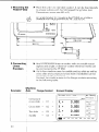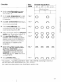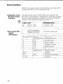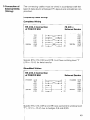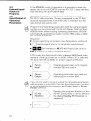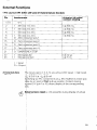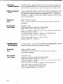
1
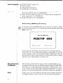
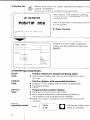
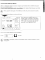
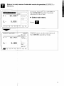
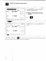
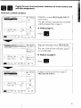
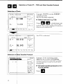
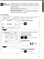
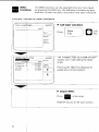
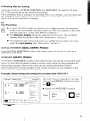
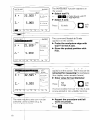
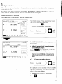
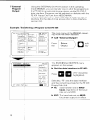
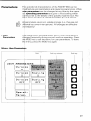
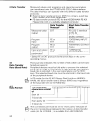
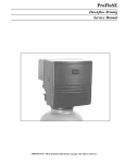
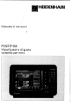
Ilu
HEIDENHAIN
Operating Instructions
POSITIP 850
Programmatile
for Lathes
I
I
Digital Readout
l
l
l
l
Optional
POSITIP 850 Display Unit
Power Cable
Operating Instructions
Certificate of Inspection
Connector, 25-pole. for D-subminiature
socket X41 (EXT)
external functions (Id:Nr. 249154ZY)
l
Data transfer cable, 25-p&
for D-subminiature
socket X31
data output (Id.-Nr. 27454501)
. Angle bracket (Id.-Nr. 258 26101)
l
Selecting
Milling/Turning
As delivered. the POSITIP 850 can be set up for either milling
or turning applications. The following
screen appears after tht
first power-up:
HEIDENHRIN
POSITIP
After press
nently set j
screen dlq
ling functio
Turning” (see
Manufactur
Certificate
r’s
t
I
Note
850
I the fl key, the program for turning
., is not affected by power interruptions).
and th
i cannot be accessed again. Selection of the mi
s then only possible via parameter P99.0 “Millin!
“Parameters”,
section 4.2)
We hereby certify that the above unit is radioshielded
in accordance with the German official register decree 104611984.
The German postal authorities have been notified of the issuance of this unit and have been granted admission for examination of the series regarding compliance with the regulation!
If this unit is incorporated
by the user into a system. then the
complete system must comply with the above regulations.
r
This description
is valid for software
05.
I
Contents
Working
with
the POSITIP 850
For Lathes
Page
1
2~
Controls
and Screen
Displays
3
POSITIP Operating
4
Cross Over Reference
Switch-On
6
Parameters
6
Modes
Marks
7
~
8
Keys For User Guidance
Commissioning
5
Working
Aids For Turning
15
External
Program
Output
~18
External
Program
Input
20
1
Connections
and Controls (Rear Panel)
2
Mounting
3
Connecting
4
Power
5
Switch-On
and Function
6
Optimizing
the Parameters
1
1.1
I,2
User Parameters
Changing User Parameters ~~~
Overview of User Parameters
2
2.1
2.a
2,3
2,4
Operating
Accessing
Configuring
Presetting
Overview
3
3.1
3.2
Tables -~
Display Step, Signal Period and Subdivision
for Linear Encoders
Distance-Coded
Reference Marks
4
4,1,
4.2
Parameter Description
User Parameters Operating Pars.xters
23
24
~
24
Linear Encoders
25
Connection
.25
Check ~~
Parameters _~
the Operating Parameters.
the User Parameters ~
the User Parameters
of Operating Parameters ~~
~
P
26
,29
30
32
.-33
.~~ 33
.35
- 37
38
~
Factor
~~
42
-42
42
-43
43
44
3
Contents1
(c0nt’d.j
Pa3
Data
1
Definition
Interface
2
Pin Layout X3liSignal
3
Connection
4
4.1
4.2
4.3
4.3.1
4.3.2
4.3.3
4.4
4.5
Data Transfer
Data Transfer Rate (Baud Rate)
Data Format
Measured Value Output
Storage via K-232-C
Interface
Storage via External Functions
Sequence of Character Output
External Input/Output
of Programs
Input/Output
of Operating Parameters
External
Functions
of External
Units (Wiring)
2 External Zero Reset
3 storage
I
(Pulse. Contact)
Signal
STOP signal
D-subminiature
I
I
I
I
i
c
I
I
I
!
/
5 EMERGENCY
4
Interface
Description
1 Pin Layout X41 (EXT) (25-p&
4 Zero Crossover
Specificatiors
of the RS-232-C/V.24
socket)
-
I
I
I
Working
with the
POSITIP 850
For Lathes
ThIis part of the Operating Instructions illustrates the most
lm’portant procedures for operation of the POSITIP 850. For
d&ailed explanations
simply call the HELP functions.
~
Sqmbol behind the display value: 0: Diameter display
I: Scaling factor active
I: Oversize (only active with
Distance-To-Go
function)
QO
With these keys you select the tools from Tl to T20 and the
dar interface (FE, EXT)
S$lection
captor
of pocket calculator
Explanation of all operating
an!d error messages
em ~
Fdr paging through
R&n
to the previous
user parameters
stopwatch
modes. current
the individual
menu or
R&urn to the main menu
s+xt
functions,
screens
and taper
screen contents.
2 Switch-Or
!
l.ak
u
Before iklitial switch-on. please read the information
chapter “Installation”.
The power swilch is located on the rear panel
r
)IEIDENHRIN
PO~SITIP 850
in the
After approx. 5 seconds the opening
screen appears and POSITIP conducts
a memory test.
Adjust brightness
on lea‘ panel)
if necessary
(control
b Press any key
1
POSITIP is in the mode of operation
last selected (in this case.
3 POSITIP
BASIC
Mode
EXPERT
Mode
PROGO
Mode
6
O/perating
Modes:
Position display for simple machining
tasks
l
Actual value display with setting and resetting for up to
20 tools
Position display with expanded
functions
l
Distance-To-Go
display with oversize compensation
l
Note/Set function
l
Datum
Programmable
position display
l
20 different programs can be stored
l
Easy programming
with conversational
guidance,
subprograms
and program section repeats
. Input and outpur of programs over the KS-232.C/V.24
interface.
4 Cross Over Reference
Marks
When a reference mark~is crossed, a signal is generated which identifies that position as a machine da&
Crossina over the reference marks r-establishes
the relationshio between axis slide
positions and display va!ues which was last set.
After a power
interruption.
the reference
marks must be crossed
in all axes
T!!b
After crossing the referqnce
marks in all axes:
The main menu appears for the selected mode of operation. The abbreviation REF in the entry line indicates
REF mode. The position data are referenced to the highlighted tool.
If you do not wish referaxe
If NO R!3F is s&&d.
mark evaluation:
positions
and display values will be lost after a power
5 Keys For L/SW Guidance
The HELP function can guide you through the operation of
the POSITIP 850. Think of it as integrated operating instructions. At any time during operation you can call up an explanation of the current screen image by pressing the HELP key,
The HELP function can also tell you how to proceed when an
errm message OCC”lS~
Calling
the (IELP Function
Example: POSITIP is in the main menu
of the EXPERT operating mode.
b Call HELP:
An explanation
TION appears
of ACTUAL POSIon the screen.
A HELP text can consist of several
pages. The current page and the total
number of pages is displayed in the
lower right-hand comer of the screen.
b Page further:
to page forward
to page backward
b Depart
Press
HELP:
.
once again.
m
POSITIP serums to the original
8
screen.
e
Return to majn menu
PROGO).
of selected
mode
of operation
(EXPERT
or
Example: Operating mode EXPERT,
the NOTE/SET
function has been
selected for the X axis
F Select
main
menu:
9
Q
Retlrrn
to previous
work
axeen
POSITIP returns to the previous
Each time yod press the
the main menp of the selected
IO
work
key you jump back by one menu level, until you reach
mode of operation.
Pagin
forward
and backward,
soft kjy assignment.
Selection
-~
of Work
selection
of work
screens
and
Scripens
POSITIP is in the PROGRAM
INPUT
main menu.
The - symbol indicates the currentlyselected page (here. page 1).
t Select
page 2:
-
Display returns to the first page of
PROGRAM
INPUT.
1
00
Selection
Selection
of Tools
(Tl - TZO) and Data Transfer
Protocol
of pools
Example:
POSITIP is in the EXPERT
Tool T20 is selected
Selection
of b ata Transfer
Protocol
Example: In the operating mode
PROGO. the function EXTERNAL
OUTPUT
has been selected. The data
transfer protocol is set for the FE 401:
Display FE
b Set data transfer
e.g. for printer:
12
protocol
to EXT,
User
Parameters
POSlTlPfeatures
non-volatile
parameter storage: the parametejs become effective immediately
upon switch-on. The parameters are divided ,“to Two groups: user parar”eIers
and operating parameters.
U&w parameters are parameters that can be changed during
operation by pressing the MOD key.
Operating parameters concern machine characteristics and
are given a fixed setting. For more information on operating
parameters see Parameters section.
User Parameters
Example: The ACTUAL POSITION
function has been selected.
b Call user parameters:
An overview
of available
parameters
Select desired
column
/
13
The INFO functions can be selected from any menu level
by pressing the INFO key. The following functions are then
available: pocket calculator. stopwatch, and taper calculator.
The TAPER CALCULATOR
explanation
b Depart
of this function.
INFO:
POSITIP returns to the work
14
function
screen.
6 Working
Aids for Tutning
Using the functions ACTUAL POSITION and NOTE/SET, the data for 20 tools
(Tl - 120) can be set on the machine and stored.
If the workpiece
datum changes. for example after a tool change, it can be reset with
the DATUM function. All preset tool data will then automatically
refer lo the new
datum and do not need ylo be changed.
6.1
Tool Presetting
@
b In order that all,tool data are stored in non-volatile
storage, the reference
marks must be,crossed over after switch-on.
REF must appear in the entn/
line (see section 4. “Cross Over Reference Marks”).
b The diameter
tilsplay should be selected for the X axis. The symbol 0
appears after the display value (see “Parameters”,
section 1).
b For machines with compound
axes (e.g. saddle and top slide), you nwst
select the sumldisplay
(see “Parameters”.
section 1).
ACTUAL POSITION
(BbSlC,
In the ACTUAL POSITION
maximum of 20 tools.
NOTE/SET (EXPERT,
EXPERT,
function,
PROGO)
the display value can be set or reset for a
PROGO)
The function NOTE/SET is helpful when determining
tool data by probing the workpiece. In order that the position value is not lost when retracting the workpiece
for
measuring purposes. th$ position value can be stored beforehand (“Note”).
After measurement
of ttJe workpiece,
the measured value can be assigned to the
stored position as the display value (*Set”).
Example:
Determininq
and setting
the tool data with
NOTE/SET
is selected in the operating mode EXPERT (otherwise press
t Select the NOTE/SET
function:
15
The NOTE/SET
the screen.
b Select
function
appears
on
X axis:
The command Scratch in X axis
appears on the screen.
b Probe the workpiece
edge with
tool Tl in the X axis.
the probed position with
The command Enter value for X-axis
appears on the screen. The X axis can be
retractedformeasuring
theworkpiece
(the display value remains frozen).
b Enter value for tool diameter:
m
T2 T
74 T5 76 77 T8 79
The next machine axis can now be
selected o&he screen (e.g. Z,
am). or the~next tool.
The tool position for tool Tl in the X axis
is now stored in non-volatile
memory.
b Repeat the procedure
tools are preset.
b Depart NOTE/SET:
until
all
6.2
Workpiece
Datum
After the workpiece
machining is set.
has been clamped,
the zero point or the datum for workpiece
Tool data Tl to T20 ente;red in ACTUAL
POSITION
or NOTE/SET
ally refer to the new datum and do not need to be changed.
Datum (EXPERT, PROQO)
Example:
Set new datum
with
a preset
then automati
tool
The main menu of the operating
EXPERT
has been selected
(otherwise
press f#
b Select
the Datum
The SET DATUM
the screen,
mode
).
function:
function
b Select preset tool now
for example:
T20:
appears
on
inserted,
p Face the workpiece
for the new
datum, or touch the workpiece
face.
b 0
Enter value
for datum:
The datum IS now stored in non-volatile
memory, All preset tools automatically
refer to the new datum.
t
Depart
SET DATUM
function.
17
7 External
Program
Output
Example:
Using the EXTERNAL OUTPUT function in the operating
mode PROGO. you can transfer one or all of the programs in
the PT 850 to an external storage device via the R-232-C
data interface. Programs can be archived on diskette with the
FE 401 Floppy Disk Unit from HEIDENHAIN.
Printers used with the Pi 850 must have a serial 6232-C
interface (for the data format please refer to Data Interface.
section 4,2).
Trahsferring
a Program
to the FE 401
The main menu of the PROGO
operat-
soft
kev
The EXTERNAL
OUTPUT
appears on the screen,
b Set the data
interface
menu
to FE 401:
Selecting “FE” sets the data interface
and the correct baud rate for the FE 401
Floppy Disk Unit.
t
FE:
Data transfer rate is 9600
baud, regardless of the baud
rate set via MOD.
b EXT: The baud rate set via MOD
for printer output is in effect,
18
Output
a single
b Enter program
progrbm:
number
b m
Output
0
Begin program
all programs:
If there are programs
be overwritten.
Directory
of programs
+iigp
on the diskette
stored
of programg
stored
.#q”
with the same PGM number, they will
in the POSITIP
program
memory:
The ~roaram number as well as the number
pro&am blocks is displayed
u
Directory
Cancel
output
of
on FE diskettes:
Duma
read-in
of the “ronram
dirertnrv
the
data transfer:
b 1 Escape
)
0
Data transfer
is cancelled.
19
8 External
Program
Input
Using the EXTERNAL
INPUT function in the operating mode
PROGO. you can transfer programs from an external storage
device into the PT 850 via the RS-232-C data interface.
Computers used with the PT 850 must have a serial R-232-C
interface (for the data format, please refer to Data Interlace.
section 4.2).
Example:
Loa
mg a Program
P.
from the FE 401
The main menu of the PROGO
ing mode has been selected.
w Call “External
operat-
Input”:
The EXTERNAL
INPUT
appears on the screen.
b Set the data interface
menu
to FE 401:
Selecting “FE” sets the data interface
and the correct baud rate for the FE 401
Floppy Disk Unit.
b FE:
Data transfer rate is 9600
baud, regardless of the baud
rate set via MOD.
b EXT: The baud rate set via MOD
for printer output is in effect.
Enter the program number of the program to be transferred. If necessary. call up
the directory of progrdms on the diskette using the soft key FE 401 PGM Dir (see
“Program Output”).
11,:) 0 poslTlp.
Start transfer
of program
from floppy disk unit to
Commissioning
~
The buffer batteries (th ee A&size 1.5 V batteries) serve as a power supply for the
program memory. Exchange the batteries if the error message EXCHANGE
BUFFER BATTERY
a pears.
P
The unit must remai
switched
erasure of Stored pr&ams.
on during
battery
It is very important that you follow
dhen commissioning
the unit.
do not engage
under power.
or disengage
exchange
to prevent
this sequence
any connectors
of steps
while the unit is
23
2 Mounting
PDSITIP
t e
85 s
b Place the unit in its intended location. It can be fixed laterall)
to a base surface with the M4 tapped fixing holes (see
Dimensions. screw size M4 x 6).
An angle bracket for mounting the PT 850 on a table is
available from HEIDENHAIN (Id,-Nr. 25826101).
3 Connecting~
Linear
Encoders
F Any HEIDENHAIN linear encoders with sinusoidal output
signals and single or distance-coded
reference marks can
be connected to the PT 850.
F Up to four machine axes for saddle and top slide as well as
cross slide and compound
cross slide (if available) can be
connected to the rear panel.
Connect the machine axes to the flange sockets according
to the following table:
Compound
cross slide
24
’
Xl
*
Cross slide
-
X2
-
Top slide
-
x3
-
Saddle
-
x4
-
4 Power
Connection
5 Switch-On
Function
t Check whether there is a protective ground for the power
~ connection. An M5 threaded pin on the rear panel provides
~ an additional connection for protective ground.
w Connect power cable to the power input socket on the rear
panel, and switch on power.
and
Check
Pi!,
~
7he unit is adapted to the machine tool by means of paw
melers. See Parameters section, The unit is delivered with
preset parameters
to facilitate commissioning
(see Pararwters. section Z4).
droceed in the following sequence to commission the
machine:
w Switch on power.
t Adjust desired screen image brightness with control on rear
panel.
t Select desired application (milling or turning). The menu for
application selection appears only once after initial switchon.
‘1 Press any key (except the HELP key).
k Choose BASIC mode of operation (see Working with the
POSITIP 850)~
* Press NO REF soft key. Now you need not cross over the
~ reference marks (ignore error messages).
bf Use the MOD key and code number 95148 to access the
operating parameters (see Parameters. section 2).
Y Optimize operating parameters (see Commissioning,
~ section 61~
b Switch power off and then on again.
Cr Cross over the reference marks (see Working with the
POSITIP 8501,
Error Messages
After the reference marks have been crossed
ghould be no error message in the display.
over there
Ii an error message is displayed, press the HELP key for more
lhformation and then correct the ermr, Switch power off and
then on again.
If several errors occur at once you can display the error mes$ages one after the other by repeatedly pressing the CE key.
25
6 Optimizing the
Parameters ~
You can adapt the functions of the POSITIP to the machine tool
by optimizing the parameters. Proceed in the sequence given
in the following
checklist. Write the axis designations
of the
connected machine axes onto the checklist, and check off
each step when you have completed it.
Parameters which must be frequently changed during
machine operation are entered as user parameters
(see
Parameters section).
26
Checklist
& Are the machine
ax&
to the correct encod@r
(see section 3)
assigned
inputs?
X and Z
Change
P 50.”
0
0
b The axis combinatibn
Separate or
Sum can be set in p&meter
P 30.”
or as a user paramettw
P 30.”
0
0
b Check axis definitioh.
Set
connected encoder i$puts to linear,
unconnected
inputs to off.
P 48.”
0000
b Enter parameter value for reference
marks (see Parameters. table 3.2).
P 45.”
F Set counting
direct@
of the
machine axes. Increasing positive
display values must correspond to
the positive direction of machine
axis traverse in relation to the
workpiece.
P 40:
0000
0000
t Approach a datum 00 the workpiece and set the di$play value
(ACTUAL
POSITIO@J function).
Then move individual: axes and
compare the actually traversed
distance with the v&e
displayed
on the POSITIP.
P41~”
P 42:
0000
b Check diwlav
(see Para&&
P 43.’
0000
b Do the axis designations
match the machine aws?
if necessary.
steo
t&e
3.1).
* The asterisk ,,*” signifies parameters which are specified according
number behind the decimal point (e.g. 4.1, 4.2 etc.).
(For parameter descriptions see Parameters, section 1,4).
to axis by a
27
Parameters
Ti$e operational characteristics
of the POSITIP 850 can be
Modified via user parameters and operating parameters. While
u er parameters
can be changed at any time by the operas
t ,’ I operating
parameters
are given a fixed setting which
c#responds
to the details of the specific machine tool. The
p$rameters are given a standard presetting in the factory,
in non-volatile
interruptions).
1 User
Parameters
Menu:
storage (i.e.. they are not
All changes are effective
Uber parameters are parameters which must be entered or
changed frequently during normal machine operation. Press
ttje MOD key to call the menu for user parameters. To leave
ttje menu, press the MOD key again.
User Param&@
29
1.1
Changing
H Changing
with Soft Keys
Soft keys can be used to change from radius to diameter
display, to switch the axis combination
from separate to
sum. and to select scaling factor ON or OFF and oversize
ON or OFF.
USW
Parameters
Example:
Radius
or Diameter
Display
Switch to diameter
display
The “W symbol for
diameter appears
next to the display
value.
30
@ Changing
User Parameters
This concerns
Example:
Via Numerical
the input of scaling factors
Input
and oversizes
Oversize
n
Enter numerical value.
for example 10
) VI
Oversize
is entered
31
1.2
Overview
of
USW
Parameters
Selection
via hnO0 key
Function
Axis
Radius/Diameter
X
T
Change
Input
Soft key
Separate/Sum
Soft key
Scaling Factor
Numerical
Scaling Factor ON/OFF
input
0.100000
9.999999
to
input
0 to f 199.999
Soft key
Oversize
Numerical
Oversize ON/OFF
a descrlptlons
Soft key
of user parameters
see section 4,l)
If “Diametef
or “Scaling Factor ON” have been selected,
symbols appear behind the display value:
0: Diam&er display
!: Scaling factor active
!: Oversize active (only with the Distance-To-Go
32
function).
the following
2 Operating
Parameters
There are three groups of operating parameters:
4 P 1 .I to PI 2.0 - configuration
of the user parameters
R P21.1 to P320
presetting of the user parameters
* P40.1 to P99.0
operating parameters for machine interface
jhese settings are normally made only once during commissioning and then remain fixed.
operating parameters can only be selected through code
n!umber 95148 and should not be changed by the machine
operator. We recommend
that you keep a written copy of the
ehtry values for the operating parameters or store them on an
e~tetnal data medium.
2.1
Accessing
Operating
Parameters
the
-.
Opera
Param.
1
Enter code
number 95148
I
b
I
Access to operating
parameters (for selection of operating parameters. see next page)
33
Selecting
the
Operating
Parameters
Select desired operating parameter
with veltical soft arrow keys.
W Selection
via GOT0
Press soft key (the last selected
parameter number will appear in the
input line).
Enter desired
parameter
Select operating
34
number.
parameter.
Changing
Operating
Parameters
? Changing
4al value
operating
parameters
by entering
a numeri-
Example: P 31.1
Enter numerical value (e.g. 1).
q Changing operating
Wt arrow key
parameters
with the horizontal
The frame in the parameter line indicates
the current parameter entry value. Press
the soft key to bring the next parameter
entry value into the frame.
Pressing the soft key Enter transfers the
entry value: the next parameter is then
displayed,
2.2
Configuring
the User
Parameters
qressing the MOD key calls the user parameters to the display,
Tihese parameters are located in soft-key fields in a certain
airrangement
of field positions. The field positions are indicated
lily the numbers in the illustration below (factory presettina as
id appears after switch-on).
The field position of any user parameter can be changed by
Weans of the operating parameters P 1.1 to P 12.0. (Exception:
fibId position 15 operating parameters.)
By entering a positibn of 0. the selected user parameter can be locked from
access.
35
:
:;
ii.i/
:i
,B
Changing the ~
Field Position
W First you must gain access to the operating parameters
using the procedure described above in section 2.1. Then
select the desired soft-key field.
Example:
You wish to transfer the parameter
position 3.
Original
in field position
4 to field
Display
Radius
X
Radius
Z
Seprt
X
Seprt
Z
Procedure
b Select the parameter in field position 4 (factory preset to
P 10.31.
t Enter the new field position (position 3) with numeric keypad and press the soft key Enter.
Pressing the
meters.
New Display
36
key recalls the menu for the user para-
The overwritten
parameter
into the table as follows:
(Sepri X) can be reentered
e Repeat procedure for access to operating parameters and
select the overwritten
parameter (P 10.1 Seprt X). This parameter has assumed the Position: 0.
Pi,
Access to user parameters via the MOD key can be locked by
$ntering Position: 0.
hte: Locked user parameters can only be changed via the
operating parameters P21 .I to P32.0.
If you wish to transfer the locked user parameter (P 10.1) to the
vacant field position 4. enter field position 4 for this parameter.
2.3
Presetting
the User
Parameters
User parameters can also be set with the operating parameters (P21.1 to P32.01, This makes it possible to change locked
user parameters. Changing these parameters is effective
regardless of whether they are changed in the “User Parame~
ters” menu or the “Operating Parameters” menu.
37
2.4
Overview
Operating
of
Pargmeters
Function
1
Radius/Diameter
Xl/X2
Radius/Diameter
X3/X4
Scaling Factor Xl/X2
Scaling Factod X3/X4
Scaling Factor ON
Baud Rate RS-232-C
Line Feed FG232-C
Mode of Operation
Separate/Sum
Xl/X2
Parameter
P 1.1
separate/sum
x3/x4
Oversize Xl/X2
Oversize X3/x4
Oversize ON ~
Radius/Diam@er
Xl/X2
Radius/Diameter
X3/X4
Scaling Facto? Xl/X2
Scaling Factor X3/X4
P 10.3
Pll.1
P11.3
P 12.0
P21.1
P 21.3
P 23,l
P 23.3
Scaling Factor ON
Baud Rate RS-232-C
P 24.0
P 27.0
Line Feed RS~232-C
separate/sum
Xl/X2
Separate/Sum
x3/x4
Oversire Xl/X2
P 1.3
P3.1
P 3.3
P 4.0
P 7.0
P 8.0
P 9.0
P 10.1
Oversize
X3/X4
P 28.0
P 30.1
P 30.3
P31~1
P31.3
Oversize
ON
P 32.0
38
”
Axis*
X
Z
X
z
i
.
Entry”’
1
2
6
7
8
0
0
9
X
Z
X
Z
X
Z
X
Z
X
Z
X
Z
f
0
3
4
11
12
13
Radius,
Diameter
1.000000
(0.100000
9.999999)
to
off. on
9.600 1110.
150. 30b. 600,
1200,2400,
4800.9600.
19200,
38400 baud)
1 (0 to 99)
Separate,
Sum
Separate,
Sum
0.000
(0 to
* 199.999)
off. on
Operating
Parameters
(cont’d.)
[
Counting
Direction
Xl
Counting
Direction
X2’
Counting
Direction
X3
Linear Subdivision
X2
Linear Subdivision
X3
Linear Subdivision
X4
Distance
Coding X2
Distance
Coding X3
*
For the sake of simplicity. the axis designations
are assumed to be those set in
palametel P50.’ (X14X2 =X-axes,
x3/x4 = Z-axes).
Xl, X2, X3, X4 are thp corresponding
designations
of the encoder inputs (see rear
panel).
** Factory presettings a:re indicated in bold type.
39
Operating
Parameters
Parameter
Function
Monitoring
(cont.‘d.)
P 46.1
Xl
X0
I
Entry’
t 99999
Axis*
Monitoring
X2
P 46,2
X
Monitoring
X3
P 46.3
ZO
Monitoring
X4
P 46.4
X0
Linear Correotion
Xl
P47.1
Linear Corredtion
X2
P 47.2
X
Linear Correction
X3
P 47,3
ZO
Linear Correotion
X4
P 47.4
Axis Definition
Xl
P48.1
Z
X0
Axis Definitiin
X2
P 48,2
X
Axis Definitiqn
X3
P 48.3
ZO
Axis Definition
X4
P 48.4
Axis Designation
X1/X2-
P50.1
Axis DesigrWtion
X3/X4
P 50.3
P 52.0
zero Range Xl
P 56.1
Zero Range x2
P 56.2
Zero Range k3
P 56.3
ZO
Zero Range X4
P 56.4
Z
40
0to
pm/m
I
off, linear
H
I
Dialog Language
off, on
I
2 languages
be selecred
can
isee
Operating
Paramete$
(cont’d.)
Function
~
Display Freeze
Parameter
P 57.0
Axis*
I
Modd
Delay
Positioning
Aid
Counter Application
(For description
*
1 P 58.0
~
P 59.0
1
P 60.0
P 99.0
~
actu
val
stopped
!
Distance-To-Go
I
1 graphic,
15
5 to 98 (min.)
99 = no protective
standby mode
normal,
inverse
milling. turning
see se#tion 4.2)
For the sake of sim ‘Ii&y. the axis designations
are assumed to be those set in
parameter P50.” (X ix2 = x-axes, x3/x4 = Z-axes).
Xl, X2. X3. X4 are tIr, e corresponding
designations
of the encoder inputs (see rear
panel).
** Factory presettings
Bre indicated
in bold type.
*:
/:
1;
I
41
3 Tables
3.1
Display StewSignal
Signal
Perio
Display
Sta
0.00005
0.0001
Period
in.
in.
Reference
80
40
I 100
T
Max. Traverse
the Datum
Depends
LS IOIC
IOmm
LS
LS
LS
LS
LS
20 mm
I
4Ovm
IOOpm
200pm
Factor
-
20 mm
for Recovery
on position
10 mm (grating
20 mm (grating
42
20pm
Encoders
-
-
Marks
No distance-coded
reference marks
LID 351 C
for Linear
Subdivision
Unear
107c
303c
403c
404c
603C
Factor
IOpm
4w
mm/0.000002
mm/0.000005
3.2
Distance-Coded
and Subdivision
of
of the encoder
Parameter
P 45:
= none
P 45.” = 1000
period
period
10 pm)
20 urn)
P45.‘=2000
4 Parameter
Description
4.1
User Parameters
Radius/
Diameter
with this parameter you can select radius or diameter display.
It you select diameter, the symbol “0’ will appear behind the
d:isplay value.
Separate/Sum
qith the parameter Separate/Sum
it is possible to display
s&rately
or as a sum the position values of saddle and top
slide as well as of cross slide and compound cross slide.
Scaling
The scaling factor changes the display value and thus either
Factor
reduces (input 0,l to 0.999999)
or increases (input 1.000001
to 9.999999)
the dimensions of the workpiece
to be
n?achined. The scaling factor can be entered either for the X
and Z axes together. or separately for each axis.
If;the scaling factor is entered
effective for all axes
with the soft key Set for all, it is
Scaling Factor
OFF/ON
BV selecting scaling factor OFF. all scaling factors are deactiv&d. When scaling factor ON is selected. the symbol “1”
appears behind the display value,
Oversize
Ah oversize entered (0 to & 199.999 mm) is applied to the
nominal position value entered in the Distance-To-Go
function.
Ah oversize can be entered separately for each axis.
O&r%?
is only effective
with the Distance-To-Go
function.
yhen working with POSITIP programs. an oversize should
alkeady be taken into account when entering the nominal posttimns. Using the Oversize user parameter with programs is not
r&ommended.
since this parameter is continually active when
Okrsize
ON is selected (modally effective).
Ainegative
Oversize
OFF/ON
Special Case:
Mode of
Operation
oversize
reduces
the contour.
Jhen Oversize OFF is selected, all oversizes become inactive.
When oversize ON is selected. the symbol “1” appears behind
the display value.
This parameter is not configured as a user parameter in the
f&tory presetting. With the Mode of Operation parameter you
can choose among the BASIC, EXPERT and PROGO modes
of operation via the MOD key without switching the unit off.
Ttje user pamneter Mode of Operation is only active if operaIing parameter P 9.0 is configured as a user parameter (see
section 4.2).
43
4.2
Operating
Parameters
dIdA
u
P
In the following
description, axis-specific
parameters
are
lndlcated by a parameter number with decimal point and
asterisk (example: P 1 .*I.
The asterisk signifies the axis-specific
designation
decimal point (e.g. P 1 .*-P 1 .I or P 1.3 etc.).
Parameters which are not axis-specific
behind the decimal point (e.g. P 7.0).
Pl.”
to P 12.0
~
Special Case:
P 9.0
Mode of
Operation
after the
are indicated
by a 0
The YJser Parameters” menu is configured
by entering posltions in operating parameters P I.* to P 12.0. The user parameters can be configured
in any desired sequence within the
positions 1-14. Position: 0 locks the respective parameter frorr
access via the MOD key (see section 2.2).
In order to prevent an inexperienced
operator from making
mistakes, the mode selection (BASIC, EXPERT, PROGO)
should be made accessible immediately after switch-on and
then remain unchangeable
during machine operation. Parameter P 9.0 is therefore not active as a user parameter (position = 0). If parameter P 9.0 is configured as a user paramete
the operating mode can also be selected during machlnlng.
If you wish parameter P 9.0 to be a user parameter, a vacant
position should be chosen (such as position = 14).
User parameters can also be set in the operating parameters
(P 21.1 to P 32.0). making it possible to change even locked
user parameters. Changing these parameters is effective
regardless of whether they are changed in the “User Parameters” or in the ‘Operating Parameters- menu. (For description,
see section 4.1.)
P21.1
to P 32.0
P40.’
Counting
P 41:
Signal
44
Dirktion
Period!
With parameter P 40~” you can set the counting
arately for each axis.
The signal periods of the connected
entered in parameter P 41.‘.
direction
linear encoders
are
sep~
P 43.”
Linear
Subdivision
The subdivision factor is entered in parameter P 43.“. The subdiivision factor determines the display step and depends on the
setting of the signal period (see Table 3.1).
P 45.”
Distance
Coding
Parameter P 45.” defines whether the display unit is to evaluate signals from encoders with single or with distance-coded
r$ference marks. For encoders with single reference marks.
select none. For distance-coded
reference marks, the entry
value depends on the encoder model (see Table 3.3).
P 46.’
Monitoring
yth parameter P 46.” on, the corresponding
encoder
qgnal is checked for the followlng errors:
ai excessive traversing speed
*I cable break
0: measuring signal error
These errors are then displayed on the screen.
P 47.*
Linear Correction
Machine errors can be measured with the aid of a comparator
rrjxzasuring system (e.g. VM 101 from HEIDENHAIN). These
errors can be entered in parameter
P 47.” as a linear correct
tibn factor in parts per million (ppm) measuring length.
ELanpIe:
Measuring length
Value actually measured
(e.g. via VM 101)
Difference
Conversion
-124 pm
0.620 m
correction
to 1 m measuring
input
620 mm
619.876
=-124pm
mm
length
- 200 vrn
factor
- 200 pm
inear Compensation
!Lengthening”
the encoder
Perameter
P47: 0 to + 99999
[urn/m]
Shortening”
P47: 0 to - 99999
[pm/m]
the encoder
input
Range
45
P 48.”
Axis DefinitioD
Parameter
P 48.” defines whether
For unused
encoder
the axis input is inhibited.
inputs enter off in paramerer
P 48.‘.
P 50.”
Axis Designation
Parameter P 50,’ defines the assignment of axis names to
Inputs.
Possible settings: A, B, C, U, V, W, X, Y, Z.
P52.0
Dialog
The dialog language can be chosen from two available
languages. Which two languages are available depends
program number:
Language
Program
46
No.
Languages
246060..
246061 ,.
246062,.
German
French
Dutch
English
English
English
246063..
246064..
246065,.
246066..
246 067..
Italian
Spanish
Danish
Swedish
Finnish
English
English
English
English
English
246068..
246069..
Turkish
German
English
French
246070..
246071.,
246072..
Dutch
Magyar
Czech
French
English
English
246073..
English
French
on the
P 56.”
Zero Range
PBrameter P 56.” defines a range around display value “zero”
i which a zero crossover signal will be generated (see External
Anctions).
t+ut range: 0 to 99.999 mm.
P 57.0
Display
The current measured value is stored and output over the
R/%232-C data interface with every storage procedure (CRL.
p(~lse, contact). The display on the sxeen
can be set with
pbrameter P 57.0:
the display is not stopped during a storage
OF:
signal
c@ncmt: the display is stopped only for the duration of the
storage signal
I
stppped: the display is stopped. but is updated by every
storage signal
Freeze
P 56.0
Distance-To-Go
Mode
ini the distance-to-go
&yed instead of the
gtaphic:
graphic
aqtual value: display
beneath
function. the actual value can be disgraphic positioning aid.
positioning aid
of the absolute position in small type
the distance-to-go
display.
P 59.0
Sleep Delay
Pairameter P 59.0 allows input of a delay
pjotective standby mode. If no keys are
movements take place for the length of
d lay time, the screen image is reversed.
b $ ring.
5 I- 98: delay time in minutes
~ 99: no protective standby mode.
P 60.0
Positioning
Aid
\hlith parameter P 60.0, the direction of movement of the
g+phic posirioning aid (see P 58.0) can be changed to adapt
it 10 tool movement on the Z axis of lathes.
P 99.0
counter
Application
T$s parameter
tl$ning.
time (in minutes) for
pressed and no axis
time entered as the
This prevents screen
sets up the POSITIP 850 either for milling or
47
Data Interface
POSITIP is equipped
standard KS-232-C
1 Definition
of the
RS-232-C/W.24
Interface
Logic
Description
48
X31
according
to EIA
The data transfer code is ASCII with even parity bit.The
G-232-C
data interface is designed for serial data transfer;
devices with parallel data interfaces cannot be connected.
Levels forTXD and RXD (negative level for ‘I”):
‘1”:
-0”:
2 Pin
Signa,Layout
with a data interface
(CCITTstandardV.24).
)
Level
-3vto-15V
+3vto+15v
1-1
Working
Level
I -5vto-15V
+5vto+15v
RS-232-WV.24
port
3 Connection
External
(Wiring)
of
Units
The connecting cables must be wired in accordanw
type of data device employed. Pin layouts are SOI
Ftandard.
Frequently
Complete
used wiring:
Wiring
Connection
of POSITIP 850
M-232-C
FE 401 or
External Device
Signals FITS. CTS, DSR and DTR must have working
rr5 to -15 V) for data transfer.
$implified
with the
level ‘1”
Wiring
Connection
~of POSITIP 850
~ RS-232-C
External
Device
Qignals RTS. CTS, DSR and DTR have permanent working
“b’ (-5 V to -15 V) due to bridges 4/5 and 6/20.
level
49
4 Data Transfer
Measured values. part programs and operating parameters
can transferred over the PT 850’s RS-232-C data interface.
The data interface can operate with two different data transfer
protocols:
b External data transfer protocol (EXT) for printers, punching
units, readers and other peripherals.
b FE data transfer protocol (FE) for the HEIDENHAIN FE 401
Floppv Disk Unit or a suitablv adapted computer.
Data Transfer
Protocol”
Start
With
EXT
RS-232-C interface
(CTRL 6)
Ext. functions
(pulse, contact)
Program
Input
FE or
EXT
‘EXTERNAL
men,,
INPUV
Program
output
FE or
EXT
“EXTERNAL
OUTPUT-
“XC!“”
Input and output
of operating
pXT”&E
FE or
EXT
“OPERATING
PARAMETERS”
Measured
output
value
* Select FE or EXT protocol
sponding menus.
4.1
Data Transfer
Rate (Baud Rate)
via the arrow
Data Transfer
menu
keys in the cove.
The baud rate indicates the number of bits which can be Vansferred per second.
Peripheral devices must be fully able to process the selected
baud rate in order to avoid errors in data transfer. The desired
baud rate is selected in the user parameters (via the MOD
key). The selected baud rate must be identical to the baud rate
of the peripheral device.
In FE mode (for the FE 401 Floppy Disk Unit from HEIDENHAIN). the data transfer rate is always 9600 baud regardless
of the baud rate set via the MOD key.
4.2
Data Format
The individual
characters
consist
of
~s~D~DID/DIDIDIDIPISISI
The connected unit must be set to “even parity- because of
the error monitoring employed in this output. A data transfer
cable (Id.-Nr. 242869.
.) is available from HEIDENHAIN.
50
4.3
Measured
Value Output
The current display value can be transferred over the
PS-232-C data interface to peripheral equipment such as a
printer. After an external storage command, the measured
value is output (for a maximum of 4 axes) through an internal
buffer. The storage signal can be generated via the RS-232-C
interface or via the “external functions”.
4.3.1
Storage via
RS-232-C
Interface
When the control character CTRL 6 (= STX) is transmitted, a
storage signal is generated and the measured value is transmitted over the TXD output of the K-232-C
data interface.
The duration of data transfer depends on the selected baud
late. the number of axes and the number of line feeds.
t, 5 0,5 ms
t2(30ms
t,Z
Oms
t =187xM+(Lxll)
D
Baud rate
’
L = Numer of line feeds
M = Number of axes
Interruption
of Data Transfer
?he receiving device can interrupt and restart data transfer by
r Start/stop via the RXD input of the data interface
DC3 =X OFF = CTRL S: interrupt data transfer
DC1 =X ON = CTRL Q: resume data transfer
t Control line CTS
After the stop signal CTS or the stop character DC3 has been
received, no more than two additional characters can be output.
51
4.3.2
Storage via
External Functions
Contact closing against 0 V on the 25-p&
D-subminiature
socket X41 causes a storage signal to be generated and the
measured value to be transmitted over the TXD output of
the RS-232-C interface. The time required for data transfer
depends on the selected baud rate. the number of axes. the
number of line feeds and the type of storage signal (pulse or
contacti.
t, 5 0.8 us
Delay
actual
Delay
actual
Input
Input
tl c 4.5 ms
t, 2 1.2 ms
t,Z7ms
t,zZ30ms
t32
Oms
between storage signal and
storage (pulse)
between storage signal and
storage (contact)
signal (pulse)
signal (contact)
tD=187xM+(Lxll)s
Baud rate
L = Number
M = Number
of line feeds
of axes
The transit time of the encoder signals from input to the intema
buffer is approximately
4 ps. The measured value which is
stored is therefore the value which existed approximately
4 vs
prior to the time point of storage.
(See also External Functions).
52
4.3.3
Sequence
Character
of
Output
Sequence
of Character
output
Depending on the axis definition, the characters for measured
yalue output are generated in the following order:
Iz,I’
Output
=
+
(example
5r
8
4
for linear
1
2
axis)
9
0
7
R
CR)
<LF,
Axis designation2 places for
axis designation
o = top slide
s = sum display
or blank space
Places before decimal
Decimal
point (2 to 7)
point -
Places after decimal
moint (1 to 6)
Unit of measure
(blank space for mm.“’ for inch)
R = radius *
D = diameter *
Carriage return
Line feed (see user p$rameter
“Line Feeds’)
* In the Distance-To-Go
function,
l for radius display a lowercase
r is output
l for diameter
display a lowercase d is output
Q.4
No display values are produced if the linear encoder is defer&
In this case.
question marks (?) are generated for the algebraic sign and display value.
53
4.4
External
Input/
Output Of
Programs
4.5
Input/Output
Operating
Parameters
In the PROGO mode of operation. it is possible
grams into or out of POSITIP over the K-232-C
(see Working with the POSITIP 850).
Of
to read prodata interface
Operating parameters can be input and output over the
RS-232-C data interface. Printers connected to the PT 850
must be equipped with a serial RS-232-C interface (for the
data format see section 4,2).
Programs and operating parameters with the same program
number can be stored with the FE 401 Floppy Disk Unit from
HEIDENHAIN. When loading operating parameters. POSITIP
automatically
generates program number 850 unless a different number is entered.
sequence:
b Access
b 0
operating
parameters
(see Parameters.
Select page 2 (menu for parameter
section 2).
input/output).
et interface tc~ FE (FE 401 Floppy Disk Unit) 01
4m
EXT (for printer or other peripheral device).
In FE mode, the data transfer rate is always 9600 baud, independent of the baud rate set via MOD. When EXT is selected.
the baud rate set via MOD for printer output is effective.
Operating parameters with program
number 850 are read in.
Operating parameters
with program number
are read out
850.
If you do not wish to input or output the operating parameters
with program number 850. then the desired program number
must be entered before pressing the Param. Input or Param.
Output soft keys,
Displays the program directory of the
FE 401. During read-in of the directory,
the dialog Reading FE Directory: is
ä
54
Escape
Data transfer
IS terminated
External
Functil
‘ns
1 Pin Layout
X41 (EX
) (25-p&
) Pin
Assignmel
Ec
1110
I
D-Subminiature
Socket)
t
Duration
contact
ov
2
I
Set axi:
tZ100ms
3
4
I
Set axi:
tZ100ms
I
set axk
t>=lOOms
t>lOOms
T
I
Set axi:
0
Zero CT
0
Zero cr
t 0
k
of pulse/
closing
zero CT
0
zero or
21
0
EMERC
22
I
storage
t21.2ps
23
I
storage
tz7ms
I = Input
0 = output
2 External
Reset
Zero
ie inputs (pins 2. 3. 4. 5) are active LOW (open = high level).
I >H2 3.9 v max. 15 V)
I
Nitching via TTL components
(e.g. SN 74LSXX) is made posble by an internal 1 kR pull-up resistor. Contact closing
jainst 0 V (pin 1 or 10) clears display of the corresponding
eternal
xition.
zera reset is only possible
during display of actual
1
55
I
3 storage
(Pulse, Contact)
4 Zero crossover
Signal
Contact closing against 0 V (pin 1 or IO) causes a storage signal to be generated and a measured value to be output over
the KS-232-C data interface (see Data Interface. section 4.3).
A zero crossover signal is produced when the display value of
the corresponding
axis is zt?ro. A zero recognition range (0 to
99.999 mm) can be entered in parameter P 56.“. If the zero
recognition
range is moved over quickly, signal duration is approximately
180 ms.
Technical
Data
Open-collector
Zero crossover
inhibited).
Permissible
Load Types
Resistive load
Inductive load only with quenching diode
High level output voltage UoH s 32 V
(32 V = absolute maximum value of the voltage applied
external resistor or relay)
Low level output voltage UoL 5 0.4 V at loL 5 100 mA
Low level output current loL 5 100 mA
(100 mA = absolute maximum value)
Signal triggering delay t,, = 60 + 20 ms
Signal duration t, = 180 ms
output
signal active HIGH (open-collector
transistor
5 EMERGENCY
STOP Signal
If a critical error occurs within POSITIP. an EMERGENCY
signal is sent over an open-collector
output.
Technical
Data
Open-coilector
output
EMERGENCY STOP signal active HIGH (open-collector
transistor inhibited).
Permissible
Load Types
Resistive load
Inductive load only with quenching diode
High level output voltage UUH 5 32 V
(32 V = absolute maximum value of the voltage applied
external resistor or relay)
Low level output voltage UoL 5 0.4 V at IoL 5 100 mA
Low level output current In, 5 100 mA
(100 mA = absolute maximum value)
Signal triggering d&Y t,, 5 50 ms
56
over
STOP
over
57
Specifications
Mechanical
POSITIP
850 For Lathes
Dpta
Housing
Tabletop model, sheet metal chassis:
Dimensions (W x H x D) 420 mm x 298 mm x 330 mm
(16.5 in. x 11.7 in. x 13.0 in.)
Weight
Approx.
Operating
Temperature
storage
Temperature
0 to 45O C (32 to 113O F)
Visual
Power
- 30 to 70° C (- 22 to 158O F)
Display
Electrical
II,7 kg (25.7 lb)
12.inch
monochrome
CRT
Dat
Supply
Primary-clocked
variable-voltage
(- 15% to + 10%)
Line frequency 48 Hz to 62 Hz
power
supply 100 V ~ 240 V
Power
Consumption
Approx,
Encoder
For all HEIDENHAIN linear encoders with sinusoidal
signals, also with distance-coded
reference marks
7 to 16 PA,,
Inputs
Signal amplitudes
Permissible input
frequency
Data Interface
58
31 W
scanning
Max. 100 kHr
RS-232-ClV.24.
for measured values. programs
operating parameters
110/150/300/600/1200/2400/4800/9600/19200/38400
and
baud
Features
I
AX.%
~4axes with the
idesignations:
A.B.C.U.V,W,X,YorZ
X, and X = Xs
@m display:
ZoandZ=Zs
J(SFPParameters, table 3~1)
Display Step/
Signal Period
~BASIC.EXPERT, PROGO
Modes of
Operation
Program
I
Memory
Tool Memory
Reference
Evaluation
Functions
Mark
50 different programs or 2000 program blocks
Storage of data for 20 tools in non-volatile memory
For linear encoders with distance-coded reference marks or
with one or more reference marks. After a power interruption
i he relatIonshIp
.’
‘, between the
,. encoder position and the display
i/alue IS lost: this relatIonshIp IS quickly and easily re-estabished by crossing the reference marks.
Distance-To-Go display (traversing to display value 0)
Note/Set (for determining tool data)
Datum
: Multipass cycle
4 Radius/Diameter display in 4 axes
Oversize in 4 axes (0 tot 199.999 mm)
Linear machine error compensation
Storage command
Signal output with display value of zero
(zero recognition range: f 99.999 mm)
two languages can be selected (see Parameters, section 4.2)
59
Dimensions
mm/inch
Front
Rear
60
61
DR. JOHANNES
HEIDENHAIN
GmbH
Dr.-Johannes-Heidenhain-StraRe
5
D-8225Traunreut.
Deutschland
7.47 (08669)
31-O
M(O8669)
5061
ST Service
(08669)
31-1272
S’ TNC-Smite
108669)
31-1446
m(O8669)
9899