1
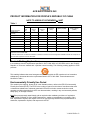
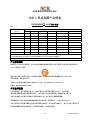
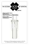
OWNER_____________________________________
VESSEL_____________________________________
RADIO CALL SIGN ____________________________
SERIAL NUMBER _____________________________
Product Support Manual
PathFinder™3
Search and Rescue Transponder
(SART)
Product No. 2714
FCC ID. B66ACR-SART-PF-3
Y1-03-0170
Rev. C
ACR Electronics, Inc.
5757 Ravenswood Road
Fort Lauderdale, FL 33312
Tel : +1 (954) 981-3333
Fax: +1 (954) 983-5087
www.acrelectronics.com
Email: [email protected]
* * * WARNING * * *
THIS TRANSMITTER IS AUTHORIZED FOR USE
ONLY DURING SITUATIONS OF GRAVE
AND IMMINENT DANGER
DELIBERATE MISUSE MAY INCUR A SEVERE PENALTY
Magnet Safe Distance
1 m (3.3 ft)
Stereo Speaker Safe Distance
1 m (3.3 ft)
Keep this beacon a safe distance
away from all magnetic sources
Keep this beacon a safe distance
away from all stereo speakers
IF YOU HAVE ANY TROUBLE
WITH YOUR PRODUCT,
DO NOT RETURN IT TO THE STORE!
CALL ACR ELECTRONICS AT
1 (954) 981-3333. WE WILL HELP YOU
RESOLVE ANY PROBLEMS YOU MAY BE
EXPERIENCING. MANY QUESTIONS CAN
BE ANSWERED OVER THE PHONE.
LIMITED WARRANTY
This product is warranted against factory defect in material and workmanship for a period of one year
from date of purchase or receipt as a gift. During the warranty period ACR Electronics, Inc. will repair
or, at its option, replace at no cost to you for labor, materials or return transportation, provided you
obtain a Return Authorization from ACR Electronics, Inc., 5757 Ravenswood Road, Ft. Lauderdale, FL
33312-6645. To obtain a Return Authorization, call our Customer Service Department at (800) 4320227. This warranty does not apply if the product has been damaged by accident or misuse, or as a
result of service or modification other than by the factory. Except as otherwise expressly stated, the
COMPANY MAKES NO REPRESENTATION OR WARRANTY OF ANY KIND, EXPRESS OR IMPLIED, AS
TO MERCHANTABILITY, FITNESS FOR A PARTICULAR PURPOSE, OR ANY OTHER MATTER WITH
RESPECT TO THIS PRODUCT. The Company shall not be liable for consequential or special damages.
In order to place the warranty in effect, the accompanying registration card must be returned to us
within ten days of purchase.
2
Y1-03-0170 Rev. C
Foreword
Congratulations and thank you for purchasing the ACR PathFinderTM3 Search and Rescue Transponder
(SART). The combination of computer-aided design, high quality raw materials and quality-controlled
manufacturing produce a superior product. The Test Facility at ACR can reproduce some of the harshest
environmental conditions known to man. This assures that the products we produce can stand up to the
rigors found in a marine environment. With proper care and maintenance, your SART will be in service for
years to come.
ACR is proud to be certified to the ISO 9001:2000, the International Standard for Quality.
This manual provides installation, operation and maintenance instructions for the PathFinderTM3 SART,
hereinafter referred to as the SART. This manual also describes the characteristics and details of the
SART system. This SART has been tested and approved to IEC 1097-1 standards and meets IMO RES
A.802(19). This device complies with the GMDSS provisions of Part 80 of the FCC rules and meets EC
Council Directive 96/98/EC for ship wheel approval.
Table of Contents
SECTION 1 – INTRODUCTION ...................................................................................... 4
SECTION 2 – INSTALLATION ....................................................................................... 5
VESSEL NAME ........................................................................................................................................ 5
VESSEL MOUNTING ............................................................................................................................... 5
SECTION 3 – LIFE RAFT STOWAGE AND MOUNTING .............................................. 7
POLE MOUNTED SART.......................................................................................................................... 7
HANGING SART ...................................................................................................................................... 7
SECTION 4 – ACTIVATION ........................................................................................... 8
SECTION 5 – TESTING .................................................................................................. 8
SECTION 6 – SERVICING.............................................................................................. 9
SECTION 7 – TECHNICAL SPECIFICATIONS............................................................ 10
SECTION 8 – DECLARATION OF CONFORMITY ...................................................... 11
Approved for GMDSS use
WARNING: Contains Lithium Battery
To avoid possible fire, explosion, leakage or burn hazard, do not open, recharge,
disassemble or heat SART above +70°C (+158°F) or incinerate.
This product contains lithium in the form of a battery. Shipping of hazardous
materials requires special handling and documentation. MSDS sheets along with
shipping
information
can
be
found
on
our
website
at
http://www.acrelectronics.com/hazmat/default.htm.
3
Y1-03-0170 Rev. C
SECTION 1 – INTRODUCTION
The SART is a Search and Rescue Transponder that provides location information to search radars
operating in the X-band (9.2 – 9.5 GHz). Once activated, the SART detects radar signals from the search
craft and sends a series of response pulses. Twelve equally spaced arcs indicate the direction to the SART.
The International Maritime Organization (IMO) requires all vessels of more than 300 gross registered
tonnage (GRT) to carry at least one SART and vessels 500 GRT and over must carry at least two SARTs,
while Roll-On, Roll-Off Ferries are required to carry one SART for every four survival crafts.
To achieve the maximum useful range, the SART must be mounted at least 3.3 feet (1 meter) above sea
level. Increasing the height of the SART antenna will increase the range. For example, lashing the
SART to the top of a pole or an oar in the survival craft will increase the height and thus the range.
To activate your SART in times of emergency, turn the blue activation switch ring to the left into the test
position and remove the red pull tab by sharply pulling down on the lanyard attached to the tab. Turn the
blue activation switch ring to the right and into the ON position. (See figure 6 on page 8)
When first turned ON, the SART will beep once and continue to flash every four seconds. The SART is now
operational. When responding to radar, the red light flashes every 1 second and the SART will beep every
second.
Radar Distress Pattern
SART Location
Radar Screen
Figure 1
4
Y1-03-0170 Rev. C
SECTION 2 – INSTALLATION
Vessel Name
With an indelible pen, write the vessel name directly onto the SART. Note that some indelible inks will fade
when exposed to strong sunlight, so an ultra-violet resistant pen is recommended.
If the full vessel name will not fit in the space provided, use a recognized abbreviation or the vessel's call
sign instead.
Name/Vessel Registration
Nom/Enregistrement De Navire
Vessel Name Here
Figure 2
Vessel Mounting
To deploy SART onboard a distressed vessel, rather than a life raft, hang the SART vertically as high as
possible, with a clear view of the horizon. The SART must not be obscured by objects such as bulkheads.
The SART should be mounted inside the vessel, next to an emergency exit. Some ships require 2
SARTs: one by a port exit and one by a starboard exit.
Mount in plain view, at a convenient height, so that all crew can easily remove the SART. Position at least 1
meter from the ship’s compass.
The SART mounting bracket should be bolted to a bulkhead using four (4) suitable M6 (1/4") bolts. The
equipment does not include mounting hardware for the bracket, as it will depend on the bulkhead material
and its thickness. Bracket mounting holes and SART mounting details are shown in figure 3.
1. Remove SART from its packaging and check for shipping damage.
2. Perform the SART test (see Testing procedures on page 9).
3. Select a position for SART Mounting allowing sufficient space for the assembly.
!
NOTE: The SART contains magnetic material.
Ensure that the position that you select is at least
3 feet (1 meter) away from compass installations.
4. Place bracket in position and secure to bulkhead as follows:
a. Remove the SART from the bracket.
b. Position bracket at the correct position for maximum visibility
c. Mark position of bracket fixing holes.
d. Drill holes to suit mounting fixtures.
e. Secure bracket to bulkhead.
f. Mount SART on the bracket (see figure 6).
g. Secure SART with Velcro strap.
5
Y1-03-0170 Rev. C
NOT TO SCALE
Figure 3
6
Y1-03-0170 Rev. C
SECTION 3 – LIFE RAFT STOWAGE AND MOUNTING
The SART can either be stowed in a life raft or lifeboat, or it can be installed next to an emergency exit for
carriage to the life raft.
For life raft stowage, the SART should be positioned for easy access in an emergency. If the SART is
hidden from view then labels should be used to show its position. For inflatable life rafts, the mounting
bracket should be discarded to avoid the risk of damaging the life raft.
•
•
•
DO NOT Tie lanyard to vessel
DO NOT Cover or obscure SART on vessel
DO NOT Apply paint to SART
Pole Mounted SART
1. The PathFinderTM3 is supplied with a telescopic pole to raise the SART one meter above sea level
(see figure 4).
2. To operate, simply turn the bottom cap of the SART to release the pole.
3. Pull the pole downward and extend it to its maximum length.
4. To lock pole in position pull firmly across pole joints while twisting slightly.
5. Tie lanyard to life raft to allow retrieval should the SART fall into the water.
6. Push SART through life raft observation port and place foot of pole in pocket at base of life raft.
7. Use life raft ties to hold SART pole near vertical.
8. Ensure SART is not obscured by metal objects or inflatable Radar reflectors.
9. Periodically check to see if SART is still vertical.
1 Meter
Minimum
Figure 4
1 Meter
Minimum
Figure 5
Hanging SART
1. If no pole is available, or if you prefer, you can suspend the SART from a canopy support (if
available) using the additional lanyard loop provided (See figure 5).
2. Loop the lanyard through the support strap in the life raft and secure firmly.
3. The SART should be as high as possible and at least 1 m above sea level. Ensure SART is not
obscured by metal objects or inflatable Radar reflectors.
7
Y1-03-0170 Rev. C
SECTION 4 – ACTIVATION
1. Remove the SART from the bracket.
2. Turn the Blue activation switch ring to the left, placing the
SART in test mode
3. Remove the red Pull Tab by pulling it down and completely
out of the SART. (See figure 6)
4. Release the activation switch and guide it to the right until it is
in the ON position. The SART will beep once and flash every
four seconds. The flashing red light indicates the SART is ON
5. Turn the bottom cap of the SART and deploy the telescopic
pole to its maximum length 3 ft. (1 meter).
6. Remove lanyard and secure it to the life raft.
When activated the SART has three modes of operation, as follows:
•
•
•
Figure 6
Receive – waiting for a valid interrogation by a radar signal.
Reply – replying to a valid interrogation by a valid radar signal.
Test – self-test sequence that checks both indicator lights and the buzzer.
When the switch is set to ON, the SART immediately enters the Test Mode. Both the red light and the
buzzer are tested. In noisy environments it may be difficult to hear the buzzer. After approximately one
second the SART goes into Receive Mode.
The SART remains in the Receive Mode until it detects a radar pulse. It then switches to the Reply Mode
and transmits a series of pulses. These pulses will appear on the interrogating radar display as a series of
arcs leading away from the SART‘s position. Both SART lights flash rapidly and the buzzer emits a pulsed
sound (beep) at approximately one second interval indicating the Reply Mode. This sequence is repeated
each time a radar signal interrogates or transmits a valid radar signal to the SART. When the radar signal
interrogation stops, the SART automatically returns to the Receive Mode.
With a fully charged battery, the SART will operate in Receive Mode for a minimum of 96 hours. After this
time period it will still respond to normal interrogation radar signals for an additional eight hours.
SECTION 5 – TESTING
The SART is a life-saving device; it must be regularly checked at least every 2 months by the following
procedure:
1. Visually inspect the casing for cracks & punctures.
2. Extend the pole and check that it operates correctly, and then return the pole to its housing.
3. Check to ensure the tether lanyard is neatly bundled and firmly secured to the SART. Ensure the
lanyard is NOT tied to any part of the vessel.
4. Check that the battery expiration label shows sufficient battery life to cover the next routine voyage.
(See figure 7 on page 10)
5. Ensure the safety lock is in place and the integrity seal is not broken.
8
Y1-03-0170 Rev. C
Confidence check
1. Ensure that the switch ring is unobstructed and moves easily.
2. Turn the blue activation switch ring to the left and into the test position and hold it there for 10
seconds. Confirm the SART does either (a) or (b) below, then release the switch.
a. Beeps once and the red light flashes continuously every 4 seconds (no Radar within range).
b. Beeps and the red light flashes every 1 second (Answering Radar).
Multiple SART Interrogation Test
If your vessel has two PathFinderTM3 SARTs on board they may be used to test each other. This test
requires that each SART is held independently 5 m (16.4 ft) away from one another. Turn and hold one
SART into the TEST position. It will beep once and the red light flashes continuously every 4 seconds. Next
place the second SART into the test mode. Confirm that the first SART beeps once every time the second
SART is turned into the test mode.
Repeat this sequence to test the second SART.
Functional Test (Carry out a functional test at LEAST once a year)
Get someone to watch the Radar screen, while you take the SART to the ship’s bow or at least 75 m (246
ft) from the Radar antenna. Hold the switch in its TEST position for no more than 10 seconds. Confirm a
"distress" pattern is generated on the Radar screen. At close range the pattern often appears as a series of
small hash marks.
SECTION 6 – SERVICING
NOTE: This product contains lithium in the form of a battery. Shipping of hazardous materials requires
special handling and documentation. MSDS sheets along with shipping information can be found on our
website at http://www.acrelectronics.com/hazmat/default.htm.
If the SART fails any of its monthly checks, the SART must be returned to ACR or an approved service
agent for investigation and/or servicing. See our website at http://www.acrelectronics.com to find an
authorized service center near you.
Regulations require that the battery pack be replaced every 5 years. A label on the lower section of the
SART housing shows the expiration date of the battery pack. (See figure 7)
Figure 7
If the battery is beyond its expiration date, the SART must be returned to ACR or a certified Battery
Replacement Center for a battery change. The battery is NOT user serviceable; DO NOT attempt to
change it. See our website at http://www.acrelectronics.com/brcloc for a battery replacement center near
you.
NOTE: If the SART has been used in an emergency or its integrity seal is broken, then the SART
must be returned for a battery change.
CAUTION: The battery pack CANNOT be recharged; attempts to recharge the battery pack could
result in an explosion or fire.
9
Y1-03-0170 Rev. C
SECTION 7 – TECHNICAL SPECIFICATIONS
GENERAL
Meets the requirements of:
0735/XX (where XX indicates year of
manufacture)
Designed to meet: RTCM Paper 111-92/SC11336 (Ninth Draft SART Standard)
IMO Res. A.802(19), EC Council Directive
96/98/EC, Global Maritime Distress and Safety
Systems (GMDSS) according to IMO amendment to
Chapter III of the 1974 SOLAS Convention, as well
as part 80 of the FCC Rules
Frequency: 9.2 GHz to 9.5 GHz
ENVIRONMENTAL
Operating temperature: -4°F to +131°F (-20°C to
+55°C)
Storage temperature: -22°F to +149°F (-30°C to
+65°C)
ANTENNA
BATTERY
Polarization: Horizontal
Receive mode operation: 96 hours minimum
Azimuth beam width: Omni-directional within 2 dB
Reply mode operation: 8 hours continuous while
being interrogated by an X-band radar with a pulse
repetition frequency of 1 kHz (at extreme
temperatures).
Vertical beam width: ± 12.5°
Battery life: 5 years
RECEIVER
ELECTROMAGNETIC COMPATIBILITY
Effective sensitivity: -50 dBm
Meets the applicable requirements of (BS) EN
60945: 1997.
PHYSICAL
TRANSMITTER
Length18 in (459 mm) excluding pole
Response delay: 0.5 µs
Diameter: 3.5 in (90 mm) mid body
Forward sweep time: 7.5 µs ± 1.0 µs
Weight: 1.5lbs (684 g) including pole
Return sweep time: 0.4 µs ± 0.1 µs
Lanyard Length: 10 m
Power output: 400 mW EIRP
10
Y1-03-0170 Rev. C
SECTION 8 – DECLARATION OF CONFORMITY
We hereby declare that the following product is in conformity with EU Directive 96/98EC Marine
Equipment Directive 29th Dec. 1996, modified by EU Commission Directive 98/85/EC dated 11th
Nov. 1998
Product:
Search and Rescue Transponder
ACR PathFinderTM3
Notified Body:
BSH (Federal Maritime and Hydrographic Agency)
Type Examination:
Standards
IEC 1097-1, IEC 60945, ITU-R M628-3
IMO RES A802(19) FCC Part 80
Manufacturer:
ACR Electronics, Inc.
EU Representative:
ACR Electronics Inc. (European Office)
Lymington, Hampshire, UK.
Signed on behalf of ACR Electronics Inc.
Signed: _______________________________________
Name: John Flood
Title: VP Engineering
Date: 7/09/04
11
Y1-03-0170 Rev. C
ACR ELECTRONICS INC.
PRODUCT INFORMATION FOR PEOPLE’S REPUBLIC OF CHINA
NOTE TO USERS OF PATHFINDERTM3 SART
Table 1
Toxic or Hazardous Substances or Elements
Hexavalent
Chromium
(Cr6+)
Polybrominated
Biphenyls (PBB)
Polybrominated
Diphenyl Ethers
(PBDE)
O
O
O
O
O
O
O
O
O
O
O
O
O
O
Mercury
(Hg)
Cadmium
(Cd)
X
O
Battery pack assembly
X
Antenna Assembly
X
Component Name
Printed circuit
assembly
Lead
(Pb)
O: Indicates that the toxic or hazardous substance contained in all of the homogeneous materials for this component is below the limit
requirement in SJ/T11363–2006
X: Indicates that the toxic or hazardous substance contained in at least one of the homogeneous materials used for this component is
above the limit requirement in SJ/T11363–2006
Assemblies include population of components, solder and interconnects.
Product Marking Explanations
In accordance with the requirements specified in SJ/T11364–2006, all ACR EIPs sold in the People’s
Republic of China are marked with a pollution control marking. The following marking applies to ACR
products.
This marking indicates that some homogeneous substance within the EIP contains toxic or hazardous
substances or elements above the requirements listed in SJ/T11363–2006. These substances are
identified in Table 1.
Environmentally Friendly Use Period
The number in the marking, shown as 20 in the illustration above, refers to the EIP’s Environmentally
Friendly Use Period (EFUP). The EFUP is the number of years from the date of manufacture that toxic
or hazardous substances or elements contained in EIPs will not leak or mutate under the normal
operating conditions described in the EIP user documentation, resulting in any environmental pollution,
bodily injury, or damage to assets.
Note Except as expressly stated herein and as required under mandatory provisions of regulations
of the People’s Republic of China, ACR Electronics Inc. makes no representation or warranty of any
kind, expressed or implied, with respect to the EFUP and expressly disclaims any representations or
warranties, expressed or implied, with respect to the EFUP.
12
Y1-03-0170 Rev. C
ACR ELECTRONICS INC.
中华人民共和国产品信息
PATHFINDERTM3, SART用户须知
表1
有毒有害物质或元素
部件名称
汞 (Hg)
镉 (Cd)
六价铬 (Cr6+)
多溴联苯 (PBB)
多溴二苯醚 (PBDE)
印刷电路板组件
X
O
O
O
O
O
电池组件
X
O
O
O
O
O
天线组件
X
O
O
O
O
O
铅 (Pb)
O: 表示该有毒有害物质在该部件所有均质材料中的含量均在SJ/T11363-2006 标准规定的限量要求以下。
X: 表示该有毒有害物质至少在该部件的某一均质材料中的含量超出SJ/T11363-2006 标准规定的限量要求。
组件包含元器件,焊接材料和连接件
产品标识说明
根据SJ/T11364-2006 的要求,中华人民共和国境内销售的所有ACR 电子信息产品均注明污染控制标识。
ACR 产品使用以下标识。
该标识表示该电子信息产品某一均质材料中有毒、有害物质或元素的含量超出SJ/T11363-2006
规定的限量。 相关物质见表1。
可能由于产品体积或功能等因素而未直接在产品上注明。 但产品仍符合SJ/T11364-2006
的要求,且其标识信息已在本文说明。
环保使用期限
标识中的数字(即上述图例中的“20”)指电子信息产品环保使用期限 (EFUP) 。 电子信息产
品环保使用期限是指在正常使用的条件下,电子信息产品中含有的有毒、有害物质或元素不会
发生外泄或突变并导致对环境造成严重污染或对人身、财产造成严重损害的期限。
注除根据中华人民共和国法规的强制性规定在此作出明示声明的以外, ACR Electronics Inc.
对电子信息产品环保使用期限不作任何形式的陈述或保证(无论是明示或默示),并且不对电子信息产品
环保使用期限的任何陈述或保证(无论是明示或默示)承担任何责任。
13
Y1-03-0170 Rev. C