1
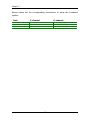
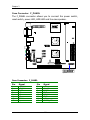
User’s Manual
EPIA-SP
Version 1.0
August 2, 2004
Copyright
Copyright © 2004 VIA Technologies Incorporated. All rights reserved.
No part of this document may be reproduced, transmitted, transcribed, stored in a retrieval
system, or translated into any language, in any form or by any means, electronic, mechanical,
magnetic, optical, chemical, manual or otherwise without the prior written permission of VIA
Technologies, Incorporated.
Trademarks
All trademarks are the property of their respective holders. PS/2 is a registered trademark of
IBM Corporation. Award BIOS is a registered trademark of Phoenix Technologies Ltd.
Disclaimer
No license is granted, implied or otherwise, under any paten or patent rights of VIA
Technologies. VIA Technologies makes no warranties, implied or otherwise, in regard to this
document and to the products described in this document. The information provided in this
document is believed to be accurate and reliable as of the publication date of this document.
However, VIA Technologies assumes no responsibility for the use or misuse of the information
in this document and for any patent infringements that may arise from the use of this
document. The information and product specifications within this document are subject to
change at any time, without notice and without obligation to notify any person of such change.
FCC-B Radio Frequency Interference Statement
This equipment has been tested and found to comply with the limits for a class B digital
device, pursuant to part 15 of the FCC rules. These limits are designed to provide reasonable
protection against harmful interference when the equipment is operated in a commercial
environment. This equipment generates, uses and can radiate radio frequency energy and, if not
installed and used in accordance with the instruction manual, may cause harmful interference
to radio communications. Operation of this equipment in a residential area is likely to cause
harmful interference, in which case the user will be required to correct the interference at his
personal expense.
Notice 1
The changes or modifications not expressly approved by the party responsible for compliance
could void the user's authority to operate the equipment.
Notice 2
Shielded interface cables and A.C. power cord, if any, must be used in order to comply with
the emission limits.
Tested To Comply
With FCC Standards
FOR HOME OR OFFICE USE
Safety Instructions
1.
Always read the safety instructions carefully.
2.
Keep this User's Manual for future reference.
3.
Keep this equipment away from humidity.
4.
Lay this equipment on a reliable flat surface before setting it up.
5.
The openings on the enclosure are for air convection hence protects the equipment from
6.
Make sure the voltage of the power source and adjust properly 110/220V before
overheating. DO NOT COVER THE OPENINGS.
connecting the equipment to the power inlet.
7.
Place the power cord in such a way that people cannot step on it. Do not place anything
8.
Always unplug the power cord before inserting any add-on card or module.
9.
All cautions and warnings on the equipment should be noted.
over the power cord.
10. Never pour any liquid into the opening. Liquid can cause damage or electrical shock.
11. If any of the following situations arises, get the equipment checked by a service personnel:
•
The power cord or plug is damaged
•
Liquid has penetrated into the equipment
•
The equipment has been exposed to moisture
•
The equipment has not work well or you cannot get it work according to User's
Manual.
•
The equipment has dropped and damaged
•
If the equipment has obvious sign of breakage
12. DO NOT LEAVE THIS EQUIPMENT IN AN ENVIRONMENT UNCONDITIONED,
STORAGE TEMPERATURE ABOVE 60 C (140F), IT MAY DAMAGE THE
EQUIPMENT.
CAUTION: Explosion or serious damage may occur if the battery is
incorrectly replaced.
Replace only with the same or equivalent
battery type recommended by the manufacturer.
BOX CONTENTS
One
One
One
One
One
VIA Mini-ITX mainboard
Quick Installation Guide
ATA-133/100 IDE ribbon cable
driver and utilities CD
IO bracket
i
TABLE OF CONTENTS
Box Contents ............................................................................... i
Table of Contents .........................................................................ii
Chapter 1 ................................................................................... 1
Specifications........................................................................... 1
Mainboard Specifications .......................................................... 2
Mainboard Layout .................................................................... 4
Back Panel Layout .................................................................... 5
Back Panel Ports ...................................................................... 6
Slots ....................................................................................... 6
Onboard Connectors................................................................. 7
Onboard Jumpers..................................................................... 7
Chapter 2 ................................................................................... 9
Installation .............................................................................. 9
CPU ...................................................................................... 10
Memory Module Installation .................................................... 14
Connecting the Power Supply.................................................. 17
Back Panel Ports .................................................................... 19
Connectors ............................................................................ 23
Jumpers ................................................................................ 38
Slots ..................................................................................... 41
Chapter 3 ................................................................................. 43
BIOS Setup............................................................................ 43
Entering Setup ....................................................................... 44
Control Keys .......................................................................... 45
Navigating the BIOS Menus .................................................... 46
Getting Help .......................................................................... 47
Main Menu............................................................................. 48
Standard CMOS Features ........................................................ 50
IDE Drives ............................................................................. 51
Advanced BIOS Features ........................................................ 52
Hard Disk Boot Priority ........................................................... 55
Advanced Chipset Features ..................................................... 56
ii
Integrated Peripherals ............................................................ 59
Super IO Device..................................................................... 61
Power Management Setup ...................................................... 63
Peripheral Activities ................................................................ 65
IRQs Activities ....................................................................... 68
PNP/PCI Configurations .......................................................... 69
IRQ Resources ....................................................................... 71
PC Health Status .................................................................... 72
Frequency / Voltage Control.................................................... 73
Load Fail-Safe Defaults ........................................................... 76
Load Optimized Defaults ......................................................... 77
Set Supervisor / User Password............................................... 78
Save & Exit Setup .................................................................. 80
Exit Without Saving ................................................................ 81
Chapter 4 ................................................................................. 83
Driver Installation................................................................... 83
Driver Utilities ........................................................................ 84
CD Content............................................................................ 86
iii
This page left intentionally blank.
iv
CHAPTER 1
Specifications
The ultra-compact and highly integrated VIA EPIA-SP uses the MiniITX mainboard form-factor developed by VIA Technologies, Inc. as
part of the company’s open industry-wide total connectivity initiative.
The mainboard enables the creation of an exciting new generation of
small, ergonomic, innovative and affordable embedded systems.
Through a high level of integration, the Mini-ITX occupy 66% of the
size of FlexATX mainboard form factor. The mainboard comes with
an embedded VIA Processor, boasting of ultra-low power
consumption, cool and quite operation.
1
Chapter 1
MAINBOARD SPECIFICATIONS
CPU
•
VIA C3 / Eden EBGA Processor
Chipset
•
VIA CN400 North Bridge
•
VIA VT8237 South Bridge
Graphics
•
Integrated UniChrome™ Pro AGP with MPEG-2 decoder / MPEG-4
Acceleration
Audio
•
VIA VT1617A 6-channel AC'97 Codec
Memory
•
1 x DDR 400 / 333 / 266 DIMM socket (up to 1 GB)
Expansion Slot
•
1 x PCI slot
•
2 x UltraDMA 133/100 connectors, with Direct DOM Support
IDE
LAN
•
VIA VT6103 10/100 Base-T Ethernet PHY
IEEE 1394
•
VIA VT6307S IEEE 1394 Fire Wire
TV-Out
•
VIA VT1623 TV Encoder
2
Specifications
Back Panel I/O Ports
•
1 x PS/2 mouse port
•
1 x PS/2 keyboard port
•
1 x RJ-45 LAN port
•
1 x Serial port
•
2 x USB 2.0 ports
•
1 x RCA port (SPDIF or TV out)
•
1 x S-Video port
•
1 x VGA port
•
3 x Audio Jacks: line-out, line-in and mic-in (Horizontal, Smart 5.1
Support)
Onboard I/O Connectors
•
3 x USB connectors for 6 additional USB 2.0 ports
•
1 x IEEE 1394 connector
•
1 x Serial port connector for COM2
•
1 x VIP connector
•
1 x Front Panel audio connector (Mic-in and Line-out)
•
1 x CD audio-in connector
•
1 x FIR connector
•
1 x KBMS connector (KB/MS or CIR)
•
1 x LPT port connector
•
1 x Wake On LAN connector
•
2 x Fan connectors (CPU Fan and System Fan)
•
1 x +12V power connector
•
1 x SMBus connector
•
1 x LVDS
BIOS
•
Award BIOS with 4/8Mbit flash memory capacity
•
ACPI2.0, SMBIOS2.1 and DMI2.2
Form Factor
•
Mini-ITX (6 layers)
•
17 cm X 17 cm
3
Chapter 1
MAINBOARD LAYOUT
Top: Mouse
Bottom: Keyboard
CPUFAN
ATXPWR
KBMS
C3TM Processor
DIMM1
Top: COM1
Bottom: VGA port
+12V_PWR
SMBus
Top: RJ45 port
Bottom: USB port
CN400
S-Video port
RCA Jack
SPDIF_SEL1
COM2
LPT
USB 3/4
USB 5/6
VT8237
FIR
F_AUDIO CD_IN
Microphone
J1
LVDS
Line-Out
Line-In
SYSFAN
USB 7/8
WP
BIOS
Socket
CLEAR_CMOS
SATA_1 SATA_2
WOL
SPDIF
CMOS battery
1394_1
PCI Slot
4
IDE1 IDE2
VIP_2
F_PANEL
Specifications
BACK PANEL LAYOUT
PS/2 Mouse
COM1
RJ45
RCA / SPDIF
PS/2 Keyboard
VGA Out
USB
S-Video
5
Line-Out Line-In
Microphone
Chapter 1
BACK PANEL PORTS
Port
Description
Audio Jacks
COM1
PS/2 Mouse
PS/2 Keyboard
RCA/SPDIF
RJ45
USB
VGA
S-Video
3 Audio ports (line-out, line-in and mic-in)
Serial port 1
PS/2 mouse port
PS/2 keyboard port
RCA port (SPDIF or TV out)
RJ45 port
USB 2.0 ports
VGA port
S-Video port
Page
19-22
19
19
19
19-20
19-20
19-20
19
19-20
SLOTS
Port
Description
DDR DIMM
PCI
Memory module slot
Expansion card slot
Page
14-16
41-42
6
Specifications
ONBOARD CONNECTORS
Connector
Description
+12V_CONN
1394_1
ATXPWR
CD_IN
COM 2
CPUFAN
FIR
F_AUDIO
F_PANEL
IDE 1-2
KBMS Header
LPT
LVDS
SATA1 and 2
SMBus_Header
SYSFAN
USB 3-4/5-6/7-8
VIP_2
WOL
12V Power connector
IEEE 1394 connector
Power cable connector
Onboard CD audio cable connector
COM port 2 connector
CPU fan connector
Fast Infrared Radiation connector
Front Audio pin connector
Front panel connector
IDE drive connectors
Keyboard and Mouse connector
Parallel port connector
LVDS connector
Serial ATA 1 and 2 connectors
SMBus pin connector
System fan connector
Universal Serial Bus 2.0 connectors 3-4/5-6/7-8
VIP pin connector
Wake On LAN connector
Page
12-13
31-32
17-18
31-32
31-32
12
28
33-34
26-27
23-24
38, 40
28-29
36-37
25
33
12
30
35
31
ONBOARD JUMPERS
Jumper
Description
CLEAR_CMOS
J1
SPDIF_SEL
WP
Reset CMOS settings
IDE selector
S/PDIF selector
BIOS write protection setting
Page
7
38-39
38, 40
38, 40
38, 40
Chapter 1
This page left intentionally blank.
8
CHAPTER 2
Installation
This chapter provides you with information about hardware
installation procedures. It is recommended to use a grounded wrist
strap before handling computer components. Electrostatic discharge
(ESD) can damage some components.
9
Chapter 2
CPU
The VIA C3 E-Series Processor
The VIA EPIA-SP Mini-ITX mainboard includes an embedded VIA C3 or Eden
Processor. The VIA C3 Processor provides ultra-low power consumption and
advanced thermal dissipation properties. The VIA C3 Processor requires
heatsink and a CPU fan to provide sufficient cooling. Ensure that the CPU
fan is correctly installed as shown.
10
Installation
The VIA Eden Processor
Providing ultra-low power consumption and advanced thermal dissipation
properties, the VIA Eden Processor features a fanless design. The VIA Eden
Processor requires only a heatsink as shown.
WARNING: This mainboard is not designed to support overclocking.
Any attempt to operate beyond product specifications is not
recommended. We do not guarantee the damage or risks caused by
inadequate operation or beyond product specifications.
11
Chapter 2
CPU Fan and System Fan: CPUFAN and SYSFAN
The CPUFAN (CPU fan) and SYSFAN (system fan) run on +12V and maintain
system cooling. When connecting the wire to the connectors, always be
aware that the red wire is the Positive and should be connected to the +12V.
The black wire is Ground and should always be connected to GND. The CPU
system and power fan connectors have sensors to support fan monitoring
except for +12V_CONN.
1
1
+12V_CONN
1
SYSFAN
CPUFAN
C3TM Processor
CN400
VT8237
12
Installation
+12V Power Connector
This 12V power connector is used to provide additional +12V power to the
rest of the system.
Pin
Signal
1
2
+12V
GND
1
+12V_CONN
13
Chapter 2
MEMORY MODULE INSTALLATION
The VIA EPIA-SP Mini-ITX mainboard provides one 184-pin DIMM slot for
DDR400/333/266 SDRAM memory modules and supports the memory size
up to 1GB.
DDR SDRAM Module Installation Procedures
•
Locate the DIMM sockets in the motherboard.
C3TM Processor
CN400
VT8237
DIMM1
14
Installation
•
Unlock a DIMM socket by pressing the retaining clips outward.
•
Align a DIMM on the socket such that the notch on the DIMM
matches the break on the socket.
•
Firmly insert the DIMM into the socket until the retaining clips snap
back in place and the DIMM is properly seated.
15
Chapter 2
Available DDR SDRAM Configurations
Refer to the table below for available DDR SDRAM configurations on the
mainboard.
Slot
Module Size
Total
DIMM
64MB, 128MB, 256MB, 512MB, 1GB
Maximum supported system memory
16
64MB-1GB
64MB-1GB
Installation
CONNECTING THE POWER SUPPLY
The VIA EPIA-SP Mini-ITX mainboard supports a conventional ATX power
supply for the power system. Before inserting the power supply connector,
always make sure that all components are installed correctly to ensure that
no damage will be caused.
ATX 20-Pin Power Connector
To connect the ATX power supply, make sure the power plug is inserted in
the proper orientation and the pins are aligned. Then push down the plug
firmly into the connector.
1
ATXPWR
C3TM Processor
CN400
VT8237
17
Chapter 2
ATX 20 Pin Power Connector
Pin
Signal
Pin
Signal
1
2
3
4
5
6
7
8
9
10
+3.3V
+3.3V
GND
+5V
GND
+5V
GND
Power Good
+5V Standby
+12V
11
12
13
14
15
16
17
18
19
20
+3.3V
-12V
GND
Power Supply On
GND
GND
GND
NC
+5V
+5V
18
Installation
BACK PANEL PORTS
The back panel has the following ports:
PS/2 Mouse
COM1
RJ45
RCA / SPDIF
PS/2 Keyboard
VGA Out
USB
S-Video
Line-Out Line-In
Microphone
Keyboard and Mouse
The green 6-pin connector is for a PS/2 mouse. The purple
connector is for a PS/2 keyboard.
VGA Out
The 15-pin female VGA connector can be used
to connect to any analog VGA monitor.
Serial port: COM 1
This 9-pin COM 1 port is for pointing devices or
other serial devices.
19
Chapter 2
RJ45 10/100 LAN Connector
The mainboard provides a standard RJ-45 port. This port
allows connection to a Local Area Network (LAN)
through a network hub
USB 2.0 ports 1and 2
These two 4-pin Universal Serial Bus (USB) ports
are available for connecting USB 2.0 devices.
S-Video port
This port allows you to connect TV monitor or S-video device
to the mainboard.
SPDIF jack
This jack connects to external audio output devices.
20
Installation
Audio Port:
Line Out jack
This Line Out (lime) jack connects a headphone or a speaker. In 6-channel
mode, the function of this jack becomes Front Speaker Out.
Line In jack
This Line In (light blue) jack connects a tape player or other audio devices.
In 6-channel mode, the function of this jack becomes Rear Speaker Out.
Microphone jack
This Mic (pink) jack connects a microphone. In 6-channel mode, the
function of this jack becomes Bass / Center Speaker Out.
Note:
The audio ports can be switched to Smart 5.1 6-channel audio
output. You can enable the function by clicking the “Vinyl Audio” icon
on your desktop after installing the audio driver.
After completing the previous installation, connect the speakers to the 3-jack
connectors on the back panel as shown.
PS/2 Mouse
COM1
RJ45
RCA / SPDIF
PS/2 Keyboard
VGA Out
USB
S-Video
21
Line-Out Line-In
Microphone
Chapter 2
Shown below are the corresponding connections to setup the 6-channel
system.
Jack
2-channel
6-channel
Line-out
Line-in
Microphone
Line-out
Line-in
Microphone
Front (Left/Right)
Rear (Left/Right)
Center/Sub-woofer
22
Installation
CONNECTORS
Hard Disk Connectors: IDE1 & IDE2
The mainboard has a 32-bit Enhanced IDE and Ultra DMA 133/100 controller
that provides PIO mode 0~4, Bus Master, and Ultra DMA 133/100 functions.
You can connect up to four hard disk drives, CD-ROM and other devices.
The primary hard drive should always be connected to IDE1 as the master
drive. Both IDE drives can connect to a master and a slave drive.
C3TM Processor
IDE2
1
1
CN400
IDE1
VT8237
23
Chapter 2
If two drives are connected to a single cable, the jumper on the second
drive must be set to slave mode. Refer to the drive documentation supplied
by the vendor for the jumper settings. Both IDE1 and IDE2 have a 20th pin
included. The 20th pin was added to provide extra voltage to power 40-pin
Disk-on Modules (DOM). See voltage selector: J1 on page 38 and 40. You
must use IDE cables that do not block the 20th pin.
24
Installation
Serial ATA Connectors: SATA1 and SATA2
These next generation connectors support the thin Serial ATA cables for
primary internal storage devices. The current Serial ATA interface allows up
to 150MB/s data transfer rate, faster than the standard parallel ATA with
133 MB/s (Ultra DMA).
C3TM Processor
CN400
VT8237
SATA_1 SATA_2
25
Chapter 2
Case Connector: F_PANEL
The F_PANEL connector allows you to connect the power switch,
reset switch, power LED, HDD LED and the case speaker.
C3TM Processor
CN400
VT8237
1
F_PANEL
Case Connector: F_PANEL
Pin
Signal
Pin
Signal
1
3
5
7
9
11
13
15
+5VDUAL
+5VDUAL
-PLED
+5V
NC
NC
SPEAK
Key
2
4
6
8
10
12
14
16
+5V
HD_LED
PW_BN
GND
RST_SW
GND
+5V
-SLEEP_LED
26
Installation
Power Switch (PW_BN)
Connect to a 2-pin power button switch. Pressing this button will turn the
system power on or off.
Reset Switch (RST_SW)
The reset switch is used to reboot the system rather than turning the power
ON/OFF. Avoid rebooting the system, if the HDD is still working. Connect
the reset switch from the system case to this pin.
Power LED (-PLED)
The LED will light when the system is on. If the system is in S1 (POS Power On Suspend) or S3 (STR - Suspend To RAM) state, the LED will blink.
HDD LED (HD_LED)
HDD LED shows the activity of a hard disk drive. Avoid turning the power
off when the HDD LED still has a lit. Connect the HDD LED from the system
case to this pin.
27
Chapter 2
Fast IrDA Infrared Module Connector: FIR
This connector is used to connect to an IrDA module. The BIOS settings
must be configured to activate the IR function.
Pin
Signal
Description
1
2
3
4
5
+5V
IRRX1
IRRX
GND
IRTX
VCC
FIR/SIR Data Receive
SIR Data Receive
Ground
FIR/SIR Data Transmit
C3TM Processor
CN400
1
FIR
VT8237
1
LPT
1
SPDIF
28
Installation
Digital Audio Connector: S/PDIF
This connector is for connecting the Sony Philips Digital Interface (S/PDIF)
bracket. The S/PDIF output provides digital audio to external speakers or
compressed AC3 data to an external Dolby Digital Decoder. The feature is
available only with stereo system that has digital output function.
Pin
Signal
1
2
3
+5V
S/PDIF
GND
1
SPDIF
Parallel Port Connector: LPT
The mainboard provides a 25-pin port to be able to connect a 25-pin female
external connector for LPT (parallel port). A parallel port is a standard
printer port that supports Enhanced Parallel Port (EPP) and Extended
Capabilities Parallel Port (ECP) modes.
Pin
Signal
Pin
Signal
1
2
3
4
5
6
7
8
9
10
11
12
13
STROBE
DATA0
DATA1
DATA2
DATA3
DATA4
DATA5
DATA6
DATA7
ACK#
BUSY
PE
SELECT
14
15
16
17
18
19
20
21
22
23
24
25
AUTO FEED#
ERR#
INIT#
SLIN#
GND
GND
GND
GND
GND
GND
GND
GND
29
1
LPT
Chapter 2
USB Pin Connectors: USB 3-4, 5-6, and 7-8
The mainboard provides 3 front USB pin–header connectors, allowing up to
6 additional USB2.0 ports up to maximum throughput of 480 Mbps. Connect
each 2-port USB cable into each pin-headers. These ports can be used to
connect high-speed USB interface peripherals such as USB HDD, digital
cameras, MP3 players, printers, modem and the like.
C3TM Processor
CN400
1
USB 3/4
1
VT8237
USB 5/6
1
USB 7/8
USB connectors: USB 3-4, 5-6, and 7-8
Pin
Signal
Pin
Signal
1
3
5
7
9
USBVCC
USBD_T2USBD_T2+
GND
Key
2
4
6
8
10
USBVCC
USBD_T3USBD_T3+
GND
GND
30
Installation
Wake-On LAN: WOL
This connector allows you to connect a network card with the Wake-On LAN
function. The connector will power up the system when a signal is received
through the network card. Please note that the function of ACPI WOL may
be disabled when users will unplug the power cord or turn off the power
button manually.
C3TM Processor
CN400
1
VT8237
COM2
1
CD_IN
1
1
1394
WOL
Wake-On LAN connector: WOL
Pin
Signal
Description
1
2
3
+5VDUAL
GND
WOL IN
VCC
Ground
Wake on LAN Input
31
Chapter 2
Serial Port: COM 2
COM2 can be used to attach additional port for serial mouse or
another serial device.
Pin
Signal
Pin
Signal
1
3
5
7
9
DCD
SOUT
GND
RTS
RI
2
4
6
8
10
SIN
DTR
DSR
CTS
Key
1
COM2
CD Audio Connector: CD_IN
This connector allows you to receive stereo audio input from sound source
such as a CD-ROM.
Pin
Signal
1
2
3
4
Left channel
GND
GND
Right channel
1
CD_IN
FireWire: IEEE1394
FireWire is a serial I/O interface that provides you fast data transfer rates.
The mainboard has one FireWire port to provide PC connectivity for a wide
range of devices, including consumer electronics audio/video (A/V)
appliances, storage peripherals, other PCs and portable devices.
Pin
Signal
Pin
Signal
1
3
5
7
9
TPA0+
GND
TB0+
1394_VDD
GND
2
4
6
8
10
TPA0GND
TPB01394_VDD
Key
32
1
1394
Installation
System Management Bus Connector: SMBus
The connector allows you to connect SMBus (System Management Bus)
devices.
Devices communicate with an SMBus host and/or other SMBus
devices using the SMBus interface.
Pin
Signal
1
2
3
SMBCK
SMBDT
GND
C3TM Processor
1
CN400
1
VT8237
F_AUDIO
33
SMBus
Chapter 2
Front Panel Audio Connector: F_AUDIO
This is an interface for the VIA front panel audio cable that allow convenient
connection and control of audio devices.
By default, the pins labeled
LINE_OUT_R/NEXT_R and the pins LINE_OUT_L/NEXT_L are shorted with
jumper caps.
Remove the caps only when you are connecting the front
panel audio cable.
Pin
Signal
Description
1
2
3
4
5
6
7
8
9
10
FRNMIC
AGND
MIC_BIAS
+5V AUDIO
LINE_OUT_R
NEXT_R
NC
Key
LINE_OUT_L
NEXT_L
Front panel microphone input
Ground used by analog audio circuit
Microphone power
VCC used by analog audio circuit
Right channel audio signal
Right channel audio signal return
No connection
No pin
Left channel audio signal
Left channel audio signal return
1
F_AUDIO
Note:
If you don’t want to connect to the front audio header, pins 5 & 6, 9 &
10 have to be jumpered in order to have signal output directed to the
rear audio ports. Otherwise, the Line-Out connector on the back
panel will not function.
34
Installation
Video Interface Port Pin Connector: VIP_2
This connector allows you to use the capture function inside the North
Bridge.
Pin
Signal
Pin
Signal
1
3
5
7
9
11
13
15
GND
CAPD7
CAPD6
GFPHS
CAPD1
GFPVS
SMBDT
SMBCK
2
4
6
8
10
12
14
16
CAPD0
CAPD4
CAPD5
CAPD2
CAPD3
CAPCLK
KEY
GND
C3TM Processor
CN400
VT8237
1
VIP_2
35
Chapter 2
LVDS Connector:
This connector is for devices requiring display interface such as LVDS, and
TTL. The LVDS connector may not be available on your mainboard. This is
an option that is added during the manufacturing process. If you would like
a mainboard with the LVDS connector, please contact your vendor or sales
contact for more information.
C3TM Processor
CN400
LVDS
VT8237
36
Installation
LVDS Connector
Pin
Signal
Pin
Signal
1
3
5
7
9
11
13
15
17
19
21
23
25
27
29
31
33
35
37
39
41
43
45
47
49
GND
GFPCLK
GND
GFPD12
GFPD11
GFPD1
GND
GFPD6
GFPD7
GFPD0
GND
GFPD4
GFPD8
GND
GFPD5
GFPD9
GND
GFPD10
GFPD13
GND
ENPVDD
ENPVEE
FPBKLP
PWRGD_SB
+3.3V
2
4
6
8
10
12
14
16
18
20
22
24
26
28
30
32
34
36
38
40
42
44
46
48
50
+5V
+5V
GND
GFPD15
GFPD14
GFPD3
GND
GFPD16
GFPD17
GFPD2
GND
GFPD18
GFPD19
GND
GFPD21
GFPD20
GND
GFPD22
GFPD23
GND
GFPVS
GFPHS
GFPDE
TVBSCK_R
TVBSDA_R
Note:
ENPVDD: Enable Panel VDD power
ENVEE: Enable panel VEE power
GFPD: Graphic Flat Panel Device signals.
37
Chapter 2
JUMPERS
The mainboard provides jumpers for setting some mainboard functions.
This section will explain how to change the settings of the mainboard
functions using the jumpers.
1
C3TM Processor
KBMS
CN400
1
J1
1
RCA/SPDIF
VT8237
1
1
WP
CLEAR_CMOS
38
Installation
Clear CMOS: CLEAR_CMOS
This jumper allows you to clear the Real Time Clock (RTC) RAM in CMOS.
You can clear the CMOS memory of date, time and system setup parameters
by erasing the CMOS RTC RAM data. The onboard
1
1
button cell battery powers the RAM data in CMOS
that include system setup information such as
system passwords.
1-2: Normal (Default)
2-3: Clear CMOS
To erase the RTC RAM:
1.
Turn OFF the computer and unplug the power cord.
2.
Remove the onboard battery
3.
Move the jumper cap from pins 1-2 (default) to pins 2-3. Keep cap
on pins 2-3 for about 5~10 seconds, then move the cap back to pins
1-2.
4.
Replace the battery.
5.
Plug the power cord and turn ON the computer.
6.
Hold down the <Del> key during the boot process and enter BIOS
setup to re-enter data.
WARNING: Except when clearing the RTC RAM, never remove the
cap on CLEAR_CMOS jumper default position. Removing the cap
will cause system boot failure. Avoid clearing the CMOS while the
system is on; it will damage the mainboard.
39