1
Page: 1
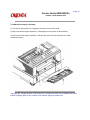
Service Guide OKIPAGE16n
Chapter 0 About This Manual
OKIPAGE 16n
LED Page Printer
Adobe Acrobat printable reference
copy of the OKIDATA Service Training Manual.
09/17/97
Note: This Adobe Acrobat version of the Okidata Service Training Manual was built with the
pictures rendered at 300 dpi, which is ideal for printing, but does not view on most
displays well.
Copyright 1997, Okidata, Division of OKI America, Inc. All rights reserved. See the OKIDATA Business
Partner Exchange (BPX) for any updates to this material. (http://bpx.okidata.com)
Table of Contents
Page
Service Guide OKIPAGE16n
0 About This Manual
Front Cover
1 Configuration
1.1 System Configuration
1.2 Printer Configuration
1.3 Optional Configuration
1.4 Specification
1.5 Safety Standards
....1.5.2 Warning Label
2 Operation Description
2. OPERATION DESCRIPTION
2.1 Main Control Board (BOARD-COM)
2.2 Power Supply Board
2.3 Relay/Driver Board (AOLC board)
2.4 Electrophotographic Process
....2.4.1 Electrophotographic process mechanism
....2.4.2 Electrophotographic process
....2.4.3 Process operation descriptions
2.5 Paper Jam Detection
2.6 Cover Open
2.7 Toner Low Detection
2.8 Stacker-full Detection
2.9 Page Size Detection
2.10 PostScript Board (BOARD-PSBA) Optional
3 Parts Replacement
3. PARTS REPLACEMENT
3.1 Precautions for Parts Replacement
3.2 Parts Layout
3.3 How to Change Parts
....3.3.1 Rear cover, side cover (L) Assembly, face-up stacker
Assembly, and I/F cover Assembly.
....3.3.2 Contact Assembly
....3.3.3 DC fan motor
....3.3.4 Manual feed hopper Assembly
....3.3.5 Side cover (R) (operator panel Assembly)
....3.3.6 Earth plate BK (R) (BOARD-PSBA, BOARD-COM)
....3.3.7 Stacker cover Assembly, damper arm, and washer
....3.3.8 Damper
....3.3.9 Stacker full sensor Assembly
....3.3.10 Cable cover (cable guides A and B)
....3.3.11 Eject roller Assembly
....3.3.12 Paper supply guide D
1
2
3
4
5
6
7
8
9
10
11
12
13
14
15
16
17
18
19
20
21
22
23
24
25
26
27
28
29
30
31
32
33
34
35
36
37
Table of Contents
....3.3.13 Separator F
....3.3.14 Front feeder roller Assy
....3.3.15 Hopping motor
....3.3.16 Front feeder paper end sensor
....3.3.17 Main chassis unit
....3.3.18 Registration roller
....3.3.19 Drum motor
....3.3.20 Idle gear
....3.3.21 Fusing Assembly
....3.3.22 Fuser pressure roller
....3.3.23 EP lock shaft
....3.3.24 Hopping roller Assembly
....3.3.25 Outlet sensor lever
....3.3.26 Toner sensor lever
....3.2.27 Paper sensor lever
....3.3.28 Inlet sensor lever
....3.3.29 Power Supply Board / Insulator
....3.3.30 Paper end lever
....3.3.31 Guide rail (L) Assembly
....3.3.32 Guide rail (R) Assembly
....3.3.33 Cover Frame
....3.3.34 LED head
....3.3.35 Separator Assembly
....3.3.36 Transfer roller
4 Adjustment
4. ADJUSTMENT
4.1 Maintenance Modes And Functions
....4.1.1 User maintenance mode
....4.1.1 User maintenance mode menu system
....4.1.2 System maintenance mode
....4.1.3 Engine maintenance mode
....4.1.4 EEPROM initialization
4.2 Adjustment When Replacing A Part
....4.2.1 Setting of LED head drive time
....4.2.2 Resetting the fuser counter
....4.2.3 Destination setting
5 Periodical Maintenance
5.1 Periodic Part Replacement
5.2 Cleaning
....5.2.1 Cleaning of LED lens array
6 Troubleshooting Procedures
6.1 Troubleshooting Tips
6.2 Points to Check before Correcting Image Problems
6.3 Tips for Correcting Image Problems
Page
38
39
40
41
42
43
44
45
46
47
48
49
50
51
52
53
54
55
56
57
58
59
60
61
62
63
64
65
66
67
68
69
70
71
72
73
74
75
76
77
78
Table of Contents
6.4 Preparation for Troubleshooting
....Operator Panel Display
6.5 Troubleshooting Flow
....6.5.1 LCD Status Message/Trouble List
....6.5.2 LCD message troubleshooting
........1 The printer does not work normally after being turned
on.
........2 [JAM error]
............2-1 Paper input jam (1st tray)
............2 - 2 Paper input jam (front feeder)
............2 - 3 Paper feed jam
............2-4 Paper exit jam
........3 Paper size error
........4 Fuser unit error (ERROR 71), (ERROR 72), (ERROR
73)
........5 I/F time-out between printer and optional tray (ERROR
81)
........6 I/F time-out occurs between the printer and the operator
panel (ERROR 80) .
........7 Communication with the host cannot be performed via
the parallel interface
........8 Data cannot be received through the OKI HSP interface
........9 Synchronous serial I/O error (ERROR 74)
....6.5.3 Image troubleshooting
........1 Image are light or blurred
........2 Dark background density
........3 Black paper is output
........4 Black belts or stripes in the vertical direction
........5 Cyclic error
........6 Print voids
........7 Poor fusing
........8 White belts or streaks in the vertical direction
........9 Snowy print of high density pattern
........10 Blotchy faded print
7 Wiring Diagram
7.1 Interconnect Signal Diagram
7.2 PCB Layout
7.3 Resistance Check
Program/Font ROM Location
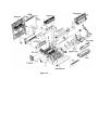
8 Parts List
8. PARTS LIST
Printer Unit (Figure 8-1)
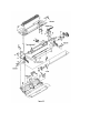
Main Chassis Unit (Figure 8-2) 1 of 2
Main Chassis Unit (Figure 8-2) 2 of 2
Page
79
80
81
82
83
84
85
86
87
88
89
90
91
92
93
94
95
96
97
98
99
100
101
102
103
104
105
106
107
108
109
110
111
112
113
114
115
Table of Contents
Front Feeder Unit (Figure 8-3)
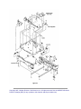
Base Unit (Figure 8-4)
A Centronics Parallel Interface
Appendix A: Centronics Parallel Interface
B High Capacity Second Paper Feeder
Preface
1. Outline
....1.1 Functions
....1.2 External View and Component Names
2. Mechanism Description
....2.1 General Mechanism
....2.2 Hopper Mechanism
3. Parts Replacement
....3.1 Precautions Concerning Parts Replacement
....3.2 Parts Layout
....3.3 Parts Replacement Methods
........3.3.1 Idle rollers
........3.3.2 AOLT-PCB
........3.3.3 Hopping motor
........3.3.4 Feed roller
........3.3.5 Hopping roller rubber
........3.3.6 Side frame (L) assy
........3.3.7 Side frame (R) assy
....4. TROUBLESHOOTING
........4.1 Precautions Prior to the Troubleshooting
........4.2 Preparations for the Troubleshooting
........4.3 Troubleshooting Method
............4.3.1 LCD Status Message List
............4.3.2 Troubleshooting Flow
....5. Connect Diagram
........5.1 Interconnection Diagram
........5.2 PCB Layout
....6. Parts List
C Multi Feeder Maintenance
Preface
1. Outline
....1.1 Functions
....1.2 External View and Component Names
2. Mechanism Description
....2.1 General Mechanism
....2.2 Hopper Mechanism
3. Parts Replacement
....3.1 Precautions Concerning Parts Replacement
....3.2 Parts Layout
Page
116
117
118
119
120
121
122
123
124
125
126
127
128
129
130
131
132
133
134
135
136
137
138
139
140
141
142
143
144
145
146
147
148
149
150
151
152
153
154
155
156
Table of Contents
....3.3 Parts Replacement Methods
........3.3.1 Separator
........3.3.2 AOLE-PCB
........3.3.3 Square-shaped connector
........3.3.4 Hopping Motor
........3.3.5 Planet gear
........3.3.6 Roller B
........3.3.7 Roller A
........3.3.8 Mini pitch belt & Feed roller
4. Troubleshooting
....4.1 Precautions Prior to Troubleshooting
....4.2 Preparations for Troubleshooting
....4.3 Troubleshooting Method
........4.3.1 LCD Status Message List
........4.3.2 Troubleshooting Flow
5. Connection Diagram
....5.1 Interconnection Diagram
5.2 PCB Layout
6. Parts List
D Localtalk Serial Interface (OKIPAGE16n/PS Only)
Localtalk Serial Interface (OKIPAGE 16n/PS Only)
Page
157
158
159
160
161
162
163
164
165
166
167
168
169
170
171
172
173
174
175
176
Page: 2
Service Guide OKIPAGE16n
Chapter 1 Configuration
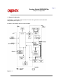
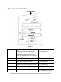
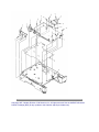
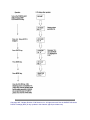
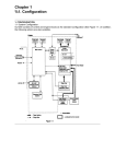
1.1 System Configuration
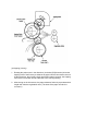
OKIPAGE16n / OKIPAGE16n/PS consists of control and engine blocks as the standard
configuration (See Figure 1-1.)
In addition, the following options are also available.
Figure 1-1
Copyright 1997, Okidata, Division of OKI America, Inc. All rights reserved. See the OKIDATA Business
Partner Exchange (BPX) for any updates to this material. (http://bpx.okidata.com)
Page: 3
Service Guide OKIPAGE16n
Chapter 1 Configuration
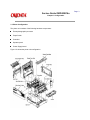
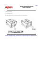
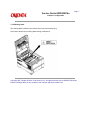
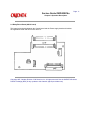
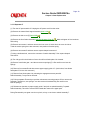
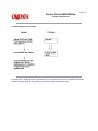
1.2 Printer Configuration
The printer unit consists of the following hardware components:
Electrophotographic processor
Paper feeder
Controller
Operator panel
Power Supply board
Figure 1-2 shows the printer unit configuration.
Figure 1-2
Copyright 1997, Okidata, Division of OKI America, Inc. All rights reserved. See the OKIDATA Business
Partner Exchange (BPX) for any updates to this material. (http://bpx.okidata.com)
Page: 4
Service Guide OKIPAGE16n
Chapter 1 Configuration
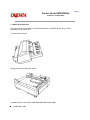
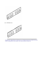
1.3 Optional Configuration
The options below are available for use with OKIPAGE16n / OKIPAGE16n/PS. They are sold
separately from the printer unit.
(1) Multi-Purpose Feeder
(2) High Capacity Second Paper Feeder
(3) RAM module (72 pin SIMM, 1 MB/2 MB/4 MB/8 MB/16 MB/32 MB)
16 MB RAM module
8 MB RAM module
Copyright 1997, Okidata, Division of OKI America, Inc. All rights reserved. See the OKIDATA Business
Partner Exchange (BPX) for any updates to this material. (http://bpx.okidata.com)
Page: 5
Service Guide OKIPAGE16n
Chapter 1 Configuration
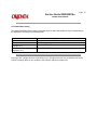
1.4 Specification
(1) Type
Desk top
(2) External dimensions
(excludes protruding
Portion)
Height 10.6" (270 mm)
Width 14.4" (366 mm)
Depth 16.9" (430 mm)
(3) Weight
15.2 kg (33.5 lbs)
(4) Development method
Exposure method
Dry electrophotography
LED stationary head
(5) Paper used <Type>
Standard paper
- Xerox 4200 (20 lbs)
Application paper (manual face-up feed)
- Label
- Envelope
- OHP paper (Transparency)
<Size>
Standard sizes
- Letter
- Legal
- Executive
- Envelope
- A4
- A5
- B5
- A6
Applicable sizes
- Width: 3.4" to 8.5" (86 to 216 mm)
- Length: 5.5" to 14" (140 to 355.6 mm)
<Thickness>
- Automatic feed:
- Manual feed:
16 to 28 lbs (60 to 105 g/m 2 )
Label, OHP paper (transparency)
Envelope
(6) Printing speed
Continuous print:
Warm-up time:
First print: 10 sec.
16 sheets/min.
90 sec. [at room temperature 77°F
(25°C) and rated voltage (120 VAC)]
(7) Paper feed method
Automatic feed or manual feed
(8) Paper delivery method
Face down/face up
(9) Resolution
600 x 600 dots/inch
(10) Power input
120 VAC + 5.5%, -15%
230/240 VAC + 10%, -14%
(11) Power consumption
Peak: Approx. 600W
Typical Operation: Approx. 220W
Idle: Approx. 100W
Power save mode: Approx. 20W
(12) Temperature and humidity
In operation
50 - 90
(10 - 32)
Humidity
20 - 80
Maximum wet bulb 77
temperature
(25)
Minimum difference 35.6
of wet and dry bulb (2)
temperature
Temperature
Power off mode
32 - 110
(0 - 43)
10 - 90
80.4
(26.8)
35.6
(2)
During Storage
14 - 110
(-10 - 43)
10 - 90
______
______
Temperature 50 - 90 32 - 110 14 - 110 °F
In operation Power off mode During Storage Unit
Maximum wet
bulb temperature
Minimum difference
of wet and dry
bulb temperatures
Humidity
35.6 35.6 °F
77 80.4 °F
(10 - 32) (0 - 43) (–10 - 43) (°C)
20 - 80 10 - 90 10 - 90 %RH
(25) (26.8) (°C)
(2) (2) (°C)
Notes:
1. Storage conditions specified above apply to printers in packed condition.
2. Temperature and humidity must be in the range where no condensation occurs.
Unit
Degree F
Degree C
%RH
Degree F
Degree C
Degree F
Degree C
(13) Noise
At standby:
Power save mode:
During operation: 50 dB (A) or less
45 dB (A) or less
43 dB (A) or less
(14) Consumables
Toner cartridge kit 5,000 (5% duty)
Image drum cartridge 30,000 (at continuous printing)
18,000 (3 page/job)
11,000 (1 page/job)
Copyright 1997, Okidata, Division of OKI America, Inc. All rights reserved. See the OKIDATA Business
Partner Exchange (BPX) for any updates to this material. (http://bpx.okidata.com)
Page: 6
Service Guide OKIPAGE16n
Chapter 1 Configuration
1.5 Safety Standards
1.5.1 Certification Label
The safety certification label is affixed to the printer in the position below.
Copyright 1997, Okidata, Division of OKI America, Inc. All rights reserved. See the OKIDATA Business
Partner Exchange (BPX) for any updates to this material. (http://bpx.okidata.com)
Page: 7
Service Guide OKIPAGE16n
Chapter 1 Configuration
1.5.2 Warning Label
The warning label is affixed to the portion which may cause bodily injury.
Follow the instructions on warning labels during maintenance.
Copyright 1997, Okidata, Division of OKI America, Inc. All rights reserved. See the OKIDATA Business
Partner Exchange (BPX) for any updates to this material. (http://bpx.okidata.com)
Page: 8
Service Guide OKIPAGE16n
Chapter 2 Operation Description
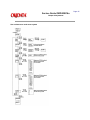
2. OPERATION DESCRIPTION
OKIPAGE16n / OKIPAGE16n/PS consists of a main control board, a power supply board, a driver
board, an operator panel and an electrophotographic process mechanism.
The control board receives data through a host I/F, decodes and edits the data, and stores the
edited data in memory. After completing edition of one page of data, it references the font memory
and generates bit data on the same memory. At the same time, it transfers the bit image data to
the LED head in units of one dot line.
The electrophotographic process mechanism prints data on paper.
The operator panel is used for operations and status display.
Fig. 2-1 shows an OKIPAGE16n / OKIPAGE16n/PS block diagram.
Copyright 1997, Okidata, Division of OKI America, Inc. All rights reserved. See the OKIDATA Business
Partner Exchange (BPX) for any updates to this material. (http://bpx.okidata.com)
Page: 9
Service Guide OKIPAGE16n
Chapter 2 Operation Description
2.1 Main Control Board (BOARD-COM)
The control board consists of an one chip CPU, LSIs, program/font ROM's, DRAM's, an EEPROM,
a host interface circuit, and a mechanism driving circuit.
(1) One-chip CPU
The one-chip CPU is a custom CPU (32-bit internal bus, 32-bit external bus, 32-MHz clock)
that incorporates an RISC CPU and its peripheral devices, and has the following functions.
Built-in device
Chip select controller
Bus controller
DRAM controller
DRAM controller
Parallel interface controller
Timer
Serial I/O port
I/O port
Option I/O interface
Function
Control of ROM, DRAM and I/O device
Transfer of image data from DRAM to OST LSI
Control of Centronics parallel interface
Generation of various control timing
Monitoring of paper running and paper size
Control of operator panel, EEPROM, and options
Inputting/outputting of sensor, signal and motor signal
Control of OKI HSP interface
(2) Program/font ROM's
The program/font ROM's store the HP IV emulation program and various types of font. MASK ROM is
used as the program/font ROM's.
(3) DRAM's
2-Megabyte DRAM (4 Mbit DRAM x 4) is mounted as resident memory to be used for storing
the program and providing various buffers. This DRAM is expandable up to 66 Mbytes by
adding expansion memory (SIMMs). This DRAM provides the areas shown in the following
table.
Memory area
Use
MENU
System area
Raster buffer
Receive buffer
Working area used for the program
Stores converted bit image data
Stores temporarily the data
received from the host interface
Adds print information to the
analyzed receive data and stores
the resulted data.
Stores soft fonts and macro data.
Fixed
Enable
Enable
Memory capacity setting
Expansion RAM
Fixed
Expandable
Expandable
-
Expandable
-
Expandable
Page buffer
DLL/macro buffer
Font cache buffer
Stores bit map fonts generated by
the font rasterizer based on
scalable font information
Enable
Expandable
(4) EEPROM
The EEPROM has a 1-kbit capacity and stores the following data.
Menu data
Various counter data (page counter, drum counter, fuser counter, etc.)
Adjustment parameters (LED head drive time, print start position, etc.)
(5) LSI (MBCE31701-040FP-BND)
This LSI is used as a peripheral device of the CPU and performs smoothing compensation
(OST) of print image data. In addition, it transfers serially bit image data for each dot line to
the LED head.
(6) Host interface
This printer has the following interfaces to the host.
Centronics bi-directional parallel interface
OKI HSP interface (Option)
LocalTalk interface (Option - PostScript Version)
The single effective interface or the automatic interface select mode can be selected using
the menu. If the busy state of the printer continues for a long time period, the buffer near-full
control releases the busy status at constant intervals even if the host side is busy so not
to cause the interface time-out at the host side.
(a) Centronics bi-directional parallel interface
This is an interface conforming to IEEE-1284 and provides either of unidirectional and
bi-directional communications according to each of the following communication modes.
Compatibility mode
Unidirectional communications from the host to the printer.
Nibble mode
This mode transmits 4-bit wide data from the printer to the host. In this mode, each
1-byte data is transferred in the form of two nibbles using ERROR, BUSY, FAULT,
and SELECT signal leads. This mode can provide the bi-directional operation in
combination with the compatibility mode.
ECP mode
This mode provides the asynchronous bi-directional interface and transmits and
receives 1-byte data using eight data signal leads under the semi-duplex control by
the host.
When the power is turned on, the compatibility mode is automatically selected. The
change to another mode from the compatibility mode is made through negotiation.
(When the BI DIRECTION is set to ENABLE in the menu, this change can be performed.)
(For the electrical/physical characteristics of this interface, see APPENDIX A)
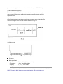
(b) OKI HSP interface (Option)
This interface (slot) is an OKI unique universal interface that provides the platform to
connect various boards (such as the LAN connection expansion board and SCSI
expansion board).
Any expansion boards compatible with this interface can be mounted on the Control
board in the piggyback board without modifying the program at the printer side. The
conceptual diagram of the OKI HSP interface is shown in Fig. 2-2.
(7) RAM module
Pin layout
Basic specification
- Type:
72 pins SIMM (32 bits buss width)
- Access time:
60ns, 70ns, 80ns, 100ns
- Capacity:
1, 2, 4, 8, 16 or 32MB
- Parity:
None
Copyright 1997, Okidata, Division of OKI America, Inc. All rights reserved. See the OKIDATA Business
Partner Exchange (BPX) for any updates to this material. (http://bpx.okidata.com)
Page: 10
Service Guide OKIPAGE16n
Chapter 2 Operation Description
2.2 Power Supply Board
The power supply board consists of an AC filter circuit, a low voltage power supply circuit, a high
voltage power supply circuit, heater drive circuit, and photosensors.
(1) Low voltage power supply circuit
This circuit generates the following voltages.
Output voltage
+5 V
+30 V
+8 V
-8 V
Use
Logic circuit supply voltage
Motor and fan drive voltage and source voltage for high-voltage supply
Reset circuit
Local Talk Line voltage
(2) High voltage power supply circuit
This circuit generates the following voltages necessary for electrophotographic processing
from +30 V according to the control sequence from the control board. When cover open state
is detected, +30 V supply is automatically interrupted to stop the supply of all the high-voltage
outputs.
Output
CH
DB
SB
TR
CB
Voltage
-1.30 KV
-240 V/+300 V
-360 V/450 V
+4 KV/-1.3 kV
+400 V
Use Remarks
Voltage applied to charging roller
Voltage applied to developing roller
Voltage applied to toner supply roller
Voltage applied to transfer roller
Voltage applied to cleaning roller
Remarks
Variable
(3) Photosensor
The photosensor mounted on this power supply board supervises the paper running state
during printing.
Sensor
Inlet sensor 1
Inlet sensor 2
Paper sensor
Outlet sensor
Paper end sensor
Toner low sensor
Function
Detects the leading part of the paper and gives
the supervision timing for switching from
hopping operation to feeding operation.
Supervises the paper running state and the
paper size according to the paper reach time
and running time.
Detects the form width.
Sensing state
ON: Paper exists.
OFF: No paper exists.
ON: A4 or larger
OFF: Smaller than A4
Detects the leading part of the paper.
ON: Paper exists.
Supervises the paper running state.
OFF: No paper exists.
Supervises the paper feed and size according to ON: Paper exists.
the time of arrival to the sensor and the time of OFF: No paper exists.
passage of paper.
Detect the end of the paper.
ON: Paper exists.
OFF: No paper exists.
Detects the lack of toner.
ON long: Toner low exists
OFF short: No Toner low exists
Copyright 1997, Okidata, Division of OKI America, Inc. All rights reserved. See the OKIDATA Business
Partner Exchange (BPX) for any updates to this material. (http://bpx.okidata.com)
Page: 11
Service Guide OKIPAGE16n
Chapter 2 Operation Description
2.3 Relay/Driver Board (AOLC board)
This board relays signals between the Control board and the Power supply board and includes
the registration motor and drum motor driver IC.
Copyright 1997, Okidata, Division of OKI America, Inc. All rights reserved. See the OKIDATA Business
Partner Exchange (BPX) for any updates to this material. (http://bpx.okidata.com)
Page: 12
Service Guide OKIPAGE16n
Chapter 2 Operation Description
2.4 Electrophotographic Process
2.4.1 Electrophotographic process mechanism (see
2.4.2 Electrophotographic process (see
2.4.3 Process operation description (see
).
).
).
Copyright 1997, Okidata, Division of OKI America, Inc. All rights reserved. See the OKIDATA Business
Partner Exchange (BPX) for any updates to this material. (http://bpx.okidata.com)
Page: 13
Service Guide OKIPAGE16n
Chapter 2 Operation Description
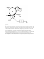
2.4.1 Electrophotographic process mechanism
This mechanism prints image data from the control board on the paper by electrophotographic
process.
The Figure 2-4 shows the layout of the electrophotographic process mechanism.
(1) Image drum unit
The image drum unit consists of a sensitive drum, a charger, and a developer. The unit forms
a toner image on the sensitive drum, using a electrostatic latent image formed by the LED
head.
(2) Hopping motor
This motor is a pulse motor of 48 steps/rotation that is two-phase excited by the signal from
the control board. It drives the hopping roller of the first tray and the front feed roller via two
one-way clutches according to the direction of rotation.
(3) Registration motor
This motor is a pulse motor of 48 steps/rotation that is two-phase excited by the signal from
the control board. It drives the registration roller.
(4) Drum motor
This drum motor is a pulse motor of 48 steps/rotation that is two-phase excited by the signal
from the control board and is the main motor of this mechanism.
(5) LED head
Image data for each dot line from the control board is received by the shift register and latch
register. The 4992 LEDs are driven to radiate the image data to the image drum.
(6) Fuser
The fuser consists of a heater, a heat roller, a thermistor and a thermostat.
An AC voltage from the power supply board is applied to the heater under the control of the
HEATON signal from the control board. This AC voltage heats the heater. The control board
supervises the heat roller temperature via the thermistor, and regulates the heater roller at
a predetermined temperature (185 ~ 188°C) by connecting or disconnecting the AC voltage
supply to the heater.
If the heater roller temperature rises abnormally, the thermostat of the heater voltage supply
circuit is activated to cut the AC voltage supply immediately.
Copyright 1997, Okidata, Division of OKI America, Inc. All rights reserved. See the OKIDATA Business
Partner Exchange (BPX) for any updates to this material. (http://bpx.okidata.com)
Page: 14
Service Guide OKIPAGE16n
Chapter 2 Operation Description
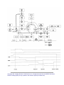
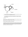
2.4.2 Electrophotographic process
The electrophotographic processing is outlined below. Figure 2-5 shows the electrophotographic
printing process.
1 Charging
The surface of the image drum is uniformly charged with negative charges by applying a
negative voltage to the charge roller.
2 Exposure
Light emitted from the LED head irradiates the negatively charged surface of the image drum.
The surface potential of the irradiated part of the image drum surface is lowered, so that an
electrostatic latent image associated with the print image is formed.
3 Developing and toner recovery
When the negatively charged toner is brought into contact with the image drum, it is attracted
to the electrostatic latent image by static electricity, making the image visible.
At the same time, the residual toner on the image drum is attracted to the developing roller
by static electricity.
4 Transfer
When paper is placed over the image drum surface and a positive charge, opposite in polarity
to the toner, is applied to the reverse side of the paper from the transfer roller, the toner is
attracted by the positive charge and is transferred to the paper. As a result, the toner image
formed on the image drum is transferred to the paper.
5 Temporary cleaning
Residual toner that remains on the image drum without being transferred is made uniform
by the cleaning roller and is temporarily attracted to the cleaning roller by static electricity.
6 Fusing
The toner image transferred to the paper is fused under heat and pressure.
Figure 2-6 shows an electrophotographic process timing chart.
Copyright 1997, Okidata, Division of OKI America, Inc. All rights reserved. See the OKIDATA Business
Partner Exchange (BPX) for any updates to this material. (http://bpx.okidata.com)
Page: 15
Service Guide OKIPAGE16n
Chapter 2 Operation Description
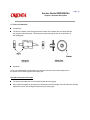
2.4.3 Process operation descriptions
(1) Hopping
Feeding from the first tray and the front feeder are effected by a single hopping motor in the
mechanism shown below.
Turning the Hopping motor in the "a" direction drives the hopping roller of the first tray.
Turning the Hopping motor in the "b" direction drives the Hopping roller of the front feeder.
Both hopping gears contain one-way bearings, so that turning each of these gears in reverse
direction will not be transmitted to the corresponding roller.
(a) Hopping (1st tray)
1. Rotating the pulse motor in the direction a (clockwise [CW] direction) drives the
hopping roller of the first tray to advance the paper until the inlet sensor turns on.
At the same time, the one-way clutch gear B also rotates. However, the hopping
roller of the front feeder will not rotate due to the one-way bearing.
2. After turning on the inlet sensor, the paper advances further by a predetermined
length until it hits the registration roller. (The skew of the paper can thus be
corrected.)
(b) Hopping (front feeder)
1. Rotating the pulse motor in the direction b (counterclockwise [CCW] direction)
drives the hopping roller of the front feeder to advance the paper until the inlet
sensor turns on. At the same time, the one-way clutch gear A also rotates.
However, the hopping roller of the 1st tray will not rotate due to the one-way bearing.
A cam to push down the front feeder plate is attached on each of the ends of the
hopping roller shaft. These cams push down the front feeder plate when the
hopping operation is not performed so as to facilitate the setting of paper into the
tray. A microswitch is provided under the front feeder plate to detect that the front
feeder plate is at the lower position. When the front feeder plate is at the lower
position, this microswitch causes the motor to stop.
2.
After turning on the inlet sensor, the paper advances further by a predetermined
length until it hits the registration roller. (The skew of the paper can thus be
corrected.)
(2) Feeding
After the end of hopping, the pulse motor dedicated for driving the registration roller rotates
to drive the registration roller. The driven registration roller advances the paper until it comes
out of the registration roller.
When the leading edge of the paper causes the paper sensor to turn on, the printing is started
synchronously.
(3) Charging
Charging is effected by applying a DC minus voltage to the charge roller that is in contact with
the image drum surface.
(4) Exposure
Light emitted from the LED head irradiates the image drum surface with negative charges.
The surface potential of the irradiated part of the image drum drops, thereby forming an
electrostatic latent image associated with the image signal.
(5) Developing
Toner is attracted to the electrostatic latent image on the image drum surface to convert it
into a visible toner image. Developing takes place at the contact between the image drum
and the developing roller.
1. 1 As the toner supply roller rotates while rubbing on the developing roller, a friction charge
is generated between the developing roller and the toner, allowing the toner to be
attracted to the developing roller. (The developing roller surface is charged positive and
the toner, negative.)
2.
The toner attracted to the developing roller is scraped off by the doctor blade, forming
a thin coat of toner on the developing roller surface.
3.
Toner is attracted to the exposed part (low-potential part) of the image drum at the
contact between the image drum and the developing roller, making the electrostatic
latent image visible.
(6) Transfer
The transfer roller is composed of conductive sponge material and is designed to make the
image drum surface and the paper closely into contact.
Paper is placed over the image drum surface, and a positive charge, opposite in polarity to
the toner, is applied to the paper from its reverse side.
The application of a high positive voltage from the power supply to the transfer roller causes
the positive charge induced to the transfer roller surface to be transferred to the paper at the
contact between the transfer roller and the paper. As a results, toner charged negative that
is attracted to the image drum surface is transferred to the upper side of the paper by the
positive charge on the lower side of the paper.
(7) Fusing
After the end of the transfer, the unfused toner image is fused on the paper under heat and
pressure as it passes between the heater roller and the backup roller. The heater roller with
a Teflon coating incorporates a 400W heater (Halogen lamp), which heats the heat roller.
A thermistor which is in contact with the heater roller regulates the heater roller at a
predetermined temperature (about 185 ~ 188°C). A safety thermostat cuts off voltage supply
to the heater by opening the thermostat in the event of abnormal temperature rises.
The backup roller is held under a pressure of 2.5 kg from the pressure spring at each side.
(8) Cleaning
After the end of the transfer, residual toner on the image drum is attracted to the cleaning
roller temporarily by static electricity to clean the image drum surface.
(9) Cleaning of rollers
The charge roller, transfer roller and cleaning roller are cleaned in the following cases:
In warming up at power-on time
In warming up after the cover is opened and closed
When the number of accumulated sheets is 10 or more and the printout operation ends
Changes in bias voltage applied to each roller move adhesive toner from the roller to the
image drum and return it to the developer.
Copyright 1997, Okidata, Division of OKI America, Inc. All rights reserved. See the OKIDATA Business
Partner Exchange (BPX) for any updates to this material. (http://bpx.okidata.com)
Page: 16
Service Guide OKIPAGE16n
Chapter 2 Operation Description
2.5 Paper Jam Detection
The paper jam detection function supervises the paper state at power-on time and during printing.
In the event that the following state occurs, this function interrupts the printing process. If any of
the following errors is presented, recovery printing will be performed by removing the jammed
paper (namely by opening the upper cover, removing the jammed paper and closing the upper
cover).
Error
Paper input jam
Paper feed jam
Paper exit jam
Paper size error
Cause of error
- At power-on time, the paper is placed at the inlet sensor.
- After hopping operation is attempted three times, the leading part of the
paper does not reach the inlet sensor.
- At power-on time, the paper is placed at the paper sensor.
- The leading part of the paper does not reach the paper sensor within a
predetermined distance after the paper has reached the inlet sensor.
- The trailing part of the paper does not pass over the paper sensor within a
predetermined distance after the leading edge of the paper has passed over
the paper sensor.
- The leading part of paper does not reach the outlet sensor within a
predetermined distance after the paper has reached the paper sensor.
- At power-on time, the paper is placed on the outlet sensor.
- The paper does not pass over the outlet sensor within a predetermined time
after the leading part of the paper has reached the outlet sensor.
- The paper size check with the manual feed specified considers the
reference size as free size.
- The size of the paper is supervised by the inlet sensors 1. It is detected that
the paper does not pass over the inlet sensor 1 within predetermined range of
distance.
- The inlet sensor 2 detects that the size of the loaded paper is A4 or larger, or
smaller than A4. The detected paper size differs from the paper size set by
command or menu.
- The paper size check with the manual feed specified considers the
reference size as free size.
Copyright 1997, Okidata, Division of OKI America, Inc. All rights reserved. See the OKIDATA Business
Partner Exchange (BPX) for any updates to this material. (http://bpx.okidata.com)
Page: 17
Service Guide OKIPAGE16n
Chapter 2 Operation Description
2.6 Cover Open
When the stacker cover is opened, the cover open microswitch on the power supply board is
turned off to cut the supply of +30V to the high voltage power supply circuit. As a result, all high-voltage
outputs are interrupted. At the same time, the CVOPN signal is sent to the control board to notify it of the
off state of the microswitch, and the control board performs the cover open
processing.
Copyright 1997, Okidata, Division of OKI America, Inc. All rights reserved. See the OKIDATA Business
Partner Exchange (BPX) for any updates to this material. (http://bpx.okidata.com)
Page: 18
Service Guide OKIPAGE16n
Chapter 2 Operation Description
2.7 Toner Low Detection
Composition
The device consists of the stirring gear which rotates at a constant rate, the stirring bar and
the magnet on the stirring bar. The stirring bar rotates through the link on the protrusion in
the stirring gear.
Operation
Toner Low is detected by monitoring the time interval of the encounter of the magnet set on
the sensor lever and the magnet on the stirring bar.
Operation during toner full state
The stirring bar rotates due to the interlocking with the stirring gear.
Even when the magnet on the stirring bar reaches the maximum height, since the other side is being
dipped in the toner, the stirring bar is pushed by the stirring gear.
Operation during toner low state
When the stirring bar reaches the maximum height, since there is no resistance provided
by the toner on the other side, it falls to the minimum height due to its own weight. Because
of this, the time interval during which it encounters the magnet of the sensor lever becomes long. By
monitoring this time interval, toner low can be detected.
When the toner low state is detected 2 times consecutively, Toner Low is established.
When the toner full state is detected 2 times consecutively, Toner Low is canceled.
When there is no change with the toner sensor for 2 cycles (3.398 sec. x 2) or more, then the
Toner Sensor Alarm is activated.
The toner sensor is not monitored while the drum motor is stopped.
Copyright 1997, Okidata, Division of OKI America, Inc. All rights reserved. See the OKIDATA Business
Partner Exchange (BPX) for any updates to this material. (http://bpx.okidata.com)
Page: 19
Service Guide OKIPAGE16n
Chapter 2 Operation Description
2.8 Stacker-full Detection
The sensor (interlocked with the lever) at the paper outlet to the stacker detects a stacker-full state
(about 250 sheets) and stops printing of the ensuing pages.
Copyright 1997, Okidata, Division of OKI America, Inc. All rights reserved. See the OKIDATA Business
Partner Exchange (BPX) for any updates to this material. (http://bpx.okidata.com)
Page: 20
Service Guide OKIPAGE16n
Chapter 2 Operation Description
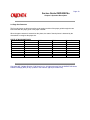
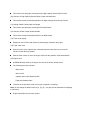
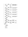
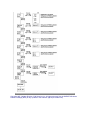
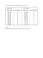
2.9 Page Size Detection
The four tab pieces are driven according to the setting position of the paper guide through the cam
interlocked with the paper guide of the paper cassette.
When the paper cassette is inserted into the printer, the state of the tab pieces is detected by the
microswitch to recognize the paper size.
STATE OF MICROSWITCHES
SW2
SW1
0
1
0
1
0
0
1
1
1
0
1
1
1
1
1
0
SW3
1
0
1
1
1
0
0
0
SW4
1
1
1
0
1
1
0
1
Paper size
Letter
Executive
A4
Legal 14
Legal 13
B5
A5
A6
Copyright 1997, Okidata, Division of OKI America, Inc. All rights reserved. See the OKIDATA Business
Partner Exchange (BPX) for any updates to this material. (http://bpx.okidata.com)
Page: 21
Service Guide OKIPAGE16n
Chapter 2 Operation Description
2.10 PostScript Board (BOARD-PSBA) Optional
The PostScript board consists of program/font ROM's, an EEPROM, and a LocalTalk interface
control circuit.
(1) Program/font ROM's
The program/font ROM's store the PostScript Level II program and its fonts.
MASK ROM is used as the program/font ROM's.
(2) EEPROM
The EEPROM has a 4-kbit capacity and stores the PostScript's menu settings.
(3) LocalTalk interface control circuit
AppleTalk protocol data is received from the host system via LocalTalk interface.
The LocalTalk interface control circuit consists of a CPU, a program ROM, a SRAM, and a
driver/receiver IC.
Copyright 1997, Okidata, Division of OKI America, Inc. All rights reserved. See the OKIDATA Business
Partner Exchange (BPX) for any updates to this material. (http://bpx.okidata.com)
Page: 22
Service Guide OKIPAGE16n
Chapter 3 Parts Replacement
3. PARTS REPLACEMENT
The section explains the procedures for replacement of parts, assemblies, and units in the field.
Only the removal procedures are explained here. Reverse the procedure for the installation.
Copyright 1997, Okidata, Division of OKI America, Inc. All rights reserved. See the OKIDATA Business
Partner Exchange (BPX) for any updates to this material. (http://bpx.okidata.com)
Page: 23
Service Guide OKIPAGE16n
Chapter 3 Parts Replacement
3.1 Precautions for Parts Replacement
(1) Before starting parts replacement, remove the AC cable and interface cable.
(a) Remove the AC cable in the following procedure:
i) Turn off ("o") the power switch of the printer
ii) Disconnect the AC inlet plug of the AC cable from the AC receptacle.
iii) Disconnect the AC cable and interface cable from the printer.
(b) Reconnect the printer in the following procedure.
i) Connect the AC cable and interface cable to the printer.
ii) Connect the AC inlet plug to the AC receptacle.
iii) Turn on ("l") the power switch of the printer.
##
(2) Do not try disassembly as long as the printer is operating normally.
(3) Do not remove unnecessary parts: try to keep disassembly to a minimum.
(4) Use specified service tools.
(5) When disassembling, follow the determined sequence. Otherwise, parts may be damaged.
(6) Since screws, collars and other small parts are likely to be lost, they should temporarily be
attached to the orginal positions.
(7) When handling ICs such as microprocessors, ROM and RAM, and circuit boards, do not wear
gloves that are likely to generate static electricity.
(8) Do not place printed circuit boards directly on the equipment or floor.
[Service Tools]
Table 3-1 shows the tools required for field replacement of printed circuit boards and units.
Table 3-1 Service Tools
XX
Copyright 1997, Okidata, Division of OKI America, Inc. All rights reserved. See the OKIDATA Business
Partner Exchange (BPX) for any updates to this material. (http://bpx.okidata.com)
Page: 24
Service Guide OKIPAGE16n
Chapter 3 Parts Replacement
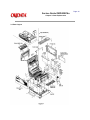
3.2 Parts Layout
Figure 3-2
Copyright 1997, Okidata, Division of OKI America, Inc. All rights reserved. See the OKIDATA Business
Partner Exchange (BPX) for any updates to this material. (http://bpx.okidata.com)
Page: 25
Service Guide OKIPAGE16n
Chapter 3 Parts Replacement
3.3 How to Change Parts
This section explains how to change parts and assemblies appearing in the disassembly diagram below.
Copyright 1997, Okidata, Division of OKI America, Inc. All rights reserved. See the OKIDATA Business
Partner Exchange (BPX) for any updates to this material. (http://bpx.okidata.com)
Page: 26
Service Guide OKIPAGE16n
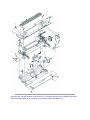
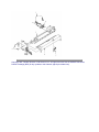
Chapter 3 Parts Replacement
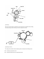
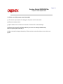
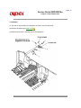
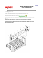
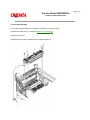
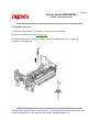
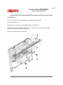
3.3.1 Rear cover, side cover (L) Assembly, face-up stacker Assembly, and I/F cover Assembly.
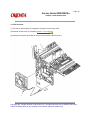
(1) Turn the AC power switch off. Unplug the AC power cord from the outlet.
(2) Remove the interface cable 1. Remove drum/toner Assembly (see picture below) and store in black
plastic bag shipped w/printer.
(3) Open the face-up stacker Assembly 8. Disconnect the engagement at the left and right
protrusions 8A . Remove the face-up stacker Assembly 8. (Flex the Assembly 8 in the
middle to disengage 8A from the Rear cover 0.)
(4) Open the stacker cover 2 and the manual feed hopper Assembly3. Remove three screws
4. Remove the side cover (L) Assembly 5.
(5) Remove two screws 6. Remove the I/F cover Assembly 7.
(6) Remove two screws 9 and four claws A. (Use a small flat blade screw driver to "pop" claws.)
Remove the rear cover 10.
Copyright 1997, Okidata, Division of OKI America, Inc. All rights reserved. See the OKIDATA Business
Partner Exchange (BPX) for any updates to this material. (http://bpx.okidata.com)
Page: 27
Service Guide OKIPAGE16n
Chapter 3 Parts Replacement
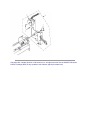
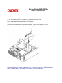
3.3.2 Contact Assembly
(1) Turn the AC power switch off. Unplug the AC power cord from the outlet.
(2) Remove the side cover (L) Assembly (see 3.3.1 (1) to (4)).
(3) Remove two screws 1. Remove the contact plate (cover) 2 and the contact Assembly 3. Pull
bottom of Assembly 3 out first, then the top of Assembly. Remove fan connector cables from
location 4.
Caution: Be careful not to deform the electrodes of the contact Assembly when removing
the contact Assembly.
Copyright 1997, Okidata, Division of OKI America, Inc. All rights reserved. See the OKIDATA Business
Partner Exchange (BPX) for any updates to this material. (http://bpx.okidata.com)
Page: 28
Service Guide OKIPAGE16n
Chapter 3 Parts Replacement
3.3.3 DC fan motor
(1) Turn the AC power switch off. Unplug the AC power cord from the outlet.
(2) Remove the side cover (L) Assembly (see 3.3.1 (1) to (4)).
(3) Unplug the connector of the DC fan motor 1 and remove the DC fan motor 1.
Copyright 1997, Okidata, Division of OKI America, Inc. All rights reserved. See the OKIDATA Business
Partner Exchange (BPX) for any updates to this material. (http://bpx.okidata.com)
Page: 29
Service Guide OKIPAGE16n
Chapter 3 Parts Replacement
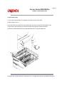
3.3.4 Manual feed hopper Assembly
(1) Turn the AC power switch off. Unplug the AC power cord from the outlet.
(2) Open manual feed hopper Assembly 1. Disengage the lower portion of this Assembly.
(3) Hold manual feed hopper Assembly 1 vertically and remove the left and right levers 2 with
a downward motion.
Copyright 1997, Okidata, Division of OKI America, Inc. All rights reserved. See the OKIDATA Business
Partner Exchange (BPX) for any updates to this material. (http://bpx.okidata.com)
Page: 30
Service Guide OKIPAGE16n
Chapter 3 Parts Replacement
3.3.5 Side cover (R) (operator panel Assembly)
(1) Turn the AC power switch off. Unplug the AC power cord from the outlet.
(2) Remove interface cable 1.
(3) Open stacker cover 2. Remove two screws 3. Remove I/F cover Assembly 4.
(4) Remove two screws 5 and flexible cable 6 (use care to not damage flexible cable).
Remove operator panel Assembly 7.
(5) Open manual feed hopper Assembly 8. Remove three screws 9 and then remove side cover
(R) 10.
Copyright 1997, Okidata, Division of OKI America, Inc. All rights reserved. See the OKIDATA Business
Partner Exchange (BPX) for any updates to this material. (http://bpx.okidata.com)
Page: 31
Service Guide OKIPAGE16n
Chapter 3 Parts Replacement
3.3.6 Earth plate BK (R) (BOARD-PSBA, BOARD-COM)
(1) Turn the AC power switch off. Unplug the AC power cord from the outlet.
(2) Remove side cover (R) (see 3.3.5).
(3) Remove a screw 1. Remove BOARD-PSBA 2. (OKIPAGE16n/PS only)
(4) Remove five screws 3 and seven connectors 4. Remove BOARD-COM 5.
(5) Remove two screws 6 Remove IC card cover 7.
(6) Remove four screws 8. Remove side plate (R) 9, by pulling up and out on top part of plate.
(7) Remove the claws and then remove Earth plate BK (R) 10.
Copyright 1997, Okidata, Division of OKI America, Inc. All rights reserved. See the OKIDATA Business
Partner Exchange (BPX) for any updates to this material. (http://bpx.okidata.com)
Page: 32
Service Guide OKIPAGE16n
Chapter 3 Parts Replacement
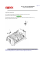
3.3.7 Stacker cover Assembly, damper arm, and washer
(1) Turn the AC power switch off. Unplug the AC power cord from the outlet.
(2) Remove the rear cover (see 3.3.1).
(3) Remove the side cover (R) (see 3.3.5).
(4) Remove the side plate (R) (see 3.3.6 (1) to (6)).
(5) Disconnect the engagement of backup release lever 1 with the protrusion on the light side
surface on the right side of the stacker cover.
(6) Remove screw 2 and washer 3. Remove two claws. Remove stacker cover Assembly 4 (at
this time, the damper arm 5 is also removed).
Copyright 1997, Okidata, Division of OKI America, Inc. All rights reserved. See the OKIDATA Business
Partner Exchange (BPX) for any updates to this material. (http://bpx.okidata.com)
Page: 33
Service Guide OKIPAGE16n
Chapter 3 Parts Replacement
3.3.8 Damper
(1) Turn the AC power switch off. Unplug the AC power cord from the outlet.
(2) Remove the damper arm (see 3.3.7).
(3) Remove two screws 1 and then remove two dampers 2.
Copyright 1997, Okidata, Division of OKI America, Inc. All rights reserved. See the OKIDATA Business
Partner Exchange (BPX) for any updates to this material. (http://bpx.okidata.com)
Page: 34
Service Guide OKIPAGE16n
Chapter 3 Parts Replacement
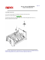
3.3.9 Stacker full sensor Assembly
(1) Turn the AC power switch off. Unplug the AC power cord from the outlet.
(2) Remove the stacker cover Assembly (see 3.3.7).
(3) Remove four screw 1. Remove stacker mount 2 by releasing the tabs at position 2A .
(4) Remove stacker full sensor Assembly 3 by releasing spreading the plastic tabs on each side
of sensor Assembly 3 and lifting switch from cover.
Copyright 1997, Okidata, Division of OKI America, Inc. All rights reserved. See the OKIDATA Business
Partner Exchange (BPX) for any updates to this material. (http://bpx.okidata.com)
Page: 35
Service Guide OKIPAGE16n
Chapter 3 Parts Replacement
3.3.10 Cable cover (cable guides A and B)
(1) Turn the AC power switch off. Unplug the AC power cord from the outlet.
(2) Remove the stacker cover Assembly (see 3.3.7
).
(3) Remove two screws 1 release tabs at position 1A . Remove cable cover 2, cable guide A
3.
Note: Use care when replacing cable cover. Do not pinch, crimp, or cut cables or protective sheet.
Copyright 1997, Okidata, Division of OKI America, Inc. All rights reserved. See the OKIDATA Business
Partner Exchange (BPX) for any updates to this material. (http://bpx.okidata.com)
Page: 36
Service Guide OKIPAGE16n
Chapter 3 Parts Replacement
3.3.11 Eject roller Assembly
(1) Turn the AC power switch off. Unplug the AC power cord from the outlet.
(2) Remove the rear cover (see 3.3.1
).
(3) Remove the side cover (R) (see 3.3.5
).
(4) Remove the side plate (R) (see 3.3.6 (1) to (6)
(5) Remove the stacker cover Assembly (see 3.3.7
).
).
(6) Release the latch on the right side of eject roller Assembly 1. Lift up and remove the eject
roller Assembly.
Copyright 1997, Okidata, Division of OKI America, Inc. All rights reserved. See the OKIDATA Business
Partner Exchange (BPX) for any updates to this material. (http://bpx.okidata.com)
Page: 37
Service Guide OKIPAGE16n
Chapter 3 Parts Replacement
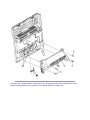
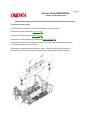
3.3.12 Paper supply guide D
(1) Turn the AC power switch off. Unplug the AC power cord from the outlet.
(2) Remove the side cover (R) (see 3.3.5).
(3) Remove five screws 1. Lift up and remove front feeder roller Assembly 2.
(4) Lift up and remove paper supply guide D 3. (At this time, two bias rollers 4 and bias spring
5 are also removed. Be careful not to lose them.)
Copyright 1997, Okidata, Division of OKI America, Inc. All rights reserved. See the OKIDATA Business
Partner Exchange (BPX) for any updates to this material. (http://bpx.okidata.com)
Page: 38
Service Guide OKIPAGE16n
Chapter 3 Parts Replacement
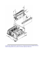
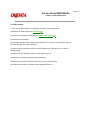
3.3.13 Separator F
(1) Turn the AC power switch off. Unplug the AC power cord from the outlet.
(2) Remove the manual feed hopper Assembly (see 3.3.4
(3) Remove the side cover (R) (see 3.3.5
).
).
(4) Remove the front feeder Assembly (see 3.3.12 steps (1) to (3)
and routing.
) . Make a diagram of wire locations
(5) Remove two screws 1 and then remove the inner cover 2. At this time, the cover lock lever
3 and the torsion spring 4 are also removed, note position of torsion spring.
(6) Remove two screws 5 and then remove square-shaped connector 6.
(7) Using a dedicated tool, remove the connector of switch Assembly 7 from square-shaped
connector 6.
(8) Turn idle gear 8 in the direction of arrow A until front feeder plate 9 is elevated.
(9) Remove front feeder gear = and then remove two springs (F) A. Be careful not to lose the
springs.
(10) Remove four screws B and then remove paper supply guide A C. (At this time, front feeder
earth plate D G H are also removed.)
(11) Remove front feeder plate 9 by releasing the engagement at two parts 9A .
Switch Assembly 7 may now be removed.
(12) Pull up separator E toward you and then release two mounting posts at 15A to remove the
separator. (At this time, two springs F are also removed simultaneously. Be careful not to
lose the springs.)
(13) Release two clutches on paper supply guide C and pull out switch Assembly 7 upward.
Switch Assembly 7 should be moved more towards the center of the paper path.
During Re-assembly use great care: do not pinch, crimp, or cut wires to switch Assembly 7.
Copyright 1997, Okidata, Division of OKI America, Inc. All rights reserved. See the OKIDATA Business
Partner Exchange (BPX) for any updates to this material. (http://bpx.okidata.com)
Page: 39
Service Guide OKIPAGE16n
Chapter 3 Parts Replacement
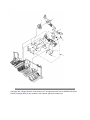
3.3.14 Front feeder roller Assy
(1) Turn the AC power supply switch off. Unplug the AC power cord from the outlet.
(2) Remove the manual feed hopper Assy (see 3.3.4 .
(3) Remove the side cover (R) (see 3.3.5
).
).
(4) Remove the front feeder roller Assy (see 3.3.12 (1) to (3)
.
(5) Remove the paper supply guide A (see 3.3.13 (1) to (10))
.
(6) Remove idle gear 1 and then remove the right side front feeder cam 2, release lever (R)
3, and spring 4. (At this time, knock pin 5 and bearing F 6 are also removed. Be careful
not to lose them.) Do not mix these parts with those from the left side of Assy.
(7) Pull out the front feeder shaft 7 toward the left and then remove front feeder roller Assy 8.
(8) Remove knock pin 9 and then remove front feeder cam = on the left (L) side, release lever
(L) A, and spring B. (At this time, the bearing F C on the left (L) side is also removed.) Do
not mix these parts with those from the right side of Assy.
Note:
1: Hopping roller orientation when removed from shaft.
2: Be sure sensor arm swings freely after re-assembly.
3: Be sure that during re-assembly both feeder cams (2 and =) are facing the same
direction.
Copyright 1997, Okidata, Division of OKI America, Inc. All rights reserved. See the OKIDATA Business
Partner Exchange (BPX) for any updates to this material. (http://bpx.okidata.com)
Page: 40
Service Guide OKIPAGE16n
Chapter 3 Parts Replacement
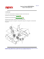
3.3.15 Hopping motor
(1) Turn the AC power switch off. Unplug the AC power cable from the outlet.
(2) Remove the manual feed hopper Assembly (see 3.3.4
(3) Remove the side cover (R) (see 3.3.5
).
).
(4) Remove the front feeder Assembly (see 3.3.12.(1) to (3)
).
(5) Remove the inner cover and square-shaped connector (see 3.3.13.(5) and (6)
).
(6) Using a dedicated tool, remove the connector of hopping motor 1 from the square-shaped
connector.
(7) Remove the paper supply guide A (see 3.3.13. (7) to (10)
(8) Remove the lever (R) (see 3.3.10. (6)
).
).
(9) Remove two screws 2 and then remove side plate (R) Assembly 3.
(10) Remove two screws 4 and then remove hopping motor 1.
Copyright 1997, Okidata, Division of OKI America, Inc. All rights reserved. See the OKIDATA Business
Partner Exchange (BPX) for any updates to this material. (http://bpx.okidata.com)
Page: 41
Service Guide OKIPAGE16n
Chapter 3 Parts Replacement
3.3.16 Front feeder paper end sensor
(1) Turn the AC power switch off. Unplug the AC power cord from the outlet.
(2) Remove the manual feed hopper Assembly (see 3.3.4
(3) Remove the side cover (R) (see 3.3.5
).
).
(4) Remove the front feeder roller Assembly (see 3.3.12. (1) to (3)
(5) Remove the side plate (R) Assembly (see 3.3.15. (1) to (9)
).
).
(6) Using a dedicated tool, remove the connector of front feeder paper end sensor 1 from the
square-shaped connector.
(7) Remove two screws 2 and then remove paper supply guide C 3.
(8) Remove paper supply guide B 4.
(9) Remove four claws and then remove front feeder paper end sensor 1.
(10) Remove two screws 5 and then remove square-shaped connector 6 from paper supply
guide C 3.
(11) Using a dedicated tool, remove the connector cord 7 from the square-shaped connector.
Copyright 1997, Okidata, Division of OKI America, Inc. All rights reserved. See the OKIDATA Business
Partner Exchange (BPX) for any updates to this material. (http://bpx.okidata.com)
Page: 42
Service Guide OKIPAGE16n
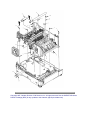
Chapter 3 Parts Replacement
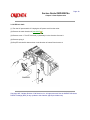
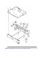
3.3.17 Main chassis unit
(1) Turn the AC power switch off. Unplug the AC power cord from the outlet.
(2) Remove the rear cover (see 3.3.1
).
(3) Remove the contact Assembly (see 3.3.2
(4) Remove the side cover (R) (see 3.3.5
).
).
(5) Remove the side plate (R) (see 3.3.6 (1) to (6)
(6) Remove the stacker cover Assembly (see 3.3.7
).
).
).
(7) Remove the front feeder roller Assembly (see 3.3.12, (1) to (3)
At this time, it is not required to remove the manual feed hopper Assembly.
(8) Remove the earth plate (HP).
(9) Lift gear (TR) 1 to unlock it. Remove gear (TR) 1 and transfer roller 2. (At this time, two
bearings (TR) 3 and two transfer springs 4 are also removed.)
Do not lose bearings or springs.
(10) Remove connector cover 5 in direction of arrow and then remove four connectors 6 and
7.
(11) Remove the DC Fan motor.
(12) Remove eight screws = and then remove main chassis unit A.
Copyright 1997, Okidata, Division of OKI America, Inc. All rights reserved. See the OKIDATA Business
Partner Exchange (BPX) for any updates to this material. (http://bpx.okidata.com)
Page: 43
Service Guide OKIPAGE16n
Chapter 3 Parts Replacement
3.3.18 Registration roller
(1) Turn the AC power switch off. Unplug the AC power cord from the outlet.
(2) Remove the front feeder roller Assembly (see 3.3.12. (1) to (3)
).
(3) Remove four screws 1. Lift and remove the registration roller Assembly 2, left side first then
right side.
(4) Release the latch and remove registration roller gear 3 and pressure roller gear 4.
(5) Remove left and right side registration roller bearing Assemblies 5 and then remove resist
roller 6 and pressure roller 7.
Copyright 1997, Okidata, Division of OKI America, Inc. All rights reserved. See the OKIDATA Business
Partner Exchange (BPX) for any updates to this material. (http://bpx.okidata.com)
Page: 44
Service Guide OKIPAGE16n
Chapter 3 Parts Replacement
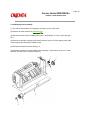
3.3.19 Drum motor
(1) Turn the AC power switch off. Unplug the AC power cord from the outlet.
(2) Remove the main chassis unit (see 3.3.17
).
(3) Remove the registration roller Assembly (see 3.3.18 (1) to (3)
).
(4) Remove fuser Assembly.
(5) Release the latch of fuser pressure roller release lever 1 and pull out it toward the right. (At
this time, idle gear H 2 is also removed.)
(6) Remove spring 3 and then remove pressure release lever 4. Be careful, do not lose or
damage spring.
(7) Remove EP lock spring 5 and then remove ED lock lever 6.
(8) Release two latches and remove motor Assembly 7.
(9) Remove two screws 8 and then remove drum motor 9 and heat sink.
(10) Remove two screws = and then remove registration motor A.
Copyright 1997, Okidata, Division of OKI America, Inc. All rights reserved. See the OKIDATA Business
Partner Exchange (BPX) for any updates to this material. (http://bpx.okidata.com)
Page: 45
Service Guide OKIPAGE16n
Chapter 3 Parts Replacement
3.3.20 Idle gear
(1) Turn the AC power switch off. Unplug the AC power cord from the outlet.
(2) Remove the main chassis unit (see 3.3.17
).
(3) Remove the motor Assembly (see 3.3.19 (1) to (8)
).
(4) Remove three screws 1 and then remove motor bracket B 2.
(5) Remove idler gear E 3, idle gear D 4, idle gear B 5, idle gear C 6, idle gear A 7, and two resist
idle gears 8.
Copyright 1997, Okidata, Division of OKI America, Inc. All rights reserved. See the OKIDATA Business
Partner Exchange (BPX) for any updates to this material. (http://bpx.okidata.com)
Page: 46
Service Guide OKIPAGE16n
Chapter 3 Parts Replacement
3.3.21 Fusing Assembly
(1) Turn the AC power switch off. Unplug the AC power cord from the outlet.
(2) Remove the side cover (L) Assembly (see 3.3.1 (1) to (3)
(3) Unplug connector 1.
(4) Remove four screws 2 and then remove fusing Assembly 3.
).
Copyright 1997, Okidata, Division of OKI America, Inc. All rights reserved. See the OKIDATA Business
Partner Exchange (BPX) for any updates to this material. (http://bpx.okidata.com)
Page: 47
Service Guide OKIPAGE16n
Chapter 3 Parts Replacement
3.3.22 Fuser pressure roller
(1) Turn the AC power switch off. Unplug the AC power cord from the outlet.
(2) Remove the main chassis unit (see 3.3.17
(3) Remove the fusing Assembly (see 3.3.21
).
).
(4) Remove the fuser pressure roller release lever (see 3.3.19 (5)
).
(5) Remove two screws 2 and release three locks on the fusing guide. Remove the fusing guide
1 by pushing it upward from the lower side.
(6) Release the engagement with earth plate L (BK) 3. Lift and remove fuser pressure roller 4.
(At this time, two fuser pressure roller bearings 5 and two bias springs 6 are also removed.)
Copyright 1997, Okidata, Division of OKI America, Inc. All rights reserved. See the OKIDATA Business
Partner Exchange (BPX) for any updates to this material. (http://bpx.okidata.com)
Page: 48
Service Guide OKIPAGE16n
Chapter 3 Parts Replacement
3.3.23 EP lock shaft
(1) Turn the AC power switch off. Unplug the AC power cord from the outlet.
(2) Remove the main chassis unit (see 3.3.17
).
(3) Remove screw 1. Turn EP lock level (L) Assembly 2 in the direction of arrow A .
(4) Remove spring 3.
(5) Drop EP lock shaft 4 down and turn in the direction of arrows B and remove it.
Copyright 1997, Okidata, Division of OKI America, Inc. All rights reserved. See the OKIDATA Business
Partner Exchange (BPX) for any updates to this material. (http://bpx.okidata.com)
Page: 49
Service Guide OKIPAGE16n
Chapter 3 Parts Replacement
3.3.24 Hopping roller Assembly
(1) Turn the AC power switch off. Unplug the AC power cord from the outlet.
(2) Remove the main chassis unit (see 3.3.17
).
(3) Release the latch. Remove hopping roller gear 1 and bearing P 2. Then, remove idle gear
HF 3.
(4) Remove the left side of hopping roller shaft 4 from the groove. Pull out hopping roller shaft
4 and hopping roller Assembly 5 toward the left..
(5) Release the latch and remove bearing L 6.
(6) Release the latch and remove hopping roller Assembly 5. (At this time, knock pin 7 is also
removed. Be careful not to lose the knock pin.)
Copyright 1997, Okidata, Division of OKI America, Inc. All rights reserved. See the OKIDATA Business
Partner Exchange (BPX) for any updates to this material. (http://bpx.okidata.com)
Page: 50
Service Guide OKIPAGE16n
Chapter 3 Parts Replacement
3.3.25 Outlet sensor lever
(1) Turn the AC power switch off. Unplug the AC power cord from the outlet.
(2) Remove the main chassis unit (see 3.3.17
).
(3) Press the clamp part of outlet sensor lever 1. Remove the outlet sensor lever 1 by pushing
it upward from the lower side.
Copyright 1997, Okidata, Division of OKI America, Inc. All rights reserved. See the OKIDATA Business
Partner Exchange (BPX) for any updates to this material. (http://bpx.okidata.com)
Page: 51
Service Guide OKIPAGE16n
Chapter 3 Parts Replacement
3.3.26 Toner sensor lever
(1) Turn the AC power switch off. Unplug the AC power cord from the outlet.
(2) Remove the main chassis unit (see 3.3.17
).
(3) Squeeze the clamp part of toner sensor lever 1 and remove the toner sensor lever 1 by
pushing it upward from the lower side.
Copyright 1997, Okidata, Division of OKI America, Inc. All rights reserved. See the OKIDATA Business
Partner Exchange (BPX) for any updates to this material. (http://bpx.okidata.com)
Page: 52
Service Guide OKIPAGE16n
Chapter 3 Parts Replacement
3.2.27 Paper sensor lever
(1) Turn the AC power switch off. Unplug the AC power cord from the outlet.
(2) Remove the main chassis unit (see 3.3.17
).
(3) Squeeze the clamp part of the paper sensor lever 1. Remove the paper sensor lever 1 by
pushing it upward from the lower side.
Copyright 1997, Okidata, Division of OKI America, Inc. All rights reserved. See the OKIDATA Business
Partner Exchange (BPX) for any updates to this material. (http://bpx.okidata.com)
Page: 53
Service Guide OKIPAGE16n
Chapter 3 Parts Replacement
3.3.28 Inlet sensor lever
(1) Turn the AC power switch off. Unplug the AC power cord from the outlet.
(2) Remove the main chassis unit (see 3.3.17
).
(3) Squeeze the clamp part of two inlet sensor levers 1. Remove the inlet sensor levers 1 by
pushing them downward.
Copyright 1997, Okidata, Division of OKI America, Inc. All rights reserved. See the OKIDATA Business
Partner Exchange (BPX) for any updates to this material. (http://bpx.okidata.com)
Page: 54
Service Guide OKIPAGE16n
Chapter 3 Parts Replacement
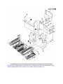
3.3.29 Power Supply Board / Insulator
(1) Turn the AC power switch off. Unplug the AC power cord from the outlet.
(2) Remove the main chassis unit (see 3.3.17
).
(3) Remove two screws 1 and then remove inlet holder 2. At this time, remove inlet 3 from inlet
holder 2.
(4) Remove eight screws 4, connector 5, and two screws 6. Remove Power Supply Board 7
together with AOLC-PCB 8.
(5) Unplug connector 9 and remove PowerSupply Board 7.
(6) Remove insulator 10.
Caution: Be careful not to deform the paper end lever A.
Copyright 1997, Okidata, Division of OKI America, Inc. All rights reserved. See the OKIDATA Business
Partner Exchange (BPX) for any updates to this material. (http://bpx.okidata.com)
Page: 55
Service Guide OKIPAGE16n
Chapter 3 Parts Replacement
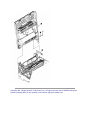
3.3.30 Paper end lever
(1) Turn the AC power switch off. Unplug the AC power cord from the outlet.
(2) Remove the main chassis unit (see 3.3.17
).
(3) Release the lock and remove paper end lever 1.
Copyright 1997, Okidata, Division of OKI America, Inc. All rights reserved. See the OKIDATA Business
Partner Exchange (BPX) for any updates to this material. (http://bpx.okidata.com)
Page: 56
Service Guide OKIPAGE16n
Chapter 3 Parts Replacement
3.3.31 Guide rail (L) Assembly
(1) Turn the AC power switch off. Unplug the AC power cord from the outlet.
(2) Remove the main chassis unit (see 3.3.17
(3) Remove the insulator (see 3.3.29
).
).
(4) Remove screw 1 and then remove base plate 2.
(5) Remove two screws 3 and then remove guide rail (L) Assembly 4.
(6) Remove cassette lock spring 5 and then remove bias link 6 and pull block 7.
(Pay attention the direction of hook of cassette lock spring 5.)
(7) Remove spring 8 and then remove cassette stopper 9.
(8) Remove screw 0 from bias link 6 and then remove link support A.
Copyright 1997, Okidata, Division of OKI America, Inc. All rights reserved. See the OKIDATA Business
Partner Exchange (BPX) for any updates to this material. (http://bpx.okidata.com)
Page: 57
Service Guide OKIPAGE16n
Chapter 3 Parts Replacement
3.3.32 Guide rail (R) Assembly
(1) Turn the AC power switch off. Unplug the AC power cord from the outlet.
(2) Remove the main chassis unit (see 3.3.17
(3) Remove the insulator (see 3.3.29
).
).
(4) Remove screw 1 and then remove base plate 2.
(5) Remove two screws 3 and then remove guide rail (R) Assembly 4.
(6) Remove cassette lock spring 5 and then remove bias link 6 and pull block 7 (At this time, earth plate 8
is also removed.)
(Pay attention the direction of hook of cassette lock spring 5.)
(7) Remove spring 9 and then remove cassette stopper =.
(8) Remove screw A and then remove detector spring B.
(9) Remove screw C and then remove AOLS-PCB D.
(10) Remove screws E from bias link 6 and then remove link support F.
(11) Remove two screws G and then remove square cord from square-shaped connector H.
(12) Using a dedicated tool, remove connector cord I from square-shaped connector H.
Copyright 1997, Okidata, Division of OKI America, Inc. All rights reserved. See the OKIDATA Business
Partner Exchange (BPX) for any updates to this material. (http://bpx.okidata.com)
Page: 58
Service Guide OKIPAGE16n
Chapter 3 Parts Replacement
3.3.33 Cover Frame
(1) Turn the AC power switch off. Unplug the AC power cord from the outlet.
(2) Remove interface cable 1.
(3) Open stacker cover 2. Remove two screws 3 and then remove Cover Frame 4.
Copyright 1997, Okidata, Division of OKI America, Inc. All rights reserved. See the OKIDATA Business
Partner Exchange (BPX) for any updates to this material. (http://bpx.okidata.com)
Page: 59
Service Guide OKIPAGE16n
Chapter 3 Parts Replacement
3.3.34 LED head
(1) Turn the AC power switch off. Unplug the AC power cord from the outlet.
(2) Open stacker cover 1.
(3) Remove PC connectors 2 and two LED cables 3 from LED head 4.
(4) Push the hook on the left side of stacker cover 1 in the direction of arrow and remove LED
head 4. (Take care not to lose head springs 5.)
(5) Pull out the head spring 5 from the post.
Copyright 1997, Okidata, Division of OKI America, Inc. All rights reserved. See the OKIDATA Business
Partner Exchange (BPX) for any updates to this material. (http://bpx.okidata.com)
Page: 60
Service Guide OKIPAGE16n
Chapter 3 Parts Replacement
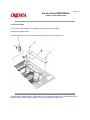
3.3.35 Separator Assembly
(1) Turn the AC power switch off. Unplug the AC power cord from the outlet.
(2) Pull out the paper cassette Assembly 1 from the printer.
(3) Release two locks and remove separator Assembly 2. (At this time, leaf spring 3 and coil
spring 4 are also removed. Be careful not to lose these springs.)
Copyright 1997, Okidata, Division of OKI America, Inc. All rights reserved. See the OKIDATA Business
Partner Exchange (BPX) for any updates to this material. (http://bpx.okidata.com)
Page: 61
Service Guide OKIPAGE16n
Chapter 3 Parts Replacement
3.3.36 Transfer roller
(1) Turn the AC power switch off. Unplug the AC power cord from the outlet.
(2) Open stacker cover 1.
(3) Lift the left side of the gear TR 2 and release the lock. Remove gear TR 2 and transfer roller
3. (At this time, two bearings (TR) 4 and two transfer roller springs 5 are also removed.)
(4) Remove diselectrification bar 6 and diselectrification film 7 from the chassis unit.
Copyright 1997, Okidata, Division of OKI America, Inc. All rights reserved. See the OKIDATA Business
Partner Exchange (BPX) for any updates to this material. (http://bpx.okidata.com)
Page: 62
Service Guide OKIPAGE16n
Chapter 4 Adjustment
4. ADJUSTMENT
This chapter explains the adjustment necessary when replacing a part. Adjustment is made by
changing a parameter value set in EEPROM on the controller PCB. A parameter is set with the key
operation on the operator panel. This printer has three kinds of maintenance modes. It is required to select
one of the maintenance modes necessary when replacing a part.
Copyright 1997, Okidata, Division of OKI America, Inc. All rights reserved. See the OKIDATA Business
Partner Exchange (BPX) for any updates to this material. (http://bpx.okidata.com)
Page: 63
Service Guide OKIPAGE16n
Chapter 4 Adjustment
4.1 Maintenance Modes And Functions
User maintenance mode
To enter the user maintenance mode, turn on the POWER switch while pressing the
key.
Function
There are seven functions as follows.
Menu reset
Hex dump
Drum counter reset
Operator panel menu disable
X adjust
Y adjust
Setting
System maintenance mode
Note: This mode is used only by service persons and it should not be released to the
end-users.
To enter the system maintenance mode, turn on the POWER switch while pressing the
RECOVER key.
Function
There are 8 functions as follows.
Page count display
Page count printing enable/disable
Rolling ASCII continuous printing
EEPROM reset
HSP ERROR recovery
MENU
HSP ERROR count display
HSP ERROR count reset
SIDM enable/disable
Engine maintenance mode
Note: This mode is used only by service persons and it should not be released to the end-users.
To enter the engine maintenance mode, turn on the POWER switch while pressing the
FORM FEED key and ENTER key.
Function
There are 15 functions as follows.
Head drive time setting
Setting of Head drive timing compensation while OST is on.
Compensated head type setting
Printing start position setting
Drum counter total display
Drum count display
Setting of standard paper feed length
Setting of front feeder paper feed length
Setting of second tray paper feed length
Selection of second tray feeder download table
Setting of envelope feeder paper feed length
Selection of envelope feeder download table
Fuser count indication
Fuser count reset
Engine reset
Copyright 1997, Okidata, Division of OKI America, Inc. All rights reserved. See the OKIDATA Business
Partner Exchange (BPX) for any updates to this material. (http://bpx.okidata.com)
Page: 64
Service Guide OKIPAGE16n
Chapter 4 Adjustment
4.1.1 User maintenance mode
To enter the user maintenance mode, turn the power supply ON while pressing the Menu key.
This mode uses the menu for function selection.
The user maintenance mode provides the following functions:
(1) Menu reset
All settings for Menu level-1 are reset to the factory default values.
The menus for all executable emulations including options are reset to the factory
default values.
The operation mode starts automatically upon completion of resetting.
(2) Hex dump
The data received from the host is dumped in hexadecimal notation to the printer.
Printing is activated automatically when the received data exceeds one page. If the
received data is less than one page, printing can be activated manually by pressing the
Form Feed key after selecting the OFF LINE mode by pressing the ON-LINE key.
(Automatic activation of printing even when the received data is less than one page by
selecting the Auto Eject function on the menu.)
Exit from this mode by turning the power OFF.
(3) Drum counter reset
This function resets the drum life data when the user replaces the image drum unit.
The operation mode starts automatically upon completion of resetting.
(4) Operator panel menu disable
This function is for enabling and disabling the operator panel menu functions (Menu
1, Menu 2, Tray Select, Copies and Paper Size).
(5) X ADJUST
This function is used to adjust the printing start position within the range of ±2 mm in
0.25 mm steps in the X direction.
(6) Y ADJUST
This function is used to adjust the printing start position within the range of ±2 mm in
0.25 mm steps in the Y direction.
(7) SETTING
-2 }
-1 }
0
+1 }
+2 }
This function is used to improve print quality.
Rough/thick paper, Low temperature/humidity and/or blotchy faded print appeared.
Normal media/environmental conditions.
Rough papers, high temperature/humidity and/or snowy print of high density pattern.
Copyright 1997, Okidata, Division of OKI America, Inc. All rights reserved. See the OKIDATA Business
Partner Exchange (BPX) for any updates to this material. (http://bpx.okidata.com)
Page: 65
Service Guide OKIPAGE16n
Chapter 4 Adjustment
User maintenance mode menu system
Copyright 1997, Okidata, Division of OKI America, Inc. All rights reserved. See the OKIDATA Business
Partner Exchange (BPX) for any updates to this material. (http://bpx.okidata.com)
Page: 66
Service Guide OKIPAGE16n
Chapter 4 Adjustment
4.1.2 System maintenance mode
The system maintenance mode is set when the power is turned ON while pressing the Recover key.
This mode adopts the menu for function selection.
The system maintenance mode is provided with the listed functions.
(1) Page count display
The total number of pages counted at the engine is displayed on the LCD.
(2) Page count printing enable/disable
This function selects whether to include (enable) or exclude (disable) the total number
of printed pages counted at the engine at the time of menu printing.
(3) Rolling ASCII continuous printing
The rolling ASCII pattern is printed continuously for various engine tests.
Press the ON-LINE key to cancel this mode.
(4) EEPROM reset
All EEPROM areas (including Menu level-2) are set to the factory default values.
The following items are excluded
Head drive time setting
Fine adjustment of printing start position
Standard tray paper feed amount setting
Transition to the operation mode occurs upon completion of resetting.
Press the Menu key to update each category.
The operation returns to the first category after updating the last category.
(5) HSP ERROR recovery
Select HSP ERROR recovery function either recover or stop.
(6) HSP ERROR count
Display total HSP ERROR count.
(7) HSP ERROR count reset
Reset the HSP ERROR counter.
(8) SIDM enable/disable
If it's selected disable, cannot select SIDM emulations by Menu.
Copyright 1997, Okidata, Division of OKI America, Inc. All rights reserved. See the OKIDATA Business
Partner Exchange (BPX) for any updates to this material. (http://bpx.okidata.com)
Page: 67
Service Guide OKIPAGE16n
Chapter 4 Adjustment
4.1.3 Engine maintenance mode
The engine maintenance mode is activated when the power is turned ON while pressing to
the Form Feed key and Enter key.
This mode adopts the menu for function selection.
The method for exit from this mode depends on the setting.
The engine maintenance mode is provided with the following functions:
(1) Head drive time setting
Sets the drive time of the LED head.
(2) Setting of Head drive timing compensation while OST is on.
This function sets head drive timing compensation level while OST is on at 600 DPI
mode.
(3) Compensated head type setting
This function sets type of the compensated head.
(4) Printing start position setting
Sets the printing start position.
(5) Drum count total display
Displays on the LCD the total number of drum revolutions in the unit counted at the
engine.
(6) Drum count display
Displays on the LCD the total number of EP drum revolutions counted at the engine.
(7) Setting of standard tray paper feed length
This function sets the paper feed length of standard tray paper.
(8) Setting of front feeder paper feed length
This function sets the paper feed length of the front feeder.
(9) Setting of High Capacity Second Paper Feeder paper feed length
This function sets the paper feed length of the High Capacity Second Paper Feeder.
(10) Selection of High Capacity Second Paper Feeder download table
This function selects the download table for the High Capacity Second Paper Feeder.
(11) Setting of Multi Feeder paper feed length
This function sets the paper feed length of the Multi Feeder.
(12) Selection of Multi Feeder download table
This function selects the download table for the Multi Feeder.
(13) Fuser count display
Displays on the LCD the total number of printed pages counted at the engine.
(14) Fuser count reset
When the fuser unit is replaced, the maintenance person uses this fuser count reset
function to reset the fuser lifetime.
After the fuser counter is reset, the engine enters into the operation mode automatically
(15) Engine reset
All EEPROM areas used by the engine are reset to the factory default values.
The following items are excluded:
Menu level-1
Menu level-2
Operator panel menu disable/enable
Page print disable/enable
Transition to the operation mode occurs upon completion of resetting.
Note: Do not change the default value of (2), (5), (8) ~ (13) they are the parameter for adjusting
in the factory.
Engine maintenance mode menu system
Copyright 1997, Okidata, Division of OKI America, Inc. All rights reserved. See the OKIDATA Business
Partner Exchange (BPX) for any updates to this material. (http://bpx.okidata.com)
Page: 68
Service Guide OKIPAGE16n
Chapter 4 Adjustment
4.1.4 EEPROM initialization
The corresponding area of the EEPROM is initialized for each event as shown Table 4-1.
Copyright 1997, Okidata, Division of OKI America, Inc. All rights reserved. See the OKIDATA Business
Partner Exchange (BPX) for any updates to this material. (http://bpx.okidata.com)
Page: 69
Service Guide OKIPAGE16n
Chapter 4 Adjustment
4.2 Adjustment When Replacing A Part
Adjustment becomes necessary when replacing one of the following parts.
Part Replaced
LED Head
Image Drum Cartridge
Fuser Unit
EEPROM
Adjustment
)
Set the LED head drive time. (Refer to Chapter 4.2.1
Reset the image drum counter. (Refer to User's manual)
)
Reset the fuser counter. (Refer to Chapter 4.2.2
)
Set the LED head drive time. (Refer to Chapter 4.2.1
Copyright 1997, Okidata, Division of OKI America, Inc. All rights reserved. See the OKIDATA Business
Partner Exchange (BPX) for any updates to this material. (http://bpx.okidata.com)
Page: 70
Service Guide OKIPAGE16n
Chapter 4 Adjustment
4.2.1 Setting of LED head drive time
Note: When the luminous intensity marking of the replaced LED head (new part) is the same
as that of the used LED head (old part), do not set the LED head drive time.
Luminous intensity marking label
(1) Normal Type LED HEAD
Setting of LED head drive time
Drive time of the LED head is to set parameter of drive time setting values corresponding to
the lumious intensity displays marked on the LED head to EEPROM.
a. Corresponding table of lumious energy display and drive time parameter
b. Setting
Example: Setting method the parameter to 14 (in case of privous parameter is 17).
Copyright 1997, Okidata, Division of OKI America, Inc. All rights reserved. See the OKIDATA Business
Partner Exchange (BPX) for any updates to this material. (http://bpx.okidata.com)
Page: 71
Service Guide OKIPAGE16n
Chapter 4 Adjustment
4.2.2 Resetting the fuser counter
Copyright 1997, Okidata, Division of OKI America, Inc. All rights reserved. See the OKIDATA Business
Partner Exchange (BPX) for any updates to this material. (http://bpx.okidata.com)
Page: 72
Service Guide OKIPAGE16n
Chapter 4 Adjustment
4.2.3 Destination setting
The desired destination can be set by turning the power on while depressing two keys corresponding to
the destination according to the following table.
Destination
ODA
OEL
OKI-INT-A
(Australia, etc.)
OKI-INT-L
(Singapore, etc.)
Keys to be depressed
MENU, >
MENU, <
MENU, PAPER SIZE
MENU, TRAY TYPE
Copyright 1997, Okidata, Division of OKI America, Inc. All rights reserved. See the OKIDATA Business
Partner Exchange (BPX) for any updates to this material. (http://bpx.okidata.com)
Page: 73
Service Guide OKIPAGE16n
Chapter 5 Periodical Maintenance
5.1 Periodic Part Replacement
As specified below, the parts shall be replaced periodically.
Part name
Condition for
replacement
- Toner cartridge
5,000
- Image drum cartridge 30,000
Cleaning
Remarks
- LED head.
- LED head.
Consumables
Consumables
Copyright 1997, Okidata, Division of OKI America, Inc. All rights reserved. See the OKIDATA Business
Partner Exchange (BPX) for any updates to this material. (http://bpx.okidata.com)
Page: 74
Service Guide OKIPAGE16n
Chapter 5 Periodical Maintenance
5.2 Cleaning
Remove any toner and dust. Clean inside and around the printer with a piece of cloth when
necessary. Use the handy cleaner (VACUUM) for cleaning the printers interior.
Note: Do not touch image drum, LED lens array, and LED head connector block.
Copyright 1997, Okidata, Division of OKI America, Inc. All rights reserved. See the OKIDATA Business
Partner Exchange (BPX) for any updates to this material. (http://bpx.okidata.com)
Page: 75
Service Guide OKIPAGE16n
Chapter 5 Periodical Maintenance
5.2.1 Cleaning of LED lens array
Clean the LED lens array or replace the toner cartridge when white lines or stripes (void, light
printing) are generated vertically down the page.
Note: The LED lens array must be cleaned with an LED head cleaner.
Copyright 1997, Okidata, Division of OKI America, Inc. All rights reserved. See the OKIDATA Business
Partner Exchange (BPX) for any updates to this material. (http://bpx.okidata.com)
Page: 76
Service Guide OKIPAGE16n
Chapter 6 Troubleshooting Procedures
6.1 Troubleshooting Tips
(1) Check the basic check points covered in the user's manual.
(2) Gather as much information on the problem from the customer as possible.
(3) Perform inspections in conditions close to those in which the problem had occurred.
Copyright 1997, Okidata, Division of OKI America, Inc. All rights reserved. See the OKIDATA Business
Partner Exchange (BPX) for any updates to this material. (http://bpx.okidata.com)
Page: 77
Service Guide OKIPAGE16n
Chapter 6 Troubleshooting Procedures
6.2 Points to Check before Correcting Image Problems
(1) Is the printer being run in proper ambient conditions?
(2) Have the supplies (toner) and the routine replacement part (image drum cartridge) been
replaced properly?
(3) Is the paper normal? See paper specifications section.
(4) Has the image drum cartridge been loaded properly?
Copyright 1997, Okidata, Division of OKI America, Inc. All rights reserved. See the OKIDATA Business
Partner Exchange (BPX) for any updates to this material. (http://bpx.okidata.com)
Page: 78
Service Guide OKIPAGE16n
Chapter 6 Troubleshooting Procedures
6.3 Tips for Correcting Image Problems
(1) Do not touch, or bring foreign matter into contact with the surface of the image drum.
(2) Do not expose the image drum to direct sunlight.
(3) Keep hands off the fuser unit as it is heated during operation.
(4) Do not expose the image drum to light for longer than 5 minutes at room temperature.
Copyright 1997, Okidata, Division of OKI America, Inc. All rights reserved. See the OKIDATA Business
Partner Exchange (BPX) for any updates to this material. (http://bpx.okidata.com)
Page: 79
Service Guide OKIPAGE16n
Chapter 6 Troubleshooting Procedures
6.4 Preparation for Troubleshooting
Operator Panel Display
Copyright 1997, Okidata, Division of OKI America, Inc. All rights reserved. See the OKIDATA Business
Partner Exchange (BPX) for any updates to this material. (http://bpx.okidata.com)