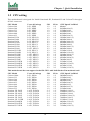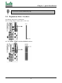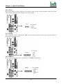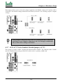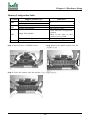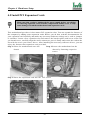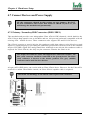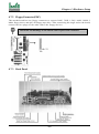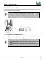
1
Contents
Chapter 1Quick Installation ..................... 3
1.1Layout ....................................................................................... 3
1.2CPU setting ............................................................................... 4
1.3Jumpers ..................................................................................... 5
1.4Expansion Slots / Sockets ........................................................ 8
1.5Connectors .............................................................................. 10
1.6Form Factor ............................................................................ 16
Chapter 2Overview.................................. 17
Chapter 3Features ................................... 20
3.1Motherboard Components Placement................................... 20
3.2Back Panel .............................................................................. 22
3.3Block Diagram ........................................................................ 23
3.4Specifications .......................................................................... 24
Chapter 4Hardware Setup ...................... 26
4.1 Before Installation ................................................................. 26
4.3 Install the Processor .............................................................. 31
4.4 Install Memory Modules ....................................................... 35
4.5 Install PCI Expansion Cards ................................................. 37
4.6 Usage of the AMR slot .......................................................... 38
4.7 Connect Devices and Power Supply ..................................... 39
WS133 Series Rev 1.1B
1
FB2A319201100
Chapter 1 Quick Installation
Chapter 5BIOS Setup ............................. 50
5.1 Introduction............................................................................ 50
5.2 Main Menu ............................................................................. 51
5.3 Standard CMOS Features .................................................... 52
5.4 Advanced BIOS Features ..................................................... 54
5.5 Advanced Chipset Features .................................................. 57
5.6 Integrated Peripherals .......................................................... 60
5.7 Power Management Setup .................................................... 65
5.8 PnP/ PCI Configurations ....................................................... 68
5.9 PC Health Status ................................................................... 69
5.10 IWILL Smart Setting .......................................................... 70
5.11 Load Fail-Safe Defaults ...................................................... 72
5.12 Load Optimized Defaults .................................................... 73
5.13 Set Supervisor / User Password Setting ............................ 73
5.14 Save & Exit Setup ............................................................... 73
5.15 Exit Without Saving ............................................................ 73
Chapter 6 Power Installer CD................ 74
6.1 Software Installation ............................................................. 74
6.2 How to use the Power installer CD ...................................... 74
6.3 Installing Operating Systems ................................................ 76
Appendix
Install the Suspend to IDE Hard Disk Utility ........................... 78
2
WS133 Series
Chapter 1 Quick Installation
Chapter 1
Quick Installation
Several easy installation steps will be described in this chapter to help the experienced users with
quick installation. If you are a beginner, or need to know more about this product, please refer to
Hardware Setup.
1.1 Layout
WS133 Series
3
Chapter 1 Quick Installation
1.2 CPU setting
This motherboard is designed for Intel® Pentium® III, Pentium® II and Celeron™ through a
SC242 connector.
CPU Model
Celeron 266
Celeron 300
Celeron 333
Celeron 366
Celeron 400
Celeron 433
Pentium II 350
Pentium II 400
Pentium II 450
Pentium III 450
Pentium III 500
Pentium III 550
Pentium III 600
Pentium III 533B
Pentium III 600B
Pentium III 550E
Pentium III 600E
Pentium III 650E
Pentium III 700E
Pentium III 533EB
Pentium III 600EB
Pentium III 667EB
Pentium III 733EB
Vcore & Package
2.0V, SEPP
2.0V, SEPP
2.0V, SEPP
2.0V, SEPP
2.0V, SEPP
2.0V, SEPP
2.0V, SECC(2)
2.0V, SECC(2)
2.0V, SECC(2)
2.0V, SECC2
2.0V, SECC2
2.0V, SECC2
2.05V, SECC2
2.0V, SECC2
2.0V, SECC2
1.65V, SECC2
1.65V, SECC2
1.65V, SECC2
1.65V, SECC2
1.65V, SECC2
1.65V, SECC2
1.65V, SECC2
1.65V, SECC2
JP3
1-2
1-2
1-2
1-2
1-2
1-2
2-3
2-3
2-3
2-3
2-3
2-3
2-3
2-3
2-3
2-3
2-3
2-3
2-3
2-3
2-3
2-3
2-3
JP3A
1-2
1-2
1-2
1-2
1-2
1-2
1-2
1-2
1-2
1-2
1-2
1-2
1-2
2-3
2-3
1-2
1-2
1-2
1-2
2-3
2-3
2-3
2-3
“CPU Speed” in BIOS
Manual
300Mhz(66x4.5)
333Mhz(66x5)
366Mhz(66x5.5)
400Mhz(66x6)
433Mhz(66x6.5)
350Mhz(100x3.5)
400Mhz(100x4)
450Mhz(100x4.5)
450Mhz(100x4.5)
500Mhz(100x5)
550Mhz(100x5.5)
600Mhz(100x6)
533Mhz(133x4)
600Mhz(133x4.5)
550Mhz(100x5.5)
600Mhz(100x6)
650Mhz(100x6.5)
700Mhz(100x7)
533Mhz(133x4)
600Mhz(133x4.5)
667Mhz(133x5)
733Mhz(133x5.5)
This motherboard also can support Socket370 CPUs with Iwill Slocket II transitional card.
CPU Model
Celeron 300A
Celeron 333
Celeron 366
Celeron 400
Celeron 433
Celeron 466
Celeron 500
Celeron 533
Pentium III 500E
Pentium III 550E
Pentium III 600E
Pentium III 650E
Pentium III 700E
Pentium III 533EB
Pentium III 600EB
Pentium III 667EB
Pentium III 733EB
Vcore & Package
2.0V, PPGA
2.0V, PPGA
2.0V, PPGA
2.0V, PPGA
2.0V, PPGA
2.0V, PPGA
2.0V, PPGA
2.0V, PPGA
1.60V, FCPGA
1.60V, FCPGA
1.65V, FCPGA
1.65V, FCPGA
1.65V, FCPGA
1.60V, FCPGA
1.65V, FCPGA
1.65V, FCPGA
1.65V, FCPGA
JP3
1-2
1-2
1-2
1-2
1-2
1-2
1-2
1-2
2-3
2-3
2-3
2-3
2-3
2-3
2-3
2-3
2-3
4
JP3A
1-2
1-2
1-2
1-2
1-2
1-2
1-2
1-2
1-2
1-2
1-2
1-2
1-2
2-3
2-3
2-3
2-3
“CPU Speed” in BIOS
300Mhz(66x4.5)
333Mhz(66x5)
366Mhz(66x5.5)
400Mhz(66x6)
433Mhz(66x6.5)
466Mhz(66x7)
500Mhz(66x7.5)
533Mhz(66x8)
500Mhz(100x5)
550Mhz(100x5.5)
600Mhz(100x6)
650Mhz(100x6.5)
700Mhz(100x7)
533Mhz(133x4)
600Mhz(133x4.5)
667Mhz(133x5)
733Mhz(133x5.5)
WS133 Series
Chapter 1 Quick Installation
1.3 Jumpers
JP1 (CMOS) Clear CMOS jumper
The jumper is for BIOS setting value.
JP3 & JP3A (FSB) CPU FSB select jumper
These jumpers allow the selection of the CPU’s based external frequency. The CPU “External Frequency” multiplied by the “Frequency Multiple” equals the CPU’s “Internal Frequency”. Currently,
most of the processors have the Frequency Multiple locked, so you only need to select the External
Frequency. This motherboard will detect the proper external frequency your CPU used, so you
can leave these jumpers on their defaults, and the based external frequency will be determined by
CPU automatically. In this case you need not go to BIOS to do setup.
If you want to have some further setting, the CPU speed is setup using “IWILL Smart Setting”.
This is found in the BIOS setup program by pressing <Del> during the boot up process.
WS133 Series
5
Chapter 1 Quick Installation
JP6 (PS2_SB) PS/2 power standby jumper
This jumper is used to select the power well of PS/2 ports. The feature “power on by keyboard
/ mouse” can be enabled or disabled by this jumper.
JP9 (Vcore+ ) Vcore booster jumper
This jumper is used to select the CPU core voltage.
JP10 (VIO) VIO select jumper
This jumper is used to select the VIO voltage.
6
WS133 Series
Chapter 1 Quick Installation
JP13 (AC 97) AC97 Codec Enabled / Disabled jumper
This jumper is used to enable / disable the onboard audio CODEC.
JP15 (LAN) LAN Enabled / Disabled jumper (WS133-N only)
This jumper is used to enable / disable the onboard LAN chip.
JP16 (FLASH) FLASH protect jumper
This jumper is used to select the Flash ROM protected mode.
WS133 Series
7
Chapter 1 Quick Installation
Do not leave JP16 without any cap.
1.4 Expansion Slots / Sockets
J1 (Slot1) Processor connector
Slot1 is Single Edge Contact (SEC) CPU slot.
J3—J5 (DM0—DM2) 168-Pin DIMM Sockets
8
WS133 Series
Chapter 1 Quick Installation
Install memory in any combination as follows:
Location
DM0
DM1
DM2
Support Module Type
Single-Side Module
Double-Side Module
Single-Side Module
Double-Side Module
Limitation
No
No
DM2 must be empty
1.DM1 must have a single-side
module
Single-Side Module
2.Must be the same or half
memory size of DM1
Double-Side Module
DM1 must be empty
Total System Memory (Max 512 MB)
J12—J17 (PCI 1—PCI 6) PCI expansion slots
The connectors are Bus Master PCI Expansion Slots.
J27 (AMR) AMR Slot
WS133 Series
9
Chapter 1 Quick Installation
1.5 Connectors
J28 (IDE0) Primary ATA/66 IDE channels
J29 (IDE1) Secondary ATA/66 IDE channels
J30 (FDC) Floppy connector
J32 (COM2)
This is an internal connector for COM2 port.
10
WS133 Series
Chapter 1 Quick Installation
J36 ATX keyboard connector (KB)
This connector allows you to use an internal keyboard connector instead of having to attach the
keyboard onto the ATX back-panel connectors.
J37 ATX power connector
J39 (FCPU) & J40 (FAUX) & J41 (FSYS)
There are three fan connectors on this motherboard. The J39 (FCPU) is designed to support CPU fan; the
J41 (FSYS) is for system fan used and you can connect any auxiliary fan to the J40 (FAUX).
WS133 Series
11
Chapter 1 Quick Installation
J40A (TAUX) & J41A (TSYS)
This motherboard has two temperature sensor headers. You can connect the temperature sensor to
these headers in order to monitor the temperature.These two connectors without orientation limit.
J43
This connector is composed of all the headers that may be connected to the front panel of the chassis.
J45 (IR)
This connector is designed for the SIR/FIR/CIR devices.
12
WS133 Series
Chapter 1 Quick Installation
J46 (WOL)
This is the Wake-on-LAN connector. In order to wake up the system through a plug-in network
card, the card must provide a high active wake signal.
J47 (WOM)
This connector can be connected to MR card or internal modem card to provide the ability of
power on by modem device.
J48 (SMBUS)
This connector provides the connectivity of SMBUS utilization.
WS133 Series
13
Chapter 1 Quick Installation
J52 (PTI,optional)
The flat panel and TV out functions can be supported through this connector.
This connector only supports the digital LCD panel. An analog LCD panel
comes with a 15 -pin VGA connector can be used on the external VG
connector.
Iwill PI and TI only use on the Iwill motherboard of WS133 version 1.1
and WA133 version 1.1.
J54 (CD_IN)
The audio output can be transfered from CD-ROM to the audio system through this connector directly.
J31
J33
J35
J38
J49
J55
External COM1 connector
External Parallel connector
External PS/2 mouse & keyboard connector
External Dual USB & RJ45 connector
External VGA connector
External Game / Line-in / Line-out / MIC connector
14
WS133 Series
Chapter 1 Quick Installation
WS133 Series
15
Chapter 1 Quick Installation
1.6 Form Factor
16
WS133 Series
Chapter 2 Overview
Chapter 2
Overview
Thank you for purchasing the IWILL WS133 motherboard. This operation manual will instruct you how to configure and install the system properly. It contains an overview about the
engineering design and features of this product. Also, this manual provides useful information
for later upgrades or configuration changes. Keep this for your future reference.
About This Manual
This manual will introduce to the user how this product is installed. All useful information will be
described in later chapters. Keep this manual for future upgrades or system configuration changes.
Chapter 1 Quick Installation
Chapter 2 Overview
Chapter 3 Features
Chapter 4 Hardware Setup
Chapter 5 BIOS Setup
Chapter 6 Power Installer CD
The quick reference for experienced user
An overview of this motherboard
Information and specifications
Information for setting up the motherboard
Information for setting up the system BIOS
Information for the Power Installer CD
Item Checklist
You should find the following components when opening the box:
[Ô]
Iwill motherboard
[Ô]
This operation manual
[Ô]
One 40-pin/80-thread ATA/66 IDE cable with three heads
[Ô]
One 34-pin Floppy cable with four heads
[Ô]
One 10-pin to 9-pin COM port transitional cable (including a bracket)
[Ô]
One Iwill Power Installer CD
[Ô]
Bag of spare jumper caps
[Ô]
One Customer ATX IO Shield
Optional
[ ]
Thermal Sensor for HDD
[ ]
Thermal Sensor for System
[ ]
Iwill Slocket II CPU transitional card - Socket370-to-Slot1
[ ]
Iwill SIDE-Pro66 PCI ATA/66 IDE controller
[ ]
Iwill SIDE-2930C PCI Fast SCSI controller
[ ]
Iwill SIDE-2930CB PCI Fast SCSI controller
[ ]
Iwill SIDE-2936UW PCI Ultra Wide SCSI controller
[ ]
Iwill SIDE-2935LVD PCI Ultra2 SCSI controller
[ ]
Iwill SIDE-DU280 PCI Dual channel Ultra2 SCSI controller
[ ]
MR card
WS133 Series
17
Chapter 2 Overview
Introduction
The WS133 series motherboard is the most flexible platform in today’s market based on the
newest Intel® i810E chipset. A major advancement in chipset technology, the Intel® i810E
integrates 3D graphics engine directly into the chipset to deliver a high-quality 3D experience.
Combining Intel® 3D graphics with the onboard audio CODEC, AMR slot and the optional
LAN chip results in a comprehensive, compatible platform that offers system integrators a
comprehensive and cost-effective solution.
This motherboard supports both the current (Deschutes / Katmai) and the next generation of processors (Coppermine) without any headache. With the optional Slocket II transitional card, it even can
support the processors that packed as a PPGA or FCPGA type. In other words, no matter what kind of
processors you have, the WS133 motherboard always provides you an adequate solution.
There are three DIMM sockets on the motherboard, which provide you the most flexibility of DRAM
usage. The original investment can be guaranteed by six bus-master PCI slots design. The PC99
compliant colorful connectors and the easy jumper setting provide the user more convenience. Besides that, the robust feature, well-prepared documents and the powerful software CD support make
this motherboard the best choice of the value segment.
Copyright
This manual contains information protected by copyright law. All rights are reserved. No part of this
document may be used or reproduced in any form or by any means, or stored in a database or retrieval system without prior written permission from Iwill Corporation.
Trademark
Intel® / Pentium® / Celeron™ are trademarks of Intel Corporation.
Iwill and Iwill logo are trademarks of Iwill Corp.
All other product names are trademarks and registered trademarks of their respective owners.
Warning
Most of the features of this product have passed strict verification tests, and are subject to change at
any time without prior notice. If any malfunction occurs due to the future technical changes made by
the respective component manufacturers, Iwill assumes no responsibility or liability for it.
Notice
Information furnished in this manual is believed to be accurate and reliable. However, Iwill
Corporation assumes no responsibility for its use, nor for any infringements of patents or other
rights of third parties which may result from its use. Iwill Corporation reserves the right to
change product specifications at any time without notice. Applications described in this document
for any of these products are for illustrative purposes only. Iwill Corporation makes no
representation nor warranty that such applications are suitable for the specified use without
further testing or modification. Iwill Corporation assumes no responsibility for any errors that
may appear in this document.
18
WS133 Series
Chapter 2 Overview
YEAR 2000 issue
All motherboard currently shipped from IWILL contain BIOS capable of handling
the year 2000 data correctly.
The IBM compatible PC utilizes a Motorola MC146818 compatible Real Time Clock (RTC)
chip to maintain the date and time. Unfortunately, the “century” is not manipulated by the
RTC. It uses 8-bits of information to report the year, and can only hold the last two digits of
a year in packed BCD format. For example, 1997 is reported solely as 97. Since the RTC also
contains non-volatile memory, IBM has specified a location in the memory to hold “century”
information. By combining the century data with the year data, software can obtain a full 4digit year. When the Year 2000 arrives, the RTC reports the year as ‘00’ and the “century” in
RTC memory will contain ’19.’ Combining the full 4-digit year yields 1900, not 2000. Any
application which compare dates, or uses relative dates to perform functions will see incorrect
dates.
All motherboards contain BIOS, which is one of the key ingredients to check for systems
designed to handle the year 2000. All motherboards currently shipped from IWILL
contain BIOS capable of handling the year 2000 date correctly.
Be aware that the BIOS capability alone does not ensure that the system will handle the transition
correctly. Other system components such as the operating system and application software also need
to be able to handle the year 2000 date, and recognize the date format from other sources.
EC Declaration of Conformity
We
IWILL Corporation
No. 10, Wu Chuan 3rd Rd.,
Hsin Chuang City, Taipei,
Taiwan, R.O.C.
Declare under sole responsibility that the
WS133 motherboard
Meets the intent of Directive 89/336/ECC for Electromagnetic Compatibility. Compliance was demonstrated to the following specifications as listed in the official Journal of the European Communities:
EN 50081-1
Emissions:
EN 55022
Radiated, Class B
EN 55022
Conducted, Class B
EN 60555-2
Power Harmonics
EN 50082-1
Immunity:
IEC
801-2 Electrostatic Discharge
IEC
801-3 RF Radiate
IEC
801-4 Fast Transient
WS133 Series
19
Chapter 3 Features
Chapter 3
Features
This Iwill WS133/WS133-N motherboard are well designed for the user. Who wants the most
stable plat form, best performance/price ratio and convenience.
3.1 Motherboard Components Placement
20
WS133 Series
Chapter 3 Features
The following are part descriptions for the motherboard parts shown on the opper page.
1: ATX Power Connector
2: SC242 Slot1 Connector
3: Display Cache Memory
4: Intel 810E GMCH
5: Three DIMM Sockets
6: Floppy Connector
7: Primary and Secondary IDE Connectors
8: Intel ICH Chipset
9: Intel FWH Chipset (Programmable BIOS)
10:Multi-I/O Chip
11:COM2 Header
12:LAN Chip 10/100M BaseT (WS133-N only)
13:32bit/33MHz Bus Master PCI Slot
14:AC'97 V2.1 Audio CODEC
15:PTI header (Optional)
16:AMR Slot
17:Joystick, Midi Line Out ,Line in, Microphone In Connector
18:VGA Monitor Connector
19:Parallel Connector
20:COM1 Connector
21:LAN and USB Connector (LAN Optional)
22:PS/2 Mouse, PS/2 Keyboard Connector.
WS133 Series
21
Chapter 3 Features
3.2 Back Panel
22
WS133 Series
Chapter 3 Features
3.3 Block Diagram
WS133 Series
23
Chapter 3 Features
3.4 Specifications
Processor
Supports one Slot1 connector with pre-installed URM (Universal Retention Mechanism)
Supports Intel® Celeron™ (Katmai, SEPP) CPU from 266 MHz to 433 MHz
Supports Intel® Pentium® II (Klamath / Deschutes, SECC/SECC2) CPU from 233 MHz to 450 MHz
Supports Intel® Pentium® III (Katmai, SECC2) CPU from 450 MHz to 600 MHz
Supports Intel® Pentium® III (CuMine-256, SECC2) CPU from 533 MHz to 733 MHz
Supports both H/W and S/W setting methods on CPU frequency selection
Supports CPU voltage auto detection
Supports adjustable CPU core voltage
ChipSet
Intel® i810E AGPset
Support 66/100/133 MHz CPU external frequency
Integrated 2X AGP controller supports up to 1600x1200x8bit color at 85 Hz refresh
Supports Hardware Motion Compensation for S/W MPEG Decode
Supports Software DVD at 30 fps
Supports 4MB Dynamic Display Memory
Supports 85MHz Flat Panel Monitor interface (optional)
Supports Digital Video Output for use with an external NTSC/PAL TV encoder (optional)
Main Memory
Supports three DIMM sockets
Supports 3.3V unbuffered PC100 SDRAM modules
Supports Single-sided and Double-sided DIMM modules
Supports 16M/32M/64M/128M/256M SDRAM modules
Supports up to 512MB memory when using 128M technology
Supports up to 256MB memory when using 64M/16M technology
Bus Master IDE
Supports dual channel IDE interface for up to four IDE devices
Supports Ultra DMA Bus Master with 66 MB/s burst data transfer rate
Supports PIO mode 0/1/2/3/4 and Multi-word mode 0/1/2/3/4
Supports HDD/Tape drive/CD-ROM/CD-R/CD-RW/LS120/ZIP drive
Multi-IO
Provides one floppy port to support 1.2M/1.4M/2.8M/3 Mode FDD and QIC-80 tape drive
Supports two high-speed 16550A serial ports
Supports one SPP/ECP/EPP parallel port
Supports one PS2 mouse port
Supports one PS2 keyboard port
Provides one Game/MIDI port to support two joysticks
Supports FIR and CIR infrared communication
Supports PS2 mouse and PS2 keyboard auto swapping
24
WS133 Series
Chapter 3 Features
USB
Supports two UHCI Universal Serial Bus ports
Supports USB keyboard/mouse/joystick/telephone/modem devices
Expansion Slots
Supports six Bus Master PCI slots
Supports one AMR slot for AR/MR/AMR cards
LAN on board (WS133-N only)
Build-in Realtek RTL8139B Ethernet LAN controller (10Base-T/100Base-TX)
Supports IEEE 802.3u Auto-Negotiation
Supports Full-Duplex Flow Control (IEEE 802.3x)
Supports Wake-Up on Magic packet, LinkChg and Microsoft wake-up frame (PME#)
Sound on board
Build-in AC‘97 Sound CODEC
Management
Supports ACPI 1.0 and APM 1.2 specification
Supports Suspend to Ram (STR)
Supports extra SMBUS connector
Supports Hardware Monitoring for the voltage, temperature and fan control
Supports Chassis Intrusion feature
Supports Power on by LAN/Ext. Modem/Int. Modem/PS2 Keyboard/PS2 Mouse/RTC Alarm
Supports ACPI Blinking LED
Supports “AC-Loss Recovery” feature
Supports Manually Assign PCI IRQ
Supports Auto-reboot function when system hang
Supports Remote Power-up using Wake-on-LAN technology
Fully Year2000 Compliance
BIOS
Adopt Award BIOS
Supports On-board upgrade ability
Supports BIOS ROM Flash protection
Others
ATX Form Factor 12“ x 7.5”
WS133 Series
25
Chapter 4 Hardware Setup
Chapter 4
Hardware Setup
4.1 Before Installation
For installation, you may need some or all of the following tools:
Medium size flat blade screwdriver
Medium size Phillips head screwdriver
A 3/16 inch nut driver or wrench
Users must follow these guidelines to ensure the motherboard is protected
during installation.
a. Make sure your computer is powered-off whenever working with inside
components.
b. The motherboard, like all other electronic equipment, is sensitive to
static. Please take the proper precautions when handling it. If possible,
ground yourself by touching a metal table or desk. keep the board in its
conductive wrapping until it is configured and ready to be installed in
your system.
c. Keep all magnets away from both your hard and floppy disk drives,
especially magnetic screwdrivers. Keep both floppy and hard disks
apart if disassembled.
d. Keep water and liquids away from your computer and its components.
4.2 Jumper setting
4.2.1 JP1 Clear CMOS jumper (CMOS)
To reset the CMOS data, you should turn off the computer first, take the JP1 jumper cap off pins
1-2, place onto pins 2-3, and then place back onto pins 1-2 again. Then, turn on your computer,
press <Del> key during boot up and enter the BIOS setup program to re-set your preferences.
26
WS133 Series
Chapter 4 Hardware Setup
4.2.2 JP3 & JP3A CPU FSB select jumper (FSB)
These jumpers allow the selection of the CPU’s based external frequency. The CPU “External
Frequency” multiplied by the “Frequency Multiple” equals the CPU’s “Internal Frequency”.
Currently, most of the processors have the Frequency Multiple locked, so you only need to
select the External Frequency. This motherboard will detect the proper external frequency your
CPU used, so you can leave these jumpers on their defaults, and the based external frequency will
be determined by CPU automatically. In this case you need not go to BIOS to do setup.
The CPU speed is setup using “IWILL Smart Setting”. This is found in the BIOS setup program
by pressing <Del> during the boot up process.
After you setting up these jumpers to assign the “Based External
Frequency” you should enter BIOS setup program, select the proper CPU
speed within “Iwill Smart Setting”page. The BIOS will display the proper
options depends on these jumpers setting. For example, if you choose
66Mhz by setting both JP3 and JP3A to 1-2, then the BIOS will prompt
you 66Mhz, 75Mhz and 83Mhz for selecting.
The table shows the proper setting for most of the processors in the market.
The WS133 is designed for Intel® Pentium® III, Pentium® II and Celeron™ through
a SC242 connector.
CPU Model
Vcore & Package JP3
JP3A “CPU Speed” in BIOS
Celeron 266
2.0V, SEPP
1-2
1-2
Manual
Celeron 300
2.0V, SEPP
1-2
1-2
300Mhz(66x4.5)
Celeron 333
2.0V, SEPP
1-2
1-2
333Mhz(66x5)
Celeron 366
2.0V, SEPP
1-2
1-2
366Mhz(66x5.5)
Celeron 400
2.0V, SEPP
1-2
1-2
400Mhz(66x6)
Celeron 433
2.0V, SEPP
1-2
1-2
433Mhz(66x6.5)
Pentium II 350
2.0V, SECC(2)
2-3
1-2
350Mhz(100x3.5)
Pentium II 400
2.0V, SECC(2)
2-3
1-2
400Mhz(100x4)
Pentium II 450
2.0V, SECC(2)
2-3
1-2
450Mhz(100x4.5)
WS133 Series
27
Chapter 4 Hardware Setup
Pentium III 450
2.0V, SECC2
2-3
1-2
450Mhz(100x4.5)
Pentium III 500
2.0V, SECC2
2-3
1-2
500Mhz(100x5)
Pentium III 550
2.0V, SECC2
2-3
1-2
550Mhz(100x5.5)
Pentium III 600
2.05V, SECC2
2-3
1-2
600Mhz(100x6)
Pentium III 533B
2.0V, SECC2
2-3
2-3
533Mhz(133x4)
Pentium III 600B
2.0V, SECC2
2-3
2-3
600Mhz(133x4.5)
Pentium III 550E
1.65V, SECC2
2-3
1-2
550Mhz(100x5.5)
Pentium III 600E
1.65V, SECC2
2-3
1-2
600Mhz(100x6)
Pentium III 650E
1.65V, SECC2
2-3
1-2
650Mhz(100x6.5)
Pentium III 700E
1.65V, SECC2
2-3
1-2
700Mhz(100x7)
Pentium III 533EB 1.65V, SECC2
2-3
2-3
533Mhz(133x4)
Pentium III 600EB 1.65V, SECC2
2-3
2-3
600Mhz(133x4.5)
Pentium III 667EB 1.65V, SECC2
2-3
2-3
667Mhz(133x5)
Pentium III 733EB 1.65V, SECC2
2-3
2-3
733Mhz(133x5.5)
This motherboard also can support Socket370 CPUs with Iwill Slocket II transitional
card.
CPU Model
Vcore & Package JP3
JP3A “CPU Speed” in BIOS
Celeron 300A
2.0V, PPGA
1-2
1-2
300Mhz(66x4.5)
Celeron 333
2.0V, PPGA
1-2
1-2
333Mhz(66x5)
Celeron 366
2.0V, PPGA
1-2
1-2
366Mhz(66x5.5)
Celeron 400
2.0V, PPGA
1-2
1-2
400Mhz(66x6)
Celeron 433
2.0V, PPGA
1-2
1-2
433Mhz(66x6.5)
Celeron 466
2.0V, PPGA
1-2
1-2
466Mhz(66x7)
Celeron 500
2.0V, PPGA
1-2
1-2
500Mhz(66x7.5)
Celeron 533
2.0V, PPGA
1-2
1-2
533Mhz(66x8)
Pentium III 500E
1.60V, FCPGA
2-3
1-2
500Mhz(100x5)
Pentium III 550E
1.60V, FCPGA
2-3
1-2
550Mhz(100x5.5)
Pentium III 600E
1.65V, FCPGA
2-3
1-2
600Mhz(100x6)
Pentium III 650E
1.65V, FCPGA
2-3
1-2
650Mhz(100x6.5)
Pentium III 700E
1.65V, FCPGA
2-3
1-2
700Mhz(100x7)
Pentium III 533EB 1.60V, FCPGA
2-3
2-3
533Mhz(133x4)
Pentium III 600EB 1.65V, FCPGA
2-3
2-3
600Mhz(133x4.5)
Pentium III 667EB 1.65V, FCPGA
2-3
2-3
667Mhz(133x5)
Pentium III 733EB 1.65V, FCPGA
2-3
2-3
733Mhz(133x5.5)
28
WS133 Series
Chapter 4 Hardware Setup
4.2.3 JP5 PCI compatibility jumper (JP5)
This jumper is for the internal use.
4.2.4 JP6 PS/2 power standby jumper (PS2_SB)
The computer can be powered on through PS/2 keyboard or PS/2 mouse. In order to support this
feature, the standby power must be provided to PS/2 ports.
4.2.5 JP9 Vcore booster jumper (Vcore+)
This jumper allows you to select the voltage supplied to the CPU. The default voltage should be
used unless processor over-clocking requires a higher voltage.
4.2.6 JP10 VIO select jumper (Vio)
WS133 Series
29
Chapter 4 Hardware Setup
This jumper allows you to select the voltage supplied to the DRAM, chipset, PCI and the CPU’s
I/O buffer. The default voltage should be used unless processor over-clocking requires a higher
voltage.
Using a higher voltage may help when over-clocking but may result in the
shortening of your computer component’s life. It is strongly recommended
that you leave these setting on its default.
4.2.7 JP13 AC’97 Codec Enabled / Disabled jumper (AC’97)
This jumper is used to enable / disable the onboard audio CODEC. The onboard audio CODEC
must be disabled when using an ISA/PCI audio card or a primary AMR card.
30
WS133 Series
Chapter 4 Hardware Setup
4.2.8 JP15 LAN Enabled / Disabled jumper (LAN) (WS133-N only)
This jumper is used to enable / disable the onboard LAN chip.
4.2.9 JP16 Flash protect jumper (FLASH)
This jumper is used to select the Flash ROM protected mode.
Do not leave JP16 without any cap.
4.3 Install the Processor
The WS133 motherboard provides one Single Edge Contact (SEC) slot to support Pentium ® III,
Pentium® II and Celeron™ processors.
WS133 Series
31
Chapter 4 Hardware Setup
All of the processors have two categories: OEM version and Boxed
version. The OEM version processor has no heat sink, fan and heat sink
support, while the Boxed version processor has all of them. Without a fan,
the processor could overheat and damage both the processor and the
motherboard. If this is the case, purchase a fan before you turn on your
computer.
This motherboard is shipped with a pre-installed Universal Retention Mechanism (URM), so
you can go through to install the processor directly.
Universal Retention Machanism
Step 1:
Lift each of the two retention mechanism brackets so that they stand fully upright. You should
hear a soft “click” sound once each bracket is in the correct upright position.
Step 2:
Insert the CPU horizontally into the retention mechanism, sliding both edges in simultaneously
and as “evenly” as possible. Then, press down gently yet firmly so that the CPU is fully inserted
correctly into the socket.
32
WS133 Series
Chapter 4 Hardware Setup
Step 3: Pull the clip beside retention mechanism upward to lock the CPU.
UNLOCK
LOCK
Do not forget to set the correct CPU External Frequency and Multiple
(Multiple setting is available only on unlocked processors) for your
processor or else boot up may not be possible.
Step 4: Finally, attach the fan cable to the CPU fan header FCPU.
WS133 Series
33
Chapter 4 Hardware Setup
Slocket II (Slocket 370-Slot1 Convertor)
Step 1: Lift each of the two retention mechanism brackets so that they stand fully upright. You
should hear a soft “click” sound once each bracket is in the correct upright position.
Step 2: Insert the CPU horizontally into the retention mechanism, sliding both edges in
simultaneously and as “evenly” as possible. Then, press down gently yet firmly so that the
CPU is fully inserted correctly into the socket.
34
WS133 Series
Chapter 4 Hardware Setup
Do not forget to set the correct CPU External Frequency and Multiple
(Multiple setting is available only on unlocked processors) for your
processor or else boot up may not be possible.
Step 3: Finally, attach the fan cable to the CPU fan header FCPU.
4.4 Install Memory Modules
The motherboard has three Dual Inline Memory Module (DIMM) sockets and supports the
maximum memory size up to 512MB. These DIMM sockets only support 3.3V unbuffered
SDRAM modules of 16M, 32M, 64M, 128M and 256M. The motherboard also support SPD
(Serial Presence Detect) architecture to provide the best choice for performance vs. stability.
1. The chipset does not support ECC. However, the ECC memory modules
may still be used, but the ECC function will not be available.
2. No hardware or BIOS setup is required after adding or removing
memory modules.
WS133 Series
35
Chapter 4 Hardware Setup
Memory Configuration Table
Location
DM0
DM1
DM2
Support Module Type
Single-Side Module
Double-Side Module
Single-Side Module
Double-Side Module
Limitation
No
No
DM2 must be empty
1.DM1 must have a single-side
module
Single-Side Module
2.Must be the same or half
memory size of DM1
Double-Side Module
DM1 must be empty
Total System Memory (Max 512 MB)
Step 1:Open latches of DIMM socket
Step 2:Insert the RAM module into the
DIMM Secket
Step 3: Press the latches into the notches of the RAM module
36
WS133 Series
Chapter 4 Hardware Setup
4.5 Install PCI Expansion Cards
Make sure that you have unplugged the power supply before you adding
or removing expansion cards or other component6. Failure to do so may
cause damage to both the motherboard and expansion cards.
This motherboard provides six bus master PCI expansion slots. You can expand the features of
the computer by adding some expansion cards. Before you do that, read the documentation for
your expansion card carefully and make any necessary hardware settings on it, such as jumpers
or switches. Locate a free expansion slot and remove the bracket plate with screw on the slot
you intend to use, carefully align the card’s connectors, press it firmly and secure the card on the
slot with the screw you remove above. After installing the necessary software drivers, you can
enjoy the features that expansion card provided.
Step 1:Place the motherboard onto the
Step 2:Secure the motherboard on the
chassis
chassis by fastening respective
screws
Step 3:Insert the expansion card into the PCI socket
WS133 Series
37
Chapter 4 Hardware Setup
Step 4:Secure the expansion card on the chassis by fastening the screw.
In the PCI bus design, the BIOS automatically assigns an IRQ to a PCI
slot that has a card in it. To check the IRQ map of your system in
Windows 98, the Control Panel icon in My Computer contains a System
icon, which gives you a Device Manager tab. Double click on a specific
hardware device gives you the Resource tab, which shows the IRQ and
address. Make sure that no two devices use the same IRQ or your
computer will experience problems. If your expansion card must be
performed with a specific IRQ, you can enter BIOS setup program to
assign the specific IRQ in PnP/PCI Configuration page.
4.6 Usage of the AMR slot
This motherboard provides a Audio Modem Riser (AMR) slot to support a specially designed audio
and/or modem card called an AMR card. Main audio and/or modem processing is done by system
processor to provide an upgradeable audio and/or modem solution at an incredibly low cost.
There are two type of AMR card, one defined as primary and another defined as secondary. This
motherboard uses the primary channel so that a secondary AMR card can coexist without the
need to disable the onboard audio CODEC. The onboard audio CODEC must be disabled when
using a primary AMR card.
38
WS133 Series
Chapter 4 Hardware Setup
4.7 Connect Devices and Power Supply
All the connectors showed in this section are not jumpers, DO NOT
PLACE JUMPER CAPS OVER THE PINS OF THEM. If you do so, you
will damage the motherboard permanently.
4.7.1 Primary / Secondary IDE Connectors (IDE0 / IDE1)
This motherboard provides two independent Ultra ATA/66 IDE channels, which doubles the
ATA/33 burst data transfer rate to 66 MB/s and are 100 percent backward compatible with all
existing ATA / ATAPI devices. These connectors also support ZIP and LS-120 devices.
The ATA/66 requires a special 40-pin, 80-conductor cable that reduces noise bleed-over and
improves signal integrity by providing 40 additional ground lines between each of the standard
40-pin ATA (IDE) signal lines and ground lines. Although a new 40-pin, 80-conductor cable is
required for Ultra ATA/66, the chip set pin connector remains the same at 40.
The 40-pin, 80-conductor cables will support the Cable Detect feature. The
blue (end) connector should be connected to the system board. The black
(end) connector is known as the master position. The gray (middle)
connector can be used for slave devices.
A legacy ATA (IDE) drive can coexist with an Ultra ATA/66 drive. However, for the Ultra ATA/
66 device to attain Ultra DMA 4 mode, an Ultra ATA/66 capable cable is required.
Orient the red markings on the ribbon cable to pin1 of the connector
WS133 Series
39
Chapter 4 Hardware Setup
4.7.2 Floppy Connector (FDC)
This motherboard has one floppy connector to support 360K, 720K, 1.2M, 1.44M, 2.88M, 3
Mode floppy drives and QIC-80 floppy tape drive. After connecting the single end to the board,
connect the two plugs on the other end to the floppy devices.
Orient the red markings on the ribbon cable to pin1 of the connector
4.7.3 Back Panel
40
WS133 Series
Chapter 4 Hardware Setup
4.7.3.1 PS/2 Mouse Connector (Green color)
This connector can be used to support a PS/2 mouse.
4.7.3.2 PS/2 Keyboard Connector (Purple color)
This connector can be used to support a PS/2 keyboard.
The PS/2 mouse and PS/2 keyboard can be auto-detected by this
motherboard. That means if you plug the PS/2 keyboard into the mouse
connector, it still can work without any trouble and vice versa. It i
recommended that you turn off the computer before connecting or
disconnecting keyboard and/or mouse.
4.7.3.3 Universal Serial Bus Connectors
This motherboard has two USB ports, any USB-compatible peripherals and/or hub can
be connected into either USB port.
4.7.3.4 Serial port COM1 Connector (Teal color)
One serial port is ready for a modem or other serial devices. A second serial port is
available using a serial port bracket connected from the motherboard to an expansion
slot opening.
4.7.3.5 Parallel port Connector (Burgundy color)
This connector is used for printers, or other parallel devices.
4.7.3.6 VGA Connector (Blue color)
This connector is for output to a VGA compatible device.
4.7.3.7 Joystick/Midi and Audio Port Connector (Gold color)
You may connect joysticks or game pads to this connector for playing games, or
connect MIDI devices for playing / editing professional audio. Line Out (Lime color)
can be connected to headphones or powered speakers. Line In (Light Blue color) allows
audio sources to be recorded by your computer or played through the Line Out connector.
Mic (Pink color) allows microphones to be connected for inputting voice.
4.7.3.8 Ethernet RJ45 Connector (for WS133-N only)
The RJ45 connector is optional at the time of purchase and is located on top of the USB
connectors. The connector allow the motherboard to connect to a Local Area Network
(LAN) through a network hub.
WS133 Series
41
Chapter 4 Hardware Setup
4.7.4 Serial Port COM2 Connector (COM2)
The optional serial port bracket can be used to add an additional serial port for serial
devices.
4.7.5 CPU, Auxiliary and System FAN Connectors (FCPU, FAUX and FSYS)
There are three fan connectors on this motherboard. The J39 (FCPU) is designed to support
CPU fan; the J41 (FSYS) is for system fan used and you can connect any auxiliary fan to the J40
(FAUX). Depending on the fan manufacturer, the wiring and plug may be different. In most of
the case, the red wire is positive, while the black is ground. Connect the fan’s plug to the board
taking into consideration the polarity of the connector.
The “Sense” signal is to be used only by a specially designed fan with rotation signal. You may
use the hardware monitoring utility to monitor the Rotations per Minute (RPM) of the fan.
42
WS133 Series
Chapter 4 Hardware Setup
1. The CPU will overheat if there is no airflow across the CPU heatsink.
2. Damage may occur to the CPU fan and/or motherboard if these pins
are incorrectly used.
4.7.6 Auxiliary and System Temperature Sensor Connectors (TAUX and TSYS)
This motherboard has two temperature sensor headers. You can connect the temperature
sensors to these headers in order to monitor the temperature.These two connectors without
orientation limit.
The CPU temperature can be monitored by a CPU inside thermal diode. If
your CPU does not have this feature, purchase one temperature sensor
and connect it to the Auxiliary Temperature Sensor Connector.
WS133 Series
43
Chapter 4 Hardware Setup
4.7.7 Front Panel Connector (J43)
This connector is composed of all the headers that may be connected to the front panel of the
chassis.
Power/Soft-Off Connector (PWR_ON)
The system power is controlled by a momentary button connected to this connector. Pressing
the button once will switch the system between ON and OFF. Pushing the button for more than
4 seconds will turn the system off.
ACPI LED Connector (ACPI)
This 2-pins connector is for a ACPI power status indicator. The LED status will depend on the
connector.
Chassis Intrusion Connector (CASE)
This connector is for a chassis designed for chassis intrusion detection. After-market toggle
switches may also be installed to the chassis panel or on any removable components. Two wires
should be available from the chassis to connect to this connector. When any chassis component
is removed, the contact should open and the motherboard will record a chassis intrusion event.
If this feature is not used, a jumper cap must be placed over the 2 pins of the connector.
IDE LED Connector (ALED)
This 2-pin connector connects to the case-mounted IDE LED, which lights when the IDE
devices connected to the primary / secondary IDE connectors are working.
Reset Connector (RST)
This 2-pin connector connects to the case-mounted reset button for rebooting your computer
without having to turn off the power supply.
System Power LED Connector (PLED)
This 3-pin connector connects to the case-mounted system power LED, which lights when the
system is powered on.
Keyboard Lock Connector (KL)
This 2-pin connector connects to the case-mounted key switch to allow keyboard locking.
Speaker Connector (SPKR)
This 4-pin connector connects to the case-mounted speaker.
44
WS133 Series
Chapter 4 Hardware Setup
4.7.8 Infrared Connector (IR)
This connector supports an optional wireless transmitting and receiving infrared device when
using the appropriate application software.
a. When using a SIR/FIR devices, you need to enter the BIOS setup
program and configure the ART Mode Select?field as “IrDA”.
b. When using a CIR device, the jumper cap of JP6 should be placed over
1-2 in order to use Consumer Infrared power up.
4.7.9 Wake-On-LAN Connector (WOL)
This connector connects to a plug-in network card, which supports the WOL technology to
powers up the system when a wakeup packet or signal is received through the LAN card.
a. You may need to enable the “Wake Up by Ring/LAN” feature in the
BIOS setup program.
b. Your system must have a ATX power supply with at least 720mA 5VSB
power.
c. This motherboard only supports the LAN card with a high-active wake
signal.
WS133 Series
45
Chapter 4 Hardware Setup
4.7.10 Wake-On-Modem Connector (WOM)
This connector connects to internal modem cards (PCI or AMR) with a Wake-On-Modem
output to powers up the system when a ringup packet or signal is received through the modem
card.
a. For the external Modems, the Wake-On-Modem is detected through the
COM port.
b. You need to enable the “Wake Up by Ring/LAN” feature in the BIO
setup program.
c. Your system must have a ATX power supply with at least 720mA 5VSB
power.
46
WS133 Series
Chapter 4 Hardware Setup
4.7.11 SMBUS connector J48 (SMBUS)
This connector provides the connectivity of SMBUS utilization.
4.7.12 ATX keyboard connector J36 (KB)
This connector allows you to use an internal keyboard connector instead of having to attach the
keyboard onto the ATX back-panel connectors.
4.7.13 Flat Panel &TV-Out slot J52 (PTI, optional)
The flat panel and TV out functions can be supported through this connector.
This connector only supports the digital LCD panel. An analog LCD panel
comes with a 15 -pin VGA connector can be used on the external VG
connector.
Iwill PI and TI only use on the Iwill motherboard of WS133 version 1.1
and WA133 version 1.1.
WS133 Series
47
Chapter 4 Hardware Setup
4.7.14 Internal Audio Connector (CD_IN)
This connect allow you to receive stereo audio input from such sound sources as a CD-ROM, TV
tuner or MPEG card.
4.7.15 ATX Power Supply Connector
This connector connects to the ATX power supply. The plug from the power supply will only
insert in one orientation because of the different hole sizes.
In order to support the power up function other than power/soft-off
button, such as Wake-On-LAN, Wake-On-Modem, your ATX power
supply must supply at least 720mA 5VSB.
48
WS133 Series
Chapter 4 Hardware Setup
4.7.16 Power On Procedures
1. After all connections are made, close the system case over.
2. Be sure that all switches are off.
3. Connect the power cord into the power supply located on the back of your system case
(please refer to the manual of your power supply).
4. Connect the power cord into a power outlet that is equipped with a surge protector.
5. Many of the power supply support 110V/220V by a switch setting. Switch your power
supply to the correct supply voltage (refer to the power supply’s manual).
6. Turn on your system in the following order:
a. The monitor.
b. The external devices.
c. The computer system.
The power LED on the front panel of the chassis will light. After few seconds, the system will
then run power-on tests. Some additional messages will appear on the screen during the test.
If you do not see anything within 30 seconds from the time you turn on the power, the system
may have failed a power-on test. Recheck the jumper settings and connections or call your
retailer for assistance.
4.7.17 Power Off Procedures
1. Exit from all the software applications.
2. Shut down your operating system.
3. Switch off the power button. If you are using Windows 95/98, the power supply should
turn off automatically after Windows shut down
4. Turn off all the external devices.
5. Turn off your monitor.
WS133 Series
49
Chapter 5 BIOS Setup
Chapter 5
BIOS Setup
5.1 Introduction
The motherboard uses AWARD BIOS, which is stored in flash memory and can be upgraded using
the appropriate software program. The setup program is for viewing and changing the BIOS setting
for a computer. These settings are stored in battery-backed RAM so that it retains all the settings
after the power has been turned off.
5.1.1 Upgrade BIOS
The BIOS can be upgraded from a diskette with the Award Flash utility — AWDFLASH.EXE. The
BIOS image file, and update utility are available from IWILL’s WEB site: www.iwill.net
5.1.2 Enter BIOS setup program
Power-on the system by either pressing the Power-On button, or by using any of the power-on features provided by the motherboard. Then, press the <Del> key after the Power-On Self Test (POST),
and before the scanning of IDE devices. Simply look for the message “Press DEL to enter SETUP”
displayed at the bottom of the screen during the boot up process. If the message disappears before
you’ve had a chance to respond, you can restart the system by
Turning off the system power then turn it on again, or
Pressing the “RESET” button on the system case, or
Pressing <Ctrl>, <Alt> and <Del> keys simultaneously.
5.1.3 Using BIOS setup program
The following table shows the function keys available for each menu screen.
áUp
âDown
ßLeft
àRight
<Esc>
<PgUp> or <+>
<PgDn> or <->
<F1>
<F2>
<F5>
<F6>
<F7>
<F10>
Move to the previous field
Move to the next field
Move to the field on the left hand side
Move to the field on the right hand side
Quit from setup program without saving changes, or
Exit from current menu page and return to main menu page
Select the previous value for a field
Select the next value for a field
General Help
Item Help
Previous Values
Fail-Safe Defaults
Optimized Defaults
Save the current value and exit setup program
50
WS133 Series
Chapter 5 BIOS Setup
Generally, the BIOS default settings have been carefully chosen by the
system manufacturer to provide the absolute maximum performance and
reliability. It is very dangerous to change any setting without full
understanding. We strongly recommend that you
DO NOT update your BIOS if the system works perfectly.
DO NOT change any setting unless you fully understand what it means.
If the system does not work smoothly after changing the BIOS settings, follow the procedures described previously, enter the BIOS setup program, then load the original manufacturer default settings.
If the system is no longer able to boot after changing the settings, the only way to recover it is to clear
the data stored in RTC CMOS. To reset the RTC CMOS data, take the JP1 jumper cap off pins 1-2,
place onto pins 2-3, and then place back onto pins 1-2 again. This will return the RTC to the default
setting. Then, get into the BIOS setup program , choose Load Fail-Safe Defaults ; Load Optimized
Defaults, and select the original manufacturer default settings in your CMOS.
5.2 Main Menu
The main menu allows you to select from several setup pages. Use the arrow keys to select among
these pages and press <Enter> key to enter the sub-menu. A brief description of each highlighted
selection appears at the bottom of the screen.
WS133 Series
51
Chapter 5 BIOS Setup
5.3 Standard CMOS Features
5.3.1 Date
This field specifies the current date. The date format is <month>, <day>, and <year>.
5.3.2 Time
This field specifies the current time. The time format is <hour>, <minute>, and <second>. The
time is calculated based on the 24-hour (military-time) clock.
5.3.3 IDE Primary Master / Primary Slave / Secondary Master / Secondary
Slave
Press “Enter” to enter next page for detail hard drive setting.
5.3.3.1 IDE HDD Auto-Detection
Auto-Detect the HDD’s Capacity, and its parameters.
5.3.3.2 IDE Primary Master / Primary Slave / Secondary Master / Secondary Slave
This field specifies the parameter of drive that corresponds to the drive installed in your
system.
“Manual” lets you set the remaining fields on this screen. Selects the type of fixed disk.
Options
Auto (*)
None
Description
BIOS automatically fills in the values for the cylinders, heads and
sectors fields
No disk drives are attached
5.3.3.3 Capacity
Your disk drive size
52
WS133 Series
Chapter 5 BIOS Setup
5.3.3.4 Access Mode
This field specifies the IDE translation mode.
Options
Description
NORMAL
Specifies traditional CHS addressing mode
LARGE
Specifies extended CHS translation mode
LBA
Specifies LBA translation mode
AUTO (*)
BIOS specifies translation method automatically
5.3.3.5 Cylinders
Set the number of cylinders for this hard disk.
5.3.3.6 Heads
Set the number of read/write heads
5.3.3.7 Precomp
Setting a value of 65535 means disable write precompansation feature.
5.3.3.8 Sectors
Set the number of sectors per track
5.3.4 Drive A / Drive B
This field specifies the type of floppy drives.
Options
Description
None
No floppy drive is connected (Drive B default)
360K, 5.25 in.
A 360K floppy drive is connected
1.2M, 5.25 in.
A 1.2M floppy drive is connected
720K, 3.5 in.
A 720K floppy drive is connected
1.44M, 3.5 in.
A 1.44M floppy drive is connected (Drive A default)
2.88M, 3.5 in.
A 2.88M floppy drive is connected
5.3.5 Video
This field specifies the type of the graphics adapters used by the primary system monitor.
Options
Description
EGA/VGA (*)
Specifies EGA or VGA adapter
CGA 40
Specifies CGA adapter with 40 column mode
CGA 80
Specifies CGA adapter with 80 column mode
MONO
Specifies Monochrome adapter
5.3.6 Halt On
This field determines how the system reacts to errors once detected.
Options
Description
All Errors (*)
Each time the BIOS detects a non-fatal error, the system
will stop and display an error message
No Errors
The system will not stop for any errors that are detected
All, But Keyboard
The system will stop for any errors except keyboard
error
WS133 Series
53
Chapter 5 BIOS Setup
All, But Diskette
All, But Disk/Key
The system will stop for any errors except diskette error
The system will stop for any errors except diskette and
keyboard errors
5.3.7 Base Memory
The amount of base (conventional) memory installed in the system. The value of the base memory
is typically 640K. This field has no options.
5.3.8 Extended Memory
This is the amount of memory located above 1MB in the processor’s memory address map. This
field has no options.
5.3.9 Total Memory
Displays the total memory available in the system
5.4 Advanced BIOS Features
An asterisk (*) denotes the default setting, whenever appropriate.
5.4.1 Virus Warning
When this function is enabled, the BIOS monitors the boot sector and partition table of the hard disk
drive for any attempt at modification. If an attempt is made, the BIOS will halt the system and then
display an error message. Afterwards, if necessary, you can run an anti-virus program to locate and
remove the problem before any damage is done.
Many disk diagnostic programs will attempt to access the boot sector table, which can cause the
above warning message. If you run such a program, we recommend that you first disable the Virus
Warning function beforehand.
54
WS133 Series
Chapter 5 BIOS Setup
Options
Enabled
Disabled (*)
5.4.2 CPU Internal Cache
This field configures the CPU internal cache (L1 cache).
Options
Enabled (*)
Disabled
5.4.3 External Cache
This field configures the system’s external cache (L2 cache).
Options
Enabled (*)
Disabled
5.4.4 CPU L2 Cache ECC Checking
This field specifies whether the CPU L2 cache supports ECC or not.
Options
Enabled
Disabled (*)
5.4.5 Processor Number Feature
Intel(r) Pentium(r) III processors are equipped with a built-in processor serial number for security
purposes. When enabled, you allow reading access to this serial number.
Options
Enabled
Disabled (*)
5.4.6 Quick Power On Self Test
This field allows the system to skip certain tests while booting. This will decrease the time needed to
boot the system.
Options
Enabled (*)
Disabled
5.4.7 First / Secondary / Third / Other Boot Device
The BIOS attempts to load the operating system from the devices in the sequence selected in these
items.
Options
Floppy (*)
LS/ZIP
HDD-0 (**)
SCSI (***)
CD-ROM
HDD-1
HDD-2
HDD-3
LAN
Disable
WS133 Series
55
Chapter 5 BIOS Setup
5.4.8 Swap Floppy Drive
When enabled, floppy drives A and B will be exchanged without the user physically changing the
connection on the cable.
Options
Enabled
Disabled (*)
5.4.9 Boot Up Floppy Seek
Seeks disk drives during boot up. Disabling speeds boot up.When enable ,the BIOS will check the
flooy drive status during boot up.
Options
Enabled (*)
Disabled
5.4.10 Boot Up NumLock Status
This field determines the configuration of the numeric keypad after system boot up.
Options
Description
On (*)
Keypad works as number keys
Off
Keypad works as arrow keys
5.4.11 Gate A20 Option
This field configures how the gate A20 is handled. The gate A20 is a device used to address memory
above 1 MB. At first, the gate A20 was handled from a pin on the keyboard. While some keyboards
still provide this support, it is more common, and much faster, for modern system chipsets to provide
support for gate A20.
Options
Description
Fast (*)
GateA20 signal supported by core logic
Normal
GateA20 signal supported by keyboard controller
5.4.12 Typematic Rate Setting
This field determines if the typematic rate is to be used. When enabled, the BIOS will report
(after a moment) that the key has been depressed repeatedly. When disabled, the BIOS will
report only once if a key is held down continuously.
Options
Enabled
Disabled (*)
5.4.13 Typematic Rate (Chars/Sec)
When Typematic Rate Setting enabled, this field specifies how many characters will be displayed in
one second when a key is held down continuously.
Options
6 (*), 8, 10, 12, 15, 20, 24, 30
5.4.14 Typematic Delay (Msec)
When enabled, typematic delay allows you to select the time delay between when the key is first
pressed and when the acceleration begins.
Options
250 msec (*), 500 msec, 750 msec, 1000 msec
56
WS133 Series
Chapter 5 BIOS Setup
5.4.15 Security Option
This field configures how the system security is handled. It works conjunction with SETTING
SUPERVISOR / USER PASSWORD page to control the security level of the system.
Options
Description
Setup (*)
System needs a password to enter BIOS setup program
Sys tem
System needs a password to boot
5.4.16 OS Select for DRAM >64MB
When enabled, this field allows you to access the memory that is over 64MB under OS/2.
Options
OS/2
Non-OS/2 (*)
5.4.17 Report No FDD For WIN 95
For a floppy diskless system that runs Windows 95, this field should be set to Yes.
Options
Yes
No (*)
5.5 Advanced Chipset Features
This setup page is used to specify advanced features available through the chipset. The default
settings have been chosen carefully for most operating conditions. DO NOT change the value of any
field in this setup page without full understanding.
5.5.1 SDRAM CAS Latency Time
This controls the number of clocks between the SDRAM read command and the time that the data
actually becomes available.
Options
2
3 (*)
WS133 Series
57
Chapter 5 BIOS Setup
5.5.2 SDRAM Cycle Time Tras/Trc
This controls the number of SDRAM clocks used per access cycle.
Options
6/8 (*)
5/7
5.5.3 SDRAM RAS-to-CAS Delay
This controls the number of clocks between the SDRAM active command and the read / write
command.
Options
2
3 (*)
5.5.4 SDRAM RAS Precharge Time
If an insufficient number of cycles is allowed for the RAS to accumulate its charge before DRAM
refresh, the refresh may be incomplete and the DRAM may fail to retain data. This controls the idle
(delay) clocks after issueing a prechange command to the SDRAM.
Options
2
3 (*)
5.5.5 System BIOS Cacheable
When enabled, accesses to the system BIOS will be cached.
Options
Enabled (*)
Disabled
5.5.6 Video BIOS Cacheable
When enabled, access to the video BIOS will be cached.
Options
Enabled (*)
Disabled
5.5.7 Memory Hole At 15M-16M
Some add-in cards need to re-map its resource to a block of main memory address range. Any host
cycles that match this memory hole are passed on to the add-in cards.
Options
Enabled
Disabled (*)
5.5.8 CPU Latency Timer
Configuration options:
Enabled
Disabled (*)
5.5.9 Delayed Transaction
When enabled, the south bridge ICH will supports the Delayed Transaction mechanism when it is the
target of a PCI transaction.
Options
Enabled (*)
Disabled
58
WS133 Series
Chapter 5 BIOS Setup
5.5.10 On-Chip Video Window Size
This field configures the main memory size for AGP graphics data used.
Options
32MB
64MB (*)
Disabled
5.5.11 Local Memory Frequency
The field configures the frequency that onboard display cache memory support.
Options
100MHz
133MHz (*)
Onboard Display Cache Setting
5.5.12 CAS # Latency
Select the onboard display cache memory clock periods.
Options
2 / 3 (*)
5.5.13 Paging Mode Control
Select the paging mode control.
Options
Close
Open (*)
5.5.14 RAS-to-CAS Override
Select the display cache clock periods indicates the RAS-to-CAS Override delay.(i.e., row activate
command to read /write command)
Options
By CAS# LT (*)
Override
5.5.15 RAS# Timing
This item controls RAS# active to precharge, and refresh to RAS# active delay ( in local memory
clocks).
Options
Slow
Fast (*)
5.5.16 RAS# Precharge Timing
This item controls RAS# precharge (in local memory clocks).
Options
Slow
Fast (*)
WS133 Series
59
Chapter 5 BIOS Setup
5.6 Integrated Peripherals
5.6.1 On-Chip Primary / Secondary PCI IDE
This field enables or disables the onboard IDE controller.
Options
Enabled (*)
Disabled
5.6.2 IDE Primary Master / Slave PIO
IDE Secondary Master / Slave PIO
These fields configure the PIO (Programmable Input Output) transfer mode for each IDE devices.
The maximum transfer rates of each PIO mode are listing as follow:
Higher setting may exceed the capability of older IDE device and cause
problem.
PIO Mode Setting
PIO Mode 0
PIO Mode 1
PIO Mode 2
PIO Mode 3
PIO Mode 4
Maximum transfer rate
3.3 MB/sec
5.2 MB/sec
8.3 MB/sec
11 MB/sec
16.6 MB/sec
Options
Auto (*)
Mode 0
Mode 1
Mode 2
Mode 3
Mode 4
Description
The BIOS negotiates with device automatically
Use Mode 0 timing to access device
Use Mode 1 timing to access device
Use Mode 2 timing to access device
Use Mode 3 timing to access device
Use Mode 4 timing to access device
60
WS133 Series
Chapter 5 BIOS Setup
5.6.3 IDE Primary Master / Slave UDMA
IDE Secondary Master / Slave UDMA
If you select Auto, the IDE controller uses Ultra DMA 33/66 Mode to access Ultra DMA-capable
IDE devices. Depend on the resent of negociation with your HDD. The maximum transfer rate of
Ultra DMA 66 Mode is 66.6 MB/sec.
Options
Auto (*)
Disabled
5.6.4 USB Controller
Select Enabled if your system contains USB peripherals.
Options
Enabled
Disabled (*)
5.6.5 USB Keyboard under DOS
Select Enabled if you want to use USB keyboard under DOS
Options
Enabled
Disabled (*)
5.6.6 Init Display First
This item allows you to decide which slot to activate first, either PCI slot or AGP slot.
Options
PCI Slot
Onboard AGP (*)
5.6.7 AC97 Audio/Modem
Auto” allows the motherboard’s BIOS to detect whether you are using any AC’97 modem/audio
device.If a modem/audio device is detected , the onboard modem/audio controller will be enabled ;
if no modem/audio device is detected , the onboard modem/audio controller will be disabled. If you
want to use different controller cards to connect modem and audio connector , set these fields to
disabled”.
Options
Auto (*)
Disabled
5.6.8 IDE HDD Block Mode
When enabled, the IDE controller will use the faster block mode to access devices.
Options
Enabled (*)
Disabled
5.6.9 Power-On Function
This field configures the Power-On mode of the system.
This feature only supports PS/2 keyboard and PS/2 mouse. It does not
work with USB keyboard or serial mouse.
WS133 Series
61
Chapter 5 BIOS Setup
The Power-On button will not function in this mode.
Options
Description
Password
You can assign a password string through KB Power-On Pass
word field. Typing this password string will power-on your
system.
Hot KEY
You can assign a hot key through the Hot Key Power-On
field.Pressing this hot key will power-on your system.
Mouse/Password
“Double-Clicking” the mouse button or typing the KB poweron password will automatically power-on your system.
Mouse/Hot KEY
“Double-Clicking” the mouse button or typing the KB hotkey will power-on your system.
Button only (*)
Simply power-on your system by pressing the Power-On button on the front panel of your PC case.
Keyboard 98
Enables Keyboard 98 function. This function is good only for
users of Keyboard 98.
5.6.9.1 KB Password Power-On
In you wish to use this function, bring the cursor to the field written “Enter”, then press
<Enter>. The computer will display the message, “Enter Password”. Type your password
and press <Enter>. After the message “Confirm Password” is displayed, re-type your password. The KB Power-On function will be in effect after you save and exit setup.
To disable a password, bring the cursor to the “Enter” field again, then press <Enter>. The
computer will display the message, “Enter Password”. Press <Enter>. A message will
confirm that the password is disabled.
5.6.9.2 Hot Key Power-On
This field specifies key selection for the Keyboard-Power-On hot key.
Options
Ctrl-F1 / Ctrl-F2 / Ctrl-F3 / Ctrl-F4 / Ctrl-F5 / Ctrl-F6
Ctrl-F7 / Ctrl-F8 / Ctrl-F9 / Ctrl-F10 / Ctrl-F11 / Ctrl-F12
5.6.9.3 PS2 MOUSE Button Power on
The field specifies key selection for PS2 MOUSE Button Power on.
Options
Left
Right
5.6.10 Onboard FDC Controller
This field enables or disables the onboard floppy controller.
Options
Enabled (*)
Disabled
5.6.11 Onboard Serial Port 1 / 2
These fields configure the onboard serial ports. There are several port addresses and IRQ channels to
select from.
Options
Description
3F8 / IRQ 4(*)
Port address 3F8h, IRQ 4
2F8 / IRQ 3(*)
Port address 2F8h, IRQ 3
3E8 / IRQ 4
Port address 3E8h, IRQ 4
2E8 / IRQ 3
Port address 2E8h, IRQ 3
62
WS133 Series
Chapter 5 BIOS Setup
Auto
Disabled
BIOS assigns port address and IRQ channel automatically
Disables serial port
5.6.12 COM2 Mode Select
This field must be configured in order to use the infrared connector, which supports infrared
wireless transmitting and receiving of data between devices when using the appropriate application software.
Options
Normal (*), IrDA, ASKIR
5.6.12.1 RxD, TxD Active for IrDA and ASKIR functions
When setting the field to either IrDA or ASKIR, you must select the active level of
receiving and transmission signal.
Options
Hi, Lo (*) / Lo, Hi / Lo, Lo / Hi, Hi
5.6.12.2 IR Transmission delay for IrDA and ASKIR functions
When setting the field to either IrDA or ASKIR, you must select whether or not you
require a delay between IR transmissions.
Options
Enabled (*)
Disabled
5.6.12.3 IR Duplex Mode
Options
Full
Half (*)
5.6.12.4 Use IR Pins
Options
IR-Rx2Tx2 (*)
RxD2 , TxD2
5.6.13 Onboard Parallel Port
This field configures the onboard parallel port. There are several port addresses and IRQ channels to
select from.
Options
Description
378 / IRQ 7(*)
Port address 378h, IRQ 7
278 / IRQ 5
Port address 278h, IRQ 5
3BC / IRQ 7
Port address 3BCh, IRQ 7
Disabled
Disables parallel port
5.6.14 Parallel Port Mode
This field configures the operating mode of an onboard parallel port. Ensure you know the
specifications of your parallel port devices before selecting field.
Options
SPP (*) / EPP / ECP / ECP+EPP
5.6.14.1 EPP Mode Select
When the Parallel Port Mode field is configured as EPP, ECP+EPP mode, the EPP version
needs to be specified. Please refer to your peripheral document before selecting field.
WS133 Series
63
Chapter 5 BIOS Setup
Options
EPP1.7
EPP1.9(*)
Description
Use EPP 1.7 protocol
Use EPP 1.9 protocol
5.6.14.2 ECP Mode Use DMA
When the Parallel Port Mode field is configured as ECP, ECP+EPP mode, it needs a
DMA channel for data transfer. This field specifies the DMA channel for ECP parallel
port use.
Options
Description
1
Use DMA channel 1
3 (*)
Use DMA channel 3
5.6.15 AC PWR Loss Recovery
The field configures the system activity after experiencing a power failure.
Options
Description
Former-Sts
System returns to former status prior to AC loss event
Off (*)
System remains off after AC loss event
5.6.16 Game Port Address
This field configures the onboard game port. There are several port addresses to select from.
Options
Description
201(*)
Port address 201h
209
Port address 209h
Disabled
Disables game port
5.6.17 Midi Port Address
This field configures the midi port. There are several port addresses to select from.
Options
Description
330(*)
Port address 330h
300
Port address 300h
290
Port address 290h
Disabled
Disables midi port
5.6.18 Midi Port IRQ
This field configures the midi port IRQ. There are several IRQs to select from.
Options
Description
5 (*)
Port address IRQ5
10
Port address IRQ10
64
WS133 Series
Chapter 5 BIOS Setup
5.7 Power Management Setup
Each power-saving mode has a respective timer. The value of the timer can be assigned or
reloaded and it will count down to zero. When the timer equals to zero, the system will be forced
into the related suspend or power-saving mode. If any predefined signal or event is detected
during the timer counting period, the timer restarts automatically.
5.7.1 ACPI Suspend Type
There are several ACPI modes used to save computer’s energy
S1 (POS)
This is the Power-On-Suspend state, the CPU clock will run at
slower speed, when entering the suspend state.
S3 (STR)
This is the Suspend-To-Ram state, all system data will be saved
in system’s memory and all devices except the memory will
shut off.
5.7.2 Power Management
This feature allows the user to select the default parameters for the power-saving mode.
Options
Description
Min Saving
When idle for one hour, the system enters suspend mode
Max Saving
When idle for fifteen minutes, the system enters suspend mode
User Define(*)
User can specify the time the system enters suspend mode
5.7.3 Video off Method
This field specifies the method that video subsystem used for power saving.
Options
Description
V/H SYNC+Blank
Turn off the vertical and horizontal synchronization ports
and write blanks to the video buffer
Blank Screen
Writes blanks to the video buffer only
DPMS (*)
Initial display power management signaling with DPMS
WS133 Series
65
Chapter 5 BIOS Setup
5.7.4 Video Off In Suspend
This determines the manner in which the monitor is blanked.
Options
Yes (*)
No
5.7.5 Suspend Type
Select the Suspend Type.
Options
Stop Grant (*) / PwrOn Suspend
5.7.6 MODEM Use IRQ
This determines the IRQ in which the MODEM can use.
Options
3 (*)/ 4 / 5 / 7 / 9 / 11 / NA
5.7.7 APM Suspend Timer
This field specifies the time the system enters power-saving mode. It is available only when the
Power Management field is set to User Define.
Options
1 Min / 2 Min / 4 Min / 8 Min / 12 Min / 20 Min
30 Min / 40 Min / 1 Hour / Disable (*)
5.7.8 APM HDD Power Down Timer
This field specifies the time the system enters HDD power down. It is available only when the Power
Management field is set to User Define.
Options
1 Min / 2 Min / 3 Min / 4 Min / 5 Min / 6 Min
7 Min / 8 Min / 9 Min / 10 Min / 11 Min / 12 Min
13 Min / 14 Min / 15 Min / Disable (*)
5.7.9 PWR-Off Mode by PWR-BTTN
This field specifies the function of power button.
Options
Description
Instant-Off (*)
When power button pressed, the system turns off immediately.
Delay 4 Sec.
After the power button has been pressed and held for four
seconds, the system turns off.
5.7.10 Wake up by PCI card
When enabled, you can “wake-up” your system using a PCI rev.2.2 card ,when a “PME” event
occuring.
Options
Enabled
Disabled (*)
5.7.11 Wake up by LAN/RING
When Wake up by LAN function is enabled, the PC can power-on or “wake up” through LAN
(Local Area Network).
When Wake up by RING function is enabled, the PC can power-on through an external modem
connected to your PC.
66
WS133 Series
Chapter 5 BIOS Setup
Options
Enabled
Disabled (*)
5.7.12 CPU Thermal throttling
This field specifies the throttling function of CPU Thermal. When the CPU’s temperature
attain it’s default protection point, the CPU will run slower in order to descend the heat
generation from itself.
Options
Description
87.5%
Keep 87.5% of CPU’s full speed performance
75.0%
Keep 75.0% of CPU’s full speed performance
62.5%(*)
Keep 62.5% of CPU’s full speed performance
50.0%
Keep 50.0% of CPU’s full speed performance
37.5%
Keep 37.5% of CPU’s full speed performance
25.0%
Keep 25.0% of CPU’s full speed performance
12.5%
Keep 12.5% of CPU’s full speed performance
5.7.13 PowerOn/Resume by Alarm
When enabled, you can set the date and time to automatically power-on your PC (similar to an alarm
clock).
Options
Description
Disabled (*)
Disables RTC alarm function
Enabled
Enter the Date and Time Alarm to power-on the PC.
To set alarm for every day, select “0” for Date (of month) Alarm.
5.7.14 Reset APM Timer Events
This field enables the system to detect activity, and restart the timer of the power-saving mode.
5.7.14.1 Primary IDE 0
If enabled, timer restarts whenever the master disk of the primary IDE channel is active.
Options
Enabled
Disabled (*)
5.7.14.2 Primary IDE 1
If enabled, timer restarts whenever the slave disk of the primary IDE channel is active.
Options
Enabled
Disabled (*)
5.7.14.3 Secondary IDE 0
If enabled, timer restarts whenever the master disk of the secondary IDE channel is active.
Options
Enabled
Disabled (*)
5.7.14.4 Secondary IDE 1
If enabled, timer restarts whenever the slave disk of the secondary IDE channel is
active.
Options
Enabled
Disabled (*)
WS133 Series
67
Chapter 5 BIOS Setup
5.7.14.5 FDD, COM, LPT Port
If enabled, timer restarts whenever the floppy disk serial device/parallel device is active.
Options
Enabled
Disabled (*)
5.7.14.6 PCI IRQ#
If enabled, timer restarts whenever any of the interrupts occurs.
Options
Enabled
Disabled (*)
5.8 PnP/ PCI Configurations
5.8.1 PNP OS Installed
The field specifies whether a Plug and Play operating system is installed.
Options
Yes
No (*)
5.8.2 Reset Configuration Data
Normally, you leave this field Disabled. Select Enabled to reset Extended System Configuration
Data (ESCD) if you have installed a new add-on and the system reconfiguration has caused such a
serious conflict that the operating system can not boot.
Options
Enabled
Disabled (*)
5.8.3 Resources Controlled By
The Award Plug and Play BIOS has the capacity to automatically configure all of the boot and Plug
and Play compatible devices. However, this capability means absolutely nothing unless you are
using a Plug and Play operating system such as Windows(98/95. If you set this field to “manual”
choose specific resources by going into each of the sub menu that follows this field (a sub menu
68
WS133 Series
Chapter 5 BIOS Setup
is preceded by a “>”).
Options
Auto (ESCD)(*)
Manual
Description
Resources controlled by BIOS automatically
Resources controlled by the user
5.8.4 PCI / VGA Palette Snoop
This field controls the ability of a primary PCI graphics controller to share a common palette
with an ISA/VESA video or MPEG card
Options
Description
Enabled
PCI VGA co-works with ISA MPEG card
Disabled (*)
All cases except above
5.8.5 PCI 1/PCI 5 IRQ Use
PCI 2/PCI 6 IRQ Use
PCI 3/Onboard LAN IRQ Use
PCI 4 IRQ Use
These fields set how IRQ use is determined for each PCI slot. The default setting for each field is
“Auto” , which uses auto-routing to determine IRQ use.
Option
Auto(*)/3/4/5/7/9/10/11/12/14/15
5.9 PC Health Status
This page is monitoring your status of computer. On the screen displays CPU/System temperature,
FAN speed, and voltages.
WS133 Series
69
Chapter 5 BIOS Setup
5.10 IWILL Smart Setting
Over-clocking is not guaranteed. Users must have substantial knowledge
of proper CPU relative to adjusting CPU speeds. Over-clocking should
be done only by experienced engineers who conduct tests.
5.10.1 Auto Detect DIMM/PCI Clk
When enabled, the motherboard will automatically disable the clock source for a DIMM socket,
which does not have a module on it. This is true for all PCI slots.
Options
Enabled (*)
Disabled
5.10.2 Spread Spectrum
This item configures radiation emitted from the system. When enabled, system will release less
radiation.
Options
Enabled
Disabled (*)
5.10.3 CPU Speed Options
CPU Speed:CPU External Frequency ÑCPU Clock Ratio
70
WS133 Series
Chapter 5 BIOS Setup
CPU / SDRAM Clock:
This field allows user to adjust the CPU frequency.
If your CPU external frequency is 66MHz, BIOS will display the following settings:
Shown on screen
66 / 100 MHz
70 / 105 MHz
75 / 113 MHz
CPU External frequency
66 MH
70 MH
75 MH
SDRAM frequency
100 MHz
105 MHz
113 MHz
If your CPU external frequency is 100MHz, BIOS will display the following settings:
Shown on screen
100 / 100 MHz
107 / 107 MHz
112 / 112 MHz
119 / 119 MHz
124 / 124 MHz
129 / 129 MHz
133 / 133 MHz
138 / 138 MHz
140 / 140 MHz
145 / 145 MHz
150 / 150 MHz
CPU External frequency
100 MHz
107 MHz
112 MHz
119 MHz
124 MHz
129 MHz
133 MHz
138 MHz
140 MHz
145 MHz
150 MHz
SDRAM frequency
100 MHz
107 MHz
112 MHz
119 MHz
124 MHz
129 MHz
133 MHz
138 MHz
140 MHz
145 MHz
150 MHz
If your CPU external frequency is 133MHz, BIOS will display the following settings:
Shown on screen
133 / 100 MHz
138 / 100 MHz
140 / 105 MHz
145 / 110 MHz
150 / 113 MHz
153 / 115 MHz
CPU Clock Ratio:
Options
WS133 Series
CPU External frequency
133 MHz
138 MHz
140 MHz
145 MHz
150 MHz
153 MHz
SDRAM frequency
100 MHz
100 MHz
105 MHz
110 MHz
113 MHz
115 MHz
2/2.5/3/3.5/4/4.5/5/5.5/6/6.5/7/7.5/8
71
Chapter 5 BIOS Setup
5.10.4 BIOS-ROM Flash Protect
The main function of BIOS-ROM Flash Protect prevents the virus of computers to destory the
system of computers.
When JP16 is set on 1-2 , the Flash ROM pretection mode will be controlled by this field.
Options
Description
Non-Fresh
By BIOS
Freshable
By BIOS
When your system booting, you can find the BIOS status on the screen:
There are three possible conditions will be shown that indicates your hareware setting respectively (Please refer to JP16 Flash protect jumper):
1. Protected By BIOS
2. Protected By H/W
3. Flashable
5.11 Load Fail-Safe Defaults
When you press <Enter> on this item you get a confirmation dialog box with a message similar to:
Pressing ‘Y’ loads the BIOS default values for the most stable, minimal-performance system operations.
72
WS133 Series
Chapter 5 BIOS Setup
5.12 Load Optimized Defaults
When you press <Enter> on this item you get a confirmation dialog box with a message similar to:
Pressing ‘Y’ loads the default values that are factory settings for optimal performance
system operations.
5.13 Set Supervisor / User Password Setting
These setup pages are used for password setting. When a password has been enabled and the Security
Option field is set as Setup, you will be required to enter the password every time you try to enter
BIOS Setup program. This prevents an unauthorized person from changing any part of your
system configuration. Additionally, if the Security Option field is set as Boot, the BIOS will request
a password every time your system boot. This would prevent unauthorized use of your computer.
In you wish to use this function, bring the cursor to this field, then press <Enter>. The computer
will display the message, “Enter Password”. Type your password and press <Enter>. After the
message onfirm Password” is displayed, re-type your password. The Supervisor Password function
will be in effect after you save and exit setup.
To disable a password, bring the cursor to this field, then press <Enter>. The computer will display
the message, “Enter Password”. Press <Enter>. A message will confirm that the password is disabled.
Once the password is disabled, the system will boot and you can enter setup program freely.
The User Password allows you to enter BIOS setup program, but yo
cannot change the value of any fields Please keep your password in safe
place.
5.14 Save & Exit Setup
Saves current CMOS value and exit BIOS setup program.
5.15 Exit Without Saving
Abandons all CMOS value changes and exits BIOS setup program.
WS133 Series
73
Chapter 6 Power Installer CD
Chapter 6
Power Installer CD
6.1 Software Installation
The attached Power Installer CD contains all the necessary drivers, utilities for IWILL’s full
range of motherboards. It provides an easy way for users to install the needed drivers without
going through a complicated process. The Power Installer CD is able to auto-detect and display
the drivers, utilities needed for your motherboard.
6.1.1 What’s inside Power Installer CD for this motherboard
1. Drivers
Intel INF Installation Utility
Security Driver
Onboard AGP Driver
Software Audio Driver
Network Driver Installation Guide
2. Utilities
Make Driver Diskettes
Hardware Monitor Utility
PC-Cillin Anti-Virus
Adobe Acrobat Reader
3. Manuals
6.2 How to use the Power installer CD
The Power Installer CD supports the Auto Run program under Windows 98/95 and Windows
NT operating systems. All the necessary drivers, utilities and manual for this motherboard will
show on the screen. Select the one that needs to be installed, then simply follow the messages
displayed on the screen to complete setup.
IWILL Power Installer does not support a keyboard at this moment. You
must use a mouse to install it.
6.2.1 How to view manual
This Power Installer CD includes detailed information of all IWILL manuals for every
motherboard manufactured by IWILL. Please insert the IWILL Power Installer CD into the
CD-ROM drive; Click the “View Manual” item, and select the product that you want to view.
74
WS133 Series
Chapter 6 Power Installer CD
6.2.2 How to make driver diskette
6.2.2.1 Without O.S. installed
This bootable Power Installer CD also allows you to boot up your system, even when
the OS has not been installed. During the boot-up process, you can perform “IWILL
Diskette Creator,” which will automatically make the driver diskettes you need.
At least one CD-ROM drive and one 1.44M floppy drive are necessary to
make “IWILL Diskette Creator” work properly.
Follow the instructions below to make your own device driver floppy diskettes if you
have a CD-ROM with IDE interface. If you have already installed SCSI CD-ROM,
please make sure your SCSI host adapter supports bootable CD-ROM, and then proceed
directly to step 8 , and then finish the procedure.
1. First, power-on or “boot” your system.
2. Press <Del> key during boot sequence to enter “ CMOS Setup Utility”
3. Use arrow keys to select “ADVANCED BIOS FEATURES” on the menu, then
press “Enter.”
4. Select “First Boot Device” and change the default setting to “CDROM” using
Page Up /Page Down key.
5. Press <Esc> key to go back to CMOS SETUP Utility menu.
6. Press <F10> to select “Save and Exit Setup”
7. Press “Y” then “Enter” to complete. Now you are able to boot up the system from
the CD-ROM.
8. Insert the Power Installer CD into the CD-ROM drive and re-start the computer.
9. IWILL Diskette Creator will now execute automatically for making your own driver
diskettes.
10.Make the desired driver diskettes according to the instructions displayed on screen.
6.2.2.2 Under windows 98/95/NT
You may just click on the software Make Driver Diskettes Utility shown on screen,
then select the driver you need, follow the messages shown on screen to complete.
6.2.3 How to Install Intel INF Installation Utility
You may just click on the Intel INF Installation Utility shown on screen that needs to be
installed, then follow the prompts to complete setup.
After completing O.S. installation,user must install “Intel INF Installation
Utility” first to avoid some problems during installation.
6.2.4 How to install Security Driver
You may just click on the Security Driver shown on screen that needs to be installed, then
follow the prompts to complete setup.
WS133 Series
75
Chapter 6 Power Installer CD
6.2.5 How to install Onboard AGP Driver
You may just click on the Onboard AGP Driver shown on screen that needs to be installed,
then follow the prompts to complete setup.
6.2.6 How to install Software Audio Driver
You may just click on the Software Audio Driver shown on screen that needs to be installed,
then follow the prompts to complete setup.
6.2.7 How to install Network Driver (WS133-N only)
You may just click on the Network Driver Installation Guide shown on screen . Please follow
the istructions to install the network driver.
6.2.8 How to use PC-Cillin Anti-Virus program
Simply click on the PC-Cillin Anti-Virus shown on screen that be installed, then follow the
prompts to complete setup.
6.2.9 How to use Hardware Monitoring Utility
You may just click on the Hardware Monitor Utility shown on screen then follow the
prompts to complete setup.
6.3 Installing Operating Systems
This section briefly demonstrates how to install a few popular software operating systems. Use
this section only as a guide. It is highly recommended that users first refer to the installation
manual of their operating system for a more thorough, detailed description on how to install the
operating system.
6.3.1 Windows 98
Whenever installing Windows 98, please remember that Setup creates a new folder for Windows
98, and won’t transfer any existing system settings. Windows 98 will become your default
operating system, and will use standard system settings. This procedure represents an entirely
new installation of Windows, therefore you’ll need to reinstall any existing programs you may
want to use.
During Setup, your computer will automatically restart several times
using the Windows 98 Setup wizard.
76
WS133 Series
Chapter 6 Power Installer CD
6.3.1.1 Installing the CD-ROM version of Windows 98
1. Place a Windows 98 Startup Disk into the floppy disk drive.
2. Restart your computer.
The Microsoft Windows 98 Startup menu will appear.
3. Place the Windows 98 CD into your CD-ROM drive.
4. Type the number 1 and press <ENTER >.
A series of scans is performed, and then the MS-DOS prompt is displayed.
5. Type the word setup at the MS-DOS display, and press <ENTER>.
Setup performs a check (A message will be displayed).
This message won’t appear if your computer can’t locate your CD-ROM drive. If you
haven’t installed the correct CD-ROM driver, please consult your drive’s documentation or contact your hardware manufacturer.
6. Press <ENTER>.
Microsoft ScanDisk will check your disk drives for errors.
7. When ScanDisk finishes, press the X key.
Setup will initialize. Then, Windows 98 Setup begins.
8. Please follow the instructions that are displayed.
Setup may ask you to insert your original Windows 95 or Windows 3.1
disks if you’re using the upgrade version of Windows 98.
6.3.2 Windows NT
5.3.2.1 Installing the CD-ROM version of Windows NT on an IDE system
1. First, power-on or “boot” your system.
2. Press <Del> key during boot sequence to enter “ CMOS Setup Utility”
3. Use arrow keys to select “BIOS FEATURES SETUP” on the menu, then press
“Enter.”
4. Select “Boot Sequence” and change the default setting from A, C, SCSI to “CDROM,
C, A” using Page Up /Page Down key.
5. Place the Windows NT 4.0 CD-ROM in the drive.
6. Follow all instructions to finish Windows NT installation.
WS133 Series
77
Appendix
Appendix
Install the Suspend to IDE Hard Disk
Utility
Overview :
Suspend to Disk is an energy-saving feature that allows you to temporarily power off your system (i.e.
when you step away from your computer for a meeting, errand, etc.), then return to the original screen
(when the screen was last on) to resume your work the next time you power-on the system. This feature
is fast and efficient, especially if your system is handling a small memory size.
Although the Suspend to Disk utility can be installed without an operating system, it is highly
recommended that you first install an operating system before installing Suspend to Disk. You must first
make a “Suspend to Disk” diskette to use for installation. Insert the Power Installer CD into your CDROM, select Make Driver Diskette from the menu, and carefully follow the instructions to make a driver
diskette.
More importantly, you must ensure the Suspend to Disk feature has been disabled before installing new
devices, or upgrading your system memory.
System Requirements for installing Suspend to Disk:
1. Suspend to Disk utility only works with IDE hard disk drives. You cannot use this utility with any SCSI
device because the system BIOS controls IDE devices, but cannot control SCSI devices.
2. This feature works fine with Windows 95/98, and Windows NT FAT file systems, but does not work
with Windows NT NTFS file system.
3. This feature works fine with APM compatible PCI/AGP VGA and Sound Blaster compatible cards and
drivers.
4. The Intel Bus Master IDE driver is not fully compatible with Suspend to Disk. If this causes some
problems, please uninstall the drivers, or do not use Suspend to Disk.
5. Whether you select file or partition method, please make sure that you have enough free HDD space
for creating this hidden file or partition. Ex: if you have 64MB system memory and 4MB of VGA memory,
you need at least 68MB (64MB + 4MB) of HDD space. You also have to reserve some free space for your
future memory expansion. For example, if you plan to upgrade you system memory to 128MB in the near
future, then you may reserve a 132MB (128MB+4MB) space.
6. The following are just some of the many AGP cards that have been tested and approved to work
satisfactorily with Suspend to Disk:
78
WS133 Series
Appendix
Manufacturer/model Chipset
IWILL Adventure II 3Dlabs Permedia 2
Matrox
G200
GainWard
3Dfx Banshee
View Top Vulcan B
3Dfx Banshee
View Top Titan 4000 S3 Trio 3D
Prolink
3Dfx Banshee
ATI
3D Rage Pro
ATI
Rage IIC
ASUS
Sis 6326
Set-Up Suspend to Disk:
1. Before installing Suspend to Disk utility, please make sure your system is running normally.
That means you should have all the necessary drivers installed, including:
Intel INF Installation Utility (MUST)
Graphics and Audio Driver (MUST)
Intel Security Driver (if need)
Network Driver (if need)
2. The WS100 supports the Suspend to Disk with O.S.’s help; please make sure you enable the ACPI
feature under the O.S. For example, you can type command “SETUP /P J” to install Windows 98 with
ACPI support. If you have the Windows 98 already installed, refer to the following steps to enable ACPI
feature.
a. Click "Start","Run", type "REGEDIT.EXE" then press Enter key.
b. Change to location
”HKEY_LOCAL_MACHINE\Software\Microsoft\Windows\CurrentVersion\Detect
c. Select “Edit”,”New”,”String Value”and add “Acpioption”
d. Double click the “Acpioption” then set the value data to 1.
Select Control Panel “ Add New Hardware” to add ACPI devices.
3. Perform the Suspend to Disk utility-ZVHDD. EXE (refer to below)
4. After you finish the ZVHDD installation, enter “Control Panel”,select “Power
Management” then enable the “Hibernate Support”
5.Return to “Power Management” then enable “Advanced” select “Hibernate”and click “Apply”
Enter DOS mode From Windows 95/98/NT :
Open your “Programs” file, and select “MS DOS Prompt”.
Once you’ve entered DOS from Windows
a. Type the following:
C:\WINDOWS>lock
WS133 Series
79
Appendix
Press <Enter>
b. The system will ask, “Are you Ready? ” Press “y” for “yes” Press <Enter>.
c. Insert your Suspend to Disk diskette into your floppy disk drive. (See above).
d. Type the following:
C:\>A:
Press <Enter>
e. Create a file or partition
There are two ways to store the data into HDD: Create a file or partition. You must make sure you have
enough disk space before selecting either option (Please refer to System Requirements above). Creating
a file stores all the necessary information (you may be working on) into a hidden read-only file within
the system hard disk. Creating a partition allows further protection for you by storing all the necessary
information into partition separate from other files.
Create a file on DOS Model
You may select the file size, or allow the system to automatically select for you.
Automatic Selection
Type the following:
A:\>zvhdd /c /file
(Note one space is between “zvhdd and “/c”,and the space is between “/c”and “/file”)
Press <Enter>
The system will then automatically select file size.
Then, the system will display the following message: “The C:\SAVE2DSK.BIN has been executed”
The Suspend to Disk utility has been set up.
Enter File Size (Example: You select 100 MB file size)
Type the following:
A:\>zvhdd /c /file /m:100
(Note one space is between “zvhdd” and “c” between “c” and “file” and between “file” and “m:100”)
Press <Enter>
In this case, the system will use 100 MB file size that you’ve selected.
Then, the system will display the following message: “The C:\SAVE2DSK.BIN has been executed.”
The Suspend to Disk utility has been set up.
80
WS133 Series
Appendix
Create a partition
Type the following:
A:\>zvhdd /c /partition
(Note one space is between “zvhdd” and “c” and one space is between “c” and “partition”)
The system will start to create and format a partition.
Whether you have selected file or partition options, once the Suspend to Disk utility has been set up,
press any key, and you will automatically return to Windows. Then, you must restart your system in
order to enable the Suspend to Disk feature.
Whether you have selected file or partition options, once the Suspend to Disk utility has been set up,
press any key, and you will automatically return to Windows. Then, you must restart your system in
order to enable the Suspend to Disk feature.
Enter DOS command directly :
You may also enter DOS during the re-boot process by pressing the <F8> key after powering on the
system, and selecting “Command prompt only.” If your system normally runs from DOS, or you have a
DOS diskette, simply boot from DOS.
Then, simply follow procedure “c” through “e”(above). Since Windows does not control the system,
it will automatically re-boot.
How to use Suspend to Disk :
Simply press the power-on button located on the front panel of your computer chassis. Note:
Do not hold the power-on button more than four seconds, because of the system will shutdown and the
Suspend to Disk function will not work immediately,
Delete Suspend to Disk from Windows 95/98/NT :
Open your “Programs” file, and select “MS DOS Prompt.”
1. Type the following:
C:\WINDOWS>lock
Press <Enter>
2. The system will ask, “Are you Ready?”Press “y” for “yes”. Press <Enter>.
3. Insert your Suspend to Disk diskette into your floppy disk drive. (See above).
4. Type the following:
C:\>A:
Press <Enter>
5. To delete file, type the following:
A:\>zvhdd /d /file
(Note one space is between “zvhdd” and “/d ” and one space is between “/d” and “/file”)
6. To delete partition, type the following:
A:\>zvhdd /d /partition
WS133 Series
81
Appendix
(Note one space is between “zvhdd” and “/d ” and one space is between “/d ”and
“/partition” )
7. Press any key to return to Windows. Then restart your system.
Delete Suspend to Disk from DOS Directly :
Enter DOS during the re-boot process by pressing the <F8> key after powering on the system, and
select “Command prompt only.” Or, if your system normally runs from DOS, or you have a DOS
diskette, simply boot from DOS.
1. Insert your Suspend to Disk diskette into your floppy disk drive. (See above).
2. Type the following:
C:\>A:
Press <Enter>
3. Then, follow procedures “5” through “7” ( See above).
Since Windows does not control the system, it will automatically re-boot.
82
WS133 Series