1
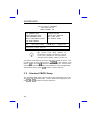
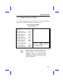
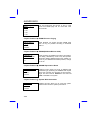
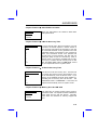
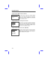
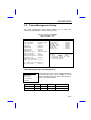
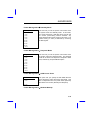
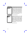
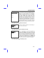
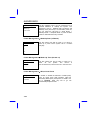
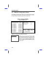
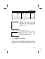
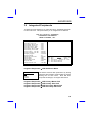
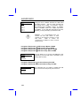
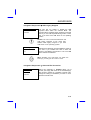
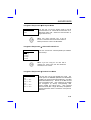
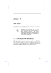
Chapter 3
Award BIOS
This chapter tells how to configure the system parameters. You may update
your BIOS via AWARD Flash Utility.
Important: Because the BIOS code is the most
often changed part of the mainboard design, the
BIOS information contained in this chapter
(especially the Chipset Setup parameters) may be
a little different compared to the actual BIOS that
came with your mainboard.
3.1
Entering the Award BIOS Setup Menu
The BIOS setup utility is a segment of codes/routines residing in the BIOS
Flash ROM. This routine allows you to configure the system parameters and
save the configuration into the 128 byte CMOS area, (normally in the RTC
chip or directly in the main chipset). To enter the BIOS Setup, press
during POST (Power-On Self Test). The BIOS Setup Main Menu appears as
follows.
3-1
AWARD BIOS
ROM PCI/ISA BIOS (XXXXXXXX)
CMOS SETUP UTILITY
AWARD SOFTWARE, INC.
STANDARD CMOS SETUP
BIOS FEATURES SETUP
CHIPSET FEATURES SETUP
POWER MANAGEMENT SETUP
PNP/PCI CONFIGURATION SETUP
LOAD SETUP DEFAULTS
LOAD TURBO DEFAULTS
ESC
F10
:
:
Quit
Save & Exit Setup
INTEGRATED PERIPHRALS
PASSWORD SETTING
IDE HDD AUTO DETECTION
SAVE & EXIT SETUP
EXIT WITHOUT SAVING
:
(Shift) F2
:
Select Item
Change Color
Description of each function
Tip: Choose "Load Setup Defaults" for
recommended optimal performance. Choose
"Load Turbo Defaults" for best performance
with light system loading. Refer to section 3.7.
The section at the bottom of the screen tells how to control the screen. Use
the arrow keys to move between items,
to color scheme of the
to exit, and
to save the changes before exit. Another section
display,
at the bottom of the screen displays a brief description of the highlighted item.
After selecting an item, press
3.2
to select or enter a submenu.
Standard CMOS Setup
The "Standard CMOS Setup" sets the basic system parameters such as the
date, time, and the hard disk type. Use the arrow keys to highlight an item
or
to select the value for each item.
and
3-2
AWARD BIOS
ROM PCI/ISA BIOS (XXXXXXXX)
STANDARD CMOS SETUP
AWARD SOFTWARE, INC.
Date (mm:dd:yy)
Time (hh:mm:ss)
HARD DISK
Primary Master :
Primary Slave
:
Secondary Master:
Secondary Slave :
TYPE
Auto
Auto
Auto
Auto
:
:
Wed. Mar
00:00:00
SIZE
0
0
0
0
Drive A :
Drive B :
1.44M, 3.5 in
None
Video
:
Halt On :
EGA/VGA
All Errors
ESC
F10
:
:
Quit
Save & Exit Setup
Standard CMOS
CYLS
0
0
0
0
6
1996
HEAD
0
0
0
0
PRECOMP
0
0
0
0
LANDZ
0
0
0
0
MODE
AUTO
AUTO
AUTO
AUTO
Base Memory :
640 K
Extended Memory:
15360 K
Other Memory :
384 K
Total Memory :
16384 K
(Shift) F2
: Select Item
: Change Color
Date
To set the date, highlight the Date parameter. Press
current date. The date format is month, date, and year.
Standard CMOS
SECTORS
0
0
0
0
or
to set the
Time
To set the time, highlight the Time parameter. Press
or
to set the
current time in hour, minute, and second format. The time is based on the 24
hour military clock.
3-3
AWARD BIOS
Standard CMOS
Standard CMOS
Standard CMOS
Standard CMOS
Type
Auto
User
None
1
2
...
45
Primary Master Type
Primary Slave Type
Secondary Master Type
Secondary Slave Type
This item lets you select the IDE hard disk parameters
that your system supports. These parameters are Size,
Number of Cylinder, Number of Head, Start Cylinder for
Pre-compensation, Cylinder number of Head Landing
Zone and Number of Sector per Track. The default
setting is Auto, which enables BIOS to automatically
detect the parameters of installed HDD at POST (PowerOn Self Test). If you prefer to enter HDD parameters
manually, select User. Select None if no HDD is
connected to the system.
The IDE CDROM is always automatically detected.
Tip: For an IDE hard disk, we recommend that
you use the "IDE HDD Auto Detection" to
enter the drive specifications automatically.
See the section "IDE HDD Auto Detection".
Standard CMOS
Standard CMOS
Standard CMOS
Standard CMOS
Mode
Auto
Normal
LBA
Large
3-4
Primary Master Mode
Primary Slave Mode
Secondary Master Mode
Secondary Slave Mode
The enhanced IDE feature allows the system to use a
hard disk with a capacity of more than 528MB. This is
made possible through the Logical Block Address (LBA)
mode translation. The LBA is now considered as a
standard feature of current IDE hard disk on the market
because of its capability to support capacity larger than
528MB. Note that if HDD is formatted with LBA On, it
will not be able to boot with LBA Off.
AWARD BIOS
Standard CMOS
Standard CMOS
Drive A
None
360KB 5.25"
1.2MB 5.25"
720KB 3.5"
1.44MB 3.5"
2.88MB 3.5"
These items select floppy drive type. The available settings
and types supported by the mainboard are listed on the left.
Standard CMOS
Video
EGA/VGA
CGA40
CGA80
Mono
Drive A
Drive B
Video
This item specifies the type of video card in use. The
default setting is VGA/EGA . Since current PCs use
VGA only, this function is almost useless and may be
disregarded in the future.
Standard CMOS
Halt On
Halt On
No Errors
All Errors
All, But Keyboard
All, But Diskette
All, But Disk/Key
This parameter enables you to control the system stops in
case of Power-On Self Test (POST) error.
3-5
AWARD BIOS
3.3
BIOS Features Setup
This screen appears when you select the option "BIOS Features Setup" from
the main menu.
ROM PCI/ISA BIOS (XXXXXXXX)
BIOS FEATURES SETUP
AWARD SOFTWARE, INC.
Virus Warning
External Cache
Quick Power On Self Test
Boot Sequence
Swap Floppy Drive
Boot Up Floppy Seek
Boot Up NumLock Status
Boot Up System Speed
Typematic Rate Setting
:
:
:
:
:
:
:
:
:
Disabled
Enabled
Enabled
A,C,SCSI
Disabled
Disabled
ON
High
Disabled
Video BIOS Shadow
C8000-CBFFF Shadow
CC000-CFFFF Shadow
D0000-D3FFF Shadow
D4000-D7FFF Shadow
D8000-DBFFF Shadow
DC000-DFFFF Shadow
Typematic Rate (Chars/Sec)
Typematic Delay (Msec)
Security Option
PCI/VGA Palette Snoop
OS Select for DRAM > 64MB
:
:
:
:
:
6
250
Setup
Disabled
Non-OS/2
ESC:
F1 :
F5 :
F6 :
F7 :
BIOS Features
Virus Warning
Enabled
Disabled
:
:
:
:
:
:
:
Enabled
Disabled
Disabled
Disabled
Disabled
Disabled
Disabled
: Select Item
Quit
Help
PU/PD/+/- : Modify
Old Values
(Shift) F2 : Color
Load Setup Defaults
Load Turbo Defaults
Virus Warning
Set this parameter to Enabled to activate the warning
message. This feature protects the boot sector and partition
table of your hard disk from virus intrusion.
Any attempt during boot up to write to the boot sector of the
hard disk drive stops the system and the following warning
message appears on the screen. Run an anti-virus program
to locate the problem.
! WARNING !
Disk Boot Sector is to be modified
Type "Y" to accept write, or "N" to abort write
Award Software, Inc.
3-6
AWARD BIOS
BIOS Features
External Cache
Enabled
Disabled
BIOS Features
Quick Power-on
Self-test
Enable
Disabled
BIOS Features
Boot Sequence
A,C,SCSI
C,A,SCSI
C,CDROM,A
CDROM,C,A
D,A,SCSI
E,A,SCSI
F,A,SCSI
SCSI,A,C
SCSI,C,A
C only
BIOS Features
Swap Floppy Drive
Enabled
Disabled
BIOS Features
External Cache
Enabling this parameter activates the secondary cache
(currently, PBSRAM cache). Disabling the parameter
slows down the system. Therefore, we recommend that
you leave it enabled unless you are troubleshooting a
problem.
Power-On Self-Test
This parameter speeds up POST by skipping some items
that are normally checked.
Boot Sequence
This parameter allows you to specify the system boot up
search sequence. The hard disk ID are listed below:
C: Primary master
D: Primary slave
E: Secondary master
F: Secondary slave
Swap Floppy Drive
This item allows you to swap floppy drives. For example,
if you have two floppy drives (A and B), you can assign
the first drive as drive B and the second drive as drive A or
vice-versa.
Boot-up Floppy Seek
3-7
AWARD BIOS
Boot-up Floppy
Seek
Enabled
Disabled
BIOS Features
Boot-up NumLock
Status
On
Off
BIOS Features
Boot-up System
Speed
High
Low
BIOS Features
Typematic Rate
Setting
Enabled
Disabled
BIOS Features
Typematic Rate
6
8
10
12
15
20
24
30
3-8
When enabled, the BIOS issues the seek command to
the floppy drive during POST to move floppy drive head
forward and backward.
Boot-up NumLock Status
Setting this parameter to On enables the numeric function
of the numeric keypad. Set this parameter to Off to
disregard the function. Disabling the numeric function
allows you to use the numeric keypad for cursor control.
Boot-up System Speed
Select High or Low system speed after boot.
Typematic Rate Setting
Set this parameter to Enable/Disable the keyboard
repeat function. When enabled, continually holding down
a key on the keyboard will generate repeatedly
keystrokes.
Typematic Rate
This item allows you to control the speed of repeated
keystrokes.
The
default
is
30
characters/sec .
AWARD BIOS
BIOS Features
Typematic Delay
250
500
750
1000
BIOS Features
Security Option
Setup
System
Typematic Delay
This parameter allows you to control the delay time
between the first and the second keystroke (where the
repeated keystrokes begin).
The typematic delay
settings are 250, 500, 750, and 1000 msec.
Security Option
The System option limits access to both the System boot
and BIOS setup. A prompt asking you to enter your
password appears on the screen every time you boot the
system.
The Setup option limits access only to BIOS setup.
To disable the security option, select Password Setting
from the main menu, don't type anything and just press
<Enter>.
BIOS Features
PCI/VGA Palette
Snoop
Enabled
Disabled
BIOS Features
OS Select for
DRAM > 64MB
OS/2
Non-OS/2
PCI/VGA Palette Snoop
Enabling this item informs the PCI VGA card to keep
silent (and to prevent conflict) when palette register is
updated (i.e., accepts data without responding any
communication signals). This is useful only when two
display cards use the same palette address and plugged
in the PCI bus at the same time (such as MPEQ or
Video capture). In such case, PCI VGA is silent while
MPEQ/Video capture is set to function normally.
OS Select for DRAM > 64MB
Set to OS/2 if your system is utilizing an OS/2
operating system and has a memory size of more
than 64 MB.
3-9
AWARD BIOS
BIOS Features
Video BIOS
Shadow
Enabled
Disabled
BIOS Features
BIOS Features
BIOS Features
BIOS Features
BIOS Features
BIOS Features
C8000-CBFFF
Shadow
Enabled
Disabled
Video BIOS Shadow
VGA BIOS Shadowing means to copy video display
card BIOS into the DRAM area. This enhances system
performance because DRAM access time is faster than
ROM.
C800-CBFF Shadow
CC00-CFFF Shadow
D000-D3FF Shadow
D400-D7FF Shadow
D800-DBFF Shadow
DC00-DFFF Shadow
These six items are for shadowing ROM code on other
expansion cards. Before you set these parameters, you
need to know the specific addresses of that ROM code.
If you do not know this information, enable all the ROM
shadow settings.
Note: The F000 and E000 segments are
always shadowed because BIOS code
occupies these areas.
3-10
AWARD BIOS
3.4
Chipset Features Setup
The "Chipset Features Setup" includes settings for the chipset dependent
features. These features are related to system performance.
ROM PCI/ISA BIOS (XXXXXXXX)
CHIPSET FEATURES SETUP
AWARD SOFTWARE, INC.
Auto Configuration
DRAM Timing
: Enabled
: 60 ns
DRAM Leadoff Timing
DRAM Read Burst (EDO/FP)
DRAM Write Burst Timing
Fast EDO Lead Off
Refresh RAS# Assertion
DRAM Page Idle Timer
DRAM Enhanced Paging
Fast MA to RAS# Delay
SDRAM(CAS Lat/RAS-to-CAS)
SDRAM Speculative Read
System BIOS Cacheable
Video BIOS Cacheable
:
:
:
:
:
:
:
:
:
:
:
:
8 Bit I/O Recovery Time
16 Bit I/O Recovery Time
Memory Hole At 15M-16M
PCI Passive Release
PCI Delayed Transaction
Mem. Drive Str.(MA/RAS)
10/6/3/3
x222/x333
x222
Disabled
5 Clks
2 Clks
Enabled
2 Clks
3/3
Disabled
Enabled
Enabled
: 4
: 1
: Disabled
: Disabled
: Disabled
: 16mA/16mA
ESC:
F1 :
F5 :
F6 :
F7 :
: Select Item
Quit
Help
PU/PD/+/- : Modify
Old Values
(Shift) F2 : Color
Load Setup Defaults
Load Turbo Defaults
Caution: Make sure you fully understand the
items contained in this menu before you try to
change anything.
You may change the
parameter settings to improve system
performance . However, it may cause system
unstable if the setting are not correct for your
system configuration.
3-11
AWARD BIOS
Chipset Features
Auto Configuration
Auto Configuration
Enabled
Disabled
When Enabled, the DRAM and cache related timing
are set to pre-defined value according to CPU type
and clock. Select Disable if you want to specify your
own DRAM timing.
Chipset Features
DRAM Timing
DRAM Timing
60 ns
70 ns
There to sets of DRAM timing parameters can be
automatically set by BIOS, 60ns and 70ns.
Warning: The default memory timing setting is
60ns to get the optimal performance. Because
the specification limitation of INTEL TX chipset
, 70ns SIMM can only be used with CPU
external clock 60MHz. To use 70ns SIMM
with 66MHz CPU external clock may result in
unstable system behavior.
Chipset Features
DRAM Leadoff Timing
DRAM Leadoff
Timing
11/7/3/4
10/6/3/3
11/7/4/4
10/6/4/3
The Leadoff means the timing of first memory cycle in
the burst read or write. Actually, this item controls
only page miss read/write leadoff timing and the
clocks of RAS precharge and RAS to CAS delay. The
four digital represent Read Leadoff/ Write Leadoff/
RAS Precharge/ RAS to CAS delay. For example,
default is 10/6/3/3, which means you have 10-x-x-x
DRAM page miss read and 6-x-x-x DRAM write, with
3 clocks RAS precharge and 3 clocks RAS to CAS
delay.
Chipset Features
DRAM Read Burst (EDO/FP)
3-12
AWARD BIOS
DRAM Read Burst
(EDO/FP)
x444/x444
x333/x444
x222/x333
Read Burst means to read four continuous memory
cycles on four predefined addresses from the DRAM.
The default value is x222/x333 for 60ns EDO or FPM
(Fast Page Mode) DRAM. Which means the 2nd,3rd
and 4th memory cycles are 2 CPU clocks for EDO
and 3 clocks for FPM. The value of x is the timing of
first memory cycle and depends on the "DRAM
Leadoff Timing" setting.
Chipset Features
DRAM Write Burst Timing
DRAM Write Burst
Timing
x444
x333
x222
Write Burst means to write four continuous memory
cycles on four predefined addresses to the DRAM.
This item sets the DRAM write timing of the 2nd,3rd
and 4th memory cycles. There is no difference of
EDO and FPM DRAM on the write burst timing. The
value of x depends on the "DRAM Leadoff Timing"
setting.
Chipset Features
Fast EDO Lead Off
Fast EDO Lead Off
Enabled
Disabled
This item enables fast EDO read timing, results 1
clock pull-in for read leadoff latency of EDO read
cycles. It must be Disabled, if any FPM DRAM is
installed.
Chipset Features
Refresh RAS# Assertion
Refresh RAS#
Assertion
5 Clks
4 Clks
This item controls the number of clocks RAS is
asserted for refresh cycle.
Chipset Features
DRAM Page Idle Timer
3-13
AWARD BIOS
DRAM Page Idle
Timer
2 Clks
4 Clks
6 Clks
8 Clks
This item determines the amount of time in CPU
clocks that DRAM page will be close after CPU
becomes idle.
Chipset Features
DRAM Enhance Paging
DRAM Enhance
Paging
Enabled
Disabled
When Enabled, TX chipset will keep DRAM page
open as long as possible according to enhanced
method.
Chipset Features
SDRAM(CASLat/RAS-to-CAS)
SDRAM(CAS
Lat/RAS-to-CAS)
2/2
3/3
These are timing of SDRAM CAS Latency and RAS to
CAS Delay, calculated by clocks. They are important
parameters affects SDRAM performance, default is 2
clocks. If your SDRAM has unstable problem, change
2/2 to 3/3.
Chipset Features
SDRAM Speculative Read
SDRAM Speculative
Read
Enabled
Disabled
Enable this item reduce one clock of SDRAM read
leadoff timing by presenting the SDRAM read request
before the controller chip decodes the final memory
target. This Item must be Disabled if more than one
DIMM is installed in the system.
Chipset Features
System BIOS Cacheable
System BIOS
Cacheable
Enabled
Disabled
Enabling this item allows you to cache the system
BIOS to further enhance system performance.
3-14
AWARD BIOS
Chipset Features
Video BIOS Cacheable
Video BIOS
Cacheable
Enabled
Disabled
Allows the video BIOS to be cached to allow faster
video performance.
Chipset Features
8 Bit I/O Recovery Time
8 Bit I/O Recovery
Time
For some old I/O chips, after the execution of an I/O
command, the device requires a certain amount of
time (recovery time) before the execution of the next
I/O command. Because of new generation CPU and
mainboard chipset, the assertion of I/O command is
faster, and sometimes shorter than specified I/O
recovery time of old I/O devices. This item lets you
specify the delay of 8-bit I/O command by count of
ISA bus clock. If you find any unstable 8-bit I/O card,
you may try to extend the I/O recovery time via this
item. The BIOS default value is 4 ISA clock. If set to
NA, the chipset will insert 3.5 system clocks.
1
2
3
4
5
6
7
8
NA
Chipset Features
16 Bit I/O Recovery Time
16 Bit I/O Recovery
Time
1
2
3
4
NA
The same as 16-bit I/O recovery time. This item lets
you specify the recovery time for the execution of 16bit I/O commands by count of ISA bus clock. If you
find any of the installed 16-bit I/O cards unstable, try
extending the I/O recovery time via this item. The
BIOS default value is 1 ISA clocks . If set to NA, the
chipset will automatically insert 3.5 system clocks.
Chipset Features
Memory Hole At 15M-16M
Memory Hole At
15M-16M
Enabled
Disabled
This option lets you reserve system memory area for
special ISA cards. The chipset accesses code/data of
these areas from the ISA bus directly. Normally,
these areas are reserved for memory mapped I/O
card.
3-15
AWARD BIOS
Chipset Features
PCI Passive Release
PCI Passive Release
Enabled
Disabled
This item lets you control the Passive Release
function of the PIIX4 chipset (Intel PCI to ISA bridge).
This function is used to meet latency of ISA bus
master. Try to enable or disable it, if you have ISA
card compatibility problem.
Chipset Features
PCI Delayed Transaction
PCI Delayed
Transaction
Enabled
Disabled
This item lets you control the Delayed Transaction
function of the PIIX4 chipset (Intel PCI to ISA bridge).
This function is used to meet latency of PCI cycles to
or from ISA bus. Try to enable or disable it, if you
have ISA card compatibility problem.
Chipset Features
Mem. Drive Str. (MA/RAS)
Mem. Drive Str.
(MA/RAS)
10mA/10mA
10mA/16mA
16mA/10mA
16mA/16mA
This option controls the driving strength of memory
address and control signals. It is recommended to
use less driving current for light memory loading, to
prevent undershoot or overshoot.
3-16
AWARD BIOS
3.5
Power Management Setup
The Power Management Setup screen enables you to control the
mainboard ’s green features. See the following screen.
ROM PCI/ISA BIOS (XXXXXXXX)
POWER MANAGEMENT SETUP
AWARD SOFTWARE, INC.
Power Management
PM Control by APM
Video Off Method
Video Off After
:
:
:
:
Disabled
Yes
V/H SYNC + Blank
Suspend
Doze Mode
Standby Mode
Suspend Mode
HDD Power Down
Modem WakeUp
Suspend Mode Option
:
:
:
:
:
:
Disabled
Disabled
Disabled
Disabled
Disabled
Power On Suspend
Throttle Duty Cycle
:
VGA Active Monitor
:
Power Bottom Override :
RTC WakeUp timer
:
WakeUp Date (of Month):
WakeUp Time (hh:mm:ss):
62.5%
Disabled
Disabled
Disabled
0
07:00:00
** Reload Global Timer Events **
IRQ [3-7,9-15],NMI
: Enabled
Primary IDE 0
: Disabled
Primary IDE 1
: Disabled
Secondary IDE 0
: Disabled
Secondary IDE 1
: Disabled
Floppy Disk
: Disabled
Serial Port
: Disabled
Parallel Port
: Disabled
ESC:
F1 :
F5 :
F6 :
F7 :
Quit
: Select Item
Help
PU/PD/+/- : Modify
Old Values (Shift) F2 : Color
Load Setup Defaults
Load Turbo Defaults
**
Break event From Suspend
**
IRQ 8 Clock Event
: Disabled
Power Management
Power Management
Max Saving
Mix Saving
User Defined
Disabled
Mode
Min Saving
Max Saving
Doze
1 hour
1 min
Power Management
This function allows you to set the default parameters
of power-saving modes. Set to Disable to turn off
power management function. Set to User Defined to
choose your own parameters.
Standby
1 hour
1 min
Suspend
1 hour
1 min
HDD Power Down
15 min
1 min
3-17
AWARD BIOS
Power Management
PM Controlled by
APM
Yes
No
If "Max Saving" is selected, you can turn on this item,
transfer power management control to APM
(Advanced Power Management) and enhance power
saving function. For example, stop CPU internal
clock.
Power Management
Video Off Method
Blank Screen
V/H SYNC+Blank
DPMS
Disabled
1 Min
2 Min
4 Min
8 Min
12 Min
20 Min
30 Min
40 Min
1 Hour
3-18
Video Off After
To turn off video monitor at which power down mode.
Power Management
Doze Mode
Video Off Method
This determines the way that monitor is off. Blank
Screen writes blanks to video buffer. V/H
SYNC+Blank allows BIOS to control VSYNC and
HSYNC signals. This function applies only for DPMS
(Display Power Management Standard) monitor. The
DPMS mode uses DPMS function provided by VGA
card.
Power Management
Video Off After
N/A
Doze
Standby
Suspend
PM Controlled by APM
Doze Mode
This item lets you set the period of time after which
the system enters into Doze mode. In this mode, the
CPU clock slows down. The ratio is specified in the
"Throttle Duty Cycle". Any activity detected returns the
system to full power. The system activity (or event) is
detected by monitoring the IRQ signals.
AWARD BIOS
Power Management
Standby Mode
Disabled
1 Min
2 Min
4 Min
8 Min
12 Min
20 Min
30 Min
40 Min
1 Hour
This item lets you set the period of time after which
the system enters into Standby mode. In this mode,
CPU clock slows down, hard disk will be shut off and
the monitor power-saving feature activates. Any
activity detected returns the system to full power. The
system activity (or event) is detected by monitoring
the IRQ signals.
Power Management
Suspend Mode
Disabled
1 Min
2 Min
4 Min
8 Min
12 Min
20 Min
30 Min
40 Min
1 Hour
Disabled
1 Min
.....
15 Min
Suspend Mode
This item lets you set the period of time after which
the system enters into Suspend mode. The Suspend
mode can be Power On Suspend or Suspend to Hard
Drive, selected by "Suspend Mode Option".
Power Management
HDD Power Down
Standby Mode
HDD Power Down
This option lets you specify the IDE HDD idle time
before the device enters the power down state. This
item is independent from the power states previously
described in this section (Standby and Suspend).
Power Management
Modem WakeUp
3-19
AWARD BIOS
Modem WakeUp
Disabled
Enabled
This mainboard implements AOpen special circuit
(patent applied) to detect modem ring signal and
wakeup from soft power off. The most possible
applications are automatic answering machine and
fax send/receive. It does not like traditional green PC
suspend mode, the system can be true power off,
(identified by the fan of your power supply is off). You
can use external box modem or AOpen MP32/F34I
internal modem card for modem ring-on, but
MP32/F34I is recommended, since MP32/F34I has
special circuit to cooperate with this mainboard and
the modem power and system power can be off
together. For detail of how to use modem ring-on,
refer to section 3-17 "Modem Wake Up".
Power Management
Suspend Mode
Option
Power On Suspend
Suspennd to Hard Drive
You can select suspend mode by this item. Power
On Suspend is the traditional Green PC suspend
mode, the CPU clock is stop, all other devices are
shut off. But power must be kept On to detect
activities from modem, keyboard/mouse and returns
the system to full power. The system activities is
detected by monitoring the IRQ signals. Suspend to
Hard Drive saves system status, memory and screen
image into hard disk, then the power can be totally
Off. Next time, when power is turned On, the system
goes back to your original work within just few
seconds. You need utility ZVHDD to reserve disk
space. Refer to section 3.16 "Suspend to Hard Drive"
for more information".
Power Management
3-20
Suspend Mode Option
Throttle Duty Cycle
AWARD BIOS
Throttle Duty Cycle
12.5 %
25.0 %
37.5 %
50.0 %
62.5 %
75.0 %
87.5 %
Clock Throttling means at the Doze/Standby state, the
CPU clock count in a given time (not the frequency) is
reduced to the ratio specified in this parameter.
Actually, the period per CPU clock is not changed.
For example, a 66MHz CPU clock remains the same
30ns clock period when system goes into
Doze/Suspend. The chipset generates the STPCLK
(stop clock) signal periodically to prevent CPU for
accepting clock from clock generator. For full power
on, the CPU can receive 66M count in one second. If
the Slow Clock Ratio is set to 50%, the CPU will only
receive 33M clock count in one second. This will
effectively reduce CPU speed as well as CPU power.
Power Management
VGA Activity
Monitor
Enabled
Disabled
To enable or disable the detection of VGA activity for
power down state transition.
Power Management
Power Bottom
Override
Disabled
Enabled
VGA Active Monitor
Power Bottom Override
This is a specification of ACPI and supported by
hardware. When Enabled, the soft power switch on the
front panel can be used to control power On, Suspend
and Off. If the switch is pressed less than 4 sec during
power On, the system will go into Suspend mode. If
the switch is pressed longer than 4 sec, the system will
be turned Off. The default setting is Disabled, soft
power switch is only used to control On and Off, there
is no need to press 4 sec, and there is no Suspend.
Power Management
RTC WakeUp Timer
3-21
AWARD BIOS
RTC WakeUp Timer
Disabled
Wake Up
Power Off
The RTC WakeUp Timer can be programmed at a
specified date/time to wakeup the system. The
Date/Time is set by " WakeUp Date (of Month)" and
"WakeUp Time ( hh:mm:ss)". For automatic power off,
you can select the idle timer in "Doze Mode" +
"Standby Mode" + "Suspend Mode" to power off after
system is detected without any activities.
Power Management
Date (of Month)
Alarm
0
1
2
......
30
31
This item selects the date of month to on which to
wake up or power off the system. Set to 0 means
everyday.
Power Management
Time (hh:mm:ss)
Alarm
07:00:00
.. : .. : ..
3-22
Wake Up Time (hh:mm:ss)
This item selects the time at which to wake up or
power
off
the
system.
The
format
is
hour:minute:second, note that hour is in 24 hours form.
Power Management
IRQ 8 Clock Event
Enabled
Disabled
WakeUp Date (of Month)
IRQ 8 Clock Event
To enable or disable the detection of IRQ8 (RTC)
event for power down state transition. OS2 has
periodically IRQ8 (RTC) interruptions, If IRQ8 is not
set to Disabled, OS/2 may fail to go into
Doze/Standby/Suspend mode.
AWARD BIOS
Power Management
IRQ [3-7,9-15],NMI
IRQ [3-7,9-15],NMI To enable or disable the detection of IRQ3-7, IRQ9Enabled
Disabled
15 or NMI interrupt events for power down state
transition.
Power Management
Power Management
Power Management
Power Management
Power Management
Power Management
Power Management
Primary IDE 0
Enabled
Disabled
Primary IDE 0
Primary IDE 1
Secondary IDE 0
Secondary IDE 1
Floppy Disk
Serial Port
Parallel Port
These items enable or disable the detection of IDE,
floppy, serial and parallel port activities for power
down state transition. Actually it detects the read/write
to/from I/O or address port.
3-23
AWARD BIOS
3.6
PNP/PCI Configuration Setup
The PNP/PCI Configuration Setup allows you to configure the ISA and PCI
devices installed in your system. The following screen appears if you select
the option "PNP/PCI Configuration Setup" from the main menu.
ROM PCI/ISA BIOS (XXXXXXXX)
PNP/PCI CONFIGURATION SETUP
AWARD SOFTWARE, INC.
PnP OS Installed
:
Resources Controlled By :
Reset Configuration Data :
No
Manual
Disabled
IRQ
IRQ
IRQ
IRQ
IRQ
IRQ
IRQ
IRQ
IRQ
IRQ
3 assigned to
4 assigned to
5 assigned to
7 assigned to
9 assigned to
10 assigned to
11 assigned to
12 assigned to
14 assigned to
15 assigned to
:
:
:
:
:
:
:
:
:
:
PCI/ISA
PCI/ISA
PCI/ISA
PCI/ISA
PCI/ISA
PCI/ISA
PCI/ISA
PCI/ISA
PCI/ISA
PCI/ISA
PnP
PnP
PnP
PnP
PnP
PnP
PnP
PnP
PnP
PnP
DMA
DMA
DMA
DMA
DMA
DMA
0
1
3
5
6
7
:
:
:
:
:
:
PCI/ISA
PCI/ISA
PCI/ISA
PCI/ISA
PCI/ISA
PCI/ISA
PnP
PnP
PnP
PnP
PnP
PnP
assigned
assigned
assigned
assigned
assigned
assigned
to
to
to
to
to
to
PNP/PCI Configuration
PnP OS Installed
Yes
No
3-24
PCI IDE IRQ Map To
Primary IDE INT#
Secondary IDE INT#
Used MEM base addr
Used MEM Length
ESC:
F1 :
F5 :
F6 :
F7 :
:
:
:
:
:
PCI-Auto
A
B
N/A
8K
: Select Item
Quit
Help
PU/PD/+/- : Modify
Old Values
(Shift) F2 : Color
Load Setup Defaults
Load Turbo Defaults
PnP OS Installed
Normally, the PnP resources are allocated by BIOS
during POST (Power-On Self Test). If you are using
a PnP operating system (such as Windows 95), set
this item to Yes to inform BIOS to configure only the
resources needed for booting (VGA/IDE or SCSI).
The rest of system resources will be allocated by PnP
operating system.
AWARD BIOS
PNP/PCI Configuration
Resources Controlled
by
Auto
Manual
Setting this option to Manual allows you to
individually assign the IRQs and DMAs to the ISA and
PCI devices. Set this to Auto to enable the autoconfiguration function.
PNP/PCI Configuration
Reset Configuration
Data
Enabled
Disabled
Reset Configuration Data
In case conflict occurs after you assign the IRQs or
after you configure your system, you can enable this
function, allow your system to automatically reset
your configuration and reassign the IRQs.
PNP/PCI Configuration
PNP/PCI Configuration
PNP/PCI Configuration
PNP/PCI Configuration
PNP/PCI Configuration
PNP/PCI Configuration
PNP/PCI Configuration
PNP/PCI Configuration
PNP/PCI Configuration
PNP/PCI Configuration
IRQ 3
Legacy ISA
PCI/ISA PnP
Resources Controlled By
IRQ3 (COM2)
IRQ4 (COM1)
IRQ5 (Network/Sound or Others)
IRQ7 (Printer or Others)
IRQ9 (Video or Others)
IRQ10 (SCSI or Others)
IRQ11 (SCSI or Others)
IRQ12 (PS/2 Mouse)
IRQ14 (IDE1)
IRQ15 (IDE2)
If your ISA card is not PnP compatible and requires a
special IRQ to support its function, set the selected
IRQ to Legacy ISA . This setting informs the PnP
BIOS to reserve the selected IRQ for the installed
legacy ISA card. The default is PCI/ISA PnP . Take
note that PCI cards are always PnP compatible
(except old PCI IDE card).
3-25
AWARD BIOS
PNP/PCI Configuration
PNP/PCI Configuration
PNP/PCI Configuration
PNP/PCI Configuration
PNP/PCI Configuration
PNP/PCI Configuration
DMA 0
Legacy ISA
PCI/ISA PnP
If your ISA card is not PnP compatible and requires a
special DMA channel to support its function, set the selected
DMA channel to Legacy ISA . This setting informs the PnP
BIOS to reserve the selected DMA channel for the installed
legacy ISA card. The default is PCI/ISA PnP . Take note
that PCI card does not require DMA channel.
PNP/PCI Configuration
PCI IDE IRQ Map
To
ISA
PCI-Slot1
PCI-Slot2
PCI-Slot3
PCI-Slot4
PCI-Auto
3-26
PCI IDE IRQ Map To
Some old PCI IDE add-on cards are not fully PnP
compatible. These cards require you to specify the
slot in use to enable BIOS to properly configure the
PnP resources. This function allows you to select the
PCI slot for any PCI IDE add-on card present in your
system. Set this item to Auto to allow BIOS to
automatically configure the installed PCI IDE card(s).
PNP/PCI Configuration
PNP/PCI Configuration
Primary IDE INT#
A
B
C
D
DMA 0
DMA 1
DMA 3
DMA 5
DMA 6
DMA 7
Primary IDE INT#
Secondary IDE INT#
These two items, in conjunction with item "PCI IDE
IRQ Map To", specify the IRQ routing of the primary
or secondary channel of the PCI IDE add-on card (not
the onboard IDE). Each PCI slot has four PCI
interrupts aligned as listed in the table below. You
must specify the slot in the "PCI IDE IRQ Map To",
and set the PCI interrupt ( INTx) here according to the
interrupt connection on the card.
AWARD BIOS
PCI Slot
Slot 1
Slot 2
Slot 3
Slot 4
Slot 5 (if any)
Location 1
(pin A6)
INTA
INTB
INTC
INTD
INTD
PNP/PCI Configuration
Used MEM base addr
N/A
C800
CC00
D000
D400
D800
DC00
3.7
Location 3
(pin A7)
INTC
INTD
INTA
INTB
INTB
Location 4
(pin B8)
INTD
INTA
INTB
INTC
INTC
Used MEM BaseAddr
This item, in conjunction with the "Used MEM
Length", lets you set a memory space for non-PnP
compatible ISA card.
This item specifies the
memory base (start address) of the reserved
memory space. The memory size is specified in the
"Used MEM Length".
PNP/PCI Configuration
Used MEM Length
8K
16K
32K
64K
Location 2
(pin B7)
INTB
INTC
INTD
INTA
INTA
Used MEM Length
If your ISA card is not PnP compatible and requires
special memory space to support its function,
specify the memory size in this parameter to inform
the PnP BIOS to reserve the specified memory
space for installed legacy ISA card.
Load Setup Defaults
The "Load Setup Defaults" option loads optimized settings for optimum
system performance. Optimal settings are relatively safer than the Turbo
settings. We recommend you to use the Optimal settings if your system has
large memory size and fully loaded with add-on card (for example, a file
server using double-sided 8MB SIMM x4 and SCSI plus Network card
occupying the PCI and ISA slots).
3-27
AWARD BIOS
Optimal is not the slowest setting for this mainboard. If you need to verify a
unstable problem, you may manually set the parameter in the "BIOS Features
Setup" and "Chipset Features Setup" to get slowest and safer setting.
3.8
Load Turbo Defaults
The "Load Turbo Defaults" option gives better performance than Optimal
values. However, Turbo values may not be the best setting of this mainboard
but these values are qualified by the AOpen RD and QA department as the
reliable settings especially if you have limited loading of add-on card and
memory size (for example, a system that contains only a VGA/Sound card
and two SIMMs).
To attain the best system performance, you may manually set the parameters
in the "Chipset Features Setup" to get proprietary setting. Make sure that you
know and understand the functions of every item in Chipset Setup menu. The
performance difference of Turbo from Optimal is normally around 3% to 10%,
depending on the chipset and the application.
3-28
AWARD BIOS
3.9
Integrated Peripherals
The following screen appears if you select the option "Integrated Peripherals"
from the main menu. This option allows you to configure the I/O features.
ROM PCI/ISA BIOS (XXXXXXXX)
INTEGRATED PERIPHERALS
AWARD SOFTWARE, INC.
IDE HDD Block Mode:
IDE Primary Master PIO
IDE Primary Slave PIO
IDE Secondary Master PIO
IDE Secondary Slave PIO
IDE Primary Master UDMA
IDE Primary Slave UDMA
IDE Secondary Master UDMA
IDE Secondary Slave UDMA
On-Chip Primary
PCI-IDE
On-Chip Secondary PCI-IDE
USB Legacy Support
USB IRQ Released
:
:
:
:
:
:
:
:
:
:
:
:
:
Enabled
Auto
Auto
Auto
Auto
Auto
Auto
Auto
Auto
Enabled
Enabled
Disabled
No
Onboard FDC Controller
Onboard UART 1
Onboard UART 2
Onboard UART 2 Mode
IR Duplex Mode
Onboard Parallel Port
:
:
:
:
:
:
Enabled
AUTO
AUTO
Standard
Half
378/IRQ7
Integrated Peripherals
IDE HDD Block
Mode
Enabled
Disabled
Parallel Port Mode
ECP Mode Use DMA
ESC:
F1 :
F5 :
F6 :
F7 :
: Normal
: 3
: Select Item
Quit
Help
PU/PD/+/- : Modify
Old Values
(Shift) F2 : Color
Load Setup Defaults
Load Turbo Defaults
IDE HDD Block Mode
This feature enhances disk performance by allowing
multisector data transfers and eliminates the interrupt
handling time for each sector. Most IDE drives,
except with old designs, can support this feature.
Integrated Peripherals
Integrated Peripherals
Integrated Peripherals
Integrated Peripherals
IDE Primary Master PIO
IDE Primary Slave PIO
IDE Secondary Master PIO
IDE Secondary Slave PIO
3-29
AWARD BIOS
IDE Primary Master
PIO
Auto
Mode 1
Mode 2
Mode 3
Mode 4
Setting this item to Auto activates the HDD speed
auto-detect function. The PIO mode specifies the
data transfer rate of HDD. For example: mode 0
data transfer rate is 3.3MB/s, mode 1 is 5.2MB/s,
mode 2 is 8.3MB/s, mode 3 is 11.1MB/s and mode 4
is 16.6MB/s. If your hard disk performance becomes
unstable, you may manually try the slower mode.
Caution: It is recommended that you
connect the first IDE device of each
channel to the endmost connector of the
IDE cable.
Refer to section 2.3
"Connectors" for details on how to connect
IDE device(s).
Integrated Peripherals
Integrated Peripherals
Integrated Peripherals
Integrated Peripherals
IDE Primary Master
UDMA
Auto
Disabled
This item allows you to set the Ultra DMA/33 mode
supported by the hard disk drive connected to your
primary IDE connector.
Integrated Peripherals
Integrated Peripherals
On-Chip Primary
PCI IDE
Enabled
Disabled
3-30
IDE Primary Master UDMA
IDE Primary Slave UDMA
IDE Secondary Master UDMA
IDE Secondary Slave UDMA
On-Chip Primary PCI IDE
On-Chip Secondary PCI IDE
This parameter lets you enable or disable the IDE
device connected to the primary IDE connector.
AWARD BIOS
Integrated Peripherals
USB Legacy Support
Enabled
Disabled
USB Legacy Support
This item lets you enable or disable the USB
keyboard driver within the onboard BIOS. The
keyboard driver simulates legacy keyboard command
and let you use USB keyboard during POST or after
boot if you don't have USB driver in the operating
system.
Caution: You can not use both USB driver and
USB legacy keyboard at the same time.
Disable "USB Legacy Support" if you have
USB driver in the operating system.
USB IRQ Released
Yes
No
USB device is default to use PCI INTD#, the same as
PCI slot4. If you installed PCI card on slot4 and
require to use INTD#, set this item to Yes. The USB
device will then be disabled.
Note: Normally, PCI VGA does not need PCI
interrupt, you may put PCI VGA on slot4.
Integrated Peripherals
Onboard FDC
Controller
Enabled
Disabled
Onboard FDC Controller
Setting this parameter to Enabled allows you to
connect your floppy disk drives to the onboard floppy
disk connector instead of a separate controller card.
Change the setting to Disabled if you want to use a
separate controller card.
3-31
AWARD BIOS
Integrated Peripherals
Integrated Peripherals
Onboard UART 1
Onboard UART 1
Onboard UART 2
This item allow you to assign address and interrupt
for the board serial port. Default is Auto.
Auto
3F8/IRQ4
2F8/IRQ3
3E8/IRQ4
2E8/IRQ3
Disabled
Note: If you are using an network card, make
sure that the interrupt does not conflict.
Integrated Peripherals
Onboard UART 2
Mode
Standard
HPSIR
ASKIR
•
Onboard UART 2 Mode
This item is configurable only if the " Onboard
UART 2" is enabled. This allows you to specify
the mode of serial port2. The available mode
selections are:
Standard - Sets serial port 2 to operate in normal mode. This is
the default setting.
•
HPSIR - Select this setting if you installed an Infrared module in
your system via IrDA connector (refer to section 2.3 "Connectors"). This
setting allows infrared serial communication at a maximum baud rate of
115K baud.
•
ASKIR - Select this setting if you installed an Infrared module via
IrDA connector (refer to section 2.32.3 "Connectors "). This setting
allows infrared serial communication at a maximum baud rate of 19.2K
baud.
3-32
AWARD BIOS
Integrated Peripherals
IR Duplex Mode
Full
Half
IR Duplex Mode
This item lets you set the duplex mode for the IR
communication. Full - Allows IR communication in bidirectional mode. Half - Allows IR communication in
single direction only.
Note: This option appears only if the IR
function is activated and the Onboard UART 2
Mode parameter is NOT set toStandard.
Integrated Peripherals
Onboard Parallel
Port
Onboard Parallel Port
This item controls the onboard parallel port address
and interrupt.
3BC/IRQ7
378/IRQ7
278/IRQ7
Disabled
Note: If you are using an I/O card with a
parallel port, make sure that the addresses
and IRQ do not conflict.
Integrated Peripherals
Parallel Port Mode
Normal
SPP
EPP 1.7 + SPP
EPP 1.9 + SPP
ECP
EPP 1.7 + ECP
EPP 1.9 + ECP
Parallel Port Mode
This item lets you set the parallel port mode. The
mode options are Normal (Standard and Bidirection
Parallel Port), EPP (Enhanced Parallel Port) and ECP
(Extended Parallel Port) . Normal is the IBM AT and
PS/2 compatible mode. EPP enhances the parallel
port throughput by directly writing/reading data
to/from parallel port without latch.
ECP supports
DMA and RLE (Run Length Encoded) compression
and decompression. EPP1.7 and EPP1.9 are protocol
difference.
3-33
AWARD BIOS
Integrated Peripherals
ECP Mode Use DMA
3
1
ECP Mode Use DMA
This item lets you set the DMA channel of ECP mode.
3.10 Password Setting
Password prevents unauthorized use of your computer. If you set a password,
the system prompts for the correct password before boot or access to Setup.
To set a password:
1.
At the prompt, type your password. Your password can be up to 8
alphanumeric characters. When you type the characters, they appear as
asterisks on the password screen box.
2.
After typing the password, press.
3.
At the next prompt, re-type your password and press again to confirm
the new password. After the password entry, the screen automatically
reverts to the main screen.
To disable the password, press when prompted to enter the password. The
screen displays a message confirming that the password has been disabled.
3.11 IDE HDD Auto Detection
If your system has an IDE hard drive, you can use this function to detect its
parameters and enter them into the "Standard CMOS Setup" automatically.
This routine only detects one set of parameters for your IDE hard drive.
Some IDE drives can use more than one set of parameters. If your hard disk
is formatted using different parameters than those detected, you have to enter
the parameters manually. If the parameters listed do not match the ones
used to format the disk, the information on that disk will not be accessible. If
the auto-detected parameters displayed do not match those that used for your
3-34
AWARD BIOS
drive, ignore them. Type N to reject the values and enter the correct ones
manually from the Standard CMOS Setup screen.
3.12 Save & Exit Setup
This function automatically saves all CMOS values before leaving Setup.
3.13 Exit without Saving
Use this function to exit Setup without saving the CMOS value changes. Do
not use this option if you want to save the new configuration.
3.14 NCR SCSI BIOS and Drivers
The NCR 53C810 SCSI BIOS resides in the same flash memory chip as the
system BIOS. The onboard NCR SCSI BIOS is used to support NCR 53C810
SCSI control card without BIOS code.
The NCR SCSI BIOS directly supports DOS, Windows 3.1 and OS/2. For
better system performance, you may use the drivers that come with the NCR
SCSI card or with your operating system. For details, refer to the installation
manual of your NCR 53C810 SCSI card.
3.15 AWARD BIOS Flash Utility
The AWARD Flash utility allows you to upgrade the system BIOS. To get the
AWARD Flash utility and the upgrade BIOS file, contact your local distributor
or visit our homepage at http://www.aopen.com.tw . The filename of the
AWARD Flash utility is AWDFLASH.EXE. Run this program under DOS and
follow the instructions on the screen. After running the program, reboot your
system for the new BIOS to take effect
3-35
AWARD BIOS
3.16 Suspend to Hard Drive
Suspend to Hard Drive saves your current work (system status, memory and
screen image) into hard disk, and then the system can be totally power off.
Next time, when power is on, you can resume your original work directly from
hard disk within few second without go through the Win95 booting process
and run your application again. If your memory is 16MB, normally, you need
to reserve at least 16MB HDD space to save your memory image. Note that
you have to use VESA compatible PCI VGA (AOpen PV60/PT60), Sound
Blaster compatible sound card (AOpen AW32 or MP32) for Suspend to Hard
Drive to work properly. Of course, we recommend to use AOpen products for
best compatibility.
To use Suspen to Hard Drive:
1. Go into BIOS setup, Power Management
Suspend Mode Option, select
Suspend to Drive.
2. Use utility ZVHDD to create a hidden file in your hard disk drive. This file is
used to save your system status and memory image. Just type:
C:>ZVHDD /c /file
3. Push suspend switch or use Win95 Suspend icon to force system goes
into Suspend to Hard Drive mode and then turn system power off by
power switch of your power supply.
4. Next time you turn on your system, it will resume to your original work
automatically.
3.17 Modem Wake Up
The Modem Wake Up discussed here is to wakeup from true power off
(identified by fan of power supply is off), This mainboard still supports
traditional green PC suspend mode but it is not discussed here.
With the help ATX soft power On/Off, it is possible to have system totally
power off (The traditional suspend mode of power management function does
not really turn off the system power supply), and wakeup to automatically
answer a phone call such as answering machine or to send/receive fax. You
may identify the true power off by checking fan of your power supply. Both
external box modem and internal modem card can be used to support Modem
Wake Up, but if you use external modem, you have to keep the box modem
always power-on. AOpen AX5T/AX58 and internal modem card implement
special circuit (patent applied) and make sure the modem card works properly
3-36
AWARD BIOS
without any power. We recommend you choose AOpen modem card (F34 or
MP32) for Modem Wake Up applications.
For Internal Modem Card (AOpen F34/MP32):
1. Go into BIOS setup , Power Management
Modem Wake Up, select
Enable.
2. Setup your application, put into Windows 95 StartUp or use Suspend to
Hard Drive function.
3. Turn system power off by soft power switch.
4. Connect 4-pin Modem Ring-On cable from F34/MP32 RING connector to
AX5T/AX58 connector WKUP.
5. Connect telephone line to F34/MP32. You are now ready to use Modem
Ring-On.
For External Box Modem:
1. Go into BIOS setup , Power Management
Modem Wake Up, select
Enable.
2. Setup your application, put into Windows 95 StartUp or use Suspend to
Hard Drive function.
3. Turn system power off by soft power switch.
4. Connect RS232 cable of external box Modem to COM1 or COM2.
4. Connect telephone line to external box Modem. Turn on Modem power
(you must keep Modem power always on). You are now ready to use
Modem Ring
3-37