1
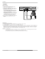
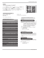
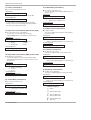
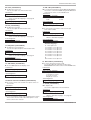
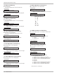
PLASMA MONITOR
OWNER’S MANUAL
MODELS : MU-60PZ95V
Please read this owner’s manual thoroughly before operating
the Monitor.
Retain it for future reference.
Record model number and serial number of the Monitor.
See the label attached on the back of the Monitor and relate
this information to your dealer if you ever require service.
Model Number :
Serial Number :
LG Electronics U.S.A., Inc.
Warning
Warning
WARNING/CAUTION
RISK OF ELECTRIC SHOCK
DO NOT OPEN
WARNING/CAUTION:
TO REDUCE THE RISK OF ELECTRIC SHOCK DO NOT REMOVE COVER (OR BACK). NO USER
SERVICEABLE PARTS INSIDE. REFER TO QUALIFIED SERVICE PERSONNEL.
The lightning flash with arrowhead symbol, within an equilateral triangle, is intended to alert the user to
the presence of uninsulated “dangerous voltage” within the product’s enclosure that may be of sufficient magnitude to constitute a risk of electric shock to persons.
The exclamation point within an equilateral triangle is intended to alert the user to the presence of
important operating and maintenance (servicing) instructions in the literature accompanying the appliance.
WARNING/CAUTION:
TO PREVENT FIRE OR SHOCK HAZARDS, DO NOT EXPOSE THIS PRODUCT TO RAIN OR MOISTURE.
FCC NOTICE
• A Class B digital device
This equipment has been tested and found to comply with the limits for a Class B digital device, pursuant to Part
15 of the FCC Rules. These limits are designed to provide reasonable protection against harmful interference in
a residential installation. This equipment generates, uses and can radiate radio frequency energy and, if not
installed and used in accordance with the instructions, may cause harmful interference to radio communications.
However, there is no guarantee that interference will not occur in a particular installation. If this equipment does
cause harmful interference to radio or television reception, which can be determined by turning the equipment off
and on, the user is encouraged to try to correct the interference by one or more of the following measures:
- Reorient or relocate the receiving antenna.
- Increase the separation between the equipment and receiver.
- Connect the equipment into an outlet on a circuit different from that to which the receiver is connected.
- Consult the dealer or an experienced radio/TV technician for help.
• Any changes or modifications not expressly approved by the party responsible for compliance could void the user’s authority to operate the equipment.
CAUTION:
Do not attempt to modify this product in any way without written authorization from LG Electronics. Unauthorized modification could void the user’s authority to operate this product.
COMPLIANCE:
The responsible party for this product’s compliance is:
LG Electronics U.S.A., Inc
1000 Sylvan Avenue, Englewood Cliffs, NJ 07632
1-800-243-0000
http://www.lgusa.com
WARNING/CAUTION
TO REDUCE THE RISK OF FIRE AND ELECTRIC SHOCK, DO NOT EXPOSE THIS PRODUCT TO
RAIN OR MOISTURE.
2 Plasma Monitor
Warning
Safety Instructions
Important safeguards for you and your new product
Your product has been manufactured and tested with your safety in mind. However, improper use can result in potential electrical shock or fire hazards. To avoid defeating the safeguards that have been built into your new product, please read and
observe the following safety points when installing and using your new product, and save them for future reference.
Observing the simple precautions discussed in this booklet can help you get many years of enjoyment and safe operation
that are built into your new product.
This product complies with all applicable U.S. Federal safety requirements, and those of the Canadian Standards
Association.
1. Read these instructions.
2. Keep these instructions.
3. Heed all warnings.
4. Follow all instructions.
5. Do not use this apparatus near water.
6. Clean only with dry cloth.
7. Do not block any ventilation openings. Install in accordance with the manufacturer’s instructions.
8. Do not install near any heat sources such as radiators, heat registers, stoves, or other apparatus (including amplifiers)that produce heat.
9. Do not defeat the safety purpose of the polarized or grounding-type plug. A polarized plug has two blades with
one wider than the other. A grounding type plug has two blades and a third grounding prong, The wide blade or the
third prong are provided for your safety. If the provided plug does not fit into your outlet, consult an electrician for
replacement of the obsolete outlet.
10. Protect the power cord from being walked on or pinched particularly at plugs, convenience receptacles, and the
point where they exit from the apparatus.
Owner’s Manual 3
Safety Instructions
Safety Instructions continued
11. Only use attachments/accessories specified by the manufacturer.
12. Use only with the cart, stand, tripod, bracket, or table specified by the manufacturer, or sold with the apparatus.
When a cart is used, use caution when moving the cart/apparatus combination to avoid injury from tip-over.
PORTABLE CART WARNING
13. Unplug this apparatus during lightning storms or when unused for long periods of time.
14. Refer all servicing to qualified service personnel. Servicing is required when the apparatus has been damaged
in any way, such as power-supply cord or plug is damaged, liquid has been spilled or objects have fallen into the
apparatus, the apparatus has exposed to rain or moisture, does not operate normally, or has been dropped.
15. Outdoor Use Marking :
WARNING - To Reduce The Risk Of Fire Or Electric Shock, Do Not Expose This Appliance To Rain Or Moisture.
16. Wet Location Marking :
Apparatus shall not be exposed to dripping or splashing and no objects filled with liquids, such as vases, shall
be placed on the apparatus.
4 Plasma Monitor
Safety Instructions
Contents
Warning/Caution . . . . . . . . . . . . . . . . . . . . . . . . . . . . . . . .2
Safety Instructions . . . . . . . . . . . . . . . . . . . . . . . . . . . . .3~4
Introduction
Controls and Connection Options . . . . . . . . . . . .7
Remote Control Key Functions . . . . . . . . . . . . . .8
Installation
Installation Instructions . . . . . . . . . . . . . . . . . . .9~10
External Equipment Connections . . . . . . . . . .11~15
VCR Setup . . . . . . . . . . . . . . . . . . . . . . . . . . . .11
Cable TV Setup . . . . . . . . . . . . . . . . . . . . . . . .11
External A/V Source Setup . . . . . . . . . . . . . . . .12
DVD Setup . . . . . . . . . . . . . . . . . . . . . . . . . . . .12
DTV Setup / Monitor Out Setup . . . . . . . . . . . . .13
PC Setup . . . . . . . . . . . . . . . . . . . . . . . . . .14~15
Operation
Turning on the Monitor . . . . . . . . . . . . . . . . . . . . .16
Menu Language Selection . . . . . . . . . . . . . . . . . .16
Picture Menu Options
APC (Auto Picture Control) . . . . . . . . . . . . . . . .17
XD . . . . . . . . . . . . . . . . . . . . . . . . . . . . . . . . . .17
Color Temperature Control . . . . . . . . . . . . . . . .17
Fleshtone . . . . . . . . . . . . . . . . . . . . . . . . . . . . .18
sRGB . . . . . . . . . . . . . . . . . . . . . . . . . . . . . . . .18
Manual Picture Control(APC set to Off option) . . .18
Sound Menu Options
DASP (Digital Auto Sound Processing) . . . . . . .19
BBE . . . . . . . . . . . . . . . . . . . . . . . . . . . . . . . . .19
AVL (Auto Volume Leveler) . . . . . . . . . . . . . . . .19
Manual Sound Control(DASP set to Off option) . .20
Timer Menu Options
Clock Setup . . . . . . . . . . . . . . . . . . . . . . . . . . .21
On/Off Timer Setup . . . . . . . . . . . . . . . . . . . . .21
Auto Off / Sleep Timer . . . . . . . . . . . . . . . . . . .21
Special Menu Options
Key Lock . . . . . . . . . . . . . . . . . . . . . . . . . . . . .22
ISM (Image Sticking Minimization) Method . . . .22
Low Power . . . . . . . . . . . . . . . . . . . . . . . . . . . .23
XD Demo . . . . . . . . . . . . . . . . . . . . . . . . . . . . .23
Menu Rotation for Vertical Viewing . . . . . . . . . . .23
Screen Menu Options
Auto Adjustment . . . . . . . . . . . . . . . . . . . . . . .24
Setting Picture Format . . . . . . . . . . . . . . . . . . .24
Screen Position . . . . . . . . . . . . . . . . . . . . . . . .24
Manual Configure . . . . . . . . . . . . . . . . . . . . . .25
Selecting VGA/XGA Mode . . . . . . . . . . . . . . . .25
Screen Adjustments . . . . . . . . . . . . . . . . . . . . .25
Cinema Mode Setup . . . . . . . . . . . . . . . . . . . . .25
Luminance Noise Reduction . . . . . . . . . . . . . . .26
Initializing (Reset to original factory value) . . . . .26
Split Zoom . . . . . . . . . . . . . . . . . . . . . . . . . . . .26
PIP (Picture-In-Picture)/Double Window Feature
Watching PIP/Double Window . . . . . . . . . . . . ..27
Swapping the PIP/Double Window . . . . . . . . . .27
Selecting an Input Signal Source for PIP/Double Window .27
Moving the PIP(PIP Mode only) . . . . . . . . . . . .27
PIP Size . . . . . . . . . . . . . . . . . . . . . . . . . . . . . .27
PIP Transparency (PIP Mode only) . . . . . . . . . .27
External Control Device Setup . . . . . . . . . . . . . . . .28~33
IR Code Information
. . . . . . . . . . . . . . . . . . . . . . .34~35
Troubleshooting Checklist . . . . . . . . . . . . . . . . . . . . . .36
Maintenance . . . . . . . . . . . . . . . . . . . . . . . . . . . . . . . . .37
Specifications . . . . . . . . . . . . . . . . . . . . . . . . . . . . . . . .38
Warranty . . . . . . . . . . . . . . . . . . . . . . . . . . . . . . . . .39~40
Owner’s Manual 5
Introduction
Introduction
What is a Plasma Display Panel (PDP)?
If voltage is applied to gas within glass panels, ultraviolet rays are produced and fused with a fluorescent substance. At that
instant, light is emitted. A Plasma Display is a next generation flat Display using this phenomenon.
160° - Wide angle range of vision
Your flat panel plasma screen offers an exceptionally broad viewing angle -- over 160 degrees. This means that the display is
clear and visible to viewers who can see the screen anywhere in the room.
Wide Screen
The screen of the Plasma Display is 60" so wide that your viewing experience is as if you are in a theater.
Multimedia
Connect your plasma display to a PC and you can use it for conferencing, games, and internet browsing. The Picture-in-Picture
feature allows you to view your PC and video images simultaneously.
Versatile
The light weight and thin size makes it easy to install your plasma display in a variety of locations where conventional TVs would
not fit.
The PDP Manufacturing Process: Why minute colored dots may be present on the PDP screen
The PDP (Plasma Display Panel) which is the display device of this product is composed of 0.9 to 2.2 million cells. A few cell
defects will normally occur in the PDP manufacturing process. Several minute colored dots visible on the screen should be acceptable. This also occurs in other PDP manufacturers' products and the tiny dots appearing does not mean that this PDP is defective.
Thus a few cell defects are not sufficient cause for the PDP to be exchanged or returned. Our production technology is designed
to minimize cell defects during the manufacture and operation of this product.
Cooling Fan Noise
In the same way that a fan is used in a PC computer to keep the CPU (Central Processing Unit) cool, the PDP is equipped with
cooling fans to cool the Monitor and improve its reliability. Therefore, a certain level of noise could occur while the fans are operating and cooling the PDP.
The fan noise doesn't have any negative effect on the PDP's efficiency or reliability. The noise from these fans is normal during the
operation of this product. We hope you understand that a certain level of noise from the cooling fans is acceptable and is not sufficient cause for the PDP to be exchanged or returned.
6 Plasma Monitor
Introduction
Controls
Front Panel Controls
- This is a simplified representation of a typical front panel.
The Front Panel Controls shown here may be somewhat different from your monitor.
INPUT
SELECT VOLUME
ON/OFF
Main Power Button
INPUT SELECT Button
Sub Power Button
VOLUME (F,G) Buttons
Power Standby Indicator
Illuminates red in standby
mode. Illuminates green when
the Monitor is turned on.
Remote Control Sensor
Connection Options
Back Connection Panel
Y
REMOTE
RS-232C INPUT
CONTROL
(CONTROL/SERVICE)
1
2
PB
PR
R
L
R
L/MONO
COMPONENT INPUT 1
DVI INPUT
AUDIO INPUT
RGB INPUT
A/V INPUT
3
EXTERNAL SPEAKER
RGB OUTPUT
VIDEO
4
1. REMOTE CONTROL
Connect your wired remote control to the remote control
port on the Monitor.
2. RS-232C INPUT (CONTROL/SERVICE) PORT
Connect to the RS-232C port on a PC.
3. DVI (Digital Visual Interface) INPUT/
AUDIO INPUT/ RGB INPUT JACKS
Connect the monitor output connector from a PC to the
appropriate input port.
4. RGB OUTPUT PORT
You can watch the RGB signal on another monitor, connect
RGB OUTPUT to another monitor’s PC input port.
5. DVD/DTV Input (Component 1-2)
Connect a component video/audio device to these jacks.
5
AUDIO
AUDIO
VIDEO
6
( )L( )
( )R( )
MONITOR
OUTPUT
COMPONENT INPUT 2
AC INPUT
S-VIDEO
7
8
9
6. Monitor Output
Connect a second Monitor.
Audio/Video Input
Connect audio/video output from an external device to
these jacks.
7. S-Video Input
Connect S-Video out from an S-VIDEO device to the SVIDEO input.
8. EXTERNAL SPEAKER (8 ohm output)
Connect to optional external speaker(s).
* For further information, refer to ‘Speaker & Speaker
Stand’ manual.
9. POWER CORD SOCKET
This Monitor operates on an AC power. The voltage is indicated on the Specifications page. Never attempt to operate
the Monitor on DC power.
Owner’s Manual 7
Introduction
Remote Control Key Functions
- When using the remote control, aim it at the remote control sensor on the monitor.
- Under certain conditions such as if the remote IR signal is interrupted, the remote control may not function. Press
the key again as necessary.
POWER
Switches the Monitor between
ON and STANDBY.
SLEEP
Sets the Sleep Timer.
(Refer to p.21)
INPUT SELECT
Selects source: RGB, DVI,
Component, Video or SVideo,mode.
POWER
SLEEP
APC
Adjusts the factory preset picture
according to the room.
(Refer to p.17)
APC
DASP
ARC
SPLIT ZOOM
WIN.POSITION
PIP/DW
ARC
Changes the picture format.
(Refer to p.24)
PIP/DW
Switches the sub picture on or off.
(Refer to p.27)
DASP
To select the sound appropriate to
your viewing program character:
SRS TSXT, Flat, Music, Movie,
Sports, or Off (Refer to p.19)
INPUT SELECT
SWAP
SPLIT ZOOM
Enlarges the picture.
SUB INPUT
MENU
MUTE
WIN.POSITION
Moves the sub picture.
OK
VOL
VOL
SUB INPUT
Selects the input source for the sub
picture.
SWAP
Exchanges main and sub picture
images. (Refer to p.27)
MENU
Displays on screen menus one by one.
Exits the current menu.
MUTE
Switches the sound on or off.
1
2
3
4
5
6
7
8
9
0
WIN.SIZE
NUMBER buttons
POWER
STOP
PAUSE
REW
PLAY
FF
DVD
Control some DVD cassette
recorders.
SKIP
OK
D /E
Selects menu option.
Memorizes menu changes.
F / G (Volume button)
Increases/decreases sound level.
Adjusts menu settings.
OPEN/CLOSE
DVD
POWER
W
VCR
STOP
P/STILL
REC
PLAY
FF
WIN.P
REW
WIN.SIZE
Adjusts the sub picture size.
VCR BUTTONS
Control some video cassette
recorders.
Installing Batteries
• Open the battery compartment cover on the back side and
insert the batteries with correct polarity.
• Install two 1.5V alkaline batteries of AAA type. Don’t mix used
batteries with new batteries.
8
Plasma Monitor
Introduction
Installation
Ensure that the following accessories are included with your plasma display. If an accessory is missing, please contact the dealer
where you purchased the product.
POWER
SLEEP
INPUT SELECT
APC
DASP
ARC
PIP ARC
PIP
TWIN PICTURE
SUB INPUT
SWAP
MENU
1.5V
1.5V
MUTE
VOL
OK
1
2
4
5
7
8
VOL
3
6
9
0
Owner’s Manual
Alkaline Batteries
POWER
STOP
P/STILL
REW
PLAY
FF
REC
WIN.SIZE WIN.POSITION SPLIT ZOOM
ZOOM -
ZOOM +
Remote Control
DVI-D Cable
D-sub 15 pin Cable
Power Cord
Installation Instructions
• The Monitor can be installed in various ways such as on a wall, or on a desktop etc.
• The plasma display is designed to be mounted horizontally or vertically. The speakers shown are optional.
GROUNDING
Power
Supply
Ensure that you connect the grounding / earth wire to prevent possible
electric shock. If grounding methods are not possible, have a qualified
electrician install a separate circuit breaker. Do not try to ground the
unit by connecting it to telephone wires, lightening rods, or gas pipes.
yyyyyy
;;;;;;
;;;;;;
yyyyyy
;;;;;;
yyyyyy
;;;;;;
yyyyyy
;;;;;;
yyyyyy
Short-circuit
Breaker
Wall Mount Installation
For proper ventilation, allow a clearance of 4” on each
side and 2” from the wall. Detailed installation instructions are available from your dealer, see the optional
Wall Mounting Bracket Installation and Setup Guide.
2 inches
4 inches
4 inches
4 inches
4 inches
Owner’s Manual 9
Installation
Installation Instructions continued
Desktop Pedestal Installation
For proper ventilation, allow a clearance of 4” on each
side and the top, 2.36” on the bottom, and 2” from the
wall. Detailed installation instructions are included in the
optional Desktop Stand Installation and Setup Guide
available from your dealer.
4 inches
4 inches
2 inches
4 inches
2.36 inches
;;;;;;;
;;;;;;;
;;;;;;;
;;;;;;;
;;;;;;;
Wall Mount: Vertical
Vertical installation
Detailed installation instructions are included in the
optional Vertical Wall Mounting Bracket Installation and
Setup Guide available from your dealer.
NOTE: When installing the monitor vertically, the front
panel controls must be in the left side position.
10
Plasma Monitor
When installing the monitor vertically, you
have to change the OSD display mode so
that the menus will appear correctly and also
to protect the monitor from overheating.
Installation
External Equipment Connections
NOTE: All cables shown are not included with the Monitor
VCR Setup
- To avoid picture noise (interference), leave an adequate distance between the VCR and Monitor
- Use the ISM Method (on the Option menu) feature to avoid having a fixed image remain on the screen for a long period of time.
Typically a frozen still picture from a VCR. If the 4:3 picture format is used; the fixed images on the sides of the screen may
remain visible on the screen.
Connection Option 1
Set VCR output switch to 3 or 4 and then tune
Monitor to the same channel number.
Connection Option 2
1. Connect the audio and video cables from the
VCR's output jacks to the Monitor input jacks,
as shown in the figure.
When connecting the Monitor to VCR, match
the jack colors (Video = yellow, Audio Left =
white, and Audio Right = red).
If you connect an S-VIDEO output from VCR to
the S-VIDEO input, the picture quality is
improved; compared to connecting a regular
VCR to the Video input.
2. Insert a video tape into the VCR and press
PLAY on the VCR. (Refer to the VCR owner’s
manual.)
3. Select the input source with using the INPUT
SELECT button on the remote control. (If connected to A/V INPUT 1, select Video input
source)
RGB INPUT
Y
PB
PR
R
R
L
L/MONO
COMPONENT INPUT 1
A/V INPUT
VIDEO
S-VIDEO
( )R( )
MONITOR
OUTPUT
COMPONENT INPUT 2
RGB OUTPUT
AUDIO
AUDIO
( )L( )
EXTERNAL SPEAKER
AC INPUT
S-VIDEO
VIDEO
VCR
OUT
(R) AUDIO (L)
VIDEO
IN
Do not connect to both Video and SVideo at the same time. In the event
that you connect both Video and the
S-Video cables, only the S-Video will
work.)
Cable TV Setup
- After subscribing to a cable TV service from a local provider and installing a converter, you can watch cable TV programming.
The TV cannot display TV programming unless a TV tuner device or cable TV converter box is connected to the TV.
- For further information regarding cable TV service, contact your local cable TV service provider(s).
Connection Option 1
1. Select 3 or 4 with channel switch on cable box.
2. Tune the TV channel to the same selected output channel on
cable box.
3. Select channels at the cable box or with the cable box remote
control.
Y
PB
PR
R
R
L
L/MONO
COMPONENT INPUT 1
A/V INPUT
VIDEO
Connection Option 2
1. Connect the audio and video cables from the Cable Box's
output jacks to the TV input jacks, as shown in the figure.
When connecting the TV to a Cable Box, match the jack colors (Video = yellow, Audio Left = white, and Audio Right =
red).
2. Select the input source with using the INPUT SELECT button
on the remote control. (If connected to A/V INPUT 1, select
Video input source)
3. Select your desired channel with the remote control for cable
box.
( )R( )
MONITOR
OUTPUT
COMPONENT INPUT 2
TPUT
AUDIO
AUDIO
VIDEO
(R) AUDIO (L)
( )L( )
EXTERNAL SPEAKER
S-VIDEO
AC INPUT
VIDEO
TV
VCR
RF
Cable
Cable Box
Owner’s Manual 11
Installation
External A/V Source Setup
How to connect
Connect the audio and video cables from the external
equipment's output jacks to the Monitor input jacks, as
shown in the figure.
When connecting the Monitor to external equipment, match
the jack colors (Video = yellow, Audio Left = white, and
Audio Right = red).
Y
PB
PR
R
R
L
( )R( )
MONITOR
OUTPUT
COMPONENT INPUT 2
L/MONO
COMPONENT INPUT 1
A/V INPUT
VIDEO
AC INPUT
S-VIDEO
VIDEO
AUDIO
AUDIO
( )L( )
EXTERNAL SPEAKER
UT
How to use
1. Select the input source with using the INPUT SELECT button on the remote control. (If connected to A/V INPUT 1,
select Video input source).
2. Operate the corresponding external equipment. Refer to
external equipment operating guide.
Camcorder
R
AUDIO
VIDEO
L
Video Game Set
DVD Setup
How to connect
1. Connect the DVD video outputs (Y, PB, PR) to the COMPONENT (Y, PB, PR) INPUT jacks on the Monitor and connect the
DVD audio outputs to the AUDIO INPUT jacks on the Monitor,
as shown in the figure.
2. If your DVD only has an S-Video output jack, connect this to the
S-VIDEO input on the Monitor and connect the DVD audio outputs to the AUDIO INPUT jacks on the Monitor, as shown in the
figure.
NOTE: If your DVD player does not have component video output,
use S-Video.
Y
PB
PR
R
L
R
( )R( )
MONITOR
OUTPUT
COMPONENT INPUT 2
L/MONO
COMPONENT INPUT 1
VIDEO
AUDIO
AUDIO
VIDEO
S-VIDEO
How to use
1. Turn on the DVD player, insert a DVD.
2. Use the INPUT SELECT button on the remote control to select
Component 1 or Component 2. (If connected to S-VIDEO,
select the Video external input source.)
3. Refer to the DVD player's manual for operating instructions.
• Component Input ports
To get better picture quality, connect a DVD player to the component input ports as shown below.
12
Component ports
on the Monitor
Y
PB
Video output ports
on DVD player
Y
Y
Y
Y
Pr
Pb
B-Y R-Y
Cb Cr
PB PR
Plasma Monitor
PR
( )L( )
EXTERNAL SPEAKER
UT
or
B
R
(R) AUDIO (L)
S-VIDEO
DVD
(R) AUDIO (L)
AC INPUT
Installation
DTV Setup
- To watch digitally broadcast programs, purchase and connect a digital set-top box.
Y
RS-232C INPUT
CONTROL
(CONTROL/SERVICE)
PB
PR
R
L
R
L/MONO
COMPONENT INPUT 1
DVI INPUT
AUDIO INPUT
RGB INPUT
A/V INPUT
RGB OUTPUT
VIDEO
or
DVI-DTV OUTPUT (R) AUDIO (L)
( )R( )
MONITOR
OUTPUT
COMPONENT INPUT 2
REMOTE
AUDIO
S-VIDEO
VIDEO
AUDIO
( )L(
EXTERNAL SPEAKER
or
(R) AUDIO (L) RGB-DTV OUTPUT
B
R
(R) AUDIO (L)
Digital Set-top Box
How to connect
Use the Monitor’s COMPONENT (Y, PB, PR) INPUT, RGB or DVI jack for
video connections, depending on your set-top box connector. Then, make
the corresponding audio connections.
How to use
1. Turn on the digital set-top box. (Refer to the owner’s manual for the digital
set-top box.)
2. Use INPUT SELECT on the remote control to select Component 1,
Component 2, RGB, or DVI source.
Signal
480i
480p
720p
1080i
Component 1/2
Yes
Yes
Yes
Yes
RGB,DVI
No
Yes
Yes
Yes
Monitor Out Setup
The Monitor has a special signal output capability which allows you
to hook up a second monitor.
Y
PB
PR
R
R
L
( )R( )
MONITOR
OUTPUT
COMPONENT INPUT 2
L/MONO
COMPONENT INPUT 1
A/V INPUT
GB OUTPUT
VIDEO
AUDIO
AUDIO
AUDIO
VIDEO
VIDEO
( )L( )
EXTERNAL SPEAKER
S-VIDEO
Connect the second monitor to the Monitor’s MONITOR OUTPUT.
See the Operating Manual of the second Monitor or monitor for further details regarding that device’s input settings.
NOTE
• Component, RGB-PC/RGB-DTV, DVI-PC/DVI-DTV input sources
cannot be used for Monitor out.
S-VIDEO
IN
(R) AUDIO (L)
VIDEO
Owner’s Manual 13
Installation
PC Setup
How to connect
1. To get the best picture quality, adjust the PC
graphics card to 1024x768, 75Hz.
2. Use the Monitor’s RGB INPUT or DVI (Digital
Visual Interface) INPUT port for video connections,
depending on your PC connector.
• If the graphic card on the PC does not output
analog and digital RGB simultaneously, connect
only one of either RGB INPUT or DVI INPUT to
display the PC on the Monitor.
• If the graphic card on the PC does output analog
and digital RGB simultaneously, set the Monitor
to either RGB or DVI; (the other mode is set to
Plug and Play automatically by the Monitor.)
3. Then, make the corresponding audio connection. If
using a sound card, adjust the PC sound as
required.
COMPONENT INPUT 2
Y
REMOTE
RS-232C INPUT
CONTROL
(CONTROL/SERVICE)
PB
PR
R
L
(R)
(L/MONO)
COMPONENT INPUT 1
DVI INPUT
AUDIO INPUT
RGB INPUT
RGB OUTPUT
VIDEO
AUDIO
How to use
1. Turn on the PC and the Monitor.
2. Turn on the display by pressing the POWER button on the Monitor's remote control.
3. Use INPUT SELECT on the remote control to select RGB, or DVI source.
4. Check the image on your Monitor. There may be noise associated with the resolution, vertical pattern, contrast or brightness in
PC mode. If noise is present, change the PC mode to another resolution, change the refresh rate to another rate or adjust the
brightness and contrast on the menu until the picture is clear. If the refresh rate of the PC graphic card can not be changed,
change the PC graphic card or consult the manufacturer of the PC graphic card.
NOTES: • Use a DVI cable.
• Avoid keeping a fixed image on the Monitor's screen for a long period of time. The fixed image may become permanently imprinted on the screen. Use the Orbiter screen saver when possible.
• The synchronization input form for Horizontal and Vertical frequencies is separate.
14
Plasma Monitor
Installation
Monitor Display Specifications
•
RGB Input (PC )
Resolution
640x350
720x400
640x480
800x600
832x624
848x480
Vertical
Horizontal
Frequency(KHz) Frequency(Hz)
31.468
70.09
Resolution
31.500
60.00
37.799
70.00
70.08
39.375
75.00
37.927
85.03
48.363
60.00
31.469
59.94
56.476
70.06
35.000
66.66
60.023
75.02
37.861
72.80
68.677
85.00
37.500
75.00
54.348
60.05
43.269
85.00
63.995
70.01
35.156
56.25
67.500
75.00
37.879
60.31
77.487
85.00
48.077
72.18
68.681
75.06
46.875
75.00
47.693
59.99
53.674
85.06
60.091
74.93
49.725
74.55
68.504
84.88
31.500
60.00
1280x960
60.023
60.02
37.799
70.00
1280x1024
63.981
60.02
39.375
75.00
47.700
60.00
59.625
75.02
47.700
60.00
59.625
75.02
37.861
85.08
31.469
852x480
1024x768
1152x864
1152x870
1280x768
1360x768
1366x768
•
Horizontal
Vertical
Frequency(KHz) Frequency(Hz)
DVI Input PC (DVI-D )
Resolution
640x350
720x400
640x480
800x600
832x624
848x480
Horizontal
Vertical
Frequency(KHz) Frequency(Hz)
31.468
70.09
Resolution
Horizontal
Vertical
Frequency(KHz) Frequency(Hz)
31.500
60.00
37.799
70.00
39.375
75.00
48.363
60.00
56.476
70.06
66.66
60.023
75.02
72.80
47.693
59.99
60.091
74.93
68.504
84.88
37.861
85.08
31.469
70.08
37.927
85.03
31.469
59.94
35.000
37.861
852x480
1024x768
1280x768
37.500
75.00
43.269
85.00
37.879
60.31
1280x960
60.023
60.02
48.077
72.18
1280x1024
63.981
60.02
46.875
75.00
1360x768
47.700
60.00
53.674
85.06
59.625
75.02
49.725
74.55
47.700
60.00
31.500
60.00
59.625
75.02
37.799
70.00
39.375
75.00
1366x768
Owner’s Manual 15
Operation
Operation
Turning on the Monitor
Turning on the Monitor just after installation
1. Connect power cord correctly.
2. Press the
ON/OFF button on the Monitor. At this moment, the Monitor is switched to standby
mode. Press the INPUT SELECT button on the Monitor or press the POWER, INPUT SELECT
button on the remote control and then the Monitor will switch on.
Turning on the Monitor (power cord is still connected)
1. If the Monitor was turned off with the
• Press the
ON/OFF button on the Monitor
ON/OFF button on the Monitor to turn the Monitor on.
2. If the Monitor was turned off with the remote control and then the
ON/OFF button on the Monitor
• Press the
ON/OFF button on the Monitor and then press the INPUT SELECT button on the
Monitor or press the POWER, INPUT SELECT button on the remote control to turn the Monitor on.
Menu Language Selection
- The menus can be shown on the screen in the selected language. First select your language.
1. Press the MENU button and then use
2. Press the G button and then use D /
E
D
/
E
button to select the SPECIAL menu.
button to select Language.
3. Press the G button and then use D / E button to select your desired language.
From this point on, the on-screen menus will be shown in the language of your
choice.
4. Press the OK button to save.
16 Plasma Monitor
Operation
Picture Menu Options
APC (Auto Picture Control)
- APC adjusts the Monitor to the best picture appearance.
- If adjusting picture options (contrast, brightness, color, sharpness, or tint) manually, APC automatically
changes to Off.
1. Press the APC button repeatedly to select the picture appearance setup option as shown below.
Daylight
Optimum
Night time
Off
• You can also adjust APC in the PICTURE menu.
• Daylight, Optimum and Night time settings are preset for good picture quality at the factory and cannot be
changed.
XD
- XD is LG Electronic’s unique picture improving technology to display a real HD
source through an advanced digital signal processing algorithm.
- When selecting APC options (Clear, Optimum and Soft), XD is automatically
change to On.
PICTURE
APC
G
ACC
Off
Fleshtone
1. Press the MENU button and then use D
/E
2. Press the G button and then use
D /E
button to select XD.
Brightness 55
D /E
button to set On or Off.
Sharpness 60
3. Press the
G
button and then use
button to select the PICTURE menu.
4. Press the OK button to save.
On
Contrast
100
Color
55
Tint
0
Menu
Prev.
Color Temperature Control
Auto Color Temperature Control
PICTURE
- To initialize values (reset to default settings), select the Normal option.
APC
Cool
1. Press the MENU button and then use D
2. Press the
G
button and then use
D /E
/E
button to select the PICTURE menu.
button to select ACC .
3. Press the G button and then use D / E button to select either: Cool (Preset),
Normal (Default), or Warm (Preset).
4. Press the OK button to save.
G
ACC
Fleshtone
Contrast
Warm
100
Brightness 55
Color
55
Sharpness 60
Tint
Menu
Normal
0
Off
Red
0
Green
0
Blue
0
Prev.
Manual Color Temperature Control (ACC set to Off option)
- You can adjust red, green, or blue to any color temperature you prefer.
1. Press the MENU button and then use D
/E
button to select the PICTURE menu.
2. Press the
G
button and then use
3. Press the
G
button and then use D
/E
button to select Off.
4. Press the
G
button and then use D
/E
button to select Red, Green or Blue.
5. Use the
F /G
D /E
button to select ACC .
button to make appropriate adjustments.
• The adjustment range of Red, Green, and Blue is -30 ~ +30.
6. Press the OK button to save.
Owner’s Manual 17
Operation
Fleshtone ( RGB-DTV,
RGB-DTV, and DVI-DTV Mode only)
- Use Fleshtone to select the desired skin color option.
PICTURE
APC
1. Press the MENU button and then use D
/E
2. Press the G button and then use
button to select Fleshtone.
button to select the PICTURE menu.
ACC
D /E
3. Press the G button and then use F
/G
button to make appropriate adjustments.
G
Fleshtone
Contrast
Brightness 55
Color
• The adjustment range is 0 ~ 3.
0
100
55
Sharpness 60
4. Press the OK button to save.
Tint
0
Menu
Prev.
sRGB (only RGB-PC, DVI-PC Modes)
- If the Monitor is connected to external equipment using sRGB, set sRGB to On
to adjust for the color difference.
APC
1. Press the MENU button and then use D
/E
ACC
2. Press the G button and then use
button to select sRGB.
button to select the PICTURE menu.
PICTURE
G
On
100
Off
sRGB
3. Press the
G
button and then use
D /E
D /E
button to select On or Off.
Contrast
Brightness 55
Color
55
Sharpness 60
4. Press the OK button to save.
Menu
Prev.
Manual Picture Control ( APC set to Off option)
- You can adjust picture contrast, brightness, color, sharpness, and tint options
to the levels you prefer.
PICTURE
APC
1. Press the MENU button and then use D
/E
button to select the PICTURE menu.
ACC
2. Press the G button and then use D / E button to select the desired picture option
(Contrast, Brightness, Color, Sharpness, Tint).
Fleshtone
3. Press the G button and then use F
Color
4. Press the OK button to save.
/G
button to make appropriate adjustments.
Contrast
Plasma Monitor
55
Sharpness 60
Tint
Menu
18
100
Brightness 55
0
Prev.
G
Operation
Sound Menu Options
DASP (Digital Auto Sound Processing)
- This function lets you enjoy the best sound without any special adjustment because the Monitor has the appropriate sound options based on the program content.
- If you adjust sound options (Treble and Bass) manually, DASP automatically changes to Off.
1. Press the DASP button repeatedly to select the appropriate sound setup as shown below.
SRS TSXT
Flat
Music
Movie
Sports
Off
• You can also adjust DASP in the SOUND menu.
• SRS TSXT, Flat, Music, Movie, and Sports are preset for good sound quality at the factory and cannot be changed.
•
is a trademark of SRS Labs, Inc.
• TruSurround XT technology is incorporated under license from SRS Labs, Inc.
BBE
- BBE High Definition Sound restores clarity and presence for better speech
intelligibility and music realism.
SOUND
DASP
1. Press the MENU button and then use
D /E
button to select the SOUND menu.
2. Press the
G
button and then use
D /E
button to select BBE.
3. Press the
G
button and then use
D /E
button to select On or Off.
4. Press the OK button to save.
G
BBE
Balance
0
Treble
50
Bass
50
Menu
•
On
Off
AVL
Prev.
Manufactured under license from BBE Sound, Inc.
• Treble, Bass and BBE aren’t suitable for SRS TSXT mode.
AVL (Auto Volume
Volume Leveler)
- AVL maintains an equal sound level; even if you change channels.
1. Press the MENU button and then use
2. Press the
3. Press the
G
G
button and then use
button and then use
4. Press the OK button to save.
D /E
D /E
D /E
button to select the SOUND menu.
button to select AVL.
button to select On or Off.
SOUND
DASP
BBE
AVL
G
On
Balance
0
Off
Treble
50
Bass
50
Menu
Prev.
Owner’s Manual 19
Operation
Manual Sound Control ( DASP set to Off option)
- You can adjust sound options Balance, Treble, and Bass to the levels you prefer.
SOUND
DASP
BBE
AVL
1. Press the MENU button and then use D
/E
button to select the SOUND menu.
2. Press the G button and then use D
(Balance, Treble, Bass).
/E
button to select the desired sound option
3. Press the G button and then use F
/G
button to make appropriate adjustments.
4. Press the OK button to save.
20
Plasma Monitor
Balance
0G
Treble
50
Bass
50
Menu
Prev.
L
R
Operation
T imer Menu Options
Clock Setup
- If current time setting is wrong, reset the clock manually.
TIMER
G
Clock
1. Press the MENU button and then use
D /E
2. Press the
G
button and then use
D /E
button to select Clock.
3. Press the
G
button and then use
D /E
button to set the hour.
4. Press the
G
button and then use
D /E
button to set the minutes.
-- :
--
AM
Off timer
button to select the TIMER menu.
On timer
Auto off
5. Press the OK button to save.
Prev.
Menu
On/Off
On/Off Timer Setup
-
Timer function operates only if current time has been set.
Off-Timer function overrides On-Timer function if they are set both set to the same time.
The Monitor must be in standby mode for the On-Timer to work.
If you do not press any button within 2 hours after the Monitor turns on with the On Timer function, the Monitor will automatically
revert to standby mode.
1. Press the MENU button and then use
2. Press the
G
button and then use
D /E
D /E
button to select the TIMER menu.
TIMER
button to select Off timer or On timer.
Clock
Off timer
3. Press the G button and then use D / E button to select On.
• To cancel On/Off timer function, select Off.
4. Press the
G
5. Press the
G
button and then use
D /E
button to set the hour.
button and then use
D /E
button to set the minutes.
6. For On timer function only
Press the G button and then use D
/E
On timer
On
G
Off
Auto off
6
:
30 AM
Volume 17
button to set the volume level at turn-on.
Prev.
Menu
7. Press the OK button to save.
Auto Off
Off
- If set to on and there is no input signal, the Monitor turns off automatically after
10 minutes.
TIMER
Clock
1. Press the MENU button and then use D / E button to select the TIMER menu.
2. Press the G button and then use D / E button to select Auto off.
Off timer
On timer
Auto off
3. Press the G button and then use
D /E
button to select On or Off.
G
On
Off
4. Press the OK button to save.
Menu
Prev.
Sleep Timer
- The Sleep Timer turns the Monitor off at the preset time. Note that this setting is cleared when the monitor is turned off.
1. Press the SLEEP button repeatedly to select the number of preset minutes. First the
on the screen, followed by the following sleep timer turn off times:
10, 20, 30, 60, 90, 120, 180, and 240 minutes.
zz
--- Min option appears
2. When the number of minutes you want is displayed on the screen, press the OK button. The timer begins to count
down from the number of minutes selected.
3. To check the remaining minutes before the TV turns off, press the SLEEP button once.
4. To cancel the Sleep Timer, press the SLEEP button repeatedly until
zz
--- Min appears.
Owner’s Manual 21
Operation
Special Menu Options
Key Lock
- The Monitor can be set up so that it can only be used with the remote control.
- This feature can be used to prevent unauthorized viewing by locking out the front panel controls.
- This Monitor is programmed to remember which option it was last set to even if you turn the Monitor off.
1. Press the MENU button and then use D
/E
button to select the SPECIAL menu.
2. Press the
G
button and then use
D /E
button to select Key lock.
3. Press the
G
button and then use
D /E
button to select On or Off.
SPECIAL
Language
Key lock
G
On
Off
ISM Method
Low power
4. Press the OK button to save.
Set ID
• With the Key lock On, the display ‘ WKey lock’ appears on the screen if any
button on the front panel is pressed.
Demo
OSD Rotate
Menu
Prev.
ISM (Image Sticking Minimization) Method
- A frozen still picture from a PC/video game displayed on the screen for prolonged periods will result in a ghost image remaining
even when you change the image. Avoid allowing a fixed image to remain on the Monitor's screen for a long period of time.
1. Press the MENU button and then use D
2. Press the
G
button and then use
D /E
/E
button to select the SPECIAL menu.
button to select ISM Method.
SPECIAL
Language
3. Press the G button and then use
wash, Orbiter or Inversion.
D /E
button to select either Normal, White
• Normal
If image sticking is never a problem, ISM is not necessary - set to Normal.
• White wash
White Wash removes permanent images from the screen. Note: An excessive
permanent image may be impossible to clear entirely with White Wash. To
return to normal viewing, press any button.
• Orbiter
Orbiter may help prevent ghost images. However, it is best not to allow any
fixed image to remain on the screen. To avoid a permanent image on the
screen, the image will move every 2 minutes: Right → Right → Downside →
Downside → Left → Left → Upside → Upside.
• Inversion
Inversion will automatically invert the Monitor panel color every 30 minutes.
4. Press the OK button to save.
22
Plasma Monitor
Key lock
ISM Method
G
Normal
Low power
White wash
Set ID
Orbiter
Demo
OSD Rotate
Menu
Prev.
Inversion
Operation
Special Menu Options continued
Low Power
- Low power reduces the plasma display power consumption.
1. Press the MENU button and then use D
/E
button to select the SPECIAL menu.
2. Press the
G
button and then use
D /E
button to select Low power.
3. Press the
G
button and then use
D /E
button to select On or Off.
SPECIAL
Language
Key lock
ISM Method
Low power
• When you select On, the screen darkens.
G
Set ID
4. Press the OK button to save.
On
Off
Demo
OSD Rotate
Menu
Prev.
XD Demo
- Use it to see the difference between XD Demo on and XD Demo off.
SPECIAL
Language
1. Press the MENU button and then use D
/E
2. Press the
G
button and then use
3. Press the
G
button to begin XD Demo.
D /E
button to select the SPECIAL menu.
button to select
Demo.
Key lock
ISM Method
Low power
Set ID
Demo
4. Press the MENU button to stop XD Demo.
G
To start
G
Normal
OSD Rotate
Menu
Prev.
Menu Rotation for Vertical
Vertical Viewing
Viewing
1. Press the MENU button and then use
2. Press the G button and then use D
D /E
/E
button to select the SPECIAL menu.
button to select OSD (On Screen Display)
Rotate.
SPECIAL
Language
Key lock
ISM Method
3. Press the
G
button and then use
D /E
button to select Normal or Rotate.
• Select Normal, if the monitor was installed horizontally.
• Select Rotate, if the monitor was installed vertically.
Low power
Set ID
Demo
OSD Rotate
Rotate
4. Press the OK button to save.
Menu
Prev.
Owner’s Manual 23
Operation
Screen Menu Options
Auto Adjustment
-
RGB (PC) mode only; This function doesn’t work for RGB-DTV mode.
Automatically adjusts picture position and minimizes image shaking.
After adjustment, if the image is still not correct, your Monitor is functioning properly but needs further adjustment.
The Auto config., Position and Manual config. are not active in DVI mode.
1. Press the MENU button and then use D
2. Press the G button and then use
D /E
/E
button to select the SCREEN menu.
button to select Auto config..
SCREEN
G
Auto config.
To set
ARC
3. Press the G button to run Auto configure.
Position
• When Auto config. has finished, OK will be shown on screen.
• If the position of the image is still not correct, try Auto adjustment again.
Manual config
Reset
4. In RGB (PC) mode, if the image needs to be adjusted more after using Auto
config., you can make further adjustments with the Manual config. option.
Menu
Prev.
Setting Picture Format
-
Caution: If a 4:3 fixed image is on the screen for a long time, it may remain visible.
Set every aspect ratio for Monitor, Video, Component 480i sources.
Use 4:3, or 16:9 for other RGB-PC and DVI-PC sources.
Horizon is not available for Component (480p,720p,1080i), DTV (480p,720p,1080i) sources.
1. Press the ARC button repeatedly to select the desired picture format. You can also adjust ARC in the SCREEN menu.
• 4:3
Choose 4:3 when you want to view a picture with an original 4:3 aspect ratio, with black bars appearing at both the
left and right sides.
• 16:9
Choose 16:9 when you want to adjust the picture horizontally, in a linear proportion to fill the entire screen.
• Horizon
Choose Horizon when you want to adjust the picture in a non-linear proportion, that is, more enlarged at both sides,
to create a spectacular view.
• Zoom
- Choose Zoom when you want to view the picture without any alteration. However, the top and bottom portions of the
picture will be cropped.
Screen Position
- This function works in the following modes:
RGB-PC, RGB-DTV (480p,720p,1080i), DVI-DTV (480p,720p,1080i), COMPONENT (480p,720p,1080i).
1. Press the MENU button and then use D
/E
button to select the SCREEN menu.
2. Press the
G
button and then use
D /E
3. Press the
G
button and then use
D /E /F /G
button to select Position.
SCREEN
Auto config.
ARC
Position
Reset
button to adjust the position.
4. Press the OK button to save.
Menu
24
Plasma Monitor
G
Manual config
Prev.
F
D
E
G
Operation
Manual Configure (RGB-PC mode only)
1. Press the MENU button and then use D
/E
button to select the SCREEN menu.
2. Press the G button and then use
D /E
button to select Manual config..
3. Press the G button and then use
D /E
button to to select Phase or Clock.
4. Use the
F /G
button to make appropriate adjustments.
• The Phase adjustment range is 0 ~ 30.
• The Clock adjustment range is -127 ~ +128.
SCREEN
Auto config.
ARC
Position
Manual config
G
Reset
Phase
0
Clock
0
5. Press the OK button to save.
Menu
Selecting VGA/XGA Mode (RGB-PC mode only)
- To see a normal picture, match the resolution of RGB mode and selection of
VGA/XGA mode.
Prev.
SCREEN
Auto config.
ARC
Position
1. Press the MENU button and then use D
2. Press the
Mode).
G
button and then use
/E
D / E
button to select the SCREEN menu.
button to select VGA Mode (or XGA
Manual config
Reset
VGA Mode
G
640x480
848x480
852x480
3. Press the G button and then use D
olution.
/E
button to select the desired VGA/XGA resMenu
Prev.
4. Press the OK button to save.
Screen Adjustments (Video.S-V
ideo and Component 480i mode only)
(Video.S-Video
- Use this function to correct jittering or picture instability while viewing a video
tape.
SCREEN
Screen adj.
1. Press the MENU button and then use D
/E
button to select the SCREEN menu.
2. Press the G button and then use
D /E
button to select Screen adj..
3. Press the G button and then use
D /E
button to select TV or VCR.
G
TV
VCR
ARC
Cinema
YNR
Reset
• Select the VCR option if watching a VCR.
• Select the TV option for other equipment. (Except VCR)
4. Press the OK button to save.
Menu
Prev.
Cinema Mode Setup (Video,
(Video, S-Video
S-Video and Component 480i mode only)
- Sets up the Monitor for the best picture appearance for viewing movies.
1. Press the MENU button and then use D
2. Press the
G
button and then use
D /E
/E
button to select the SCREEN menu.
button to select Cinema..
SCREEN
Screen adj.
ARC
Cinema
YNR
3. Press the
G
button and then use
D /E
button to select On or Off.
G
On
Off
Reset
4. Press the OK button to save.
Owner’s Manual 25
Owner’s Manual 25
Operation
Screen Menu Options continued
Luminance Noise Reduction (Video
(Video and Component 480i modes only)
- Use YNR to reduce the picture noise that may appear on the screen.
SCREEN
1. Press the MENU button and then use D
2. Press the
G
button and then use
3. Press the G button and then use
button to select the SCREEN menu.
Screen adj.
ARC
button to select YNR.
D /E
D /E
/E
Cinema
button to select On or Off.
G
YNR
4. Press the OK button to save.
Menu
On
Off
Reset
Prev.
Initializing (Reset to original factory value)
- Reset is unique to each function: Manual config., Position, Split zoom, PIP position and sub picture size for double window.
- Use the Reset option to initialize the adjusted settings.
SCREEN
Screen adj.
ARC
1. Press the MENU button and then use D
2. Press the G button and then use
/E
button to select the SCREEN menu.
Cinema
YNR
D /E
button to select Reset.
G
Reset
To set
3. Press the G button.
• You can initialize Position, Split zoom, PIP Transparency, PIP position, PIP size
and sub picture size for double window.
Menu
Prev.
Split Zoom
-
Enlarges the picture in correct proportions.
Split Zoom can be used for all input sources.
In 2-Split Zoom mode, you can only move the image up or down.
If an image is enlarged, a section can be viewed without using Split Zoom.
1. Press the SPLIT ZOOM button repeatedly to select either 2, 4, or 9 Split Zoom.
2-Split zoom
4-Split zoom
1
1
2
4
4
5
9-Split zoom
1
2
3
4
5
6
7
8
9
2. Press the number button corresponding to the section you wish to enlarge. You can move within the enlarged picture using the D / E / F / G button. To return to normal viewing, press the SPLIT ZOOM button again.
9-Split zoom
26
1
2
3
4
5
6
7
8
9
Plasma Monitor
Example of choosing 5.
Section 5 is enlarged to fill
the screen.
Operation
PIP (Picture-In-Picture)/Double W indow Feature
- PIP lets you view 2 different inputs pictures (sources) on your Monitor screen at the same time. One source will be large, and
the other source will show a smaller inset image.
- Double Window mode splits the screen into 2, allowing 2 picture sources to be shown on the Monitor screen at the same time.
Each source is given half the screen.
Moving the PIP (PIP Mode only)
Watching PIP/Double Window
Window
Press the PIP/DW button to access the sub picture. Each
press of PIP changes the PIP options as shown below.
Press the POSITION button.
Press the D / E / F / G button repeatedly until desired position is achieved. The sub picture moves up/down/left/right.
• You can also move the PIP position with Win.position in
the PIP/DW menu.
DW 1
PIP
Win.position
▲
◀
▶
▼
PIP Size
Off
DW 2
Swapping the PIP/
PIP/ Double W indow
Use the SWAP button to switch the main and sub picture.
Press the WIN.SIZE button and then use
change the sub picture size.
F / G
button to
• Using the Win.size function in Double Window mode, main
and sub picture sizes are changed simultaneously.
Using the Win.size function in PIP mode, sub picture size
is changed.
• You can also change the sub picture size with Win.size in
the PIP/DW menu.
Win.size
Main Picture
F
Sub Picture
G
PIP Transparency (PIP Mode only)
- To make the PIP clear or opaque
1. Press the MENU button and then use
select the PIP/DW menu.
Main Picture
Sub Picture
Selecting an Input Signal Source for PIP/Double
PIP/Double Window
Window
D /E
2. Press the G button and then use D
Transparency .
/E
3. Press the G button and then use F
PIP transparency.
/G
button to
button to select PIP
button to adjust
• The adjustment range of PIP Transparency is 0 ~ 10.
Use the SUB INPUT button to select the input source for the
sub picture. Each press of SUB INPUT button changes the
PIP source.
Main Picture Source
4. Press the OK button to save.
Available Sub Picture Sources
Component 480p/720p/1080i, RGB or DVI Component 480i, Video or S-Video
RGB, DVI, Component 480i/480p/720p/1080i,Video, S-Video
Component 480i
Video
RGB, DVI, Component 480i/480p/720p/1080i, S-Video
S-Video
RGB, DVI, Component 480i/480p/720p/1080i,Video
Owner’s Manual 27
External Control Device Setup
External Control Device Setup
- Connect the RS-232C input jack to an external control device (such as a computer or an A/V control system)
and control the Monitor’s functions externally.
- Connect the serial port of the control device to the RS-232C jack on the Monitor back panel.
- RS-232C connection cables are not supplied with the Monitor.
RS-232C Setup
MONITOR
OUTPUT
COMPONENT INPUT 2
Y
REMOTE
RS-232C INPUT
CONTROL
(CONTROL/SERVICE)
PB
PR
R
L
R
L/MONO
COMPONENT INPUT 1
DVI INPUT
AUDIO INPUT
RGB INPUT
A/V INPUT
RGB OUTPUT
VIDEO
AUDIO
AUDIO
VIDEO
S-VIDEO
PC
Type of Connector; D-Sub 9-Pin Male
No.
1
2
3
4
5
6
7
8
9
1
Pin name
No connection
RXD (Receive data)
TXD (Transmit data)
DTR (DTE side ready)
GND
DSR (DCE side ready)
RTS (Ready to send)
CTS (Clear to send)
No Connection
5
9
6
RS-232C Configurations
3-Wire Configurations
(Not standard)
7-Wire Configurations
(Standard RS-232C cable)
RXD
TXD
GND
DTR
DSR
RTS
CTS
28
PC
PDP
2
3
5
4
6
7
8
3
2
5
6
4
8
7
D-Sub 9
D-Sub 9
Plasma Monitor
TXD
RXD
GND
DSR
DTR
CTS
RTS
RXD
TXD
GND
DTR
DSR
RTS
CTS
PC
PDP
2
3
5
4
6
7
8
3
2
5
4
6
7
8
D-Sub 9
D-Sub 9
TXD
RXD
GND
DTR
DSR
RTS
CTS
External Control Device Setup
Set ID
- Use this function to specify a monitor ID number.
- Refer to ‘Real Data Mapping 1’. See page 32.
SPECIAL
Language
1. Press the MENU button and then use D
2. Press the G button and then use
D /E
/E
button to select the SPECIAL menu.
Key lock
ISM Method
button to select Set ID.
Low power
3. Press the G button and then use F / G button to adjust Set ID to choose the
desired monitor ID number. The adjustment range of Set ID is 1 ~ 99.
1
G
Set ID
Demo
OSD Rotate
4. Press the OK button to save.
Menu
Prev.
Communication Parameters
• Baud rate :9600 bps (UART)
• Data length : 8 bits
• Parity : None
• Stop bit : 1 bit
• Communication code : ASCII code
* Use a crossed (reverse) cable.
Transmission / Receiving Protocol
Command Reference List
Transmission
COMMAND 1 COMMAND 2
DATA
[Command1][Command2][ ][Set ID][ ][Data][Cr]
(Hexadecimal)
01. Power
02. Input Select
03. Aspect Ratio
04. Screen Mute
05. Volume Mute
06. Volume Control
07. Contrast
08. Brightness
09. Color
10. Tint
11. Sharpness
12. OSD Select
13. Remote Control Lock Mode
14. PIP/DW
15. Split Zoom
16. PIP Position
17. Treble
18. Bass
19. Balance
20. Color Temperature
21. Red Adjustment
22. Green Adjustment
23. Blue Adjustment
24. SUB Input Source
25. Abnormal State
26. ISM Method
27. Low Power
28. Orbiter Time Setting
29. Orbiter Pixel Setting
30. Picture Size
31. Auto Config
32. Send IR Code
k
k
k
k
k
k
k
k
k
k
k
k
k
k
k
k
k
k
k
k
k
k
k
k
k
j
j
j
j
j
j
m
a
b
c
d
e
f
g
h
i
j
k
l
m
n
p
q
r
s
t
u
v
w
$
y
z
p
q
r
s
t
u
c
0~1
1~6
0~3
0~1
0~1
0 ~ 64
0 ~ 64
0 ~ 64
0 ~ 64
0 ~ 64
0 ~ 64
0~1
0~1
0~3
0 ~99
0~3
0 ~ 64
0 ~ 64
0 ~ 64
0~3
0 ~ 3C
0 ~ 3C
0 ~ 3C
1~6
0~a
0~3
0~1
1 ~ FE
1~9
0~20
1
Key code
* [Command 1]: First command to control PDP set. (j, k or m)
* [Command 2]: Second command to control PDP set.
* [Set ID]: You can adjust the set ID to choose desired monitor
ID number in Special menu. Adjustment range is 1
~ 99. When selecting Set ID ‘0’, every connected
PDP set is controlled. Set ID is indicated as decimal (1~99) on menu and as Hexa decimal
(0x0~0x63) on transmission/receiving protocol.
* [DATA]: To transmit command data.
Transmit ‘FF’ data to read status of command.
* [Cr]: Carriage Return
ASCII code ‘0x0D’
* [ ]: ASCII code ‘space (0x20)’
OK Acknowledgement
[Command2][ ][Set ID][ ][OK][Data][x]
* The Monitor transmits ACK (acknowledgement) based on
this format when receiving normal data. At this time, if the
data is data read mode, it indicates present status data. If
the data is data write mode, it returns the data of the PC
computer.
Error Acknowledgement
[Command2][ ][Set ID][ ][NG][Data][x]
* The Monitor transmits ACK (acknowledgement) based on
this format when receiving abnormal data from non-viable
functions or communication errors.
Data 1: Illegal Code
2: Not supported function
3: Wait more time
Owner’s Manual 29
External Control Device Setup
01. Power (Command2:a)
05. Volume Mute (Command2:e)
G To control Power On/Off of the TV.
G To control volume mute on/off.
You can also adjust mute using the MUTE button on
remote control.
Transmission
Transmission
[k][a][ ][Set ID][ ][Data][Cr]
Data 0 : Power Off
1 : Power On
Acknowledgement
[k][e][ ][Set ID][ ][Data][Cr]
Data 0 : Volume mute on (Volume off)
1 : Volume mute off (Volume on)
[a][ ][Set ID][ ][OK][Data][x]
* In a like manner, if other functions transmit ‘FF’ data
based on this format, Acknowledgement data feedback
presents status about each function.
Acknowledgement
[e][ ][Set ID][ ][OK][Data][x]
06. Volume Control (Command2:f)
02. Input Select (Command2:b) (Main Picture Input)
G To select input source for the Monitor.
You can also select an input source using the
Monitor/VIDEO button on the Monitor's remote control.
Transmission
Transmission
[k][f][ ][Set ID][ ][Data][Cr]
[k][b][ ][Set ID][ ][Data][Cr]
Data 1 : Video
2 : S-Video
3 : Component 1
G To adjust volume.
You can also adjust volume with the volume buttons
on remote control.
4 : Component 2
5 : RGB
6 : DVI
Data Min : 0 ~ Max : 64
• Refer to ‘Real data mapping 1’ as shown below.
Acknowledgement
[f][ ][Set ID][ ][OK][Data][x]
Acknowledgement
[b][ ][Set ID][ ][OK][Data][x]
07. Contrast (Command2:g)
G To adjust screen contrast.
You can also adjust contrast in the Picture menu.
03. Aspect Ratio (Command2:c) (Main picture format)
G To adjust the screen format.
You can also adjust the screen format using the ARC
(Aspect Ratio Control) button on remote control or in the
Screen menu.
Transmission
[k][c][ ][Set ID][ ][Data][Cr]
Data 0
1
2
3
:
:
:
:
Normal screen (4:3)
Wide screen (16:9)
Horizon
Zoom
Acknowledgement
[c][ ][Set ID][ ][OK][Data][x]
Transmission
[k][g][ ][Set ID][ ][Data][Cr]
Data Min : 0 ~ Max : 64
• Refer to ‘Real data mapping 1’ as shown below.
Acknowledgement
[g][ ][Set ID][ ][OK][Data][x]
08. Brightness (Command2:h)
G To adjust screen brightness.
You can also adjust brightness in the Picture menu.
Transmission
[k][h][ ][Set ID][ ][Data][Cr]
G To select screen mute on/off.
Data Min : 0 ~ Max : 64
• Refer to ‘Real data mapping 1’ as shown below.
Acknowledgement
Transmission
[h][ ][Set ID][ ][OK][Data][x]
04. Screen Mute (Command2:d)
[k][d][ ][Set ID][ ][Data][Cr]
Data 0 : Screen mute off (Picture on)
1 : Screen mute on (Picture off)
Acknowledgement
* Real data mapping 1
0 : Step 0
A : Step 10 (SET ID 10)
[d][ ][Set ID][ ][OK][Data][x]
F : Step 15 (SET ID 15)
10 : Step 16 (SET ID 16)
63 : Step 99 (SET ID 99)
64 : Step 100
30
Plasma Monitor
External Control Device Setup
09. Color (Command2:i)
14. PIP / DW (Command2:n)
G To adjust the screen color.
You can also adjust color in the Picture menu.
G To control the PIP (Picture In picture)/DW (Double Window).
You can also control the PIP/DW using the PIP/DW button
on the remote control or in the PIP/DW menu.
Transmission
Transmission
[k][i][ ][Set ID][ ][Data][Cr]
[k][n][ ][Set ID][ ][Data][Cr]
Data Min : 0 ~ Max : 64
• Refer to ‘Real data mapping 1’. See page 30.
Acknowledgement
Data 0: PIP/DW off
1: PIP
[i][ ][Set ID][ ][OK][Data][x]
Acknowledgement
2: DW1
3: DW2
[n][ ][Set ID][ ][OK][Data][x]
10. Tint (Command2:j)
15. Split Zoom (Command2:p)
G To adjust the screen tint.
You can also adjust tint in the Picture menu.
G To operate split zoom function and select the split
zoom section number.
Transmission
Transmission
[k][j][ ][Set ID][ ][Data][Cr]
[k][p][ ][Set ID][ ][Data][Cr]
Data Red : 0 ~ Green : 64
• Refer to ‘Real data mapping 1’. See page 32.
Data Min: 0 ~ Max:99
• Refer to ‘Real data mapping 2’.
Acknowledgement
Acknowledgement
[j][ ][Set ID][ ][OK][Data][x]
[p][ ][Set ID][ ][OK][Data][x]
* Real data mapping 2
11. Sharpness (Command2:k)
G To adjust the screen sharpness.
You can also adjust sharpness in the Picture menu.
Transmission
[k][k][ ][Set ID][ ][Data][Cr]
Data Min: 0 ~ Max: 64
• Refer to ‘Real data mapping 1’. See page 32.
Acknowledgement
0 :
21:
24:
41:
42:
44:
45:
91:
Reset split zoom
Selection 1 of 2 split
Selection 4 of 2 split
Selection 1 of 4 split
Selection 2 of 4 split
Selection 4 of 4 split
Selection 5 of 4 split
Selection 1 of 9 split
zoom
zoom
zoom
zoom
zoom
zoom
zoom
99: Selection 9 of 9 split zoom
[k][ ][Set ID][ ][OK][Data][x]
16. PIP Position (Command2:q)
G To select OSD (On Screen Display) on/off.
G To select sub picture position for PIP.
You can also adjust the sub picture position using
WIN.POSITION on the remote control or in the PIP/DW menu.
Transmission
Transmission
12. OSD Select (Command2:l)
[k][l][ ][Set ID][ ][Data][Cr]
Data 0: OSD off
1: OSD on
[k][q][ ][Set ID][ ][Data][Cr]
Data 0:
1:
2:
3:
Acknowledgement
[l][ ][Set ID][ ][OK][Data][x]
Right down on screen
Left down on screen
Left up on screen
Right up on screen
Acknowledgement
13. Remote Control Lock Mode (Command2:m)
[q][ ][Set ID][ ][OK][Data][x]
G To lock the remote control and the front panel controls on
the monitor.
17. Treble (Command2:r)
G To adjust treble.
You can also adjust treble in the Sound menu.
Transmission
[k][m][ ][Set ID][ ][Data][Cr]
Data 0: Lock off
1: Lock on
Transmission
Acknowledgement
[k][r][ ][Set ID][ ][Data][Cr]
[m][ ][Set ID][ ][OK][Data][x]
Data Min: 0 ~ Max: 64
• Refer to ‘Real data mapping 1’. See page 30.
Acknowledgement
• If you’re not using the remote control and front panel controls
on the monitor, use this mode. When main power is on/off,
remote control lock is released.
[r][ ][Set ID][ ][OK][Data][x]
Owner’s Manual 31
External Control Device Setup
18. Bass (Command2:s)
23. Blue Adjustment (Command2:$)
G To adjust bass.
You can also adjust bass in the Sound menu.
G To adjust blue in color temperature.
Transmission
Transmission
[k][$][ ][Set ID][ ][Data][Cr]
[k][s][ ][Set ID][ ][Data][Cr]
Data Min: 0 ~ Max: 64
• Refer to ‘Real data mapping 1’. See page 30.
Acknowledgement
Data Min: 0 ~ Max: 3C
• Refer to ‘Real data mapping 3’ as shown below.
Acknowledgement
[$][ ][Set ID][ ][OK][Data][x]
[s][ ][Set ID][ ][OK][Data][x]
* Real data mapping 3
19. Balance (Command2:t)
G To adjust balance.
You can also adjust balance in the Sound menu.
0 : -30
1 : -29
2 : -28
Transmission
1E : 0
[k][t][ ][Set ID][ ][Data][Cr]
3A : +28
3B : +29
3C : +30
Data Min: 0 ~ Max: 64
• Refer to ‘Real data mapping 1’. See page 30.
Acknowledgement
[t][ ][Set ID][ ][OK][Data][x]
24. SUB Input Select (Command2:y)
20. Color Temperature (Command2:u)
G To adjust color temperature.
You can also adjust ACC in the Picture menu.
Transmission
[k][y][ ][Set ID][ ][Data][Cr]
Transmission
[k][u][ ][Set ID][ ][Data][Cr]
Data 0: Cool
G To select input source for sub picture in PIP mode.
1: Normal
2: Warm
3: Off
Acknowledgement
[u][ ][Set ID][ ][OK][Data][x]
Data 1 : Video
2 : S-video
3 : Component 1
4 : Component 2
5 : RGB
6 : DVI
Acknowledgement
[y][ ][Set ID][ ][OK][Data][x]
21. Red Adjustment (Command2:v)
G To adjust red in color temperature.
Transmission
25. Abnormal State (Command2:z)
G To recognize an abnormal state.
Transmission
[k][v][ ][Set ID][ ][Data][Cr]
[k][z][ ][Set ID][ ][FF][Cr]
Data Min: 0 ~ Max: 3C
• Refer to ‘Real data mapping 3’ as shown right.
Acknowledgement
[v][ ][Set ID][ ][OK][Data][x]
22. Green Adjustment (Command2:w)
G To adjust green in color temperature.
Transmission
[k][w][ ][Set ID][ ][Data][Cr]
Data Min: 0 ~ Max: 3C
• Refer to ‘Real data mapping 3’ as shown right.
Acknowledgement
Data FF:Read
Acknowledgement
[z][ ][Set ID][ ][OK][Data][x]
Data 0: Normal (Power on and signal exist)
1: No signal (Power on).
2: Turn the monitor off with remote control.
3: Turn the monitor off with Sleep Time function.
4: Turn the monitor off with RS-232C function.
5: 5V down.
6: AC down.
7: Turn the monitor off with Fan Alarm function.
8: Turn the monitor off with Off Time function.
9: Turn the monitor off with Auto Off function.
[w][ ][Set ID][ ][OK][Data][x]
* This function is “read only”.
32 Plasma Monitor
External Control Device Setup
26. ISM Method (Command2:p)
G To avoid having a fixed image remain on screen.
Transmission
[j][p][ ][Set ID][ ][Data][Cr]
Data 0: Normal
1: White wash
Acknowledgement
31. Auto Configure (Command2:u)
G To adjust picture position and minimize image shaking
automatically. It works only in RGB (PC) mode.
Transmission
2: Orbiter
3: Inversion
[p][ ][Set ID][ ][OK][Data][x]
[j][u][ ][Set ID][ ][Data][Cr]
Data 1: To set
Acknowledgement
[u][ ][Set ID][ ][OK][Data][x]
27. Low Power (Command2:q)
G To control the low power function on/off.
Transmission
32. Send IR Code (Command: m c)
[j][q][ ][Set ID][ ][Data][Cr]
G To send IR remote key code
Data 0: Low power off
1: Low power on
Acknowledgement
Transmission
[q][ ][Set ID][ ][OK][Data][x]
[m][c][ ][Set ID][ ][Data][Cr]
Data
Key code: Refer to page 35.
Acknowledgement
[c][ ][Set ID][ ][OK][Data][x]
28. Orbiter Time Setting (Command2:r)
G To adjust orbiter operation time term.
Transmission
[j][r][ ][Set ID][ ][Data][Cr]
Data Min: 1 ~ Max: FE
Acknowledgement
[r][ ][Set ID][ ][OK][Data][x]
29. Orbiter Pixel Setting (Command2:s)
G To adjust pixel number in orbiter function.
Transmission
[j][s][ ][Set ID][ ][Data][Cr]
Data Min: 1 ~ Max: 9
Acknowledgement
[s][ ][Set ID][ ][OK][Data][x]
30. Picture Size Setting for Double Window
mode (Command2:t)
G To adjust main window size in Double Window mode.
Transmission
[j][t][ ][Set ID][ ][Data][Cr]
Data Min: 0 ~ Max: 1~20
• Refer to ‘Real data mapping1’. See page 30.
Acknowledgement
[t][ ][Set ID][ ][OK][Data][x]
Owner’s Manual 33
IR Codes
IR Codes
How to Connect
G Connect your wired remote control to the Remote Control port on the Monitor.
Remote Control IR Code
G Output waveform
Single pulse, modulated with 37.917KHz signal at 455KHz
TC
Carrier frequency
FCAR = 1/TC = fOSC/12
Duty ratio = T1/TC = 1/3
T1
G Configuration of frame
• 1st frame
Lead
code
Low
custom code
High
custom code
Data code
Data code
C0 C1 C2 C3 C4 C5 C6 C7 C0 C1 C2 C3 C4 C5 C6 C7 D0 D1 D2 D3 D4 D5 D6 D7 D0 D1 D2 D3 D4 D5 D6 D7
• Repeat frame
Repeat code
Tf
G Lead code
9 ms
4.5 ms
0.55 ms
G Repeat code
9 ms
2.25 ms
G Bit description
• Bit “0”
• Bit “1”
0.56 ms
0.56 ms
1.12 ms
2.24 ms
G Frame interval : Tf
The waveform is transmitted as long as a key is depressed.
Tf
Tf
Tf=108ms @455KHz
34
Plasma Monitor
IR Codes
Code (Hexa)
00
01
02
03
08
C4
C5
09
10
11
12
13
14
15
16
17
18
19
0B
5A
D8
BF
D4
C6
D5
0E
43
44
4D
52
60
61
63
64
62
7B
79
76
77
AF
99
Function
UP (D)
DOWN (E)
VOL (G)
VOL (F)
POWER
POWER ON
POWER OFF
MUTE
Number Key 0
Number Key 1
Number Key 2
Number Key 3
Number Key 4
Number Key 5
Number Key 6
Number Key 7
Number Key 8
Number Key 9
INPUT SELECT
VIDEO
S-VIDEO
COMPONENT1
COMPONENT2
DVI
RGB
SLEEP
MENU
OK
APC
DASP
PIP/DW
SUB INPUT
SWAP
WIN.SIZE
WIN.POSITION
SPLIT ZOOM
ARC
ARC (4:3)
ARC (16:9)
ARC (Zoom)
AUTO CONFIG
Note
R/C Button
R/C Button
R/C Button
R/C Button
R/C Button (Power On/Off)
Discrete IR Code (Only Power On)
Discrete IR Code (Only Power Off)
R/C Button
R/C Button
R/C Button
R/C Button
R/C Button
R/C Button
R/C Button
R/C Button
R/C Button
R/C Button
R/C Button
R/C Button
Discrete IR Code (Input VIDEO Selection)
Discrete IR Code (Input S-VIDEO Selection)
Discrete IR Code (Input COMPONENT1 Selection)
Discrete IR Code (Input COMPONENT2 Selection)
Discrete IR Code (Input DVI Selection)
Discrete IR Code (Input RGB Selection)
R/C Button
R/C Button
R/C Button
R/C Button
R/C Button
R/C Button
R/C Button
R/C Button
R/C Button
R/C Button
R/C Button
R/C Button
Discrete IR Code (Only 4:3 mode)
Discrete IR Code (Only 16:9 mode)
Discrete IR Code (Only Zoom mode)
Discrete IR Code
Owner’s Manual 35
Troubleshooting Checklist
Troubleshooting Checklist
• Check whether the Monitor is turned on.
No picture &
No sound
• Is the power cord inserted into wall power outlet?
• Test the wall power outlet, plug another product’s power cord into the outlet
where the Monitor’s power cord was plugged in.
Picture OK &
No sound
• Press the VOLUME (G) button.
• Sound muted? Press MUTE button.
• Check to see if there is any object between the Monitor and the remote control causing obstruction.
The remote control
doesn’t work
• Are batteries installed with correct polarity (+ to +, - to -)?
(Refer to p.8)
• Install new batteries. (Refer to p.8)
Picture appears slowly
after switching on
• This is normal, the image is muted during the Monitor startup process.
Please contact your service center, if the picture has not appeared after five
minutes.
• Select Color in the Picture menu and press the VOLUME (G) button.
(Refer to p.18)
No or poor color
or poor picture
• Keep a sufficient distance between the Monitor and the VCR.
• Activate any function to restore the brightness of the picture.
(If still picture is on the screen for more than 5 minutes, the screen gets dark.)
36
Horizontal/vertical bars
or picture shaking
• Check for local interference such as an electrical appliance or power tool.
No output from one of
the speakers
• Adjust Balance in the Sound menu. (Refer to p.20)
Unusual sound from
inside the Monitor
• A change in ambient humidity or temperature may result in an unusual noise
when the plasma display is turned on or off and does not indicate a fault with
the Monitor.
Plasma Monitor
Maintenance
Maintenance
- Early malfunctions can be prevented. Careful and regular cleaning can extend the amount of time you will have your
new Monitor. Be sure to turn the power off and unplug the power cord before you begin any cleaning.
Cleaning the Screen
1. Here’s a great way to keep the dust off your screen for a while. Wet a soft cloth in a mixture of lukewarm water and
a little fabric softener or dish washing detergent. Wring the cloth until it’s almost dry, and then use it to wipe the
screen.
2. Make sure the excess water is off the screen, and then let it air-dry before you turn on your Monitor.
Cleaning the Cabinet
To remove dirt or dust, wipe the cabinet with a soft, dry, lint-free cloth.
Please be sure not to use a wet cloth.
Extended Absence
If you expect to leave your Monitor dormant for a long time (such as a vacation), it’s a good idea to
unplug the power cord to protect against possible damage from lightning or power surges.
Owner’s Manual 37
Specification
Product Specifications
MODEL
MU-60PZ95V
Width (inches / mm)
57.3 / 1455
Height (inches / mm)
34.8 / 883
Depth (inches / mm)
3.9 / 99
Weight (pounds / kg)
137 / 62.2
Power requirement
AC100-240V, 50/60Hz
Resolution
1366 x 768 (Dot)
Color
16,770,000 (256 steps of each R, G and B)
Operating Temperature Range
32 ~ 104°F (0 ~ 40°C)
Operating Humidity Range
Less than 80%
Maximum Elevation
6561 feet (2000m)
• The specifications shown above may be changed without notice for quality improvement.
38 Plasma TV
LG ELECTRONICS, INC.
PLASMA DISPLAY PANEL — U.S. LIMITED WARRANTY
Your LG Plasma Display Panel will be repaired or replaced in accordance with the terms of this warranty, at LGE’s
option, if it proves to be defective in material or workmanship under normal use, during the warranty period
(“Warranty Period”) listed below, effective from the date (“Date of Purchase”) of original consumer purchase of the
product. This warranty is good only to the original purchaser of the product and effective only when used in the
United States, including Alaska, Hawaii, and U.S. Territories.
WARRANTY PERIOD:
HOW SERVICE IS HANDLED:
LABOR and PARTS: 2 YEARS from the Date of Purchase.
Your unit will be repaired or replaced with a new, substitute
model or factory reconditioned unit, at LGE’s option. If
repaired, parts used in the repair may be new or remanufactured.
Replacement Units and Repair Parts are warranted for the
remaining portion of the original unit’s warranty period.
In-Home Service: Please retain dealer’s
dated bill of sale or delivery ticket as evidence
of the Date of Purchase for proof of warranty,
and submit a copy of the bill of sale to the service person at the time warranty service is provided.
EFFECTIVE DATE OF WARRANTY: Your warranty period
begins on the date of sale to the original consumer/end user.
KEEP THE DEALER’S DATED BILL OF SALE OR PROOF OF
DELIVERY as evidence of the purchase date. You will be
required to submit a legible copy of your bill of sale or proof
of delivery when requesting warranty service.
Please call 1-800-243-0000 to locate your
nearest LGE Authorized Service Center.
Visit our website at:
http://www.lgservice.com
THIS WARRANTY IS IN LIEU OF ANY OTHER WARRANTY, EXPRESS OR IMPLIED, INCLUDING WITHOUT
LIMITATION, ANY WARRANTY OF MERCHANTABILITY OR FITNESS FOR A PARTICULAR PURPOSE. TO THE
EXTENT ANY IMPLIED WARRANTY IS REQUIRED BY LAW, IT IS LIMITED IN DURATION TO THE EXPRESS
WARRANTY PERIOD ABOVE. NEITHER THE MANUFACTURER NOR ITS U.S. DISTRIBUTOR SHALL BE
LIABLE FOR ANY INCIDENTAL, CONSEQUENTIAL, INDIRECT, SPECIAL, OR PUNITIVE DAMAGES OF ANY
NATURE, INCLUDING WITHOUT LIMITATION, LOST PROFITS, LOST OR CORRUPTED PROGRAMMING OR
DATA, OR ANY OTHER DAMAGE WHETHER BASED IN CONTRACT, TORT, OR OTHERWISE. Some states do
not allow the exclusion or limitation of incidental or consequential damages or limitations on how long an implied
warranty lasts, so the above exclusion or limitation may not apply to you. This warranty gives you specific legal
rights and you may also have other rights that vary from state to state.
CONCERNING PIXEL FUNCTIONALITY: Your Plasma Display Panel contains about one million individual pixels.
Plasma Display Panel typically contain a small number of pixels that do not function normally. Your display has
been inspected and is in compliance with manufacturer’s specifications, indicating that any pixel defects do not
effect the operation or use of your display.
IMPORTANT: Please fill out and mail in your Product Registration Card or go to www.lgservice.com to register your
product online. This information will allow us to reach you promptly should we discover a safety or reliability problem that could affect you.
THIS LIMITED WARRANTY DOES NOT APPLY TO:
●
●
●
●
●
●
●
●
damage caused in shipping or transit
service required as a result of improper installation,
including incorrect or insufficient AC supply (please
consult the owner’s manual for power supply
requirements)
installation or repair of antenna systems, cable converters, cable company supplied equipment, or
other components in a video system
set-up or adjustment on consumer controls, or
damage caused by improper adjustments
damage caused by other system components
any panel that has been modified or incorporated
into any other product
replacement of batteries on the remote control.
damage (including cosmetic damage), failure, loss
or personal injury due to misuse, abuse, negli-
●
●
●
●
●
gence, improper maintenance or storage, or to acts
of nature or other causes beyond our control.
(Causes beyond our control include but are not limited to lightning strike, power surges, power outages and water damage.)
image burn-in
repair or replacement of warranted parts by other
than LGE authorized service centers.
units purchased or serviced outside of the coverage
area.
product where the original factory serial numbers
have been removed, defaced or changed in any
way.
product sold and labeled as “as is, where is” or similar disclaimer.
The cost of repair or replacement under these excluded circumstances shall be borne by the consumer.
CUSTOMER INTERACTIVE CENTER NUMBERS:
To obtain customer assistance, product
information or Dealer or Service locations
Call
1-800-243-0000
24 hours a day, 365 days per year
FOR SERVICE:
Before you call for warranty service, check your operating guide – you may avoid a service call.
For warranty service information, please contact the LGE Customer Interactive Center telephone number.
When calling for service, please have your product model number, serial number and the date of purchase or the date of original installation available.
If a replacement unit is required, under some circumstances you may be asked to provide a reserve deposit to
the LGE Service Center against a credit card number as surety for advanced shipment. Your credit card will not
be charged if you return the defective unit within 10 working days.
If a replacement unit is received, please use the carton and packaging from that unit in returning the defective
unit to the LG®Brand Service Center.
Parts and service in accordance with the LGE warranty are LGE’s responsibility and will be provided without
charge. Other service requirements will be at the owner’s expense. If you have problems in obtaining satisfactory
warranty service, write or call the LGE Customer Interactive Center. Service may be provided by independently
owned and operated service organizations.
To assure proper credit and avoid unnecessary charges, you must obtain an LGE Return Authorization before
returning any product to the LGE Service Center. Contact the Customer Interactive Center for details.
TO CONTACT THE LGE CUSTOMER SERVICE CENTER BY MAIL:
LGE Customer Interactive Center
P.O. Box 240007
201 James Record Road
Huntsville, Alabama 35824
http://www.lgservice.com
P/N : 3828VA0470M a