1
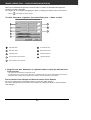
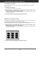
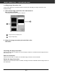
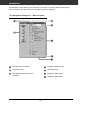
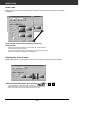
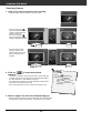
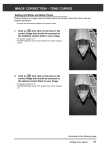
IMAGE CORRECTION — BRIGHTNESS/CONTRAST/COLOR BALANCE
1. Drag each Brightness, Contrast or Color balance
slider or input the desired value in the text box.
• The change will be reflected in the preview image.
• Moving the Brightness, Contrast or Color balance slider changes “PostCorrection Gray Scale” and “Post-Correction LUT”.
Post-Correction LUT
The color of the image is changed as shown in the PostCorrection LUT.
The correspondence between the color displayed on the PreCorrection Gray Scale and Post-Correction Gray Scale appears
on the Post-Correction LUT.
Auto setting
When the Auto setting button is clicked, the brightness and
contrast of the image is corrected automatically according to the
lightness without changing the color balance.
41
IMAGE CORRECTION — HUE/SATURATION/LIGHTNESS
When the Hue/Saturation/Lightness Correction button is clicked, the Hue/Saturation/Lightness
Correction window is displayed.
The images can be corrected by dragging the slider or inputting the desired value in the text box.
• Click on
in the Image Correction window.
The Hue, Saturation, Lightness Correction Dialog box — Name of parts
Hue-level slider
Hue-level text box
Saturation slider
Brightness text box
Lightness slider
Saturation text box
Pre-Correction Color Sample
Lightness text box
Post-Correction Color Sample
1. Drag the each Hue, Saturation or Lightness slider or input the desired value
in the text box.
• The change will be reflected in the preview image.
• To change the colour, move the Hue, Saturation or Lightness slider (or input the desired value in the text box).
• Moving the slider changes “Pre-Correction Color Sample” and “Post-Correction Color Sample”.
Pre-Correction Color Sample and Post-Correction Color Sample
The colour of the image is changed as shown in “Correction Color Sample”.
The colour displayed in “Pre-Correction Color Sample” is changed as shown in “Post-Correction
Color Sample”.
42
IMAGE CORRECTION — HUE/SATURATION/LIGHTNESS
Auto setting
When the Auto setting button is clicked, the saturation of the image is corrected automatically
without changing the hue and lightness.
Reset
If you click the Reset button, the settings in the current correction window are reset.
43
IMAGE CORRECTION – VARIATION CORRECTION
The variation frames are displayed around the corrected preview image. You can correct the image
while comparing with the variation images.
1. Click on
in the Image Correction window.
The Variations Dialog Box — Names of Parts
Variation Amount Control slider
Correction list box
Pre/Post Correction Image Display Area
Variation Amount Control text box
Limit Indication check box
Selecting the Correction Item
You can select from colour balance, brightness, contrast and saturation as the correction item to be
used in the variation correction. However, colour balance and saturation are not available when
using monochrome film.
1. Click on the arrow next to the correction item in the correction list box. The
available correction items are displayed.
2. Click the correction item.
• The variation frames are corrected according to the selected correction item.
44
IMAGE CORRECTION — VARIATION CORRECTION
Color Balance Correction
The 6 images that have been corrected by one-step in each RGBCMY direction for the center
image are displayed.
1. Click the colour balance.
• The corrected 6 frames of variation images are displayed.
2. Click the image in the direction you want to correct from the 6 frames of the
variation images except for the center image.
• The image you clicked is placed in thw centre and 6 new variation images that have been corrected by one-step
in each direction are displayed.
3. Correct the image by repeating the operation in step 2.
Brightness & Contrast Correction
The 8 images of which brightness and contrast have been corrected by one-step in horizontal and
vertical direction respectively for the center image are displayed.
The variation images on the left and lower sides of the center image show the – correction effect,
and on the right and upper sides of the center image show the + correction effect.
1. Click the image in the direction you want to correct from the 8 frames of the
variation images except for the center image.
• The image you clicked is placed in the centre and 8 new frames of the preview images that have been corrected
in each direction are displayed.
2. Correct the image by repeating the operation in step 1.
45
IMAGE CORRECTION — VARIATION CORRECTION
Saturation Correction
The 2 images of which saturation has been corrected on the right and left sides of the center image
are displayed . The variation image on the left side shows lower effect, and on the right side shows
higher effect.
1. Click the image in the direction you want to correct from the 2 frames of the
images except for the image in center.
• The image you clicked is placed in the centre and 2 new frames of the variation images that have been
corrected are displayed.
2. Correct the image by repeating the operation in
step 1.
Changing the Amount of Correction Step
The amount of correction step can be changed by moving the
Variation Amount Control slider. The desired amount can be also
input in the text box.
46
IMAGE CORRECTION — SNAPSHOT
When the Snapshot button is clicked, the current preview image is stored in the Snapshot Display
Area temporarily and displayed as a thumbnail.
When the thumbnail in the Snapshot Display Area is double-clicked, that image is displayed in the
preview window.
This allows a number of varying different corrections to be made and then compared without having
to go back and retrace previous correction steps.
Storing in the Snapshot Display Area temporarily
1. Click on
.
• The displayed preview image is displayed in the Snapshot Display Area
as a temporary storing place.
Snapshot Display Area 1
Displaying the image stored temporarily as a preview image
1. Click on the thumbnail in the Snapshot Display
Area.
• The displayed preview image is deleted and the thumbnail image is
displayed as a preview image.
Snapshot Display Area 2
47
Full-Screen View
This function allows you to display full screen the view of the corrected image in the image
correction window.
1. Click the Full-Screen View button.
• When the Pre/Post Correction Image Comparing Display button is clicked, the size of the pre and post correction
image is automatically changed according to the size of the main window.
Checking the Correction Result While Lining Up Images
When the Pre/Post Correction Comparison Display button is clicked, the image correction
windows are divided into right and left sides and pre-correction images are displayed in the left
side, and post-correction images are displayed in the right side.
48
IMAGE CORRECTION — JOB SAVE/JOB LOAD
The image correction setting in each correction window can be
saved as an image correction job. You can easily correct the
image by loading the apporopriate correction job.
Saving Image Correction Job
1. Click on the Image Correction Job Save button in
the Image correction tab.
• The Register Image Correction job dialog box is displayed.
2. Input the job name and click on the OK button.
• The current image correction setting is saved as an image correction job.
49
IMAGE CORRECTION — JOB SAVE/JOB LOAD
Loading Image Correction Job
This function allows you to load the saved correction job and apply an image correction to the
displayed image.
1. Click on the Image Correction Job Load button in
the correction window.
• The Image Correction Job List window is displayed.
Image Correction job display area
Original image display
2. Select the image correction job and click on the
OK button.
Canceling the Image Correction
When the Undo button is clicked, the current image correction is canceled and the image returns to
the previous one.
Redo the Correction
When the Redo button is clicked, the canceled image correction can be resumed.
Delete the Image Correction
When the Undo Correction button is clicked, all image correction is deleted and the image returns to
the initial state.
50
NAVIGATION
The Navigation window allows you to automat the procedure of scanning. When the Navigation
button is clicked in the Main window, the navigation window is displayed.
The Navigation Dialog box — Name of parts
Operation Item checkbox
Navigation Menu list box
Navigation Flow
Operation Items
APS Repeated Operation Item
checkbox
Navigation Start button
Navigation Stop button
51
NAVIGATION
Navigation Menu
This menu allows you to select the saved setting for automatic
operation. Not only the saved settings but the “Save Setting” and
“Delete Setting” items are displayed in this menu.
1. Select the operation items in the Operation Item
Checkbox or APS Repeated Operation Item
checkbox.
• The selected items are displayed with the buttons and arrows as a
Navigation Flow.
2. Click the Navigation Start button.
• To stop, click the Navigation Stop button.
Operation item checkbox
Insert the check mark in the operation items to be performed as
the automatic operation.
When using a film format other than APS, the index scan, film
frame selection and rewind cannot be selected.
1. Insert the check mark in the operation items to be
performed as the automatic operation.
APS repeated operation item checkbox
Insert the check mark in the items to be performed for all frames
of the images every time you execute the automatic operation.
When using a film format other than APS, the APS Repeated
Operation Item checkbox cannot be selected.
1. Insert the check mark in the operation items to be
performed for all frames of the images every time
you execute the automatic operation.
Operation items
The operation items in the automatic operation are displayed.
1. Select the details of the operation items with the
radio button or checkbox.
52
NAVIGATION
Saving, Selecting and Deleting a Navigation Setting
This function allows you to save the navigation settings.
The above settings can be saved, selected or deleted in the
Navigation Menu list box.
Saving a Navigation setting
1. Click on the arrow next to the Navigation menu
list to display the available menu.
2. Select saving setting.
• The Navigation set saving dialog box is displayed.
3. Input the setting name and click the OK button.
Selecting a Navigation setting
1. Click on the arrow next to the Navigation menu
list to display the available menu.
2. Select the setting to be used.
Deleting a Navigation setting
1. Click on the arrow next to the Navigation menu
list to display the available menu.
2. Select the setting to be deleted.
• The Navigation set deleting dialog box is displayed.
3. Select the setting to be deleted and click the
Delete button.
53
FINAL SCAN
Scan the film according to the Preview settings.
With the Dimâge Scan Elite utility software, you can save the final scan in one of the following file
formats.
JPEG
TIFF
BMP (Windows only)
PICT (Macintosh operating system only)
The 48 bit (16 bit each RGB) image file can be saved in the tiff format only.
Twain Driver Plug-in Software
With the Preview image displayed in the Preview window.
1. Click on
in the Main window.
• The final scan will begin.
• When scanning is complete, the final scan will appear in the host application.
2. Save the image using the instructions for your host application.
3. Close the Control Window to exit the Dimâge Scan Elite driver software.
• The driver window will close automatically after each scan if the Close Driver After Scanning option was selected
in the Preferences dialog box (p. 21).
Utility Software
With the Prescan image displayed in the Preview window.
1. Click on
in the Main window.
Your system’s standard save dialog box will appear.
2. Enter the desired file name and select the
file destination.
3. Select the file type from the drop-down
list.
4. Click on
.
• The final scan will begin.
• When scanning is complete, the scan will be saved in the selected
location. The software will return to the Preview window.
5. Close the Control Window to exit the Dimâge Scan
Elite driver software.
• The driver window will close automatically after each scan if the Close
Driver After Scanning option was selected in the Preferences dialog box
(p. 21).
54
SCANNING APS FILM
SCAN
FLOW
Launch Software
Specify the Film Type
Set Preferences
Load and Insert the Film
Holder
Index Scan
Select Frame(s) to
Prescan from Index
Print
OR
Select Frame(s) to
Prescan
Prescan
Orient and Crop
Correct the Contrast,
Brightness and Color
Specify the Job Type
Scan
Save
LAUNCH SOFTWARE SPECIFY FILM TYPE
1. Launch the software (pp. 18-19).
2. Select APS Cassette from the film format dropdown list in the main window.
3. Select the film type from the film type
drop-down list.
56
PREFERENCES – APS SETTINGS
1. Click on
in the Main window.
The preferences dialog is displayed.
2. Set the Preferences as desired in the APS settings part.
• De-select the Close Driver Software After Scanning check box when scanning multiple images at the same time.
Index Scan Priority
Speed – Creates a thumbnail representation of each frame on the roll.
Quality – Thumbnail and Preview images are created for each frame on the roll.
• Double-clicking on the index image opens the ready-made preview image.
Auto Film Rewind
Clicking on the eject button in the Command window automatically rewinds the film into
the APS cassette before the APS adapter is ejected.
Rotate All Frames 180°
Rotates all frames in the index window 180°.
57
APS ADAPTER (OPTIONAL)
The AD-10 APS Adapter is an optional accessory. The Dimâge Scan Elite can not scan
Advanced Photo System film (IX-240 type) without the AD-10 APS Adapter.
Names of Parts
Film-chamber door
Film-chamber release
Scanner contacts*
* Do not touch
Loading the APS Adapter
1. Slide the film-chamber release as shown.
• The film-chamber door will open.
2. Insert the film cassette into the film chamber
with the VEI (Visual Exposure Indicator) on top.
3. Close the film-chamber door.
• The film-chamber door will not close if the
mark is not highlighted.
Forcing the door shut could damage the cassette.
58
APS ADAPTER (OPTIONAL)
Inserting the APS Adapter
1. Press the door where
shown to unlock,
…then open the scanner’s film door.
2. Insert the APS Adapter into the scanner.
59
INDEX SCAN
Index scan displays a scan of each image on the cassette in the index scan window. The time
required for an index scan depends on the performance of your machine.
If you don’t want to index scan the entire roll, select the frame number of the image you want
to scan from the index print provided by your photofinisher. Click on the appropriate image box
in the index window to select an image for prescanning or scanning.
• There are two options for making an index scan, Speed or Quality. Select the desired option in the Preference
dialog box (p. 57).
Index Window – Names of Parts
Reverse frame order button
Frame number
Rotate left button
Index Image frame
Rotate right button
Image Correction Job Load button
Flip Horizontal button
Flip Vertical button
Index Load button
Full-Screen View button
Save Index Scan button
Index imag
60
INDEX SCAN
Index scan
Click on
in the Main window.
• All frames on the cassette will be scanned and appear in the Index
window.
Click on
to
reverse the
display order.
• To cancel th
e index scan,
press the
escape key (
-• Command
and
period for the
Macintosh) un
til the
Cancelling In
dex Scan mes
sage box
appears.
• The complet
ed index scan
s will
appear in the
index window.
• Frames that
have not been
index
scanned can
still be select
ed for
prescanning
and scanning
.
61
INDEX SCAN
Index scan
Change the size of the Index scan window as desired. The position of the frames will change
accordingly.
Click on the corner tab and drag to reach the
desired size.
• When the Full-Screen View button is not clicked, the size and shape of
the index frames does not change.
• When the Full-Screen View button is clicked, the size of the index frames
changes automatically and all frames are displayed.
Rotating the Index Frames
Rotate index frames so they appear in the index scan window with the proper orientation.
Select the desired frames, then click on
,
• The selected frames will rotate in 90° increments
either clockwise or counter-clockwise or flip vertically or horizontally.
• Rotating the index frame will not affect the Preview or Scan.
62
or
,
.
PREVIEW AND IMAGE CORRECTION
1. Click on an image or an image box, then click on
prescanned, then opened in the Preview window.
Click here to specify an
APS format (C, H, or P)
cropping frame.
2. Orient and crop the image as desired (pp. 29-33).
3. Apply contrast, brightness, and colour corrections
(pp. 34-46).
4. Select the desired job type (pp.71-72).
• Only one job type can be selected when multiple images are scanned at
the same time.
5. Close the Preview window to return to the Index
window.
• Adjustments made in the Preview window are held until the image is
scanned or the driver software is closed.
63
. The image will be
SCANNING THE IMAGE
Selecting Frames
1. Click on an image to select it for scanning.
• Selected images are surrounded by a dark gray frame.
• Press the control key (
key for the Macintosh) while
clicking to select additional
frames for scanning.
• Press the control key (
key for the Macintosh) while
clicking to deselect an image.
CLICK
CLICK
CLICK
CLICK
• Press the shift key while
clicking to select all the
frames between the current
frame and the last frame
selected.
2. Click on
image(s).
to scan the selected
• The scan is cancelled if more than the number of frames selected
is greater than the Max # of Frames set in the Preferences dialog
box. See Preferences - APS Settings on page 57.
• The image will be opened in your photo application software when
the scanner’s driver software is closed.
• Some photo applications can only acquire one image at a time.
3. Refer to page 54 to save the scanned image(s).
• Multiple scans will be saved using the selected file name and numbered
chronologically. Example: File_Name01, File_Name02, File_Name03...
64
Click on
to save the
index as an im
age file.
• The image
can be saved
in
JPEG or BMP
format
(JPEG or PIC
T format for th
e
Macintosh).
REMOVING THE APS ADAPTER
1. Click on
to rewind the film into the cassette.
• This step is not necessary when the auto rewind option is selected in
the Preference dialog box window (p. 49).
2. Remove the APS adapter from the scanner and
close the film door.
3. Close the Control Window to exit the
Dimâge Scan Elite driver software.
• The driver window will close automatically after each scan if
the Close Application After Scanning option was selected in
the Preferences dialog box (p.21).
4. Open the APS adapter’s film chamber
door and remove the cassette.
65
Multiple imag
es can be
scanned befo
re closing the
software.
• Some photo
applications
can only acqu
ire one
image at a tim
e.
66
APPENDIX
COLOR MATCHING
This function allows you to match the scanner data to the monitor type (colour space).
The output colour space and ICC profile can be specified by using the colour matching function.
To match the scanner data to the colour space, specify the output colour space.
To correct the color reproduction character of the monitor and to reduce the difference of color
between monitors in different environments in addition to the color space setting, specify the
monitor ICC profile settings in both the driver software and a software such as Photoshop. For
details, refer to page 69.
1. Click on
in the Main window.
The Color Matching in the Preference Dialog Box — Name of parts
Color Matching ON checkbox
ICC profile setting checkbox
ICC profile text box
Output Color Space list box
ICC profile Load button
2. Set the preferences as desired.
• De-select the Close Driver After Scanning check box when scanning
multiple images at the same time.
68
When the colo
r
matching func
tion
is used, the
processing tim
e
may be longer
.
COLOR MATCHING
Output colour space setting
1. Insert the check mark in the “Color Matching ON”
box.
2. Click the
(menu) button in the output colour
space list box, the available output colour space
settings are displayed.
3. Click the desired output colour space setting.
ICC profile setting
1. Insert the check mark in the “use ICC profile” box.
2. Click the Load button.
• The standard file open dialog of your operating system is displayed.
3. Select the ICC profile according to the monitor
being used.
The application may perform the original matching process. If you want to change the setting,
refer to the following sample settings.
When the colour matching function is used, the colour matching function of the OS, video card,
etc. are disabled.
When using Photoshop Ver.3.0.5 or Ver. 4.0.1
Output colour space:
ICC profile*1):
Apple RGB
select (for Windows)
This is not used (for Macintosh)
When using an application of which the monitor colour matching function is set to
ON
Output colour space*2):
ICC profile*1):
option
select
When using an application of which the monitor colour matching function is set to
OFF, or when using an application which does not have the monitor colour
matching function.
Output colour space:
do not specify
select
ICC profile*1):
When an image is scanned with this setting, the data is matched according to the monitor
being used.
*1) ICC profile specifies the ICC profile of the monitor.
*2) The same color space as specified in the application is specified.
69
SCAN SETTINGS
The scan settings determine your final image’s resolution, dimensions, and file size, as well as
helping determine the image quality. You can select a Job (p. 71) to have the scan settings selected
for you or you can directly enter them into the Main window (Index window or Preview window).
The Scan Settings part in the Main Window — Names of parts
Except the Image Correction window in the Main window.
Job Name list box
Units list box
Input Resolution list box
Image size display
Output Resolution list box
Job Load button
Input Size text box (W)
Job Registry button
Input Size text box (H)
Input Size lock button
Magnification text box
Output Size lock button
Output Size text box (W)
Reset button
Output Size text box (H)
70
SCAN SETTINGS
Image resolution is the number of pixels per inch (ppi or dpi) that represent your scanned image.
The size of an image file is determined by its size (dimensions) and resolution.
The rule to follow when scanning is "bigger is better". To obtain the best results, set the output
resolution to the highest value your final output device (printer, monitor, etc.) can handle. The driver
software automatically determines the input resolution necessary to obtain the desired output size
and resolution.
1. Click on
in the Index window.
The Job Selection dialog box will appear.
2. Select the appropriate category from the
drop-down list.
3. Click on the job file name to select it, then
click on
.
• The settings are applied to the active Preview
window.
Job names ca
n be listed
chronologically
or
Select the form alphabetically.
at by clicking
on
the Name or
Date option bu
tton.
• The cropping
frame change
s
accordingly, bu
t can be
propor tionally
resized.
Continued on the following page.
71
SCAN SETTINGS
4. Enter the desired output resolution from the
output resolution drop-down list.
• Values can also be entered into the output resolution list box directly.
• The output resolution cannot be changed when the unit list box is set
to pixels.
5. The dimensions of the cropping frame are
displayed in the input size text boxes.
• Values can be entered directly or by resizing the cropping frame.
• The values will change if a different unit of measure is selected.
• The scanning area size can't be changed if the Input Size is locked.
6. Enter the desired output size (maximum 3 digits).
• The output size is limited by the maximum resolution of the scanner.
• The values will change if a different unit of measure is selected.
• The output size cannot be changed when the unit list box is set to
pixels.
• The scanning area size can be changed proportionally (within the
resolution limits) when the Output Size is locked.
• Click on
to lock the se
ttings.
The icon will
change to
.
Click again to
unlock.
• The magnific
ation text box
displays the ou
tput/input size
ratio as a perc
entage.
• Magnificatio
n values can
be
entered direct
ly.
7. The input scan resolution text box is set to the
lowest input (scan) resolution necessary to
achieve the desired output size and resolution.
• Input scan resolutions can also be selected from the drop down list
or entered directly.
72
CREATING / DELETING JOB FILES
Creating a Job
In addition to the Job settings included with the software, it is possible to create and save your
own Job settings.
1. Set the desired settings in the Main window (Index
window or Preview window).
2. Click on
.
The Job Registry dialog box will appear
3. Name the job by entering a title and select the
desired category, then click on
.
Deleting a Job
It is possible to delete the Job you created when it is no longer needed.
Click on the name of the job in the
Main window scan settings part,
then press the delete key on your
keyboard.
73
SCAN JOB TYPE
Before making the final scan, the scanner needs to know how big the final image will be and
the quality of output that will be used (printer, monitor, etc.) so it knows what resolution to scan
the film. Using the Job function is a quick and easy way to enter the scan settings.
Scan Job Category
Description
Custom
User created scan settings (p. 71).
Color Laser
Printer
Digital colour copiers and colour laser printers
Uses output resolution of 400 or 600 dpi. There are two
paper-size options; letter and A4.
Photosensitive
Printers that use photosensitive/photographic material
Can use output resolutions of 400 dpi, 360 dpi, 267 dpi,
and 180 dpi. There are ten paper size options.
Dye-Sub Printer
Dye-sublimation printers
Uses an output resolution of 300 dpi. There are 4 paper
size options.
Ink Jet Printer
Uses an output resolution of 200 dpi. There are 4 paper
size options.
Web Page
For use on home pages
Image size is listed in pixels and will vary. Standard
Photo CD sizes are also available.
Screen
For monitor display
Image size is listed in pixels and will be the VGA
standard of 640 x 480 pixels or larger.
Document
For insertion into documents
Uses an output resolution of 72 dpi. Image size depends
on the paper size selected.
Film Recorder
Default
For high input resolution images that will be output to a
film recorder.
This category uses the default settings for the film
format. The scan settings appear in the Job Selection
window.
74
SCAN JOB FILE LIST – 35MM
For your reference, the following is a listing of the scan job categories and names for the 35mm and
APS film formats.
Category
Job name
Default
Default
Color Laser Printer Max Size_600dpi
Photosensitive
Dye-Sub Printer
Ink-Jet Printer
A4Quarter_600dpi
A4Eighth_600dpi
Letter Quarter_600dpi
Letter Eighth_600dpi
Max Size_400dpi
A4Half_400dpi
A4Quarter_400dpi
A4Eighth_400dpi
Letter Half_400dpi
Letter Quarter_400dpi
Letter Eighth_400dpi
Max Size
A5_400dpi
8x10_400dpi
5x7_400dpi
PostCard4 6_400dpi
Letter_267dpi
A4_267dpi
A5_267dpi
8x10_267dpi
5x7_267dpi
PostCard4 6_267dpi
(unavailable)
2L_360dpi
14x17_180dpi
11x14_180dpi
10x12_180dpi
(unavailable)
2L_180dpi
A4Full
A4Half
A4Quarter
A4Eighth
Letter Full
Letter Half
Letter Quarter
Letter Eighth
(unavailable)
Photo4x6
Photo3x5 /Photo9x13
A4Full
A4Half
A4Quarter
A4Eighth
Letter Full
Letter Half
Letter Quarter
Letter Eighth
(unavailable)
Photo4x6
Photo3x5 /Photo9x13
Resolution
In
Out
705
2820
2447
1735
2291
1702
2820
2313
1629
1156
2291
1526
1133
2820
2313
2798
1961
1678
2039
2187
1545
1870
1307
1120
1597
1727
2123
1747
1494
797
857
2455
1735
1223
866
2291
1714
1144
850
1223
1240
1049
163
1156
814
577
1526
1144
763
566
814
826
699
300
600
600
600
600
600
400
400
400
400
400
400
400
400
400
400
400
400
267
267
267
267
267
267
360
360
180
180
180
180
180
300
300
300
300
300
300
300
300
300
300
300
200
200
200
200
200
200
200
200
200
200
200
Mag.
Unit
Input Size
W
H
235
470
407
289
381
283
705
578
407
289
572
381
283
705
578
699
490
419
763
819
578
700
489
419
443
479
1179
970
830
442
476
818
578
407
289
763
571
381
283
407
413
349
818
578
407
288
763
572
381
283
407
413
349
pixel
mm
mm
mm
inch
inch
mm
mm
mm
mm
inch
inch
inch
mm
mm
inch
inch
inch
inch
mm
mm
inch
inch
inch
mm
mm
mm
mm
mm
mm
mm
mm
mm
mm
mm
inch
inch
inch
inch
mm
mm
mm
mm
mm
mm
mm
inch
inch
inch
inch
mm
mm
mm
1008
36.3
36.3
36.3
1.43
1.43
36.3
36.3
36.3
36.3
1.42
1.43
1.43
36.3
36.3
1.43
1.43
1.43
1.43
36.3
36.3
1.43
1.43
1.43
36.3
36.3
36.3
36.3
36.3
36.3
36.3
36.3
36.3
36.3
36.3
1.43
1.43
1.43
1.43
36.3
36.3
36.3
36.3
36.3
36.3
36.4
1.42
1.42
1.43
1.43
36.3
36.3
36.3
672
24.2
24.2
24.2
0.95
0.95
24.2
24.2
24.2
24.2
0.95
0.95
0.95
24.2
24.2
0.95
0.95
0.95
0.95
24.2
24.2
0.95
0.95
0.95
24.2
24.2
24.2
24.2
24.2
24.2
24.2
24.2
24.2
24.2
24.2
0.95
0.95
0.95
0.95
24.2
24.2
24.2
24.2
24.2
24.2
24.3
0.95
0.95
0.95
0.95
24.2
24.2
24.0
Input
Lock
OFF
OFF
OFF
OFF
OFF
OFF
OFF
OFF
OFF
OFF
OFF
OFF
OFF
OFF
OFF
OFF
OFF
OFF
OFF
OFF
OFF
OFF
OFF
OFF
OFF
OFF
OFF
OFF
OFF
OFF
OFF
OFF
OFF
OFF
OFF
OFF
OFF
OFF
OFF
OFF
OFF
OFF
OFF
OFF
OFF
OFF
OFF
OFF
OFF
OFF
OFF
OFF
OFF
Output Size
W
H
1008
170.00
148.00
105.00
5.46
4.05
256.00
210.00
147.00
105.00
8.19
5.45
4.05
256.00
210.00
10.00
7.01
6.00
10.90
297.00
210.00
10.00
7.00
6.00
161.00
174.00
428.00
352.00
301.00
160.00
173.00
297.00
210.00
148.00
104.00
10.90
8.17
5.45
4.05
148.00
150.00
127.00
297.00
210.00
148.00
105.00
10.90
8.17
5.45
4.05
148.00
150.00
127.00
672
113.00
98.70
70.00
3.64
2.70
170.00
140.00
98.00
69.90
5.46
3.63
2.70
170.00
140.00
6.66
4.67
4.00
7.27
198.00
140.00
6.67
4.66
4.00
107.00
116.00
285.00
235.00
200.00
106.00
115.00
198.00
140.00
98.70
69.90
7.28
5.44
3.63
2.70
98.70
100.00
84.60
198.00
139.00
98.50
69.80
7.27
5.45
3.63
2.70
98.50
100.00
84.50
Output
Lock
OFF
ON
ON
ON
ON
ON
ON
ON
ON
ON
ON
ON
ON
ON
ON
ON
ON
ON
ON
ON
ON
ON
ON
ON
ON
ON
ON
ON
ON
ON
ON
ON
ON
ON
ON
ON
ON
ON
ON
ON
ON
ON
ON
ON
ON
ON
ON
ON
ON
ON
ON
ON
ON
Continued on the following page.
75
SCAN JOB FILE LIST – 35MM
Category
Web Page
Screen
Document
Film Recorder
Job Name
1023 x 682
960 x 640
870 x 580
768 x 512
624 x 416
600 x 400
480 x 320
Photo CD 2048 x 3072
Photo CD 1024 x 1536
Photo CD512 x 768
Photo CD256 x 348
1280 x 1024
1280 x 960
1152 x 870
1024 x 768
832 x 624
800 x 600
640 x 480
A4 Half
A4 Quarter
A4 Eighth
Letter Half
Letter Quarter
Letter Eighth
35mm Full-Frame
35mm Half-Frame
35mm Quarter-Frame
Resolution
In
Out
716
671
608
537
436
419
335
2148
1074
537
243
895
895
805
716
582
559
47
416
293
207
411
274
203
2382
1586
1189
300
300
300
300
300
300
300
300
300
300
300
300
300
300
300
300
300
300
72
72
72
72
72
72
2400
2400
2400
Mag.
Unit
Input Size
W
H
238
223
202
179
145
139
111
716
358
179
81
298
298
268
238
194
186
149
577
406
287
570
379
281
99
66
49
pixel
pixel
pixel
pixel
pixel
pixel
pixel
pixel
pixel
pixel
pixel
pixel
pixel
pixel
pixel
pixel
pixel
pixel
mm
mm
mm
inch
inch
inch
mm
mm
mm
1023
960
870
768
624
600
480
3072
1536
768
348
1280
1280
1152
1024
832
800
640
36.3
36.4
36.4
1.43
1.43
1.44
36.30
36.30
36.7
76
682
640
580
512
416
400
320
2048
1024
512
232
853
853
768
682
554
533
426
24.2
24.1
24.3
0.95
0.95
0.96
24.20
24.20
24.40
Input
Lock
OFF
OFF
OFF
OFF
OFF
OFF
OFF
OFF
OFF
OFF
OFF
OFF
OFF
OFF
OFF
OFF
OFF
OFF
OFF
OFF
OFF
OFF
OFF
OFF
OFF
OFF
OFF
Output Size
W
H
1023
960
870
768
624
600
480
3072
1536
768
348
1280
1280
1152
1024
832
800
640
210.00
148.00
105.00
8.16
5.44
4.04
36.00
24.00
18.00
682
640
580
512
416
400
320
2048
1024
512
232
853
853
768
682
554
533
426
139.00
98.40
70.00
5.44
3.62
2.69
24.00
16.00
11.90
Output
Lock
ON
ON
ON
ON
ON
ON
ON
ON
ON
ON
ON
ON
ON
ON
ON
ON
ON
ON
ON
ON
ON
ON
ON
ON
ON
ON
ON
SCAN JOB FILE LIST – APS
Category
Job name
Default
Default
Color Laser Printer Max Size_600dpi
Photosensitive
Dye-Sub Printer
Ink-Jet Printer
Web Page
Screen
Document
A4 Eighth_600dpi
Letter Eighth_600dpi
Max Size_400dpi
A4 Half_400dpi
A4 Quarter_400dpi
A4 Eighth_400dpi
Letter Quarter_400dpi
Letter Eighth_400dpi
Max Size
A5_400dpi
5x7_400dpi
Post Card 4 x 6_400dpi
Letter_267dpi
A4_267dpi
A5_267dpi
8x10_267dpi
5x7_267dpi
PostCard4 x 6_267dpi
(unavailable)
2L_360dpi
14x17_180dpi
11x14_180dpi
10x12_180dpi
(unavailable)
2L_180dpi
Max Size
A4 Half
A4 Quarter
A4 Eighth
Letter Full
Letter Half
Letter Quarter
Letter Eighth
(unavailable)
Photo 9x13
A4 Full
A4 Half
A4 Quarter
A4 Eighth
Letter Full
Letter Half
Letter Quarter
Letter Eighth
Photo 4 x 6
Photo 3.5 x 5/Photo 9 x 13
1280 x 739
1152 x 665
1024 x 590
832 x 480
800 x 461
640 x 369
Photo CD1024 x 1536
Photo CD512 x 768
Photo CD256 x 348
1280 x 1024
1280 x 960
1152 x 870
1024 x 768
832 x 624
800 x 600
640 x 480
A4 Half
A4 Quarter
A4 Eighth
Letter Half
Resolution
In
Out
705
2820
2104
2161
2820
2809
1977
1401
1851
1440
2820
2809
2374
2039
2472
2654
1870
2263
1586
1359
1935
2092
2578
2117
1809
966
1046
2820
2104
1482
1050
2776
2161
1385
1080
1500
1270
1977
1401
987
700
1846
1440
924
720
1001
846
1085
976
867
705
678
542
1303
650
294
1085
1085
976
867
705
678
542
504
355
251
518
300
600
600
600
400
400
400
400
400
400
400
400
400
400
267
267
267
267
267
267
360
360
180
180
180
180
180
300
300
300
300
300
300
300
300
300
300
200
200
200
200
200
200
200
200
200
200
300
300
300
300
300
300
300
300
300
300
300
300
300
300
300
300
72
72
72
72
Mag.
Unit
235
470
350
360
705
702
494
350
462
360
705
702
593
509
925
994
700
847
594
508
537
581
1432
1176
1005
536
581
940
701
494
350
925
720
461
360
500
423
988
700
493
350
923
720
462
360
500
423
361
665
239
235
226
180
434
216
98
361
361
325
289
235
226
369
700
493
348
719
pixel
mm
mm
inch
mm
mm
mm
mm
inch
inch
mm
mm
inch
inch
inch
mm
mm
inch
inch
inch
mm
mm
mm
mm
mm
mm
mm
mm
mm
mm
mm
inch
inch
inch
inch
mm
mm
mm
mm
mm
mm
inch
inch
inch
inch
mm
mm
pixel
pixel
pixel
pixel
pixel
pixel
pixel
pixel
pixel
pixel
pixel
pixel
pixel
pixel
pixel
pixel
mm
mm
mm
inch
77
Input Size
W
H
832
29.9
30.0
1.18
29.9
29.9
30.0
30.0
1.18
1.18
29.9
29.9
1.18
1.18
1.18
29.9
30.0
1.18
1.17
1.18
30.0
29.9
29.9
29.
29.9
30.0
29.9
29.9
29.9
29.9
30.0
1.18
1.18
1.18
1.18
30.0
30.0
30.0
30.0
30.0
30.0
1.18
1.18
1.17
1.18
30.0
30.0
1280
1152
1024
832
800
640
1536
768
348
1280
1280
1152
1024
832
800
640
30.0
30.0
30.0
1.18
480
17.2
17.3
0.68
17.2
17.2
17.3
17.3
0.68
0.68
17.2
17.2
0.68
0.68
0.68
17.2
17.2
0.68
0.68
0.68
17.3
17.2
17.2
17.2
17.2
17.2
17.2
17.2
17.3
17.2
17.3
0.68
0.68
0.68
0.68
17.2
17.2
17.3
17.3
17.3
17.3
0.68
0.68
0.68
0.68
17.3
17.2
739
665
590
480
461
369
887
443
200
739
739
665
590
480
461
369
17.3
17.3
17.3
0.68
Input
Lock
OFF
OFF
OFF
OFF
OFF
OFF
OFF
OFF
OFF
OFF
OFF
OFF
OFF
OFF
OFF
OFF
OFF
OFF
OFF
OFF
OFF
OFF
OFF
OFF
OFF
OFF
OFF
OFF
OFF
OFF
OFF
OFF
OFF
OFF
OFF
OFF
OFF
OFF
OFF
OFF
OFF
OFF
OFF
OFF
OFF
OFF
OFF
OFF
OFF
OFF
OFF
OFF
OFF
OFF
OFF
OFF
OFF
OFF
OFF
OFF
OFF
OFF
OFF
OFF
OFF
OFF
OFF
Output Size
W
H
832
140.00
105.00
4.25
211.00
210.00
148.00
105.00
5.46
4.25
211.00
210.00
7.00
6.01
10.90
297.00
210.00
10.00
7.00
6.00
161.00
174.00
429.00
352.00
301.00
160.00
174.00
281.00
210.00
148.00
105.00
10.90
8.50
5.45
4.25
150.00
127.00
297.00
210.00
148.00
105.00
10.90
8.50
5.45
4.25
150.00
127.00
1280
1152
1024
832
800
640
1536
768
348
1280
1280
1152
1024
832
800
640
210.00
148.00
105.00
8.50
480
81.20
60.60
2.45
121.00
121.00
85.40
60.60
3.15
2.45
121.00
121.00
4.04
3.47
6.30
171.00
121.00
5.76
4.04
3.46
92.90
100.00
247.00
203.00
173.00
92.70
100.00
162.00
121.00
85.40
60.50
6.30
4.90
3.14
2.45
86.40
73.00
171.00
121.00
85.30
60.40
6.28
4.90
3.14
2.45
86.40
73.00
739
665
590
480
461
369
887
443
200
739
739
665
590
480
461
369
121.00
85.00
60.30
4.90
Output
Lock
OFF
ON
ON
ON
ON
ON
ON
ON
ON
ON
ON
ON
ON
ON
ON
ON
ON
ON
ON
ON
ON
ON
ON
ON
ON
ON
ON
ON
ON
ON
ON
ON
ON
ON
ON
ON
ON
ON
ON
ON
ON
ON
ON
ON
ON
ON
ON
ON
ON
ON
ON
ON
ON
ON
ON
ON
ON
ON
ON
ON
ON
ON
ON
ON
ON
ON
ON
GLOSSARY
BRIGHTNESS
CHANNEL
CONTRAST
CROP
DPI
EMULSION SIDE
GAMMA
HIGHLIGHTS
HISTOGRAM
INTERPOLATION
JPEG
MIDTONE
NEUTRAL
PICT
PIXEL
The lightness or darkness of the image.
The component of an image. Your scanned image has three
channels: red, green, and blue (RGB).
The gradation of shades in an image. A high contrast image
has very dark areas and bright areas without many middle
shades. A low contrast image has many tones that are close to
the same brightness. Low contrast images are often described
as looking ‘flat’.
To trim and delete the unwanted edges of the image.
Dots (pixels) per inch.
The side of the film coated with the photographic material.
The contrast of only the middle tones.
The lighter areas of the image.
A graph showing the amount of each level of the 256
brightness levels.
A form of adding new pixels in an image when resampling up.
The JPEG (Joint Photographic Experts Group) compression
standard is capable of producing a high compression ratio
while maintaining image quality. JPEG is a widely supported
image file format.
The middle shades of an image, in between light and dark.
Having no colour cast, such as black, white, or gray.
(Macintosh operating system only) The PICT graphic file format
uses a lossless compression scheme and is compatible with
many Macintosh applications.
Abbreviation for picture element. The dots that make up an
electronic image.
78
GLOSSARY
RESAMPLE
RESOLUTION
RGB
SHADOWS
TIFF
WINDOWS® BMP
To change the number of pixels in the image. If pixels are
discarded when shrinking an image, it is called resampling
down. If new pixels are created in an image, it is called
resampling up.
The number of pixels in a given area of the image; such as
pixels per inch or pixels per centimeter. High resolution is the
term for an image with a lot of pixels in a given area. Low
resolution means there are not many pixels in a given area.
Red, Green, and Blue. These are the colours of the three
channels that make up the scanned image. Monitors use red,
green, and blue phosphors to create the image you see on the
screen.
The dark areas of an image.
Tagged Image File Format (TIFF) files contain bit-mapped
data. In addition to being a widely supported format, TIFF is
able to handle the colour palette needed for professionalquality images and graphics.
(Windows only)The BMP graphic file format is for bit-mapped
images. BMP images are supported by the Paint accessory
and can easily be opened on most PCs running Windows.
79
TROUBLE SHOOTING
SYMPTOM or MESSAGE
SOLUTION
The computer will not start up
after connecting the scanner.
• Shut down the computer and all the devices in
your SCSI chain, then check the SCSI cables,
SCSI ID connection, power cord, and SCSI ID.
DS_Elite does not appear in
the Import drop down list.
• Make sure the plug-in module has been
placed in the correct folder. See page 12.
“Could not establish
connection with scanner.”
• Indicator lamp is off - Turn the Dimâge Scan
Elite on, then restart your system.
• Check that the SCSI ID is not being used by
another SCSI device.
“Setting up now. Remove the
film holder.”
• Remove the film holder and click on OK.
Indicator lamp blinking
rapidly (8Hz).
• Scanner door opened during setup. Close
scanner door.
“Set film properly…”
• Load film into the film holder.
“Set 35mm film holder
properly.”
• Set the correct film type.
“Set APS film holder properly.”
• Set the correct film type.
“Could not recognize the
film type.”
• Set the film type manually.
“Insufficient Memory”
• Increase the memory requirements for the
host application.
• If you have scanned multiple images, close
and relaunch the host application.
“Setting up now. Remove
the film holder.” appears
when the film holder is not
loaded.
• Contact a Minolta Service Facility to change
the fluorescent lamp.
80