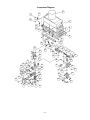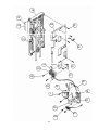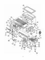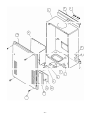
1
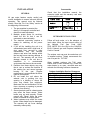
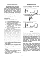
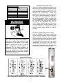
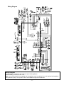
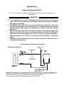
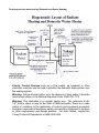
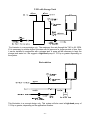
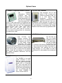
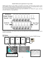
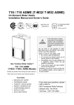
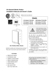
T-M1
Instantaneous Water Heater
Installation Manual and Owner’s Guide
WARNING
This product must be installed and
serviced by a licensed plumber, a licensed
gas fitter, or a professional service
technician and/or in accordance with all
local code. Improper installation and/or
operation, or installation by an unqualified
person, will void the warranty.
WARNING
Mobius Water Heater™
Model T-M1.
Operation of this unit creates carbon
monoxide gas and flue gases which can
cause serious injury or death. In addition,
if the information in this manual is not
followed exactly, a fire or explosion may
result causing property damage, personal
injury or death.
Suitable for potable water heating and space heating
FEATURING
•
•
•
•
•
•
•
ENDLESS HOT WATER
ON DEMAND
COMPACT, SPACE SAVING
ENERGY CONSERVING
COMPUTER CONTROLS
COMPUTERIZED SAFETY
NO PILOT LIGHT
Takagi Industrial Co. USA Inc.
5 Whatney
Irvine, CA 92618
Toll Free (888) 882-5244 USA
Toll Free (877) 877-4953 CANADA
www.Takagi.com
SPECIFICATIONS
CONTENTS
Specification
…………. 2
Introduction
…………..3
For your safety
…………..3-4
Natural Gas Input
Min. 25,000 Btu
Max. 235,000 Btu
LPG Input
Min. 25,000 Btu
Max. 225,000 Btu
Gas Connection
Water Connection
Installation
…………. 5
• General
…………. 5
• Accessories
…………. 5
• Outdoor Installation
………….5-6
• Indoor Installation
………….6-7
• Venting Instructions
…………..7 -9
• Gas Supply/Gas Pipe sizing………..10-11
• Water Connection
…………. 11-12
• Electrical Connection
…………. 12
• Initial operation
…………. 13
¾” NPT
¾” NPT
Water Pressure
Min. 15 psi
Max. 150 psi
Natural Gas Pressure Inlet
LP Gas Pressure Inlet
Normal operation
…………. 13
• Flow
…………. 13
• Temperature setting
…………. 14
• Wiring diagram
…………. 15
• Freeze Protection Device …………. 16
• Maintenance and Service …………..16-17
• Error codes
…………..17
Min. 5” WC
Max. 10.5” WC
Min. 11” WC
Max. 14” WC
Manifold Pressure
Natural 2.2” WC
Propane 2.7” WC
Weight
Dimensions
Ignition
Electrical Supply
70 lbs.
23.6”x18.5”x8.9”
Electronic Ignition
AC 120 V
For your Safety
…………..18
Danger
…………..19
•
Application
• Space Heating
• Dual-purpose heating
• Storage Tank
• Re-Circulation
…………..20
…………..20
…………..21
…………..22
…………..22
•
Optional Items
…………..23
Manifold Multi-system
…………24-26
Component Diagram
…………27-30
Parts list
…………31-32
Output temperature Chart
…………..33
*** NOTE ***
Check the rating plate to ensure this
product matches your specifications;
This appliance is certified for use at
altitudes from 0ft to 4500ft (1,370m) in
accordance to the latest CAN/CGA 2.17High Altitude Installation procedures at
normal
manifold
pressure
2.2"
W.C. (Natural Gas). Do not alter the orifice
jets or gas supply pressure. At altitudes of
4500ft to 5,000ft (1524m) lower the
manifold pressure to 2.0" W.C. (Natural
Gas). At 5000ft to 6000ft (1,829m), lower
the manifold pressure to 1.9" W.C. (Natural
Gas). For elevations above 6000ft or for
specific instructions on how to lower the
manifold pressure, please call the Takagi
office
Manufacturer reserves the right to discontinue, or change at any time, specifications or
designs without notice and without incurring obligations.
-2-
INTRODUCTION
FOR YOUR SAFETY
The installer is responsible for the correct
installation of your Mobius T-M1 Water
Heater. Installation and service must be
performed by a qualified installer (for
example, a licensed plumber or gas fitter)
otherwise the warranty by Takagi will be
void.
This manual provides information necessary
for the installation, operation, and maintenance
of the Model T-M1 water heater. This unit
includes a fan enabling sidewall (power)
venting and an advanced electronic ignition
system.
The model description is listed on the rating
plate which is attached to the front cover of the
water heater. Please read all installation
instructions completely before installing this
product.
If you have any problems or
questions regarding this equipment, consult
with Takagi or its local representative.
Experiences have shown that most operating
problems are caused by improper installation.
PLEASE READ THIS MANUAL CAREFULLY
AND FOLLOW ALL DIRECTIONS.
1. Follow all local codes, or in the absence of
local codes, follow the most recent edition
of the National Fuel Gas Code, ANSI
Z223.1/NFPA 54 in the USA or the
CAN/CSA B149.1 Natural Gas and
Propane Installation Code in Canada.
2. Properly ground the unit in accordance with
all local codes or in the absence of local
codes, with the National Electrical Codes,
ANSI/NFPA 70 in the USA or CSA
standard C22.1 Canada Electrical Code
Part 1 in Canada.
3. Carefully plan where you intend to install
your T-M1 Water Heater. Ensure that your
heater will have enough combustible air
and proper ventilation and locate your
heater where water leakage will not do
damage to surrounding areas. If there is a
possibility of water damage, install a
suitable drain pan under the unit which will
not restrict combustible airflow.
4. Check the rating plate for the correct gas
type, gas pressure, water pressure and
electrical rating. If this unit does not match
your requirements, do not install.
The T-M1 Water Heater is an instantaneous,
tankless water heater designed to supply
endless hot water to your entire household
and/or commercial facility utilizing total
efficiency. The principle behind the T-M1
Water Heater is simple. Once you open a hot
water tap, water flows through the T-M1 Water
heater. Once a minimum of 0.75 GPM is
achieved, the flow sensor automatically
commands the computer to turn on the fan,
activate the electronic igniter and open the gas
valves. The computer monitors water
temperature, water flow rate and gas flow to
ensure that you get the right amount of hot
water at the correct hot water temperature.
After the burners are ignited, the “fire on” lamp
is lit. The computer will modulate the gas
supply valve and water flow. 0.75 gallons per
minute is required to turn the burners on; after
the burners are ignited, the flow rate can be
lowered to 0.6 gallons per minute to maintain
the heater on. It is advisable to open further
the cold tap rather than decreasing the hot tap
to adjust the water temperature. As long as
you have water, gas and electricity, you will get
an endless flow of hot water. Open a hot water
tap to turn on your water heater. Close the tap
to turn off your water heater.
Rating plate
5. If any problem should occur, turn off all hot
water taps and turn off the gas. Then call a
trained technician or the Gas Company or
the manufacturer.
-3-
6. WARNING: Do not disconnect the
electrical supply if the ambient temperature
will drop below freezing. The Freeze
Prevention Device only works if the unit
has electrical power. The Freeze
Prevention Device is rated for temperatures
down to 5 ºF (-15 ºC) in a wind free
environment. Refer to the section on
Winterizing and the Freeze Prevention
Device for more information. The Warranty
will not be covered if the heat exchanger is
damaged due to freezing.
GENERAL
The T-M1. Water Heater is an instantaneous,
tankless water heater designed to supply
endless hot water to your entire household
and/or commercial facility utilizing total
efficiency. The principle behind the T-M1
Water Heater is simple. Once you open a hot
water tap, water flows through the T-M1 Water
heater. Once a minimum of 0.75 GPM is
achieved, the flow sensor automatically
commands the computer to turn on the fan,
activate the electronic igniter and open the gas
valves. The computer monitors water
temperature, water flow rate, and gas flow to
insure that you get the right amount of hot
water at the correct hot water temperature.
After the burners are ignited, the “fire on” lamp
is lit. The computer will modulate the gas
supply valve and water flow 0.75 gallons per
minute is required to turn the burners on;, after
the burners are ignited, the flow rate can be
lowered to 0.6 gallons per minute to maintain
the heater on. It is advisable to increase the
cold tap rather than decreasing the hot tap to
adjust the water temperature. As long as you
have water, gas and electricity, you will get an
endless flow of hot water. Open a hot water tap
to turn on your water heater. Close the tap to
turn off your water heater.
7. WARNING: Water temperatures over
125ºF can cause severe burns instantly or
death
from
scalding.
The
water
temperature is set at 122ºF (50ºC) from the
factory to minimize any scalding risk.
Before bathing or showering always check
the water temperature.
8. WARNING: Do not use this appliance if
any part has been in contact with or been
immersed water. Immediately call a trained
technician to inspect and/or service the unit
if necessary.
9. WARNING: Do not store or use gasoline or
other flammables, vapors or liquids in the
vicinity of this appliance.
10. WARNING: Do not reverse the water
and/or gas connections as this will damage
the gas valves and can cause severe injury
or death. Following the diagram below
when installing your water heater:
-4-
INSTALLATION
Accessories
Check that the installation manual, the
extension cable and the warranty card were
included with the unit.
GENERAL
All gas water heaters require careful and
correct installation to ensure safe and efficient
operation. This manual must be followed
exactly. Read the “For Your Safety” section at
the beginning of this manual.
1. The gas regulator is preset at the
factory; it is computer controlled and
should not need adjustment;
2. Maintain proper space for servicing.
Install the unit so that it can be
connected or removed easily;
3. The electrical connection requires a
means for switching off the power
supply;
4. If you will be installing the unit in a
contaminated area with a high level of
dust, sand, flour, aerosols or other
contaminants, they can become
airborne and enter and buildup within
the fan and burner causing damage to
the unit. The warranty will not cover
damage caused to the unit due to
installation
in
a
contaminated
environment that has not be converted.
5. Particles from these objects may clog
the air vent or reduce the functions of
the rotating fan and cause improper
burning
of
the
gas.
Regular
maintenance is recommended for these
types of environment.
6. Do not install the unit where the
exhaust vent is pointing into any
opening in a building or where the
noise may disturb your neighbors.
Make sure the vent termination is 4 feet
from a doorway or opening to prevent
exhaust from entering.
7. Some chemicals used in a beauty salon
may affect the flame sensor. Water
heater may not work properly. Please
consult with Takagi, when the water
heater is installed in a beauty salon.
8. Water hardness may affect the water
heater. Water heater may be damaged.
The warranty will not cover damage
caused by water quality.
OUTDOOR INSTALLATION
Follow all local codes, or in the absence of
local codes, follow the most recent edition of
the National Fuel Gas Code ANSI
Z223.1/NFPZ 54 in the USA or the CAN/CSA
B149.1 Natural gas and Propane installation
Code in Canada.
The outdoor vent cap must be used when unit
is installed outdoor. Takagi recommends the
use of its part No. TK-TV06.
When installed outdoors, the T-M1 water
heater shall be wall mounted only. Locate the
water heater in an open, unroofed area and
maintain the following minimum clearances:
Outdoor Installation Service Clearances
Piping side (Bottom)
12”
Front (Maintenance space)
24”
Back of heater
1”
Top of heater
36”
Side of heater
2”
-5-
The diagram below details the required
clearances around the unit:
WARNING: Do not install this water heater under
an overhang less than 3 feet from its top or eaves.
The area under an overhang must be open to three
sides
WARNING: Do not have the vent terminal
pointing toward any opening into a building. Do
not locate your heater in a pit or location where
gas and water can accumulate.
Combustion Air Supply
WARNING: Do not install the heater where
water, debris or flammable vapors may get into
the flue terminal. This may cause damage to
the heater and void the warranty.
The water heater location must provide enough
air for proper combustion and ventilation of the
surrounding area. See the latest edition of
ANSI Standard Z223.1 or any applicable local
codes. In general, these requirements specify
that if the unit is installed in a confined space,
there must be a permanent air supply opening.
Air Supply from Outside Building
When combustion air is supplied from outside
the building, an opening communicating
directly with the outside should have a
minimum free area of one square inch per
15,000 BTUH input of the total input rating of
water heater in the enclosed area.
WARNING: Do not install the water heater
vent terminator within 4 feet in the USA of any
air intake or building opening, and with in 3 feet
in Canada of any air intake or building opening.
(Refer to Page.9)
Air Supply from Inside Building
When combustion air is supplied from inside
the building, an opening communicating with
the rest of the dwelling should have a minimum
free area of one square inch per 1000 BTUH
input of the total input rating of water heater in
the enclosed area. These openings should
never be less than 100 sq. in.
INDOOR INSTALLATION
When installed indoors, the T-M1 water heater
shall be located in an area to maintain the
following minimum clearances around the unit:
Minimum recommended air supply opening size
for water heater:
Indoor Installation Service Clearances
Piping side (Bottom)
12”
Front (Maintenance space)
24”
Back of heater
1”
Top of heater
12”
Side of heater
2"
Water heater When drawing
size
make-up air
from outside
the building
Max. 235.000
BTU
-6-
15.7 Sq. IN
When drawing make-up
air from inside the
building (from other
rooms within)
235 Sq. IN
This unit requires 4”, Category III approved,
single wall stainless steel vent pipe or any
other Category III approved, non-combustible,
corrosion-resistant material. The following are
UL listed manufacturers: ProTech Systems Inc.
(FasNSeal), Flex-L Inc., Z-Flex Inc. (Z-Vent III)
and Heat-Fab Inc. (Saf-T Vent). Follow the
vent pipe manufacturer’s instructions when
installing the vent pipe. Do not common vent
this appliance with any other vented appliance.
The maximum length of exhaust vent piping
must not exceed 35 ft. deducting 5 ft. for each
elbow used in the venting system. Do not use
more than 3 elbows.
Combustible Air Supplied by
Mechanical fan or Make up air device.
The T-M1 water heater is equipped with a
combustible air sensor that will shut off the unit
when inadequate combustible air supply to unit
is detected.
If a mechanical fan or make up air device is
used to supply air to the water heater or utility
room, the installer should make sure it does
not create drafts which could cause nuisance
shutdowns. If a blower is necessary to provide
adequate combustion air to the water heater, a
switch or equivalent device must be wired
(interlocked) with the water heater control
circuit or other proper devices to prevent the
water heater from firing unless the blower is
operating.
Diam
eter
Max.
Max. Vertical or
No. of
Horizontal run in
Elbow
Length
4”
3 Ea.
35 ft
For each elbow added, deduct 5 ft. from
max. Vent length.
VENTING INSTRUCTIONS
General
WARNING: Improper venting of this appliance
can result in excessive levels of carbon
monoxide which can result in severe personal
injury or death.
This water heater must be vented in
accordance with the section “Venting of
Equipment" of the latest edition of the Natural
Fuel Gas Code, ANSI Z223.1 and all
applicable local building codes. In Canada,
follow section 7 of the CAN/CSA B149.1
Natural Gas and Propane Installation Code.
No. of Elbows
Max. Vertical or
Horizontal Length
0
1
2
3
35 ft.
30 ft.
25 ft.
20 ft.
When installing the vent system, all applicable
national and local codes must be followed. If
you install thimbles, fire stops or other
protective devices and they penetrate any
combustible or noncombustible construction,
be sure to follow all applicable national and
local codes.
Exhaust Vent
This is a Category III appliance and must be
vented accordingly. The vent system must be
sealed air tight. All seams and joints must be
sealed with high heat resistant silicone sealant
or UL listed aluminum adhesive tape having a
minimum temperature rating of 350ºF. For best
results, a vent system should be as short and
straight as possible.
When the horizontal vent run exceeds 5 ft., the
following criteria must be observed:
•
•
-7-
Support the vent run at 3 ft intervals with
overhead hangers.
Slope the vent run downwards toward the
vent terminator at a rate of ¼” per foot.
General rules for venting the T-M1 water
heater are:
Vent Termination
A sidewall vent terminator must be used when
the water heater is vented through a sidewall.
Takagi recommends the use of its part No.TKTV01. The vent terminator provides a means of
installing vent pipe through the building wall
and must be located in accordance with ANSI
Z223.1/NFPA 54, or in Canada with CAN/CSAB149.1 and local applicable codes.
1. Place the water heater as close as possible
to the vent terminator;
2. The vent collar of the water heater must be
fastened directly to an unobstructed vent
pipe.
3. Do not weld the vent pipe to the water
heater collar.
4. The weight of the vent stack must not rest
on the water heater.
5. The vent must be easily removable from
the top of the water heater for normal
service and inspection of the unit.
6. The water heater vent must not be
connected to any other gas appliance or
vent stack.
7. Avoid locating the water heater vent
terminator near any air intake devices or
air-conditioning units. These fans can pick
up the exhaust flue products from the water
heater and return them to the building. This
can create a health hazard.
8. Avoid using an oversized vent pipe or using
extremely long runs of the pipe.
Locate the vent terminator so that it cannot be
blocked by snow. Most codes require that the
terminator be at least 12 inches above grade,
but the installer may determine if it should be
higher depending on the job site condition and
applicable codes.
WARNING: Improper installation can cause
nausea or asphyxiation, severe injury or death
from carbon monoxide and flue gases
poisoning. Improper installation will void
product warranty. For high altitude installation
above 4,500 feet, contact Takagi on how to
handle this situation.
Rain cap
Roof
Flashing
The exhaust
goes to the roof
z
Condensation drain
(Install according to
local code)
z
z
TK-TV03 (Back flow
prevention)
z
z
-8-
Regarding the clearance from the
terminator to the air inlet or opening,
refer to the next page.
Install a condensation drain in the
venting.
Follow the vent system to vent
manufacture’s instruction and local
code.
Do not common vent or connect any
vent of appliance to the vent.
Use the 4” category III Vent pipe
approved, single wall stainless steel
vent pipe.
Canada
Direct vent and
other than Direct Vent
U.S.A
Direct vent
Other than Direct Vent
1 foot
A
Clearance above grade, veranda, porch,
deck, or balcony.
1 foot
1 foot
B
Clearance to window or door that may be
opened.
3 feet
1 foot
4 feet from below or
side opening. 1 foot
from above opening.
*
*
*
C Clearance to permanently closed window
Vertical clearance to ventilated soffit located
above the vent terminator within a horizontal
*
*
*
D
distance of 2 feet (61cm) from the center
line of the terminator.
*
*
*
E Clearance to unventilated soffit
*
*
*
F Clearance to outside corner
*
*
*
G Clearance to inside corner
Clearance to each side of center line
3 feet
*
*
H
extended above meter/regulator assembly
3 feet
*
*
I Clearance to service regulator vent outlet.
Clearance to non-mechanical air supply inlet
4 feet from below or
3 feet
1 foot
side opening. 1 foot
J to building or the combustion air inlet to any
other application.
from above opening.
6 feet
3 feet
3 feet
K Clearance to mechanical air supply inlet.
Clearance above paved sidewalk or paved
7 feet
*
7 feet
L
driveway located on public property.
Clearance under veranda, porch deck, or
1 foot
*
*
M
balcony.
*For clearances not specified in ANSI Z223.1 / NFPA 54 or CAN/CSA-B149.1, please use clearances in
accordance with local installation codes and the requirement of the gas supplier.
-9-
GAS SUPPLY AND GAS PIPE SIZING
Check that the type of gas matches the rating
plate located on the cover of your water heater.
TO TURN OFF GAS TO
APPLIANCE
The minimum and maximum inlet gas pressures
are:
Natural Gas
Min. 5” WC - Max. 10.5” WC
Propane Gas Min. 11” WC - Max. 14” WC
1. Turn off all electric power to the
water heater if service is to be
performed.
2. Turn the manual gas valve located
on the outside of the unit clockwise
3 to the off position.
Gas pressure below this specified range for the
T-M1 and/or insufficient gas volume will adversely
affect performance. Inlet gas pressure must not
exceed the above maximum values; gas pressure
above the specified range will cause dangerous
operating conditions and damage to the unit. Until
testing of the main gas line supply pressure is
completed, ensure the gas line to the T-M1 is
disconnected to avoid any damage to the water
heater.
FOR YOUR SAFETY, READ
BEFORE OPERATING:
Size the gas pipe appropriately to supply the
necessary volume of gas required for the T-M1
(235,000 BTUH) using ANSI233.1/NAPA 54 in
the USA or CAN/CSA B149.1 in Canada or local
codes. Install a manual gas shut-off valve
between the T-M1 and the gas supply line.
When the gas connections are completed, it is
necessary to perform a gas leak test either by
applying soapy water to all gas fittings and
observing for bubbles or by using a gas leak
detection device. Always purge the gas line of
any debris before connecting to the heater gas
inlet.
A. This water heater does not have a
pilot.
It is equipped with an
electronic ignition device that
automatically lights the burner. Do
not try to light the burner manually;
B. BEFORE OPERATING, check all
around the water heater area for
gas leaks. Be sure to check next
to the floor as some gases are
heavier than air and will settle on
the floor;
C. Use only your hand to turn the gas
valve knob. Never use tools. If the
knob will not turn by hand, do not
attempt to repair it. Call a qualified
service technician. Force or
attempted repair may result in a fire
or explosion.
D. WARNING: Conversion of this unit
from natural gas to propane or
propane to natural gas cannot be
done in the field. Contact your local
distributor to get the correct unit for
your gas type. Conversion done by
anyone
other
than
the
manufacturer will void all warranty.
Pipe Sizing Example: This table below is for
Natural gas piping supply straight to the water
heater without any tabs to other gas appliances
Recommend Gas pipe size for
T-M1 Water Heater(Example for NG)
Distance from Gas Meter Pipe Size (inches)
0' - 20'
3/4"
20' - 70'
1"
70' – 200’
1-1/4"
- 10 -
Natural Gas Supply Piping
Maximum Capacity of Natural Gas Based on a 0.60 specific gravity at a 0.5” WC pressure drop
Pipe Size
kBTU of Natural Gas
Length
10’
20’
30’
40’
50’
60’
70’
80’
90’
100’ 125’ 150’
¾”
372
255
205
175
156
142
130
121
114
107
95
86
1”
702
482
387
331
293
266
245
228
213
202
179 162
1 ¼”
1441 990
795
680
603
546
503
468
439
415
367 332
1 ½”
2158 1483 1191 1019 903
819
753
701
658
621
550 499
2”
4155 2856 2293 1963 1740 1576 1450 1349 1266 1195 1060 960
200’
74
139
285
427
822
Propane (LP) Gas Supply Piping
Maximum Capacity of Propane (LP) Gas Based on 11” WC supply pressure at a 1.0” WC pressure drop
Pipe Size
Length
¾”
1”
1 ¼”
1 ½”
2”
kBTU of Propane
10’
20’
30’
40’
50’
60’
70’
80’
90’
100’ 125’ 150’ 200’
567
393
315
267
237
217
196
185
173
162
146
132
112
1071 732
590
504
448
409
378
346
322
307
275
252
213
2205 1496 1212 1039 913
834
771
724
677
630
567
511
440
3307 2299 1858 1559 1417 1275 1181 1086 1023 976
866
787
675
6221 4331 3465 2992 2646 2394 2205 2047 1921 1811 1606 1496 1260
WATER CONNECTIONS
FOR YOUR SAFETY, READ
BEFORE OPERATING:
Do not use this water heater if any part
has been submersed under water.
Immediately call a qualified service
technician to inspect the water heater and
to replace any damaged parts.
All pipes, pipe fittings, valves and other
components, including soldering materials,
must be suitable for potable water systems. A
manual shut off valve must be installed on the
cold water inlet to the water heater between
the main water supply line and the T-M1. In
addition, a manual shut off valve is also
recommended on the hot water outlet of the
unit. If the T-M1 is installed within, or subjected
to, a closed loop water system, such as one
having an anti-backflow device in the cold
water supply line, a thermal expansion tank
must be installed. Contact the water supplier or
local plumbing inspector on how to control this
situation.
After installation of the water heater is
complete, purge the water line to remove all
the debris and air from the line. Failure to do
so may cause damage to the heater. There is
a wire mesh filter within the cold inlet to trap
debris from entering your heater. This will need
to be cleaned periodically to maintain optimum
flow.
Unit Draining & Filter Cleaning Procedures
To drain your unit, please follow these
instructions carefully:
1. Turn off the power supply to the T-M1
Water Heater.
2. Close the manual gas shut off valve
located on the gas supply line.
3. Close the manual water shut off valve
located on the water supply line.
4. Open all hot water taps in the house.
(Bathroom, kitchen, laundry room, etc.).
When the residual water flow has ceased,
close all hot water taps.
5. Have a bucket or pan to catch the water
from the unit’s drain plugs. Remove the
drain plugs to drain all the water out of the
unit.
6. Wait a few minutes to ensure all water has
drained from unit.
7. At this time, please check the water filter
located within the cold inlet. With a tiny
brush, clean the water filter of any debris
which may have accumulated and reinsert
the filter back into the cold water inlet.
8. Securely screw the drain plugs back into
place. Hand- tighten only
- 11 -
To re-start your heater, follow these steps:
ELECTRICAL CONNECTIONS
1. Make sure all hot water taps are closed
and the drain plugs are securely attached.
2. Purge the water line of debris.
3. Open the manual water shut-off valve
located on the water supply line.
4. Open all the hot water taps to verify water
flows to the taps. Then close the hot water
taps.
5. Open the manual gas shut-off valve located
on the gas supply line.
6. Turn on the power supply to the T-M1
Water Heater.
WARNING: Follow the electrical code
requirements of the local authority having
jurisdiction. In the absence of such
requirements, follow the latest edition of the
National Electrical Code ANSI/NFPA 70 in the
U.S. or the latest edition of CSA C22.1
Canadian Electrical Code, Part 1, in Canada.
The heater must be electrically grounded. Do
not attach the ground wire to either the gas or
the water piping. Plastic pipe or dielectric
unions may isolate the water heater
electrically.
Note: Do not reverse the hot outlet and cold inlet
connections to the T-M1 Water Heater. This will not
activate the water heater.
CAUTION: When servicing or replacing parts
within the T-M1, label all wires prior to
disconnection to facilitate an easy and error
free reconnection. Wiring errors can cause
improper and dangerous operation. Verify
proper operation after servicing.
Pressure Relief Valve
The MOBIUS T-M1 has a high-temperature
shut off switch built in as a standard safety
feature (called a Hi-Limit switch) therefore a
“pressure only” relief valve is required.
This unit does not come with an approved
pressure relief valve. An approved pressure
relief valve must be installed on the hot water
outlet. The pressure relief valve must conform
to ANSI Z21.22 or CAN 1-4.4 and installation
must follow local code.
The discharge capacity must be at least
235,000 BTU/hr and rated for 150 psi. The
discharge piping for the pressure relief valve
must be directed so that the hot water cannot
splash on anyone or on nearby equipment.
Attach the discharge tube to the pressure relief
valve and run the end of the tube to within 6"
from the floor. This discharge tube must allow
free and complete drainage without any
restrictions.
If the pressure relief valve installed on the TM1 discharges periodically, this may be due to
a defective thermal expansion tank or defective
pressure relief valve.
The pressure relief valve must be manually
operated periodically to check for correct
operation.
The MOBIUS T-M1 water heater requires AC
120V 60 Hz electrical power supply that is
properly grounded.
• An on/off switch controlling the main power
to the T-M1 must be provided for service
reasons;
• Connect the power supply to the T-M1
exactly as shown in the wiring diagram;
A green screw is provided in the junction box
to ground the connection.
Wiring diagrams are also located on the
inside panel of the appliance.
- 12 -
Normal Operation
INITIAL OPERATION
To Turn on Your MOBIUS T-M1 water heater.
1. Open a hot water tap.
2. Burners ignite. “Fire On” lamp is lit.
For your safety please read before
operating the unit for the first time.
Once you have properly installed the unit and
before firing it for the first time, check the gas
and water connections for leaks. Open the
main gas supply valve to the unit using only
your hand to avoid any spark. Never use tools.
If the knob will not turn by hand, do not try to
force it; call a qualified service technician.
Force or attempted repair may result in a fire or
explosion due to gas leaks. Be sure to check
next to the bottom of the unit because some
gases are heavier than air and may settle
towards the floor.
3. Mix cold water with the hot to get the
correct temperature water.
CAUTION: IF YOU SMELL GAS:
1. Do not try to start the water heater.
2. Do not touch any electric switch; do not
use any phone in your building.
3. Immediately call your gas supplier from
a neighbor’s phone. Follow the gas
supplier’s instructions.
4. If you cannot reach your gas supplier,
call the fire department.
To "Turn off your Mobius water heater
1. Close the hot water tap
“Fire On” lamp extinguishes.
This water heater does not have a pilot light. It
is equipped with an electronic ignition device
which automatically lights the burner. Do not
try to light the burner manually. Check for
proper venting and combustible air to the
heater. Purge the gas and water lines to
remove any air pocket. Do not use this water
heater if any part has been submersed under
water. Immediately call a qualified service
technician to inspect the water heater and to
replace any parts that have been under water.
FLOW
The flow rate through the MOBIUS T-M1 is
limited to a maximum of 9.6 GPM. The
temperature setting, along with the supply
temperature of the water will determine the
flow rate output of the unit. Please refer to the
temperature/gallons per minute chart at the
back of this manual to determine the likely flow
rates based on your local ground water
temperature and your desired outlet water
temperature combination.
Once the above checks have been completed,
follow these steps to turn on your unit:
1. Close the manual gas control valve located
on the gas line.
2. Fully open the manual water control valve
on the water supply line.
3. Open a hot water tap to verify that water is
flowing to that tap. Then close the hot
water tap.
4. Fully open the manual gas control valve
installed.
5. Turn on the 120 volt 60 Hz power supply to
the MOBIUS T-M1 water heater.
6. Now you are ready to enjoy hours of
endless hot water.
Based on the United States Department of
Energy method of testing water heater output,
the T-M1 is rated for 300 gallons per hour
(GPH), or 5.0 gallons per minute (GPM), when
raising the water temperature by 77°F (for
example from 43°F to 120°F). Refer to the
following chart of typical household plumbing
fixture flow rates to determine what the
MOBIUS T-M1 can do in a household
application.
- 13 -
TEMPERATURE SETTINGS
Household Flow Rates
Flow Rate
Appliance / Use
(GPM)
Lavatory Faucet
1.0
Bath Tub
4.0
Shower
2.0
Kitchen Sink
1.5
Dishwasher
1.5
Washing Machine 2.0
Taken from UPC 1997
There are 4 preset temperatures that you can
select from by adjusting the dipswitch settings
on the computer board. The temperature has
been preset at the factory to122ºF (50ºC). The
computer will electronically control this
temperature. At a fixture, mix cold water with
hot to get the water temperature you desire. If
you desire a hot water temperature other than
the 4 preset settings, please purchase the
optional temperature remote controller (part
No. TM-RE10). With this optional TM-RE10
you can set the temperature from 99ºF to
182ºF. Please carefully read the instructions
prior to installing the TM-RE10 as failure to do
so could damage the temperature controller
and/or the water heater, which will void the
warranty.
WARNING
Hot Water Output Temperature Setting:
With the MOBIUS T-M1 Water Heater, the
output hot water temperature can be adjusted
either manually from the main computer
board’s dipswitches or with the optional remote
controller (Part TM-RE10, from 99°F to 182°F).
The dipswitches can set four hot water output
temperatures 113°F, 122°F, 140°F, and 182°F
(the factory set temperature is 122°F). could
damage the temperature controller and/or the
water heater, which will void the warranty.
Hot Water Heater temperatures over
125°F can cause severe burns instantly or
death from scalding. The outlet hot water
temperature of the MOBIUS T-M1 water
heater is factory set at 122°F. Feel the
water temperature before bathing or
showering. Do not leave children, the
disabled or the elderly unattended as they
are at the highest risk of being scalded.
Temperature limiting valves are available,
ask professional person.
Temperature Setting
Only change black switches. Do not adjust any another switches
- 14 -
Wiring Diagram
Wiring Diagram
A wiring diagram is located on the inside front panel of the appliance.
Electrical Rating: 120 VAC, 60 Hz, 0.8 A.
Note: If any of the original wiring supplied with this appliance must be replaced, it must be replaced with appliance
wiring material (180c) or its equivalent. Wires are available through the manufacturer.
- 15 -
FREEZE PROTECTION DEVICES
•
This unit comes equipped with heating blocks
to prevent freezing which can damage the heat
exchanger. For this freeze prevention system
to operate, there has to be electrical power to
the unit. Damage to the heat exchanger
caused by freezing temperatures due to power
loss is not covered under the warranty.
•
•
A means for switching on/off the 120 VAC
power supply must be provided for service
reasons.
Wire the heater exactly as shown in the
wiring diagram.
A green screw is provided in the junction
box for grounding connection.
MAINTENANCE AND SERVICE
The unit has been rated for temperatures down
to 5ºF (-15ºC) in a wind free environment. If
you install the water heater in an area that is
subject to temperatures (including wind chill)
below 5ºF (-15ºC), this will void the warranty
and Takagi will not be responsible for any
damage to the heat exchanger as a result of
freezing. In any areas subject to freezing
temperatures, Takagi strongly recommends
the use of its back flow prevention flue damper
(Part No. TK-TV03) to reduce the amount of
cold air entering through the exhaust venting
when the water heater is off.
WARNING: Turn off the electrical power
supply and close the manual gas control
valve and the manual water control valve
before servicing.
Do this immediately after installation.
1. Clean the cold-water inlet filter (figure
below).
If you will not be using your heater for a long
period of time or if the temperatures (including
the wind chill) will drop below 5 ºF (-15 ºC),
turn off your heater and drain the unit of water
(see ‘Unit Draining & Filter Cleaning’ section
above for draining instructions). This will keep
your unit from freezing and being damaged.
2. Be sure that all openings for combustion
and ventilation air are not blocked.
3. Check that the exhaust vent pipe is not
blocked.
4. Check the gas pressure.
5. Keep the area around the water heater
clear. Remove any combustible materials,
gasoline or any flammable vapors and
liquids.
For indoor installation in areas where the
temperature will be well below freezing for
extended periods of time, use the
extension cable, which is AWG18, to
relocate the internal thermostat located on
the fan motor to the outdoors. This will
sense the ambient air temperature and turn
on the internal heater blocks on to prevent
the heat exchanger from freezing.
The unit should be checked once a year or as
necessary by a licensed technician. If repairs
are needed, any repairs should be done by a
licensed technician.
The following systems and parts should be
checked at least once a year:
CAUTION: Only the pipes within the water
heater are protected by the anti-freeze devices
on the T-M1. Any hot or cold water pipes
located outside of the unit will not be protected.
Properly protect and insulate these pipes from
freezing.
1. Venting system
2. Burner
3. Manual operation of the pressure relief
valve to ensure correct operation.
4. Periodic cleaning of the water filter (figure
above).
5. Heat exchanger. Remove the thermistor
and check for a mineral coating. A mineral
coating on the thermistor requires flushing
the heat exchanger with a de-scaling
solution. Scale build up will void your
warranty and shorten the life of your water
heater.
CAUTION: Label all wires prior to
disconnection when servicing controls. Wiring
error can cause improper and dangerous
operation. Verify proper operation after
servicing.
The MOBIUS T-M1 water heater requires an
electrical power supply from 120 VAC 60 Hz
circuit and be properly grounded.
- 16 -
Common Trouble Shooting
The T-M1 Will Not Initiate
The T-M1 can burn gas at a maximum input
rate of 235,000 BTUH. This puts a limit on the
possible output temperature and flow
capabilities. If the water doesn’t seem hot
enough, compare the flow and temperature
that is being attained to the T-M1 flow vs.
temperature chart (See flow chart on the last
page of this manual). If the unit is not
performing according to the chart, first check
that the gas supply pipe is sized properly and
that the gas pressure is within the required
range. If the gas line is sized properly, check
the plumbing for mixing valves, thermostatic
valves, anti-scald devices, single handled
faucets with built in temperature or pressure
compensators valves and hot and cold crossed
connections. If the unit is performing in
accordance with the flow chart, it may be
undersized for the application. If the unit is
performing according to the chart, the output
temperature can be adjusted using the TMRE10 or the dipswitches on the unit.
First check the flow rate through the unit. If the
flow is less than .75 GPM, the unit will not
initiate. Check the filter for any debris or
damage. If you have installed a combination
system (a T-M1 doing both domestic hot water
and space heating), completely isolate the
heating system temporarily to ensure flow is
not backfeeding through your heating system
to supply the domestic water (by-passing the
T-M1).
If neither of those remedies start the unit, press
the lower green button marked “test (off)” on
the GFCI inside the unit. If the red light above it
does not come on, there is a problem with the
electrical supply to the unit. If that red light
does come on, hit the “reset (on)” button and
open a hot water faucet to re-try the unit. If the
problem persists contact Takagi for instructions
ERROR CODES
All Takagi units are self diagnostic for safety
and convenience when trouble shooting. If
there is a problem with the installation or the
unit, it will display a numerical error code on
the TM-RE10 (if installed) or at the bottom left
corner of the computer board to communicate
the source of the problem. Consult the
following chart for the cause of an error code:
It Takes Too Long to Get Hot Water
The T-M1 takes three seconds to ignite and
three more seconds to heat the incoming
ground water up to the set temperature. The
time it takes to deliver hot water from the T-M1
to your fixtures depends on the length of piping
between the two. The longer the distance, the
more time it will take. If you would like to
receive hot water to your fixtures quicker, you
may want to consider a hot water recirculation
system.
The T-M1 consists of five major control
operations: Temperature control, Gas control,
Water control, Burner Control, and Main
computer control.
Error
Symptom
Error
Symptom
Error
Symptom
031
Wrong Gas Type
331
Mixing Thermistor Fail
701
Abnormal Computer Board
101
Insufficient Gas
Supply
391
Abnormal
Thermocouple
711
111
Ignition failed
441
Flow Sensor
721
121
Loss Flame
510
141
Hi-Limit Switch Trip
541
211
Vent Pipe
611
Abnormal Fan Motor
761
Multi-system Controller
651
Abnormal Output Adjust
Valve
991
Abnormal Burning
661
Abnormal Bypass Valve
311
321
Output Thermistor
Fail
Inlet Thermistor
Fail
Abnormal Main Gas
Valve
Abnormal Two-Way
Valve
- 17 -
741
751
Abnormal Gas Solenoid
Valve
Computer Pre-post Check
Problem
Main remote control
Trouble
Temperature Remote
control Trouble
FOR YOUR SAFETY READ BEFORE OPERATING
WARNING: If you do not follow these instructions exactly, a fire or
explosion may result causing property damage, personal injury or loss of
life.
A. This water heater does not have a pilot. It is equipped with an ignition device that
automatically lights the burner. Do not try to light the burner by hand.
B. BEFORE OPERATING smell all around the water heater area for evidence of
leaking gas. Be sure to smell next to the floor because some gas is heavier than air
and will settle on the floor.
WHAT TO DO IF YOU SMELL GAS.
• Do not try to light any appliance.
• Do not touch any electric switch, do not use any phone in your building
• Immediately call your gas supplier from a neighbor's phone. Follow the gas
supplier's instructions.
• If you cannot reach your gas supplier, call the fire department.
C. Use only your hand to turn the gas valve knob. Never use tools. If the knob will not
turn by hand, don't try to repair it. Call a qualified service technician. Force or
attempted repair may result in a fire of explosion.
D. Do not use this water heater if any part has been under water. Immediately call a
qualified service technician to inspect the water heater and to replace any damaged
parts.
OPERATING INSTRUCTIONS
1. STOP! Read the safety information above or in the Owners Manual.
2. Turn off all electric power to the water heater.
3. Do not attempt to light the burner by hand.
4. Turn the gas manual gas valve located on the outside of the unit clockwise ↻ to the
off position.
5. Wait five (5) minutes to clear out any gas. If you then smell gas. STOP! Follow "B"
in the safety information above on this label. If you don't smell gas, go to next step.
6. Turn the manual gas valve located on the outside of the unit counter clockwise ↺
to the ON position.
7. Turn on all electrical power to the water heater.
8. If the water heater will not operate, follow the instructions “to Turn Off Gas to water
heater" and Call your service technician or gas supplier.
TO TURN OFF GAS TO APPLIANCE
1. Turn off all electric power to the water heater if service is to be performed.
2. Turn the manual gas valve located on the outside of the unit clockwise ↻ to the off
position.
- 18 -
DANGER
Vapors from flammable liquids will explode and catch fire causing death or severe burns.
Do not use or store flammable products such as gasoline, solvents or adhesives in the
same room or area near the water heater.
Keep flammable products:
1. Far away from heater.
2. In approved containers.
3. Tightly closed
4. Out of children's reach
Vapors:
1. Cannot be seen
2. Vapors are heavier than air
3. Go a long way on the floor
4. Can be carried from other rooms
to the main burner by air currents.
WARNING: Do not install water heater where flammable products will be stored.
Read and follow water heater warnings and instructions. If owner's manual is
missing, contact the retailer or manufacturer.
W ARNING
The outlet hot water temperature of the T-M1 water heater is factory set at 122 °F.
WARNING: Use this heater at your own risk. The set outlet water temperature can cause
severe burns instantly or death from scalds. Test the water before bathing or showering.
Do not leave children or the infirm without supervised.
DANGER
Hot Water Heater temperature over 125 °F can cause
severe burns instantly or death from scalding.
Children, disabled and elderly are at the highest risk of
being scalded. Feel water temperature before bathing or
showering. Temperature limiting valves are available, ask
professional person.
WARNING: California Proposition 65 lists chemical substances known to the state to
cause cancer, birth defects, death, serious illness or other reproductive harm. This product
may contain such substances, be their origin from fuel combustion (gas, oil) or
components of the product itself.
- 19 -
Applications
Space Heating Applications
The T-M1 can be used for potable hot water heating applications as well as space heating
applications.
WARNING
•
•
•
•
•
Toxic chemicals used in boiler treatments such as alcohol, glycerol and glycol
group must not be introduced into the system when used for open loop potable
water and space heating.
The MOBIUS T-M1 can be used to supply potable water and space heating and
shall not be connected to any heating system or component(s) previously used
with non-potable water where any chemicals were added to the water heating
appliances.
When the system requires water for space heating at temperatures higher than
required for other uses, a means such as a mixing valve shall be installed to
temper the water for those other uses in order to reduce scald hazard potential.
Water temperature over 125 °F can cause severe burns instantly or death from
scalds.
Chemicals such as diluted Glycol can be used for radiant floor, Hydro/fan coil air
or Baseboard heating only.
Basic System Drawings and Schematics
Heating application only:
Warning: This illustration is for concept only. There are a wide variety of variations to the application
of controls and equipment presented applications. Designers must add all necessary safety and
auxiliary equipment to conform to code requirements and design practice.
For more details, contact Technical Department at (888) 882-5244
- 20 -
Dual-purpose hot water heating (Domestic and Space Heating)
Priority Control Devices such as a flow switch, an Aquastat or other
electronic controller can be used to prioritize the domestic water system over
the heating system.
Warning: Follow all local codes, or in the absence of local codes, follow the
most recent edition of the National Standard Code, ANSI Z21. 10.3.
Warning: This illustration is a concept design only. The reference to the
1/8th hole in check is only for the State of Massachusetts. There are a wide
variety of variations to the application of controls and equipment presented.
Designers must add all necessary safety and auxiliary equipment to conform
to code requirements and design practice. For more details, contact the
Takagi Technical Department at (888) 882-5244
- 21 -
T-M1 with Storage Tank
This illustration is a concept design only. The maximum flow rate through the T-M1 is 9.6 GPM.
If it is necessary to achieve higher flow rates with full pressure for longer periods of time, then
it can be installed in conjunction with a storage tank. A pump will be necessary to keep the
storage tank water hot. We suggest a high-head pump of 1/12 hp or greater depending on
the system.
Recirculation
This illustration is a concept design only. This system will also need a high-head pump of
1/12 hp or greater, depending on the application situation.
- 22 -
Optional Items
2. TK-TV01 Vent Terminator
1. TM-RE10 Temperature Remote Controller
The
TM-RE10
Temperature
Remote
Controller
has
two
functions. It allows the
output temperature from
the T-M1 to be adjusted
within the range of 99 °F
to 182 °F, and it also works as a diagnostic tool
that will give a concise error code whenever there
is a problem with the unit. The temperature
options are 99°F, 100°F, 102°F, 104°F, 106°F,
108°F, 109°F, 111°F, 113°F, 115°F, 117°F,
122°F, 131°F, 140°F, 158°F, and 167°F or 182°F.
See the trouble shooting section for information
on possible error codes.
This terminator can be used
where a T-M1 is going to be
vented out through a wall. This
is a CSA tested Takagi
component.
Connect
the
Category III stainless steel vent
pipe from the top of the unit to
the backside of this terminator to exhaust flue
gases through the wall without a thimble. Install
this vent terminator in accordance with Takagi’s
installation instructions and any applicable codes.
3. TK-TV03 Vent Damper
4. TK-TV06 Vent Cap
The
TK-TV03
Vent
Damper prevents the
backflow of air through
the exhaust vent. This is
a CSA tested Takagi
component. This helps
prevent harmful exhaust
gases from entering the home, as well as helping
to prevent the unit from freezing in areas where
cold air can be blown or drawn into the exhaust
system. Install this vent damper in accordance
with Takagi’s installation instructions, and any
applicable codes.
The TK-TV06 Vent
Cap is for outdoor
installation with the
T-M1. water heater.
The cap is installed
on the top of the
unit, instead of connecting an exhaust vent pipe.
The cap will prevent any debris that might be in
the environment from entering the unit and
causing damage or a fire hazard, as well as
preventing rain or other weather from entering the
unit.
5. TM-RE20 Multi system controller
The TM-RE20 is for multi
system controller of T-M1.
This can control maximum
20 T-M1, which mean is from
25,000 BTU to 4,700,000
BTU. And it also works as a
diagnostic tool that will give a
concise error code whenever
there is a problem with the
unit. When TM-RE20 is
used, it needs TM-RE10.
- 23 -
Manifold Multi-System Application for Large Volume.
MOBIUS Water Heater has full capability of manifolding multi-systems, with Multi-System Computer Control
(Part TM-RE20 and Part TM-RE10). This Multi-System Computer Controller, you can manifold from 2 units to
20 units for commercial and residential application with each computer controller.
One computer (Part TM-RE20) system can make from 25,000 BTU to 4.7 Million BTU system, with fully
automatic modulation for large applications.
Electric Wiring: MOBIUS Water Heater™ Model T-M1 Electrical Load: Maximum 0.8 A, 120V per Unit.
Individual cut off switch, even though units have very low electrical load, recommended for multi-system for the
purpose of maintenance.
Multi System
Main Multi System Controller (TM-RE20) and Temperature Remote Controller (TM-RE10) wiring:
T-M1
T-M1
T-M1
T-M1
TM-RE20
RE-10
201
202
201
202
201
202
201
.
Detail
Wiring:
T-M1
Comunications cables are
inside Box for TM-RE20.
TM-RE10 Cable can be use
above 18 gage wire and up
to 250 ft.
Wire No. 201 (Male Adapter)
and No 202 (Female Adapter)
- 24 -
For TM-RE10 Port.
Use 18 Gage Wire.
No Polarity
It has four Ports. Each port can
connect up to five T-M1. No Polarity.
This connects “201” connecter
in the first T-M1
LP or Natural Gas, Please don’t
change these switch, Factory already
set it correctly.
When unit is firing, this RED LED will
be ON
For Single or Multi mode JUMP cable.
For Multi mode, permanently pull out.
To switch to Multi mode, this jump cable has
to be removed from the T-M1 computer
board permanently, but please keep this
jump connector safety stored for future
maintenance (this jumper is located behind
the “do not remove” label.
Error signal LED, this LED shows for unit error,
also it will show on RE-10 and RE20. Error codes
are “Error Code’ section in this Installation Manual.
Standby Light with Green LED, ON light mean Unit
is ready to fire.
When Unit is ON, upper RED LED will be ON also.
- 25 -
Pump Connection:
A) Not remove “Store” and “Re-cir” jumper. Normal pump re-circulation control
If “operation switch” of RE20 is ON, “Pump control port” is always turned on. The water in piping is circulated
and temperature is kept constant.
B) Remove “Re-cir” jumper. Instant re-circulation control
If the operation switch of RE20 is ON, when it is not necessary to burn the units, “Pump control port” will be
turned OFF, the time with water temperature near setting temperature in the pipe of heat exchanger, and.
Only when required, “Pump control port” turns ON and a circulation pump is made to operate. (A circulation
pump is turned on for about 1 minute every 30 minutes, and it judges whether working is required.)
According to open air temperature or construction conditions, even if 30 minutes do not pass, “Pump control
port” may turn on.
C) Remove “Store” jumper. Storage tank re-circulation control
If the operation switch of RE20 is turned on, the time with water temperature near setting temperature in a
pipe, and when it is not necessary to burn units, slight flow adjustment valve will be closed compulsorily and
circulation flow rate will be reduced. (A circulation pump is always ON)
D) Remove “Store” and “Re-cir” jumper. Save energy re-circulation
Although it is the same as that of “Instant re-circulation control”, returned water temperature in the pipe is set
to 122˚F. (It is effective only when the set temperature of TM-RE10 is more than 122˚F)
“Store” and “Re-cir” jumper
Firing System: Power on TM-RE20, TM-RE10 will show Number 0000 for 20 to 25 second, and then power on
the each T-M1. Next, the RE-10 will show a default temperature setting of 108F this can be changed with HOT
and COLD button located on the TM-RE10. If you press the ON/OFF button this time, RE10 shows current
TIME that can be changed, refer to the instructions provided with the TM-RE10. After setting of the TIME,
press the ON/OFF button, RE-10 will show current Temperature setting.
- 26 -
Component Diagram
14
16
17
18
15
19
20
22
21
18
24
26 25
23
20
18
51
28
27
29
54
40
30
57
58
35 34
39
56
26
31
60
35
29
47
46
45
48
40
42
34
20
44
41
60
61
40
43
34
59
32
36
37 38
55
56
34
31
33
53
52
63
40
62
64
65
66
48
49
50
- 27 -
111
18
114
112
115
113
116
118
115
121
117
120
122
119
123
124
9
125
126
128
- 28 -
127
2
1
3
4
13
5
6
2
7
8
9
11
12
3
- 30 -
10
3
Parts List
Part No.
Description
Part No.
Description
1
Case Assembly
35
Screw M4 x 12
2
Brackets
36
Flange
3
Screw (W) M4 x 10
37
Flow Adjustment Valve
4
Back Guard Panel
38
O-ring P16
5
Transformer
39
Bypass Junction
6
Transformer
40
Screw M4 x 6
7
Junction Box
41
O-ring P18
8
Junction Box Cover
42
Water Outlet Connection
9
Screw M4 x 8
43
Screw M4 x 14
10
Sound Insulation
44
Mixing Thermistor
11
Screw M4 x 8 (Coated)
45
O-ring P6
12
Weather Protection Panel
46
Drain Plug
13
Front Cover
47
Mixing Connection
14
Exhaust Pipe
48
Drain Plug Band
15
Heat Exchanger Assembly
49
Water Outlet
16
Hi-Limit Switch
50
Screw (W) M4 x 12
17
Screw M3 x 6
51
Bypass Flow Adjustment Valve
18
Screw M4 x 10 (coated)
52
Bypass Valve
19
Outlet-Thermistor
53
Silicon O-ring M22
20
O-ring P4
54
Bypass Connection
21
Heater Block 604
55
O-ring JASO3 #1017
22
Heat Exchanger Fixing Plate (Back)
56
Clamp
23
Heat Exchanger Fixing Plate (Front)
57
Heater Fixing Plate
24
Over Heat Cut Off Fuse Fixing Plate
58
Screw M4 x 6
25
Over Heat Cut Off Fuse
59
Flow Sensor
26
Heater Block Fixing Plate
60
Heater 102
27
Inlet-Thermistor
61
Magnetic Protection Plate
28
Two Way Valve Cover
62
O-ring JASO #1019
29
Silicon O-ring M26
63
Screw M4 x 14 (coated)
30
Two Way Valve Assembly
64
Water Inlet
31
O-ring P20
65
O-ring P25
32
Screw M4 x 8
66
Filter
33
Quick Release Plate
67
Packing
34
O-ring JASO#1017
68
Combustion Chamber
- 31 -
69
Burner Assembly
99
Igniter
70
Screw M4- 12
100
Screw M4 x 6
71
Wire Holder
101
Solenoid Valve Wire
72
Spark Electrode Holder Packing
102
Proportional Valve Wire
73
Spark Electrode Holder
103
Gas Valve Unit
74
Screw M4 x 10
104
O-ring P22
75
Silicon Cap
105
O-ring P18
76
Spark Electrode Fixing Plate
106
Screw M4 x 8
77
High Voltage Igniter Cable
107
O-ring P26
78
O-ring (seal)
108
Gas Inlet
79
Thermo couple
109
Gas Filter
80
Thermo couple Fixing Plate
110
Gas Inlet Fixing Plate
81
Overheat Cut off Fuse
111
Computer Board
82
Damper
112
Computer Board Sticker
83
Washer
113
Mode Port
84
Pressure Switch Port
114
Control Box
85
Silicon Tube
115
Screw M3 x 25
86
Pressure Switch
116
Wire Holder
87
Fan Motor
117
Terminal Holder
88
Screw M4 x 12 Hex
118
Surge Absorber: A
89
Thermostat
119
Surge Absorber: B
90
Screw (W) M3 x 10
120
Screw M4 x 16
91
Manifold
121
Terminal
92
Gas Joint Packing
122
Power Distribution Plate
93
Gasket
123
Ground Fault Circuit Interrupter
94
Screw M4 x 12
124
Fuse Box
95
Manifold Gas Pressure Tap
125
Fuse
96
Gas Coupling
126
Fuse Cover
97
Screw M4 x 8 (Hex Head)
127
Remote Control Terminal
98
Igniter Fixing Plate
128
Screw M3 x 12
- 32 -
Output Hot Water GPM
7.0
8.5
7.7
9.6
40 F
50 F
70 F
60 F
95
90
0.0
2.0
4.0
6.0
8.0
10.0
12.0
7.0
8.5
9.6
5.9
105
7.7
6.4
100
7.0
8.5
9.6
5.9
5.1
115
7.7
6.4
5.5
110
7.0
5.9
5.1
4.5
125
6.4
5.5
4.8
4.3
130
5.9
5.1
4.5
4.0
135
- 33 -
50 F
60 F
Output Hot Water Temperature
40 F
7.7
6.4
5.5
4.8
120
70 F
5.5
4.8
4.3
3.8
140
4.8
4.3
3.8
3.5
150
4.3
3.8
3.5
3.2
160
4.0
3.7
3.3
3.1
165
Output Temperature vs. GPM (Max. 9.6 GPM) with Various Ground Water Temperatures
Correct Gas Pipe Size can be assumed
3.8
3.5
3.2
3.0
170
3.7
3.3
3.1
2.8
175
3.5
3.2
3.0
2.7
180
- 33 -
126
MM1097