1
HARDWARE USER GUIDE
Table of Contents
Chapter 1 - Before You Begin
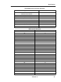
Before You Begin . . . . . . . . . . . . . . . . . . . . . . . . . . . . . . . . . . . . . . . . . . . . . . . . . . . . . . . . . . . . .
Printing the Hardware User Guide . . . . . . . . . . . . . . . . . . . . . . . . . . . . . . . . . . . . . . . . . . . . .
What's New in this Release? . . . . . . . . . . . . . . . . . . . . . . . . . . . . . . . . . . . . . . . . . . . . . . . . .
Disclaimer . . . . . . . . . . . . . . . . . . . . . . . . . . . . . . . . . . . . . . . . . . . . . . . . . . . . . . . . . . . . . . .
Trademarks . . . . . . . . . . . . . . . . . . . . . . . . . . . . . . . . . . . . . . . . . . . . . . . . . . . . . . . . . . . . . .
Copyright . . . . . . . . . . . . . . . . . . . . . . . . . . . . . . . . . . . . . . . . . . . . . . . . . . . . . . . . . . . . . . . .
Safety Instructions . . . . . . . . . . . . . . . . . . . . . . . . . . . . . . . . . . . . . . . . . . . . . . . . . . . . . . . . .
3
3
3
4
4
4
5
Chapter 2 - Specifications
Specifications . . . . . . . . . . . . . . . . . . . . . . . . . . . . . . . . . . . . . . . . . . . . . . . . . . . . . . . . . . . . . . . . 9
Technical Information . . . . . . . . . . . . . . . . . . . . . . . . . . . . . . . . . . . . . . . . . . . . . . . . . . . . . . 9
Technical Characteristics . . . . . . . . . . . . . . . . . . . . . . . . . . . . . . . . . . . . . . . . . . . . . . . . . 9
Transmission Characteristics . . . . . . . . . . . . . . . . . . . . . . . . . . . . . . . . . . . . . . . . . . . . . 11
Loss and Level Matrices . . . . . . . . . . . . . . . . . . . . . . . . . . . . . . . . . . . . . . . . . . . . . . . . . 11
Tone Plans . . . . . . . . . . . . . . . . . . . . . . . . . . . . . . . . . . . . . . . . . . . . . . . . . . . . . . . . . . . 19
E2T Compression . . . . . . . . . . . . . . . . . . . . . . . . . . . . . . . . . . . . . . . . . . . . . . . . . . . . . . 35
3300 Controller . . . . . . . . . . . . . . . . . . . . . . . . . . . . . . . . . . . . . . . . . . . . . . . . . . . . . . . . . . 38
100 Controller . . . . . . . . . . . . . . . . . . . . . . . . . . . . . . . . . . . . . . . . . . . . . . . . . . . . . . . . . 38
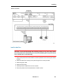
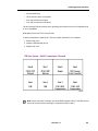
Mitel Networks™ 3300 - 100 Controller Components . . . . . . . . . . . . . . . . . . . . . . . . . . 38
Configurations . . . . . . . . . . . . . . . . . . . . . . . . . . . . . . . . . . . . . . . . . . . . . . . . . . . . . . . . 39
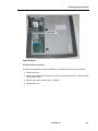
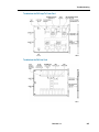
100 User System without Compression . . . . . . . . . . . . . . . . . . . . . . . . . . . . . . . . . . . . . 40
100 User System with 32 Compression Channels . . . . . . . . . . . . . . . . . . . . . . . . . . . . . 41
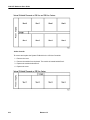
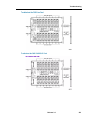
100 User System with 30 Voice Mail Ports . . . . . . . . . . . . . . . . . . . . . . . . . . . . . . . . . . . 42
100 User System with 32 Compression Channels and 30 Voice Mail Ports . . . . . . . . . 43
3300 Controller . . . . . . . . . . . . . . . . . . . . . . . . . . . . . . . . . . . . . . . . . . . . . . . . . . . . . . . . . . 44
250 and 700 Controller . . . . . . . . . . . . . . . . . . . . . . . . . . . . . . . . . . . . . . . . . . . . . . . . . . 44
Mitel Networks™ 3300 - 250 and 700 Controller Components . . . . . . . . . . . . . . . . . . . 44
Configurations . . . . . . . . . . . . . . . . . . . . . . . . . . . . . . . . . . . . . . . . . . . . . . . . . . . . . . . . 45
250 User System without Compression . . . . . . . . . . . . . . . . . . . . . . . . . . . . . . . . . . . . . 46
250 User System with 30 Voice Mail Ports . . . . . . . . . . . . . . . . . . . . . . . . . . . . . . . . . . . 47
250 User System with 32 Compression Channels . . . . . . . . . . . . . . . . . . . . . . . . . . . . . 48
250 User System with 32 Compression Channels and 30 Voice Mail Ports . . . . . . . . . 49
250 User System with 64 Compression Channels . . . . . . . . . . . . . . . . . . . . . . . . . . . . . 50
250 User System with 64 Compression Channels and 30 Voice Mail Ports . . . . . . . . . 51
700 User System without Compression . . . . . . . . . . . . . . . . . . . . . . . . . . . . . . . . . . . . . 52
700 User System with 32 Compression Channels . . . . . . . . . . . . . . . . . . . . . . . . . . . . . 53
700 User System with 64 Compression Channels . . . . . . . . . . . . . . . . . . . . . . . . . . . . . 54
Mitel Networks 3300 Controller Dimensions . . . . . . . . . . . . . . . . . . . . . . . . . . . . . . . . . . 55
3300 Controller Environment . . . . . . . . . . . . . . . . . . . . . . . . . . . . . . . . . . . . . . . . . . . . . 55
3300 Controller Power . . . . . . . . . . . . . . . . . . . . . . . . . . . . . . . . . . . . . . . . . . . . . . . . . . 55
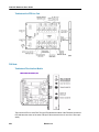
3300 Controller PCB Interfaces . . . . . . . . . . . . . . . . . . . . . . . . . . . . . . . . . . . . . . . . . . . 56
Release 3.3
iii
3300 ICP Hardware User Guide
3300 Network Services Units . . . . . . . . . . . . . . . . . . . . . . . . . . . . . . . . . . . . . . . . . . . . . . . . 57
Mitel Networks™ 3300 Universal NSU Components . . . . . . . . . . . . . . . . . . . . . . . . . . . 57
3300 Universal NSU Protocols . . . . . . . . . . . . . . . . . . . . . . . . . . . . . . . . . . . . . . . . . . . . 58
3300 Universal NSU DIP Switch Settings . . . . . . . . . . . . . . . . . . . . . . . . . . . . . . . . . . . . 58
Mitel Networks™ 3300 R2 NSU Components . . . . . . . . . . . . . . . . . . . . . . . . . . . . . . . . 59
3300 R2 NSU Protocols . . . . . . . . . . . . . . . . . . . . . . . . . . . . . . . . . . . . . . . . . . . . . . . . . 59
3300 R2 NSU DIP Switch Settings . . . . . . . . . . . . . . . . . . . . . . . . . . . . . . . . . . . . . . . . . 60
Mitel Networks™ 3300 BRI NSU Components . . . . . . . . . . . . . . . . . . . . . . . . . . . . . . . . 60
3300 BRI NSU Protocols . . . . . . . . . . . . . . . . . . . . . . . . . . . . . . . . . . . . . . . . . . . . . . . . 61
Mitel Networks 3300 NSU Dimensions . . . . . . . . . . . . . . . . . . . . . . . . . . . . . . . . . . . . . . 61
3300 NSU Environment . . . . . . . . . . . . . . . . . . . . . . . . . . . . . . . . . . . . . . . . . . . . . . . . . 61
3300 NSU Power . . . . . . . . . . . . . . . . . . . . . . . . . . . . . . . . . . . . . . . . . . . . . . . . . . . . . . 62
3300 NSU Pin Allocations . . . . . . . . . . . . . . . . . . . . . . . . . . . . . . . . . . . . . . . . . . . . . . . . 62
3300 Analog Services Units . . . . . . . . . . . . . . . . . . . . . . . . . . . . . . . . . . . . . . . . . . . . . . . . . 64
Mitel Networks™ 3300 Universal ASU Components . . . . . . . . . . . . . . . . . . . . . . . . . . . 64
Mitel Networks™ 3300 ASU Components . . . . . . . . . . . . . . . . . . . . . . . . . . . . . . . . . . . 64
3300 ASU and Universal ASU Dimensions . . . . . . . . . . . . . . . . . . . . . . . . . . . . . . . . . . 65
3300 ASU and Universal ASU Environment . . . . . . . . . . . . . . . . . . . . . . . . . . . . . . . . . . 65
3300 ASU and Universal ASU Power . . . . . . . . . . . . . . . . . . . . . . . . . . . . . . . . . . . . . . . 66
3300 ASU and Universal ASU Pin Allocations . . . . . . . . . . . . . . . . . . . . . . . . . . . . . . . . 66
ONS Line Specifications . . . . . . . . . . . . . . . . . . . . . . . . . . . . . . . . . . . . . . . . . . . . . . . . . 67
LS Trunk Specifications . . . . . . . . . . . . . . . . . . . . . . . . . . . . . . . . . . . . . . . . . . . . . . . . . 69
Music On Hold (3300 Universal ASU only) . . . . . . . . . . . . . . . . . . . . . . . . . . . . . . . . . . . 70
Paging (3300 Universal ASU only) . . . . . . . . . . . . . . . . . . . . . . . . . . . . . . . . . . . . . . . . . 71
System Fail Transfer (3300 Universal ASU only) . . . . . . . . . . . . . . . . . . . . . . . . . . . . . . 71
Peripheral Node . . . . . . . . . . . . . . . . . . . . . . . . . . . . . . . . . . . . . . . . . . . . . . . . . . . . . . . . . . 72
Peripheral Unit Components . . . . . . . . . . . . . . . . . . . . . . . . . . . . . . . . . . . . . . . . . . . . . . 72
Peripheral Unit Dimensions . . . . . . . . . . . . . . . . . . . . . . . . . . . . . . . . . . . . . . . . . . . . . . 74
Peripheral Unit Environment . . . . . . . . . . . . . . . . . . . . . . . . . . . . . . . . . . . . . . . . . . . . . . 74
Peripheral Unit Power . . . . . . . . . . . . . . . . . . . . . . . . . . . . . . . . . . . . . . . . . . . . . . . . . . . 75
Peripheral Unit Cards . . . . . . . . . . . . . . . . . . . . . . . . . . . . . . . . . . . . . . . . . . . . . . . . . . . 75
SUPERSET HUB . . . . . . . . . . . . . . . . . . . . . . . . . . . . . . . . . . . . . . . . . . . . . . . . . . . . . . . . . 86
Digital Service Unit . . . . . . . . . . . . . . . . . . . . . . . . . . . . . . . . . . . . . . . . . . . . . . . . . . . . . . . . 88
Digital Service Unit Components . . . . . . . . . . . . . . . . . . . . . . . . . . . . . . . . . . . . . . . . . . 88
Digital Service Unit Dimensions . . . . . . . . . . . . . . . . . . . . . . . . . . . . . . . . . . . . . . . . . . . 89
Digital Service Unit Environment . . . . . . . . . . . . . . . . . . . . . . . . . . . . . . . . . . . . . . . . . . 89
Digital Service Unit Power . . . . . . . . . . . . . . . . . . . . . . . . . . . . . . . . . . . . . . . . . . . . . . . 90
Digital Service Unit Cards . . . . . . . . . . . . . . . . . . . . . . . . . . . . . . . . . . . . . . . . . . . . . . . . 91
Telephone Power Options . . . . . . . . . . . . . . . . . . . . . . . . . . . . . . . . . . . . . . . . . . . . . . . . . 104
Telephone Power Sources . . . . . . . . . . . . . . . . . . . . . . . . . . . . . . . . . . . . . . . . . . . . . . 104
3300 Power Dongle (Cisco compliant) . . . . . . . . . . . . . . . . . . . . . . . . . . . . . . . . . . . . . 104
PowerDsine In-line Power Unit . . . . . . . . . . . . . . . . . . . . . . . . . . . . . . . . . . . . . . . . . . . 105
iv
Release 3.3
Table of Contents
Chapter 3 - Installing
Installing . . . . . . . . . . . . . . . . . . . . . . . . . . . . . . . . . . . . . . . . . . . . . . . . . . . . . . . . . . . . . . . . . .
Required Components . . . . . . . . . . . . . . . . . . . . . . . . . . . . . . . . . . . . . . . . . . . . . . . . . . . .
Installation Site . . . . . . . . . . . . . . . . . . . . . . . . . . . . . . . . . . . . . . . . . . . . . . . . . . . . . . .
Parts and Equipment . . . . . . . . . . . . . . . . . . . . . . . . . . . . . . . . . . . . . . . . . . . . . . . . . .
Information and Services . . . . . . . . . . . . . . . . . . . . . . . . . . . . . . . . . . . . . . . . . . . . . . .
Power . . . . . . . . . . . . . . . . . . . . . . . . . . . . . . . . . . . . . . . . . . . . . . . . . . . . . . . . . . . . . .
Uninterruptible Power Supply . . . . . . . . . . . . . . . . . . . . . . . . . . . . . . . . . . . . . . . . . . . .
System Installation Overview . . . . . . . . . . . . . . . . . . . . . . . . . . . . . . . . . . . . . . . . . . . . . . .
Installation Planner . . . . . . . . . . . . . . . . . . . . . . . . . . . . . . . . . . . . . . . . . . . . . . . . . . . . . .
Capacity . . . . . . . . . . . . . . . . . . . . . . . . . . . . . . . . . . . . . . . . . . . . . . . . . . . . . . . . . . . . .
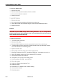
Install the 3300 Controller . . . . . . . . . . . . . . . . . . . . . . . . . . . . . . . . . . . . . . . . . . . . . . . . .
Install the Hard Drive . . . . . . . . . . . . . . . . . . . . . . . . . . . . . . . . . . . . . . . . . . . . . . . . . . . . .
Install the System ID Module . . . . . . . . . . . . . . . . . . . . . . . . . . . . . . . . . . . . . . . . . . . . . . .
Install DSP Modules . . . . . . . . . . . . . . . . . . . . . . . . . . . . . . . . . . . . . . . . . . . . . . . . . . . . .
Configure the Controller . . . . . . . . . . . . . . . . . . . . . . . . . . . . . . . . . . . . . . . . . . . . . . . . . . .
Set the 3300 Controller IP Address . . . . . . . . . . . . . . . . . . . . . . . . . . . . . . . . . . . . . . . . . .
Install the 3300 Configuration Tool . . . . . . . . . . . . . . . . . . . . . . . . . . . . . . . . . . . . . . . . . .
Install and Configure the Java Plug-In . . . . . . . . . . . . . . . . . . . . . . . . . . . . . . . . . . . . .
Program FTP User Account and Password . . . . . . . . . . . . . . . . . . . . . . . . . . . . . . . . .
Assign Domain Account . . . . . . . . . . . . . . . . . . . . . . . . . . . . . . . . . . . . . . . . . . . . . . . .
Configure IIS 5 Settings . . . . . . . . . . . . . . . . . . . . . . . . . . . . . . . . . . . . . . . . . . . . . . . .
Install the 3300 Universal NSU . . . . . . . . . . . . . . . . . . . . . . . . . . . . . . . . . . . . . . . . . . . . .
Install the 3300 Universal NSU . . . . . . . . . . . . . . . . . . . . . . . . . . . . . . . . . . . . . . . . . . .
Install for PRI/Q.SIG . . . . . . . . . . . . . . . . . . . . . . . . . . . . . . . . . . . . . . . . . . . . . . . . . . .
Install Direct Connect Device Driver . . . . . . . . . . . . . . . . . . . . . . . . . . . . . . . . . . . . . . .
Driver for Windows 95 and Windows 98 . . . . . . . . . . . . . . . . . . . . . . . . . . . . . . . . . . . .
Driver for Windows 2000 . . . . . . . . . . . . . . . . . . . . . . . . . . . . . . . . . . . . . . . . . . . . . . .
Create a Dial-up Network Connection . . . . . . . . . . . . . . . . . . . . . . . . . . . . . . . . . . . . .
Dial-up Connection for Windows 95 or Windows 98 . . . . . . . . . . . . . . . . . . . . . . . . . . .
Dial-up Connection for Windows 2000 . . . . . . . . . . . . . . . . . . . . . . . . . . . . . . . . . . . . .
Install the 3300 R2 NSU . . . . . . . . . . . . . . . . . . . . . . . . . . . . . . . . . . . . . . . . . . . . . . . . . .
Connections . . . . . . . . . . . . . . . . . . . . . . . . . . . . . . . . . . . . . . . . . . . . . . . . . . . . . . . . .
Install the 3300 BRI NSU . . . . . . . . . . . . . . . . . . . . . . . . . . . . . . . . . . . . . . . . . . . . . . . . . .
Setting Up the Maintenance PC . . . . . . . . . . . . . . . . . . . . . . . . . . . . . . . . . . . . . . . . . .
NSU Chaining . . . . . . . . . . . . . . . . . . . . . . . . . . . . . . . . . . . . . . . . . . . . . . . . . . . . . . . . . .
Install the 3300 Universal ASU . . . . . . . . . . . . . . . . . . . . . . . . . . . . . . . . . . . . . . . . . . . . .
Install the 3300 ASU . . . . . . . . . . . . . . . . . . . . . . . . . . . . . . . . . . . . . . . . . . . . . . . . . . . . .
Install the Peripheral Unit . . . . . . . . . . . . . . . . . . . . . . . . . . . . . . . . . . . . . . . . . . . . . . . . . .
Overview of the Peripheral Unit Installation . . . . . . . . . . . . . . . . . . . . . . . . . . . . . . . . .
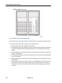
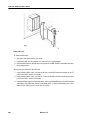
Unpack, Position, and Ground the Peripheral Unit . . . . . . . . . . . . . . . . . . . . . . . . . . . .
Peripheral Unit Card Layout . . . . . . . . . . . . . . . . . . . . . . . . . . . . . . . . . . . . . . . . . . . . .
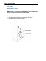
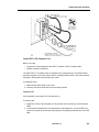
Connect Fiber Cable to the Peripheral Unit . . . . . . . . . . . . . . . . . . . . . . . . . . . . . . . . .
Peripheral Unit Grounding . . . . . . . . . . . . . . . . . . . . . . . . . . . . . . . . . . . . . . . . . . . . . .
Power Converter . . . . . . . . . . . . . . . . . . . . . . . . . . . . . . . . . . . . . . . . . . . . . . . . . . . . . .
Release 3.3
111
111
111
112
112
113
113
114
114
117
120
121
122
123
123
125
126
127
127
128
128
129
129
130
130
130
131
132
132
133
133
134
134
135
135
135
136
136
136
137
137
138
139
140
v
3300 ICP Hardware User Guide
Install Peripheral Interface Cards . . . . . . . . . . . . . . . . . . . . . . . . . . . . . . . . . . . . . . . . .
Cable the Unit to the MDF . . . . . . . . . . . . . . . . . . . . . . . . . . . . . . . . . . . . . . . . . . . . . .
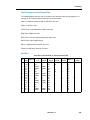
Peripheral Interface Cabling Tables . . . . . . . . . . . . . . . . . . . . . . . . . . . . . . . . . . . . . . .
USOC Connector Pin Designations . . . . . . . . . . . . . . . . . . . . . . . . . . . . . . . . . . . . . . .
Card Connections to Cross-Connect Field . . . . . . . . . . . . . . . . . . . . . . . . . . . . . . . . . .
Card Slot 1 . . . . . . . . . . . . . . . . . . . . . . . . . . . . . . . . . . . . . . . . . . . . . . . . . . . . . . . . . .
Card Slot 2 . . . . . . . . . . . . . . . . . . . . . . . . . . . . . . . . . . . . . . . . . . . . . . . . . . . . . . . . . .
Card Slot 3 . . . . . . . . . . . . . . . . . . . . . . . . . . . . . . . . . . . . . . . . . . . . . . . . . . . . . . . . . .
Card Slot 4 . . . . . . . . . . . . . . . . . . . . . . . . . . . . . . . . . . . . . . . . . . . . . . . . . . . . . . . . . .
Card Slot 5 . . . . . . . . . . . . . . . . . . . . . . . . . . . . . . . . . . . . . . . . . . . . . . . . . . . . . . . . . .
Card Slot 6 . . . . . . . . . . . . . . . . . . . . . . . . . . . . . . . . . . . . . . . . . . . . . . . . . . . . . . . . . .
Card Slot 7 . . . . . . . . . . . . . . . . . . . . . . . . . . . . . . . . . . . . . . . . . . . . . . . . . . . . . . . . . .
Card Slot 8 . . . . . . . . . . . . . . . . . . . . . . . . . . . . . . . . . . . . . . . . . . . . . . . . . . . . . . . . . .
Card Slot 9 . . . . . . . . . . . . . . . . . . . . . . . . . . . . . . . . . . . . . . . . . . . . . . . . . . . . . . . . . .
Card Slot 10 . . . . . . . . . . . . . . . . . . . . . . . . . . . . . . . . . . . . . . . . . . . . . . . . . . . . . . . . .
Card Slot 11 . . . . . . . . . . . . . . . . . . . . . . . . . . . . . . . . . . . . . . . . . . . . . . . . . . . . . . . . .
Card Slot 12 . . . . . . . . . . . . . . . . . . . . . . . . . . . . . . . . . . . . . . . . . . . . . . . . . . . . . . . . .
Install the SUPERSET HUB . . . . . . . . . . . . . . . . . . . . . . . . . . . . . . . . . . . . . . . . . . . . . . . .
Overview of the SUPERSET Hub Installation . . . . . . . . . . . . . . . . . . . . . . . . . . . . . . . .
Install the Peripheral Slot FIM Carrier . . . . . . . . . . . . . . . . . . . . . . . . . . . . . . . . . . . . . .
Install the SUPERSET HUB . . . . . . . . . . . . . . . . . . . . . . . . . . . . . . . . . . . . . . . . . . . . .
Install the Digital Service Unit . . . . . . . . . . . . . . . . . . . . . . . . . . . . . . . . . . . . . . . . . . . . . .
Overview of the Digital Service Unit Installation . . . . . . . . . . . . . . . . . . . . . . . . . . . . . .
Unpack, Position, and Ground the DSU . . . . . . . . . . . . . . . . . . . . . . . . . . . . . . . . . . . .
DSU Card Layout . . . . . . . . . . . . . . . . . . . . . . . . . . . . . . . . . . . . . . . . . . . . . . . . . . . . .
Connect Fiber Cable to the DSU . . . . . . . . . . . . . . . . . . . . . . . . . . . . . . . . . . . . . . . . .
Install DSU Cards . . . . . . . . . . . . . . . . . . . . . . . . . . . . . . . . . . . . . . . . . . . . . . . . . . . . .
Interface Assembly . . . . . . . . . . . . . . . . . . . . . . . . . . . . . . . . . . . . . . . . . . . . . . . . . . . .
DS1 Interface Assembly and Cabling . . . . . . . . . . . . . . . . . . . . . . . . . . . . . . . . . . . . . .
CEPT Interface Assembly and Cabling . . . . . . . . . . . . . . . . . . . . . . . . . . . . . . . . . . . .
Install Wireless Devices . . . . . . . . . . . . . . . . . . . . . . . . . . . . . . . . . . . . . . . . . . . . . . . . . . .
Install Symbol NetVision MiNET Phone Administrator Tool . . . . . . . . . . . . . . . . . . . . .
Install 3300 ICP as a Stand-alone IP Gateway . . . . . . . . . . . . . . . . . . . . . . . . . . . . . . . . .
Install 3300 ICP as a Stand-alone Voice Mail . . . . . . . . . . . . . . . . . . . . . . . . . . . . . . . . . .
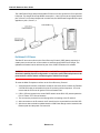
Install the 3300 In-Line Power Unit . . . . . . . . . . . . . . . . . . . . . . . . . . . . . . . . . . . . . . . . . .
Rack Mounting . . . . . . . . . . . . . . . . . . . . . . . . . . . . . . . . . . . . . . . . . . . . . . . . . . . . . . .
Shelf Mounting . . . . . . . . . . . . . . . . . . . . . . . . . . . . . . . . . . . . . . . . . . . . . . . . . . . . . . .
Powering Up . . . . . . . . . . . . . . . . . . . . . . . . . . . . . . . . . . . . . . . . . . . . . . . . . . . . . . . . .
Connecting Cables to the In-Line Power Unit . . . . . . . . . . . . . . . . . . . . . . . . . . . . . . . .
Connecting Cables to End Devices . . . . . . . . . . . . . . . . . . . . . . . . . . . . . . . . . . . . . . .
Install the 3300 In-Line Power Adapter . . . . . . . . . . . . . . . . . . . . . . . . . . . . . . . . . . . . . . .
Install 3300 Power Dongle (Cisco compliant) . . . . . . . . . . . . . . . . . . . . . . . . . . . . . . . . . .
Install 3300 Power Dongle (Cisco compliant) . . . . . . . . . . . . . . . . . . . . . . . . . . . . . . . .
Pre-Release 3.2 IP Phones . . . . . . . . . . . . . . . . . . . . . . . . . . . . . . . . . . . . . . . . . . . . .
Mixed Release 3.1 and 3.2 Network . . . . . . . . . . . . . . . . . . . . . . . . . . . . . . . . . . . . . . .
vi
Release 3.3
141
141
143
143
145
145
146
147
148
150
151
152
153
154
155
156
157
158
158
158
159
160
160
160
161
161
162
162
163
163
164
164
165
166
166
167
167
167
168
168
169
169
169
170
171
Table of Contents
Chapter 4 - Install Upgrades and FRUs
Install Upgrades and FRUs . . . . . . . . . . . . . . . . . . . . . . . . . . . . . . . . . . . . . . . . . . . . . . . . . . .
Hardware . . . . . . . . . . . . . . . . . . . . . . . . . . . . . . . . . . . . . . . . . . . . . . . . . . . . . . . . . . . . . .
Controller Upgrade Options . . . . . . . . . . . . . . . . . . . . . . . . . . . . . . . . . . . . . . . . . . . . .
100 User System - Add Voice Mail Ports . . . . . . . . . . . . . . . . . . . . . . . . . . . . . . . . . . .
100 User System - Add 32 Compression Channels . . . . . . . . . . . . . . . . . . . . . . . . . . .
100 User System - Add 32 Compression Channels and Voice Mail Ports . . . . . . . . . .
250 User System - Add Voice Mail Ports . . . . . . . . . . . . . . . . . . . . . . . . . . . . . . . . . . .
250 User System - Add 32 Compression Channels . . . . . . . . . . . . . . . . . . . . . . . . . . .
250 User System - Add 32 Compression Channels and Voice Mail Ports . . . . . . . . . .
250 User System - Add 64 Compression Channels . . . . . . . . . . . . . . . . . . . . . . . . . . .
250 User System - Add 64 Compression Channels and Voice Mail Ports . . . . . . . . . .
250 User to 700 User System - No Compression Channels . . . . . . . . . . . . . . . . . . . .
250 User to 700 User System - 32 Compression Channels . . . . . . . . . . . . . . . . . . . . .
250 User to 700 User System - 64 Compression Channels . . . . . . . . . . . . . . . . . . . . .
700 User System - Add 32 Compression Channels . . . . . . . . . . . . . . . . . . . . . . . . . . .
700 User System - Add 64 Compression Channels . . . . . . . . . . . . . . . . . . . . . . . . . . .
SX-2000 LIGHT to 3300 ICP . . . . . . . . . . . . . . . . . . . . . . . . . . . . . . . . . . . . . . . . . . . .
SX-2000 MICRO LIGHT to 3300 ICP . . . . . . . . . . . . . . . . . . . . . . . . . . . . . . . . . . . . . .
3200 ICP to 3300 ICP . . . . . . . . . . . . . . . . . . . . . . . . . . . . . . . . . . . . . . . . . . . . . . . . . .
Software . . . . . . . . . . . . . . . . . . . . . . . . . . . . . . . . . . . . . . . . . . . . . . . . . . . . . . . . . . . . . . .
Software Upgrade Procedure (3.2 to 3.3) . . . . . . . . . . . . . . . . . . . . . . . . . . . . . . . . . . .
Upgrade SX-2000 LIGHT to 3300 ICP Software . . . . . . . . . . . . . . . . . . . . . . . . . . . . .
Upgrade SX-2000 MICRO LIGHT to 3300 ICP Software . . . . . . . . . . . . . . . . . . . . . . .
Upgrade 3200 ICP to 3300 ICP Software . . . . . . . . . . . . . . . . . . . . . . . . . . . . . . . . . . .
Field Replaceable Units . . . . . . . . . . . . . . . . . . . . . . . . . . . . . . . . . . . . . . . . . . . . . . . .
Peripheral Node FRUs . . . . . . . . . . . . . . . . . . . . . . . . . . . . . . . . . . . . . . . . . . . . . . . . .
175
175
175
176
177
178
179
180
181
183
185
186
188
189
190
192
194
195
195
195
195
202
203
204
208
213
Chapter 5 - Programming
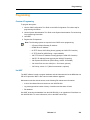
Programming . . . . . . . . . . . . . . . . . . . . . . . . . . . . . . . . . . . . . . . . . . . . . . . . . . . . . . . . . . . . . . 257
Overview of Programming . . . . . . . . . . . . . . . . . . . . . . . . . . . . . . . . . . . . . . . . . . . . . . . . . 257
Use IMAT . . . . . . . . . . . . . . . . . . . . . . . . . . . . . . . . . . . . . . . . . . . . . . . . . . . . . . . . . . . . . . 257
Chapter 6 - Troubleshooting
Troubleshooting . . . . . . . . . . . . . . . . . . . . . . . . . . . . . . . . . . . . . . . . . . . . . . . . . . . . . . . . . . . .
Hardware . . . . . . . . . . . . . . . . . . . . . . . . . . . . . . . . . . . . . . . . . . . . . . . . . . . . . . . . . . . . . .
Troubleshoot the 3300 Controller . . . . . . . . . . . . . . . . . . . . . . . . . . . . . . . . . . . . . . . . .
System Hardware Profile . . . . . . . . . . . . . . . . . . . . . . . . . . . . . . . . . . . . . . . . . . . . . . .
Troubleshoot the 3300 Universal NSU . . . . . . . . . . . . . . . . . . . . . . . . . . . . . . . . . . . . .
Troubleshoot the 3300 R2 NSU . . . . . . . . . . . . . . . . . . . . . . . . . . . . . . . . . . . . . . . . . .
Troubleshoot the 3300 BRI NSU . . . . . . . . . . . . . . . . . . . . . . . . . . . . . . . . . . . . . . . . .
Troubleshoot the 3300 Universal ASU . . . . . . . . . . . . . . . . . . . . . . . . . . . . . . . . . . . . .
Troubleshoot the 3300 ASU . . . . . . . . . . . . . . . . . . . . . . . . . . . . . . . . . . . . . . . . . . . . .
Troubleshoot the 3300 In-Line Power Unit . . . . . . . . . . . . . . . . . . . . . . . . . . . . . . . . . .
Release 3.3
233
233
233
234
234
236
237
237
238
238
vii
3300 ICP Hardware User Guide
Troubleshooting . . . . . . . . . . . . . . . . . . . . . . . . . . . . . . . . . . . . . . . . . . . . . . . . . . . . . . . . .
Peripheral Unit . . . . . . . . . . . . . . . . . . . . . . . . . . . . . . . . . . . . . . . . . . . . . . . . . . . . . . . . . .
Troubleshoot Fiber Interface Module . . . . . . . . . . . . . . . . . . . . . . . . . . . . . . . . . . . . . .
Troubleshoot the DID Loop/Tie Trunk Card . . . . . . . . . . . . . . . . . . . . . . . . . . . . . . . . .
Troubleshoot the DNI Line Card . . . . . . . . . . . . . . . . . . . . . . . . . . . . . . . . . . . . . . . . . .
Troubleshoot the DTMF Receiver Card . . . . . . . . . . . . . . . . . . . . . . . . . . . . . . . . . . . .
Troubleshoot E&M Trunk Card . . . . . . . . . . . . . . . . . . . . . . . . . . . . . . . . . . . . . . . . . . .
Troubleshoot LS/GS Trunk Card . . . . . . . . . . . . . . . . . . . . . . . . . . . . . . . . . . . . . . . . .
Troubleshoot the ONS Line Card . . . . . . . . . . . . . . . . . . . . . . . . . . . . . . . . . . . . . . . . .
Troubleshoot the ONS CLASS/CLIP Card . . . . . . . . . . . . . . . . . . . . . . . . . . . . . . . . . .
Troubleshoot the OPS Line Card . . . . . . . . . . . . . . . . . . . . . . . . . . . . . . . . . . . . . . . . .
DSU Node . . . . . . . . . . . . . . . . . . . . . . . . . . . . . . . . . . . . . . . . . . . . . . . . . . . . . . . . . . . . .
Troubleshoot Fiber Interface Module . . . . . . . . . . . . . . . . . . . . . . . . . . . . . . . . . . . . . .
Troubleshoot the BRI Card . . . . . . . . . . . . . . . . . . . . . . . . . . . . . . . . . . . . . . . . . . . . . .
Troubleshoot the CEPT/DS1 Formatter Card . . . . . . . . . . . . . . . . . . . . . . . . . . . . . . . .
Troubleshoot the Conference Card . . . . . . . . . . . . . . . . . . . . . . . . . . . . . . . . . . . . . . .
Troubleshoot the PRI Card . . . . . . . . . . . . . . . . . . . . . . . . . . . . . . . . . . . . . . . . . . . . . .
Troubleshoot the R2 Card . . . . . . . . . . . . . . . . . . . . . . . . . . . . . . . . . . . . . . . . . . . . . .
Other . . . . . . . . . . . . . . . . . . . . . . . . . . . . . . . . . . . . . . . . . . . . . . . . . . . . . . . . . . . . . . . . .
Troubleshooting . . . . . . . . . . . . . . . . . . . . . . . . . . . . . . . . . . . . . . . . . . . . . . . . . . . . . .
viii
Release 3.3
239
242
242
243
243
244
244
245
247
247
248
248
248
249
250
250
251
252
253
253
Chapter 1
Before You Begin
3300 ICP Hardware User Guide
2
Release 3.3
Before You Begin
Before You Begin
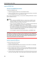
Printing the Hardware User Guide
You can access a printable version of the Hardware User Guide from the System Administration
Tool Help and from our web site.
Note: You must have Adobe Acrobat® Reader to view and print the Hardware User Guide.
If you need a copy of Adobe Acrobat Reader, it is available for download at
http://www.adobe.com/acrobat.
Go to section What's New in this Release? to find a list of changes to software and hardware
from one product version to the next.
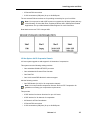
What's New in this Release?
3300 ICP Release 3.3:
•
New 3300 - 100 user chassis and configurations
•
Geographic expansion. See Loss Level and Tone Plans
•
Updates to IP-TDM G.729 compression
•
Upgrading 250/700 User systems to 30 Voice Mail ports
•
New Software Upgrade procedure.
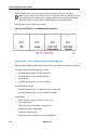
3300 ICP Release 3.2:
•
Single software build: select your country to set the appropriate language, dialing plan,
tone plan, and loss & level plan.
•
IP-TDM (E2T) G.729 compression
•
Optimized system performance: 300 MHz E2T and RTC
•
Symbol wireless telephones
•
3300 ICP as a Stand-alone Wireless Gateway
•
3300 ICP as a Stand-alone Voice Mail
•
Range programming to simplify the addition, change, or deletion of repetitive or
incremental values
•
Telephone power options
•
Personal and Corporate Directories on the 5140 IP Appliance
•
System Hardware Profile to view information about installed hardware
•
Controller upgrade options for capacity, version, and/or compression
•
ASU and Universal ASU to support the European market
Release 3.3
3
3300 ICP Hardware User Guide
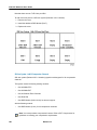
3300 ICP Release 3.1:
•
Migration of SX-2000® LIGHT to 3300 ICP
•
Migration of SX-2000 MICRO LIGHT to 3300 ICP
•
Migration of 3200 ICP to 3300 ICP
•
Peripheral Node support
•
Digital Service Unit support
•
NSU Chaining
•
5001 IP Phone and 5005 IP Phone
•
Security
Disclaimer
The information contained in this document is believed to be accurate in all respects but is not
warranted by Mitel Networks Corporation (MITEL®). The information is subject to change
without notice and should not be construed in any way as a commitment by Mitel or any of its
affiliates or subsidiaries. Mitel and its affiliates and subsidiaries assume no responsibility for
any errors or omissions in this document. Revisions of this document or new editions of it may
be issued to incorporate such changes.
Trademarks
Mitel Networks, MiTAI, SUPERSET, SX-2000 are trademarks of Mitel Networks Corporation.
Windows and Microsoft are trademarks of Microsoft Corporation.
Java is a trademark of Sun Microsystems Incorporated.
Adobe Acrobat Reader is a registered trademark of Adobe Systems Incorporated.
Other product names mentioned in this document may be trademarks of their respective
companies and are hereby acknowledged.
Copyright
®,™ Trademark of MITEL Networks Corporation
© Copyright 2002, MITEL Networks Corporation
All rights reserved
4
Release 3.3
Before You Begin
Safety Instructions
You can access a printable version of the Safety Instructions from our edocs web site.
Note: You must have Adobe Acrobat® Reader to view and print the Safety Instructions.
If you need a copy of Adobe Acrobat® Reader, it is available for download at
http://www.adobe.com/acrobat.
Release 3.3
5
3300 ICP Hardware User Guide
6
Release 3.3
Chapter 2
Specifications
3300 ICP Hardware User Guide
8
Release 3.3
Specifications
Specifications
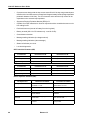
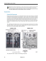
Technical Information
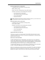
Technical Characteristics
Signaling and Supervisory Tones
The standard range of programmed tones are composed of
•
12 DTMF sets of tones
•
1 set of tones that form part of the call progress tone plan
•
1 test of 1004 Hz (digital milliwatt).
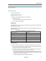
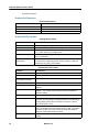
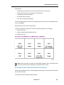
DTMF Signaling
Input Signaling: The system is capable of accepting and repeating the standard DTMF tones
as specified in EIA/TIA 464-C.
Output Signaling: The Mitel Networks 3300 ICP meets the output signaling requirements as
specified in EIA/TIA 464-C.
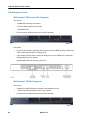
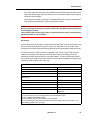
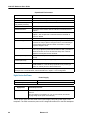
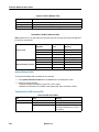
DTMF Output Signaling as specified by EIA/TIA 464-C
frequency deviation
1 percent
tone duration
greater than 40 ms
interdigit time
greater than 40 ms
level, low group
greater than -10 dbm
level, high group
greater than -8 dbm
level, low group and high group combined
less than +2 db
level, third
greater than 40 db
frequency
below dtmf signal
twist
less than 4 db
Time-Out Information
The system is capable of responding to, or providing, the following supervisory conditions:
•
Switchhook flashes having a duration of between 160 ms and 1500 ms (as programmed)
to activate Transfer/Consultation/Hold/Add-On features.
•
Call transfer dial tone can be obtained by generating a calibrated flash. This method is
recognized internationally and is generated in one of three ways:
-
use a flash-hook for telephones connected to ONS circuits. Upper and lower detection
thresholds for switchhook flash are programmable between 60 ms and 500 ms, and
between 60 ms and 1500 ms respectively.
-
use the calibrated flash button (for equipped telephones)
Release 3.3
9
3300 ICP Hardware User Guide
-
dial the digit ‘1’ on an ordinary rotary telephone.
•
Station switchhook flashes of less than the maximum programmed switchhook flash time
will not be repeated towards the central office.
•
An open Tip lead condition of 500 ms (optional 100 ms) or more duration on a CO trunk
will release the system connection.
•
Momentary open loop conditions of up to 350 ms (optional 100 ms) generated by the
central office on outgoing system calls will not release calls.
•
Station on-hook conditions will release a trunk connection after the selected maximum
time.
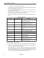
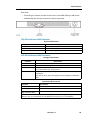
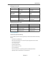
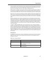
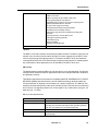
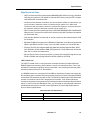
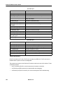
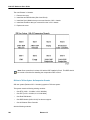
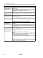
Time-Out Information
Feature
Time-Out Period
Description
No Answer Recall
Timer
0 - 125 s
If there is no answer at the extension after
time-out expires, it will ringback at the attendant
console or transfer station.
Camp-On Recall Timer
0 - 180 s
Incoming calls camped-on to a busy station
before being returned to the attendant, if not
answered before time-out expires.
Call Hold Timer
10 - 600 s
Calls placed on hold ring back to the station user
upon expiry.
Attendant Busyout
Timer
1 - 1440 min
System switches to night service if there is no
activity at the attendant console after calls are
received.
First Digit Timer
5 - 60 s
This is the time the system will wait for the first
digit after going offhook at a station.
Interdigit Timer
3 - 60 s
Time between dialed digits.
Delay Ring Timer
5 - 60 s
Time before line rings on key set.
Callback Cancel Timer
1 - 24 hrs
Time after which callback functions are reset and
cleared, or cancelled.
Call Forward - No
Answer Timer
0 - 125 s
Length of time a station rings before the call is
forwarded or rerouted.
Switchhook Flash
60 - 1500 ms
Length of time that a switchhook can be flashed
without dropping the trunk or line.
Ringing Timer
60 - 300 s
The length of time a station rings another station
before the call is terminated.
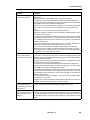
Line and Trunk Support Characteristics (NA)
The North American variant of the system supports the following line and trunk parameters:
10
•
Station Loop - The industry standard station loop range, including the station apparatus,
can be up to a maximum of 600 ohms (ONS Line).
•
DNI Device Ranges - Any device which interfaces to a DNI line card has a loop length of
2 kilometers (6600 ft) with 24 (0.6mm) or 26 (0.45mm) AWG twisted pair cable with no
bridge taps, and one kilometre with a maximum of one bridge tap of any length. A maximum
of 50 m (162.5 ft) of 22 AWG (0.7mm) quad cable may also be used.
Release 3.3
Specifications
•
CO Trunk Loop - The system operates with CO Trunks up to a maximum of 1600 ohms
loop resistance.
•
CO Trunk Seizure - The nominal seizure resistance is 265 ohms at 20 mA.
•
CO Trunk Resistance - The on-hook dc input resistance of the LS trunks is not less than
5M ohms.
Transmission Characteristics
Compliance
The transmission characteristics for the North American and Latin American variants comply
with:
•
ANSI/EIA/TIA 464-C 'Requirements for Private Branch Exchange (PBX) Switching
Equipment'.
•
TIA-912 'Voice Gateway Transmission Requirements'.
The transmission characteristics for the United Kingdom variants comply with:
•
ETSI ES 202 020 'Harmonized Pan-European/North American loss and level plan for voice
gateways to IP based networks'.
Mitel Networks digital telephones meet the requirements of:
•
ANSI/TIA/EIA-810-A 'Transmission Requirements for Narrowband Voice over IP and Voice
over PCM Digital Wireline Telephones'.
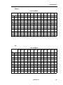
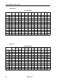
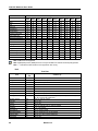
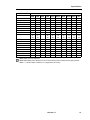
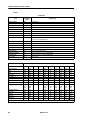
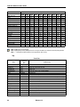
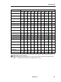
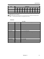
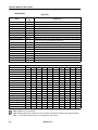
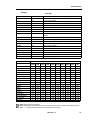
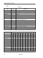
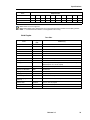
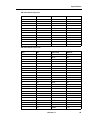
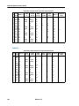
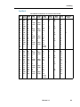
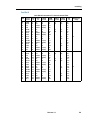
Loss and Level Matrices
Requirements Specifications
Each country has stipulated requirements concerning acceptable transmission performance
for telephone systems. The loss plan matrices provide the correct electrical losses in decibels
(dB) for each connection to meet the specified requirement.
Loss plans have a direct effect on the acoustic levels provided at the set. Part of meeting the
requirements is to identify the reference set requirements for all standard and proprietary sets
to be used in each country. It is generally desirable to achieve the same relative loudness levels
for all standard and proprietary telephones for a specified loss plan, taking into account loop
lengths, transmission format (analog or digital), different transducers in use, line/trunk
impedances, and terminating impedances.
Release 3.3
11
3300 ICP Hardware User Guide
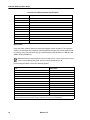
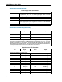
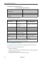
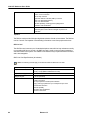
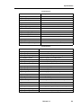
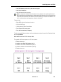
Loss and Level Requirements Specifications
Country
Requirement Document
Australia
ACIF S002, S003
Canada
CS03, T520, T512
France
TBR21, ST13
Germany
TBR21
Italy
TBR21
Netherlands
TBR21
New Zealand
TNA-102, PTC-207, PTC-217
North America
TIA/EIA 464-C, TIA/EIA TSB 116
Portugal
TBR21
Spain
TBR21
United Kingdom
BTR1050, BTR1080, BTR 1181, NCOP(86)42 and BS6450 Pt 4
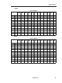
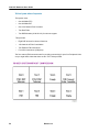
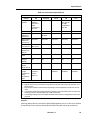
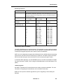
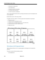
Implementation
In the loss plans, positive values are losses and negative values are gains. The losses are
shown in one direction only (outgoing, from the specified port type); the reverse path loss can
be found by using a second look up (e.g. In North America, OPS to WAN is a -3dB gain and
WAN to OPS is a 9dB loss).
Note: Mitel Networks digital telephones meet the following ITU-T recommended loudness rating:
- Send Loudness Rating (SLR) 8 dB - Receive Loudness Rating (RLR) 2 dB.
In interpreting loss plans, refer to the following legend:
Port
Abbreviation
IP On Premise Station
iONS
On Premise Station
ONS
IP Off Premise Station
iOPS
Off Premise Station
OPS
Digital Station
DGS
Wide Area Network
WAN
Digital CO Trunk
DCO
IP Analog CO Trunk
iACO
IP Analog CO Trunk (short)
iACOs
Analog CO Trunk
ACO
Analog CO Trunk (short)
ACOs
Analog Tie Trunk
ATT
Note: iONS, iACO, and iACOs apply to the new analog interface designs that comply with the IP
connected half-channel loss plan. The first instances of these is on the 3300 ASU.
12
Release 3.3
Specifications
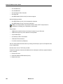
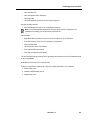
Australia
Loss Plan Matrix
iONS
→
iONS
↑
11
ONS
↑
11
iOPS
↑
8
OPS
↑
8
DGS
↑
3
WAN
↑
3
DCO
↑
2
ONS
→
11
11
8
8
3
3
2
0
1
1
1
2
iOPS
→
8
8
5
5
0
0
-1
-2
-2
-1
-1
-1
OPS
→
8
8
5
5
0
0
-1
-2
-2
-1
-1
-1
DGS
→
8
8
5
5
0
0
0
-1
2
0
3
0
WAN
→
8
8
5
5
0
0
0
-1
2
0
3
0
DCO
→
8
8
5
5
0
0
0
-1
0
0
0
0
iACO
→
0
0
-3
-3
-6
-5
-6
-4
-4
-4
-4
-6
iACOs
→
1
1
-2
-2
-6
-6
-6
-4
-4
-4
-4
-6
ACO
→
0
0
-3
-3
-6
-6
-6
-4
-4
-4
-4
-6
ACOs
→
1
1
-2
-2
-6
-6
-6
-4
-4
-4
-4
-6
ATT
→
7
7
4
4
0
0
0
0
0
0
0
0
iACO iACOs ACO ACOs
↑
↑
↑
↑
0
1
1
1
ATT
↑
2
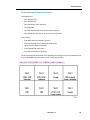
Brazil
Loss Plan Matrix
iONS
→
iONS
↑
6
ONS
↑
6
iOPS
↑
3
OPS
↑
3
DGS
↑
0
WAN
↑
0
DCO
↑
3
ONS
→
6
6
3
3
0
0
3
0
3
0
3
3
iOPS
→
3
3
0
0
-3
-3
0
0
0
0
0
3
OPS
→
3
3
0
0
-3
-3
0
0
0
0
0
3
DGS
→
9
9
6
6
0
0
0
2
3
0
3
3
WAN
→
9
9
6
6
0
0
0
3
0
3
0
3
DCO
→
9
9
6
6
0
0
0
3
0
3
0
3
iACO
→
0
0
0
0
-9
-6
-3
0
0
0
0
0
iACOs
→
3
3
0
0
-6
-3
-3
0
0
0
0
0
ACO
→
0
0
0
0
-9
-3
-3
0
0
0
0
0
ACOs
→
3
3
0
0
-6
0
0
0
0
0
0
0
ATT
→
3
3
0
0
-3
-3
-3
0
0
0
0
0
Release 3.3
iACO iACOs ACO ACOs
↑
↑
↑
↑
0
3
0
3
ATT
↑
3
13
3300 ICP Hardware User Guide
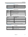
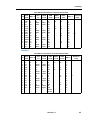
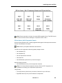
France
Loss Plan Matrix
iONS
→
iONS
↑
15
ONS
→
15
15
12
10
3
3
3
1
4
1
4
4
iOPS
→
12
12
9
9
2
2
1
-1
2
-1
2
2
OPS
→
12
12
9
7
0
0
0
-2
1
-2
1
1
DGS
→
10
10
7
7
0
0
0
0
2
0
2
4
WAN
→
10
10
7
7
0
0
0
0
2
0
2
4
DCO
→
11
11
8
7
0
0
0
0
2
0
2
4
iACO
→
1
1
-2
-2
-6
-6
-6
-6
-4
-6
-4
-2
iACOs
→
4
4
1
1
-3
-3
-3
-4
-2
-4
-2
1
ACO
→
1
1
-2
-2
-6
-6
-6
-6
-4
-6
-4
-2
ACOs
→
2
2
-1
-1
-5
-5
-5
-5
-3
-5
-3
-1
ATT
→
4
4
1
1
-3
-3
-3
-2
1
-2
1
1
14
ONS
↑
15
iOPS
↑
12
OPS
↑
12
DGS
↑
5
WAN
↑
5
DCO
↑
4
Release 3.3
iACO iACOs ACO ACOs
↑
↑
↑
↑
2
5
2
5
ATT
↑
5
Specifications
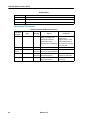
Germany
Loss Plan Matrix
iONS
→
iONS
↑
13
ONS
↑
13
iOPS
↑
10
OPS
↑
10
DGS
↑
4
WAN
↑
4
DCO
↑
4
ONS
→
13
13
10
10
3
3
3
0
2
1
3
3
iOPS
→
10
10
7
7
1
1
1
-1
-1
0
0
0
OPS
→
10
10
7
7
0
0
0
-1
1
0
0
0
DGS
→
10
10
7
7
0
0
0
-1
1
0
0
0
WAN
→
10
10
7
7
0
0
0
-1
1
0
0
0
DCO
→
10
10
7
7
0
0
0
-1
1
0
2
1
iACO
→
2
2
-1
0
-6
-6
-6
-7
-5
-6
-6
-6
iACOs
→
4
4
1
1
-6
-6
-6
-7
-5
-6
-6
-6
ACO
→
2
2
-1
0
-6
-6
-6
-7
-5
-6
-6
-6
ACOs
→
4
4
1
1
-6
-6
-6
-7
-5
-6
-4
-5
ATT
→
8
8
5
5
-2
-2
-2
-3
-1
-2
0
-1
ACOs
↑
6
ATT
↑
5
iACO iACOs ACO
↑
↑
↑
2
2
3
ACOs
↑
3
ATT
↑
3
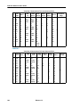
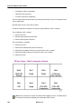
Italy
Loss Plan Matrix
iONS
→
iONS
↑
19
ONS
↑
17
iOPS
↑
16
OPS
↑
16
DGS
↑
7
WAN
↑
7
DCO
↑
7
ONS
→
17
13
14
12
3
3
3
6
6
6
6
7
iOPS
→
16
14
13
13
4
4
4
3
3
3
3
6
OPS
→
16
12
13
11
2
2
2
1
3
3
3
6
DGS
→
12
10
7
9
0
0
0
-1
-1
-1
-1
2
WAN
→
12
10
7
9
0
0
0
-1
-1
-1
-1
2
DCO
→
14
10
10
9
0
0
0
-1
2
2
2
4
iACO
→
4
4
-1
1
-6
-6
-6
-7
-7
-7
-7
-4
iACOs
→
4
4
1
1
-6
-6
-6
-7
-7
-7
-7
-4
ACO
→
5
4
2
1
-2
-2
-2
-3
-3
-5
-5
-4
ACOs
→
5
4
2
1
-2
-2
-2
-3
-3
-5
-5
-4
ATT
→
10
10
7
7
0
0
0
-1
-1
-1
-1
2
Release 3.3
iACO iACOs ACO
↑
↑
↑
6
6
6
15
3300 ICP Hardware User Guide
Latin America
Loss Plan Matrix
iONS
→
iONS
↑
6
ONS
↑
6
iOPS
↑
3
OPS
↑
3
DGS
↑
0
WAN
↑
0
DCO
↑
3
ONS
→
6
6
3
3
0
0
3
0
3
0
3
3
iOPS
→
3
3
0
0
-3
-3
0
0
0
0
0
3
OPS
→
3
3
0
0
-3
-3
0
0
0
0
0
3
DGS
→
9
9
6
6
0
0
0
2
3
0
3
3
WAN
→
9
9
6
6
0
0
0
3
0
3
0
3
DCO
→
9
9
6
6
0
0
0
3
0
3
0
3
iACO
→
0
0
0
0
-9
-6
-3
0
0
0
0
0
iACOs
→
3
3
0
0
-6
-3
-3
0
0
0
0
0
ACO
→
0
0
0
0
-9
-3
-3
0
0
0
0
0
ACOs
→
3
3
0
0
-6
0
0
0
0
0
0
0
ATT
→
3
3
0
0
-3
-3
-3
0
0
0
0
0
ACOs
↑
1
ATT
↑
1
iACO iACOs ACO
↑
↑
↑
0
3
0
ACOs
↑
3
ATT
↑
3
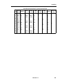
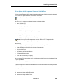
Netherlands
Loss Plan Matrix
iONS
→
iONS
↑
10
ONS
→
10
10
7
7
3
3
3
2
3
3
3
3
iOPS
→
7
7
4
4
-2
-2
-2
-2
-2
-2
-2
-2
OPS
→
7
7
4
4
0
0
0
-1
0
0
0
0
DGS
→
7
7
4
4
0
0
0
-1
0
0
0
0
WAN
→
7
7
4
4
0
0
0
-1
0
0
0
0
DCO
→
7
7
4
4
0
0
0
-1
0
0
0
0
iACO
→
1
1
-2
-2
-6
-6
-6
-7
-6
-6
-6
-6
iACOs
→
1
1
-2
-2
-6
-6
-6
-7
-5
-6
-6
-5
ACO
→
1
1
-2
-2
-6
-6
-6
-7
-6
-6
-6
-6
ACOs
→
1
1
-2
-2
-6
-6
-6
-7
-6
-6
-6
-5
ATT
→
5
5
2
2
-2
-2
-2
-2
0
-2
-2
0
16
ONS
↑
10
iOPS
↑
7
OPS
↑
7
DGS
↑
1
WAN
↑
1
DCO
↑
1
Release 3.3
iACO iACOs ACO
↑
↑
↑
1
1
1
Specifications
New Zealand
Loss Plan Matrix
iONS
→
iONS
↑
11
ONS
↑
11
iOPS
↑
8
OPS
↑
8
DGS
↑
3
WAN
↑
3
DCO
↑
3
ONS
→
11
11
8
8
3
3
3
0
2
0
2
-1
iOPS
→
8
8
5
5
0
0
0
-3
-1
-3
-1
-4
OPS
→
8
8
5
5
0
0
0
-3
-1
-3
-1
-4
DGS
→
8
8
5
5
0
0
0
-2
0
-2
0
-2
WAN
→
8
8
5
5
0
0
0
-2
0
-2
0
-2
DCO
→
8
8
5
5
0
0
0
-2
0
-2
0
-1
iACO
→
0
0
-3
-3
-8
-8
-8
-8
-8
-8
-8
-9
iACOs
→
2
2
-1
-1
-6
-6
-6
-8
-6
-8
-6
-8
ACO
→
0
0
-3
-1
-3
-3
-3
-5
-5
-6
-6
-6
ACOs
→
2
2
-1
-1
-3
-3
-3
-5
-5
-6
-6
-6
ATT
→
10
10
7
7
4
4
4
2
3
5
5
2
iACO iACOs ACO
↑
↑
↑
0
2
0
ACOs
↑
2
ATT
↑
-1
North America
Loss Plan Matrix
iONS
→
iONS
↑
6
ONS
↑
6
iOPS
↑
3
OPS
↑
3
DGS
↑
0
WAN
↑
0
DCO
↑
3
ONS
→
6
6
3
3
0
0
3
0
3
0
3
3
iOPS
→
3
3
0
0
-3
-3
0
0
0
0
0
3
OPS
→
3
3
0
0
-3
-3
0
0
0
0
0
3
DGS
→
9
9
6
6
0
0
0
2
3
0
3
3
WAN
→
9
9
6
6
0
0
0
3
0
3
0
3
DCO
→
9
9
6
6
0
0
0
3
0
3
0
3
iACO
→
0
0
0
0
-9
-6
-3
0
0
0
0
0
iACOs
→
3
3
0
0
-6
-3
-3
0
0
0
0
0
ACO
→
0
0
0
0
-9
-3
-3
0
0
0
0
0
ACOs
→
3
3
0
0
-6
0
0
0
0
0
0
0
ATT
→
3
3
0
0
-3
-3
-3
0
0
0
0
0
Release 3.3
iACO iACOs ACO ACOs
↑
↑
↑
↑
0
3
0
3
ATT
↑
3
17
3300 ICP Hardware User Guide
Portugal
Loss Plan Matrix
iONS
→
iONS
↑
15
ONS
↑
15
iOPS
↑
12
OPS
↑
12
DGS
↑
5
WAN
↑
5
DCO
↑
5
ONS
→
13
13
10
10
3
3
3
2
4
3
5
5
iOPS
→
12
12
9
9
2
2
2
-1
1
0
2
2
OPS
→
10
10
7
7
0
0
0
-1
1
0
2
2
DGS
→
10
10
7
7
0
0
0
-1
1
0
0
0
WAN
→
10
10
7
7
0
0
0
-1
1
0
0
0
DCO
→
10
10
7
7
0
0
0
-1
1
0
2
1
iACO
→
2
2
-1
0
-6
-6
-6
-7
-5
-6
-6
-6
iACOs
→
4
4
1
1
-6
-6
-6
-7
-5
-6
-6
-6
ACO
→
2
2
-1
0
-6
-6
-6
-7
-5
-6
-6
-6
ACOs
→
4
4
1
1
-6
-6
-6
-7
-5
-6
-4
-4
ATT
→
6
6
3
3
-4
-4
-4
-5
-3
-4
-2
-2
iACO iACOs ACO ACOs
↑
↑
↑
↑
2
4
3
5
ATT
↑
5
Spain
Loss Plan Matrix
iONS
→
iONS
↑
15
ONS
→
13
13
10
10
3
3
3
2
4
3
5
5
iOPS
→
12
12
9
9
2
2
2
-1
1
0
2
2
OPS
→
10
10
7
7
0
0
0
-1
1
0
2
2
DGS
→
10
10
7
7
0
0
0
-1
1
0
0
0
WAN
→
10
10
7
7
0
0
0
-1
1
0
0
0
DCO
→
10
10
7
7
0
0
0
-1
1
0
2
1
iACO
→
2
2
-1
0
-6
-6
-6
-7
-5
-6
-6
-6
iACOs
→
4
4
1
1
-6
-6
-6
-7
-5
-6
-6
-6
ACO
→
2
2
-1
0
-6
-6
-6
-7
-5
-6
-6
-6
ACOs
→
4
4
1
1
-6
-6
-6
-7
-5
-6
-4
-4
ATT
→
6
6
3
3
-4
-4
-4
-5
-3
-4
-2
-2
18
ONS
↑
15
iOPS
↑
12
OPS
↑
12
DGS
↑
5
WAN
↑
5
DCO
↑
5
Release 3.3
iACO iACOs ACO ACOs
↑
↑
↑
↑
2
4
3
5
ATT
↑
5
Specifications
United Kingdom
Loss Plan Matrix
iONS
→
iONS
↑
11
ONS
↑
11
iOPS
↑
11
OPS
↑
11
DGS
↑
5
WAN
↑
5
DCO
↑
5
ONS
→
11
11
11
11
5
5
5
3
6
3
6
6
iOPS
→
8
6
6
6
0
2
2
0
1
0
1
2
OPS
→
8
6
6
6
0
2
1
0
1
0
1
2
DGS
→
7
4
7
7
0
0
0
1
-2
-3
-2
0
WAN
→
7
7
7
7
0
0
0
1
4
4
4
4
DCO
→
7
7
7
7
0
0
0
1
1
4
1
4
iACO
→
3
3
1
1
-4
-4
-2
0
1
1
1
2
iACOs
→
2
2
1
1
1
0
-3
3
1
1
1
4
ACO
→
0
-2
1
1
-1
-3
-2
0
1
1
1
4
ACOs
→
2
2
1
1
1
0
-3
3
1
1
1
4
ATT
→
2
2
2
2
-2
-2
1
0
4
4
4
4
iACO iACOs ACO
↑
↑
↑
3
6
3
ACOs
↑
6
ATT
↑
6
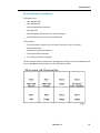
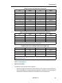
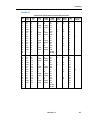
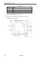
Tone Plans
Tone plans permit the station user to distinguish different stages of call progress and different
types of calls. Each tone is assigned a level which ensures an acceptable quality.
Australia
Tone Plan
Tone
ARS 2nd Dial
Busy
Camp-on
Conference
Confirmation
Dial Tone
Feature Active Dial
Interrupted Dial
Message Notification
Modem Answer
Override
Paging
Reorder
Ringback
Special Busy
Special Ringback
Transfer Dial
Voice Mail
Frequency
(Hz)
400/425
425
425
425
400/425
400/425
400/425
400/425
400/425
2025
1400
425
425
400/450
425
400/450
400/425
440
Cadence (s)
Continuous
0.375 on, 0.375 off, repeat
0.25 on, off
0.8 on, off
0.1 on, 0.1 off, 0.1 on, 0.7 off, repeat
Continuous
(0.95 on, 0.05 off) x 2, then (0.1 on, 0.1 off, 0.1 on, 0.7 off, repeat forever)
(0.95 on, 0.05 off) x 2, then (0.1 on, 0.1 off, 0.1 on, 0.7 off, repeat forever)
(0.95 on, 0.05 off) x 2, then (0.1 on, 0.1 off, 0.1 on, 0.7 off, repeat forever)
0.95 on, 0.05 off, repeat
0.2 on, off
0.25 on, off
2.5 on, 0.5 off, repeat
0.4 on, 0.2 off, 0.4 on, 2 off, repeat
0.375 on, 0.375 off, repeat
1.0 on, 2.0 off, repeat
(0.1 on, 0.1 off) x 3, then continuous
0.6 on, off
Release 3.3
19
3300 ICP Hardware User Guide
Tone
ARS 2nd Dial
Busy
Dial
Camp-on
Conference
Confirmation
Feature Active Dial
Interrupted Dial
Message Notification
Modem Answer
Override
Paging
Reorder
Ringback
Special Busy
Special Ringback
Transfer Dial
Voice Mail
Output Level
iONS
-15
-15
-15
-15
-15
-15
-15
-15
-15
-24
-27
-21
-15
-15
-15
-15
-15
-21
ONS
-15
-15
-15
-15
-15
-15
-15
-15
-15
-24
-27
-21
-15
-15
-15
-15
-15
-21
iOPS
-------------------------------------
OPS
-------------------------------------
iACO
-10
-10
-10
-10
-10
-10
-10
-10
-10
-19
-22
-16
-10
-10
-10
-10
-10
-16
iACOs
-13
-13
-13
-13
-13
-13
-13
-13
-13
-22
-25
-19
-13
-13
-13
-13
-13
-19
ACO
-10
-10
-10
-10
-10
-10
-10
-10
-10
-19
-22
-16
-10
-10
-10
-10
-10
-12
ACOs
-10
-10
-10
-10
-10
-10
-10
-10
-10
-19
-22
-16
-10
-10
-10
-10
-10
-12
DCO
-8
-8
-8
-8
-8
-8
-8
-8
-8
-17
-20
-14
-8
-8
-8
-8
-8
-14
ATT
-12
-12
-12
-12
-12
-12
-12
-12
-12
-21
-24
-18
-12
-12
-12
-12
-12
-18
Note: DTMF tones are supported.
Note: Digital (DGS) and IP (WAN) tones are conveyed as Real-Time Transfer Protocol (RTP) packets.
Note: "---" indicates that this interface is not supported in this country.
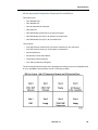
Brazil
Tone Plan
ARS 2nd Dial
Busy
Camp-on
Conference
Confirmation
Dial Tone
Feature Active Dial
Interrupted Dial
Message Notification
Frequency
(Hz)
425
425
440
440
425
425
425
425
425, 440, 425
Modem Answer
Override
Paging
Reorder
Ringback
Special Busy
Special Ringback
Transfer Dial
Voice Mail
2025
440
440
425
425
425
425
425
440
Tone
20
Cadence (s)
Continuous
0.25 on, 0.25 off, repeat
(0.1 on, 0.05 off) x 2
1 on, off
Continuous
Continuous
(0.1 on, 0.1 off) x 8, then continuous
(0.1 on, 0.1 off) x 8, then continuous
425 (0.2 on, 0.2 off) x 4, then 440 (0.2 on, 0.2 off) x 2, then 425 (0.1 on,
0.1 off) x 4, then 425 continuous
0.95 on, 0.05 off, repeat
0.8 on, off
0.2 on, off
0.25 on, 0.25 off, 0.75 on, 0.25 off, repeat
1 on, 4 off, repeat
0.5 on, 0.5 off, repeat
0.5 on, 0.5 off, 0.5 on, 2.5 off, repeat
(0.1 on, 0.1 off) x 3, then continuous
0.6 on, off
Release 3.3
Specifications
Tone
ARS 2nd Dial
Busy
Dial
Camp-on
Conference
Confirmation
Feature Active Dial
Interrupted Dial
Message Notification
Modem Answer
Override
Paging
Reorder
Ringback
Special Busy
Special Ringback
Transfer Dial
Voice Mail
Output Level
iONS
-23
-23
-23
-17
-19
-23
-23
-23
-23,
-17,
-23
-20
-17
-17
-23
-23
-23
-23
-23
-17
ONS
-23
-23
-23
-17
-19
-23
-23
-23
-23,
-17,
-23
-20
-17
-17
-23
-23
-23
-23
-23
-17
iOPS
-------------------
-------------------
OPS
-20
-20
-20
-14
-16
-20
-20
-20
-20,
-14,
-20
-17
-14
-14
-20
-20
-20
-20
-20
-14
iACO
-20
-20
-20
-14
-16
-20
-20
-20
-20,
-14,
-20
-17
-14
-14
-20
-20
-20
-20
-20
-14
iACOs
-20
-20
-20
-14
-16
-20
-20
-20
-20,
-14,
-20
-17
-14
-14
-20
-20
-20
-20
-20
-14
ACO
-20
-20
-20
-14
-16
-20
-20
-20
-20,
-14,
-20
-17
-14
-14
-20
-20
-20
-20
-20
-14
ACOs
-20
-20
-20
-14
-16
-20
-20
-20
-20,
-14,
-20
-17
-14
-14
-20
-20
-20
-20
-20
-14
DCO
-20
-20
-20
-14
-16
-20
-20
-20
-20,
-14,
-20
-17
-14
-14
-20
-20
-20
-20
-20
-14
ATT
-20
-20
-20
-14
-16
-20
-20
-20
-20,
-14,
-20
-17
-14
-14
-20
-20
-20
-20
-20
-14
Note: DTMF tones are supported.
Note: Digital (DGS) and IP (WAN) tones are conveyed as Real-Time Transfer Protocol (RTP) packets.
Note: "---" indicates that this interface is not supported in this country.
Release 3.3
21
3300 ICP Hardware User Guide
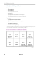
France
Tone Plan
ARS 2nd Dial
Busy
Camp-on
Conference
Confirmation
Dial Tone
Feature Active Dial
Interrupted Dial
Message Notification
Frequency
(Hz)
440
440
520
400
440
440
440
440
440, 520, 440
Modem Answer
Override
Paging
Reorder
Ringback
Special Busy
Special Ringback
Transfer Dial
Voice Mail
2025
1400
440
440
440
440
440
440
440
Tone
Cadence (s)
Continuous
0.5 on, 0.5 off, repeat
0.2 on, off
0.6 on, off
Continuous
Continuous
0.75 on, 0.75 off, then continuous
0.75 on, 0.75 off, then continuous
440 (0.75 on, 0.75 off) x 2, then 520 (0.2 on, 0.75 off) x 1, then 440 (0.75
on, 0.75 off, repeat forever)
0.95 on, 0.05 off, repeat
0.3 on, off
0.2 on, off
0.5 on, 0.5 off, repeat
1.5 on, 3.5 off, repeat
0.35 on, 0.35 off, repeat
0.4 on, 0.2 off, 0.4 on, 2.0 off, repeat
(0.1 on, 0.1 off) x 3, then continuous
0.6 on, off
Tone
ARS 2nd Dial
Busy
Dial
Camp-on
Conference
Confirmation
Feature Active Dial
Interrupted Dial
Message Notification
Modem Answer
Override
Paging
Reorder
Ringback
22
Output Level
iONS
ONS
iOPS
OPS
iACO
iACOs
ACO
ACOs
-20
-20
-20
-20
-20
-20
-20
-20
-20,
-23,
-20
-24
-23
-20
-20
-20
-20
-20
-20
-20
-20
-20
-20
-20
-20,
-23,
-20
-24
-23
-20
-20
-20
-------------------
-------------------
-----------
-----------
-15
-15
-15
-15
-15
-15
-15
-15
-15,
-18,
-15
-19
-18
-15
-15
-15
-18
-18
-18
-18
-18
-18
-18
-18
-18,
-21,
-18
-22
-21
-18
-18
-18
-15
-15
-15
-15
-15
-15
-15
-15
-15,
-18,
-15
-19
-18
-15
-15
-15
-15
-15
-15
-15
-15
-15
-15
-15
-15,
-18,
-15
-19
-18
-15
-15
-15
Release 3.3
DCO
ATT
-13
-17
-13
-17
-13
-17
-13
-17
-13
-17
-13
-17
-13
-17
-13
-17
-13,
-17,
-16,
-20,
-13
-17
-17
-21
-16
-20
-13
-17
-13
-17
-13
-17
Page 1 of 2
Specifications
Tone
Special Busy
Special Ringback
Transfer Dial
Voice Mail
Output Level
iONS
ONS
iOPS
OPS
iACO
iACOs
ACO
ACOs
-20
-20
-20
-23
-20
-20
-20
-23
---------
---------
-15
-15
-15
-18
-18
-18
-18
-21
-15
-15
-15
-18
-15
-15
-15
-18
DCO
ATT
-13
-17
-13
-17
-13
-17
-16
-20
Page 2 of 2
Note: DTMF tones are supported.
Note: Digital (DGS) and IP (WAN) tones are conveyed as Real-Time Transfer Protocol (RTP) packets.
Note: "---" indicates that this interface is not supported in this country.
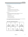
Germany
Tone Plan
Tone
Frequency
(Hz)
Cadence (s)
ARS 2nd Dial
425
Continuous
Busy
425
0.1 on, 0.4 off, repeat
Camp-on
425
0.25 on, off
Conference
425
0.25 on, off
Confirmation
425
0.1 on, 0.1 off, 0.1 on, 0.7 off, repeat
Dial
425
0.1 on, 0.1 on, 0.1 off, 0.1 on, 0.7 off, repeat
External Camp-on
425
0.1 on, 0.05 off, 0.1 on, 0.05 off
Feature Active Dial
425
(0.95 on, 0.05 off) x 2, then (0.1 on, 0.1 off, 01 on, 0.7 off, repeat
forever)
Interrupted Dial
425
(0.95 on, 0.05 off) x 2, then (0.1 on, 0.1 off, 0.1 on, 0.7 off, repeat
forever)
Message Notification
425
(0.95 on, 0.05 off) x 2, then (0.1 on, 0.1 off, 0.1 on, 0.7 off, repeat
forever)
Modem Answer
2025
0.95 on, 0.5 off, repeat
Override
1400
0.2 on, off
Paging
425
0.25 on, off
Reorder
425
0.2 on, 0.5 off, repeat
Ringback
425
1 on, 4 off, repeat
Special Busy
425
0.35 on, 0.35 off, repeat
Special Ringback
425
1 on, 4 off, repeat
Transfer Dial
425
0.1 on, .01 off, 0.1 on, 0.7 off, repeat
Voice Mail
440
0.6 on, off
Release 3.3
23
3300 ICP Hardware User Guide
Tone
ARS 2nd Dial
Busy
Dial
Camp-on
Conference
Confirmation
External Camp-on
Feature Active Dial
Interrupted Dial
Message Notification
Modem Answer
Override
Paging
Reorder
Ringback
Special Busy
Special Ringback
Transfer Dial
Voice Mail
Output Level
iONS
-15
-15
-15
-15
-15
-15
-15
-15
-15
-15
-24
-27
-21
-15
-15
-15
-15
-15
-21
ONS
-15
-15
-15
-15
-15
-15
-15
-15
-15
-15
-24
-27
-21
-15
-15
-15
-15
-15
-21
iOPS
-12
-12
-12
-12
-12
-12
-12
-12
-12
-12
-21
-24
-18
-12
-12
-12
-12
-12
-18
OPS
---------------------------------------
iACO iACOs
-10
-13
-10
-13
-10
-13
-10
-13
-10
-13
-10
-13
-10
-13
-10
-13
-10
-13
-10
-13
-19
-22
-22
-25
-16
-19
-10
-13
-10
-13
-10
-13
-10
-13
-10
-13
-16
-19
ACO
-10
-10
-10
-10
-10
-10
-10
-10
-10
-10
-19
-22
-16
-10
-10
-10
-10
-10
-16
ACOs
-10
-10
-10
-10
-10
-10
-10
-10
-10
-10
-19
-22
-16
-10
-10
-10
-10
-10
-16
DCO
-8
-8
-8
-8
-8
-8
-8
-8
-8
-8
-17
-20
-14
-8
-8
-8
-8
-8
-14
ATT
-12
-12
-12
-12
-12
-12
-12
-12
-12
-12
-21
-24
-18
-12
-12
-12
-12
-12
-18
Note: DTMF tones are supported.
Note: Digital (DGS) and IP (WAN) tones are conveyed as Real-Time Transfer Protocol (RTP) packets.
Note: "---" indicates that this interface is not supported in this country.
Italy
Tone Plan
Tone
ARS 2nd Dial
Busy
Camp-on
Conference
Confirmation
Dial
Feature Active Dial
Interrupted Dial
Message Notification
Modem Answer
Override
Paging
Reorder
Ringback
Special Busy
Special Ringback
Transfer Dial
Voice Mail
24
Frequency
(Hz)
425
425
425
425
425
350/425
350/425
425
425
2025
425
425
425
425
425
425
350/425
440
Cadence (s)
0.2 on, 0.2 off, 0.6 on, 1 off, repeat forever
0.2 on, 0.2 off, repeat forever
0.2 on, 0.1 off, 0.2 on, 0.1 off
0.2 on, off
0.1 on, 0.1 off, 0.1 on, .07 off, repeat
Continuous
0.7 on, 0.7 off, repeat forever
0.9 on, 0.1 off, then (0.1 on, 0.1 off, 0.1 on, 0.7 off, repeat forever)
0.7 on, 0.7 off
0.95 on, 0.05 off, repeat
0.2 on, off
0.2 on, off
0.2 on, 0.2 off, repeat forever
1 on, 4 off, repeat
0.2 on, 0.2 off, repeat forever
1 on, 4 off, repeat
0.75 on, 0.75 off, repeat
0.6 on, off
Release 3.3
Specifications
Tone
ARS 2nd Dial
Busy
Dial
Camp-on
Conference
Confirmation
Feature Active Dial
Interrupted Dial
Message Notification
Modem Answer
Override
Paging
Reorder
Ringback
Special Busy
Special Ringback
Transfer Dial
Voice Mail
Output Levels
iONS
ONS
iOPS
OPS
iACO
iACOs
ACO
ACOs
DCO
ATT
-17
-20
-17
-20
-17
-20
-17
-20
-17
-17
-20
-17
-20
-17
-20
-17
-20
-24
-27
-20
-17
-20
-17
-20
-17
-20
-17
-20
-17
-20
-21
-13
-16
-13
-16
-13
-16
-13
-16
-13
-13
-16
-13
-16
-13
-16
-13
-16
-20
-23
-16
-13
-16
-13
-16
-13
-16
-13
-16
-13
-16
-17
-14
-17
-14
-17
-14
-17
-14
-17
-14
-14
-17
-14
-17
-14
-17
-14
-17
-21
-24
-17
-14
-17
-14
-17
-14
-17
-14
-17
-14
-17
-18
-12
-15
-12
-15
-12
-15
-12
-15
-12
-12
-15
-12
-15
-12
-15
-12
-15
-19
-22
-15
-12
-15
-12
-15
-12
-15
-12
-15
-12
-15
-16
-12
-15
-12
-15
-12
-15
-12
-15
-12
-12
-15
-12
-15
-12
-15
-12
-15
-19
-22
-15
-12
-15
-12
-15
-12
-15
-12
-15
-12
-15
-16
-16
-19
-15
-18
-15
-18
-15
-18
-15
-16
-19
-16
-19
-15
-18
-16
-19
-22
-25
-18
-15
-18
-15
-18
-15
-18
-16
-19
-15
-18
-19
-16
-19
-16
-19
-16
-19
-16
-19
-16
-16
-19
-16
-19
-16
-19
-16
-19
-23
-26
-19
-16
-19
-16
-19
-16
-19
-16
-19
-16
-19
-20
-15
-18
-15
-18
-15
-18
-15
-18
-15
-15
-18
-15
-18
-15
-18
-15
-18
-22
-25
-18
-15
-18
-15
-18
-15
-18
-15
-18
-15
-18
-19
-10
-13
-10
-13
-10
-13
-10
-13
-10
-10
-13
-10
-13
-10
-13
-10
-13
-17
-20
-13
-10
-13
-10
-13
-10
-13
-10
-13
-10
-13
-14
-16
-19
-16
-19
-16
-19
-16
-19
-16
-16
-19
-16
-19
-16
-19
-16
-19
-23
-26
-19
-16
-19
-16
-19
-16
-19
-16
-19
-16
-19
-20
Note: DTMF tones are supported.
Note: Digital (DGS) and IP (WAN) tones are conveyed as Real-Time Transfer Protocol (RTP) packets.
Note: "---" indicates that this interface is not supported in this country.
Release 3.3
25
3300 ICP Hardware User Guide
Latin America
Tone Plan
Tone
Frequency
(Hz)
Cadence (s)
ARS 2nd Dial
425
Continuous
Busy
480/620
0.5 on, 0.5 off, repeat
Camp-on
440
0.1 on, 0.05 off, repeat x 2
Conference
440
1 on, off
Confirmation
350/440
Continuous
Dial
350/440
Continuous
Feature Active Dial
350/440
(0.1 on, 0.1 off) x 8, then continuous
Interrupted Dial
350/440
(0.1 on, 0.1 off) x 8, then continuous
Message Notification
350/440
(0.1 on, .01 off) x 4, (0.2 on, 0.2 off) x 2, (0.1 on, 0.1 off) x 4, then
continuous
Modem Answer
2025
0.95 on, 0.05 off, repeat
Override
440
0.8 on, off
Paging
440
0.2 on, off
Reorder
480/620
0.25 on, 0.25 off, repeat
Ringback
440/480
1 on, 3 off, repeat
Special Busy
480/620
0.5 on, 0.5 off, repeat
Special Ringback
440/480
0.5 on, 0.5 off, 0.5 on, 2.5 off, repeat
Transfer Dial
350/440
(0.1 on, 0.1 off) x 3, then continuous
Voice Mail
440
0.6 on, off
Tone
Output Level
iONS
ONS
iOPS
OPS
iACO
iACOs
ACO
ACOs
DCO
ATT
ARS 2nd Dial
-23
-23
-23
-20
-20
-20
-20
-20
-20
-20
Busy
-27
-27
-27
-24
-24
-24
-24
-24
-24
-24
Dial
-23
-23
-23
-20
-20
-20
-20
-20
-20
-20
Camp-on
-17
-17
-17
-14
-14
-14
-14
-14
-14
-14
Conference
-19
-19
-19
-16
-16
-16
-16
-16
-16
-16
Confirmation
-23
-23
-23
-20
-20
-20
-20
-20
-20
-20
Feature Active Dial
-22
-22
-22
-19
-19
-19
-19
-19
-19
-19
Interrupted Dial
-23
-23
-23
-20
-20
-20
-20
-20
-20
-20
Message Notification
-17
-17
-17
-14
-14
-14
-14
-14
-14
-14
Modem Answer
-20
-20
-20
-17
-17
-17
-17
-17
-17
-17
Override
-17
-17
-17
-14
-14
-14
-14
-14
-14
-14
Paging
-17
-17
-17
-14
-14
-14
-14
-14
-14
-14
Reorder
-27
-27
-27
-24
-24
-24
-24
-24
-24
-24
Ringback
-22
-22
-22
-19
-19
-19
-19
-19
-19
-19
Special Busy
-27
-27
-27
-24
-24
-24
-24
-24
-24
-24
Page 1 of 2
26
Release 3.3
Specifications
Tone
Output Level
iONS
ONS
iOPS
OPS
iACO
iACOs
ACO
ACOs
DCO
ATT
Special Ringback
-22
-22
-22
-19
-19
-19
-19
-19
-19
-19
Transfer Dial
-23
-23
-23
-20
-20
-20
-20
-20
-20
-20
Voice Mail
-17
-17
-17
-14
-14
-14
-14
-14
-14
-14
Page 2 of 2
Note: DTMF tones are supported.
Note: Digital (DGS) and IP (WAN) tones are conveyed as Real-Time Transfer Protocol (RTP) packets.
Note: "---" indicates that this interface is not supported in this country.
Netherlands
Tone Plan
Tone
Frequency (Hz)
Cadence (s)
ARS 2nd Dial
425
Continuous
Busy
425
0.5 on, 0.5 off, repeat
Camp-on
425
0.5 on, off
Conference
425
0.1 on, off
Confirmation
425
Continuous
Dial
425
Continuous
Feature Active Dial
425
0.75 on, 0.75 off, repeat
Interrupted Dial
425
0.4 on, .04 off, repeat forever
Message Notification
425/400/425
(0.75 on, .075 off ) x 2, (0.1 on, 0.75 off), (0.75on, 0.75 off, repeat)
Modem Answer
2025
0.95 on, 0.05 off, repeat
Override
425
0.2 on, off
Paging
425
0.2 on, off
Reorder
425
0.07 on, 0.07 off, repeat
Ringback
425
1 on, 4 off, repeat
Special Busy
425
0.5 on, 0.5 off, repeat
Special Ringback
425
1 on, 4 off, repeat
Transfer Dial
425
0.75 on, 0.75 off, repeat
Voice Mail
440
0.6 on, off
Release 3.3
27
3300 ICP Hardware User Guide
Tone
Output Levels
iONS
ONS
iOPS
OPS
iACO iACOs
ACO
ACOs
DCO
ATT
ARS 2nd Dial
-16
-16
-13
---
-11
Busy
-16
-16
-13
---
-11
-14
-11
-11
-9
-13
-14
-11
-11
-9
-13
Dial
-16
-16
-13
---
-11
-14
-11
-11
-9
-13
Camp-on
-16
-16
-13
Conference
-18
-18
-15
---
-11
-14
-11
-11
-9
-13
---
-13
-16
-13
-13
-11
Confirmation
-16
-16
-15
-13
---
-11
-14
-11
-11
-9
-13
Feature Active Dial
-16
-16
-13
---
-11
-14
-11
-11
-9
-13
Interrupted Dial
Message Notification
-16
-16
-13
---
-11
-14
-11
-11
-9
-13
-16
-16
-13
---
-11
-14
-11
-11
-9
-13
Modem Answer
-24
-24
-21
---
-19
-22
-19
-19
-17
-21
Override
-22
-22
-19
---
-17
-20
-17
-17
-15
-19
Paging
-23
-23
-20
---
-18
-21
-18
-18
-16
-20
Reorder
-16
-16
-13
---
-11
-14
-11
-11
-9
-13
Ringback
-16
-16
-13
---
-11
-14
-11
-11
-9
-13
Special Busy
-16
-16
-13
---
-11
-14
-11
-11
-9
-13
Special Ringback
-16
-16
-13
---
-11
-14
-11
-11
-9
-13
Transfer Dial
-16
-16
-13
---
-11
-14
-11
-11
-9
-13
Voice Mail
-23
-23
-20
---
-18
-21
-18
-18
-16
-20
Note: DTMF tones are supported.
Note: Digital (DGS) and IP (WAN) tones are conveyed as Real-Time Transfer Protocol (RTP) packets.
Note: "---" indicates that this interface is not supported in this country.
New Zealand
Tone Plan
Tone
ARS 2nd Dial
Busy
Camp-on
Conference
Confirmation
Dial Tone
Feature Active Dial
Interrupted Dial
Message Notification
Modem Answer
Override
Paging
Reorder
28
Frequency
(Hz)
400
400
520
400
1400
400
400
400
400, 520,
400
2025
1400
440
400
Cadence (s)
Continuous
0.5 on, 0.5 off, repeat
0.2 on, off
0.6 on, off
Continuous
Continuous
0.75 on, 0.75 off, then continuous
0.75 on, 0.75 off, then continuous
400 (0.75 on, 0.75 off) x 2, then 520 (0.2 on, 0.75 off) x 1, then 400 (0.75
on, 0.75 off, repeat forever)
0.95 on, 0.05 off, repeat
0.3 on, off
0.2 on, off
0.075 on, 0.1 off, 0.075 on, 0.75 off, repeat
Page 1 of 2
Release 3.3
Specifications
Tone Plan (continued)
Tone
Ringback
Special Busy
Special Ringback
Transfer Dial
Voice Mail
Frequency
(Hz)
400/450
400
400/450
400
440
Cadence (s)
1 on, 2 off, repeat
0.35 on, 0.35 off, repeat
0.4 on, 0.2 off, 0.4 on, 2.0 off, repeat forever
(0.1 on, 0.1 off) x 3, then continuous
0.6 on, off
Page 2 of 2
Tone
ARS 2nd Dial
Busy
Dial
Camp-on
Conference
Confirmation
Feature Active Dial
Interrupted Dial
Message Notification
Modem Answer
Override
Paging
Reorder
Ringback
Special Busy
Special Ringback
Transfer Dial
Voice Mail
Output Level
iONS
ONS
iOPS
OPS
iACO
iACOs
ACO
ACOs
DCO
ATT
-11
-11
-11
-11
-14
-11
-11
-11
-11,
-13,
-11
-20
-13
-17
-11
-11
-11
-11
-11
-17
-9
-9
-9
-9
-12
-9
-9
-9
-9,
-11,
-9
-18
-11
-15
-9
-9
-9
-9
-9
-15
-------------------
-10
-10
-10
-10
-13
-10
-10
-10
-10,
-12,
-10
-19
-12
-16
-10
-10
-10
-10
-10
-16
-9
-9
-9
-7
-10
-9
-9
-9
-9,
-11,
-9
-16
-9
-13
-9
-9
-9
-9
-9
-13
-8
-8
-8
-6
-8
-8
-8
-8
-8,
-10,
-8
-15
-8
-12
-8
-8
-8
-8
-8
-12
-10
-10
-10
-8
-11
-10
-10
-10
-10,
-12,
-10
-17
-10
-14
-10
-10
-10
-10
-10
-14
-10
-10
-10
-8
-11
-10
-10
-10
-10,
-12,
-10
-17
-10
-14
-10
-10
-10
-10
-10
-14
-10
-10
-10
-8
-11
-10
-10
-10
-10,
-12,
-10
-17
-10
-14
-10
-10
-10
-10
-10
-14
-10
-10
-10
-8
-11
-10
-10
-10
-10,
-12,
-10
-17
-10
-14
-10
-10
-10
-10
-10
-14
-------------------
Note: DTMF tones are supported.
Note: Digital (DGS) and IP (WAN) tones are conveyed as Real-Time Transfer Protocol (RTP) packets.
Note: "---" indicates that this interface is not supported in this country.
Release 3.3
29
3300 ICP Hardware User Guide
North America
Tone Plan
ARS 2nd Dial
Busy
Camp-on
Conference
Confirmation
Dial Tone
Feature Active Dial
Interrupted Dial
Message Notification
Frequency
(Hz)
350/440
480/620
440
440
350/440
350/440
350/440
350/440
350/440
Modem Answer
Override
Paging
Reorder
Ringback
Special Busy
Special Ringback
Transfer Dial
Voice Mail
2025
440
440
480/620
440/480
480/620
440/480
350/440
440
Tone
Cadence (s)
Continuous
0.5 on, 0.5 off, repeat
0.1 on, 0.05 off, repeat x 2
1 on, off
Continuous
Continuous
(0.1 on, 0.1 off) x 8, then continuous
(0.1 on, 0.1 off) x 8, then continuous
350/440 (0.1 on, 0.1 off) x 4, then 440 (0.2 on, 0.2 off) x 2, then 350/440
(0.1 on, 0.1 off) x 4, then 350/440 continuous
0.95 on, .005 off, repeat
0.8 on, off
0.2 on, off
0.25 on, 0.25 off, repeat
1 on, 3 off, repeat
0.5 on, 0.5 off, repeat
0.5 on, 0.5 off, 0.5 on, 2.5 off, repeat
(0.1 on, 0.1 off) x 3, then continuous
0.6 on, off
Tone
Output Level
iONS
ARS 2nd Dial
Busy
Dial
Camp-on
Conference
Confirmation
Feature Active Dial
Interrupted Dial
Message Notification
Modem Answer
Override
Paging
Reorder
Ringback
Special Busy
Special Ringback
Transfer Dial
Voice Mail
-23
-27
-23
-17
-19
-23
-22
-23
-17
-20
-17
-17
-27
-22
-27
-22
-23
-17
ONS
-23
-27
-23
-17
-19
-23
-22
-23
-17
-20
-17
-17
-27
-22
-27
-22
-23
-17
iOPS
-23
-27
-23
-17
-19
-23
-22
-23
-17
-20
-17
-17
-27
-22
-27
-22
-23
-17
OPS
-20
-24
-20
-14
-16
-20
-19
-20
-14
-17
-14
-14
-24
-19
-24
-19
-20
-14
iACO iACOs
-20
-24
-20
-14
-16
-20
-19
-20
-14
-17
-14
-14
-24
-19
-24
-19
-20
-14
-20
-24
-20
-14
-16
-20
-19
-20
-14
-17
-14
-14
-24
-19
-24
-19
-20
-14
ACO ACOs DCO
-20
-24
-20
-14
-16
-20
-19
-20
-14
-17
-14
-14
-24
-19
-24
-19
-20
-14
-20
-24
-20
-14
-16
-20
-19
-20
-14
-17
-14
-14
-24
-19
-24
-19
-20
-14
-20
-24
-20
-14
-16
-20
-19
-20
-14
-17
-14
-14
-24
-19
-24
-19
-20
-14
ATT
-20
-24
-20
-14
-16
-20
-19
-20
-14
-17
-14
-14
-24
-19
-24
-19
-20
-14
Note: DTMF tones are supported.
Note: Digital (DGS) and IP (WAN) tones are conveyed as Real-Time Transfer Protocol (RTP) packets.
Note: "---" indicates that this interface is not supported in this country.
30
Release 3.3
Specifications
Portugal
Tone
Tone Plan
Frequency (Hz)
Cadence (s)
ARS 2nd Dial
400
Continuous
Busy
425
0.2 on, 0.2 off, repeat
Camp-on
425
0.2 on, .01 off, 0.2 on, 0.1 off
Conference
425
0.2 on, off
Confirmation
425
0.1 on, 0.1 off, 0.1 on, 0.7 off, repeat
Dial
350/425
Continuous
Feature Active Dial
350/425
0.7 on, 0.7 off, repeat
Interrupted Dial
425
0.9 on, 0.1 off, then (0.1 on, 0.1 off, 0.1 on, 0.7 off, repeat
forever)
Message Notification
425
0.7 on, .07soff
Modem Answer
2025
0.95 on, 0.05 off, repeat
Override
425
0.2 on, off
Paging
425
0.2 on, off
Reorder
425
0.2 on, 0.2 off, repeat
Ringback
425
1 on, 4 off, repeat
Special Busy
425
0.2 on, 0.2 off, repeat
Special Ringback
425
1 on, 4 off, repeat
Transfer Dial
350/425
Continuous
Voice Mail
440
0.6 on, off
Tone
ARS 2nd Dial
Busy
Dial
Camp-on
Conference
Confirmation
Feature Active Dial
Interrupted Dial
Message Notification
Modem Answer
Override
Paging
Reorder
Ringback
Special Busy
Special Ringback
Transfer Dial
Voice Mail
Output Levels
iONS
-17
-17
-17
-17
-17
-17
-17
-17
-17
-24
-27
-20
-17
-17
-17
-17
-17
-21
ONS
-17
-17
-17
-17
-17
-17
-17
-17
-17
-24
-27
-20
-17
-17
-17
-17
-17
-21
iOPS
-14
-14
-14
-14
-14
-14
-14
-14
-14
-21
-24
-17
-14
-14
-14
-14
-14
-18
OPS
-------------------------------------
iACO iACOs
-12
-15
-12
-15
-12
-15
-12
-15
-12
-15
-12
-15
-12
-15
-12
-15
-12
-15
-19
-22
-22
-25
-15
-18
-12
-15
-12
-15
-12
-15
-12
-15
-12
-15
-16
-19
ACO
-12
-12
-12
-12
-12
-12
-12
-12
-12
-19
-22
-15
-12
-12
-12
-12
-12
-16
ACOs
-12
-12
-12
-12
-12
-12
-12
-12
-12
-19
-22
-15
-12
-12
-12
-12
-12
-16
DCO
-10
-10
-10
-10
-10
-10
-10
-10
-10
-17
-20
-13
-10
-10
-10
-10
-10
-14
ATT
-14
-14
-14
-14
-14
-14
-14
-14
-14
-21
-24
-17
-14
-14
-14
-14
-14
-18
Note: DTMF tones are supported.
Note: Digital (DGS) and IP (WAN) tones are conveyed as Real-Time Transfer Protocol (RTP) packets.
Note: "---" indicates that this interface is not supported in this country.
Release 3.3
31
3300 ICP Hardware User Guide
Spain
Tone Plan
Tone
Frequency
(Hz)
Cadence (s)
ARS 2nd Dial
425
Continuous
Busy
425
0.2 on, 0.2 off, repeat
Camp-on
425
0.6 on, 0.2 off, 0.6 on, off
Conference
1400
0.4 on, off
Confirmation
425
Continuous
Dial
425
Continuous
Feature Active Dial
425
(0.1 on, 0.1 off) x 8, then continuous
Interrupted Dial
425
(0.1 on, 0.1 off), repeat x 8, then continuous
Message Notification
425, 440, 425
425 (0.1 on, .01 off) x 4, then 440 (0.2 on, 0.2 off) x 2, then 425 (0.1
on, 0.1 off) x 4, then 425 continuous
Modem Answer
2025
0.95 on, 0.05 off, repeat
Override
1400
0.2 on, off
Paging
440
0.2 on, off
Reorder
425
0.2 on, 0.2 off, 0.2 on, 0.6 off, repeat
Ringback
425
1.5 on, 3 off, repeat
Special Busy
425
0.2 on, 0.2 off, repeat
Special Ringback
425
0.5 on, 0.5 off, 0.5 on, 2.5 off, repeat
Transfer Dial
425
0.1 on, 0.s off, 0.1 on, 0.1 off, 0.1 on, 0.1 off, then continuous
Voice Mail
440
0.6 on, off
Tone
Output Levels
iONS
ONS
iOPS
OPS
iACO
iACOs
ACO
ACOs
DCO
ATT
ARS 2nd Dial
-17
-17
-14
---
-12
-15
-12
-12
-10
-14
Busy
-17
-17
-14
---
-12
-15
-12
-12
-10
-14
Dial
-17
-17
-14
---
-12
-15
-12
-12
-10
-14
Camp-on
-17
-17
-14
---
-12
-15
-12
-12
-10
-14
Conference
-17
-17
-14
---
-12
-15
-12
-12
-10
-14
Confirmation
-17
-17
-14
---
-12
-15
-12
-12
-10
-14
Feature Active Dial
-17
-17
-14
---
-12
-15
-12
-12
-10
-14
Interrupted Dial
-17
-17
-14
---
-12
-15
-12
-12
-10
-14
Message Notification
-17
-17
-14
---
-12
-15
-12
-12
-10
-14
Modem Answer
-24
-24
-21
---
-19
-22
-19
-19
-17
-21
Override
-27
-27
-24
---
-22
-25
-22
-22
-20
-24
Paging
-21
-21
-18
---
-16
-19
-16
-16
-14
-18
Reorder
-17
-17
-14
---
-12
-15
-12
-12
-10
-14
Ringback
-17
-17
-14
---
-12
-15
-12
-12
-10
-14
Special Busy
-17
-17
-14
---
-12
-15
-12
-12
-10
-14
Special Ringback
-17
-17
-14
---
-12
-15
-12
-12
-10
-14
Page 1 of 2
32
Release 3.3
Specifications
Tone
Output Levels
iONS
ONS
iOPS
OPS
iACO
iACOs
ACO
ACOs
DCO
ATT
Transfer Dial
-17
-17
-14
---
-12
-15
-12
-12
-10
-14
Voice Mail
-21
-21
-18
---
-16
-19
-16
-16
-14
-18
Page 2 of 2
Note: DTMF tones are supported.
Note: Digital (DGS) and IP (WAN) tones are conveyed as Real-Time Transfer Protocol (RTP) packets.
Note: "---" indicates that this interface is not supported in this country.
United Kingdom
Tone Plan
Tone
Frequency
(Hz)
Cadence (s)
ARS 2nd Dial
350/440
Continuous
Busy
400
0.35 on, 0.35 off, repeat
Camp-on
400
0.1 on, off
Conference
400
0.1 on, off
Confirmation
350/440
Continuous
Dial
350/440
Continuous
Feature Active Dial
350/440
0.75 on, 0.75 off, repeat
Interrupted
1400
0.1 on, off
Message Notification
350/440
350/440 (0.75 on, 0.75 off) x 2, then 440 (0.1 on, 0.75 off), then
350/440 (0.75 on, 0.75 off, repeat)
Modem Answer
2025
0.95 on, 0.05 off, repeat
Number Unobtainable
400
Continuous
Paging
440
0.2 on, off
Ringing (External)
400/450
1 on, 2 off, repeat
Special Busy
400
0.35 on, 0.35 off, repeat
Special Ringing
(Internal)
400/450
0.4 on, 0.2 of, 0.4 on, 2 off, repeat
Transfer Dial
350/440
0.75 on, 0.75 off, repeat
Interrupted Dial
350/440
0.75 on, 0.75 off, repeat
Voice Mail
440
0.6 on, off
Release 3.3
33
3300 ICP Hardware User Guide
Tone
ARS 2nd Dial
Busy
Dial
Camp-on
Conference
Confirmation
Feature Active Dial
Interrupted Dial
Message Notification
Modem Answer
Override
Paging
Reorder
Ringback
Special Busy
Special Ringback
34
Output Level
iONS
ONS
iOPS
OPS
iACO
-8
-12
-17
-22
-9
-14
-19
-8
-12
-17
-22
-9
-14
-19
-14
-8
-12
-17
-22
-8
-12
-17
-22
-8
-12
-17
-22
-9
-14
-20
-18
-19
-9
-14
-19
-12
-17
-22
-8
-12
-17
-22
-12
-17
-22
-7
-11
-16
-21
-8
-13
-18
-7
-11
-16
-21
-8
-13
-18
-13
-7
-11
-16
-21
-7
-11
-16
-21
-7
-11
-16
-21
-8
-13
-19
-17
-18
-8
-13
-18
-11
-16
-21
-7
-11
-16
-21
-11
-16
-21
-5
-9
-14
-19
-6
-11
-16
-5
-9
-14
-19
-6
-11
-16
-11
-5
-9
-14
-19
-5
-9
-14
-19
-5
-9
-14
-19
-6
-11
-17
-15
-16
-6
-11
-16
-9
-14
-19
-5
-9
-14
-19
-9
-14
-19
-10
-14
-19
-24
-11
-16
-21
-10
-14
-19
-24
-11
-16
-21
-16
-10
-14
-19
-24
-10
-14
-19
-24
-10
-14
-19
-24
-11
-16
-22
-20
-21
-11
-16
-21
-14
-19
-21
-10
-14
-19
-24
-14
-19
-24
-4
-8
-13
-18
-5
-10
-15
-4
-8
-13
-18
-5
-10
-15
-10
-4
-8
-13
-18
-4
-8
-13
-18
-4
-8
-13
-18
-5
-10
-16
-14
-15
-5
-10
-15
-8
-13
-18
-4
-8
-13
-18
-8
-13
-18
Release 3.3
iACO
s
-3
-7
-12
-17
-4
-9
-14
-3
-7
-12
-17
-4
-9
-14
-9
-3
-7
-12
-17
-3
-7
-12
-17
-3
-7
-12
-17
-4
-9
-15
-13
-14
-4
-9
-14
-7
-12
-17
-3
-7
-12
-17
-7
-12
-17
ACO
ACOs
-4
-8
-13
-18
-5
-10
-15
-4
-8
-13
-18
-5
-10
-15
-10
-4
-8
-13
-18
-4
-8
-13
-18
-4
-8
-13
-18
-5
-10
-16
-14
-15
-5
-10
-15
-8
-13
-18
-4
-8
-13
-18
-8
-13
-18
-4
-8
-13
-18
-5
-10
-15
-4
-8
-13
-18
-5
-10
-15
-10
-4
-8
-13
-18
-4
-8
-13
-18
-4
-8
-13
-18
-5
-10
-16
-14
-15
-5
-10
-15
-8
-13
-18
-4
-8
-13
-18
-8
-13
-18
DCO
ATT
-5
-4
-9
-8
-14
-13
-19
-18
-6
-5
-11
-10
-16
-15
-5
-4
-9
-8
-14
-13
-19
-18
-6
-5
-11
-10
-16
-15
-11
-10
-5
-4
-9
-8
-14
-13
-19
-18
-5
-4
-9
-8
-14
-13
-19
-18
-5
-4
-9
-8
-14
-13
-19
-18
-6
-5
-11
-10
-17
-16
-15
-14
-16
-15
-6
-5
-11
-10
-16
-15
-9
-8
-14
-13
-19
-18
-5
-4
-9
-8
-14
-13
-19
-18
-9
-8
-14
-13
-19
-18
Page 1 of 2
Specifications
Tone
Transfer Dial
Voice Mail
Output Level
iONS
ONS
iOPS
OPS
iACO
-8
-12
-19
-7
-11
-18
-5
-9
-16
-10
-14
-21
-4
-8
-15
iACO
s
-3
-7
-14
ACO
ACOs
-4
-8
-15
-4
-8
-15
DCO
ATT
-5
-4
-9
-8
-16
-15
Page 2 of 2
Note: DTMF tones are supported.
Note: Digital (DGS) and IP (WAN) tones are conveyed as (RTP) packets.
Note: "---" indicates that this interface is not supported in this country.
E2T Compression
The 3300 ICP supports G.729ac voice compression. The compression of a standard call
effectively reduces the voice payload bandwidth required per call from 64 kbps to approximately
8 kbps plus packet overhead. Voice compression on the 3300 ICP can be divided into two
types: IP phone-to IP phone and IP phone to TDM/analog devices.
With IP-phone-to-IP phone connection, where included, voice compression is handled by the
phone’s own DSP resources. An exception to this is when a basic IP set is used such as the
Mitel Networks 5001 IP Phone, 5201 IP Phone, 5005 IP phone or 5205 IP Phone.
For an IP phone to a non IP device G.729ac compression will be provided through the purchase
of compression licenses and 21161 Quad DSP Modules. One DSP module provides up to 32
channels of voice compression. The 250 User and 700 User controllers have the capacity for
the installation of two modules providing a maximum of 64 channels of compression.
Compression is carried out by the 21161 Quad DSP under the control of the E2T.
Compression zones are programmed on the 3300 ICP. Phones are typically put in the default
zone which does not have compression turned on and all calls within this zone will not be
compressed. Phones can be placed on other zones and compression may be turned on or off.
Full details are covered in the System Administration Tool online help.
In the following example, when an IP device (assigned to a non-default zone) calls a TDM
device, G.729ac compression will be invoked on the LAN or WAN side of the call providing
there are adequate compression resources available in the controller.
The same applies to calls that originate from a TDM device and terminate on an IP device
assuming compression is required.
Release 3.3
35
3300 ICP Hardware User Guide
When controllers are networked together the compression becomes more complex.
The following examples are assuming that the IP devices are in different compression zones.
The WAN link is assumed to be G.729 compressed. The LAN link is assumed to be in the same
compression zone and running G.711.
An IP device on one system connecting to an IP device on a different system across a WAN
link (IP trunking) does not require a compression license as the conversion done on the DSP
resources in the IP phones.
An IP device on one system connecting to a TDM device on a different system across a WAN
link (IP trunking) will consume one compression licence from the system that the TDM device
is connected to.
A TDM device on one system connecting to a TDM device on a different system using IP
trunking will consume one compression license on each of the systems.
Conference/ACD Silent Monitor and compression licences
Conference calls require system DSP resources for E2T compression.
36
Release 3.3
Specifications
The following examples assume that compression is not being used within the LAN, each node
is in a separate compression zone and Node A is the host of each conference call.
For example: A three-party conference is established between a TDM device and an IP device
on Node A across a LAN, and an IP device on Node B across a WAN.
•
Assuming that a compression license is not required for the connection within Node
A (LAN) then one compression license is required on Node A for voice compression
to the IP device on Node B.
•
Adding a conference member using an IP device located on Node B will consume
a compression license on Node A.
•
Adding a conference member using a TDM device on Node B will consume a
compression license on Node A and a compression license on Node B.
For example: A three party conference is set up between an IP device on Node A, an IP device
on Node B, and an IP device on Node C. The nodes are connected over the WAN using IP
trunking.
•
Two compression licenses are required on Node A for the connection to the IP
device on Node B and the IP device on Node C.
•
Adding conference members located on either Node B or Node C will require an
additional compression channel on Node A for each IP device added.
For example: A three party conference is set up between a TDM device on Node A, a TDM
device on Node B, and a TDM device on Node C. The nodes are connected over the WAN
using IP trunking.
•
Two compression licenses are required on Node A for the WAN connection to Node
B and Node C.
•
One compression license is required on Node B for the WAN connection to Node A.
•
One compression license is required on Node C for the WAN connection to Node A.
Voice mail and compression
Compression is not invoked with calls to voice mail. No licences are required.
Music on Hold and compression
Music played through an IP connection will be compressed based on the same rules as any
other connection to that phone. Because the music source is by nature a TDM device, if sent
through a connection that requires compression, it will use a compression license on the system
to which the music is connected, and on the second system of an IP trunked call if it goes to a
TDM phone there.
Release 3.3
37
3300 ICP Hardware User Guide
3300 Controller
100 Controller
Mitel Networks™ 3300 - 100 Controller Components
Front Panel
•
Remote Alarm port (DB-9 connector)
•
Two RS-232 ports (DB-9 connectors) (Printer and Maintenance)
•
Dual fiber interface module (FIM) ports to support the NSUs (Network Services Units) or
the Peripheral unit.
•
Two 10/100 Ethernet connections via RJ-45 (8-pin CAT5 cross-over cable)
Note: Only the first connection is fully provisioned.
•
Two 2 MB CIM (copper interface module) ports are used to connect to the ASUs (Analog
Services Units) with cross-over Category 5 cable
•
Alarm LEDs.
Rear Panel
•
Power connector
•
Protective ground to ground the chassis.
Internal Components
38
•
20 GB EIDE hard drive
•
256 Mbytes of memory on the 300 MHz RTC that provides main control
•
Stratum 3 clock
•
Up to 64 channel echo canceller (300 MHz)
•
64 Ethernet to Time Division Multiplex (E2T) channels (300 MHz)
Release 3.3
Specifications
•
Power fail protected real-time clock
•
Digital Signal Processor (DSP) (provides telecom functions)
•
Two cooling fans.
Configurations
There are several configuration options for the 3300 ICP (100 Controller):
•
100 User System without Compression
•
100 User System with 32 Compression Channels
•
100 User System with 30 Voice Mail Ports
•
100 User System with 32 Compression Channels and 30 Voice Mail Ports
The following top view diagram shows the MMC/A slot numbering convention. All MMC modules
allow connectors to protrude through the front panel.
100 USER SYSTEM
Release 3.3
39
3300 ICP Hardware User Guide
100 User System without Compression
This system uses:
•
One embedded 300 MHz RTC/E2T processor
•
One embedded 64 Channel Echo Canceller
•
One dual FIM
•
One DSP Module (21161) for telecom support
This provides:
•
4 DSP devices for telecom functions for 100 users
•
64 channels of Echo Cancellation
•
2 External FIM connections
•
2 ASU connections (CIM ports) for up to 48 ONS ports
The two external FIM connections are for providing connectivity to NSUs. No Peripheral Shelves
can be connected in this configuration without adding more DSP resources, unless there are
no ASU connections.
Note that there are two T1/E1 links per NSU.
100 USER SYSTEM WITHOUT COMPRESSION
40
Release 3.3
Specifications
100 User System with 32 Compression Channels
This system uses:
•
One embedded 300 MHz RTC/E2T processor
•
One embedded 64 Channel Echo Canceller
•
One dual FIM
•
One DSP Module (21161) for telecom support
•
One DSP Module (21161) for 32 channels of compression
This provides:
•
4 DSP devices for telecom functions for 100 users
•
4 DSP devices for 32 channels of compression
•
64 channels of Echo Cancellation
•
2 External FIM connections
•
2 ASU connections (CIM ports) for up to 48 ONS ports
The two external FIM connections are for providing connectivity to NSUs. No Peripheral Shelves
can be connected in this configuration without adding more DSP resources, unless there are
no ASU connections.
Note that there are two T1/E1 links per NSU.
100 USER SYSTEM WITH 32 COMPRESSION CHANNELS
Release 3.3
41
3300 ICP Hardware User Guide
100 User System with 30 Voice Mail Ports
This system uses:
•
One embedded 300 MHz RTC/E2T processor
•
One embedded 64 Channel Echo Canceller
•
One dual FIM
•
One DSP Module (21161) for telecom support
•
One DSP Module (21161) for upgrade to 30 Voice Mail Ports
This provides:
•
4 DSP devices for telecom functions for 100 users
•
4 DSP devices for additional voice mail resources
•
64 channels of Echo Cancellation
•
2 External FIM connections
•
2 ASU connections (CIM ports) for up to 48 ONS ports
The two external FIM connections are for providing connectivity to NSUs. No Peripheral Shelves
can be connected in this configuration without adding more DSP resources, unless there are
no ASU connections.
Note that there are two T1/E1 links per NSU.
42
Release 3.3
Specifications
100 User System with 32 Compression Channels and 30 Voice Mail Ports
This system uses:
•
One embedded 300 MHz RTC/E2T processor
•
One embedded 64 Channel Echo Canceller
•
One dual FIM
•
One DSP Module (21161) for telecom support
•
One DSP Module (21161) for upgrade to 30 Voice Mail Ports
•
One DSP Module (21161) for 32 Compression Channels
This provides:
•
4 DSP devices for telecom functions for 100 users
•
4 DSP devices for additional voice mail resources
•
4 DSP devices for 32 Compression Channels
•
64 channels of Echo Cancellation
•
2 External FIM connections
•
2 ASU connections (CIM ports) for up to 48 ONS ports
The two external FIM connections are for providing connectivity to NSUs. No Peripheral Shelves
can be connected in this configuration without adding more DSP resources, unless there are
no ASU connections.
Note that there are two T1/E1 links per NSU.
Release 3.3
43
3300 ICP Hardware User Guide
3300 Controller
250 and 700 Controller
Mitel Networks™ 3300 - 250 and 700 Controller Components
Front Panel
•
Remote Alarm port (DB-9 connector)
•
Two RS-232 ports (DB-9 connectors) (Printer and Maintenance)
•
Dual FIM ports to support the NSUs (Network Services Units) or a Peripheral Unit
•
L2 switch provides four 10/100 Ethernet connections via RJ-45 (8-pin CAT5 cross-over
cable)
•
Four 2 MB CIM (copper interface module) ports are used to connect to the ASUs (Analog
Services Units) with cross-over Category 5 cable
•
LEDs showing the status of the FIM (fiber interface module), CIM (copper interface module), and Alarm Status.
Rear Panel
•
Power connector
•
Protective ground to ground the chassis.
Internal Components
•
20 GB EIDE hard drive
•
256 Mbytes of memory on the 300 MHz RTC that provides main control
•
Stratum 3 clock
•
64 or 128 channel echo canceller (250 User and 700 User 3300 Controller)
•
128 Ethernet to Time Division Multiplex (E2T) channels (300 MHz)
Note: This is the maximum number of channels available in the 700 User Controller.
44
Release 3.3
Specifications
•
Power fail protected real-time clock
•
Digital Signal Processor (DSP) (provides for tone and conference functions)
•
Two cooling fans.
Configurations
There are several configuration options for the 3300 ICP (250 and 700 Controller):
•
250 user system without compression
•
250 user system with 30 voice mail ports
•
250 user system with 32 compression channels
•
250 user system with 32 compression channels and 30 voice mail ports
•
250 user system with 64 compression channels
•
250 user system with 64 compression channels and 30 voice mail ports
•
700 user system without compression
•
700 user system with 32 compression channels
•
700 user system with 64 compression channels.
The following top view diagram shows the MMC/A slot numbering convention. The diagram
also indicates the type of MMC module that will be used in a particular slot. Slots 1 through 4
allow connectors to protrude through the front panel.
Release 3.3
45
3300 ICP Hardware User Guide
250 User System without Compression
This system uses:
•
One 300 MHz RTC
•
One 300 MHz E2T
•
One 64 Channel Echo Canceller
•
One Dual FIM
•
One DSP Module (21061/21161) for telecom support
This provides:
•
Four DSP devices for telecom functions
•
64 Channels of Echo Cancellation
•
Two External FIM connections
•
Four ASU connections (CIM ports)
The two external FIM connections are for providing connectivity for up to two Peripheral Units
or up to four NSUs. Note that there are two T1/E1 links per NSU.
46
Release 3.3
Specifications
250 User System with 30 Voice Mail Ports
This system uses:
•
One 300 MHz RTC
•
One 300 MHz E2T
•
One 64 Channel Echo Canceller
•
One Dual FIM
•
One DSP Module (21061/21161) for telecom support
•
One DSP Module (21161) for 30 Voice Mail Ports
This provides:
•
Four DSP devices (21061/21161) for telecom functions for up to 250 users
•
30 Voice Mail Ports
•
64 Channels of Echo Cancellation
•
Two External FIM connections
•
Four ASU connections (CIM ports)
The four external FIM connections are for providing connectivity for up to four Peripheral Units
or up to eight NSUs. Note that there are two T1/E1 links per NSU.
Release 3.3
47
3300 ICP Hardware User Guide
250 User System with 32 Compression Channels
This system uses:
•
One 300 MHz RTC
•
One 300 MHz E2T
•
One 64 Channel Echo Canceller
•
One Dual FIM
•
One DSP Module (21061/21161) for telecom support
•
One DSP Module (21161) for 32 channels of compression
This provides:
•
Four DSP devices for telecom functions
•
Four DSP devices for 32 channels of compression
•
64 channels of Echo Cancellation
•
Two External FIM connections
•
Four ASU connections (CIM ports)
The two external FIM connections are for providing connectivity for up to two Peripheral Units
or up to four NSUs. Note that there are two T1/E1 links per NSU.
48
Release 3.3
Specifications
250 User System with 32 Compression Channels and 30 Voice Mail Ports
This system uses:
•
One 300 MHz RTC
•
One 300 MHz E2T
•
One 64 Channel Echo Canceller
•
One Dual FIM
•
One DSP Module (21061/21161) for telecom support
•
One DSP Module (21161) for 32 channels of compression
•
One DSP Module (21161) for 30 Voice Mail Ports
This provides:
•
Four DSP devices (21061/21161) for telecom functions for up to 250 users
•
Four DSP devices (21161) for 32 channels of compression
•
30 Voice Mail Ports
•
64 channels of Echo Cancellation
•
Two External FIM connections
•
Four ASU connections (CIM ports)
The four external FIM connections are for providing connectivity for up to four Peripheral Units
or up to eight NSUs. Note that there are two T1/E1 links per NSU.
Release 3.3
49
3300 ICP Hardware User Guide
250 User System with 64 Compression Channels
This system uses:
•
One 300 MHz RTC
•
One 300 MHz E2T
•
One 64 Channel Echo Canceller
•
One Dual FIM
•
One DSP Module (21061/21161) for telecom support
•
Two DSP Modules (21161) for 64 channels of compression
This provides:
•
Four DSP devices for telecom functions
•
Eight DSP devices for 64 channels of compression
•
64 channels of Echo Cancellation
•
Two External FIM connections
•
Four ASU connections (CIM ports)
The two external FIM connections are for providing connectivity for up to two Peripheral Units
or up to four NSUs. Note that there are two T1/E1 links per NSU.
50
Release 3.3
Specifications
250 User System with 64 Compression Channels and 30 Voice Mail Ports
This system uses:
•
One 300 MHz RTC
•
One 300 MHz E2T
•
One 64 Channel Echo Canceller
•
One Dual FIM
•
One DSP Module (21061/21161) for telecom support
•
Two DSP Modules (21161) for 64 channels of compression
•
One DSP Module (21161) for 30 Voice Mail Ports
This provides:
•
Four DSP devices (21061/21161) for telecom functions for up to 250 users
•
Eight 21161 DSP devices for 64 channels of compression
•
30 Voice Mail Ports
•
64 channels of Echo Cancellation
•
Two External FIM connections
•
Four ASU connections (CIM ports)
The four external FIM connections are for providing connectivity for up to four Peripheral Units
or up to eight NSUs. Note that there are two T1/E1 links per NSU.
Release 3.3
51
3300 ICP Hardware User Guide
700 User System without Compression
This system uses:
•
One 300 MHz RTC
•
One 300 MHz E2T
•
One 128 Channel Echo Canceller
•
Two Dual FIMs
•
Two DSP Modules (21061/21161) for telecom support
This provides:
•
Eight DSP devices for telecom functions
•
128 channels of Echo Cancellation
•
Two External FIM connections
•
Four ASU connections (CIM ports)
The four external FIM connections are for providing connectivity for up to four Peripheral Units
or up to eight NSUs. Note that there are two T1/E1 links per NSU.
52
Release 3.3
Specifications
700 User System with 32 Compression Channels
This system uses:
•
One 300 MHz RTC
•
One 300 MHz E2T
•
One 128 Channel Echo Canceller
•
Two Dual FIMs
•
Two DSP Modules (21061/21161) for telecom support
•
One DSP Module (21161) for 32 channels of compression
This provides:
•
Eight DSP devices for telecom functions
•
Four DSP devices for 64 channels of compression
•
128 channels of Echo Cancellation
•
Four External FIM connections
•
Four ASU connections (CIM ports)
The four external FIM connections are for providing connectivity for up to four Peripheral Units
or up to eight NSUs. Note that there are two T1/E1 links per NSU.
Release 3.3
53
3300 ICP Hardware User Guide
700 User System with 64 Compression Channels
This system uses:
•
One 300 MHz RTC
•
One 300 MHz E2T
•
One 128 Channel Echo Canceller
•
Two Dual FIMs
•
Two DSP Modules (21061/21161) for telecom support
•
Two DSP Modules (21161) for 64 channels of compression
This provides:
•
Eight DSP devices for telecom functions
•
Eight DSP devices for 64 channels of compression
•
128 channels of Echo Cancellation
•
Four External FIM connections
•
Four ASU connections (CIM ports)
The four external FIM connections are for providing connectivity for up to four Peripheral Units
or up to eight NSUs. Note that there are two T1/E1 links per NSU.
54
Release 3.3
Specifications
Mitel Networks 3300 Controller Dimensions
Physical Dimensions
Height
2.625 in. (6.66 cm) (1.5 U)
Width
17.75 in. (45.1 cm) (19" rack mountable)
Depth
15.5 in. (39.4 cm)
Weight
15.8 lb (7.17 kg)
3300 Controller Environment
Storage Environment
Condition
Specification
Temperature
-40º to 140º F (-40º to +60º C)
Humidity
15-95% Relative Humidity, non-condensing
Vibration
0.5 g, 7 to 100 Hz, any orthogonal axis
1.5 g, 100 to 500 Hz, any orthogonal axis
Mechanical Stress
One 15.3 cm (6 in.) drop, each edge and corner adjacent to the rest face –
unpackaged
One 76.2 cm (30 in.) drop, each edge and corner packaged in cardboard &
foam.
Operational Environment
Condition
Specification
Temperature
41º to 95º F (5º to 35º C)
Humidity
40-90% Relative Humidity, non condensing
Maximum Heat Dissipation - fully
loaded (see Note)
750 BTUs per hour
Air Flow
46 cubic feet per minute at maximum output of the fans
Acoustic Emissions
Maximum 50 dBA continuous, 75 dB intermittent (<10% duty
cycle)
Conversion factors: 1 watt is equal to 3.412 BTUs per hour, 1 ton of refrigeration is equal to 12,000
BTUs per hour or 3.516 Kilowatts, and 3/4 Kilowatt-hour is equal to 1 ton of refrigeration.
3300 Controller Power
Power Supply
Input / disconnect
IEC 320 AC connector
Operation
120 Vac/230 Vac or auto selectable
Maximum input power
100 User Controller - 100 W
250/700 User Controller - 200 W
AC source
90 - 264 Vac; 47 - 63Hz
Release 3.3
55
3300 ICP Hardware User Guide
Output Power
Output Voltage
Max Current
+3.3 +/- 1.5%
30.0A
+5.0V +/- 1%
8.0A (Total power of 3.3V and 5.0V not to exceed 100W)
+12.0V +/- 7%
3.0A (Hard Disk Drive)
3300 Controller PCB Interfaces
PCB (Printed Circuit Board) Interfaces
Connector
Function
Type
Signals
Comments
RS-232
DB9
2
Txd, Rxd, (RTS), (CTS),
(DTR), (CD), DSR, Gnd
(parenthesis indicates
operational function,
dependent upon application)
DCE pinout.
Female style.
Supports rates to 115K.
Default setting 9600, 8
bits, No Parity, 1 Stop-bit,
Txd, Rxd, Gnd
EIDE
40 pin male
1
Internal Hard Disk Drive
Internal to box. (On RTC)
10/100
Ethernet
8-pin Mod- jack
4 (2 in 100 TxP, TxN, RxP, RxN
User side pinout
Controller) (Cross-over DX connections)
CIM
8-pin Mod- jack
4 (2 in 100 Txlink, Rxlink
Controller) (all differential pairs)
Pinout is based on
standard IT cable pairs.
1
DB9 connection (female
connection)
Alarm Drive DB9
56
Quantity
Contact closures, Critical,
Major, Minor alarms
Release 3.3
Specifications
3300 Network Services Units
Mitel Networks™ 3300 Universal NSU Components
Front panel
•
RS-232 serial port (DB9 connector to a PC) for maintenance purposes such as field
installation, database upgrade, access to logs, and modem connection for remote access
•
Ethernet port (RJ-45 connector) for future use
•
Faceplate LEDs - Miscellaneous, Link Status, and Message Link Controlled
•
FIM port for fiber connection to the 3300 Controller
•
Two CIM ports
•
Reset pin.
Rear panel
•
DIP switch up (1) position for FIM connection; down (2) for CIM connection
•
Two T1/ E1 ports (RJ-45 connectors for T1; RJ-45 or ground and coax for E1) for network
connection
•
Two hybrid port status LEDs
•
Two hybrid port DIP switch complexes
•
Power connector
•
Protective ground to ground the chassis.
Release 3.3
57
3300 ICP Hardware User Guide
3300 Universal NSU Protocols
The 3300 Universal NSU provides T1 or E1 connectivity and supports up to two links per unit.
The protocols supported by the interfaces are:
•
T1 - PRI, Q.Sig, DPNSS, T1/D4
•
E1 - PRI, Q.Sig, DPNSS, DASSII
•
PRI variant - DMS-250, DMS-100, 4ESS, NI-2, 5ESS, and Euro ISDN (NET5, Q.SIG)
Protocol variant - EURO_STANDARD, EURO_NUMERIS, EURO_CAYMAN,
NI2_STANDARD, NI2_5ESS, NI2_GTD5, QSIG_ISO, QSIG_ETSI)
Note: Q.SIG uses Master/Slave. All others use User/Network. T1/E1 running PRI or Q.SIG will
support XNET over PRI, NFAS, D-Channel Backup, and Min/Max functionality.
3300 Universal NSU DIP Switch Settings
Hybrid Port DIP Switch Settings
DIP Switch
Use
Notes
1
Tx Ground
Ground when down; floating when up.
2
Rx Ground
Ground when down; floating when up.
3
Impedance selector #1
120 ohm (enabled when down)
4
Impedance selector #2
100 ohm (enabled when down)
5
Impedance selector #3
75 ohm (enabled when down)
6
LT/NT selector
Up for NT; down for LT.
PRI/T1 Mode Connector DIP Switch Settings
Impedance
1 Tx Gnd
2 Rx Gnd
3
I #1
4
I #2
5
I #3
6
LT/NT
100
Up
Up
Up
Down
Up
Down
E1/MF-R2 Mode/Connector DIP Switch Settings
BNC Adapter
Required
Impedance
1
Tx
Gnd
2
Rx
Gnd
3
120
ohm
4
100
ohm
5
75
ohm
6
LT/NT
No
120
Up
Up
Down
Up
Up
Up
No
120
Up
Up
Down
Up
Up
Down
Yes
75
Note
Note
Up
Up
Down
Up
Yes
75
Note
Note
Up
Up
Down
Down
Note: Site dependant - normally Tx is grounded and Rx is not grounded, but that depends on which
remote connection is grounded.
58
Release 3.3
Specifications
Mitel Networks™ 3300 R2 NSU Components
Front panel
•
RS-232 serial port (DB9 connector to a PC) for maintenance purposes such as field
installation, database upgrade, access to logs, and modem connection for remote access
•
Ethernet port (RJ-45 connector) for future use
•
Faceplate LEDs - Miscellaneous, Link Status, and Message Link Controlled
•
FIM port for fiber connection to the 3300 Controller
•
Two CIM ports
•
Reset pin.
Rear panel
•
DIP switch up (1) position for FIM connection; down (2) for CIM connection
•
Two E1 ports (RJ-45 connectors) for network connection
•
Two hybrid port status LEDs
•
Two hybrid port DIP switch complexes
•
Power connector
•
Protective ground to ground the chassis.
3300 R2 NSU Protocols
R2 is a protocol converter that allows the 3300 R2 NSU to access an R2 National Public
Switched Telephone Network (PSTN) using MF-R2 digital trunk signaling. The 3300 Controller
also receives and processes Calling Line Identification (CLI) and allows the information to be
displayed on the user's telephone display screen.
The 3300 R2 NSU supports the CCITT Blue Book, Volume VI, Fascicle VI.4, Specifications of
Signaling System R2, Recommendations Q.440 to Q.490 (with the exception of Echo
Suppression (Q.479), Test Calls (Q.490) and international signals).
The 3300 R2 NSU converts the following:
•
Incoming MF-R2 signals from the PSTN into Digital Private Network Signaling System
(DPNSS) signals for the system
•
Outgoing DPNSS signals from the system into MF-R2 signals for the PSTN.
Release 3.3
59
3300 ICP Hardware User Guide
3300 R2 NSU DIP Switch Settings
MF-R2 Port DIP Switch Settings
DIP Switch
Use
Default Setting
Notes
1
Tx Ground
Up
Tx shield ground when down
2
Rx Ground
Up
Rx shield ground when down
3
Impedance selector #1
Up
120 ohm
4
Impedance selector #2
Up
100 ohm
5
Impedance selector #3
Up
75 ohm
6
LT/NT selector
Up
Up for NT, down for LT
E1/MF-R2 Mode/Connector DIP Switch Setting
BNC Adapter
Required
Imped LT/NT
ance Mode
No
120
NT
1
Tx Gnd
2
Rx Gnd
3
120
ohm
4
100
ohm
5
75
ohm
6
LT/NT
Up
Up
Down
Up
Up
Up
No
120
LT
Up
Up
Down
Up
Up
Down
Yes
75
NT
Note
Note
Up
Up
Down
Up
Yes
75
LT
Note
Note
Up
Up
Down
Down
Note: Site dependent - normally Tx is grounded and Rx is not grounded, but that depends on which
remote connection is grounded.
Mitel Networks™ 3300 BRI NSU Components
Front panel
•
RS-232 serial port (DB9 connector) for installation, configuration, and maintenance
•
BRI Circuit LEDs
•
CEPT link Status LED
•
Power LED
•
Reset pin.
Rear panel
60
•
Ethernet port (RJ-45 connector) for future use
•
E1 port to connect to an NSU that is running E1 DPNSS
•
E1 port DIP switches
•
BRI connector (25-pair male D-type)
Release 3.3
Specifications
•
Protective ground to ground the chassis.
•
Power connector.
Note: UK BRI will drive power to the BRI circuits; the NA BRI will not.
3300 BRI NSU Protocols
Fifteen interfaces are programmed for line support in the NA product and line or trunk support
in the UK version. The 3300 BRI NSU protocols are
•
Euro-ISDN 2B+D, Basic Rate Interface
•
North American National ISDN-1
•
North American National ISDN-2.
Mitel Networks 3300 NSU Dimensions
Physical Dimensions
Height
1.75 in. (4.454 cm) (1 U)
Width
17.75 in. (45.1 cm) (19" rack mountable)
Depth
15.5 in. (39.4 cm)
Weight
9.41 lb (4.27 kg)
3300 NSU Environment
Storage Environment
Condition
Specification
Temperature
-40º to 140ºF (-40º to +60ºC)
Humidity
15-95% Relative Humidity, non-condensing
Vibration
0.5 g, 7 to 100 Hz, any orthogonal axis
1.5 g, 100 to 500 Hz, any orthogonal axis
Mechanical Stress
One 15.3 cm (6 in.) drop, each edge and corner adjacent to the rest face –
unpackaged
One 76.2 cm (30 in.) drop, each edge and corner packaged in cardboard &
foam.
Release 3.3
61
3300 ICP Hardware User Guide
Operational Environment
Condition
Specification
Temperature
41º to 122ºF (5º to 50ºC)
Humidity
34-95% Relative Humidity, non-condensing
Maximum Heat Dissipation fully loaded (see Note)
170 BTUs per hour
Conversion factors: 1 watt is equal to 3.412 BTUs per hour, 1 ton of refrigeration is equal to 12,000
BTUs per hour or 3.516 Kilowatts, and 3/4 Kilowatt-hour is equal to 1 ton of refrigeration.
3300 NSU Power
Power Supply
Input / disconnect
IEC 320 AC connector
Operation
120 Vac/230 Vac Switch or auto selectable
Maximum power output
60 W (Universal and R2)
40 W (BRI)
AC source
90 - 132 Vac; 47 - 63Hz in North America
180 - 264 Vac; 47 - 63Hz in Europe
Output Power
Output Voltage
Max Current
+5.0V +/- 5%
8.0A
(BRI Note: total power of 12V and 5V not to exceed 60W)
BRI only +12.0V +/- 7%
3.0A (Line power supply)
3300 NSU Pin Allocations
T1 and E1 Connector Allocation
62
Signal Name
RJ-45 Connector Pin
RXRING
1
RXTIP
2
Not used
3
TXRING
4
TXTIP
5
Not used
6
Not used
7
Not used
8
Release 3.3
Specifications
RS-232 Maintenance Connector Allocation
Signal Name
RJ-45 Connector Pin
DTR (data terminal ready)
DCD (data carrier detector)
1
RXD (receive data)
2
TXD (transmit data)
3
DTR (data terminal ready)
4
GND
5
Not used
6
RTS (ready to send)
7
CTS (clear to send)
8
Not used
9
BRI Connector Allocation
T1
1
T2
2
T3
3
T4
4
T5
5
T6
6
T7
7
T8
8
T9
9
T10
10
T11
11
T12
12
T13
13
T14
14
T15
15
R1
26
R2
27
R3
28
R4
29
R5
30
R6
31
R7
32
R8
33
R9
34
R10
35
R11
36
R12
37
R13
38
R14
39
R15
40
Release 3.3
63
3300 ICP Hardware User Guide
3300 Analog Services Units
Mitel Networks™ 3300 Universal ASU Components
Front Panel
•
16 ONS LEDs showing circuit status
•
4 LS trunk LEDs showing circuit status
•
1 CIM Status LED
•
RJ-45 connector (CIM connection to the 3300 Controller).
Rear Panel
•
D-type 25 pair connector providing connectivity to the LS and ONS Tip/Ring or A/B circuits
•
8 pin modular jack (RJ-45) for 2 Paging ports
•
8 pin modular jack (RJ-45) for 4 Music on Hold ports (only one MOH port is supported
through software on the system)
•
Standard Male IEC 320 AC power connector.
Mitel Networks™ 3300 ASU Components
Front Panel
64
•
24 ONS Circuit LEDs indicate the status of the telephone circuits
•
1 CIM circuit LED indicates the status of the CIM link
•
RJ-45 connector (CIM connection to the 3300 Controller).
Release 3.3
Specifications
Rear Panel
•
25 pair D-type connector provides access to the LS and ONS Tip/Ring or A/B circuits.
•
Standard Male IEC AC input connector for power requirement.
3300 ASU and Universal ASU Dimensions
Physical Dimensions
Height
1.75 in. (4.454 cm) (1 U)
Width
17.75 in. (45.1 cm) (19" rack mountable)
Depth
15.5 in. (39.4 cm)
Weight
10.61 lb (4.81 kg)
3300 ASU and Universal ASU Environment
Storage Environment
Condition
Specification
Temperature
-40º to 140ºF (-40º to +60ºC)
Humidity
15-95% Relative Humidity, non-condensing
Vibration
0.5 g, 7 to 100 Hz, any orthogonal axis
1.5 g, 100 to 500 Hz, any orthogonal axis
Mechanical Stress
One 15.3 cm (6 in.) drop, each edge and corner adjacent to the rest face –
unpackaged
One 76.2 cm (30 in.) drop, each edge and corner packaged in cardboard &
foam.
Operational Environment
Condition
Specification
Temperature
41º to 122ºF (5º to 50ºC)
Humidity
34-95% Relative Humidity, non-condensing
Maximum Heat Dissipation fully loaded (see Note)
170 BTUs per hour
Conversion factors: 1 watt is equal to 3.412 BTUs per hour, 1 ton of refrigeration is equal to 12,000
BTUs per hour or 3.516 Kilowatts, and 3/4 Kilowatt-hour is equal to 1 ton of refrigeration.
Release 3.3
65
3300 ICP Hardware User Guide
3300 ASU and Universal ASU Power
Power Supply Input Specifications
Note: Connector is a Standard Male IEC320 AC input.
Voltage
Universal input design, operating input voltages from 90VAC to 264VAC.
It regulates a +5, -48V, -30V, -5V, 70VAC ringing signal, and the –115VAC
Message Waiting Signal.
Current
< 1.0A RMS at 90VAC and full rated load.
Frequency
AC input frequencies from 47Hz to 63Hz.
Holdover
With an input voltage of 120VAC or 240VAC under a full rated load, the
power supply outputs remain in regulation for a minimum of 16ms after loss
of AC mains input voltage.
Brown-Out Recovery
Recovers from an AC input brown-out or sag condition automatically.
3300 ASU and Universal ASU Pin Allocations
CIM Connector Pin Allocations
Pin
Signal
Pin
Signal
1
RX+
5
Not Used
2
RX-
6
TX-
3
TX+
7
Not Used
4
Not Used
8
Not Used
Note: The 3300 Universal ASU connects to the 3300 Controller over a Category 5 Universal Twisted
Pair (UTP) cross-over cable through a CIM interface. The Category 5 cable is of the same type used
for Ethernet connections and within the cable twisted pairs are arranged as: 1,2: 3,6; 4,5; 7,8. Each
tied pair is connected to a 75 ohm resistor. The 3300 Universal ASU can be located up to 30 meters
(98.4 feet) away from the 3300 Controller. The interface employs a single standard 8-pin modular jack
consisting of 2 balanced signal pairs and is located on the front of the unit.
25 pair Connector Pin Allocations
Pin
Signal
Pin
Signal
Note: Connection of the Tip and Ring (A and B) leads of the ONS lines and LS trunk circuits are
through a 25 pair female D-type connector.
66
1
ONS Tip 1
26
ONS Ring 1
2
ONS Tip 2
27
ONS Ring 2
3
ONS Tip 3
28
ONS Ring 3
4
ONS Tip 4
29
ONS Ring 4
5
ONS Tip 5
30
ONS Ring 5
6
ONS Tip 6
31
ONS Ring 6
7
ONS Tip 7
32
ONS Ring 7
8
ONS Tip 8
33
ONS Ring 8
9
ONS Tip 9
34
ONS Ring 9
10
ONS Tip 10
35
ONS Ring 10
11
ONS Tip 11
36
ONS Ring 11
12
ONS Tip 12
37
ONS Ring 12
13
ONS Tip 13
38
ONS Ring 13
Release 3.3
Specifications
25 pair Connector Pin Allocations (continued)
Pin
Signal
Pin
Signal
14
ONS Tip 14
39
ONS Ring 14
15
ONS Tip 15
40
ONS Ring 15
16
ONS Tip 16
41
ONS Ring 16
17
LS Tip 1
42
LS Ring 1
18
LS Tip 1-1
43
LS Ring 1-1
19
LS Tip 2
44
LS Ring 2
20
LS Tip 1-2
45
LS Ring 1-2
21
LS Tip 3
46
LS Ring 3
22
LS Tip 1-3
47
LS Ring 1-3
23
LS Tip 4
48
LS Ring 4
24
LS Tip 1-4
49
LS Ring 1-4
25
N/C
50
N/C
Music on Hold Connector Pin Allocations (Universal ASU only)
Pin
Signal
Pin
Signal
1
Tip 1
5
Ring 3
2
Ring 1
6
Ring 2
3
Tip 2
7
Tip 4
4
Tip 3
8
Ring 4
Note: The four MOH tips & rings occupy an 8 pin female modular jack located on the rear panel.
Note: Only one port is supported through software on the system.
Paging Connector Pin Assignments (Universal ASU only)
Pin
Signal
Pin
Signal
1
Tip 1
5
Ring 2
2
Ring 1
6
Ring 1-1
3
Tip 1-1
7
Tip 1-2
4
Tip 2
8
Ring 1-2
Note: The paging port employs a single standard 8-pin modular RJ-45 jack located on the rear panel.
Each paging port has a tip/ring pair for audio and a second tip/ring pair designated tip1/ring1 contact
closures for zone control.
ONS Line Specifications
ONS Line Features (ASU)
The ONS line circuit has the following features:
•
Maximum of 600-Ohm external loop drive capability. This equates to approximately one
mile of loop range over 26-gauge cable terminated by a 150-Ohm set. Longer loops are
supported but with the characteristics as described by the next bullet item.
Release 3.3
67
3300 ICP Hardware User Guide
•
Constant current design with the loop current set at 25mA. If the loop range extends pass
600 Ohm, this circuit will revert to a voltage feed of approximately 2xVdc (design dependant
parameter between 22-26 Vdc). The circuit remains active and the loop current will be
dependant on the external loop impedance.
•
Supports a Ringing Equivalent Number (REN) of 3.
•
Capable of on-hook transmission. Used in conjunction with a centralized resource to deliver calling line ID.
•
Positive disconnect (removal of battery from the ring lead).
•
Battery reversal (UK< LA< EU variants only - used for CLID).
•
Ground button detection.
•
Message waiting indication (dc voltage method).
•
Message waiting indication (class message).
•
Status led indicator per circuit.
•
Low level diagnostics.
ONS Transmission Parameters (ASU)
Transmission
Parameters for NA
Parameters for UK
Input Impedance
600 ohms
300R + (1000R // 220uF)
Balance Impedance
600 ohms
300R + (1000R // 220uF)
Digital Coding
ITU µ-law – MT8966 CODEC
ITU A-law – MT8967 CODEC
Transmission
Parameters for LA
Parameters for EU
Input Impedance
600 ohms
270R + (750R // 150uF)
Balance Impedance
600 ohms
270R + (750R // 150uF)
Digital Coding
ITU µ-law – MT8966 CODEC
ITU A-law – MT8967 CODEC
ONS DC Supervision Parameters (ASU)
DC Supervision
68
Parameters for NA/LA
Parameters for UK/EU
Battery Feed
-30Vdc feed, constant current set
at 25mA +/- 1mA
-30Vdc feed, constant current
set at 25mA +/- 1mA
Loop Resistance
600 Ohms (includes set)
600 Ohms (includes set)
Loop Detect Threshold
12mA
12mA
Flash Detect
SW timed function from switch
hook detector
SW timed function from SWHK
detector
Ground button detect
threshold
13mA Tip or Ring to ground in off
hook state
13mA tip or Ring to ground in
the off hook state
Positive Disconnect
SW timed function that breaks loop
current
SW timed function that breaks
loop current
Release 3.3
Specifications
ONS Ringing Parameters (ASU)
Ringing
Parameters for NA/LA
Parameters for UK/EU
Voltage
65 Vrms sinewave superimposed
onto –48Vdc
65 Vrms sinewave superimposed
onto –48Vdc
Frequency
20Hz
25 Hz
Trip Battery
Silent interval
Ring Interval
-30Vdc
-50Vdc
-30Vdc
-50Vdc
Number of bridged ringers
3
3
Max. bridged capacitance
3uF//15kOhms
3uF//15Kohms
Ring Trip detect time
HW detector response <100ms
HW ring trip overrides application
of ringing signal
HW detector response <100ms
HW ring trip overrides application
of ringing signal
SW ring trip response time
Within 50ms of switch hook detect
Within 50ms of switch hook detect
ONS Message Waiting Parameters (ASU)
Message Waiting
Parameters for NA/LA
Parameters for UK/EU
Voltage
-115Vdc +/- 5V dc
-115Vdc +/- 5V dc
Source Impedance
Between 2k and 4K
Between 2k and 4K
MSW trip
SW control, interlocks with
application of ringing
SW control, interlocks with
application of ringing
Flash Rate
Cadenced, SW controlled. 300ms
on/1500ms off cont.
Cadenced, SW controlled. 300ms
on/1500ms off cont.
LS Trunk Specifications
LS Trunk Features (3300 Universal ASU only)
Four Loop Start (LS) trunk circuits are supported by the 3300 Universal ASU with the following
features:
•
Loop Start trunk capability only
•
50Hz meter pulse detection over a second T/R pair is supported on the UK variant
•
Loop disconnect detection
•
Loop reversal detection
•
Incoming ringing detection
•
Status led indicator per circuit
•
Low level diagnostics
•
Power Cross-protection as specified by CSA/UL 950 Safety Specifications
•
Lightning Protection as specified by FCC Part 68/CS-03.
Release 3.3
69
3300 ICP Hardware User Guide
LS Trunk Signaling Protocols (3300 Universal ASU)
LS Trunk Signaling Supported Protocols
ASU Variant
LS Protocol
North America (NA)
Latin America (LA)
TIA/EIA-464-B
United Kingdom (UK)
UK Subscriber / Subsidiary Loop
United Kingdom (UK)
UK Loop Start Disconnect Clear
United Kingdom (UK)
Europe (EU)
CTR-21
LS Trunk Parameters (3300 Universal ASU)
Trunk Functions
Parameters for NA/LA
Parameters for UK/EU
Input Impedance
600 Ohms
370R + (620R//310uF) (UK)
270R + (750R//150uF) (EU)
Balance Impedance
600 Ohms for short loop
application
350R + (1000R// .21uF) for
long loops
370R + (620R//310uF) (UK) 270R
+ (750R//150uF) (EU) for all loop
lengths
Min. operating loop current
18mA
18mA
Max operating loop current
100mA
60mA
Loop Current Limit
None
60mA
Ring detector Threshold
30Vrms
20Vrms
Dummy Ringer load
10kOhms + 2.2uF (NA)
65Ohms + 2.2uF (LA)
10kOhms + 2.2uF
Reversal detector
Detects CO battery polarity
Detects CO battery polarity
Loop detect for CO disc. (no
battery)
< 2V across Tip and Ring
< 2V across Tip and Ring
Meter Pulse Detection
None
50Hz longitudinal (UK)
None (EU)
Note: The NA variant is designed according to the performance standard EIA/TIA 464C. The UK
Variant is designed in accordance with CTR21, but has design parameters favoring towards BS6305
and BS6450. The EU variant is designed in accordance with CTR21.
Music On Hold (3300 Universal ASU only)
Four physical ports are supported for Music on Hold (MOH) on the 3300 Universal ASU.
The MOH interface supports the following features:
70
•
600 Ohm input impedance
•
Signal level overload protection as mandated by FCC part 68 on encoded analog content
•
Dry Tip/Ring interface (no battery)
•
Always active input (no external control required or provided).
Release 3.3
Specifications
The four MOH tips & rings occupy an 8 pin female modular jack located on the rear panel.
Note: Only one port is supported through software on the system.
Paging (3300 Universal ASU only)
There are two paging ports on the 3300 Universal ASU. The paging port is a transformer coupled
interface with 600 ohms input impedance. The port is full duplex and has a complete 2/4 wire
hybrid interface. The Balance impedance is set at 600 ohms.
Paging is accomplished by one of two methods:
•
Zone control via outpulsed DTMF digits
•
Emulates E&M trunks, using the contact closure control.
The 3300 Universal ASU provides two overhead paging outputs. In combination with their relay
contacts, two paging zones are supported.
Paging Audio Circuit
Number
ASU Paging Zone Number
Paging Circuit’s Relay Position
1
1
Off
2
1
On
3
2
Off
4
2
On
0
1&2
Off & Off
System Fail Transfer (3300 Universal ASU only)
Four System Fail Transfer (SFT) relays are supported, one per LS trunk circuit. Control of the
relay is via loss of power (power fail transfer), or software directed transfer (System Fail
Transfer).
The SFT switches activate under the following conditions:
•
Failure of the 3300 Controller
•
Interruption of the system AC power
•
Loss of the CIM link between the 3300 Controller and ASUs.
SFT requires fixed mapping between four ONS ports and LS trunks as follows:
LS Trunk
ONS Port
1
13
2
14
3
15
4
16
Release 3.3
71
3300 ICP Hardware User Guide
Note: When the 3300 Universal ASU is in reset condition it goes into System Fail Transfer mode.
While in this mode, the 4 ONS pre-defined circuits and the corresponding LS circuits will be
connected together by hardware relays allowing callers to make calls without any local call control
intervention (telephones are connected directly to the CO or exchange).
Peripheral Node
Peripheral Unit Components
Each peripheral cabinet holds up to 12 Peripheral Interface Cards and provides up to 192 ONS
or DNI ports. With the Peripheral Unit Expansion, a slave cabinet can be added that expands
the unit up to a total of 384 ports and 24 Peripheral Interface cards (the number of voice channels
remains the same). One Peripheral Switch Controller (PSC) card and one Fiber Interface
Module (FIM) is installed in the master cabinet of each Peripheral Unit. The PSC card provides
control for all Peripheral Interface cards, and fiber optic cable connects the FIM to the main
control.
The 3300 Peripheral Cabinet fits into a 19" rack. All components are the same as for existing
peripheral cabinets, only the cabinet frame is slightly smaller. This cabinet is dark grey in color
and cannot be used with peripheral stacking brackets.
The peripheral cabinet consists of the following components:
72
Release 3.3
Specifications
•
Peripheral Interface Cards: The Peripheral Interface cards connect telephone trunks and
peripheral devices (such as SUPERSET™ telephones) to the system. They are located
in slots 1 through 12.
•
Power Converter (AC): The AC power converter converts AC input power to the voltages
required by the circuit cards and FIMs (+5 Vdc, +12 Vdc, -27 Vdc, -48 Vdc and 80 Vac
ringing). It is installed in slots 13 to 15.
•
Peripheral Switch Controller card (PSC): The PSC card performs all peripheral switch
functions for up to 12 Peripheral Interface cards (or 24 cards with the addition of a peripheral
slave cabinet. It is installed in slot 16 of the master peripheral cabinet.
•
Fiber Interface Module (FIM): The FIM connects the peripheral node to the control node.
It is installed in slot 17 of the master peripheral cabinet.
•
Cabinet Frame: Each peripheral cabinet has 17 slots numbered from left to right. Slots 1
to 12 support Peripheral Interface cards and slots 13 to 15 hold the Power Converter. A
master peripheral cabinet also holds a PSC card in slot 16, a FIM in slot 17, and a Peripheral
Interconnect card in slot 16B (if your unit is expanded). A peripheral slave cabinet holds
a Peripheral Interconnect card in slot 16, in addition to the Peripheral Interface cards and
Power Converter. Slots 16B and 17 of the slave cabinet are not programmable.
Note: 3300 peripheral cabinets with a slightly smaller frame are available for stacking in a 19" rack.
•
Power Distribution Unit (PDU) (AC): The AC PDU filters and switches the 120/240 Vac
input power to the Power Converter and fan assembly.
•
Power Distribution Unit (PDU) (DC): The DC PDU filters and switches the -48 Vdc input
power to the Power Converter and fan assembly. Note that the server is available in AC
version only.
•
Fan Assembly: Two fans in the removable fan assembly cool the cabinet.
•
Rear Panel: The following switches and connectors are located on the rear panel of the
cabinet:
-
A power on/off switch
-
A fuse to protect the line lead on the input power (AC systems) or circuit breaker (DC
systems)
-
A 3-conductor male receptacle to connect AC input power
-
A sliding door for the Tx and Rx fiber optic cables
-
An RS-232 Maintenance Terminal port for remote access (remote maintenance connections will only work on the master cabinet of a peripheral pair)
-
Nine 25-pair male, filtered, Amphenol connectors are located on the rear panel. All
lines and trunks from the main distribution frame connect to the eight horizontally
positioned connectors using 25-pair cable. The single vertically positioned 25-pair
D-phone connector provides power and contact closure to an optional external system
fail transfer unit.
-
A 3-conductor female plug is recessed in the rear panel behind a small cover plate
(AC systems only). The plug connects to the power connector on the AC Power
converter.
Release 3.3
73
3300 ICP Hardware User Guide
-
A ground connector.
Peripheral Unit Dimensions
Physical Dimensions
Height
19 inches (48.0 cm)
Width
18 inches (45.8 cm)
Depth
16.5 inches (42.0 cm)
Weight
95 lbs (43.2 kg)
Peripheral Unit Environment
Storage Environment
Condition
Specification
Temperature
-40º to 150ºF (-40º to 66ºC)
Humidity
5-95% Relative Humidity, non-condensing
Vibration
0.5 g, 5 to 100 Hz, any orthogonal axis
1.5 g, 100 to 500 Hz, any orthogonal axis
Mechanical Stress
One 20.3 cm (8 inch) drop, each edge and corner adjacent to the rest
face – unpackaged
Horizontal Transportation
Impact Stress
One shock pulse applied on each face perpendicular to the direction
of motion of the transporting vehicle; the shock pulse is a half-sine
acceleration 30 g peak, 20 ms duration
Operational Environment
74
Condition
Specification
Temperature
32º to122ºF (0º to 50ºC)
Humidity
5-95% Relative Humidity, non-condensing
Maximum Heat Dissipation
- fully loaded (see Note)
724 BTUs per hour
Air Flow
150 cubic feet per minute at maximum output of the fans
Radiated Emissions
The system meets Class A limits as outlined in FCC Rules, Part 15,
Subpart J
Conducted Emissions
The system meets Class A limits as outlined in FCC Rules, Part 15,
Subpart J, and complies with conducted emissions standards as
outlined in BS800
Acoustic Emissions
Maximum 50 dBA continuous, 75 dB intermittent (<10% duty cycle)
Static Discharge
Withstands 50 discharges of each polarity through a 10 k resistor
connected to a 60 pF capacitor charged to 20 kV, and 20 discharges
of each polarity through 500 ohm resistor connected to a 100 pF
capacitor charged to 10 kV
Lightning Surge
2.5 kV peak, with a maximum rise time of 2 µs and minimum decay
time of 10 µs applied to power lead terminals, and 800 V peak with a
maximum rise time of 10 ms and minimum decay time of 560 ms
applied to outside plant interface terminals
Induction (Normal)
50 Vrms at 60 Hz, open circuit, longitudinal mode (Tip and Ring to
ground)
Release 3.3
Specifications
Operational Environment (continued)
Condition
Specification
Power line Faults and Line
Crosses (Abnormal)
600 Vrms between Tip and Ring or to ground
Flammability
Minimum oxygen index: 28%, as outlined in ASTM D2863-70 and
ASTM D28664-74; meets all safety specifications for product type
(CSA, UL, and BT) for use in office environment
Conversion factors: 1 watt is equal to 3.412 BTUs per hour, 1 ton of refrigeration is equal to 12,000
BTUs per hour or 3.516 Kilowatts, and 3/4 Kilowatt-hour is equal to 1 ton of refrigeration.
Peripheral Unit Power
Power Supply
Operation
120 Vac/230.120 Vac
Maximum AC power input Watts
212 W
Equipment
Power Requirements
AC Cabinet
120 Vac, 6 amps
240 Vac
The input power is converted to ±5, ±12, -27 and -48 Vdc, and 80
Vac ringing voltage by the power converter (AC)
The AC input power connects to the PDU on the back of the Peripheral Unit by an AC power
cord. An internal power cord extends AC power to the AC power converter and DC power to
the backplane. A fan power connector at the rear of the PDU provides power to the fans. See
Peripheral Cabinets for views of the power system components.
At the Peripheral Unit, the power entry point is one 250 V removable fuse. In 120 Vac systems,
this fuse must be a 10 A slow blow fuse. In 240 Vac systems, the fuse must be a 5 A slow blow
fuse.
Peripheral Unit Cards
•
DID/Loop Tie trunk card The Direct Inward Dialing/Loop Tie (DID/LT) trunk card can terminate up to four DID and/or Loop Tie trunks.
•
DNI line card The Digital Network Interface (DNI) line card provide 16 circuits to interface
with Mitel digital telephones and consoles.
•
DTMF Receiver The DTMF receiver card provides 16 circuits to support DTMF telephone
keypads and end-to-end signaling equipment.
•
E&M trunk card The Ear and Mouth (E&M) trunk card provides four circuits to interface
E&M Trunks to the system.
•
Fiber Interface Module The FIM, with 16 circuits, provides for the interface with the 3300
ICP Controller.
•
LS/GS trunk card The Loop Start/Ground Start (LS/GS) trunk card can terminate eight
analog CO trunks.
Release 3.3
75
3300 ICP Hardware User Guide
•
ONS line card and ONS CLASS/CLIP line card The On-Premises (ONS) line card and the
ONS Custom Local Area Signaling Service (CLASS)/Caller Line Identification Presentation
(CLIP) line card provides 16 circuits for industry-standard rotary dial and DTMF telephones.
•
OPS line card The Off-Premises (OPS) line card provides eight circuits for industry-standard telephones where the external loop resistance exceeds 600 ohms or where lightning
surge protection is required.
Note: AC15 Trunk Cards and COV Line Cards are not supported.
LS/GS Trunk Card
The LS/GS trunk card is used to terminate eight central office (CO) trunks. The LS/GS trunk
card connects to any Peripheral Interface card slot on the peripheral shelf via connectors J1
and J2.
The alternate LS/GS trunk card Layout is currently only available in Germany.
LS/GS Trunk Card Specifications
Variants Available:
µ-law (NA), A-law (UK), N.Z./UK, Italy, Germany)
Number of Circuits per Card: 8 LS/GS trunk circuits
Power Consumption:
NA, UK, NZ, Italy: 4.20 watts
Germany: 3.36 watts
External Loop Resistance:
2367 ohms (includes CO feed resistance and is measured based on
-48 V @ 18mA)
Features Provided:
2-wire/4-wire conversion
A-D/D-A conversion
address Signaling: MF-R1, DTMF or dial pulse
programmable loop start or ground start mode
balanced network selection
gain control/circuit descriptor
tip ground and ring ground detection
metering: 12 kHz (Italy), 16 kHz (Germany), 50 kHz (UK) or dc
message registration (NA)
self test capability
automatic card identification
Compliance:
Complies with all pertinent sections of EIA Standard
RS-464 (NA), BTR Spec 1050 (UK and NZ), and FTZ 123 R-1
standards for Germany.
Operation
The LS/GS trunk card interfaces with analog central office (CO) trunks on either a -48 Vdc loop
start (LS) or -48 Vdc ground start (GS). The preferred interface is GS.
The German variant has LS function only.
76
Release 3.3
Specifications
The trunk circuits on the LS/GS trunk card are configured during the initial system programming
process. Each trunk circuit can be programmed to operate in an LS or GS mode. LS or GS
options can be changed at any time via the System Administration Tool.
When GS mode is selected, incoming trunk calls are initiated by a ground on the Tip lead, or
by a ringing source applied to the trunk by the CO. Outgoing calls are initiated by seizing an
idle trunk (via the DATA IN link of the trunk circuit) and by placing a ground on the Ring lead.
When LS mode is selected, incoming trunk calls are initiated by a ringing source applied to the
trunk by the CO. Outgoing calls are initiated by first seizing an idle trunk (via the DATA IN link
on an LS/GS trunk card circuit) and by placing a low resistance loop across the Tip and Ring
leads.
Dictation equipment used on a trunk can indicate a busy or idle status by interconnecting a
third wire lead to either the T(MR) or R(MR) termination at the 3300 ICP system. The actual
configuration that should be used is dependent upon the type of centralized dictation equipment
used and its busy status (i.e., whether a busy condition is indicated by a voltage or ground
condition on the third wire; see Dictation Access in Troubleshooting, Hardware, Peripheral Unit,
LS/GS Trunk Card).
In addition, T(MR) and R(MR) leads can be connected to the CO for message registration
purposes. The system can record message registration pulses either by polarity reversal over
the Tip and Ring leads (when the called party answers) or by loop signaling from the CO over
the second pair of leads. Various types of terminations can be used for message registration
pulses transmitted from the CO. In each case, M and MM leads terminate respectively on the
T(MR) and R(MR) leads. A message registration signal is given when the MR contact at the
CO is closed.
E & M Trunk Card
The E&M Trunk card provides a means of interfacing four external trunk circuits to the system.
E&M trunk cards connect to any Peripheral Interface card slot on the peripheral shelf via
connectors J1 and J2.
E&M Trunk Card Specifications
Variants Available:
A-law (UK), µ-law (NA)
Number of Circuits per Card:
4 E&M trunk circuits
Power Consumption:
Type I, mechanical CO: 21.45 watts
Type I, electronic CO: 8.01 watts
Type V: 4.83 watt
External Loop Resistance:
Type I: 150 ohms
Type V: 4000 ohms
Release 3.3
77
3300 ICP Hardware User Guide
Features Provided:
2-wire/4-wire conversion
A-D/D-A conversion
E&M signaling leads
2 dB software-switchable VNL pads
software-selectable standard carrier levels
switch-selectable 2-wire or 4-wire operation
protection/isolation against foreign potentials
switch-selectable E&M types
self-test capability
automatic card identification
Compliance:
Complies with all pertinent sections EIA Standard RS-464.
E&M Trunk Card Settings
The E&M trunk card accommodates E&M interface circuits Types I through V. The configuration
of the four trunk circuits on the E&M trunk card to accommodate these five interface types is
accomplished by using DIP switches SN-1 and SN-2. These DIP switches must be set on-site
as follows:
SN-1 and SN-2 Switch Settings
Types of Interface Cards
Signal/carrier set
types
Switch Positions
Co-located trunk
types
SN-1
SN-2
TYPE I
NONE
A
B
TYPE II
TYPE II
B
A
TYPE IV
TYPE IV
B
A
TYPE V
TYPE I
B
B
TYPE V
TYPE III
B
B
TYPE V
TYPE V
B
B
Note: Positions are SN-1 and SN-2 where N is the particular trunk circuit number on the card (1
through 4).
Operation
In addition to the E&M trunk types that can be configured by using DIP switches, it is also
possible to configure various software options via system programming. The software options
can be changed at any time using the System Administration Tool.
Fiber Interface Module (FIM)
Guidelines for Handling Fiber Optic Cable
78
•
Never touch the tip of a fiber connector. Cleanliness of the connector ferrule (tip) is important for error free transmission.
•
Always place the dust caps onto the connectors immediately after disconnecting.
•
You can clean the ferrule tips on the connectors with ethyl-alcohol.
Release 3.3
Specifications
•
Fiber optic cables are often more easily installed and pulled than copper because of their
light weight and flexibility. However, take care not to exceed the minimum bend radius or
maximum tensile strength.
•
Procedures for the repairing, splicing, or assembling fiber optic cables are available from
fiber component manufacturers (many offer training courses).
WARNING: Fiber optic sources emit infrared light that is invisible to the human eye.
Never look directly into a source or into the end of a fiber energized by a source because
it can damage the retina.
When working with raw fiber optic cable, be careful of the fiber ends or slivers that can
puncture the skin or cause irritation.
Specifications
At each end of a fiber optic cable is a Fiber Interface Module (FIM). At the transmitting end, the
FIM converts electrical signals into pulses of light to be transmitted over the cable. At the
receiving end, the FIM converts the pulses of light back into electrical signals usable by the node.
The FIM connects the 3300 Controller to a peripheral unit or DSU. These FIMs cannot be
installed in the Applications Gateway. Each FIM variant may be identified by its optical
wavelength and fiber type (indicated on the FIM faceplate). The same FIM variant must be
used at each end of a fiber optic cable. However, a node may be equipped with different FIM
variants to suit the length of each cable run.
Fiber Interface Module Specifications (9400-300-301-NA)
Approximate maximum fiber cable run length (See Note 1)
1km (0.62 miles)
Power consumption (Watts)
2.5
Number of fiber links per FIM
1 Tx, 1 Rx
Fiber connector type
ST (See Note 2)
Electrical interface
(See Note 3)
8 serial ST links
Optical wavelength (nm)
820
Optical budget (See Note 4)
6 db
Date rate (Mbits/second)
16.384
Bit rate after encoding (Mbaud)
20.48
Fiber optic cable type
62.5/125 um
Multimode
Notes:
1. The run length is the one-way length of fiber optic cable between nodes.
2. ST is a registered trademark of AT&T.
3. Some channels of the electrical interface are not available.
4. The optical budget is the allowable loss through fiber optic cable, splices, and connectors. The
optical budget applies to the run length.
Release 3.3
79
3300 ICP Hardware User Guide
Operation
The FIM has three functional sections: a transmitter, a receiver, and a control section.
The transmitter section accepts data from the node in which it is installed. The data is converted
to byte-interleaved format, and a checksum is calculated. The checksum byte is combined with
the data and the frame synchronization information. The frame is encoded as serial data and
transmitted on the fiber.
The receiver section converts the incoming data to parallel format, extracts the frame
synchronization information, and decodes the data. Control and status information are extracted
and further decoded. The checksum is verified and an error counter updated. The status
information and data are combined, frame-aligned, and re-formatted for output.
The control section generates control signals and the transmit clocks. This section also
regenerates the telephony clocks for the peripheral nodes, and provides status information for
the Main Controller.
Two LEDs indicate the detection of local and remote clocks.
DID/Loop Tie Trunk Card
The DID/LT Trunk card terminates up to four trunks. These trunks can be Direct Inward Dialing
(DID) trunks, Loop Tie (LT) trunks, or any combination of DID and LT Trunks. Direct Inward
Dialing provides direct access to system subscriber lines from the public telephone network.
Loop Tie provides a means of connecting two systems together over a common trunk.
The assignment of trunk types is programmed through the System Administration Tool.
Programmable parameters include Dial-In Trunk versus Non-Dial-In Trunk and Loop Pulsing
versus Battery Ground Pulsing.
DID/Loop Tie Trunk Card Specifications
80
Variants Available:
A-law (UK), µ-law (NA)
Number of Circuits per Card:
4 DID/Loop Tie trunk circuits
Power Consumption:
Incoming mode (DID/DDI): 15.01 watts
Outgoing mode (Loop Tie): 5.28 watts
Mixed/Both ways: 10.14 watts
External Circuit Resistance:
2450 ohms
External Loop Length:
7986 meters (25955 ft.), 26 AWG (27 IWG)
19995 meters (64984 ft.), 22 AWG (23 IWG)
Minimum Conductor Leakage:
30000 ohms
Release 3.3
Specifications
Features Provided:
2-wire/4-wire conversion
A-D/D-A conversion
address signaling: MF-R1, DTMF or dial pulse
incoming/outgoing/both way selection
independent gain control for incoming and outgoing mode
software-selectable balance networks
tip ground and ring ground sensing
protection/isolation against foreign potentials
forward/reverse loop voltage sensing
incoming DC loop supervision and debounced dial pulse
collection
incoming forward or reverse battery feed
battery/ground pulsing (optional)
backwards busying
self-test capability
automatic card identification
Compliance:
Complies with all pertinent sections of EIA Standard RS-464.
Operation
The DID/LT trunk card is software-controlled by the Main Controller. The DID/LT trunk card can
maintain voice and data communications through four trunks supported by the DID/LT trunk
card in both incoming and outgoing modes. For example, the DID/LT trunk card interfaces
incoming DID trunks from a CO, and incoming and outgoing trunks between co-related systems.
Any combination of these applications can be handled by the DID/LT trunk card.
DNI Line Card
The Digital Network Interface (DNI) Line Card provides 16 voice and data lines. The DNI line
card provides an interface for MITEL digital network devices including SUPERSET telephones,
and attendant consoles.
The DNI line card features devices that are compatible with MITEL SUPERSWITCH™ DIGITAL
NETWORK (MSDN) data transmission protocols. MSDN technology allows simultaneous
2-way transmission of digitized voice and data over a twisted copper pair. The DNI line card
supports voice/data transmission at the rate of 128 kb/s (64 kb/s on each of two voice channels)
and 16 kb/s on one signaling channel over a loop length of up to 1000 meters (using 24 - 26
AWG wire (25 - 27 IWG)).
DNI Line Card Specifications
Number of Circuits per Card:
16 DNI circuits (up to 32 channels)
Power Consumption:
17.24 watts
External Loop Length:
Up to 1000 meters; 24 or 26 AWG (25 or 27 IWG) twisted pair,
including up to 50 meters (162.5 ft) 22 AWG (23 IWG) quad wire
and up to 3 m modular line cord without bridge taps.
External Loop Resistance:
300 ohms
Data Error Rate:
Better than 1 in 10,000,000 bits, in the presence of an interfering
signal (ringing).
Release 3.3
81
3300 ICP Hardware User Guide
Features Provided:
Interface for MITEL digital telephone sets, and attendant consoles
2-wire / 4-wire conversion
full DX chip on-board
high-level data link controller (HDLC) on-board
32 K of on-board RAM memory
16 K of on-board PROM
self-test capability, including power-up diagnostics
automatic card identification
Compliance to Standards:
Meets all ONS-type requirements for North America and the
United Kingdom meets Harmful Voltages requirement of
POR1065.
Operation
The DNI line card provides full duplex digital transmission of both voice and data. The DNI line
card is a "smart" card capable of downloading information to and from peripheral devices.
ONS Line Card
The ONS line card connects up to 16 standard telephone sets with line loop resistances usually
not exceeding 400 ohms. As such, the ONS line card is used to connect internal telephone
extensions close to the system. The ONS line card installs in any Peripheral Interface card slot,
and is hot-swappable.
ONS Line Card Specifications (all variants)
Note: The following variants apply to the ONS and ONS CLASS/CLIP line cards.
82
Number of Circuits per Card:
16 ONS circuits
Loop Detector Threshold:
15 mA (+1 mA) (ONS line card)
13 mA (+1 mA) (ONS CLASS/CLIP line card)
Trip Battery Ringing Interval:
-48 Vdc nominal
Bridged Ringers:
5 (C4 or equivalent)
Features Provided:
2-wire/4-wire conversion
A-D/D-A conversion
DC loop supervision and dial pulse collection
ringing and ring trip detection up to 5 telephones per circuit
ground button detection
self-test capability
automatic card identification
constant current feed
Release 3.3
Specifications
ONS Line Card Variant Specifications
Note: The ONS CLASS/CLIP line card is available in NA and the UK only.
Feature
NA
Germany
China
UK
Int'l*
MC320 Card
Variants
BD, BE for
ONS line
card; EA for
ONS
CLASS/CLIP
line card
CH
CG
CD for ONS
line card; EB
for ONS
CLASS/CLIP
line card
CE
PCM Coding
µ-law
A-law
A-law
A-law
A-law
External Loop
Resistance
(see Note 1)
600 ohms
850 ohms
@ 23mA
600 ohms
600 ohms
600 ohms
External Wire
Resistance
(see Note 2)
400 ohms
650 ohms
400 ohms
400 ohms
400 ohms
Power
Consumption
BD: 9.09 W
BE: 9.82 W
9.64 W
9.82 W
9.82 W
9.82 W
Message
Waiting (see
Note 4)
Yes
Yes
Yes
Yes
Yes
Calibrated
Flash
No
Yes
Yes
Yes
Yes
Nominal
Ringing
Voltage
80 Vrms @ 20
Hz
65 Vrms @ 25
Hz
80 Vrms @ 25
Hz
80 Vrms @ 25
Hz
80 Vrms @ 25
Hz
Nominal Trip
Battery
Silent Interval
-27 Vdc
-30 Vdc
-27 Vdc
-27 Vdc
-27 Vdc
External Loop
Length:
22 AWG (23
IWG)
26 AWG (27
IWG
3800 m
(12350 ft.)
1500 m
(4875 ft.)
3700 m
(12025 ft.)
3700 m
(12025 ft.)
3700 m
(12025 ft.)
* International = Caribbean, Cuba, Europe, Middle East and Africa
Notes:
1. Stations whose line loop resistances range between 400 and 1600 ohms must terminate on an
OPS line card.
2. External wire resistance measurements are based on the assumption that a 200 ohm set was
used.
3. The German variant also provides impedance matching, fixed and variable gains, as well as Tip
and Ring protection, with selectable fuse or EMI choke option.
4. The message waiting circuit for the ONS CLASS/CLIP line card has a voltage below 120v on the
ring lead.
Operation
Incoming analog calls are converted to digital (PCM) signals by one of 16 line circuit modules
on the ONS line card. Calls are switched by the Main Controller and the two parties are
Release 3.3
83
3300 ICP Hardware User Guide
connected. Outgoing calls are converted from PCM digital signals to analog signals by one of
the 16 line circuit modules on the ONS line card. Calls are switched by the Main Controller and
the two parties connected.
All signals are passed through the 2-wire to 4-wire hybrid circuit on the line circuit module. The
line busy status LED remains lit while the call is in progress. When calls are terminated, receipt
of an on-hook condition turns off the line status LED. The call is disconnected from the circuit
switch and the line circuit reverts to an idle condition.
The ONS line card provides for “Ground button” signaling. A ground button, on a telephone
extension so equipped, provides a means of connecting ground to the ring lead. In addition to
ground button support, the ONS line card features a calibrated flash function. Unlike telephone
installations using ground button signaling, telephone extensions using calibrated flash
signaling do not require a third wire connected to ground. Calibrated flash is also the only
method recognized internationally for recall simulation. The minimum calibrated flash duration
that can be detected by the ONS line card is 40 milliseconds.
ONS CLASS/CLIP Line Card
The ONS CLASS/CLIP line card supports the same functionality as the ONS line card, but also
provides CLASS/CLIP functionality when enabled by the software. The ONS CLASS line card
is available in North America, and the ONS CLIP line card is available in the UK. The ONS
CLASS/CLIP line card installs in any Peripheral Interface card slot, and is hot-swappable.
Note: Sending CLASS/CLIP information to an ONS line card will not harm the card.
ONS CLASS Line Card Specifications (North America)
The ONS CLASS line card (NA) supports ONS CLASS sets (NA) that meet the following
specifications:
-
ANSI/TIA/EIA-716 Standard "Telecommunications Telephone Terminal Equipment - Type
1 Caller Identity Equipment Performance Requirements"
-
ANSI/TIA/EIA-777 Standard "Telecommunications Telephone Terminal Equipment - Type
2 Caller Identity Equipment Performance Requirements".
For more information on ONS CLASS/CLIP line card specifications, see ONS Line Card.
OPS Line Card
The OPS line card connects to any Peripheral Interface card slot. The OPS line card is a digital
card intended to be used to interface up to eight outside telephone extensions with the system.
The card is meant to interface telephone extensions whose line loop resistance exceeds 400
ohms. As such, the OPS line card is used to connect external telephone systems whose loop
resistance is anywhere from 400 to 1600 ohms (external resistance from 600 to 1800 ohms).
84
Release 3.3
Specifications
OPS Line Card Specifications
Variants Available:
A-law (UK), µ-law (NA)
Number of Circuits per Card:
8 OPS Circuits
Power Consumption:
UK: 8.53 Watts
NA: 8.67 Watts
External Loop Resistance:
1800 ohms maximum
External Wire Resistance:
1600 ohms maximum
External Loop Length:
5853 meters (19022 ft.), 26 AWG (27 IWG)
15240 meters (49530 ft.), 22 AWG (23 IWG)
Minimum Conductor Leakage:
1500 ohms
Loop Detector Threshold:
12 mA (+1 mA)
Trip Battery Silent Interval:
-50 Vdc nominal
Trip Battery Ringing Interval:
-50 Vdc nominal
Bridged Ringers:
5 (C4 or equivalent)
Ringing Voltage and Frequency:
82 to 90 Vrms, 17 to 25 Hz
Features Provided:
2-wire/4-wire conversion
A-D/D-A Conversion
DC Loop Supervision and Dial Pulse Collection
Ground Button Detection and Ring Lead
Current Limiting
Self-Test Capability
Automatic Card Identification
Compliance:
Complies with all pertinent sections of EIA Standard RS-464.
OPS Line Card Message Waiting Switches
Eight message waiting switches (S1 through S8) are mounted on the OPS card. These switches
are used to select the type of message-waiting signaling employed on each of the eight OPS
line card circuits. Each circuit provides two message-waiting switch types.
Message-Waiting Switch Types
Setting
Description
A
Circuits are connected to OPS lines. Loop extended over the Message-Waiting Answer
(MWA)/ Message-Waiting Busy (MWB) pair to the called extension.
B
Circuits are connected to ONS lines. Consists of a -140 Vdc source delivered at a variable
rate to the Ring lead of the called extension. Rate is custom programmed to be
continuously on through 80 Hz.
Operation
Calls incoming to the OPS line card are converted from analog to digital signals by a line circuit
module. The call is then switched and the two parties connected. All signals are passed through
the 2-wire to 4-wire hybrid circuit on the line circuit module. The line busy status LED is turned
on (lit) while the call is in progress.
Calls outgoing on the OPS line card are converted from digital signals to analog signals by a
line circuit module. The main control processor oversees the connection between the two
Release 3.3
85
3300 ICP Hardware User Guide
parties. All signals are passed through the 2-wire to 4-wire hybrid circuit on the line circuit
module. The line busy status LED is lit while a station is off-hook. When calls are terminated,
receipt of an on-hook condition turns off the line status LED. The call is disconnected from the
circuit switch and the line circuit reverts to an idle condition.
The OPS line card also provides for “Ground button” signaling. A ground button, on a telephone
extension so equipped, provides a means of detecting a Ring lead with ground applied to it.
DTMF Receiver Card
The DTMF Receiver card is used to detect and decode dual-tone multi-frequency (DTMF) tone
signaling from telephone keypads and end-to-end signaling equipment. There are 12 DTMF
receivers located on each peripheral switch controller. If additional DTMF receivers are required,
the DTMF Receiver card provides 16 DTMF circuits.
The DTMF Receiver card connects to a Peripheral Interface card slot on the peripheral shelf
via connectors J1 and J2.
DTMF Receiver Card Specifications
Variants Available:
A-law (UK), µ-law (NA)
Number of Circuits per Card:
16 DTMF receivers
Power Consumption:
3.43 watts
Features Provided:
DTMF digit decoding (up to 16 DTMF Digits)
selectable line splitting function
digital loopback control
software-driven status lamp
Compliance:
Complies with North American and CCITT specifications for tones.
Operation
The DTMF Receiver card incorporates 16 DTMF receiver circuits that detect and decode DTMF
dial tones. Basic data and timing required for the DTMF Receiver card are supplied through
the peripheral backplane from the peripheral switch controller.
SUPERSET HUB
The SUPERSET HUB builds on the distributed system concept by delivering advanced digital
telephony functionality for workgroup. It allows SUPERSET telephones to be cost-effectively
provided where a distributed system would be too expensive.
The SUPERSET HUB provides DNIC connectivity through an RJ-45 patch panel and Fibre
Interface Module (FIM) connection to the host peripheral cabinet. At the peripheral cabinet, a
carrier module provides the connection for the FIM and interfaces back into the system. The
SUPERSET HUB may be rack-mounted or wall-mounted.
86
Release 3.3
Specifications
Release 3.3
87
3300 ICP Hardware User Guide
Digital Service Unit
Digital Service Unit Components
A DSU cabinet holds up to four DSU cards and two FIMs. The DSU cards provide digital trunk
interfaces for public or private network access and specialized digital functions (such as
messaging, expanded conference, and ISDN service). The FIMs support the transmission of
voice and data signals between nodes.
The DSU cabinet consists of the following components:
88
•
Cabinet Frame: The DSU cabinet is separated into two shelves. Shelf 1 is located at the
bottom of the cabinet and Shelf 2 is located at the top of the cabinet (both shelves are at
the front of the cabinet). Shelf 1 consists of slots 1 to 6 and contains 2 FIMs and 4 DSUs.
Shelf 2 consists of two Peripheral Resource Cards (PRCs).
•
Power Supply: The 200 Watt AC power supply provides power for the cabinet. The power
supply fan cools the cabinet.
•
Peripheral Resource Cards: The peripheral resource cards provide additional circuitry to
support the distributed architecture. These cards are installed in Shelf 2, slots 1 and 6.
Release 3.3
Specifications
•
Fiber Interface Modules (FIMs): The DSU cabinet holds up to two fiber interface modules
(FIMs). Each FIM supports two DSU cards; the FIM installed in Shelf 1, slot 1 supports
the DSU cards in Shelf 1, slots 2 and 3. The FIM in Shelf 1, slot 6 supports the DSU cards
in Shelf 1, slots 4 and 5.
•
DSU Cards: The DSU cabinet holds up to four DSU cards. These are intelligent cards that
provide specialized digital functions. The DSU cards are installed in Shelf 1, slots 2 to 5.
•
DSU Backplane: The backplane holds up to four DSU cards, two fiber interface modules,
two peripheral resource cards, the power supply cable, and two Maintenance Terminal
ports. The four DSU cards are split into pairs (each pair with a FIM, Peripheral Resource
card, and maintenance port). The following switches and connectors are located on the
DSU backplane (rear panel):
-
A power on/off switch
-
A small red sliding switch for selecting the input power source. The switch can be set
to either 115 Vac, 60 Hz or 230 Vac, 50 Hz.
-
A 3-conductor male receptacle to connect AC power
-
A sliding panel for the Tx and Rx fiber optic cables
-
Two RS-232 Maintenance Terminal ports
-
A 3 inch wide x 4 inch high (7.6 cm x 10.2 cm) metal box projecting from the middle
of the panel. The box holds up to four CEPT or DS1 Interface Assemblies.
CAUTION: Do not connect any devices to the female power receptacle.
Digital Service Unit Dimensions
Physical Dimensions
Height
19 inches (48.0 cm)
Width
9 inches (22.9 cm)
Depth
16.5 inches (42.0 cm)
Weight
40 lbs (18.0 kg)
Digital Service Unit Environment
Storage Environment
Condition
Specification
Temperature
-40º to 150ºF (-40º to 66ºC)
Humidity
5-95% Relative Humidity, non-condensing
Vibration
0.5 g, 5 to 100 Hz, any orthogonal axis
1.5 g, 100 to 500 Hz, any orthogonal axis
Mechanical Stress
One 20.3 cm (8 inch) drop, each edge and corner adjacent to the rest
face – unpackaged
Horizontal Transportation
Impact Stress
One shock pulse applied on each face perpendicular to the direction of
motion of the transporting vehicle; the shock pulse is a half-sine
acceleration 30 g peak, 20 ms duration
Release 3.3
89
3300 ICP Hardware User Guide
Operational Environment
Condition
Specification
Temperature
32º to122ºF (0º to 50ºC)
Humidity
5-95% Relative Humidity, non-condensing
Maximum Heat Dissipation
- fully loaded (see Note)
266 BTUs per hour
Air Flow
150 cubic feet per minute at maximum output of the fans
Radiated Emissions
The system meets Class A limits as outlined in FCC Rules, Part 15,
Subpart J
Conducted Emissions
The system meets Class A limits as outlined in FCC Rules, Part 15,
Subpart J, and complies with conducted emissions standards as
outlined in BS800
Acoustic Emissions
Maximum 50 dBA continuous, 75 dB intermittent (<10% duty cycle)
Static Discharge
Withstands 50 discharges of each polarity through a 10 k resistor
connected to a 60 pF capacitor charged to 20 kV, and 20 discharges
of each polarity through 500 ohm resistor connected to a 100 pF
capacitor charged to 10 kV
Lightning Surge
2.5 kV peak, with a maximum rise time of 2 µs and minimum decay
time of 10 µs applied to power lead terminals, and 800 V peak with a
maximum rise time of 10 ms and minimum decay time of 560 ms
applied to outside plant interface terminals
Induction (Normal)
50 Vrms at 60 Hz, open circuit, longitudinal mode (Tip and Ring to
ground)
Power line Faults and Line
Crosses (Abnormal)
600 Vrms between Tip and Ring or to ground
Flammability
Minimum oxygen index: 28%, as outlined in ASTM D2863-70 and
ASTM D28664-74; meets all safety specifications for product type
(CSA, UL, and BT) for use in office environment
Conversion factors: 1 watt is equal to 3.412 BTUs per hour, 1 ton of refrigeration is equal to 12,000
BTUs per hour or 3.516 Kilowatts, and 3/4 Kilowatt-hour is equal to 1 ton of refrigeration.
Digital Service Unit Power
Power Supply
Operation
120 Vac/230.120 Vac
Maximum AC power input Watts
78 W
Equipment
AC Cabinet
Power Requirements
120 Vac, 6 amps
240 Vac
The input power is converted to ±5, ±12, -27 and -48 Vdc, and 80 Vac
ringing voltage by the power converter (AC)
The AC power enters the DSU node at the Power Supply Unit (PSU) power input on the
backplane. The PSU converts the power to DC voltages and delivers it to the DSU backplane.
90
Release 3.3
Specifications
Digital Service Unit Cards
•
CEPT Formatter Card The system supports MSDN/DPNSS, DASS II (UK only), and Italian
CAS (Italy only) protocols. The system connects to CEPT links by using a CEPT Formatter
card that has two 30-channels links.
•
Conference Card With the Conference card, the maximum number of conferees per system is 64 and the maximum number of conferences per system is 21. Without the
Conference card, the maximum number of conferees per system is 24 (at one time) and
the maximum number of three-party conferences per system is 8.
•
DS1 Formatter Card The system supports CO, DID, E&M, MSDN/DPNSS, and MSAN/APNSS protocols. The system connects to DS1 links by using a DS1 Formatter card that has
two 24-channel links.
•
Fiber Interface Module The FIM, with 16 circuits, provides for the interface with the 3300
ICP Controller.
•
BRI Card The BRI card supports Euro-ISDN 2B+D, Basic Rate, or North American National
ISDN-1 and ISDN-2 protocols. There is a 6-circuit BRI card and a 15-circuit BRI card.
•
PRI Card The PRI card supports DMS-100, DMS-250, Bellcore National ISDN, 4ESS,
NI-2, 5ESS NI-2, Q.SIG and Euro-ISDN (CTR4) protocols. The E1 PRI has two 30-channel
links; the T1 has two 24-channel links.
•
R2 Card The R2 card is a protocol converter, converting incoming MF-R2 signals from the
PSTN to DPNSS and outgoing DPNSS to MF-R2 signals for the PSTN.
CEPT Formatter Card
The CEPT Formatter card is a microprocessor-controlled card which provides DASS and
DPNSS digital trunk interfacing. Each interface controls a 32-channel serial link. Two of the
channels are dedicated to signaling and synchronization. The remaining 30 channels (traffic
channels) transmit PCM voice or data samples.
In a DPNSS network, the connection from the PBX line terminating equipment and either the
BT terminating point or another PBX line terminating equipment must be made with RG59B/U
coaxial cable of characteristic impedance 75W. The maximum cable length is 700ft. Each traffic
channel is considered a trunk and is assigned a trunk number. Trunk numbers allow the
channels to be placed in trunk groups and accessed by the system’s Automatic Route Selection
feature. In the Trunk Service Assignment form, you can assign an incoming traffic channel to
a dedicated answer point for non-dial in trunk applications or provide digit modification for
direct-in dial trunk applications.
CEPT Formatter Card Specification
Card Type
DSU
Channels Provided
60 (two 30-channel links)
Features Provided
transfers data at 2.048 Mb/s over DPNSS digital links
Release 3.3
91
3300 ICP Hardware User Guide
CEPT Link
The CEPT digital link complies with the European standards specified by the CCITT
(International Committee for Telephone and Telegraph) G703 and G734. The technical
characteristics of the CEPT link are:
•
thirty 64 Kbps traffic channels
•
two 64 Kbps framing and signaling channels
•
eight consecutive bits per channel
•
channel sampling rate: 8,000 Hz.
•
total bit rate: 8000 frames/second X 8 bits X 32 channels = 2.048 Mbps.
CEPT Interface Assembly Jumpers
There are four jumpers and eight jumper positions (J06 to J13). Jumper positions J06 to J09
allow you to ground the shields of the coaxial cable connectors, and jumper positions J10 to
J13 provide a location to affix the jumpers if they are not in the grounding position.
Note: Jumpers J06, J07, J08, J09, J11, and J12 are located beneath the side of the faceplate. Use
needlenose pliers to change the positions of these jumpers.
CEPT Interface Assembly Connector Shield Grounding
Circuit 0
Circuit 1
RX grounded
jumper across J06
RX grounded
jumper across J08
RX not grounded
no jumper across J06
RX not grounded
no jumper across J08
TX grounded
jumper across J07
TX grounded
jumper across J09
TX not grounded
no jumper across J07
TX not grounded
no jumper across J09
Note: Default settings are shown in bold.
Conference Card
The Conference card provides 64 channels of conference capability. No more than five parties
are allowed per conference. The Conference card is optional because conference capability is
provided on the system Controller. If the Conference card is installed, the conference capability
on the Controller is superseded.
Conference Card Specifications
92
Conference Channels
64
Power Consumption
15.6 Watts
Features Provided
Flexible assignment for up to 64 channels of conference
Up to five conferees per conference
Conferencing of both symmetrical and asymmetrical terminals
Conference control memory provided by three DX chip output links
On-board RAM for accumulator buffer
On-board RAM for frame buffer (128 K)
On-board attenuation control by ROM
A-law and µ-law PCM translation via ROM lookup
Release 3.3
Specifications
Operation
The Conference card allows conferences on circuit switch channels. Channel conference is
accomplished by generating a sum of all data from all channels in a conference, and returning
this sum to any given channel minus the portion produced in that channel.
Both symmetrical and asymmetrical terminals are supported for conference purposes by the
Conference card. Symmetrical terminals have the same loss requirements for transmit/receive.
Asymmetrical terminals have different loss requirements for transmit than receive (i.e., analog
tie trunk). When asymmetrical and symmetrical terminals are connected in the same conference
call, the Conference card attenuates the loss level of the lines to minimize distortion between
the conference parties. Echo, a problem in multi-party conferences, is also attenuated (filtered).
DS1 Formatter Card
DS1/T1 Formatter II Card
The software is pre-loaded on the DS1/T1 Formatter card and software upgrades can be
performed in the field.
Note: The lock latch for this card is "DS1/T1 II Formatter MC270CA".
After the card is installed and running, LED behavior will indicate a download by flashing in a
downward progression. An Interface Assembly is required.
E1/T1 (DS1) Formatter Card
The E1/T1 (DS1) Formatter card provides two interfaces. Each interface controls a 24-channel
serial link. One channel (channel 24) is dedicated to signaling, and the remaining 23 channels
(traffic channels) transmit PCM voice or data samples.
A dual DIP switch on the E1/T1 card allows you to set the links for either T1 mode or E1 mode.
In T1 mode, the card operates as a DS1 Formatter card. In E1 mode, the data on channel 24
of each link is not inverted. In an MSDN private network, the links are compatible with externally
converted CEPT (E1) links. E1 mode is only supported in MSDN applications.
Note: The E1/T1 (DS1) Formatter card does not provide direct connection to CEPT (E1) links
Card Specifications
Channels Provided
46 traffic channels and 2 signaling channels
Features Provided
transfers data at 1.544 Mbps over T1 telephone trunks
Setting the links for E1 or T1 operation
You can set the links for either E1 or T1 mode by using the E1/T1 switches on the side of the card.
Release 3.3
93
3300 ICP Hardware User Guide
Switch settings for E1 or T1 mode
E1/T1 Switches
Mode
Channel 24
E1 mode (compatible for connection to MSDN DS1
trunks that have been externally converted from
MSDN CEPT trunks)
data not inverted
open
open
T1 mode (normal DS1 Formatter card operation)
data inverted
closed
closed
Switch 1
(Link 1)
Switch 2
(Link 2)
Note: If you set a link for E1 mode, the data on channel 24 is not inverted. The external carrier must
map the channels to the CEPT link.
Connecting to MSDN CEPT Links (E1 Mode)
Channel mapping is required to connect with CEPT links; the external carrier must map the
channels to the CEPT link. If you set a link for E1 mode, the data on channel 24 is not inverted.
Channel 24 of the E1/T1 (DS1) link must be mapped to channel 16 of the CEPT (E1) link.
You must dedicate channels to either voice or data transmission. You must also inform the
carrier which channels are used for data transmission and which channels are used for voice
transmission. The carrier must program the voice channels for A-law to m-law conversion. Data
channels and the common channel signaling (CCS) channels must NOT be converted.
The datasets for the dedicated data channels of a link must be set for 64kbps operation. You
must also reverse the polarity of the dataset Tx and Rx leads at one of the PBXs. For
consistency, always reverse the dataset leads on the system with the E1/T1 (DS1) Formatter
card.
Basic Rate Interface (BRI) Card
The BRI card provides an interface between either six (6-circuit card) or fifteen (15-circuit card)
ISDN basic rate interface ('U'-bus) circuits and one CEPT circuit. The card converts the
Euro-ISDN or North American National ISDN-1 and ISDN-2 protocols used by the BRI circuits
to the DPNSS protocol used by the CEPT circuit.
The connections to and from the BRI card are made via the CEPT Interface Assembly mounted
at the back of the DSU cabinet. These connections are:
•
DPNSS Tx to the CEPT Interface Assembly Rx port via a BNC to BNC connector
•
DPNSS Rx to the CEPT Interface Assembly Tx port via a BNC to BNC connector
•
BRI 'U' bus tip-and-ring pairs via a D-type to Amphenol connector
•
MMI connection to the configuration terminal via an RJ45 to D-type connector
•
Provision for an RJ45 Ethernet port as a future development of the card.
Note: The BRI card, Release 2, supports both User and Network Termination; for European
installations only.
94
Release 3.3
Specifications
BRI Cable Pinout for 6-port Card
Pair
Pin
Color Code
BRI Port
1
26
W/BL
0T
1
BL/W
0R
27
W/OR
1T
2
OR/W
1R
28
W/GR
2T
3
GR/W
2R
29
W/BR
3T
4
BR/W
3R
30
W/SL
4T
5
SL/W
4R
31
R/BL
5T
6
BL/R
5R
2
3
4
5
6
BRI Cable Pinout for 15-port Card
(
Pair
Pin
Color Code
BRI Port
1
26
W/BL
0T
1
BL/W
0R
27
W/OR
1T
2
OR/W
1R
28
W/GR
2T
3
GR/W
2R
29
W/BR
3T
4
BR/W
3R
30
W/SL
4T
5
SL/W
4R
31
R/BL
5T
6
BL/R
5R
32
R/OR
6T
7
OR/R
6R
33
R/GR
7T
8
GR/R
7R
34
R/BR
8T
9
BR/R
8R
35
R/SL
9T
10
SL/R
9R
36
BK/BL
10T
11
BL/BK
10R
37
BK/OR
11T
12
OR/BK
11R
2
3
4
5
6
7
8
9
10
11
12
Release 3.3
95
3300 ICP Hardware User Guide
Pair
Pin
Color Code
BRI Port
13
38
BK/GR
12T
13
GR/BK
12R
39
BK/BR
13T
14
BR/BK
13R
40
BK/SL
14T
15
SL/BK
14R
14
15
Primary Rate Interface (PRI) Card
ISDN PRI in North America supplies 23 B-channels (bearer channels) plus one D-channel (data
channel). PRI in Europe supplies 30 B-channels plus one D-channel. Each channel is capable
of transmitting voice or data calls at 64 Kbps. PRI is commonly referred to as 23B+D or 30B+D.
Each PRI card has two links, either T1 for the Dual Port T1 (Universal T1) card in North America
or E1 for the Dual Port E1 (Universal E1) card in Europe. The card occupies one DSU card slot
and allows another DSU card (including another PRI card) to be installed in the slot beside it
on the same FIM. The PRI card is hot-swappable.
The PRI card is configured with Network-side termination (NT) as the default. There are two
jumper positions for each circuit; one for NT and one for Line-side termination (LT). To set the
card for LT, remove the jumper blocks from the NT position and place them on the LT position.
The connections to and from the PRI card are made through an Interface Assembly mounted
at the back of the DSU cabinet. These connections include:
•
two T1 or E1 interfaces for network connection (T1 = RJ-45 connectors) (E1 = RJ-45 or
coaxial connectors)
•
an RS-232 port (DB9 connector) for administration and debug
•
an Ethernet port (RJ-45 connector) for future use
PRI Card Specifications
The following CO types and protocols are the only protocols supported by the ISDN PRI Card:
96
•
4ESS Custom (T1 only)
•
5ESS (N1-2) only (N13 Calling name delivery) N199 SR4619 spec (T1 only) (AT&T)
•
DMS 100 (Nortel Custom) (T1 only)
•
DMS 250 (Nortel Custom) (T1 only)
•
GTD5 (N12) (N13 Calling name delivery) N199 SR4619 spec (T1 only) (GTE)
•
BellCore (N12) (N13 Calling name delivery) N199 SR4619 spec (T1 only) (Siemens)
•
Q.SIG (ETSI and ISO Standard E1) and (ISO Standard T1)
•
Euro-ISDN (E1 only)
Release 3.3
Specifications
Dual Port T1 PRI (Universal T1) Card Features
•
1.544 Mbps primary rate (23B+D) connectivity (2 links)
•
B8ZS or AMI line coding
•
Super Frame (SF) or Extended Super Frame (EXF) framing
•
Generation and detection of the following status indications:
-
Loss of Signal (LOS or Yellow Alarm)
-
Alarm Indication Signal (AIS or Blue Alarm)
-
Loss of Frame Alignment
-
Excessive CRC errors
Note: To determine if a Universal T1 is a PRI T1 or DS1/T1 Formatter II, you must check the card
by inspecting the lock latch or using the Firmware command.
Dual Port E1 PRI (Universal E1) Card Features
•
2.048 Mbps primary rate (30B+D) connectivity (2 links)
•
CRC4 enable or disable
•
Generation and detection of the following status indications:
-
Loss of Signal (LOS or Yellow Alarm)
-
Alarm Indication Signal (AIS or Blue Alarm)
-
Loss of Frame Alignment
-
Excessive CRC errors
Programmable Data Inversion (NA only)
This feature is required for inter-working with T1/D4 and BRI interfaces that have inverted
in-band data enabled on a per-call basis. This feature is programmed on a link-by-link basis
(default means no inversion).
Administration of PRI Card Software
The IMAT (ISDN Maintenance and Administration Tool) software runs on an independent
computer with a Windows 95, 98, or 2000 Professional operating system. The IMAT computer
is used for programming and maintaining the PRI configuration databases. It accesses the PRI
card either through a direct connection on-site, or remotely through a modem.
To install the IMAT application, refer to the PRI software CD-ROM jacket. For more information
on IMAT, see Using the ISDN Maintenance and Administration Tool (IMAT).
Options are managed and controlled as features on the 3300 ICP. The options are configured
simultaneously on all PRI cards installed on the 3300 ICP. This means, for example, that if
Min/Max were enabled, every PRI card in the 3300 ICP would have this feature enabled.
Release 3.3
97
3300 ICP Hardware User Guide
Software Upgrades
The PRI card has factory-installed software and a default database for each variant - UK and
NA. Use IMAT to make changes to the database.
Use IMAT to upgrade PRI card software and install or restore the database.
See your IMAT online Help for more information.
Details of how to perform software upgrades are given in Upgrade the PRI Software provided
in the IMAT On-Line Help.
Multiple ISDN Variants and Configurations
The PRI card supports the option to program multiple ISDN variants and configurations through
IMAT. This option provides the ability to do the following:
•
Program multiple ISDN variants on the two links of the PRI Gateway, allowing you to
connect the PRI Gateway to two different Central Office switches (for example, DMS 100
and Bellcore).
•
Program multiple ISDN configurations on the two links of the PRI Gateway. For example,
program Network-side on one link of the PRI Gateway and program User-side on the other
link of the PRI Gateway. The PRI Gateway can act as both the User-side and Network-side
and still run different protocols. For example, one link can be User-side running DMS 100
and the other link can be Network-side running Bellcore.
You must configure both links as either T1 or E1 on the same PRI Gateway. For more information
on programming multiple ISDN variants and configurations, refer to the IMAT online Help.
Note: Options must be purchased from MITEL to support Network-side and/or Q.SIG.
The following protocols support User-side configurations:
98
•
4ESS (Custom) (T1 only)
•
5ESS (NI2) only (NI3 calling name delivery) NI99 SR4619 spec (T1 only) (AT&T)
•
DMS 100 (Nortel Custom) (T1 only)
•
DMS 250 (Nortel Custom) (T1 only)
•
GTD5 (NI2) (NI3 Calling name delivery) NI99 SR4619 spec (T1 only) (GTE)
•
BellCore (NI2) (NI3 Calling name delivery) NI99 SR4619 spec (T1 only) (Siemens)
•
Q.SIG E1 (ETSI and ISO Standard) T1 (ISO Standard)
•
Euro-ISDN (E1 only)
Release 3.3
Specifications
The following protocols support Network-side configurations:
•
4ESS (Custom) (T1 only)
•
DMS 100 (Nortel Custom) (T1 only)
•
DMS 250 (Nortel Custom) (T1 only)
•
BellCore (NI2) (NI3 Calling name delivery) NI99 SR4619 spec (T1 only) (Siemens)
•
Q.SIG E1 (ETSI and ISO Standard) T1 (ISO Standard)
•
Euro-ISDN (E1 only)
R2 Card
The R2 card is a protocol converter that allows the 300 ICP system to access an R2 National
Public Switched Telephone Network (PSTN) with MF-R2 digital trunk signaling. The card also
receives and processes Calling Line Identification (CLI) and allows the information to be
displayed on the user's telephone display screen. The R2 card converts the following:
•
Incoming MF-R2 signals from the PSTN into Digital Private Network Signaling System
(DPNSS) signals for the 3300 ICP system.
•
Outgoing DPNSS signals from the 3300 ICP into MF-R2 signals for the PSTN.
R2 signaling
Although many countries use R2 signaling, most do not adhere to the CCITT recommendations
in their entirety, and there are many protocol variations around the world. R2 support on the
3300 ICP system provides exceptional flexibility, which enables you to support the regional
variations in the R2 protocol. Line signaling, tone interpretation, and timing parameters for the
R2 card can be adapted to suit any national or regional requirement. For example:
•
Line signaling features allow you to program up to four bits to define the incoming and
outgoing patterns for line commands such as Idle and Answer.
•
Register signaling features allow you to program the type of address signaling termination
(signaled or timed) and whether signaling should be fully-compelled or semi-compelled.
These features also allow you to define each register signaling tone individually.
Using IMAT (ISDN Maintenance and Administration Tool), you can adapt line signaling, tone
interpretation, and timing parameters for the R2 card to suit any national or regional requirement.
For more information about IMAT, refer to Using the ISDN Maintenance and Administration Tool
(IMAT).
Line Signaling
In the R2 protocol, line signaling is used to begin and terminate the call setup process. Line
signaling features in IMAT allow you to program up to four bits to define the incoming and
outgoing tone patterns for the following line commands:
•
Idle
•
Seize
•
Seize Ack
Release 3.3
99
3300 ICP Hardware User Guide
•
Answer
•
Clear Backward
•
Clear Forward
•
Blocking
Register Signaling
In the R2 protocol, register signaling is used during the call setup process to exchange
information about the calling and called party numbers and the calling party category. You can
use IMAT to define any of the specific tones used in R2 register signaling.
R2 register signals are defined as either forward or backward signals. Forward, or outgoing,
signals are generated by the originator of a call. Backward, or incoming, signals are generated
by the terminating end of a call. Forward and backward signals are grouped into the categories
shown in the following table.
R2 Signaling
Signal direction
Event
Group
Function
Forward (outgoing)
Group I
Transmits digit information.
Group II
Transmits the category of the calling party (such as a coin
box) and calling line identification.
Group A
Acknowledges Group I signals, and requests digit
information and the category and identification of the calling
party.
Group B
Acknowledges Group II signals and transmits status
information about the called party (such as busy).
Group C
Acknowledges Group I signals and requests digit
information for the calling party (optional).
Backward (incoming)
When you are defining the specific signals in each group, the IMAT menus list each tone number
and the corresponding signal token. The following tables list the tokens in each group, and their
meanings.
Event Group I
100
Event Token
Description
T1_DIGIT_1
to T1_DIGIT_9
Process digit 1
to Process digit 9
T1_DIGIT_0
Process digit 0
T1_INCOMING_OP
Marks the caller as an operator
T1_DELAY_OP
Marks the caller as a delay operator
T1_ACCS_TEST_EQUIP
Marks the caller as test equipment
T1_REQ_HALF_ECHO_ SUPRES
Indicates that the call requires half-echo suppression
T1_END_OF_INFO
Indicates end of pulsing
T1_SPARE
Spare token
T1_REQ_NOT_ ACCEPTED
Call setup request is not accepted
Release 3.3
Specifications
Event Group II
Event Token
Description
T2_NATNL_SUBS
Marks the caller as a national subscriber
T2_NATNL_PRI_SUBS
Marks the caller as a national subscriber with PRI
T2_NATNL_MAINT_ EQUIP
Marks the caller as maintenance equipment
T2_SPARE
Spare token
T2_NATNL_OP
Marks the caller as a national operator
T2_NATNL_DATA_ TRANS
Marks the call as a national data transmission
T2_INTNATNL_SUBS
Marks the caller as an international subscriber
T2_INTNATNL_DATA_ TRANS
Marks the call as an international data transmission
T2_INTNATNL_PRI_ SUBS
Marks the caller as an international subscriber with PRI
T2_INTNATNL_OP
Marks the caller as an international operator
T2_NATNL_SUBS_ SPECIAL
Marks the call for special charging
T2_COIN_BOX
Marks the caller as a coin box
T2_IMM_CHRGE_ SRVCE
Marks the call as an immediate charge call
T2_INTRCEPTN_ SERVCE_OP
Marks the caller as an interception service operator
Event Group A
Event Token
Description
TA_SND_NXT_DIG
Send the next digit
TA_SND_DIG_N-1
Send the second last digit
TA_ADD_CMPLT_REC_B
Address is complete. Change to Group B signals.
TA_CONGEST_NATNL
Indicates congestion on the national level
TA_SND_CPC
Send the Calling Party Category
TA_ADD_CMPLT_END_SIG
Address is complete. Apply charge. Set up speech conditions.
TA_SND_DIG_N-2
Send the third last digit
TA_SND_DIG_N-3
Send the fourth last digit
TA_SND_1ST_DIG
Send the first digit
TA_COUNTRY_CODE
Send the country code
TA_LANG_DIG
Send the language or discrimination digit
TA_NATURE_CIRCT
Send the nature of the circuit
TA_SND_CALLING_LN
Send calling language
TA_ECHO_SUPRES
Indicates that echo suppression is in use
TA_CONGEST_ INTNATNL
Indicates congestion at an international exchange
TA_VACANT
Indicates a vacant line (China)
TA_SPARE
Spare token
TA_CPC_CHNGE_TO_GRC
Send calling party category. Change to Group C signals.
TA_SND_TARIF_ZONE_NO
Send tariff zone number.
TA_SND_CHINA_KA
Send KA. Start collecting the calling party address. (China)
Release 3.3
101
3300 ICP Hardware User Guide
Event Group B
Event Token
Description
TB_SPARE
Spare token
TB_SND_SPECIAL_INFO
Send the special information tone
TB_SUBS_LINE_BUSY
Indicates that the subscriber line is busy
TB_CONGEST
Indicates that congestion is encountered after the change from
Group A to Group B
TB_UNALLOC_NO
Indicates an unallocated number
TB_SUBS_LINE_FREE_CHRGE
The subscriber line is free. Charge.
TB_SUBS_LINE_FREE_
NOCHRGE
The subscriber line is free. No charge.
TB_SUBS_LINE_OUT_SERVICE
The subscriber line is out of service
TB_MALICIOUS_CALL
Indicates a malicious call
TB_XFERRED_SUBS
Indicates a transferred subscriber
TB_LINE_FREE_CHRGE_XFER_B
The subscriber line is free. Charge. Transfer to Group B signals.
TB_SUBS_LINE_ INTERCEPTED
The subscriber line is intercepted
TB_SUBS_LINE_FREE_
LST_PRTY_RLS
The subscriber line is free. Last party release.
TB_VACANT_NO
Indicates a vacant number (China)
Event Group B
Event Token
Description
TC_SND_NXT_CLG_DIG
Send the next calling number digit
TC_SND_1ST_CLD_DIG
Send the first called number digit
TC_SND_GROUPB
Send Group B signal. Change to Group B signals.
TC_CONGESTION
Indicates congestion on the line
TC_SND_NXT_CLD_DIG
Send the next called number digit
TC_SND_SAME_CLD_DIG
Send the same called digit. Change to Group A.
TC_SPARE
Spare token
Physical Specifications
Each R2 card has two E1 links. The R2 card occupies one DSU slot. The R2 card can be
installed with the power on and is hot-swappable.
The physical connections to and from the R2 card are made at the rear of the cabinet. These
connections include:
102
•
two E1 interfaces (RJ-45 or coaxial connectors) for network connection
•
an RS-232 port (DB9 connector) for administration and debugging
•
an Ethernet port (RJ-45 connector) for in-house development and troubleshooting.
Release 3.3
Specifications
R2 Card Specifications
Card type:
DSU with network interface assemblies
Protocols supported:
The R2 card supports the CCITT Blue Book, Volume VI, Fascicle VI.4,
Specifications of Signaling System R2, Recommendations Q.440 to Q.490
(with the exception of Echo Suppression (Q.479), Test Calls (Q.490) and
international signals).
Tone generation
Low Tone
-1 to -12 dBm
High Tone
-1 to -12 dBm
Tone detection
sensitivity
Normal
-35 dBm
Low
-15 dBm
High
-50 dBm
R2 signaling
frequencies (in Hz)
Tone
Backward (Groups
A&B)
Forward (Groups I & II)
15
14
13
12
11
10
9
8
7
6
5
4
3
2
1
540 + 660
540 + 780
540 + 900
540 + 1020
540 + 1140
660 + 780
660 + 900
660 + 1020
660 + 1140
780 + 900
780 + 1020
780 + 1140
900 + 1020
900 + 1140
1020 + 1140
1980 + 1860
1980 + 1740
1980 + 1620
1980 + 1500
1980 + 1380
1860 + 1740
1860 + 1620
1860 + 1500
1860 + 1380
1740 + 1620
1740 + 1500
1740 + 1380
1620 + 1500
1620 + 1380
1500 + 1380
Administration of R2 Card Software
The IMAT (ISDN Maintenance and Administration Tool) application is used to perform operation
and maintenance functions on the R2 card. You can use IMAT to download R2 card software
for backup and upgrade purposes and to install or restore the database.
IMAT runs on an independent computer with a Windows 95, 98, or 2000 Professional operating
system and is connected to the R2 card through a serial link. The IMAT computer accesses
the R2 card either through a direct connection on-site or remotely through a modem.
To install the IMAT application, see the README.TXT file on the R2 card software CD-ROM.
For more information on IMAT, refer to Using the ISDN Maintenance and Administration Tool
(IMAT).
Software Upgrades
Use IMAT to upgrade the R2 card software and to install or restore the database. For more
information on upgrading R2 card software, refer to the IMAT online Help.
Details of how to perform software upgrades are given in Upgrading or Re-installing R2
Software.
Release 3.3
103
3300 ICP Hardware User Guide
Telephone Power Options
Telephone Power Sources
Mitel IP Phones are capable of receiving power from a variety of sources. These include:
•
PowerDsine 24PT In-line Power Unit (PD-6024/AC)
•
local 48VDC power adapter that inserts power on the LAN cable spare pairs
•
power jack from a 24VDC power adapter
•
3300 Power Dongle (Cisco compliant) (p/n 50002922) will allow Mitel IP Phones to receive
power from a Cisco end-span Catalyst switch or a Cisco mid-span power hub.
Note: An updated set firmware load is delivered as part of the 3300 ICP Release 3.2 software.
When the 5001 IP Phone and 5005 IP Phones reset during system startup, the new firmware will
be downloaded from the 3300 ICP to the set.
Note: 5001 IP Phones and 5005 IP Phones delivered prior to 3300 ICP Release 3.2 may be powered
through the 48VDC power adapter.
WARNING: Sets delivered prior to Release 3.2 will NOT be equipped with the firmware
download capability. Special configuration is required to permit these telephones to be
powered from a Cisco switch or hub through the 3300 Power Dongle (Cisco compliant)
(see Pre-Release 3.2 IP Phones).
3300 Power Dongle (Cisco compliant)
The 3300 Power Dongle (Cisco compliant) is used when connecting Mitel sets on Cisco Local
Area Networks (LAN). The dongle is used when connecting Mitel IP telephones to Cisco hubs
that provide LAN power.
The dongle provides signaling to the Cisco hub or the Cisco Power Panel to provide power on
the Ethernet line.
WARNING: When power is to be supplied from the Cisco equipment to the Mitel desktop
appliance, the Ethernet cable must run directly from the Cisco equipment supplying the
power to the 3300 Power Dongle (Cisco compliant). The dongle will be directly connected
to the Mitel desktop appliance.
WARNING: When the 3300 Power Dongle (Cisco compliant) is used, equipment that
cannot support 48 volts shall not be connected to the dongle. The dongle is specifically
developed to interconnect between the Mitel desktop appliance and the Cisco power
equipment.
104
Release 3.3
Specifications
Cisco Switches
Cisco end-span, power/data hubs include the Catalyst 3500, 4000 and 6000. The Cisco
WS-PWR-PANEL is a mid-span power hub. These hubs each have the capability to power the
following Mitel IP Phones: 5001 IP Phone, 5005 IP Phone, 5010 IP Phone, 5020 IP Phone,
and 5140 IP Appliance.
The WS-PWR-PANEL is electrically located between a conventional data hub and the powered
device. This unit passes through the data pairs from the data hub to the terminal device while
inserting power on the spare pairs (4/5 and 7/8).
Before enabling port power this unit generates a signal that a power-ready device will loop
back. This signal is transmitted on the 7/8 pair and if this is looped back on the 4/5 pair the hub
then assumes a power-ready device is connected and enables power on that port. The hub
continuously probes the port with signal to ensure the device is still connected. When the hub
no longer detects the looped-back probing signal it assumes the terminal device has been
disconnected and disables power to that port.
The Catalyst 3500, 4000 and 6000 series products provide 48VDC on the data pairs (1/2 and
3/6).
Before applying this voltage on its port the Cisco hub first ensures that the attached device is
capable of accepting power. It does this by transmitting a Fast Link Pulse (FLP) on one data
pair while monitoring the second data pair. A power-ready device will loop back this signal to
the hub via the second data pair. Once the hub senses this return signal it ramps up voltage
on the port.
Once enabled the port continues to provide power provided the link signal from the terminal
device is present. When this signal disappears the port interprets this as a disconnection of the
terminal device and then disables power to that port.
PowerDsine In-line Power Unit
PowerDsine 24PT In-line Power Unit Components
The PowerDsine In-Line Power Unit (PD-PH-6024/AC/48) has the following hardware features:
•
Remote power feeding of Ethernet terminals
•
Eliminates the need for terminal’s AC outlets, UPS and AC/DC adapters
•
24 10/100BaseT data + power combined channels
•
Universal 100-240VAC, 50/60Hz power input
•
Independent overload & short-circuit protection for each channel
•
Bicolor LED Port Status Indicators
•
RS-232 software download, monitoring and control serial port
•
Standard 19” 1U rack mounting hardware included.
•
16.8 Watts output per port (24 port model has a 200W overall power limit).
•
IEEE 802.3af (Draft 3.0) compliant power outputs.
Release 3.3
105
3300 ICP Hardware User Guide
Front Panel
10/100BASE-TX Data Input Ports, Lower 24 Ports
The PowerDsine 24PT In-Line Power Unit has 24 10 Base-T / 100 Base-Tx data input ports
configured as Media Dependant Interface (MDI) (non-crossover). These ports are designed to
carry Ethernet Data only (Tx/Rx) over the standard 2-wire pairs (RJ-45 pins 1,2 and 3,6).
10/100BASE-TX Data & Power Output Ports, Upper 24 Ports
The PowerDsine 24PT In-Line Power Unit has 24 Data & Power ports configured as MDI
(non-crossover). These ports are designed to carry Ethernet Data over the standard 2-wire
pairs (RJ-45 pins 1/2 and 3/6) and DC Power Source over the spare wire pair (RJ-45 pins 4/5
and 7/8).
According to the IEEE 802.3 standard, the maximum allowable distance between two Ethernet
links is 100m (328ft). The PowerDsine 24PT In-Line Power Unit is IEEE 802.3af Draft 3.0
compliant.
Console Port
The console port (DB-9 connector) allows one to connect a terminal and perform local
out-of-band management. The console port uses a standard null modem cable and is set to
19,200-baud, 8 data bits, no parity, and 1 stop bit.
Port LEDs
One bicolor LED (green and orange) per port provides port status. Green indicates that the
terminal unit has been identified as, “Power over LAN Enabled” and is active and receiving
power. Orange or blinking indicates a fault or other condition. See User Guide for more
information.
106
Release 3.3
Specifications
AC Power Receptacle
The 3300 PowerDsine 24PT In-Line Power Unit automatically adjusts its power setting to any
supply voltage in the range 100–240Vac.
PowerDsine 24PT In-Line Power Unit Dimensions
Physical Dimensions
Height
1.75 in. (4.4 cm) (1 U)
Width
17.0 in. (43.2 cm)
19.0 in. (48.3 cm) with 19" rack mount brackets
Depth
11.9 in. (30.2 cm)
Weight
8.8 lb (4.0 kg)
PowerDsine 24PT In-Line Power Unit Environment
Storage and Operating Environment
Mode
Temperature
Humidity
Operating
0 to 40°C (32 to 104°F)
10 to 90% (no condensing)
Storage
-20 to 70°C (-4 to 158°F)
10 to 90% (no condensing)
PowerDsine 24PT In-Line Power Unit Power
The PowerDsine 24PT In-Line Power Unit is designed to power devices that are Power over
LAN Enabled and are IEEE 802.3af compliant. Devices that are not compliant may require an
external power adapter to be powered.
Power Supply PD-PH-6024/AC/48
Input Voltage
90 to 264 VAC (47-63 Hz)
Input Current (90/264VAC)
4 / 2 Amps RMS
Maximum Power Input at full load
270 Watts
Output Power
Output Power, per Port (Note)
16.8 Watts
Nominal Output Voltage, per Port
44 – 57VDC
Note: Maximum power output is 200W for the 24 port hub. See User Manual for power allocation
details.
PowerDsine 24PT In-Line Power Unit Interfaces
The PowerDsine 24Pt In-Line Power Unit is a 24 Ethernet channel power feeding device. The
unit is designed for use with a 10/100 Base-Tx standard Ethernet network over a standard
TIA/EIA-568 Category 5, 6 or 6e cabling plant. The DC operating power for the data terminal
units is fed through the unused pairs (7/8 and 4/5).
Release 3.3
107
3300 ICP Hardware User Guide
Ethernet Interface
Input (Data In): 24 Ports; Ethernet 10/100
Base-T
RJ-45 female socket
Output (Data & Power Out): 24 Ports; Ethernet
10/100 Base-T, and 48 Vdc
RJ-45 female socket, with DC voltage on pins 7/8
and 4/5
Serial Port Interface
Connector Type
108
DB9 Male Serial Data Monitor port
Release 3.3
Chapter 3
Installing
3300 ICP Hardware User Guide
110
Release 3.3
Installing
Installing
Required Components
To complete the system installation, you will need the following items and information:
•
Suitable installation site
•
Parts and equipment
•
Information and services
•
Power for the system
•
Uninterruptible power supply (recommended)
•
List of customer-purchased options
•
User information (CSV) file
•
Username and password for the Mitel Networks™ 3300 Configuration Tool
•
Username and password for the 3300 Controller
•
Serial cable to connect PC to 3300 Controller
•
Ethernet cable to connect PC to 3300 Controller.
Your PC must meet the following requirements:
•
Operating system - Windows NT Server - Windows NT Workstation - Windows 2000 Server
- Windows 2000 Professional, or - Windows 98
•
Browser - Microsoft Internet Explorer 5.5 or 6.0 (we recommend 6.0)
•
Network Interface Card - Full Duplex 10/100M (we recommend 100M)
Note: We recommend that you set your monitor resolution to 1024 x 768.
If you need to install software (not upgrade) your PC will also need:
•
Serial port for accessing the RTC
•
Minimum 250MB of free hard disk space
•
Internet Information Server (IIS) or Personal Web Server (PWS)
Installation Site
Allow at least 76.5 cm (30 inches) between the rear of each cabinet and the wall for maintenance
access to the system.
The system must be located in an area that is
•
Dry and clean
Release 3.3
111
3300 ICP Hardware User Guide
•
Adequately lit
•
Easily accessible.
Do not locate the system near
•
Sprinkler systems, sweating pipes, steam pipes, or steam vents
•
Corrosive fumes or exhaust from machinery
•
Electronic equipment that generates strong radio frequency fields (such as a radio or
television receiver)
•
Equipment that generates strong magnetic fields that can corrupt data on hard disks or
floppy disks
•
Reproducing machines.
Note: If a reproducing or copying machine must be located in same room as the system,
ensure that it is more than 3 m (10 ft.) away from the system. If the machine is not equipped
with a filtering system, ensure that the room is ventilated by an exhaust fan.
Parts and Equipment
In order to complete the installation, you must supply the following items:
Item
Application
Computer connected to a LAN
Configure and manage the system
Main Distribution Frame (MDF)
Connect 25-pair peripheral cables with lines and trunks
25-pair cable with male amphenol
connectors (AMP Champ or equivalent
connectors: 50 pin RS, screw lock, 90x
tapered slide on hood)
Connect lines and trunks from the rear of the ASU to the
MDF
3 category 5 cables with RJ-45
connector (no longer than 100m)
- Standard Ethernet cable to connect to a Layer 2 switch
- Ethernet crossover cable to connect the CIM ports
- Cable from the digital trunk (NSU) and the demarcation
point has a different pinout.
Fiber optic cables
Connect the 3300 Controller to digital trunks and NSUs;
terminate at the FIM ports
ST-type fiber connectors (four)
14 AWG (1.8 mm) cable (minimum)
Ground the NSU and ASU
RJ-45 connector cable
Provide connectivity between NSU and demarcation point
UPS
Power back-up
Equipment rack (optional)
Mounting components
Information and Services
In order to complete the installation, you must ensure that the
•
112
Ethernet connection is available at the site of server (one Ethernet connection (100 Base-T)
is required if you are installing Mitel Networks IP telephones)
Release 3.3
Installing
•
Server is assigned two valid, static IP addresses: one for the RTC and the other for the
E2T card for the 250/700 User Controller. The 100 User requires only one static IP address.
•
Customer data network information is available (for example DNS server information)
•
Range of IP addresses from your LAN authority is available - one IP address for each
Mitel Networks IP telephone
•
System fail transfer (SFT) extensions are identified
•
Feature codes and numbering plans are available
•
Central Office services are available and in the correct locations.
Note: If the 3300 ICP is part of a cluster, an IP Console telephony keyboard, 4015IP or
4025IP telephone must be assigned a Static IP Address.
Note: An IP Console, 4015IP, or 4025IP telephone in a clustered environment requires
a specific Format, Value, and Scope for Options 128 and 129.
Power
Power wiring to the system must conform to the requirements of the local electrical code. The
system power is supplied from a commercial ac power supply. Each unit is powered individually.
The system power must meet the following requirements:
•
The units may share a branch circuit that is dedicated to one system only; the circuit must
not be shared with any other equipment.
•
Each receptacle of the branch circuit should have a rating of 120 V, 60 Hz, 15 A (or 230
V, 50 Hz, 8 A for 230 V systems)
•
If the total power requirements of the entire system exceed the rating of one branch circuit,
individual dedicated branch circuits may be installed for each unit.
•
Each unit must have one power receptacle that is three-wire type with the ground wire
connected to the ground of the electrical system. Do not attempt to defeat the grounding
conductor. The receptacle must not be controlled by a switch.
•
The location of the power receptacle must be accessible so that the system can be unplugged during maintenance; however, you must ensure that the power cord does not
present a hazard to users or pedestrians and that it is protected from accidental removal.
Note: To prevent accidental removal, attach a warning tag to the plug end of the cord.
Uninterruptible Power Supply
We recommend that you install an uninterruptible power supply (UPS) for the server.
Release 3.3
113
3300 ICP Hardware User Guide
System Installation Overview
To install your 3300 ICP system:
1. Install the 3300 ICP Controller
2. Configure the Controller
3. Install the Universal NSU
4. Install the R2 NSU
5. Install the BRI NSU
6. Install the Universal ASU
7. Install the ASU
8. Install the Peripheral Unit
9. Install the SUPERSET HUB
10. Install the Digital Service Unit
11. Install Wireless Devices
12. Connect the Controller to the LAN
13. Launch the System Administration Tool to program the system. (Refer to Overview of
Programming).
Tip: You can complete all of the programming without having physical connections to
the Controller. After programming you can connect units to the controller and then
power-up the system.
Installation Planner
The following required and default settings are necessary for an installation:
System Administration Tool
username
(Default = system)
password
(Default = password)
Controller Configuration (RTC)
Default Settings
boot device
ata=0,0
processor number
0
Settings to
Change
host name
file name
/sysro/RTC8260
inet on ethernet (e)
192.168.1.2
IP address: subnet mask
inet on backplane (b)
host inet (h)
IP address of the ftp server
gateway inet (g)
114
Default Gateway
user (u)
ftp
FTP user (installer's PC)
ftp password (pw)
@
FTP password (installer's PC)
Release 3.3
Installing
Controller Configuration (RTC)
flags (f)
0x0
target name (tn)
startup scripts (s)
other (o)
motfcc
DHCP Configuration (for scope supporting IP Voice devices)
IP Address Scope
Start Address
End Address
Subnet Mask
Lease Duration
Days:
Hours:
Minutes:
Options (for all devices)
Identifier
(Router) Default Gateway
003
IP Address
Data Type
Value
DNS Server
006
IP Address
DNS Domain Name
015
ASCII String
TFTP Server (hostname or IP)
066
ASCII String
(typically the IP address of the
controller RTC)
TFTP BootFile
067
ASCII String
/sysro/E2T8260
Mitel IP Phone DHCP server
130
ASCII String
MITEL IP PHONE
IP Phone TFTP Server
128
IP Address
(typically the IP address of the
controller RTC)
3300 ICP (RTC) IP Address
(not applicable on the 100
user controller)
129
IP Address
VLAN ID
132
Hex Long (32 bit
word)
e.g. 0x2
VLAN Priority
133
Hex Long (32 bit
word)
0x6
Options (for WEB devices)
Options (for 3300 E2T)
Options (for IP Phones)
IP Phone MAC Information
IP Set Registration Code
(See System Option Assignment)
IP Set Replacement Code
Set Programming Guide
User Name
Location
Set Type
Number
Release 3.3
MAC Address (optional)
115
3300 ICP Hardware User Guide
Set Programming Guide
User Name
116
Location
Set Type
Number
Release 3.3
MAC Address (optional)
Installing
Capacity
The 100-user 3300 ICP will support one of the following maximum configurations:
•
100 IP telephones and 48 ONS telephones with no peripheral unit support.
•
a combination of IP, ONS, and DNI telephones (for example, 75 IP telephones, 48 ONS
telephones, and 25 DNI telephones on a peripheral unit).
The 250-user 3300 ICP will support one of the following maximum configurations:
•
250 IP telephones and 96 ONS telephones with no peripheral unit support.
•
250 IP telephones and a 192 port peripheral unit with a DTMF card installed.
•
a combination of IP, ONS, and DNI telephones (for example, 100 IP telephones, 96 ONS
telephones, and 100 DNI telephones on a peripheral unit).
A 700 User Controller will support one of the following maximum configurations:
•
700 IP telephones and 96 ONS telephones with no peripheral unit support.
•
700 IP telephones, 96 ONS telephones (connected via ASUs) and three 192 port peripheral
units with a DTMF card installed.
The following table gives the maximum capacities available.
Note: The controller will not support all of these capacities at the same time. Refer to
your Mitel Networks Sales Engineer for specific information on how to configure a 3300
ICP system.
Hardware Capacity
Parameter Name
700 User / 250 User
Controllers
100 User
Controller
Compression Channels (for TDM-IP)
64
32
DTMF Receivers
128
128
E2T Channels
128
64
Tone Detector Circuits*
32
32
Tone Generators
128
128
Voicemail Ports
30
30
Dual FIMs
1 (250 User Controller)
2 (700 User Controller)
1
NSUs - without chaining
NSUs - with chaining
4
8
2
4
Peripheral Unit - direct connection
Peripheral Unit - with extended Per
4
8
1
Not Supported
ASUs
4
2
Trunks (analog and digital combined)*
628
628
BRI U Interfaces (with NSU)
60
30
Release 3.3
117
3300 ICP Hardware User Guide
Hardware Capacity (continued)
IP trunks
200
50
ONS Lines*
700
700
DNI Channels*
2368
2368
Attendant Consoles*
24
16
IP Devices
700
100
DNI Devices*
756
756
Programmable Key Modules*
75
75
* Many of the capacities in this table are not true hardware limitations, but are limits set by software
on the number of hardware devices that can be programmed. Most systems will reach physical
limitations before these large numbers of devices are reached.
3300 ICP Software Feature Capacity (for all 3300 Controller Options)
118
Parameter Name
Number
ACDII - Agent Groups
32 / 64
Agents per Group
150 / 500
ACDII - Agent IDs
1181
ACDII - Agent Paths
256
Attendant Console Groups
48
Attendant Console Calls Waiting
72
Broadcast Groups
1875
- Members per Broadcast Group
32
Busy Lamp Groups (Monitored Devices)
439
- Members per Busy Lamp Group
16
Call Reroute Always
176
Call Reroute 1st Alternates
336
Call Reroute 2nd Alternates
32
Class of Restriction (COR)
96
Class of Service (COS)
96
Conferences; maximum
8
Conferees in a conference; maximum
8
Default Account Codes
225
Departments (in Tel Dir)
2000
Digit Modification Tables
256
Digit Blocks
4055
Digital Links*
16
Group Page Groups
16
Hunt Groups
176
- Members per Hunt Group
64
Independent Account Codes
11000
Locations (in Tel Dir)
250
Modem Groups
15
Modems per Modem Group
10
Release 3.3
Installing
3300 ICP Software Feature Capacity(continued)(for all 3300 Controller Options)
Parameter Name
Number
MSDN/DPNSS Cluster Elements
30
MSDN/DPNSS Remote Directory Numbers
18500
Networked ACD - Remote Agent Subgroups
32
Page Groups (Zones)
16
Personal Speed Call Users
(blocks of 10 speed calls per user)
500
Pickup Groups
200
- Members per Pickup Group
75
Routes
200
Route Lists
128
Speed Call Digit String (avg. 12 digits)
1500
SUPERSET Callback Messages per System
500
System Account Codes
24
System Digit Strings
6814
System Speed Call
600
Telephone Directory Entries
19995
Trunk Groups
112
Trunks per Trunk Group
175
Trunk Service Numbers
150
* Note: This is a software capacity. The number of dual FIMs available on the controller will limit this
capacity.
Release 3.3
119
3300 ICP Hardware User Guide
Install the 3300 Controller
To install the 3300 Controller:
1. Install the Hard Drive.
2. Install the System ID Module.
3. Install any DSP Modules.
4. Connect power to the Controller.
5. Set up a serial connection between the 3300 Configuration Tool PC and the Maintenance
(RS-232) port on the 3300 Controller. Baud rate - 9600, Data bits - 8, Parity - None, Stop
bits - 1, Flow control - None.
6. Set up an Ethernet connection between the 3300 Controller and the 3300 Configuration
Tool PC (a standard LAN cable from an RJ-45 connector on the 3300 Controller L2 switch
to the PC NIC).
Note: You can connect IP telephones to the 3300 Controller through L2 switch external
ports on the 250 User and 700 User Controllers, for testing only, after installation of the
database and configuration. IP Phones require a configured DHCP server.
250 / 700 User Controller
120
Release 3.3
Installing
100 User Controller
Install the Hard Drive
CAUTION: To prevent ESD damage while handling modules on any unit, always attach
the wrist strap from the cabinet being serviced, and immediately place any item removed
from a cabinet into an anti-static bag.
1. Remove the plate located underneath the controller (this will involve removing the 6 border
screws).
2. Attach the Hard Drive securely to the plate using the four screws provided.
3. Attach the power cable.
4. Attach the SCSI cable.
5. Carefully insert the Hard Drive into the controller.
6. Secure the plate onto the chassis with the 6 border screws.
Release 3.3
121
3300 ICP Hardware User Guide
Install the System ID Module
The system ID module is shipped with the software. You must install the system ID module in
the 3300 ICP controller. The module contains a unique identifier that the system reads on
start-up.
250 / 700 User Controller
To install the System ID Module:
1. Remove the cover.
2. Press firmly to seat the module on the board. In the 250 user and 700 user controllers,
placement of the System ID Module is between Slot 1 (the Dual FIM) and Slot 8 (the DSP).
The module will cover the 'MMC 8' text printed on the board.
3. Replace the cover.
100 User Controller
To install the System ID Module:
1. Remove the cover.
2. Press firmly to seat the module on the board. In the 100 user controller, placement is
behind Slot 2.
3. Replace the cover.
122
Release 3.3
Installing
Install DSP Modules
CAUTION: To prevent ESD damage while handling modules on any unit, always attach
the wrist strap from the cabinet being serviced, and immediately place any item removed
from a cabinet into an anti-static bag.
CAUTION: Do not drop screws or lock washers in the controller.
To install the DSP Module:
1. Remove the cover from the 3300 ICP Controller.
2. Remove the DSP Module from the packaging and ensure that it is complete.
3. Line up the connectors module and firmly seat onto the board.
Note: Refer to the configurations for placement of the DSP.
4. Secure the module onto the board using the screws and lock washers provided.
5. Replace the 3300 ICP cover.
Configure the Controller
Note: Before you begin, you should review the LAN and WAN guidelines and plan the
network. Complete the Installation Planner. You will need to know the IP addresses
reserved by the customer for the 3300 ICP Controller (one for the RTC and one for the
E2T for the 250 user/700 user controllers, one for the 100 user controller) and for the IP
Phones.
Tip: The initial power-up and the reset in this procedure will each take 15 to 20 minutes.
Release 3.3
123
3300 ICP Hardware User Guide
To complete the installation of the Mitel Networks 3300 ICP:
1. Connect power to the 3300 Controller. The controller will come up, in 15 to 20 minutes,
with factory-installed software.
2. To check the connections between the 3300 Controller and the PC:
•
PING the 3300 Controller IP address
•
FTP to the 3300 Controller IP address
•
Go to the 3300 Controller URL address (http://192.168.1.2).
3. Launch browser to login to the System Administration Tool (http://192.168.1.2 -- username
is system, password is password).
4. Optional. Install the Mitel Networks 3300 Configuration Tool on your PC. Use the Configuration Tool to reset the default database, import the .csv file, and make programming
changes. Refer to the 3300 Configuration Tool online help for detailed instructions.
5. Enable the options in the License and Option Selection form.
6. If you have a database backup, restore the customer data to the system, and then skip to
step 12 (Perform a backup). If there is no database to restore, proceed to step 7.
7. Reboot the system.
Note: A Reboot is only required here if programming is completed manually.
8. Once the system has come back up, enter the DBMS Save command and wait until
completed.
9. Verify that the DBMS Save was correctly performed by entering the DBMS Stat command.
10. Program the system using the System Administration Tool.
11. Configure the DHCP Server with IP addresses provided by the customer. Refer to the
Note and default settings table following this procedure.
12. Perform a Backup.
13. Reboot the system.
14. Set the 3300 Controller (RTC) IP address through a communication program.
15. Install the other units as described in the System Installation Overview.
16. As the final step, connect the 3300 Controller to the LAN.
Note: You may use the internal or an external DHCP Server. The controller is shipped
with the DHCP server Enabled. Use DHCP reservations against the MAC address for
the E2T.
Internal DHCP Server default settings - shipped enabled
124
TFTP Server
066
192.168.1.2
TFTP BootFile
067
/sysro/E2T8260
IP Phone TFTP Server
128
192.168.1.2
MN330 (RTC) IP Address
129
192.168.1.2
Mitel IP Phone DHCP Server
130
MITEL IP PHONE
Range
Start
End
192.168.1.20
192.168.1.24
Release 3.3
Installing
Set the 3300 Controller IP Address
To set the 3300 Controller IP address:
1. Establish a serial connection from the 3300 Configuration Tool PC (or any PC equipped
with a communications program) to the Maintenance Port on the 3300 Controller.
2. Launch the communication program.
3. Set the RS-232 communication parameters:
•
Baud rate - 9600
•
Data bits - 8
•
Parity - None
•
Stop bits - 1
•
Flow control - None
4. Connect AC power to the 3300 Controller.
5. Press the Reset button on the 3300 Controller with a small, pointed object.
6. Wait for the "Press any key to stop auto-boot" message and then press a key.
7. At VxWorks Boot, type c and then press Enter.
Press Enter after you enter the required text. For all other fields, (displayed in italics, for
information only) accept the default value or leave blank.
•
boot device: ata=0,0 (Boot device is Disk)
•
unit number: 0 (default, leave at 0, not used)
•
processor number: 0 (default, leave at 0, not used)
•
host name:
•
file name: /sysro/Rtc8260 (boot location and file name)
•
(optional)
inet on ethernet (e): 134.199.63.11:ffffff00 (example RTC IP and subnet mask)
Note: Type the IP address and subnet mask. The subnet mask must be in hexadecimal
format for the end user’s site (for example. ffffff represents 255.255.255.00).
•
inet on backplane (b):
•
host inet (h):
•
gateway inet (g): 134.199.63.251 (example Router (Gateway)address)
Note: Enter the IP address of the end user's gateway for the 3300 Controller.
•
user (u): ftp (must be ftp for Release 3.1)
•
ftp password (ftp) (blank = @):
•
flags (f): 0x0 (a fixed IP address (0x40 is used on E2T for DHCP)
•
target name (tn):
•
startup script (s):
•
other (o): motfcc (other device, E2T using Network to boot from)
Release 3.3
125
3300 ICP Hardware User Guide
8. Press the Reset button on the 3300 Controller.
9. Remove the Serial connection. The system will return to service in about 10 to 15 minutes.
Note: It may be helpful to leave the serial connection in place to capture any potential
errors.
Install the 3300 Configuration Tool
Hardware Requirements
The minimum PC requirements for installing the 3300 Configuration Tool are:
•
CPU: Pentium II @ 333MHz
•
Memory: 256 MB RAM
•
Ethernet Card
•
Ethernet Cable
•
Serial Port
•
Serial Cable
•
Operating System: Microsoft Windows NT 4.0 or Windows Professional
Note: The 3300 Configuration Tool and OPS Manager cannot be installed on the same
server.
Install the 3300 Configuration Tool
The 3300 Configuration Tool PC must have Windows NT 4.0 or Windows 2000 Professional
operating system. In addition, the Java Plug-in 1.1.3 by Sun™ Microsystems is required (the
Java Plug-in is shipped with the 3300 Configuration Tool software).
•
Ensure that Internet Information Server 5 is installed.
•
Clear your Internet Explorer cache.
To install the 3300 Configuration Tool:
1. Insert the 3300 Configuration Tool CD-ROM into the CD-ROM drive.
2. Open Explorer and double-click the QUICKSetup_Quick*****.exe file in the root directory
of the CD-ROM drive.
3. Click Yes to the prompt "This will install Mitel Networks Configuration Tool ’version number’.
Do you Wish to Continue?"
4. Click OK to the message related to your operating system.
5. Click Next at the Welcome page.
6. Click Yes to accept the license agreement.
7. Click Next to select the default destination folder, or click Browse to install in a different
folder.
8. Click Next to begin copying files to the target directory.
126
Release 3.3
Installing
9. Click Yes to stop any Internet Services. The install shield will then install Oracle followed
by Mitel Utilities.
10. Close the C:\WINNT\SYSTEM32\cmd.exe window.
11. Click Finish.
12. Reboot the PC.
13. Install and configure the Java Plug-in.
14. Configure FTP Username and Password.
15. Assign Domain Accounts.
16. Configure IIS 5 settings.
17. Copy the identitydb.obj file to your local directory.
18. Connect the 3300 Configuration Tool PC to the 3300 ICP Controller using both a serial
connection and a network connection.
Note: The installation information for the 3300 Configuration Tool is also available on the
3300 Configuration Tool software CD.
Install and Configure the Java Plug-In
Install the Java Plug-in on the 3300 Configuration Tool PC from the following URL:
http://servername/opsclient where servername is the netbios name of the 3300
Configuration Tool platform.
After you have installed the plug-in, you must set the parameters as follows:
1. From the Start menu, point to Programs, and click Java Plug-in ControlPanel.
2. Click Basic.
3. Enter the following parameter: Network Access: Unrestricted or Applet host (do not select
None).
4. Use the default settings for the parameters in the Advanced and Proxies property sheets.
5. Click Apply.
The 3300 Configuration Tool PC, operating on Windows NT 4.0 or Windows 2000 Professional,
is connected to the 3300 Controller through a serial connection and a network connection. The
PC must be equipped with an Ethernet card, an Ethernet cable, a communications program, a
serial port (use Hyperterminal default settings), and a serial cable.
Program FTP User Account and Password
Windows 2000
To program the FTP User Account and Password:
1. Click Start, point to Programs, point to Administrative Tools, and then click Computer
Management.
2. Click Local Users and Groups.
3. Click Users.
Release 3.3
127
3300 ICP Hardware User Guide
4. Click Action.
5. Click New User.
6. Complete the user information and click Create.
Assign Domain Account
Windows 2000
To assign the Domain Account:
1. Click Start, point to Programs, point to Administrative Tools, and then click Computer
Management.
2. Click Local Users and Groups.
3. Click Groups.
4. Click Add and add your users and groups.
5. Click OK.
Configure IIS 5 Settings
To Configure Internet Information Services version 5, you must configure the following:
•
Set Anonymous Connection of the default FTP site
•
Set Anonymous Connection on the Default Web Site
•
Set up the Default Web Site
To Set Anonymous Connection of the default FTP site:
1. Click Start, point to Programs, point to Administrative Tools, and then click Internet
Service Manager.
2. Select the Default FTP Site.
3. Select Action Properties.
4. Select Security Account tab:
•
select the box Allow Anonymous Connections
•
deselect Allow Only Anonymous Connections
To Set Anonymous Connection on the Default Web Site:
1. Click Start, point to Programs, point to Administrative Tools, and then click Internet
Service Manager.
2. Select the Default Web Site.
3. Select Action Properties.
4. Select Directory Security tab.
5. Click Edit in Anonymous Access and Authentication Control
•
128
select Basic Authentication (Password is sent in Clear Text)
Release 3.3
Installing
6. Click OK.
7. Click Yes (from the warning).
8. Click OK from the Inheritance Override Window - do not select any nodes.
9. Click Apply.
10. Click OK.
To Set up the Default Web Site:
1. Click Start, point to Programs, point to Administrative Tools, and then click Internet
Service Manager.
2. Select the Default Web Site.
3. Select Action Properties.
4. Select Documents tab.
5. Select Add and Enter default.asp.
6. Move this to the top of the list.
7. Click Apply.
8. Click OK.
Copy the identitydb.obj file
To copy the identitydb.obj file:
1. Open the OPS Client web page.
2. Click Configuration Tool Client Resources.
3. Click the Trusting Configuration Tool Applet.
4. Click on identitydb.obj file.
5. Click Save. Save the file to your local account (Documents and Settings\"name").
Install the 3300 Universal NSU
Install the 3300 Universal NSU
To install the 3300 Universal NSU:
1. Set DIP switch #6 for Network or Line termination mode. The default is network termination
mode. Refer to Universal NSU DIP Switch Settings.
2. Establish a fiber connection from the fiber port on the NSU to the fiber port on the 3300
Controller.
3. Connect the NSU L0 and/or L1 port to the remote system (the PSTN or another system)
by using Category 5 cable.
4. Connect power to the NSU.
Note: The Ethernet port is used for FTP upgrades.
Note: The cable for the CIM ports must be an Ethernet crossover cable.
Release 3.3
129
3300 ICP Hardware User Guide
Install for PRI/Q.SIG
To install and configure the 3300 Universal NSU as a PRI/QSIG variant:
1. Install a Direct Connection Device Driver on a computer.
2. Create a Dial-up Network connection on your computer.
3. Connect the computer to the 3300 Universal NSU.
4. Use the IMAT Tool to complete required PRI configuration.
5. Connect the 3300 Universal NSU to the ISDN network.
Connecting a Laptop Computer to the NSU
To connect a computer to the NSU:
1. Install IMAT. From the 3300 Software CD-ROM, run Tools/IMAT/Disk1/setup.exe.
2. Use a straight through serial cable for a direct connection.
3. Use a null modem adapter if connecting to the card through a modem.
4. If you have not already done so on the laptop computer, install a Direct Connect modem
type. You may also wish to install a modem for remote connection.
5. On the laptop, create a new Dial-up Networking entry.
Create a Modem Connection
1. Install the modem following the manufacturer's installation instructions.
2. In the Modem Properties/Advanced Settings window - Turn off error control - Turn on flow
control and select Hardware.
Install Direct Connect Device Driver
By default, Windows does not support a direct cable connection. You must add a device driver.
Windows takes the information from a Mitel file and creates the driver called NT Direct
Connection.
Refer to detailed installation and configuration instructions for:
•
Direct Connection Device Driver for Windows 95 and Windows 98
•
Direct Connection Device Driver for Windows 2000 Professional
Driver for Windows 95 and Windows 98
To install and configure the Direct Connection Device Driver for Windows 95 or Windows 98:
1. On the Start menu, point to Settings, and then click Control Panel.
2. Double-click the Modems icon.
3. In the Modem Properties window, click Add.
4. In the Install New Modem screen, click Other.
5. Select Don't detect my modem, I will select from a list. Click Next.
130
Release 3.3
Installing
6. Click Have Disk.
7. Type c:\Program Files\Mitel\Imat in the Copy manufacturer's files from field and click OK.
8. On the Install from Disk window, click OK.
9. Click Next to select the NT Direct Connection.
10. Select COM 1 or COM 2, and then click Next.
11. Click Finish.
12. In the Modem Properties window, select NT Direct Connection, then click Properties.
13. Set the following parameters: - Maximum speed: 38400 - Check: only connect at this speed
- Data bits: 8 - Parity: none - Stop bits: 1 - Mode: auto answer In the Advanced Settings
window, do the following for a direct connect cable: - Turn off: error control - Turn off: flow
control
14. Click OK and close the Control Panel window.
Driver for Windows 2000
To install and configure Direct Connection Device Driver for Windows 2000 Professional:
1. On the Start menu, point to Settings, then click Control Panel.
2. Double-click Phone and Modem Options icon.
3. Select the Modem tab.
4. Click Add.
5. Click Other on the Install New Modem screen.
6. Select Don’t detect my modem, I will select it from a list and click Next.
7. In the Modems field, select Communications cable between two computers, then click
Next.
8. Select COM 1 or COM 2, then click Next.
9. Click Finish.
10. The COM Port will be displayed in the Phone and Modem Options window, Modems tab.
Select the COM Port and then click Properties.
11. From the Maximum Port Speed drop-down menu, select 38400.
12. In the Communications cable between two computers, select the Advanced tab, and then
click Change Default Preferences.
13. From the Port speed drop-down list select 38400, and then from the Flow control
drop-down list select None.
14. Select the Advanced tab. From the drop-down menus, set the fields as follows: - Data bits:
8 - Parity: none - Stop bits: 1
15. Click OK and close the Control Panel window.
Release 3.3
131
3300 ICP Hardware User Guide
Create a Dial-up Network Connection
Typically, you will want to follow this procedure twice to create two Dial-up Networking
connections, one for on-site direct access, and one for remote modem access.
Refer to detailed instructions for:
•
Dial-up Networking Connection for Windows 95 or Windows 98
•
Dial-up Network connection for Windows 2000 Professional
Dial-up Connection for Windows 95 or Windows 98
To create a dial-up networking connection for Windows 95 or Windows 98:
1. On the Start menu, point to Programs, point to Accessories, and then click Dial-Up
Connections.
2. Double-click Make New Connection.
3. Enter an appropriate name for the connection (for example, Direct for direct connections,
Remote or a customer’s name for remote connections) and click Next. Note: If you are
creating a direct connection, make sure NT Direct Connection is listed in the drop-down
list in the Make a New Connection window.
4. Enter an Area Code and Telephone Number and select a Country Code from the drop-down
list. Click Next. Note: Even though it is not needed for a direct connection, Windows
requires that you enter this information.
5. Click Finish.
6. Right-click your new connection icon and click Properties.
7. Click Configure, then make sure the fields are set as follows: - Data bits: 8 - Parity: none
For a direct connection: - Maximum speed: 38400 - Check: only connect at this speed Select wait for dial tone before dialing - Select cancel the call time at 60 sec. - Click
Advanced and turn off error control and flow control For a remote connection: - Stop bits:
1 - Click Advanced and turn on error control and select Compress data. - Turn on flow
control and select Hardware.
8. Click OK.
9. Select Server Types tab and make sure that PPP: Windows, WindowsNT3.5, Internet or
PPP:Internet appears in the Type of Dial-Up Server field.
10. In the Advanced Options field, select Log onto Network and Enable software compression.
11. Make sure that only TCP/IP is selected in the Allowed network protocols field.
12. Select the Scripting tab and enter c:\program files\mitel\Imat\pridun.scp for a 3300 Universal NSU c:\program files\mitel\Imat\r2dun.scp for a 3300 R2 NSU.
13. Click OK.
132
Release 3.3
Installing
Dial-up Connection for Windows 2000
To create a dial-up networking connection for Windows 2000 Professional:
1. On the Start menu, point to Programs, point to Accessories, click Communications, and
then click Dial-Up Connections.
2. Double click Make New Connection, and then click Next.
3. Select Dial-up to the Internet, and then click Next.
4. Select I want to set up my Internet connection manually, or I want to connect through a
local area network (LAN). Click Next.
5. Select I connect through a phone line and a modem, and then click Next.
6. Use the COM Port that has been configured as a NULL Modem connection: 38400, 8,
none, 1.
7. In the Choose Modem box, from the drop-down list select Communications cable between
2 computers. Click Next.
8. Clear the box Use area code and dialing rules, and then click Advanced.
9. For the Connection type, select PPP (Point to Point Protocol). For the Logon procedure,
select Use logon script, and then click Browse. Select pridun.scp. Click OK, and then click
Next.
10. In the Internet account logon information box, leave the username and password fields
blank and then click Next.
11. Dialog boxes appear that warn you that you will not be able to connect to your Internet
service provider without your user name and your password. Disregard these warnings
and click Yes on these boxes to continue.
12. Enter the Connection name, then click Next.
13. In the box to set up an Internet mail account, select No, then click Next.
14. De-select the option to connect to the Internet immediately, then click Finish.
15. In the Network and Dial-up Connections window, right-click on the new DUN connection,
point to Properties, then click Configure.
16. From the Maximum speed (bps) drop-down list, select 38400 for the baud rate.
17. Click OK until you exit the windows.
Install the 3300 R2 NSU
To install and configure the 3300 R2 NSU:
1. Set the DIP switches for the protocol and site installation. The default configuration of the
DIP switches will support T1 protocols in network termination mode.
2. Establish a fiber connection from the fiber port on the NSU to the fiber port on the 3300
Controller.
3. Connect the NSU L0 and/or L1 port to the remote system (the PSTN or another system).
4. Install a Direct Connection Device Driver on a PC. Refer to Install the 3300 Universal NSU
for details.
Release 3.3
133
3300 ICP Hardware User Guide
5. Create a Dial-up Network connection on the PC. Refer to Install the 3300 Universal NSU
for details.
6. Connect the computer to the 3300 R2 NSU.
7. Use the IMAT Tool to complete the required configuration.
8. Connect the 3300 R2 NSU to the PSTN network.
9. Connect the 3300 R2 NSU to the 3300 Controller.
10. Connect power to the NSU.
Connections
Connect the computer to the 3300 R2 NSU
To connect the computer to the 3300 R2 NSU:
1. Connect the serial cable from the computer's COM port to the 3300 R2 NSU 9-pin serial
port.
2. On the File menu, click Connect to Remote Site.
3. In the Dial-Up Entry box, select the <name> you entered for the connection when creating
the dial-up connection. (See Dial-Up Networking Connection.) Note: The 3300 R2 NSU
does not require a password.
4. Ensure that PRI CARD is selected under Remote ISDN System.
5. Click Connect.
6. In the Connected to remote site window, click OK.
Note: A networked computer running Win95/98 has difficulties communicating using
Dial-up Networking. It is strongly suggested that a non-networked computer be used.
Connect the 3300 R2 NSU to the 3300 Controller
A fiber connection originates from a fiber interface module (FIM) port on the front of the 3300
Controller and is terminated on the FIM port of the digital trunking 3300 R2 NSU.
The 3300 R2 NSU is connected to the Public Switched Telephone Network (PSTN) termination
point from the L0 port with Category 5 cable.
Install the 3300 BRI NSU
To install the 3300 BRI NSU:
1. Configure the 3300 Controller E1 DPNSS on the 3300 Universal NSU that will be used to
connect to the 3300 BRI NSU.
2. Program the BRI-specific requirements for the E1 DPNSS interface.
3. Set up the maintenance PC.
4. Complete the 3300 BRI NSU programming.
5. Connect power to the NSU.
134
Release 3.3
Installing
Note: The 3300 BRI NSU is set for 75 ohms impedance when connected to a digital
trunking NSU running E1 DPNSS. The 3300 Universal NSU is also set for 75 ohms
impedance.
Note: A Category 5 connection from the 3300 BRI NSU E1 port to a 3300 Universal NSU
that is running E1 DPNSS. E1 connections as TX and RX pairs in RJ-45. Option to ground
one side of TX and or RX (using DIP switch) to use with coax adapter.
Note: The 3300 BRI NSU is connected to an appropriate device (such as a PSTN or
ISDN device) from a 25-pair Amphenol connector.
Setting Up the Maintenance PC
To install, configure, and maintain the 3300 BRI NSU, you must connect it to a maintenance
computer. The computer must be running DOS and have a communications program (such as
ProComm Plus ©) installed.
To connect a maintenance PC to the 3300 BRI NSU:
1. Using the RJ45 to 9-pin D-type MMI cable, connect the RS-232 port on the 3300 BRI NSU
to COM port 1 or 2 on the PC.
2. Set up the communications program on COM port 1 or 2 with the following parameters:
9600 baud, 8 data bits, no parity, 1 stop bit, ASCII character set, and XON/XOFF flow
control.
NSU Chaining
NSU chaining refers to the physical connection of two NSUs together, on one fiber interface,
from the Controller. BRI NSUs may not be chained.
To connect two NSUs to the Controller:
1. Connect the first NSU to the controller through a fiber connection from the fiber port on
the NSU to the fiber port on the 3300 Controller.
2. Using a CAT5 crossover cable make a connection from CIM2 on the first NSU to CIM1 on
the second NSU.
3. Connect power to the NSU.
Note: The first NSU must have the Message Link dip switch set to 1, up. The second
NSU must have the Message Link dip switch set to 2, down.
Install the 3300 Universal ASU
Before you begin, ensure that there is a free CIM port on the 3300 Controller.
To install the 3300 Universal ASU:
1. Mount the 3300 Universal ASU in the 19-inch rack (if applicable).
2. Connect the supplied Cross-over Category 5 cable with RJ-45 connector to the CIM port
on the 3300 Universal ASU and a free CIM port on the 3300 Controller. Note that up to
four ASUs can be connected to the 3300 Controller.
Release 3.3
135
3300 ICP Hardware User Guide
3. Complete telephony cabling.
4. Complete programming.
5. Connect power to the 3300 Universal ASU. CIM LEDs will be on once the CIM link synchronizes. The 3300 Controller will detect the 3300 Universal ASU, and the application
software will download and start immediately.
Install the 3300 ASU
Before you begin, ensure there is a free CIM port on the 3300 Controller.
To install the 3300 ASU:
1. Mount the 3300 ASU in the 19-inch rack (if applicable).
2. Connect the supplied cross-over Category 5 cable with RJ-45 connector to the CIM port
on the 3300 ASU and a free CIM port on the 3300 Controller. Up to four ASUs can be
connected to a 3300 Controller.
3. Complete telephony cabling.
4. Complete programming.
5. Connect power to the 3300 ASU. CIM LEDs will be on once the CIM link synchronizes.
The 3300 Controller will detect the 3300 ASU, and the application software will download
and start immediately.
Install the Peripheral Unit
Overview of the Peripheral Unit Installation
To install a Peripheral Unit:
1. Unpack, position, and ground the Peripheral Unit.
2. Check the card layout.
3. Connect the fiber cable to the node.
4. Check the grounding.
5. Install the power converter.
6. Install the Peripheral Interface cards.
7. Cable the node to the MDF.
8. Power up the Peripheral Unit.
Note: For information about removing and replacing the front panel of the cabinet, see
Front Panels in the Install Upgrades and FRUs section.
Once you have completed these steps, you can proceed to Installing a DSU Node, Installing a
SUPERSET HUB, or return to System Installation Overview.
136
Release 3.3
Installing
Unpack, Position, and Ground the Peripheral Unit
To unpack, position, and ground the node:
CAUTION: Power must not be applied to the Peripheral Unit until you have installed the
ground cable.
1. Unpack the peripheral node.
2. Check the contents against the packing list.
3. Visually inspect the node and attached equipment for damage. Repack and return any
damaged equipment.
4. Position the node.
5. Connect an external ground to the ground terminal on the rear panel of the peripheral
cabinet. Refer to the Safety Instructions for detailed grounding requirements. These instructions are packaged with each system.
Peripheral Unit Card Layout
Typically, a peripheral cabinet is shipped with the peripheral switch controller (PSC) card and
Fiber Interface Module (FIM) installed. If these cards were not shipped in the cabinet, install
them as Field Replaceable Units (FRUs). You must install and cable the FIM before you install
the peripheral switch controller card and power converter (see Peripheral Unit FRUs section).
The cards in the peripheral unit should be installed in the following configuration:
Slot Number
Card Type
1 to 12
Peripheral Interface card
13, 14, 15 (combined)
Power Converter
16
Peripheral Switch Controller (PSC)
17
Fiber Interface Module (FIM)
Note: If you are installing an expanded Peripheral Unit, or expanding an existing one,
the card layout will be different depending on if the cabinet is used as the master or slave
of the peripheral pair.
Release 3.3
137
3300 ICP Hardware User Guide
Connect Fiber Cable to the Peripheral Unit
The fiber optic cable connects the FIM in the 3300 Controller to the FIM in the Peripheral Unit.
To connect the fiber optic cable to the FIM in the peripheral node:
1. Review the guidelines for handling fiber optic cable.
2. Route the fiber optic cable through the cable port at the rear of the peripheral cabinet into
the cabinet. Extend the fiber cable approximately 30 cm (1 ft) beyond the front of the
cabinet.
3. Install a short piece of nylon spiral wrap over the cable at the point where the cable exits
the rear of the cabinet.
4. Close the sliding cable port door. Ensure that the door closes on the nylon spiral-wrapped
section of fiber cable.
5. Remove the plastic dust caps from the fiber optic cable and the connector ferrules on the
FIM faceplate.
6. Plug the fiber connectors into the connectors on the FIM faceplate. The fiber connectors
have a small key that must be aligned with a slot on the FIM connectors. Lock each
connector into position by pushing the metal collar forward and clipping it onto the FIM
connector.
138
Release 3.3
Installing
Peripheral Unit Grounding
CAUTION: Ensure that the grounding meets the requirements specified in the Safety
Instructions. These instructions are packaged with each system.
WARNING: Danger to personnel and/or equipment damage could result if the cabinet is
not powered off.
To check the grounding:
1. Ensure that the power switch (S1) on the power distribution unit (PDU) is set to the off (0)
position and that the switch on the power converter faceplate is set to the off (0) position.
2. Attach the anti-static wrist strap to your wrist.
3. Slide the installed circuit cards forward slightly so that the card connectors are not in
contact with the cabinet backplane. Leave the power converter installed.
4. Remove the anti-static wrist strap.
5. Plug the external power cable from the AC commercial power supply into the power input
plug on the power distribution unit (PDU).
6. Disconnect the protective earth wire from the protective earth ground stud on the rear of
the cabinet.
7. Using a digital multimeter, measure the AC potential between the protective earth wire
(building ground) and the protective earth ground stud. A voltage reading of less than 1
VAC is acceptable. To prevent damage to the multimeter, set it to the maximum AC scale,
then reduce the setting gradually to the 10 VAC range.
8. If the potential is greater than 1 VAC, recheck the ground connections and repeat the
measure.
9. If the reading still exceeds 1 VAC, the building ground is unacceptable. Connect the protective earth wire to a new building ground and repeat the steps 7 through 9 until you have
an acceptable AC potential. WARNING: Do not continue until you have a potential of 1
VAC or less between the building ground and the protective earth ground stud. Otherwise,
personal injury and/or equipment damage may result.
10. Reconnect the protective earth wire to the protective earth ground stud and attach the
anti-static wrist strap to your wrist.
11. Slide the installed circuit cards back into contact with the cabinet backplane. Ensure that
each card is fully inserted in its slot.
Release 3.3
139
3300 ICP Hardware User Guide
Power Converter
To install an AC power converter:
WARNING: Danger to personnel and/or equipment damage could result if the cabinet is
not powered off during installation of the AC power converter.
1. At the rear of the cabinet, remove the two screws that fasten the internal AC power cord
access cover plate to the backplane, and remove the cover plate (see figure).
2. Ensure that the switch on the power converter faceplate is set to off (0).
3. Install the power converter in slots 13 through 15.
4. Plug the internal AC power cord from the power distribution unit (PDU) into the power
converter through the access cutout in the backplane.
5. Replace the internal AC power cord access cover plate over the access cutout in the
backplane, and replace the two screws.
140
Release 3.3
Installing
Install Peripheral Interface Cards
To install the Peripheral Interface cards:
CAUTION: To prevent static damage to electrical components, ensure that the system
is grounded before you install the cards. Whenever you handle circuit cards, wear an
anti-static strap.
1. Install the peripheral switch controller card in slot 16.
2. Set the E&M Trunk Card settings and the OPS Line Card Message Waiting Switches in
the Peripheral Unit Specifications section.
3. Install the Peripheral Interface cards. Refer to Install a Circuit Card in "Install Upgrades
and FRUs" for circuit card installation procedures.
Cable the Unit to the MDF
Cable the lines and trunks from the Peripheral Unit to the Main Distribution Frame (MDF) by
using the Peripheral Interface Cabling Tables.
About Peripheral Interface Cabling
Peripheral equipment (e.g., stations, SUPERSET telephones, trunks) is connected to the
relevant interface circuits of the system via a cross-connect field. Peripheral Interface cards,
situated in slots 1 through 12, are connected to the cross-connect field by a maximum of eight
25-pair cables (customer-supplied) per Peripheral Unit. Cables terminate at the node on 50-pin
plugs, J1 through J8, with the number of cables being dependent on the quantity and type of
interface cards installed in the node.
Plugs J1 through J8 are hardwired to backplane connectors in slots 1 through 12 to form four
slot groups, each comprising three adjacent cards and each associated with a pair of plugs.
Two adjacent slot groups are shown in Backplane Connector Arrangements. The circuits of
interface cards contained in a slot group are evenly distributed to the relevant pair of plugs,
such that, half the circuits of each card in a group are connected to the odd-numbered plug
and half to the even-numbered plug. Peripheral Wiring (Backplane) details the hardwire
connections between one slot group and the associated plugs. The wiring sequence is identical
for the remaining three slot groups.
Cable jacks (P1 through P8), are customer-supplied and should be labeled at time of installation.
P1 through P8 are secured to J1 through J8 with hook and loop type fasteners. Equipment
which is external to the system (i.e., system to cross-connect field cables and cross-connect
field hardware) is not supplied by MITEL. Therefore, the type of equipment used and the layout
of the cross-connect field cables is at the discretion of the installation company. Installation
information for such equipment must be obtained from the equipment manufacturer.
Release 3.3
141
3300 ICP Hardware User Guide
Backplane Connector Arrangements
Peripheral Wiring (Backplane)
142
Release 3.3
Installing
Peripheral Interface Cabling Tables
Use the tables to cable the Peripheral Unit card connectors to the main distribution frame.
Note: When cabling the SX-2000 MICRO LIGHT node connectors, use the cabling tables
that correspond to the Peripheral Interface card slot in the node.
Cable Connectors
Connectors for customer supplied 25-pair cables terminating on peripheral backplane (to MDF)
and SFT unit (to MDF) use AMP Champ or equivalent cable connectors:
•
50-pin RS (receptacle - screw lock)
•
female
•
screw lock
•
90 tapered slide-on hood.
USOC Connector Pin Designations
The USOC connector numbers are:
•
RJ2I X for CO Trunks
•
RJ2EX for 2-wire E&M Trunks
•
RJ2FX for 4-wire E&M Trunks
•
RJ2GX for 4-wire E&M Trunks
•
RJ2HX for 4-wire E&M Trunks.
USOC Connector Pin Designations
Pin
Color
Code
RJ21X
RJ2EX
RJ2GX
RJ2FX
RJ2HX
26
W/BL
T
T
T
T
T
1
BL/W
R
R
R
R
R
27
W/O
T
E
T1
E
T1
2
O/W
R
M
R1
SG
R1
28
W/G
T
T
E
M
E
3
G/W
R
R
M
SB
SG
29
W/BR
T
E
T
T
M
4
BR/W
R
M
R
R
SB
30
W/S
T
T
T1
E
T
5
S/W
R
R
R1
SG
R
31
R/BL
T
E
E
M
T1
6
BL/R
R
M
M
SB
R1
32
R/O
T
T
T
T
E
7
O/R
R
R
R
R
SG
Release 3.3
143
3300 ICP Hardware User Guide
Pin
144
Color
Code
RJ21X
RJ2EX
RJ2GX
RJ2FX
RJ2HX
33
R/G
T
E
T1
E
M
8
G/R
R
M
R1
SG
SB
34
R/BR
T
T
E
M
T
9
BR/R
R
R
M
SB
R
35
R/S
T
E
T
T
T1
10
S/R
R
M
R
R
R1
36
BK/BL
T
T
T1
E
E
11
BL/BK
R
R
R1
SG
SG
37
BK/O
T
E
E
M
M
12
O/BK
R
M
M
SB
SB
38
BK/G
T
T
T
T
T
13
G/BK
R
R
R
R
R
39
BK/BR
T
E
T1
E
T1
14
BR/BK
R
M
R1
SG
R1
40
BK/S
T
T
E
M
E
15
S/BK
R
R
M
SB
SG
41
Y/BL
T
E
T
T
M
16
BL/Y
R
M
R
R
SB
42
Y/O
T
T
T1
E
T
17
O/Y
R
R
R1
SG
R
43
Y/G
T
E
E
M
T1
18
G/Y
R
M
M
SB
R1
44
Y/BR
T
T
T
T
E
19
BR/Y
R
R
R
R
SG
45
Y/S
T
E
T1
E
M
20
S/Y
R
M
R1
SG
SB
46
V/BL
T
T
E
M
T
21
BL/V
R
R
M
SB
R
47
V/O
T
E
T
T
T1
22
O/V
R
M
R
R
R1
48
V/G
T
T
T1
E
E
23
G/V
R
R
R1
SG
SG
49
V/BR
T
E
E
M
M
24
BR/V
R
M
M
SB
SB
50
V/S
--
--
SPARE
--
--
25
S/V
--
--
SPARE
--
--
Release 3.3
Installing
Card Connections to Cross-Connect Field
The following tables show the “pin-out” signals of the interface cards as they appear on J1
through J8. The following abbreviations are used in the tables:
ONS L C: ONS line card and ONS CLASS/CLIP line card
OPS L C: OPS line card
LS/GS Trunk: Loop Start/Ground Start Trunk card
E&M Trunk: E&M trunk card
DID/LT Trunk: direct inward dialing/loop tie trunk card
DID/2 Trunk: direct inward dialing
DNI L C: digital network interface line card.
Tables for Card Slots 1 through 12 follow.
Card Slot 1
Card Slot 1 Connections To Cross-Connect Field
Pin
Color
ONS L C
Code
26
1
27
2
28
3
29
4
30
5
31
6
32
7
33
8
W/BL
BL/W
W/O
O/W
W/G
G/W
W/BR
BR/W
W/S
S/W
R/BL
BL/R
R/O
O/R
R/G
G/R
1T
1R
2T
2R
3T
3R
4T
4R
5T
5R
6T
6R
7T
7R
8T
8R
OPS
LC
1T
1R
1MWB
1MWA
2T
2R
2MWB
2MWA
3T
3R
3MWB
3MWA
4T
4R
4MWB
4MWA
LS/GS
Trunk
1T
1R
1T(MR)
1R(MR)
2T
2R
2T(MR)
2R(MR)
3T
3R
3T(MR)
3R(MR)
4T
4R
4T(MR)
4R(MR)
E&M
Trunk
1T
1R
1T1
1R1
1E
1SG
1M
1SB
2T
2R
2T1
2R1
2E
2SG
2M
2SB
DID/LT
Trunk
DID/2
Trunk
1T
1R
1T
1R
2T
2R
2T
2R
Release 3.3
3T
3R
4T
4R
DNI L C
1T
1R
2T
2R
3T
3R
4T
4R
5T
5R
6T
6R
7T
7R
8T
8R
Backplane
Plugs
P1
145
3300 ICP Hardware User Guide
Card Slot 1 Connections To Cross-Connect Field
Pin
Color
ONS L C
Code
26
1
27
2
28
3
29
4
30
5
31
6
32
7
33
8
W/BL
BL/W
W/O
O/W
W/G
G/W
W/BR
BR/W
W/S
S/W
R/BL
BL/R
R/O
O/R
R/G
G/R
OPS
LC
9T
9R
10T
10R
11T
11R
12T
12R
13T
13R
14T
14R
15T
15R
16T
16R
5T
5R
5MWB
5MWA
6T
6R
6MWB
6MWA
7T
7R
7MWB
7MWA
8T
8R
8MWB
8MWA
LS/GS
Trunk
5T
5R
5T(MR)
5R(MR)
6T
6R
6T(MR)
6R(MR)
7T
7R
7T(MR)
7R(MR)
8T
8R
8T(MR)
8R(MR)
E&M
Trunk
3T
3R
3T1
3R1
3E
3SG
3M
3SB
4T
4R
4T1
4R1
4E
4SG
4M
4SB
DID/LT
Trunk
DID/2
Trunk
3T
3R
5T
5R
4T
4R
6T
6R
7T
7R
8T
8R
DNI L C
9T
9R
10T
10R
11T
11R
12T
12R
13T
13R
14T
14R
15T
15R
16T
16R
Backplane
Plugs
P2
Card Slot 2
Card Slot 2 Connections To Cross-Connect Field
Pin
34
9
35
10
36
11
37
12
38
13
39
14
40
15
41
16
146
Color
ONS L C
Code
R/BR
BR/R
R/S
S/R
BK/BL
BL/BK
BK/O
O/BK
BK/G
G/BK
BK/BR
BR/BK
BK/S
S/BK
Y/BL
B/Y
1T
1R
2T
2R
3T
3R
4T
4R
5T
5R
6T
6R
7T
7R
8T
8R
OPS
LC
1T
1R
1MWB
1MWA
2T
2R
2MWB
2MWA
3T
3R
3MWB
3MWA
4T
4R
4MWB
4MWA
LS/GS
Trunk
1T
1R
1T(MR)
1R(MR)
2T
2R
2T(MR)
2R(MR)
3T
3R
3T(MR)
3R(MR)
4T
4R
4T(MR)
4R(MR
E&M
Trunk
1T
1R
1T1
1R1
1E
1SG
1M
1SB
2T
2R
2T1
2R1
2E
2SG
2M
2SB
DID/LT
Trunk
DID/2
Trunk
1T
1R
1T
1R
2T
2R
2T
2R
Release 3.3
3T
3R
4T
4R
DNI L C
1T
1R
2T
2R
3T
3R
4T
4R
5T
5R
6T
6R
7T
7R
8T
8R
Backplane
Plugs
P1
Installing
Card Slot 2 Connections To Cross-Connect Field
Pin
34
9
35
10
36
11
37
12
38
13
39
14
40
15
41
16
Color
ONS L C
Code
R/BR
BR/R
R/S
S/R
BK/BL
BL/BK
BK/O
O/BK
BK/G
G/BK
BK/BR
BR/BK
BK/S
S/BK
Y/BL
BL/Y
9T
9R
10T
10R
11T
11R
12T
12R
13T
13R
14T
14R
15T
15R
16T
16R
OPS
LC
5T
5R
5MWB
5MWA
6T
6R
6MWB
6MWA
7T
7R
7MWB
7MWA
8T
8R
8MWB
8MWA
LS/GS
Trunk
5T
5R
5T(MR)
5R(MR)
6T
6R
6T(MR)
6R(MR)
7T
7R
7T(MR)
7R(MR)
8T
8R
8T(MR)
8R(MR)
E&M
Trunk
3T
3R
3T1
3R1
3E
3SG
3M
3SB
4T
4R
4T1
4R1
4E
4SG
4M
4SB
DID/LT
Trunk
DID/2
Trunk
3T
3R
5T
5R
4T
4R
6T
6R
7T
7R
8T
8R
DNI L C
9T
9R
10T
10R
11T
11R
12T
12R
13T
13R
14T
14R
15T
15R
16T
16R
Backplane
Plugs
P2
Card Slot 3
Card Slot 3 Connections To Cross-Connect Field
Pin
42
17
43
18
44
19
45
20
46
21
47
22
48
23
49
24
50
25
Color
ONS L C
Code
Y/O
0/Y
Y/G
G/Y
Y/BR
BR/Y
Y/S
S/Y
V/BL
BL/V
V/O
O/V
V/G
G/V
V/BR
BR/V
---------
1T
1R
2T
2R
3T
3R
4T
4R
5T
5R
6T
6R
7T
7R
8T
8R
---------
OPS
LC
LS/GS
Trunk
E&M
Trunk
1T
1R
1MWB
1MWA
2T
2R
2MWB
2MWA
3T
3R
3MWB
3MWA
4T
4R
4MWB
4MWA
---------
1T
1R
1T(MR)
1R(MR)
2T
2R
2T(MR)
2R(MR)
3T
3R
3T(MR)
3R(MR)
4T
4R
4T(MR)
4R(MR)
---------
1T
1R
1T1
1R1
1E
1SG
1M
1SB
2T
2R
2T1
2R1
2E
2SG
2M
2SB
SPARE
SPARE
DID/LT
Trunk
DID/2
Trunk
1T
1R
1T
1R
2T
2R
2T
2R
3T
3R
4T
4R
---------
Release 3.3
---------
Backplane
Plugs
DNI L C
1T
1R
2T
2R
3T
3R
4T
4R
5T
5R
6T
6R
7T
7R
8T
8R
---------
P1
147
3300 ICP Hardware User Guide
Card Slot 3 Connections To Cross-Connect Field
Pin
42
17
43
18
44
19
45
20
46
21
47
22
48
23
49
24
50
25
Color
ONS L C
Code
Y/O
O/Y
Y/G
G/Y
Y/BR
BR/Y
Y/S
S/Y
V/BL
BL/V
V/O
O/V
V/G
G/V
V/BR
BR/V
---------
9T
9R
10T
10R
11T
11R
12T
12R
13T
13R
14T
14R
15T
15R
16T
16R
---------
OPS
LC
LS/GS
Trunk
E&M
Trunk
5T
5R
5MWB
5MWA
6T
6R
6MWB
6MWA
7T
7R
7MWB
7MWA
8T
8R
8MWB
8MWA
---------
5T
5R
5T(MR)
5R(MR)
6T
6R
6T(MR)
6R(MR)
7T
7R
7T(MR)
7R(MR)
8T
8R
8T(MR)
8R(MR)
---------
3T
3R
3T1
3R1
3E
3SG
3M
3SB
4T
4R
4T1
4R1
4E
4SG
4M
4SB
SPARE
SPARE
DID/LT
Trunk
DID/2
Trunk
3T
3R
5T
5R
4T
4R
6T
6R
9T
9R
10T
10R
11T
11R
12T
12R
13T
13R
14T
14R
15T
15R
16T
16R
---------
7T
7R
8T
8R
---------
---------
Backplane
Plugs
DNI L C
P2
Card Slot 4
Card Slot 4 Connections To Cross-Connect Field
Pin
26
1
27
2
28
3
29
4
30
5
31
6
32
7
33
8
148
Color
ONS L C
Code
W/BL
BL/W
W/O
O/W
W/G
G/W
W/BR
BR/W
W/S
S/W
R/BL
BL/R
R/O
O/R
R/G
G/R
1T
1R
2T
2R
3T
3R
4T
4R
5T
5R
6T
6R
7T
7R
8T
8R
OPS
LC
1T
1R
1MWB
1MWA
2T
2R
2MWB
2MWA
3T
3R
3MWB
3MWA
4T
4R
4MWB
4MWA
LS/GS
Trunk
1T
1R
1T(MR)
1R(MR)
2T
2R
2T(MR)
2R(MR)
3T
3R
3T(MR)
3R(MR)
4T
4R
4T(MR)
4R(MR)
E&M
Trunk
1T
1R
1T1
1R1
1E
1SG
1M
1SB
2T
2R
2T1
2R1
2E
2SG
2M
2SB
DID/LT
Trunk
DID/2
Trunk
1T
1R
1T
1R
2T
2R
2T
2R
Release 3.3
3T
3R
4T
4R
DNI L C
1T
1R
2T
2R
3T
3R
4T
4R
5T
5R
6T
6R
7T
7R
8T
8R
Backplane
Plugs
P3
Installing
Card Slot 4 Connections To Cross-Connect Field
Pin
26
1
27
2
28
3
29
4
30
5
31
6
32
7
33
8
Color
ONS L C
Code
W/BL
BL/W
W/O
O/W
W/G
G/W
W/BR
BR/W
W/S
S/W
R/BL
BL/R
R/O
O/R
R/G
G/R
9T
9R
10T
10R
11T
11R
12T
12R
13T
13R
14T
14R
15T
15R
16T
16R
OPS
LC
5T
5R
5MWB
5MWA
6T
6R
6MWB
6MWA
7T
7R
7MWB
7MWA
8T
8R
8MWB
8MWA
LS/GS
Trunk
5T
5R
5T(MR)
5R(MR)
6T
6R
6T(MR)
6R(MR)
7T
7R
7T(MR)
7R(MR)
8T
8R
8T(MR)
8R(MR)
E&M
Trunk
3T
3R
3T1
3R1
3E
3SG
3M
3SB
4T
4R
4T1
4R1
4E
4SG
4M
4SB
DID/LT
Trunk
DID/2
Trunk
3T
3R
5T
5R
4T
4R
6T
6R
Release 3.3
7T
7R
8T
8R
DNI L C
9T
9R
10T
10R
11T
11R
12T
12R
13T
13R
14T
14R
15T
15R
16T
16R
Backplane
Plugs
P4
149
3300 ICP Hardware User Guide
Card Slot 5
Card Slot 5 Connections To Cross-Connect Field
Pin
150
Color
Code
ONS
LC
OPS
LC
LS/GS
Trunk
E&M
Trunk
DID/LT
Trunk
DID/2
Trunk
34
9
35
10
36
11
37
12
38
13
39
14
40
15
41
16
R/BR
BR/R
R/S
S/R
BK/BL
BL/BK
BK/O
O/BK
BK/G
G/BK
BK/BR
BR/BK
BK/S
S/BK
Y/BL
B/Y
1T
1R
2T
2R
3T
3R
4T
4R
5T
5R
6T
6R
7T
7R
8T
8R
1T
1R
1MWB
1MWA
2T
2R
2MWB
2MWA
3T
3R
3MWB
3MWA
4T
4R
4MWB
4MWA
1T
1R
1T(MR)
1R(MR)
2T
2R
2T(MR)
2R(MR)
3T
3R
3T(MR)
3R(MR)
4T
4R
4T(MR)
4R(MR)
1T
1R
1T1
1R1
1E
1SG
1M
1SB
2T
2R
2T1
2R1
2E
2SG
2M
2SB
1T
1R
1T
1R
2T
2R
2T
2R
34
9
35
10
36
11
37
12
38
13
39
14
40
15
41
16
R/BR
BR/R
R/S
S/R
BK/BL
BL/BK
BK/O
O/BK
BK/G
G/BK
BK/BR
BR/BK
BK/S
S/BK
Y/BL
BL/Y
9T
9R
10T
10R
11T
11R
12T
12R
13T
13R
14T
14R
15T
15R
16T
16R
5T
5R
5MWB
5MWA
6T
6R
6MWB
6MWA
7T
7R
7MWB
7MWA
8T
8R
8MWB
8MWA
5T
5R
5T(MR)
5R(MR)
6T
6R
6T(MR)
6R(MR)
7T
7R
7T(MR)
7R(MR)
8T
8R
8T(MR)
8R(MR)
3T
3R
3T1
3R1
3E
3SG
3M
3SB
4T
4R
4T1
4R1
4E
4SG
4M
4SB
3T
3R
5T
5R
4T
4R
6T
6R
Release 3.3
3T
3R
4T
4R
7T
7R
8T
8R
DNI
LC
1T
1R
2T
2R
3T
3R
4T
4R
5T
5R
6T
6R
7T
7R
8T
8R
9T
9R
10T
10R
11T
11R
12T
12R
13T
13R
14T
14R
15T
15R
16T
16R
Backplane
Plugs
P3
P4
Installing
Card Slot 6
Card Slot 6 Connections To Cross-Connect Field
Pin
Color
Code
42
17
43
18
44
19
45
20
46
21
47
22
48
23
49
24
50
25
Y/O
0/Y
Y/G
G/Y
Y/BR
BR/Y
Y/S
S/Y
V/BL
BL/V
V/O
O/V
V/G
G/V
V/BR
BR/V
---------
42
17
43
18
44
19
45
20
46
21
47
22
48
23
49
24
50
25
Y/O
O/Y
Y/G
G/Y
Y/BR
BR/Y
Y/S
S/Y
V/BL
BL/V
V/O
O/V
V/G
G/V
V/BR
BR/V
---------
ONS
LC
OPS
LC
LS/GS
Trunk
E&M
Trunk
DID/LT
Trunk
DID/2
Trunk
1T
1R
2T
2R
3T
3R
4T
4R
5T
5R
6T
6R
7T
7R
8T
8R
---------
1T
1R
1MWB
1MWA
2T
2R
2MWB
2MWA
3T
3R
3MWB
3MWA
4T
4R
4MWB
4MWA
---------
1T
1R
1T(MR)
1R(MR)
2T
2R
2T(MR)
2R(MR)
3T
3R
3T(MR)
3R(MR)
4T
4R
4T(MR)
4R(MR)
---------
1T
1R
1T1
1R1
1E
1SG
1M
1SB
2T
2R
2T1
2R1
2E
2SG
2M
2SB
SPARE
SPARE
1T
1R
1T
1R
2T
2R
2T
2R
---------
---------
9T
9R
10T
10R
11T
11R
12T
12R
13T
13R
14T
14R
15T
15R
16T
16R
---------
5T
5R
5MWB
5MWA
6T
6R
6MWB
6MWA
7T
7R
7MWB
7MWA
8T
8R
8MWB
8MWA
---------
5T
5R
5T(MR)
5R(MR)
6T
6R
6T(MR)
6R(MR)
7T
7R
7T(MR)
7R(MR)
8T
8R
8T(MR)
8R(MR)
---------
3T
3R
3T1
3R1
3E
3SG
3M
3SB
4T
4R
4T1
4R1
4E
4SG
4M
4SB
SPARE
SPARE
3T
3R
5T
5R
4T
4R
6T
6R
3T
3R
4T
4R
7T
7R
8T
8R
---------
Release 3.3
---------
DNI
LC
1T
1R
2T
2R
3T
3R
4T
4R
5T
5R
6T
6R
7T
7R
8T
8R
--------9T
9R
10T
10R
11T
11R
12T
12R
13T
13R
14T
14R
15T
15R
16T
16R
---------
Backplane
Plugs
P3
P4
151
3300 ICP Hardware User Guide
Card Slot 7
Card Slot 7 Connections To Cross-Connect Field
152
Pin
Color
Code
ONS
LC
OPS
LC
LS/GS
Trunk
26
1
27
2
28
3
29
4
30
5
31
6
32
7
33
8
W/BL
BL/W
W/O
O/W
W/G
G/W
W/BR
BR/W
W/S
S/W
R/BL
BL/R
R/O
O/R
R/G
G/R
26
1
27
2
28
3
29
4
30
5
31
6
32
7
33
8
W/BL
BL/W
W/O
O/W
W/G
G/W
W/BR
BR/W
W/S
S/W
R/BL
BL/R
R/O
O/R
R/G
G/R
E&M
Trunk
DID/LT
Trunk
DID/2
Trunk
1T
1R
2T
2R
3T
3R
4T
4R
5T
5R
6T
6R
7T
7R
8T
8R
1T
1R
1MWB
1MWA
2T
2R
2MWB
2MWA
3T
3R
3MWB
3MWA
4T
4R
4MWB
4MWA
1T
1R
1T(MR)
1R(MR)
2T
2R
2T(MR)
2R(MR)
3T
3R
3T(MR)
3R(MR)
4T
4R
4T(MR)
4R(MR)
1T
1R
1T1
1R1
1E
1SG
1M
1SB
2T
2R
2T1
2R1
2E
2SG
2M
2SB
1T
1R
1T
1R
2T
2R
2T
2R
9T
9R
10T
10R
11T
11R
12T
12R
13T
13R
14T
14R
15T
15R
16T
16R
5T
5R
5MWB
5MWA
6T
6R
6MWB
6MWA
7T
7R
7MWB
7MWA
8T
8R
8MWB
8MWA
5T
5R
5T(MR)
5R(MR)
6T
6R
6T(MR)
6R(MR)
7T
7R
7T(MR)
7R(MR)
8T
8R
8T(MR)
8R(MR)
3T
3R
3T1
3R1
3E
3SG
3M
3SB
4T
4R
4T1
4R1
4E
4SG
4M
4SB
3T
3R
5T
5R
4T
4R
6T
6R
3T
3R
4T
4R
Release 3.3
7T
7R
8T
8R
DNI
LC
1T
1R
2T
2R
3T
3R
4T
4R
5T
5R
6T
6R
7T
7R
8T
8R
9T
9R
10T
10R
11T
11R
12T
12R
13T
13R
14T
14R
15T
15R
16T
16R
Backplane
Plugs
P5
P6
Installing
Card Slot 8
Card Slot 8 Connections To Cross-Connect Field
Pin
Color
Code
ONS
LC
OPS
LC
LS/GS
Trunk
E&M
Trunk
DID/LT
Trunk
DID/2
Trunk
34
9
35
10
36
11
37
12
38
13
39
14
40
15
41
16
R/BR
BR/R
R/S
S/R
BK/BL
BL/BK
BK/O
O/BK
BK/G
G/BK
BK/BR
BR/BK
BK/S
S/BK
Y/BL
B/Y
1T
1R
2T
2R
3T
3R
4T
4R
5T
5R
6T
6R
7T
7R
8T
8R
1T
1R
1MWB
1MWA
2T
2R
2MWB
2MWA
3T
3R
3MWB
3MWA
4T
4R
4MWB
4MWA
1T
1R
1T(MR)
1R(MR)
2T
2R
2T(MR)
2R(MR)
3T
3R
3T(MR)
3R(MR)
4T
4R
4T(MR)
4R(MR)
1T
1R
1T1
1R1
1E
1SG
1M
1SB
2T
2R
2T1
2R1
2E
2SG
2M
2SB
1T
1R
1T
1R
2T
2R
2T
2R
34
9
35
10
36
11
37
12
38
13
39
14
40
15
41
16
R/BR
BR/R
R/S
S/R
BK/BL
BL/BK
BK/O
O/BK
BK/G
G/BK
BK/BR
BR/BK
BK/S
S/BK
Y/BL
BL/Y
9T
9R
10T
10R
11T
11R
12T
12R
13T
13R
14T
14R
15T
15R
16T
16R
5T
5R
5MWB
5MWA
6T
6R
6MWB
6MWA
7T
7R
7MWB
7MWA
8T
8R
8MWB
8MWA
5T
5R
5T(MR)
5R(MR)
6T
6R
6T(MR)
6R(MR)
7T
7R
7T(MR)
7R(MR)
8T
8R
8T(MR)
8R(MR)
3T
3R
3T1
3R1
3E
3SG
3M
3SB
4T
4R
4T1
4R1
4E
4SG
4M
4SB
3T
3R
5T
5R
4T
4R
6T
6R
3T
3R
4T
4R
Release 3.3
7T
7R
8T
8R
DNI
LC
1T
1R
2T
2R
3T
3R
4T
4R
5T
5R
6T
6R
7T
7R
8T
8R
9T
9R
10T
10R
11T
11R
12T
12R
13T
13R
14T
14R
15T
15R
16T
16R
Backplane
Plugs
P5
P6
153
3300 ICP Hardware User Guide
Card Slot 9
Card Slot 9 Connections To Cross-Connect Field
154
Pin
Color
Code
42
17
43
18
44
19
45
20
46
21
47
22
48
23
49
24
50
25
Y/O
0/Y
Y/G
G/Y
Y/BR
BR/Y
Y/S
S/Y
V/BL
BL/V
V/O
O/V
V/G
G/V
V/BR
BR/V
---------
42
17
43
18
44
19
45
20
46
21
47
22
48
23
49
24
50
25
Y/O
O/Y
Y/G
G/Y
Y/BR
BR/Y
Y/S
S/Y
V/BL
BL/V
V/O
O/V
V/G
G/V
V/BR
BR/V
---------
ONS
LC
OPS
LC
LS/GS
Trunk
E&M
Trunk
DID/LT
Trunk
DID/2
Trunk
DNI
LC
1T
1R
2T
2R
3T
3R
4T
4R
5T
5R
6T
6R
7T
7R
8T
8R
---------
1T
1R
1MWB
1MWA
2T
2R
2MWB
2MWA
3T
3R
3MWB
3MWA
4T
4R
4MWB
4MWA
---------
1T
1R
1T(MR)
1R(MR)
2T
2R
2T(MR)
2R(MR)
3T
3R
3T(MR)
3R(MR)
4T
4R
4T(MR)
4R(MR)
---------
1T
1R
1T1
1R1
1E
1SG
1M
1SB
2T
2R
2T1
2R1
2E
2SG
2M
2SB
SPARE
SPARE
1T
1R
1T
1R
2T
2R
2T
2R
---------
---------
1T
1R
2T
2R
3T
3R
4T
4R
5T
5R
6T
6R
7T
7R
8T
8R
---------
9T
9R
10T
10R
11T
11R
12T
12R
13T
13R
14T
14R
15T
15R
16T
16R
---------
5T
5R
5MWB
5MWA
6T
6R
6MWB
6MWA
7T
7R
7MWB
7MWA
8T
8R
8MWB
8MWA
---------
5T
5R
5T(MR)
5R(MR)
6T
6R
6T(MR)
6R(MR)
7T
7R
7T(MR)
7R(MR)
8T
8R
8T(MR)
8R(MR)
---------
3T
3R
3T1
3R1
3E
3SG
3M
3SB
4T
4R
4T1
4R1
4E
4SG
4M
4SB
SPARE
SPARE
3T
3R
5T
5R
4T
4R
6T
6R
Release 3.3
3T
3R
4T
4R
7T
7R
8T
8R
---------
---------
9T
9R
10T
10R
11T
11R
12T
12R
13T
13R
14T
14R
15T
15R
16T
16R
---------
Backplane
Plugs
P5
P6
Installing
Card Slot 10
Card Slot 10 Connections To Cross-Connect Field
Pin
Color
Code
26
1
27
2
28
3
29
4
30
5
31
6
32
7
33
8
W/BL
BL/W
W/O
O/W
W/G
G/W
W/BR
BR/W
W/S
S/W
R/BL
BL/R
R/O
O/R
R/G
G/R
26
1
27
2
28
3
29
4
30
5
31
6
32
7
33
8
W/BL
BL/W
W/O
O/W
W/G
G/W
W/BR
BR/W
W/S
S/W
R/BL
BL/R
R/O
O/R
R/G
G/R
ONS
LC
OPS
LC
LS/GS
Trunk
E&M
Trunk
DID/LT
Trunk
DID/2
Trunk
1T
1R
2T
2R
3T
3R
4T
4R
5T
5R
6T
6R
7T
7R
8T
8R
1T
1R
1MWB
1MWA
2T
2R
2MWB
2MWA
3T
3R
3MWB
3MWA
4T
4R
4MWB
4MWA
1T
1R
1T(MR)
1R(MR)
2T
2R
2T(MR)
2R(MR)
3T
3R
3T(MR)
3R(MR)
4T
4R
4T(MR)
4R(MR)
1T
1R
1T1
1R1
1E
1SG
1M
1SB
2T
2R
2T1
2R1
2E
2SG
2M
2SB
1T
1R
1T
1R
2T
2R
2T
2R
9T
9R
10T
10R
11T
11R
12T
12R
13T
13R
14T
14R
15T
15R
16T
16R
5T
5R
5MWB
5MWA
6T
6R
6MWB
6MWA
7T
7R
7MWB
7MWA
8T
8R
8MWB
8MWA
5T
5R
5T(MR)
5R(MR)
6T
6R
6T(MR)
6R(MR)
7T
7R
7T(MR)
7R(MR)
8T
8R
8T(MR)
8R(MR)
3T
3R
3T1
3R1
3E
3SG
3M
3SB
4T
4R
4T1
4R1
4E
4SG
4M
4SB
3T
3R
5T
5R
4T
4R
6T
6R
3T
3R
4T
4R
Release 3.3
7T
7R
8T
8R
DNI
LC
1T
1R
2T
2R
3T
3R
4T
4R
5T
5R
6T
6R
7T
7R
8T
8R
9T
9R
10T
10R
11T
11R
12T
12R
13T
13R
14T
14R
15T
15R
16T
16R
Backplane
Plugs
P7
P8
155
3300 ICP Hardware User Guide
Card Slot 11
Card Slot 11 Connections To Cross-Connect Field
Pin
156
Color
Code
ONS L
C
OPS
LC
LS/GS
Trunk
E&M
Trunk
DID/LT
Trunk
DID/2
Trunk
34
9
35
10
36
11
37
12
38
13
39
14
40
15
41
16
R/BR
BR/R
R/S
S/R
BK/BL
BL/BK
BK/O
O/BK
BK/G
G/BK
BK/BR
BR/BK
BK/S
S/BK
Y/BL
B/Y
1T
1R
2T
2R
3T
3R
4T
4R
5T
5R
6T
6R
7T
7R
8T
8R
1T
1R
1MWB
1MWA
2T
2R
2MWB
2MWA
3T
3R
3MWB
3MWA
4T
4R
4MWB
4MWA
1T
1R
1T(MR)
1R(MR)
2T
2R
2T(MR)
2R(MR)
3T
3R
3T(MR)
3R(MR)
4T
4R
4T(MR)
4R(MR)
1T
1R
1T1
1R1
1E
1SG
1M
1SB
2T
2R
2T1
2R1
2E
2SG
2M
2SB
1T
1R
1T
1R
2T
2R
2T
2R
34
9
35
10
36
11
37
12
38
13
39
14
40
15
41
16
R/BR
BR/R
R/S
S/R
BK/BL
BL/BK
BK/O
O/BK
BK/G
G/BK
BK/BR
BR/BK
BK/S
S/BK
Y/BL
BL/Y
9T
9R
10T
10R
11T
11R
12T
12R
13T
13R
14T
14R
15T
15R
16T
16R
5T
5R
5MWB
5MWA
6T
6R
6MWB
6MWA
7T
7R
7MWB
7MWA
8T
8R
8MWB
8MWA
5T
5R
5T(MR)
5R(MR)
6T
6R
6T(MR)
6R(MR)
7T
7R
7T(MR)
7R(MR)
8T
8R
8T(MR)
8R(MR)
3T
3R
3T1
3R1
3E
3SG
3M
3SB
4T
4R
4T1
4R1
4E
4SG
4M
4SB
3T
3R
5T
5R
4T
4R
6T
6R
Release 3.3
3T
3R
4T
4R
7T
7R
8T
8R
DNI L
C
1T
1R
2T
2R
3T
3R
4T
4R
5T
5R
6T
6R
7T
7R
8T
8R
9T
9R
10T
10R
11T
11R
12T
12R
13T
13R
14T
14R
15T
15R
16T
16R
Backplane
Plugs
P7
P8
Installing
Card Slot 12
Card Slot 12 Connections To Cross-Connect Field
Pin
Color
Code
42
17
43
18
44
19
45
20
46
21
47
22
48
23
49
24
50
25
Y/O
0/Y
Y/G
G/Y
Y/BR
BR/Y
Y/S
S/Y
V/BL
BL/V
V/O
O/V
V/G
G/V
V/BR
BR/V
---------
42
17
43
18
44
19
45
20
46
21
47
22
48
23
49
24
50
25
Y/O
O/Y
Y/G
G/Y
Y/BR
BR/Y
Y/S
S/Y
V/BL
BL/V
V/O
O/V
V/G
G/V
V/BR
BR/V
---------
ONS
LC
OPS
LC
LS/GS
Trunk
E&M
Trunk
1T
1R
2T
2R
3T
3R
4T
4R
5T
5R
6T
6R
7T
7R
8T
8R
---------
1T
1R
1MWB
1MWA
2T
2R
2MWB
2MWA
3T
3R
3MWB
3MWA
4T
4R
4MWB
4MWA
---------
1T
1R
1T(MR)
1R(MR)
2T
2R
2T(MR)
2R(MR)
3T
3R
3T(MR)
3R(MR)
4T
4R
4T(MR)
4R(MR)
---------
1T
1R
1T1
1R1
1E
1SG
1M
1SB
2T
2R
2T1
2R1
2E
2SG
2M
2SB
SPARE
SPARE
1T
1R
1T
1R
2T
2R
2T
2R
---------
---------
9T
9R
10T
10R
11T
11R
12T
12R
13T
13R
14T
14R
15T
15R
16T
16R
---------
5T
5R
5MWB
5MWA
6T
6R
6MWB
6MWA
7T
7R
7MWB
7MWA
8T
8R
8MWB
8MWA
---------
5T
5R
5T(MR)
5R(MR)
6T
6R
6T(MR)
6R(MR)
7T
7R
7T(MR)
7R(MR)
8T
8R
8T(MR)
8R(MR)
---------
3T
3R
3T1
3R1
3E
3SG
3M
3SB
4T
4R
4T1
4R1
4E
4SG
4M
4SB
SPARE
SPARE
3T
3R
5T
5R
4T
4R
6T
6R
Release 3.3
DID/LT
Trunk
DID/2
Trunk
3T
3R
4T
4R
7T
7R
8T
8R
---------
---------
DNI
LC
1T
1R
2T
2R
3T
3R
4T
4R
5T
5R
6T
6R
7T
7R
8T
8R
--------9T
9R
10T
10R
11T
11R
12T
12R
13T
13R
14T
14R
15T
15R
16T
16R
---------
Backplane
Plugs
P7
P8
157
3300 ICP Hardware User Guide
Install the SUPERSET HUB
Overview of the SUPERSET Hub Installation
To install the SUPERSET HUB:
1. Install the Peripheral Slot FIM Carrier in the Peripheral Cabinet.
2. Install the SUPERSET HUB unit. The supplied mounting brackets allow you to install the
unit in an equipment rack or to mount the unit on a wall.
Once you have completed these steps, you can proceed to Installing a DSU Node or return to
System Installation Overview.
Notes:
•
When installing the SUPERSET HUB in an enclosed rack, you MUST provide
adequate ventilation (for example, fans) to ensure that the maximum ambient
temperature inside the rack does not exceed 40ºC.
•
When mounting the SUPERSET HUB in a rack, you should ensure that a hazardous
condition is not achieved due to any uneven mechanical loading.
•
When using the SUPERSET HUB in a rack, you should consider the connection of
the equipment to the supply circuit and the effect that overloading of circuits might
have on over-current protection and supply wiring. When addressing this concern,
consider the SUPERSET HUB’s ratings label.
•
You can upgrade or replace the Fiber Interface Module in a SUPERSET HUB.
WARNING: This product uses a Class 1 LED. Fiber optic sources emit infrared radiation.
This radiation is invisible to the human eye and can damage the retina. NEVER look
directly into the end of a fiber optic cable which you suspect is energized by a fiber optic
source. When working with raw fiber optic cable, be aware of fiber ends and slivers
which can puncture the skin and cause irritation.
Install the Peripheral Slot FIM Carrier
To install the Peripheral Slot FIM Carrier:
1. Attach an anti-static wrist strap.
2. Unpack the Peripheral Slot FIM Carrier and inspect it to ensure that it is not damaged.
3. Remove the Peripheral Cabinet front and rear panels.
4. Slide the Peripheral Slot FIM Carrier part-way into the first available slot from the right.
5. Remove the black plastic dust caps from the fiber optic cable connectors and from the
connector ferrules on the faceplate of the FIM.
6. Connect the fiber optic cables to the connectors on the FIM via the fiber optic access port
on the rear of the cabinet. Note: The fiber optic cable connectors have a small key that
158
Release 3.3
Installing
you must align with a slot on the FIM connectors. Lock each connector into position by
pushing its metal collar forward and clipping it onto the FIM connector.
7. Push the Peripheral Slot FIM Carrier fully into the slot and secure it with the card latch.
8. Remove the anti-static wrist strap.
9. Route the fiber optic cables from the Peripheral Cabinet to the SUPERSET HUB.
10. Replace the Peripheral Cabinet front and rear panels.
Note: For more information, see Fiber Interface Module (FIM).
Install the SUPERSET HUB
To install the SUPERSET HUB unit:
1. Attach the rubber feet to the base of the unit.
2. If required, secure the mounting brackets to the SUPERSET HUB case by using the holes
appropriate to the selected mounting position and install the unit in an equipment rack or
mount the unit on a wall. Note: The side which contains the row of RJ-45 connectors faces
the front when the unit is rack-mounted or the top when the unit is wall-mounted. If you
are wall-mounting the unit; use wall anchors that are appropriate for the wall type, use #
12 screws that are at least 1.5 inches long, and ensure that the screws are not fully
tightened so that the unit may be easily removed (without the use of a tool) for servicing.
3. Ensure that the ventilation holes are not blocked.
4. Remove the black plastic dust caps from the fiber optic cables and from the connector
ferrules on the unit.
5. Connect the fiber optic cables from the Peripheral Slot FIM Carrier in the Peripheral Cabinet
to the connectors on the SUPERSET HUB unit.
6. Connect the RJ-45 connectors to the UTP distribution panel according to the building
wiring plan.
7. Connect the power cable to a convenient wall socket. Note: The wall socket is the main
disconnect device and must, therefore, be installed near the unit and be easily accessible.
8. Program the peripheral devices.
Note: Program the SUPERSET HUB as a DNI Line Card in the slot where the Peripheral
Slot FIM Carrier is inserted.
Release 3.3
159
3300 ICP Hardware User Guide
Install the Digital Service Unit
Overview of the Digital Service Unit Installation
WARNING: Power must not be applied to the equipment at any time during equipment
installation.
To install a DSU Node:
1. Unpack, position, and ground the DSU Node.
2. Check the card layout.
3. Connect the fiber cable to the node.
4. Install the DSU cards.
5. Install the interface assembly on cards.
6. Install the DS1 interface assembly and cabling.
7. Install the CEPT interface assembly and cabling.
8. Power up the DSU.
Once you have completed these steps, you can return to System Installation Overview.
Unpack, Position, and Ground the DSU
To unpack and position the DSU Node:
CAUTION: Do not open or unpack any printed circuit board cartons at this time.
1. Open the DSU node carton.
2. Remove the plastic bag from the top and sides of the cabinet. Lift the DSU node out of
the carton.
3. Check that the node and all attached equipment are undamaged. Repack and return any
damaged equipment.
4. Place the node in its assigned position.
5. Remove the DSU node front panel.
CAUTION: Ensure that you use the Cabinet Stacking Brackets if you want to stack
cabinets on top of each other. Stacking cabinets without these brackets could result in
damage to the equipment or injury.
160
Release 3.3
Installing
DSU Card Layout
Each DSU node has one or two FIMs, depending on the number and location of DSU cards
installed in the node. The FIM in the bottom of slot 1 provides communications with the 3300
Controller for the DSU cards in slots 2 and 3, and the FIM in the bottom of slot 6 provides
communications for the DSU cards in slots 4 and 5. You must install and cable the FIMs before
you install any cards in the DSU node.
DSU Card Layout
Connect Fiber Cable to the DSU
The fiber optic cable connects the FIMs in the 3300 Controller to the FIMs in the DSU node.
To connect the fiber optic cable to the FIM in the peripheral node:
1. Review the guidelines for handling fiber optic cable.
2. Route the fiber optic cable through the sliding cable port at the rear of the DSU cabinet
into the cabinet. Extend the fiber cable approximately 30 cm (1 ft) beyond the front of the
cabinet.
3. Install a short piece of nylon spiral wrap over the cable at the point where the cable exits
the rear of the cabinet.
4. Close the sliding cable port door. Ensure that the door closes on the nylon spiral-wrapped
section of fiber cable.
5. Remove the plastic dust caps from the fiber optic cable and the connector ferrules on the
FIM faceplate.
6. Plug the fiber connectors into the connectors on the FIM faceplate. The fiber connectors
have a small key that must be aligned with a slot on the FIM connectors. Lock each
Release 3.3
161
3300 ICP Hardware User Guide
connector into position by pushing the metal collar forward and clipping it onto the FIM
connector.
Install DSU Cards
To install the DSU cards:
CAUTION: To prevent static damage to electrical components, ensure that the system
is grounded before you install the cards. Whenever you handle circuit cards, wear an
anti-static strap.
1. Ensure that the FIMs are installed and cabled.
2. Connect the power cord to the external ac power source.
3. Install the DSU cards. Refer to "Install Upgrades and FRUs" for circuit card installation
procedures.
Interface Assembly
The Interface Assembly attaches to the following cards:
•
PRI card
•
DS1/T1 Formatter II cards
•
CEPT Formatter II cards.
•
R2 card
To install the Interface Assembly:
1. Attach the anti-static strap to your wrist.
2. Unpack the Interface Assembly and inspect it to ensure that it is not damaged.
3. At the rear of the cabinet, locate the slot in the DSU cabinet that corresponds to the slot
that you will use for the PRI, R2, CEPT, or DS1/T1 Formatter card.
4. Remove the blanking plate from the selected slot.
5. Using the screws which secured the blanking plate, mount the Interface Assembly extension bracket on the selected slot. The closed side of the extension bracket must be to the
left when viewed from the rear of the cabinet.
6. Insert the Interface Assembly. Ensure the edge connector on the card aligns with the
connector on the backplane of the system.
7. Secure the Interface Assembly to the extension bracket with the screws provided.
162
Release 3.3
Installing
DS1 Interface Assembly and Cabling
If you install a DS1 Formatter Card, you must also install a DS1 Interface Assembly and connect
the external cables.
The DS1 Interface Assembly provides two filtered DB-15 pin connectors for the external cables
required by one DS1 Formatter Card. You can mount up to four DS1 Interface Assemblies in
he DSU.
To install the DS1 Interface Assembly and Cables:
1. Attach the anti-static strap to your wrist.
2. Unpack the DS1 Interface Assembly. Inspect it to ensure that it is not damaged.
3. Locate the slot in the DSU that corresponds to the DSU slot that holds the DS1 Formatter
card. When you are facing the rear panel, the DSU slots, from right to left, correspond to
DSU slots 3/1/2 to 3/1/5 or on the SX-2000 they correspond to DSU slots 2 to 5.
4. Remove the cover plate from the slot on the metal box by unscrewing the two screws that
hold it in place.
5. Insert the DS1 Interface Assembly into the empty slot in the DSU box, and plug it into the
DIN connector in the back of the DSU box.
6. Align the screw holes on the DS1 Interface Assembly faceplate with the screw holes in
the metal box, and fasten the faceplate to the box.
7. Connect the 22 AWG (22 IWG) shielded twisted pair cables from the external network to
the DB-15 pin connectors on the DS1 Interface Assembly.
8. Remove the DS1 Formatter Card.
9. If the card is an E1/T1 (DS1) Formatter card, set the links for either E1 or T1 operation by
using the E1/T1 switches located on the side of the card. For E1 operation, see Connecting
to MSDN CEPT links.
10. Set the DS1 Formatter card line equalizer switches (S1 and S2).
11. Re-install the DS1 Formatter card.
12. Remove the anti-static strap from your wrist.
CEPT Interface Assembly and Cabling
If you install a CEPT Formatter card, you must also install a CEPT Interface Assembly and
connect the cables.
The CEPT Interface Assembly provides four filtered BNC connectors for the external cables
required by one CEPT Formatter card. You can mount up to four CEPT Interface Assemblies
on a SX-2000 MICRO LIGHT node or an SX-2000 DSU node. Each CEPT Interface Assembly
plugs into a J3 DIN 3 X 32 connector. These connectors are located in a 9 cm x 12.5 cm (3.5
inch x 5 inch) metal box that projects from the backplane.
To install the CEPT Interface Assembly or CEPT Interface Assembly II and Cables:
1. Attach the anti-static strap to your wrist.
Release 3.3
163
3300 ICP Hardware User Guide
2. Unpack the CEPT Interface Assembly. Inspect it to ensure that it is not damaged.
3. Set the CEPT Interface Assembly jumpers to the desired positions.
4. Locate the slot in the DSU box that corresponds to the DSU slot that holds the CEPT
Formatter card. When you are facing the rear panel, the DSU box slots, from right to left,
correspond to DSU slots 3/1/2 to 3/1/5, or on an SX-2000 DSU node correspond to DSU
slots 2 to 5.
5. Remove the cover plate from the slot on the metal box by unscrewing the two screws that
hold it in place.
6. Insert the CEPT Interface Assembly into the empty slot in the DSU box, and plug it into
the DIN connector in the back of the DSU box.
7. Align the screw holes on the CEPT Interface Assembly faceplate with the screw holes in
the metal box, and fasten the faceplate to the box.
8. Connect the cables from the external network to the BNC connectors on the CEPT Interface
Assembly.
9. Remove the anti-static strap from your wrist.
Install Wireless Devices
To install a wireless device:
1. Symbol Technologies will complete a site survey.
2. Symbol Technologies will install and configure the Air Access Points.
3. Complete Programming on 3300 ICP.
4. Install the Symbol NetVision MiNET Phone Administrator Tool on a Windows NT or Windows 2000 PC.
5. Upgrade the Symbol phone firmware to use the MiNET protocol. Refer to the Symbol NVP
II MiNET Update Procedure located in the Hardware User Guide.
6. Configure the wireless phones using the Symbol NetVision MiNET Phone Administrator
Tool.
Note: To migrate from a 3200 ICP or 3800 WAG the wireless network must use the Direct
Sequencing (D.S.) Spread Spectrum using the 802.11b protocol. The wireless phones
must have new firmware downloaded.
Install Symbol NetVision MiNET Phone Administrator Tool
The tool is found on the 3300 ICP software CD and must be installed on a PC that is running
Windows NT or Windows 2000.
To install the tool:
1. Insert the software CD into the CD-ROM drive.
2. Click \3rd_Party\Wireless\Administration_Tool \MiNET<xxx>.exe.
3. Click UnZip to place files in C:\temp\symbol.
4. Click Close.
164
Release 3.3
Installing
5. Open the C:\temp\symbol folder.
6. Click setup.exe.
7. Follow the instructions in the install wizard.
Install 3300 ICP as a Stand-alone IP Gateway
The 3300 ICP can be used as an IP Gateway providing the functionality of both IP and Wireless
MiNET protocols adjunct to a legacy or third party PBX connected over DPNSS or Q.Sig trunks.
Before you Begin
•
Ensure that Symbol Technologies have installed and configured the Air Access Points.
•
Ensure you have the ESS ID numbers of the Air Access Points.
•
Install the Symbol NetVision MiNET Phone Administrator Tool on a Windows NT or Windows 2000 PC.
To install as a stand-alone system:
1. Install the 3300 ICP Controller.
2. Install the System ID Module.
3. Connect power to the 3300 Controller. The controller will come up, in 15 to 20 minutes,
with factory-installed software.
4. To check the connections between the 3300 Controller and the PC:
PING the 3300 Controller IP address
FTP to the 3300 Controller IP address
Go to the 3300 Controller URL address (e.g. http://192.168.1.2).
5. Launch browser to login to the System Administration Tool (http://192.168.1.2 -- username
is system, password is password).
6. License and Option Selection form
- program number of digital links, IP device licenses and country variant.
Reboot the system.
7. Controller Module Configuration form. Select the Programmed Module Type.
8. Network Services Unit Configuration form. Set the type of NSU and the protocol to be used.
9. Program digital trunks Q.SIG or MSDN/DPNSS
10. Program Symbol Wireless phones as per instructions in System Administration Tool.
Note: You will require the ESS ID's of the Air Access Points for the configuration required
by the Symbol MiNET Phone Administrator Tool.
Note: Information on the steps requiring the Symbol NetVision MiNET Phone Administrator
Tool can be found in the tool’s help system. You will be required to upgrade the Symbol
phones firmware to the MiNET protocol.
11. Perform a Backup.
12. Reboot the system.
13. Set the 3300 Controller (RTC) IP address through a communication program.
14. Install a Universal NSU.
Release 3.3
165
3300 ICP Hardware User Guide
Install 3300 ICP as a Stand-alone Voice Mail
The 3300 ICP can be used as a voice mail system adjunct to a legacy or third party PBX.
To install as a stand-alone voice mail system:
1. Install the 3300 ICP Controller.
2. Install the System ID Module.
3. Connect power to the 3300 Controller. The controller will come up, in 15 to 20 minutes,
with factory-installed software.
4. To check the connections between the 3300 Controller and the PC:
PING the 3300 Controller IP address
FTP to the 3300 Controller IP address
Go to the 3300 Controller URL address (http://192.168.1.2).
5. Launch browser to login to the System Administration Tool (http://192.168.1.2 -- username
is system, password is password).
6. License and Option Selection form
- program number of digital links, voice mail licences, and country variant.
- If OPS Manager is being used to manage the voice mail select Yes in the Networking
Option field.
7. Reboot the system.
8. Controller Module Configuration form. Select the Programmed Module Type.
9. Network Services Unit Configuration form. Set the type of NSU and the protocol to be used.
10. Program digital trunks Q.SIG or MSDN/DPNSS
11. Program voice mail as per instructions in System Administration Tool.
12. Perform a Backup.
13. Reboot the system.
14. Set the 3300 Controller (RTC) IP address through a communication program.
15. Install a Universal NSU.
Install the 3300 In-Line Power Unit
The 3300 In-Line Power Unit (PD-PH-4024/AC/48) is suited for use in an office environment
where it can be free standing or mounted in a standard 19-inch equipment rack. Alternatively,
the 3300 In-Line Power Unit can be rack-mounted in a wiring closet or equipment room. A
rack-mounting kit, containing two mounting brackets and six screws, is supplied with the 3300
In-Line Power Unit.
WARNING: Electrocution Hazard. Before connecting power to the 3300 In-Line Power
Unit, please refer to the Safety Instructions.
166
Release 3.3
Installing
Rack Mounting
To rack mount the 3300 In-Line Power Unit:
1. Place the 3300 In-Line Power Unit right side up on a hard flat surface, with the front facing
towards you.
2. Locate a mounting bracket over the mounting holes on one side of the 3300 In-Line Power
Unit.
3. Insert the three screws and tighten with a suitable screwdriver. Note: You must use the
screws supplied with the mounting brackets. Damage caused to the unit by using incorrect
screws invalidates your warranty.
4. Repeat steps 2 and 3 for the other side of the 3300 In-Line Power Unit.
5. Insert the 3300 In-Line Power Unit into the 19-inch rack and secure it to the rack with
suitable screws (not provided). Ensure that ventilation holes are not obstructed.
Shelf Mounting
When shelf mounting the 3300 In-Line Power Unit, the self-adhesive rubber feet provided in
the kit should be placed on the underside of the 3300 In-Line Power Unit. Be sure to place the
rubber feet on the provided 90° angle marking in order to assure stable placement.
Do not place more than four 3300 In-Line Power Units on top of one another if the units are
shelf mounted.
Powering Up
CAUTION: The 3300 In-Line Power Unit has no ON/OFF switch. To connect or disconnect
power to the Unit, simply insert or remove the power cable from the AC power receptacle
on the rear of the Unit.
To power up the 3300 In-Line Power Unit:
1. Insert a power cord into the power socket on the rear of the 3300 In-Line Power Unit.
2. Insert the other end of the power cord into the power receptacle.
The 3300 In-Line Power Unit powers-up and the internal fans begin operating.
Power-Up LED Sequence
The 3300 In-Line Power Unit then runs through its Power On Self Test (POST), which takes
less than 10 seconds. During the POST, all ports on the 3300 In-Line Power Unit are disabled
and the LEDs light up in the following sequence:
1. The "AC" and "Alarm" LEDs light up.
2. After approximately 2 seconds, all "Power Active" and "Power Not Active" LEDs light up.
Release 3.3
167
3300 ICP Hardware User Guide
3. After approximately 2 seconds, all "Power Active" and "Power Not Active" LEDs and the
"Alarm" LED turn off.
4. The "AC" LED will light up and remain lit.
5. All "Power Active" and "Power Not Active" LEDs are ready for normal indications.
Connecting Cables to the In-Line Power Unit
All of the ports on the front of the 3300 In-Line Power Unit are configured as data "route through"
ports for all data wires (pins 1, 2, 3 and 6).
Be certain to use a standard Category 5, 6 or 6e straight-through cable including all 8 wires (4
pairs) as shown in Figure 5.
Data In Ports
Using a standard Category 5, 6 or 6e straight-through cable, connect cable leading from the
Ethernet Switch/Hub to the "Data In" port.
Data & Power Out Ports
Using a standard Category 5, 6 or 6e straight-through cable, connect the cable leading to the
end device to the corresponding "Data & Power Out" port.
Note: Be certain to connect correspondingly numbered "Data In" and "Data & Power Out"
ports.
Connecting Cables to End Devices
The 3300 In-Line Power Unit (PD-PH-4024/AC/48) contains proprietary line sensing capabilities
that enable it to send power only to end devices that know how to receive power. These end
devices, termed "Power over LAN Enabled", will receive power once connected the 3300 In-Line
Power Unit.
Note: Mitel IP telephones powered by a 3300 In-line Power Unit require a 3300 Phone
Power adapter (p/n 57003121) at the set end to operate.
In order to safeguard devices that have not been "enabled", the 3300 In-Line Power Unit will
detect devices that are not enabled and therefore not send power. It is important to note that
168
Release 3.3
Installing
data continues to flow via the Category 5, 6 or 6e cabling regardless of the status of the end
device.
Prior to connecting end devices to the 3300 In-Line Power Unit, determine if:
1. The end device is "Power over LAN Enabled" or not. If the end device is not "Power over
LAN Enabled", the end device may be safely connected. However, the port will supply no
power and will function as a normal Ethernet data port.
2. The end device's power requirements are consistent with the 3300 In-Line Power Unit
voltage and power ratings.
To connect end devices to the 3300 In-Line Power Unit:
1. Connect a Category 5, 6, or 6e cable to the end device directly (if the device is "Power
over LAN Enabled").
2. Connect the opposite end of the same cable to the RJ-45 wall outlet.
3. On the front panel of the 3300 In-Line Power Unit, monitor the response of the corresponding port LEDs. If the "Power Active" LED lights up, the 3300 In-Line Power Unit has
identified your end device as a "Power over LAN Enabled" device and the port is sending
power.
Install the 3300 In-Line Power Adapter
The Mitel Networks 3300 Phone Power adapter (p/n 57003121) is required to enable certain
Mitel Networks IP Phones to be powered from the Mitel Networks 3300 In-Line Power Unit p/n
57003131.
To install the In-Line Power Adapter:
1. Connect the RJ-45 output (male end) of the power adapter to the IP Phone network
connector located on the underside of the telephone.
2. Connect the LAN cable (male end) to the power dongle RJ-45 input (female end).
The Power Unit, sensing the Power Adapter, will apply -48VDC across pins 4,5 and 7,8 spare
pair LAN cable to power the IP Phone.
Install 3300 Power Dongle (Cisco compliant)
Install 3300 Power Dongle (Cisco compliant)
The 3300 Power dongle (p/n 50002822 - 10 Pack) is required to enable Mitel Networks IP
Phones to be powered from a Cisco mid-span or a Catalyst series end-span power hub.
To install the 3300 Power Dongle:
1. Connect the RJ-45 output (male end) of the power dongle to the IP Phone network connector located on the underside of the telephone.
2. Connect the LAN cable (male end) to the power dongle RJ-45 input (female end).
Release 3.3
169
3300 ICP Hardware User Guide
The 3300 Power Dongle will permit the Mitel IP Phone to receive power from Cisco-powered
LAN ports. The dongle will accept 48VDC across pins 1, 2 and 3, 6 from the end-span hub and
pins 4, 5 and 7, 8 from the mid-span hub. In either case, the 3300 Power Dongle 48VDC output
appears on pins 4, 5 and 7, 8.
Pre-Release 3.2 IP Phones
The Mitel IP set must conform to the Cisco Discovery Protocol (CDP) startup sequence to
sustain power to the set from a Cisco switch or hub through the 3300 Power Dongle. The
updated set firmware load is delivered as part of the 3300 ICP Release 3.2 software.
WARNING: Sets delivered prior to Release 3.2 will NOT be equipped with the firmware
download capability. Special configuration is required to permit these telephones to be
powered from a Cisco switch or hub through the 3300 Power Dongle.
To make the Mitel IP telephone conform to the Cisco Discovery Protocol:
1. Verify that the IP network, to which the set will be connected, does not have any Release
3.0 3300 ICPs that are accessible from the IP set during its boot sequence. You must
ensure that the IP Phone will get the R3.2 set firmware load.
2. If R3.1 ICPs are located in the same DHCP domain as the R3.2 ICP, please update the
R3.1 IP Phone TFTP Server firmware.
3. The set must be powered from a wall plug before connecting to the IP network.
4. After connection to the IP network, the IP set will receive a new load from the 3300 ICP.
5. After the set has received its updated load, the 3300 Power Dongle can be inserted in the
Ethernet path and the power cord removed.
170
Release 3.3
Installing
CAUTION: Sets released from the factory after Release 3.2 will have the boot capability
built into them. They will not have to follow the above set configuration sequence.
However, if in doubt, the above configuration steps should be followed.
Mixed Release 3.1 and 3.2 Network
The 3300 ICP Release 3.2 software will be delivered into existing IP trunking configurations
made up of 3300 ICPs running Release 3.1 software. To support the Cisco Discovery Protocol
(CDP) in these configurations, all IP sets requiring the CDP protocol will need Release 3.2 set
firmware. Every IP telephone must receive the Release 3.2 set firmware during its boot
sequence.
All 3300 ICPs in the DHCP domain must have the 128: IP Phone TFTP Server refer to the
Release 3.2 set firmware load. The IP Phone TFTP Server is part of the DHCP options form.
There are several methods of configuring the IP Phone TFTP Server:
1. The Release 3.1 IP Phone TFTP Server may reference any Release 3.2 TFTP server.
2. The Release 3.1 IP Phone TFTP Server may reference a centralized TFTP Server that
contains the Release 3.2 set firmware load.
3. The Release 3.1 system can have the Release 3.2 set firmware loads manually loaded in
the IP Phone TFTP Server directory from a Release 3.2 system.
WARNING: Failure to correctly configure the 128: IP Phone TFTP Server in a mixed
Release 3.2 and Release 3.1 network topology may cause the IP sets to become
non-functional.
Release 3.3
171
3300 ICP Hardware User Guide
172
Release 3.3
Chapter 4
Install Upgrades and FRUs
3300 ICP Hardware User Guide
174
Release 3.3
Install Upgrades and FRUs
Install Upgrades and FRUs
Hardware
Controller Upgrade Options
There are several upgrade options for the 3300 ICP Controller:
•
•
•
•
100 user system upgrade to support:
•
30 voice mail ports
•
32 compression channels
•
32 compression channels and 30 voice mail ports
250 user system upgrade to support:
•
30 voice mail ports
•
32 compression channels
•
32 compression channels and 30 voice mail ports
•
64 compression channels
•
64 compression channels and 30 voice mail ports
250 user to 700 user system:
•
No compression channels
•
32 compression channels
•
64 compression channels
700 user system upgrade to support:
•
32 compression channels
•
64 compression channels
Note: Refer to E2T Compression for guidelines on meeting your compression
requirements.
Note: Refer to your Mitel Networks Sales Engineer for specific information on how to
upgrade a 3300 ICP system.
Release 3.3
175
3300 ICP Hardware User Guide
Before you begin:
•
Ensure that the upgrade kit is complete.
•
Check each module to ensure that no damage has occurred in transit.
•
You will need a Philips screwdriver.
•
Have a 3300 ICP system back-up.
Caution: To prevent ESD damage while handling modules on any unit, always attach the
wrist strap from the cabinet being serviced, and immediately place any item removed
from a cabinet into an anti-static bag.
You can also migrate:
•
SX-2000 LIGHT to 3300 ICP
•
SX-2000 MICRO LIGHT to 3300 ICP
•
3200 ICP to 3300 ICP
•
3800 WAG to 3300 ICP.
Note: There may be system limitations when migrating. Check the appropriate system
configuration guidelines.
100 User System - Add Voice Mail Ports
100 user system upgrade to add support for 30 voice mail ports.
This system uses the following existing modules:
•
One embedded 300 MHz RTC/E2T processor
•
One embedded 64 Channel Echo Canceller
•
One Dual FIM
•
One 21161 based DSP Module for telecom support
Add the following module:
•
One DSP Module (21161) for 30 Voice Mail Ports
This provides:
176
•
4 DSP devices for telecom functions for up to 100 users
•
30 Voice Mail Ports
•
64 Channels of Echo Cancellation
Release 3.3
Install Upgrades and FRUs
•
2 External FIM connections
•
2 ASU connections (CIM ports) for up to 48 ONS ports
The two external FIM connections are for providing connectivity for up to four NSUs.
Note: You may need to add a DSP resource to upgrade the 100 User System with any
of the following: 30 Voice Mail Ports, Peripheral cabinet, NSU, 6500 Speech Enabled
Applications. See your Mitel Networks Sales Engineer for more information.
Note that there are two T1/E1 links per NSU.
100 User System - Add 32 Compression Channels
100 user system upgrade to add support for 32 channels of compression.
This system uses the following existing modules:
•
One embedded 300 MHz RTC/E2T processor
•
One embedded 64 Channel Echo Canceller
•
One Dual FIM
•
One 21161 based DSP Module for telecom support
Add the following module:
•
One DSP Module (21161) for 32 compression channels
Note: You must purchase compression licenses. Refer to E2T Compression for
guidelines on meeting your compression requirements.
This provides:
•
4 DSP devices for telecom functions for up to 100 users
•
4 DSP devices for 32 channels of compression
•
64 Channels of Echo Cancellation
•
2 External FIM connections
•
2 ASU connections (CIM ports) for up to 48 ONS ports
Release 3.3
177
3300 ICP Hardware User Guide
The two external FIM connections are for providing connectivity for up to four NSUs.
Note: You may need to add a DSP resource to upgrade the 100 User System with any
of the following: 30 Voice Mail Ports, Peripheral cabinet, NSU, 6500 Speech Enabled
Applications. See your Mitel Networks Sales Engineer for more information.
Note that there are two T1/E1 links per NSU.
100 USER SYSTEM WITH 32 COMPRESSION CHANNELS
100 User System - Add 32 Compression Channels and Voice Mail Ports
100 user system upgrade to add support for 32 channels of compression and 30 voice mail ports.
This system uses the following existing modules:
•
One embedded 300 MHz RTC/E2T processor
•
One embedded 64 Channel Echo Canceller
•
One Dual FIM
•
One DSP Module (21161) for telecom support
Add the following modules:
•
One DSP Module (21161) for upgrade to 30 Voice Mail Ports
•
One DSP Module (21161) for 32 compression channels
This provides:
178
•
4 DSP devices for telecom functions for 100 users
•
30 Voice Mail Ports
•
4 DSP devices for 32 channels of compression
•
64 Channels of Echo Cancellation
•
2 External FIM connections
•
2 ASU connections (CIM ports) for up to 48 ONS ports
Release 3.3
Install Upgrades and FRUs
The two external FIM connections are for providing connectivity to NSUs.
Note: You may need to add a DSP resource to upgrade the 100 User System with any
of the following: 30 Voice Mail Ports, Peripheral cabinet, NSU, 6500 Speech Enabled
Applications. See your Mitel Networks Sales Engineer for more information.
Note that there are two T1/E1 links per NSU.
250 User System - Add Voice Mail Ports
250 user system (Release 3.0/3.1 chassis) upgrade to add support for 30 voice mail ports.
This system uses the following existing modules:
•
One 300 MHz RTC
•
One 300 MHz E2T
•
One 64 Channel Echo Canceller
•
One Dual FIM
•
One DSP Module (21061/21161) for telecom support
Add the following module:
•
One DSP Module (21161) for 30 Voice Mail Ports
This provides:
•
4 DSP devices (21061/21161) for telecom functions for up to 250 users
•
30 Voice Mail Ports
•
64 Channels of Echo Cancellation
•
2 External FIM connections
•
Four ASU connections (CIM ports)
The four external FIM connections are for providing connectivity for up to four Peripheral Units
or up to eight NSUs.
Release 3.3
179
3300 ICP Hardware User Guide
Note that there are two T1/E1 links per NSU.
To add voice mail ports to a 250 user system (Release 3.0/3.1 chassis):
1. Remove the cover.
2. Install the additional DSP Module (Slot 7).
3. Replace the cover.
250 User System - Add 32 Compression Channels
250 user system (Release 3.0/3.1 chassis) upgrade to add support for 32 compression
channels.
This system uses the following existing modules:
•
One 300 MHz RTC
•
One 300 MHz E2T
•
One 64 Channel Echo Canceller
•
One Dual FIM
•
One DSP Module (21061/21161) for telecom support
Add the following module:
•
One DSP Module (21161) for 32 compression channels
Note: You must purchase compression licenses. Refer to E2T Compression for
guidelines on meeting your compression requirements.
180
Release 3.3
Install Upgrades and FRUs
This provides:
•
4 DSP devices (21061/21161) for telecom functions for up to 250 users
•
4 DSP devices (21161) for 32 channels of compression
•
32 Channels of Echo Cancellation
•
2 External FIM connections
•
Four ASU connections (CIM ports)
The four external FIM connections are for providing connectivity for up to four Peripheral Units
or up to eight NSUs.
Note that there are two T1/E1 links per NSU.
To add 32 compression channels to a 250 user system (Release 3.0/3.1 chassis):
1. Remove the cover.
2. Install the additional DSP Module (Slot 3).
3. Replace the cover.
Note: Some controllers in release 3.0 had the DSP installed in Slot 6. This DSP should
be moved to Slot 8 before installing the compression DSP in Slot 3.
250 User System - Add 32 Compression Channels and Voice Mail Ports
250 user system (Release 3.0/3.1 chassis) upgrade to add support for 32 compression channels
and 30 voice mail ports.
This system uses the following existing modules:
Release 3.3
181
3300 ICP Hardware User Guide
•
One 300 MHz RTC
•
One 300 MHz E2T
•
One 64 Channel Echo Canceller
•
One Dual FIM
•
One DSP Module (21061/21161) for telecom support
Add the following modules:
•
One DSP Module (21161) for 32 compression channels
•
One DSP Module (21161) for 30 voice mail ports
Note: You must purchase compression licenses. Refer to E2T Compression for
guidelines on meeting your compression requirements.
This provides:
•
4 DSP devices (21061/21161) for telecom functions for up to 250 users
•
4 DSP devices (21161) for 32 channels of compression
•
30 Voice Mail Ports
•
64 Channels of Echo Cancellation
•
2 External FIM connections
•
Four ASU connections (CIM ports)
The four external FIM connections are for providing connectivity for up to four Peripheral Units
or up to eight NSUs.
Note that there are two T1/E1 links per NSU.
To add 32 compression channels and additional voice mail ports to a 250 user system (Release
3.0/3.1 chassis):
1. Remove the cover.
2. Install the additional DSP Module (Slot 3).
3. Replace the cover.
182
Release 3.3
Install Upgrades and FRUs
Note: Some controllers in release 3.0 had the DSP installed in Slot 6. This DSP should
be moved to Slot 8 before installing the compression DSP in Slot 3.
250 User System - Add 64 Compression Channels
250 user system (Release 3.0/3.1 chassis) upgrade to add support for 64 compression channels
requires a new Release 3.2 chassis.
Note: Retain your System ID Module and Hard Drive.
The 250 user, 64 compression channel upgrade package includes:
•
One 300 MHz RTC
•
One 300 MHz E2T
•
One 64 Channel Echo Canceller
•
One Dual FIM
•
One DSP Module (21061/21161) for telecom support
Add the following modules:
•
Two DSP Modules (21161) for 64 compression channels
Note: You must purchase compression licenses. Refer to E2T Compression for
guidelines on meeting your compression requirements.
This provides:
•
Four DSP devices (21061/21161) for telecom functions for up to 250 users
•
Eight DSP devices (21161) for 64 channels of compression
Release 3.3
183
3300 ICP Hardware User Guide
•
64 Channels of Echo Cancellation
•
2 External FIM connections
•
Four ASU connections (CIM ports)
The four external FIM connections are for providing connectivity for up to four Peripheral Units
or up to eight NSUs.
Note that there are two T1/E1 links per NSU.
To add 64 compression channels to a 250 user system (Release 3.0/3.1 chassis):
The old Release 3.0/3.1 chassis:
1. Remove the cover.
2. Remove and keep the Sys ID Module.
3. Remove and keep the Hard Drive.
The new Release 3.2 chassis:
1. Remove the cover.
2. Install the two DSP Modules (Slot 3 and Slot 4).
3. Install the Sys Id Module that you removed from the 3.0/3.1 chassis.
4. Install the Hard Drive that you removed from the 3.0/3.1 chassis.
5. Replace the cover.
Note: Some controllers in release 3.0 had the DSP installed in Slot 6. This DSP should
be moved to Slot 8 before installing the compression DSP in Slot 3.
184
Release 3.3
Install Upgrades and FRUs
250 User System - Add 64 Compression Channels and Voice Mail Ports
250 user system (Release 3.0/3.1 chassis) upgrade to add support for 64 compression channels
and 30 voice mail ports requires a new Release 3.2 chassis.
Note: Retain your System ID Module and Hard Drive.
The 250 user, 64 compression channel upgrade package includes:
•
One 300 MHz RTC
•
One 300 MHz E2T
•
One 64 Channel Echo Canceller
•
One Dual FIM
•
One DSP Module (21061/21161) for telecom support
Add the following modules:
•
Two DSP Modules (21161) for 64 compression channels
•
One DSP Module (21161) for 30 Voice Mail Ports
Note: You must purchase compression licenses. Refer to E2T Compression for
guidelines on meeting your compression requirements.
This provides:
•
Four DSP devices (21061/21161) for telecom functions for up to 250 users
•
Eight DSP devices (21161) for 64 channels of compression
•
30 Voice Mail Ports
•
64 Channels of Echo Cancellation
•
2 External FIM connections
•
Four ASU connections (CIM ports)
The four external FIM connections are for providing connectivity for up to four Peripheral Units
or up to eight NSUs.
Note that there are two T1/E1 links per NSU.
To add 64 compression channels and additional voice mail ports to a 250 user system (Release
3.0/3.1 chassis):
The old Release 3.0/3.1 chassis:
1. Remove the cover.
2. Remove and keep the Sys ID Module.
3. Remove and keep the Hard Drive.
Release 3.3
185
3300 ICP Hardware User Guide
The new Release 3.2 chassis:
1. Remove the cover.
2. Install the two DSP Modules (Slot 3 and Slot 4).
3. Install the Sys Id Module that you removed from the 3.0/3.1 chassis.
4. Install the Hard Drive that you removed from the 3.0/3.1 chassis.
5. Replace the cover.
Note: Some controllers in release 3.0 had the DSP installed in Slot 6. This DSP should
be moved to Slot 8 before installing the compression DSP in Slot 3.
250 User to 700 User System - No Compression Channels
250 user system (Release 3.0/3.1 chassis) upgrade to 700 user system.
This system uses the following existing modules:
•
One RTC (3.0/3.1 133 MHz; 3.2/3.3 300 MHz)
•
One E2T (3.0/3.1 133 MHz; 3.2/3.3 300 MHz)
•
One Dual FIM Module
•
One DSP Module (21061/21161) for telecom support
•
One 64 Channel Echo Canceller
Add the following modules:
186
Release 3.3
Install Upgrades and FRUs
•
One DSP Module (21061/21161) for telecom support
•
One Dual FIM Module
•
One 64 Channel Echo Canceller
Note: A second 64-channel Echo Canceller can be added, or the existing 64-channel
Echo Canceller can be replaced by a 128-channel Echo Canceller. If you choose to add
a second Echo Canceller, the controller must be operating on version 3.2 software. The
3.0/3.1 software does not support two 64 echo cancellers.
This provides:
•
Eight DSP devices for telecom functions
•
30 Voice Mail Ports
•
128 channels of Echo Cancellation
•
Four External FIM connections
•
Four ASU connections (CIM ports)
The four external FIM connections are for providing connectivity for up to four Peripheral Units
or up to eight NSUs.
Note that there are two T1/E1 links per NSU.
To upgrade a 250 user system to a 700 user system:
1. Remove the cover.
2. Install the new Dual FIM Modules (slot 2).
3. Install the new 21161 DSP Modules (slot 7).
4. Install the 64 Echo Canceller Module (slot 6).
5. Replace the cover.
Release 3.3
187
3300 ICP Hardware User Guide
250 User to 700 User System - 32 Compression Channels
250 user system (Release 3.0/3.1 chassis) upgrade to 700 user system with 32 channels of
compression.
This system uses the following existing modules:
•
One RTC (3.0/3.1 133 MHz; 3.2/3.3 300 MHz)
•
One E2T (3.0/3.1 133 MHz; 3.2/3.3 300 MHz)
•
One Dual FIM Module
•
One DSP Module (21061/21161) for telecom support
•
One 64 Channel Echo Canceller
Add the following modules:
•
One DSP Module (21061/21161) for telecom support
•
One DSP Module (21161) for 32 compression channels
•
One Dual FIM Module
•
One 64 Channel Echo Canceller
Note: A second 64-channel Echo Canceller can be added, or the existing 64-channel
Echo Canceller can be replaced by a 128-channel Echo Canceller. If you choose to add
a second Echo Canceller, the controller must be operating on version 3.2 software. The
3.0/3.1 software does not support two 64 echo cancellers.
This provides:
•
Eight DSP devices for telecom functions
•
32 channels of compression
•
30 Voice Mail Ports
•
128 channels of Echo Cancellation
•
Four External FIM connections
•
Four ASU connections (CIM ports)
The four external FIM connections are for providing connectivity for up to four Peripheral Units
or up to eight NSUs.
Note that there are two T1/E1 links per NSU.
To upgrade a 250 user system to a 700 user system with 32 channels of compression:
1. Remove the cover.
2. Install the new Dual FIM Modules (slot 2).
3. Install the new 21161 DSP Modules (slot 7 and slot 4).
4. Install the 64 Echo Canceller Module (slot 6).
5. Replace the cover.
188
Release 3.3
Install Upgrades and FRUs
250 User to 700 User System - 64 Compression Channels
250 user system (Release 3.0/3.1 chassis) upgrade to 700 user system with 64 channels of
compression.
This system uses the following existing modules:
•
One RTC (3.0/3.1 133 MHz; 3.2/3.3 300 MHz)
•
One E2T (3.0/3.1 133 MHz; 3.2/3.3 300 MHz)
•
One Dual FIM Module
•
One DSP Module (21061/21161) for telecom support
•
One 64 Channel Echo Canceller
Add the following modules:
•
One DSP Module (21061/21161) for telecom support
•
Two DSP Modules (21161) for 64 compression channels
•
One Dual FIM Module
•
One 64 Channel Echo Canceller
Note: A second 64-channel Echo Canceller can be added, or the existing 64-channel
Echo Canceller can be replaced by a 128-channel Echo Canceller. If you choose to add
a second Echo Canceller, the controller must be operating on version 3.2 software. The
3.0/3.1 software does not support two 64 echo cancellers.
This provides:
•
Eight DSP devices for telecom functions
Release 3.3
189
3300 ICP Hardware User Guide
•
64 channels of compression
•
30 Voice Mail Ports
•
128 channels of Echo Cancellation
•
Four External FIM connections
•
Four ASU connections (CIM ports)
The four external FIM connections are for providing connectivity for up to four Peripheral Units
or up to eight NSUs.
Note that there are two T1/E1 links per NSU.
To upgrade a 250 user system to a 700 user system with 64 channels of compression:
1. Remove the cover.
2. Install the new Dual FIM Modules (slot 2).
3. Install the new 21161 DSP Modules (slot 7, slot 4, and slot 3).
4. Install the 64 Echo Canceller Module (slot 6).
5. Replace the cover.
700 User System - Add 32 Compression Channels
700 User System (Release 3.0/3.1 chassis) upgrade to add support for 32 compression
channels.
This system uses the following existing modules:
•
190
One 300 MHz RTC
Release 3.3
Install Upgrades and FRUs
•
One 300 MHz E2T
•
One 128 Channel Echo Canceller
•
Two Dual FIMs
•
Two DSP Modules (21061/21161) for telecom support
And the following module:
•
One DSP Module (21161) for 32 compression channels
Note: You must purchase compression licenses. Refer to E2T Compression for
guidelines on meeting your compression requirements.
This provides:
•
Eight DSP devices (21061/21161) for telecom functions for up to 700 users
•
Four DSP devices (21161) for 32 channels of compression
•
30 Voice Mail Ports
•
128 channels of Echo Cancellation
•
Four external FIM connections
•
Four ASU connections (CIM ports)
The four external FIM connections are for providing connectivity for up to four Peripheral Units
or up to eight NSUs.
Note that there are two T1/E1 links per NSU.
To add 32 compression channels to a 700 user system (Release 3.0/3.1 chassis):
1. Remove the cover.
2. Install the DSP Module (slot 3).
3. Replace the cover.
Release 3.3
191
3300 ICP Hardware User Guide
Note: Some controllers in release 3.0 had the DSP installed in Slot 6. This DSP should
be moved to Slot 8 before installing the compression DSP in Slot 3.
700 User System - Add 64 Compression Channels
700 User System (Release 3.0/3.1 chassis) upgrade to add support for 64 compression
channels.
This system uses the following existing modules:
•
One 300 MHz RTC
•
One 300 MHz E2T
•
One 128 Channel Echo Canceller
•
Two Dual FIMs
•
Two DSP Modules (21061/21161) for telecom support
And the following module:
•
Two DSP Modules (21161) for 64 compression channels
Note: You must purchase compression licenses. Refer to E2T Compression for
guidelines on meeting your compression requirements.
This provides:
192
•
Eight DSP devices (21061/21161) for telecom functions for up to 700 users
•
Four DSP devices (21161) for 64 channels of compression
Release 3.3
Install Upgrades and FRUs
•
30 Voice Mail Ports
•
128 channels of Echo Cancellation
•
Four external FIM connections
•
Four ASU connections (CIM ports)
The four external FIM connections are for providing connectivity for up to four Peripheral Units
or up to eight NSUs.
Note that there are two T1/E1 links per NSU.
To add 64 compression channels to a 700 user system (Release 3.0/3.1 chassis):
1. Remove the cover.
2. Install the DSP Module (slot 3).
3. Replace the cover.
Note: Some controllers in release 3.0 had the DSP installed in Slot 6. This DSP should
be moved to Slot 8 before installing the compression DSP in Slot 3.
Release 3.3
193
3300 ICP Hardware User Guide
SX-2000 LIGHT to 3300 ICP
To upgrade SX-2000 LIGHT hardware for 3300 control:
•
384 port Peripheral - main control replacement
•
DSU - main control replacement
•
Peripheral cards - DNIC Line, ONS CLASS, ONS Line, LS/GS Trk, E&M Tie Trk, OPS
Line, DID/Loop Tie
•
DSU cards - T1 (DS1) Formatter, CEPT Interface, ISDN PRI, E1/T1 Dig Trk Formatter, E1
R2, 6CCT BRI, 15CCT BRI
•
If existing capacity is greater than that of the 3300 ICP, the conversion will fail. See the
capacity table for the 3300 ICP.
The SX-2000 LIGHT Digital Services Unit (DSU) cabinet provides digital trunk capability, and
the SX-2000 LIGHT peripheral cabinet provides connectivity for analog trunks, analog
telephones, and Mitel DNI devices. Both cabinet types can be connected to the 3300 Controller
by using multi-mode fiber connections.
The DSU cabinet supports BRI, PRI, T1/D4, MSDN/DPNSS, and DASS II trunks.
The peripheral cabinet supports the following analog trunks:
•
Analog CO trunks
•
E&M trunks
•
Direct Inward Dial and Tie Trunks.
The peripheral cabinet also supports the following DNI telephones and devices:
•
SUPERSET 401
•
SUPERSET 401+
•
SUPERSET 410
•
SUPERSET 420
•
SUPERSET 430
•
SUPERSET 4001
•
SUPERSET 4015
•
SUPERSET 4025
•
SUPERSET 4125
•
SUPERSET 4150
•
SUPERCONSOLE 1000.
For additional information, refer to SX-2000 technical documentation.
194
Release 3.3
Install Upgrades and FRUs
SX-2000 MICRO LIGHT to 3300 ICP
To upgrade SX-2000 MICRO LIGHT hardware for 3300 control:
•
Replace the Main Controller in the MICRO LIGHT with a Triple FIM Card.
•
If existing capacity is greater than that of the 3300 ICP, the conversion may fail. See the
capacity table for the 3300 ICP.
By installing a triple FIM card in the SX-2000 MICRO LIGHT main cabinet, you can physically
connect it to the 3300 ICP by using multi-mode fiber. As a result, you can use the existing
peripheral and digital trunk cards within the main cabinet. Connect any external cabinets by
using FIMs.
3200 ICP to 3300 ICP
To upgrade 3200 ICP hardware for 3300 ICP control:
•
If existing capacity is greater than that of the 3300 ICP, the conversion may fail. See the
capacity table for the 3300 ICP.
The 3200 ICP database is converted and restored to a 3300 ICP database, and any peripheral
cabinets connected to the FIM ports on the 3300 Controller.
In addition to the DNIC telephones supported by the peripheral cabinet, the 3300 ICP supports
the following legacy IP telephones:
•
SUPERSET 4015IP
•
SUPERSET 4025IP.
Software
Software Upgrade Procedure (3.2 to 3.3)
This procedure installs new software on your 3300 Controller to upgrade from 3300 ICP 3.0,
3.1, or 3.2 to 3.3 software.
A similar Software Install Procedure can be used to rebuild or replace a corrupted 3.3 database.
For this procedure, see the 3300 ICP Technician’s Handbook or the System Administration
Tool Help.
WARNING: The software upgrade procedure will format the 3300 Controller hard drive
and install new software.
Release 3.3
195
3300 ICP Hardware User Guide
WARNING: This procedure will erase all system settings including Voice Mail messages,
so you must back up your database.
Mitel Options Password
A new Mitel Options Password is
•
Required to upgrade from 3.0, 3.1, and 3.2 to 3.3 software if you have purchased
new options
•
Required to upgrade from 3.0 to 3.3 even if you have not purchased new options
•
Not required to upgrade from 3.1 or 3.2 to 3.3 if you have not purchased new options
You must access your Mitel Options Password through Mitel Online (www.mitel.com). This
password is required during the upgrade procedure, so you MUST keep a proper record of it.
A new password is issued to you if you are purchasing new options. Call Mitel Customer Service
during normal business hours prior to attempting the software upgrade to confirm a previous
password or to purchase new options and receive a new password.
Java Plug-In
Java Plug-in 1.3.0 comes with S/W 3.0.7.11. During ESM backup/restore procedures on this
software version, the software detects whether the proper version of Java Plug-in (1.3.0 or
later) has been installed. If not, it will prompt you to install the correct version with the installation
wizard. If you are currently using Java Plug-in 1.3.1, you can proceed with the upgrade, provided
that your PC is not used to access OPS Manager; Java Plug-in 1.3.1 is not compatible with
OPS Manager.
Tip: We recommend that you avoid running multiple versions of Java Plug-in. If you are
running the incorrect version for the upgrade, you should uninstall it from every PC that
is used as an administrator for the 3300 Integrated Communications Platform (ICP) and
allow the 3.3 software to install the correct version during the next backup/restore on
each one.
Database backup
During the upgrade procedure, you are instructed to perform a backup of your database. Note
that during the first minute of ESM backup, the voice mail system is inaccessible and in Ring-No
Answer state. If users are still accessing voice mail when you start the ESM backup, voice mail
will remain in Ring-No Answer state until all voice mail users are disconnected from the system.
Thus, we strongly recommend that you ensure no one is accessing voice mail before you begin
your ESM backup.
To check if voice mail is currently in use, issue the stat 1 4 27 and stat 1 4 28 ESM maintenance
commands.
196
Release 3.3
Install Upgrades and FRUs
Note: We strongly recommend that you ensure the ESM backup file contains voice mail
messages before running the upgrade procedure (see step 16 of "Backing up the
database" in the following upgrade procedure).
Note: It is very important to maintain current database backups; backups should be done
on a regular basis.
Before you begin
The installer's PC requires the following software and hardware:
•
Windows NT 4.0 or Windows 2000 operating system
•
I.E. browser 5.5 or later, with 128-bit encryption
•
FTP server running (installed with IIS or PWS, with a minimum of 250 MB free hard-drive
space)
•
Ethernet card and a connection to the Mitel Networks 3300 ICP
•
RJ45 Ethernet cable
•
Communications program such as VT100 or HyperTerminal
•
Serial connection to the 3300 ICP maintenance port
•
Java Plug-in 1.3.0
Note: Windows 95/98 with PWS does NOT include an FTP server application and will
not work for the upgrade process unless a third-party FTP server application is used.
You also need
•
The IP address of the 3300 ICP
•
The customer's 3300 ICP username and password
•
The 3300 ICP software CD
•
Your 3300 ICP Mitel Options Password
Tip: You can change the following four fields in the License and Option Selection form
without a Mitel Options Password. Note that included in these fields is a new option for
Extended Agent Group:
•
Country
•
Networking Option
•
Mitai/Tapi Computer Integration
•
Extended Agent Group
Timer: The complete upgrade/install procedure takes approximately 2 hours and 20
minutes for an average-sized database (50-100 MB) and up to 8 hours for a large
database (600 MB).
Release 3.3
197
3300 ICP Hardware User Guide
Upgrade Procedure Overview
The software upgrade procedure consists of the following nine sub-procedures, all of which
must be completed in order:
1. Steps 1-2: Establishing a connection to the 3300 Controller
2. Steps 3-16: Backing up the database
3. Steps 17-26: Installing 3.3 software (upgrading)
4. Steps 27-32: Rebooting
5. Steps 33-35: Setting your purchased Mitel options
6. Steps 36-43: Restoring the database
7. Steps 44-48: Performing maintenance checks
8. Step 49: Resetting to initialize Voice Mail
9. Steps 50-52: Upgrading IP sets and renewing set leases
Upgrade Procedure
Note: Ensure that no one else makes changes to the database when you set the License
and Options selection form. Any changes not included in your backup/restore will be lost.
Note: Before beginning the upgrade procedure, Windows 2000 users should clear the
browser cache.
Note: If a Security Information Warning pop-up window appears during this procedure,
click Yes to continue.
Establishing a connection to the 3300 Controller
1. Using an RJ45 Ethernet cable, connect your laptop/PC directly to one of the 3300 ICP
Ethernet ports.
Tip: Your laptop/PC must be on the same subnet as the RTC IP address; otherwise, a
router will be required on your network, and the gateway IP address of that router must
be applied to the RTC setup as well as to your laptop/PC. Also make sure that your PC's
IP address does not conflict with the E2T or RTC IP addresses.
Tip: Check the FTP site properties and ensure that the FTP username is also
programmed on the RTC. If you use another username, make sure that it permits you
to access the FTP server in the IIS/PWS-FTP site and also that it is programmed on the
RTC.
2. From your laptop/PC, ping the 3300 ICP to verify that you have established a connection.
Backing up the database
Back up the 3300 ICP database (including voice mail) to your laptop/PC, using the following
procedure:
3. Launch a browser if you do not already have one running.
4. Go to the IP address of the 3300 Controller. You see the 3300 ICP Embedded System
Management (ESM) login page. Note that your laptop/PC must have the same subnet
address as the RTC IP (for example, 192.168.1.x) to launch the ESM.
198
Release 3.3
Install Upgrades and FRUs
5. Enter the customer’s username and password. You see the main ESM tools menu.
6. Click System Administration Tool.
7. Click in the Selection: drop-down menu, where it says [Click here to start].
8. Click Maintenance and Diagnostics, then click Back-up.
9. Read the section, "Trusting the FTP Backup and Restore Applet," and then follow the
instructions to copy the identitydb.obj file to your PC (if required).
10. In the section, "Performing the backup", enter the path on your local drive to store the
backup (for example, C:\3300_ICP\backup).
11. Enter a name for your backup file.
12. Click Yes to include the voice mail messages in your backup.
Note: The upgrade will erase the voice mail messages in your system, so you need to
back them up now. Note that including voice mail messages can significantly increase
the backup time.
13. Click Start Backup. The system displays progress and, eventually, a back-up complete
message.
Note: During a system backup, the 5140 IP Appliance will be unable to access the
following applications through the command keys: Online Services, Personal Directory,
Bookmarks, and Speed Dials.
Timer: The system takes approximately 1/2 an hour to 1 1/2 hours to back up an
average-sized database, and approximately 4 hours to back up a large database.
14. Click OK.
15. Verify the presence of the backup file on the local drive.
16. Use the following procedure to ensure that your ESM backup file contains your voice mail
messages before proceeding with the software installation:
-
Change the backup file name to .tar file (for example, May10 to May10.tar)
-
Use WinZip to open your renamed .tar file
-
Look for files with the name of 002Vxxxxxxx.vox (where xxxxxxx is a variable,
system-generated, alphanumeric string), which are played and unplayed messages,
and 003msgxxxx.vox (where xxxx is the extension number), which contain the status
of messages belonging to that extension.
Installing 3.3 software (upgrading)
17. Insert the Mitel Networks 3300 ICP 3.3 software CD into the CD drive of the installer's PC.
18. Run the "Setup.exe" program from the CD. You see the Installation Wizard Welcome page.
19. Click Next to continue.
20. Read the License Agreement page, and click Yes if you wish to continue.
21. Ensure that New Installation is selected, and click Next.
22. Choose a location in your local FTP server for the InstallSetup program to install files
(normally this is C:\inetpub\ftproot, which is the default FTP home directory for an
anonymous user) by completing either of the following steps:
-
Click Browse to find the location, and then click Next to continue. You see a read-only
list of the configurations you have made.
Release 3.3
199
3300 ICP Hardware User Guide
OR
-
Click Next to accept the location displayed and continue. You see a read-only list of
the configurations you have made.
23. Click Next.
Timer: The system takes approximately 10 minutes to copy the files to the specified
location.
24. Ensure that the Read manual instructions to complete the installation check box is
selected, and click Finish. The SWinstallGuide.txt README file opens.
25. From the SWinstallGuide.txt file, record the parameters you need to complete step 31
of the next sub-procedure, "Rebooting".
26. Close the instructions window.
Rebooting
27. Launch your communications program that connects to the 3300 ICP serial port.
28. Type reboot, and press ENTER. The 3300 Controller reboots, and a Hyperterminal
window (RTC) opens on the installer's laptop/PC. You can also reboot by pressing the
Reset button on the front panel of the 3300 Controller.
29. Press a key at the Press any key to stop auto-boot prompt. Note that you have 10
seconds to complete this step. If 10 seconds elapse before you press a key, the system
will auto-boot.
Tip: If you miss the 10-second timeout, manually reset the controller by pressing the
Reset button. The RTC opens, and you once again have 10 seconds to complete step 29.
30. At [VXWorks Boot] type c, and press ENTER.
31. Change the following parameters as indicated in the RTC by inserting the information you
recorded in step 25 of "Installing 3.3 software (upgrading)" (note that the parameters are
case-sensitive):
-
Boot device : motfcc
-
File name : Boot_Install
-
Host inet : <the IP address of the FTP server PC host (your PC)>
-
User (u) : <user name for FTP server in PC host>
-
Ftp password (pw) (blank = use rsh) : <password for FTP server in PC host>
-
Flags (f) : 0x0 (for RTC only)
32. At [VXWorks Boot], type @, or press the Reset button on the controller.
Timer: The system takes approximately 30 minutes to re-format the hard drive and install
the software.
Setting your purchased Mitel options
33. Launch a browser if you do not still have one running, and go to the IP address of the 3300
Controller (for example, http://<RTC IP address>). You see the 3300 ICP ESM login page.
Note: Your laptop/PC must have the same subnet address as the RTC IP (for example,
192.168.1.x, where x is a variable) to launch ESM.
200
Release 3.3
Install Upgrades and FRUs
34. Log in to the 3300 ICP ESM using the default username (system) and password
(password). You see the 3300 ICP ESM main tools menu.
Tip: If your login fails, it may be because the system is not finished loading. Once you
see "Voice Mail successfully started" in the RTC, you should be able to log in.
35. Set the options in the License and Option Selection form according to your purchased
Mitel options.
Note: Since the installation of new software erases all of your system settings, you must
complete this form even if you have not purchased any new options.
To set the options:
-
At the main tools menu, click System Administration Tool.
-
Click in the Selection: drop-down menu, where it says [Click here to start].
-
Click System Configuration, click System Capacity, and then click License and
Option Selection. You see the License and Option Selection view.
-
Click Change in the top right corner. You see a pop-up window.
-
Click OK to proceed to change your options. (Clicking Cancel will return you to the
License and Option Selection view.)
-
Enter the purchased system options. Note that you can change the Country, Networking Option, Mitai/Tapi Computer Integration, and Extended Agent Group
fields without a new Mitel Options Password.
-
Enter your Mitel Options Password, and click Save.
Timer: The system can take up to 3 minutes to save your changes.
Restoring the database
36. A pop-up window instructs you, "If you have a database to restore, do that now. If there
is no database to restore, reboot now." Click OK. (You will be restoring a database).
37. In the Selection: drop-down menu, click Maintenance and Diagnostics and then click
Restore.
38. Type the location of the database that is being restored, or use the browse facility.
39. Click Start Restore. A window warns you that you must manually reboot after a restore
and that a restore replaces the current database.
40. Click OK. The system will show an "in progress" message and then a "complete" message.
41. Click OK.
42. Click the Exit button until you are logged out of ESM.
43. Manually reset the system by pressing the Reset button on the 3300 Controller.
Note: The system does not allow you to log in during the restore and reset period. Once
the system has completed the restore and reset, you should see
"deleting/ipservicesdb.tar" in the RTC. This is a good indication that you can log back in
to the 3300 ESM.
Release 3.3
201
3300 ICP Hardware User Guide
Timer: The system takes approximately 20 minutes to restore an average-sized
database, during which time the files are copied to the 3300 Controller. Once the files
have been copied, you must reset the controller. Note that the system can take up to an
additional 1 hour to reset.
Performing maintenance checks
Do not reset any system components (controller, NSU, ASU, DSU, Peripheral Cabinet, and so
on) while executing the following checks.
44. When the system has finished resetting, log back in to ESM (using the customer’s username and password).
45. Click System Administration Tool, click Maintenance and Diagnostics, click
Maintenance Commands, then click All.
46. Issue the dbms stat command to check if the DBMS flag (DBMS_INITIALIZED) is ON.
47. Issue the Type*.dr.logfile_1 command to display the log file created during the Data
Restore.
48. Issue the mess sub command to check the programmed NSU links; they should be OPEN.
If any programmed links are in SCAN, check the LINK STATUS LEDs; if the AMBER LEDs
are chasing, this means that the NSUs are writing to the RAM DISK.
Resetting to initialize Voice Mail
49. When the checks are complete, manually reset the controller again to ensure that Voice
Mail is properly initialized.
Note: If additional voice mail ports have been purchased, you should program these first
and then manually reset the controller.
Upgrading IP sets and forcing lease renewals
50. Log back in to ESM and issue the LOAD IPDevice 1 to X (where X represents the last IP
device number) to upgrade the IP phones.
51. If you have an IP console, you must cycle the power on the IP TKB (key pad).
52. If the system has a Legacy Per cab with DNI Line cards, we recommend that you issue
the Load x x x command to load the DNI cards and ensure that the latest DNI line load
is loaded. If you are using internal DHCP, issuing this command will also renew your set
leases and prevent the random resetting of your IP sets when their current lease expires.
Upgrade SX-2000 LIGHT to 3300 ICP Software
202
•
Only one 3300 ICP can be configured at a time; and only one SX-2000 PBX can be migrated
to a 3300 ICP at a time.
•
Migration and Configuration cannot be performed in a single task or session using the
3300 Configuration Tool.
•
After migration, configuration must be completed using System Administration Tool.
•
Data restoration automatically triggers data migration.
•
If existing capacity is greater than that of the 3300 ICP, the conversion will fail. See the
capacity table for the 3300 ICP.
Release 3.3
Install Upgrades and FRUs
•
Windows 2000 users should clear the browser cache.
To transfer database from SX-2000 LIGHT to 3300 ICP:
1. Prepare the SX-2000 LIGHT for migration:
-
reduce Peripheral and DSU nodes to a maximum of 4 (this figure is a guide only;
consult a Mitel Networks Sales Engineer for actual figures)
-
deprogram unsupported devices and cards (AC13, AC15, SCDC, DID3, Advanced
Tone Detector, ISDN Gateway, FIM Carrier Card, COV Line Card, 3DN, 4DN, SUPERSET 3, SUPERSET 4, SUPERSET 700, SUPERSET 7DN, SUPERCONSOLE
2000, and datasets);
-
enable MNMS Configuration Management 1 and MNMS Database Access options.
2. Program SX-2000 connectivity using Network Element Editor from the Configuration Tool.
Create a Network Element that is the same as the SX-2000 PBX.
3. Backup SX-2000 database (datasave) to the 3300 Configuration Tool.
4. Prepare the 3300 ICP for migration:
-
Enable Options and manually reboot the system
-
Change the System name in the System Options Assignment to match that of the
system being migrated
-
Set the IP Address, Host Name, FTP Username, and FTP password to match the
Configuration Tool PC in the Controller Registry Configuration form.
5. Program 3300 ICP connectivity using Network Element Editor from the Configuration Tool
with the Variant as 3300 ICP.
6. Perform a Restore of the SX-2000 converted database onto the 3300 ICP. An automatic
validation operation occurs to determine if the restore can proceed.
7. Reboot the 3300 ICP. Check the logs for any data restore failures (see Note below).
8. Change the 3300 ICP system name through the System Administration Tool.
Note: After the Restore and Reboot, check the log file. In the System Administration Tool,
click Maintenance and Diagnostics, select Maintenance Commands, and click All.
Type the following text in the Command line: type *.dr.logfile_1 and click Submit.
Upgrade SX-2000 MICRO LIGHT to 3300 ICP Software
•
Only one 3300 ICP can be configured at a time, and only one SX-2000 can be migrated
to a 3300 ICP at a time.
•
Migration and Configuration cannot be performed in a single task or session using the
3300 Configuration Tool.
•
After migration, configuration must be completed using the System Administration Tool.
•
Data restoration automatically triggers data migration.
•
The MICRO LIGHT appears as 2 pair of NSUs and a Peripheral Unit to the 3300 ICP.
•
If existing capacity is greater than that of the 3300 ICP, the conversion will fail. See the
capacity table for the 3300 ICP.
Release 3.3
203
3300 ICP Hardware User Guide
•
Windows 2000 users should clear the browser cache.
To transfer database from SX-2000 MICRO LIGHT to 3300 ICP:
1. Prepare the SX-2000 MICRO LIGHT for migration:
-
reduce Peripheral and DSU nodes to a maximum of 4 (this figure is a guide only;
consult a Mitel Networks Sales Engineer for actual figures)
-
deprogram unsupported devices and cards (AC13, AC15, SCDC, DID3, Advanced
Tone Detector, ISDN Gateway, FIM Carrier Card, COV Line Card, 3DN, 4DN,
SUPERSET 3, SUPERSET 4, SUPERSET 700, SUPERSET 7DN, SUPERCONSOLE 2000, and datasets)
-
enable MNMS Configuration Management 1 and MNMS Database Access options.
2. Program SX-2000 connectivity using Network Element Editor from the Configuration Tool.
3. Backup SX-2000 database (datasave) from the 3300 Configuration Tool. The Configuration Tool will convert the SX-2000 database to a 3300 database.
4. Prepare the 3300 ICP for migration:
-
Enable Options and manually reboot the system
-
Change the System name in the System Options Assignment to match that of the
system being migrated
-
Set the IP Address, Host Name, FTP Username, and FTP password to match the
Configuration Tool PC in the Controller Registry Configuration form.
5. Program 3300 ICP connectivity using Network Element Editor from the Configuration Tool
with the Variant as 3300 ICP.
6. Perform a Restore of the SX-2000 converted database onto the 3300 ICP. An automatic
validation operation occurs to determine if the restore can proceed.
7. Reboot the 3300 ICP. Check the logs for any data restore failures (see Note below).
8. Change the 3300 ICP system name through the System Administration Tool.
Note: After the Restore and Reboot, check the log file. In the System Administration Tool,
click Maintenance and Diagnostics, select Maintenance Commands, and click All.
Type the following text in the Command line: type *.dr.logfile_1 and click Submit.
Upgrade 3200 ICP to 3300 ICP Software
204
•
Only one 3200 ICP can be migrated to a 3300 ICP at a time.
•
Migration and Configuration cannot be performed in a single task or session using the
3300 Configuration Tool.
•
After migration, configuration must be completed using System Administration Tool.
•
Data restoration automatically triggers data migration.
•
If existing capacity is greater than that of the 3300 ICP, the conversion may fail. See the
capacity table for the 3300 ICP.
•
Windows 2000 users should clear the browser cache.
Release 3.3
Install Upgrades and FRUs
•
Export the Name, Number and PIN of each user with a Symbol phone to a .csv file using
the Telephone Directory Export Application in OPS Manager (only do this if you are
migrating a 3200 ICP that has Symbol Phones programmed that use Direct Sequence
Spread Spectrum).
•
Install the Symbol NetVision MiNET Phone Administrator Tool on a Windows NT or
Windows 2000 PC.
Note: Although the 3200 ICP FD_DSU programming is restored to the 3300 ICP, you
must deprogram the DSU and reprogram using the System Administration Tool after you
install new hardware.
To transfer database from a 3200 ICP to a 3300 ICP:
1. Prepare the 3200 ICP for migration:
-
deprogram unsupported devices and cards (AC15, SCDC, ISDN Gateway, COV Line
Card, 3DN, 4DN, SUPERSET 3, SUPERSET 4, SUPERSET 7DN, and datasets)
-
Change OPS Manager Settings
2. Program 3200 ICP connectivity using the Configuration Tool. Create a Network Element
that is the same as the 3200 ICP.
3. Back up 3200 ICP database (datasave) to the 3300 Configuration Tool or copy a datasave
from OPS Manager to the Configuration Tool.
4. Prepare the 3300 ICP for migration:
-
Enable Options and manually reboot the system
-
Change the System name in the System Options Assignment to match that of the
system being migrated
-
Set the IP Address, Host Name, FTP Username, and FTP password to match the
Configuration Tool PC in the Controller Registry Configuration form.
5. In the Configuration Tool Network Element Editor, change the Variant to 3300 ICP and
change the IP Address if required.
6. Perform a Restore of the 3200 ICP converted database onto the 3300 ICP. An automatic
validation operation occurs to determine if the restore can proceed.
7. Reboot the 3300 ICP. Check the logs for any data restore failures (see Note below).
8. (Optional - see Note 2) Collect the telephone directory information from the 3300 ICP using
the Full Collect application in the Configuration Tool.
9. (Optional - see Note 2) Collect information on the free PLIDs using the Free PLID Collection
application.
10. (Optional - see Note 2) Import the .csv file that contains the Name, Number and PIN
information of each Symbol phone user using the Moves, Adds and Changes Import
application in the Configuration Tool.
11. Change the 3300 ICP system name through the System Administration Tool.
12. Deprogram the 3200 ICP FD_DSU using the System Administration Tool.
13. Install new hardware (Network Services Unit or DSU Cabinet).
14. Reprogram the digital links.
Release 3.3
205
3300 ICP Hardware User Guide
15. (Optional - see Note 2) Update the firmware in the Symbol NetVision phone. Refer to the
Symbol NVP II MiNET Update Procedure.
16. (Optional - see Note 2) Complete the programming of the Symbol phone using the Symbol
NetVision MiNET Phone Administrator Tool.
Note: After the Restore and Reboot, check the log file. In the System Administration Tool,
click Maintenance and Diagnostics, select Maintenance Commands, and click All.
Type the following text in the Command line: type *.dr.logfile_1 and click Submit.
Note 2: The optional steps are only applicable if the database has Symbol Wireless
phones being migrated.
Upgrade 3800 Wireless Applications Gateway to 3300 ICP Software
•
Only one 3800 Wireless Applications Gateway (WAG) can be migrated to a 3300 ICP at
a time.
•
Only D.S. Wireless phones can be migrated.
•
Migration and Configuration cannot be performed in a single task or session using the
3300 Configuration Tool.
•
After migration, configuration must be completed using System Administration Tool.
•
Data restoration automatically triggers data migration.
•
Windows 2000 users should clear the browser cache.
•
For steps requiring the Configuration Tool, refer to the Configuration Tool Help System.
•
Install the Symbol NetVision MiNET Phone Administrator Tool on a Windows NT or
Windows 2000 PC.
To transfer database from a 3800 WAG to a 3300 ICP:
1. Prepare the 3800 ICP for migration:
-
Export the Name, Number and PIN of each user with a Symbol phone to a .csv file
using the Telephone Directory Export Application in OPS Manager
-
Change OPS Manager Configuration Settings.
2. Prepare the 3300 ICP for migration:
-
Enable Options and manually reboot the system
-
Change the System name in the System Options Assignment to match that of the
system being migrated
-
Set the IP Address, Host Name, FTP Username, and FTP password to match the
Configuration Tool PC in the Controller Registry Configuration form.
3. Program 3800 WAG connectivity using the Configuration Tool. Create a Network Element
that is the same as the 3800 WAG.
4. Backup 3800 WAG database (datasave) to the 3300 Configuration Tool. The Configuration
Tool will convert the 3800 database to a 3300 database.
5. Change the Variant to 3300 ICP and change the IP Address if required.
6. Perform a Restore of the 3800 WAG converted database onto the 3300 ICP. An automatic
validation operation occurs to determine if the restore can proceed.
206
Release 3.3
Install Upgrades and FRUs
7. Manually Reboot the 3300 ICP. Check the logs for any data restore failures (see Note
below).
8. Collect the telephone directory information from the 3300 ICP using the Telephone Directory Full Collect application in the Configuration Tool.
9. Collect unused circuit information from the 3300 ICP using the Collect Unused Directory
Circuits application in the Configuration Tool.
10. Import the .csv file that contains the Name, Number and PIN information of each Symbol
phone user using the Moves, Adds and Changes application in the Configuration Tool.
11. Change the 3300 ICP system name and the default usernames/passwords using the
System Administration Tool.
12. Update the firmware in the Symbol NetVision phone. Refer to the Symbol NVP II MiNET
Update Procedure located in the Hardware User Guide.
13. Complete the programming of the Symbol phone using the Symbol NetVision MiNET
Phone Administrator Tool.
Note: After the Restore and Reboot, check the log file. In the System Administration Tool,
click Maintenance and Diagnostics, select Maintenance Commands, and click All.
Type the following text in the Command line: type *.dr.logfile_1 and click Submit.
Release 3.3
207
3300 ICP Hardware User Guide
Field Replaceable Units
Controller FRUs
Remove the Cover
Note: Ensure that you have read the Safety Instructions before carrying out these
procedures.
WARNING: Before any servicing that requires the case to be removed, the power to the
system must be removed by disconnecting the system plug from the power supply. All
PSTN/Network connections must also be removed before opening the case.
WARNING: Servicing of this unit shall be performed by suitably-qualified, trained
technicians who are fully aware of the safety requirements contained in the Hardware
User Guide.
To remove the 3300 ICP Controller cover:
1. Turn off the power to the unit.
2. Disconnect all cables.
3. Remove the 3300 Controller from the rack and place it on a suitable work area.
4. Remove the front face-plate (this will clip off).
5. Turn the 3300 Controller over gently, keeping the front panel facing forward.
6. Remove the two screws from the underside of the 3300 Controller.
7. Turn the 3300 Controller the right side up and rotate until the back of the unit is facing
forward.
8. Remove the two screws from the back panel.
9. Slide the cover forward until it catches, then tilt the cover upward to remove it.
10. Turn the 3300 Controller until the front panel is toward you.
Replace the Cover
To replace the 3300 ICP cover:
1. Turn the 3300 Controller until the back panel is facing forward.
2. Lift the lock for the AC power cord and place the shell at an angle to hook onto the back
of the unit.
3. Straighten and slide the cover forward as far as it will go.
4. Secure the shell by inserting and snugly securing the two screws on the back panel.
5. Rotate the 3300 Controller until the front panel is facing forward.
6. Turn the 3300 Controller gently upside down.
7. Secure the screws on the bottom front of the unit.
208
Release 3.3
Install Upgrades and FRUs
8. Turn the 3300 Controller right side up.
9. Clip on the front face-plate taking care not to damage the protruding FIM connectors.
10. Reinstall the 3300 Controller into the rack (if applicable).
11. Reconnect all cables.
12. Power on the unit.
Dual FIM Module
CAUTION: To prevent ESD damage while handling modules on any unit, always attach
the wrist strap from the cabinet being serviced, and immediately place any item removed
from a cabinet into an anti-static bag.
CAUTION: Do not drop screws or lock washers in the controller.
To remove a Dual FIM Module:
1. Remove the cover.
2. Remove the two Philips screws from the faceplate in slot MMC 2
3. Remove the faceplate.
4. Remove the screws and lock washers from the Dual FIM Module.
5. Pull up on the module to remove it.
To install a Dual FIM Module:
1. Remove the cover.
2. Remove the two Philips screws from the faceplate in slot MMC 2.
3. Remove the faceplate.
4. Remove the Dual FIM Module from the packaging, line up the connectors and firmly seat
onto the board.
5. Secure the module onto the board using the screws and lock washers provided.
6. Replace the cover.
DSP or Echo Canceller Module
CAUTION: To prevent ESD damage while handling modules on any unit, always attach
the wrist strap from the cabinet being serviced, and immediately place any item removed
from a cabinet into an anti-static bag.
CAUTION: Do not drop screws or lock washers in the controller.
Release 3.3
209
3300 ICP Hardware User Guide
To remove an MMC Module:
1. Remove the cover.
2. Remove the screws ad lock washers from the module.
3. Pull up on the module to remove it.
4. Replace the cover.
To install DSP Modules:
1. Remove the cover.
2. Line up the connectors module and firmly seat onto the board.
3. Secure the module onto the board using the screws and lock washers provided.
4. Replace the cover.
Hard Drive
CAUTION: To prevent ESD damage while handling modules on any unit, always attach
the wrist strap from the cabinet being serviced, and immediately place any item removed
from a cabinet into an anti-static bag.
To replace the hard drive:
1. Turn off the power to the unit.
2. Disconnect all cables.
3. Place the 3300 Controller on the work area with the bottom of the unit facing up.
4. To remove the hard drive, remove the 6 smaller, border screws (the four larger screws
secure the hard drive to the backing plate).
5. Replace the hard drive.
6. Return power to the unit but do not connect to the network.
7. Reset the IP Address of the RTC, through the RS232 port, to the default 192.168.1.2.
8. Set the IP Address of the source PC to match the RTC IP scheme.
9. Connect the PC NIC to the 3300 ICP.
10. Configure the FTP server for the install process.
11. From the software CD-ROM, select INSTALL.
12. Reboot the system.
13. Login to the System Administration Tool.
14. Restore a backup.
15. Reset the RTC IP Address to the customer setting.
16. Connect to the network.
17. Reset the system.
210
Release 3.3
Install Upgrades and FRUs
System ID Module
250 User and 700 User Controllers
To remove and replace the System ID Module in the 250 User and 700 User Controllers:
1. Remove the cover.
2. Remove the module from the board. The module is located between Slot 1 (the Dual FIM)
and Slot 8 (the DSP).
3. Replace the module between Slot 1 and Slot 8.
4. Replace the cover.
Release 3.3
211
3300 ICP Hardware User Guide
100 User Controller
To remove and replace the System ID Module in the 100 User Controller:
1. Remove the cover.
2. Remove the module from the board. The module is located behind Slot 2.
3. Replace the module behind Slot 2.
4. Replace the cover.
212
Release 3.3
Install Upgrades and FRUs
Peripheral Node FRUs
Power Down the Peripheral Unit
To power down a Peripheral Unit:
1. Remove the front panels.
2. Switch off the power converter.
3. Set the power switch on the rear of the node to ‘0’ (OFF).
4. Unplug the external power cord at the rear of the node.
Power Up the Peripheral Unit
To power up a Peripheral Unit:
1. Ensure the voltage selector switch is set to the required setting for your country.
2. Connect the power cord at the rear of the unit to the external AC power source.
3. Set the power switch on the rear of the node to ‘I’ (ON).
4. Set the switch on the power converter faceplate to ‘I’ (ON).
Remove a Front Panel
To remove a front panel from the DSU or Peripheral Unit:
1. Insert a screwdriver in the slot on the right side of the front grill and pry it open.
2. Loosen the two screws on the front cover and lift the cover up and away from the cabinet.
Replace a Front Panel
To replace a front panel in a DSU or Peripheral Unit:
1. Align the front panel screws with the holes in the cabinet and tighten the two screws.
2. Insert the left front grill into the slot and snap it closed.
Remove a Circuit Card
To remove a DSU or Peripheral Unit circuit card:
CAUTION: Wear an anti-static wrist strap whenever you handle circuit cards.
1. Enter BUSY <PLID of faulty card>, and select the COURTESY DOWN option.
2. To confirm that all circuits are in the busy state, enter STATE <PLID of faulty card>.
3. Pull the upper and lower latches outward until they are both in the horizontal release
position.
4. Draw the card toward you.
5. Immediately place the card in an anti-static bag.
Release 3.3
213
3300 ICP Hardware User Guide
Install a Circuit Card
To install a DSU or Peripheral Unit circuit card:
CAUTION: Wear an anti-static wrist strap whenever you handle circuit cards.
1. For cards that have switches, refer to the card’s hardware description for information about
switch settings.
2. Check the connector pins to be certain that they are straight.
3. Slide the card into the slot.
4. Push the upper and lower latches away from you until they are vertical and the card is
locked in place.
5. To return the circuits to service, enter RTS <PLID>.
Install a Power Converter
To replace an AC Power Converter in a Peripheral Unit:
1. Remove the front panels.
2. Power down the node.
3. Disconnect the internal AC power cord.
-
Unscrew and remove the cover plate over the internal AC power cord access on the
rear of the node (see the figure below).
-
Unplug the internal AC power cord from the rear of the AC power converter (accessed
through cutout in the backplane).
4. Remove the converter.
-
Move the card latches on the converter to the horizontal position.
-
Carefully withdraw the converter unit from the shelf.
5. Unpack and inspect the converter.
-
Unpack the converter and remove all packing materials.
-
Inspect the converter to ensure that the unit is not dented or scratched and that all
fittings are secure.
6. Install a new converter.
-
Slide the replacement converter into position (slots 13 - 15).
-
Move the card latches to the vertical position to secure the converter.
-
Plug the internal ac power cord from the PDU into the ac power converter, through the
cutout in the backplane.
-
Replace the cover plate over the access cutout in the backplane, and fasten in place
with the screws removed in step 3.
7. Power up the node.
8. Replace the front panels.
214
Release 3.3
Install Upgrades and FRUs
Install a Power Distribution Unit (PDU)
To replace a PDU in a Peripheral Unit:
1. Power down the node.
2. Remove the front panels.
3. Remove the PDU.
-
Unplug the external power cord from the PDU.
-
Remove the PDU internal power cover plate.
-
Unplug the PDU internal power cord from the power converter.
-
Remove the outer screws on the PDU faceplate.
-
Pull the PDU out until you can access the fan power connector at the rear of the PDU.
-
Disconnect the fan power connector and remove the PDU.
4. Install a new PDU.
-
Unpack and inspect the new PDU for damage.
-
Set the power switch on the new PDU to off (O).
-
Connect the fan power connector at the rear of the PDU.
-
Insert the PDU and replace the outer screws on the PDU faceplate.
-
Plug the PDU internal power cord into the power converter.
-
Replace the internal power access cover plate.
-
Plug the external power cord into the PDU.
5. Power up the node.
6. Replace the front panels.
Release 3.3
215
3300 ICP Hardware User Guide
Install a Cooling Fan
To replace a cooling fan in a Peripheral Unit:
1. Power down the node.
2. Remove the front panels.
3. Disconnect the fan assembly.
4. Remove the defective fan.
5. Insert the new fan.
6. Replace the fan assembly.
7. Replace the front panels.
8. Power up the node.
Install an Electronic Filter for Cooling Fan
To replace an electronic filter for a cooling fan in a peripheral cabinet:
1. Power down the node.
2. Remove the front panels.
3. Remove the cards from the left side of the cabinet.
4. Identify and disconnect the plugs from the filter which is attached to the underside of the
top of the cabinet.
5. Remove the screws holding the filter to the cabinet, and remove the filter from the cabinet.
6. Unpack, inspect, and install the filter by reversing the previous steps.
7. Replace the cards.
8. Replace the front panels.
9. Power up the node.
Install a Fiber Interface Module (FIM)
Remove a FIM
To remove a FIM from a Peripheral Unit:
WARNING: Power must not be applied to the Peripheral Unit while the Fiber Interface
Module is removed.
1. Power down the node.
2. Remove the front panels.
3. Attach the anti-static strap to your wrist.
4. If you need more room, remove the power converter and the PSC.
5. Disconnect the fiber cables from the FIM.
-
216
Place dust caps on the fiber cable connectors and on the FIM connectors.
Release 3.3
Install Upgrades and FRUs
-
Remove the cable by sliding it through the cable port at the rear of the cabinet.
6. Pull the FIM out gently from slot 17, unplugging it from the backplane.
Install a FIM
To install a FIM in a Peripheral Unit:
WARNING: Power must not be applied to the Peripheral Unit during the installation of
the Fiber Interface Module.
1. Attach the anti-static strap to your wrist.
2. Unpack the FIM, and inspect it to ensure that it is not damaged.
3. Slide the FIM into the bottom of slot 17 until it connects with the backplane firmly.
4. Fasten the FIM in place with the two screws provided or the latch on the card guides.
5. Attach the FIM cable by following the steps in Connect the Fiber Optic Cable.
6. If the PSC and power converter were removed, replace them at this time.
7. Power up the node.
8. Replace the front panels.
Install a Peripheral Switch Controller Card (PSC)
To replace a peripheral switch controller card:
CAUTION: This procedure takes the peripheral devices connected to the node out of
service.
CAUTION: Wear an anti-static strap whenever you handle circuit cards.
1. Power down the Peripheral Unit.
2. Replace the faulty peripheral switch controller card with the new peripheral switch controller card.
3. Power up the Peripheral Unit.
Install a Dual 10Base-T Interface Assembly
To replace a Dual 10Base-T Interface Assembly
1. Remove the front panels.
2. Disconnect the Ethernet cables from port J5 on each of the Ethernet Interface (ETI) cards.
Note that disconnecting these cables disconnects access to the switch from OPS Manager
and raises an alarm on the OPS Manager station.
Release 3.3
217
3300 ICP Hardware User Guide
3. Go to the rear of the cabinet.
4. Disconnect the Ethernet LAN cables from the dual 10Base-T connector assembly. The
dual 10Base-T connector assembly is located in the 12th FIM slot.
5. Remove and retain the two screws that fasten the dual 10Base-T connector assembly to
the fiber carrier box.
6. Remove the dual 10Base-T connector assembly and carefully draw the attached cables
out through the 12th FIM slot. If the cables become entangled, do not attempt to force
them from the cabinet. Reach in through the front of the cabinet and free the cables.
7. Unpack the replacement 10Base-T connector assembly.
8. Insert the cables that are attached to the replacement 10Base-T connector assembly into
the 12th FIM slot.
9. Go to the front of the cabinet and carefully draw the two cables through to the front of the
cabinet. Route the cables along the base of the cabinet.
10. At the rear of the cabinet insert the dual 10Base-T connector assembly into the 12th FIM
slot.
11. Fasten the dual 10Base-T connector assembly to the fiber carrier using the two screws
that you removed in step 5.
12. Connect the two Ethernet cables to the 8-position, 8-pin connectors on the dual 10Base-T
connector assembly.
13. At the front of the cabinet, connect the 10 Base-T internal cable for plane A to port J5 on
the faceplate of the Ethernet interface card in slot 1/1/3.
14. Connect the 10 Base-T internal cable for plane B to port J5 on the faceplate of the Ethernet
interface card in slot 1/1/6.
15. Reset the ETI cards using the RESET switch on the faceplate of each ETI card. The RDY
LED on the ETI cards turn on steady indicating that the ETI cards are receiving their
software loads from OPS Manager.
DSU FRUs
Power Down the DSU
1. To power down a DSU node:
2. Set the power switch on the rear of the node to ‘0’ (OFF).
3. Unplug the external power cord at the rear of the node.
Power Up the DSU
To power up a DSU node:
1. Connect the external power cord at the rear of the node.
2. Set the power switch on the rear of the node to ‘I’ (ON).
218
Release 3.3
Install Upgrades and FRUs
Basic Rate Interface (BRI)
BRI Installation Overview
Before you install the BRI card, ensure that:
•
The configuration includes a CEPT Formatter card that has an unused hybrid circuit (one
Rx/Tx pair) configured with DPNSS protocol
•
The system has a free DSU slot for the BRI card
•
The wiring from the Network Termination Terminal Equipment (NTTE), Network Termination 1 (NT1), or terminating equipment is Cat 5 UTP
•
A computer is available for use as a maintenance PC.
Installation Sequence
Install the BRI card in the following sequence:
•
Program the customer data in the 3300 ICP
•
Install the BRI interface assembly
•
Install the BRI card and make connections
•
Connect the terminal equipment.
Install a BRI Interface Assembly
To install the BRI interface assembly:
1. Attach the anti-static strap to your wrist.
2. Unpack the interface assembly and inspect it to ensure that it is not damaged.
3. At the rear of the DSU cabinet, locate the slot in the DSU box that corresponds to the slot
in the system card frame that will be used for the BRI card. The BRI card should be as
close as possible to its associated CEPT card.
4. Remove the blanking plate from the selected slot.
5. Insert the interface assembly extension bracket into the slot with the closed side of the
bracket to the left (when viewed from the rear of the cabinet).
6. Using the screws that secured the blanking plate, secure the interface assembly extension
bracket into the slot.
7. Insert the interface assembly into the slot.
8. Using the screws provided, secure the interface assembly to the extension bracket.
Release 3.3
219
3300 ICP Hardware User Guide
Install a BRI Card
To install the BRI card:
1. Attach the anti-static strap to your wrist.
2. Unpack the BRI card and inspect it to ensure that it is not damaged.
3. Insert the BRI card into the slot that corresponds to the BRI interface assembly and close
the locking latches.
To make the connections to the BRI card:
1. Using a BNC to BNC cable, connect the Rx port on the BRI interface assembly to the Tx
port on the CEPT interface assembly.
2. Using a BNC to BNC cable, connect the Tx port on the BRI interface assembly to the Rx
port on the CEPT interface assembly.
3. Using the 44-pin D-type to Amphenol cable, connect the ISDN BRI port on the BRI interface
assembly to the distribution frame, RJ45 patch panel, or network terminating rack. (See
tables for the cable pinout; 6 circuit and 15 circuit)
220
Release 3.3
Install Upgrades and FRUs
Install a CEPT or DS1 Formatter II Card
Before you begin
•
Program the Card Assignment with CEPT Formatter or DS1 Formatter cards.
•
Install the Interface Assembly.
The CEPT DS1/T1 Formatter cards are installed in any empty DSU slot. The DSU cabinet
supplies the power for the card and provides a message interface back to the control cabinet
through the FIM interface and the fiber optic cable.
To install the cards:
1. Attach the anti-static strap to your wrist.
2. Insert the card into the slot and close the locking latches.
Testing the Card
If the installation is successful, the card will boot up.
To test the card:
1. Inspect the LEDs on the faceplate to verify that the card is functioning. See Faceplate
LEDs.
2. In the System Administration Tool, Maintenance and Diagnostics, use the STATE command to verify that the trunks associated with the corresponding channels are all in IDLE
state.
Release 3.3
221
3300 ICP Hardware User Guide
DSU PRI Card
PRI Installation Overview
The following section describes how to install the PRI card and PRI interface assembly. You
will need to program the PRI card into the 3300 ICP database to allocate links and trunks.
Install the PRI card in the following sequence:
•
Program the customer data in the 3300 ICP
•
Configure the card for Line Side or Trunk Side termination
•
Install the interface assembly
•
Install the PRI card
•
Configure the IMAT database
•
Connect the computer to the PRI card
•
Save the IMAT database onto the PRI card
•
Connect the PRI card to the ISDN network
Install a PRI Card
The PRI card is installed in any empty DSU slot. The DSU cabinet supplies the power for the
card and provides a message interface back to the control cabinet through the FIM interface
and the fiber optic cable.
To install the PRI card:
1. Attach the anti-static strap to your wrist.
2. Insert the PRI card into the slot and close the locking latches.
Connect PRI Card to the Network
To connect the PRI card to the network:
1. Unpack and inspect the ISDN PRI cables. Retain the original package.
2. Plug the ISDN PRI cable into the PRI port.
3. Plug the ISDN PRI cable into the network terminating equipment.
Note: A dual-port card needs two ISDN PRI cables if you are using both ports.
Install for PRI QSIG
To install and configure the PRI Card in the DSU as a PRI/QSIG variant, refer to the 3300
Universal NSU Install for PRI QSIG instructions.
These are the steps that are required for installation and programming:
1. Connect a computer to the PRI card.
222
Release 3.3
Install Upgrades and FRUs
2. Install a Direct Connection Device Driver on a computer.
3. Create a Dial-up Network connection on your computer.
4. Connect the computer to the PRI Card.
5. Use the IMAT Tool to complete required PRI configuration.
6. Connect the PRI Card to the ISDN network.
Install a Peripheral Resource Card
Each FIM in the DSU must have a Peripheral Resource Card (PRC) installed above it.
To install a PRC in a DSU:
WARNING: Power must not be applied to the Peripheral Unit while you are installing the
Peripheral Resource card.
1. Unpack the PRC.
2. Slide the PRC into the top of slot 1 until it connects firmly with the backplane.
3. Fasten the PRC in place using the two screws provided, or use the latches on the card
guides.
4. If a second PRC is required, install it in the same manner in the top of slot 6.
Release 3.3
223
3300 ICP Hardware User Guide
Install a Fiber Interface Module (FIM)
Replace a FIM
To replace a FIM in a DSU:
1. Power down the node.
2. Remove the front panels.
3. Attache an anti-static strap to your wrist.
4. If you need more room, remove adjoining DSU cards.
5. Disconnect the fiber cables from the FIM.
-
Mark the cable connectors so they are replaced correctly on the new FIM.
-
Remove the screws or release the latches on the FIM.
-
Pull the FIM out gently from slot 1 or 6, unplugging it from the backplane.
6. Install a new FIM.
-
Slide the new FIM into the bottom slot 1 or 6, seating it firmly.
-
Fasten the screws or release the latches on the FIM.
-
Remove the plastic caps from the cable connectors on the FIM faceplate and connect
the optical fiber cables to those connectors.
7. Replace the DSU cards.
8. Power up the node.
9. Replace the front panels.
Install a FIM
To install a FIM in a DSU Node:
WARNING: Fiber optic sources emit infrared light invisible to the human eye which can
damage the retina. Never look directly into a source or into the end of a fiber energized
by a source. When working with raw fiber optic cable, be careful of fiber ends or slivers
that can puncture the skin and cause irritation.
1. Attach the anti-static strap to your wrist.
2. Unpack the FIM. Inspect the FIM to ensure that it is not damaged.
3. Remove the DSU node front door
-
Pry open the two latches on the right hand side of the black cover panel on the front
door, and swing the cover panel off to the left.
-
Loosen the two screws under the black panel to release the front door.
-
Pull the top corners of the front door out and lift it off the lip at the bottom front of the node.
4. Remove the DSU cards from the cabinet. Insert each circuit card in a separate anti-static
bag.
224
Release 3.3
Install Upgrades and FRUs
5. Slide the FIM into the bottom slot 1 or slot 6 until it connects with the backplane firmly.
Fasten the FIM in place with the two screws provided or use the latch on the card guides.
See FIM and PRC Installation in the DSU Node.
6. Remove the anti-static strap from your wrist.
DSU R2 Card
R2 Installation Overview
The following section describes how to install the R2 card and R2 interface assembly. You will
need to program the R2 card into the 3300 ICP database to allocate links and trunks.
Install the R2 card in the following sequence:
•
Program the customer data in the 3300 ICP
•
Configure the card for Line Side or Trunk Side termination
•
Install the interface assembly
•
Install the R2 card
•
Configure the IMAT database
•
Connect the computer to the R2 card
•
Save the IMAT database onto the R2 card
•
Connect the R2 Card to the PSTN network
Configure for Line Side/Trunk Side Termination
To configure the R2 card for Line Side or Trunk side termination:
1. Attach the anti-static strap to your wrist.
2. Unpack the R2 card and inspect it to ensure that it is not damaged.
3. Ensure the jumper block covers the NT position for the Trunk Side termination and the LT
position for Line Side termination.
4. Set the termination impedance switch of the line to the up position for 120 ohms or down
for 75 ohms.
Release 3.3
225
3300 ICP Hardware User Guide
Install the R2 Card
The R2 card is installed in any empty DSU slot. The DSU cabinet supplies the power for the
card and provides a message interface back to the control cabinet through the FIM interface
and the fiber optic cable.
To install the R2 card:
1. Attach the anti-static strap to your wrist.
2. Insert the R2 card into the slot and close the locking latches.
Connect the R2 card to the PSTN network
To connect the R2 card to the network:
1. Unpack and inspect the R2 coaxial cables.
2. Plug the R2 cable into the R2 port.
3. Plug the R2 cable into the network terminating equipment.
Note: A dual-port card needs two coaxial cables if you are using both ports.
Note: The R2 coaxial cables have both transmit (arrow pointing away from cable) and
receive (arrow pointing towards cable) connectors. When you set the card for trunk side
termination (jumper at NT position), connect the R2 coaxial cable transmit lead to the
network receive connector, and the R2 coaxial receive lead to the network transmit
connector. When you set the card for line side termination (jumper at LT position), connect
the R2 coaxial cable transmit lead to the network transmit connector, and the R2 coaxial
receive lead to the network receive connector.
226
Release 3.3
Install Upgrades and FRUs
RJ-45 Conncector Pin Functions
Pin
Function
1&2
TX
4&5
RX
Field Replaceable Units
Hardware
Part Number
Description
50000363
Power Distribution Unit
50000730
CEPT Interface Assembly
50001245
3300 - 32 Channel Echo Canceller
50001246
3300 - 64 Channel Echo Canceller
50001247
3300 - 128 Channel Echo Canceller
50001248
3300 - Dual Fiber Interface Module
50001260
3300 - Hard Disk Replacement
50001261
3300 - 250 to 700 Controller Upgrade Kit (FIM and Echo Canceller; exchange
DSP for the new DSP)
50001266
3300 Analog Services Unit 4/16 Combo (NA)
50001267
3300 Analog Services Unit 24 Port (NA)
50001268
3300 Analog Services Unit 4/16 Combo (UK)
50001269
3300 Analog Services Unit 24 Port (UK)
50001270
3300 Universal Network Services Unit (NA)
50001271
3300 Universal Network Services Unit (UK)
50001274
3300 BRI Network Services Unit (NA)
50001275
3300 BRI Network Services Unit (UK)
50001856
SX-2000 Triple FIM Carrier
50002046
3300 Analog Services Unit 24 Port (LA)
50002047
3300 Analog Services Unit 4/16 Combo (LA)
50001272
3300 R2 NSU (110V)
50001273
3300 R2 NSU (250V)
50002370
3300 Peripheral Expansion Node (dark grey, 120V, NA)
50002371
3300 Peripheral Expansion Node (dark grey, 240V, NA)
50002372
3300 Peripheral Expansion Node (dark grey, 120V, UK)
50002373
3300 Peripheral Node (dark grey, 120V, AC, NA)
50002374
3300 Peripheral Node (dark grey, 240V, AC, NA)
50002375
3300 Peripheral Node (dark grey, 120V, AC, UK)
50002376
3300 Peripheral Node Door (dark grey)
50002572
3300 Peripheral Cabinet FRU
50002580
3200 to 3300 Upgrade 250 Users UK (upgrade components to 3.2)
50002581
3200 to 3300 Upgrade 250 Users NA (upgrade components to 3.2)
50002582
3340 Branch Office Solutions (LA)
Release 3.3
227
3300 ICP Hardware User Guide
Hardware (continued)
228
Part Number
Description
50002583
3340 Branch Office Solutions (UK)
50002584
3340 Branch Office Solutions (NA)
50002813
3300 Analog Services Unit 24 Port Euro
50002814
3300 Universal Analog Services Unit 4/16 Combo Euro
50002922
3300 Power Dongles (Cisco compliant) 10 PK
50002211
3300 Controller 100 User
50002970
3300 Controller 250 User
50002971
3300 Controller 700 User
50003345
3300 Configuration Tool 3.3 (CD-ROM & License)
50003347
3300 Configuration Tool 3.3 (CD-ROM)
50002976
Power Cord 3 Pack NA
50002977
Power Cord 3 Pack UK
50002952
Power Cord 3 Pack Euro
50002230
Power Cord 3 Pack Australia/New Zealand
50002978
3300 Controller (contains E2T and RTC only)
50002979
3300 Quad DSP MOD II
52000810
3300 Chassis Upgrade 64 Channels Compression 700 User (contains
50002971- 700 User Controller, 2 X DSPs, 40 Compression Licenses (use old
SysID and Hard Drive))
52000840
3300 Chassis Upgrade 64 Channels Compression 250 User (contains
50002970 - 250 User Controller, 2 X DSPs, 40 Compression Licenses (use old
SysID and Hard Drive))
9125-100-100-NA
EMI Filter Kit
9125-100-106-NA
Cabinet Interconnect Cable (15 Ft)
9180-305-000-NA
System Fail Transfer Unit (6 circuit)
9189-000-400-NA
SUPERCONSOLE 1000 - Light Grey; Back lit
9189-000-401-NA
SUPERCONSOLE 1000 - Dark Grey; Back lit
9400-200-116-NA
Peripheral Node
9400-200-117-NA
Peripheral Expansion Node II (AC)
9400-200-118-NA
Peripheral Cabinet II (AC)
9400-200-119-NA
Peripheral Interconnect Card
9400-200-122-NA
DSU Node
9400-200-125-NA
DSU Cabinet (AC)
9400-200-144-NA
Cabinet Stacking Brackets
9400-200-200-NA
Power Module Redundant (in Control Node)
9400-200-301-NA
Peripheral/DSU Resource Card
9400-200-303-NA
Peripheral Slot FIM Carrier Card
9400-200-304-BA
SUPERSET Hub Unit
9400-200-306-BA
SUPERSET Hub Package
9400-200-310-NA
Doors for Control/Peripheral Nodes (Pkg. of 2)
9400-300-202-BA
Fan (240 VAC)
Release 3.3
Install Upgrades and FRUs
Hardware (continued)
Part Number
Description
9400-300-204-NA
AC Power Supply
9400-300-301-NA
Fiber Interface Module (FIM)
9400-300-302-NA
Quad FIM Carrier
9400-300-308-NA
DSU Slot FIM Carrier
9400-300-310-NA
FIM Carrier Card
9401-000-024-NA
Music on Hold Paging Unit (DNIC)
MA218AA
DS1 Interface Assembly
MA225AA
PRI Interface Assembly
MA233AA
Dual 10Base-T Interface Assembly (for OPS Man)
MA501AA
BRI Interface Assembly
MC268AA
6 CCT BRI Card
MC268AB
15 CCT BRI card
MC269AA
PRI Card, E1 Dual Link
MC269CA
CEPT Interface Card
MC270AA
PRI Card, T1 Dual Link
MC270CA
T1 (DS1) Formatter card
MC271AA
E1 R2 Card
MC312AB
Peripheral Switch Control II card
MC320CL
ONS CLASS Line Card (UK) with positive disconnect
MC320CM
ONS CLASS IBR Line Card
MC320EA
ONS CLASS Line Card (16 circuits)
MC320FA
ONS CLASS Line Card with positive disconnect
MC321AC
OPS Line Card (8 circuits)
MC330AB
DNI Line Card (16 circuits)
MC340BA
LS/GS Trunk Card (8 circuits)
MC341CA
DID/Loop Tie Trunk Card (4 circuits)
MC342BB
E&M Tie Trunk Card (4 circuits)
MP914AA
AC Power Converter
MT914AD
Power Converter (for the MICRO LIGHT 220v)
MW401AA
BRI Cable - MDF (3 meter) 25 pair cable
MW401AB
BRI Cable - MDF (10 meter) 25 pair cable
MW402AA
BRI CEPT Cables
MW403AA
BRI MMI Cable
MW404AA
R2 Card, RJ-45 to Coaxial Adapter cable (2X BNC)
Software Options
50002690
3300 3.1 Base Software Replacement (Software CD-ROM)
50002953
3300 3.2 Base Software Replacement (Software CD-ROM)
50003343
3300 3.3 Base Software Upgrade (Software CD-ROM, IP Console Software,
Hard Drive, Handbook)
50003346
3300 3.3 Base Software (CD-ROM, SysID, Hard Drive, Handbook)
Release 3.3
229
3300 ICP Hardware User Guide
Hardware (continued)
230
Part Number
Description
50003348
3300 3.3 Base Software (CD-ROM and Handbook)
50003344
3300 3.3 Base Software (CD-ROM)
54000291
3300 User License (One User)
54000294
3300 Device License (One Device)
54000297
3300 Mail Box License (One Mail Box)
54000300
3300 ACD Agent License (One Agent)
54000303
3300 Network Link License
54000497
3300 XNET Networking License
54000540
3300 IP Networking License
54000582
3340 Branch Office Solution Upgrade (NA)
54000581
3340 Branch Office Solution Upgrade (UK)
54000580
3340 Branch Office Solution Upgrade (LA)
54000650
3300 Compression License (8 Channels)
9125-271-000-NA
R2 Application CD-ROM Software
9125-070-002-NA
PRI T1 Card CD-ROM Software
9125-070-011-NA
Euro ISDN PRI Card Release 6 Application Software
9125-070-012-NA
ISDN PRI Card Release 6 Application Software
9125-501-001-NA
ISDN Min/Max Software Option for the PRI Card
9125-501-002-NA
ISDN Auto Min/Max Software Option for the PRI Card
9125-501-003-NA
ISDN NFAS Software Option for the PRI Card
9125-501-004-NA
ISDN D-Channel Back up software option - PRI Card
9125-501-005-NA
ISDN remote LAN Access software option - PRI Card
Release 3.3
Chapter 5
Programming
3300 ICP Hardware User Guide
232
Release 3.3
Programming
Programming
Overview of Programming
To program the system:
1. Use the 3300 Configuration Tool. Refer to the 3300 Configuration Tool online help for
programming information.
2. Use the System Administration Tool. Refer to the System Administration Tool online help
for programming information.
3. Use IMAT.
4. Register the IP telephones.
Note: The following options are required in the DHCP server programming:
- 3 (Router) Default Gateway IP Address
- 6 DNS Server IP Address
- 66 TFTP Server ASCII String format (typically the 3300 ICP Controller)
- 67 TFTP BootFile (ASCII String = /sysro/e2t8260)
- 128 TFTP Server IP address format (typically the 3300 ICP Controller)
- 129 RTC IP address format (typically the 3300 ICP Controller)
- 130 IP phone DHCP Server (ASCII String = MITEL IP PHONE)
- 132 VLAN ID for the voice LAN (Hex - 32 bit word, optional)
- 133 Priority, values of 1-7 (Mitel recommends 6; optional).
Use IMAT
The IMAT software is used to program hardware and call characteristics for the NSUs that run
PRI or R2 protocols. IMAT is also used to install software upgrades.
Maintenance activities include access to the following R2 maintenance information:
•
A list of all software files and versions on the 3300 R2 NSU
•
Log messages which contain a history of activities and the status of faults
•
R2 database.
Use IMAT to backup the database from the 3300 R2 NSU, or to upgrade the R2 software on
the 3300 R2 NSU. For more information, refer to the IMAT online Help.
Release 3.3
233
3300 ICP Hardware User Guide
To log on to an IMAT computer:
1. Launch IMAT from the desktop. IMAT may display a user-name configuration error message. Ignore this message, and press OK.
2. From the File menu, select Connect to Remote Site.
To exit the IMAT application:
1. Save any open databases.
2. On the File menu, click Exit.
234
Release 3.3
Chapter 6
Troubleshooting
3300 ICP Hardware User Guide
236
Release 3.3
Troubleshooting
Troubleshooting
Hardware
Troubleshoot the 3300 Controller
Note: The visual indications on the FIM, Alarm, CIM, and LAN Ethernet port LEDs are the same
for the 100- and 250/700-user variants.
Fiber Interface Module LEDs
FIM LED State
Meaning for Local, Upper and Remote, and Lower FIM
On
In frame synchronization.
Off
Power off or held in reset.
Flashing
Out of synchronization, or Tx or Rx cables might be reversed.
Note: If a remote MFC Status LED is OFF, go to the FIM and check its local FIM Status LED. If it is
ON, the fiber cable may be faulty.
Alarms LEDs
Alarm
State
LED
Meaning
Critical
On
Red
Indicates that customer service has been lost and immediate
maintenance is required. A critical alarm invokes system fail
transfer if enabled. This LED will be on during POR (power on
reset) or when the INIT switch is activated (resets all boards).
Off
Major
On
No alarm.
Red
Off
Minor
On
No alarm.
Red
Off
Alarms OFF
Indicates that service has degraded beyond predetermined
thresholds. This LED is also on when there is a critical Alarm.
This LED will be on during POR or INIT switch active.
Indicates the presence of a minor malfunction in the system.
A minor alarm is raised whenever the system is not fully
operational. This LED is also on when there is a critical Alarm.
This LED will be on during POR or INIT switch active.
No alarm.
On
Green
Alarm is on but silenced. Silence state is toggled by the
Remove Alarms ON/OFF switch.
On
Green
During POR or INIT switch active.
Off
Alarm is audible.
Off
During power-up state.
Integrated Voice Mail
Major
On
Red
Off
Minor
On
Off
The voice mail is not functioning or disk space is at 95%.
No alarm.
Red
Voice mail disk space is at 90%.
No alarm.
Release 3.3
237
3300 ICP Hardware User Guide
Copper Interface Module LEDs
CIM LED State
Meaning for Local, Upper and Remote, and Lower CIM
Off
No Power
Flashing
Link established but not configured
On
Communication Link established and configured
10/100 Base TX MDI-X Ethernet LEDs
Note: Ethernet Port 2 on the 3300-100 Controller does not currently function and should NOT
be used for any purpose.
Normal mode
LED State
Color
Meaning
Top - On
Yellow
Link activity
Top - On
Red
Collision
Bottom - On
Green
Link integrity
Bottom - Off
LED mode switch pressed
No link integrity
Top - On
Yellow
Full Duplex
Top - On
Red
ERR
Bottom - On
Green
100 Mbps
Bottom - Off
10 Mbps
System Hardware Profile
To check the hardware that is installed in the controller:
1. Click System Hardware Profile from the Maintenance and Diagnostic menu.
2. Select one of the following:
- Compute Cards for information on the E2T or RTC cards
- Modules for information on the MMC cards (Dual FIMs, Echo Cancellers, DSPs).
Troubleshoot the 3300 Universal NSU
Universal NSU Link Status
238
LED
State
Meaning
LAN
flashing
LAN activity
MS (message system)
solid green
message link open to the system
off
message link not open to the system;
may be downloading when L0 and L1
are "walking"
Release 3.3
Troubleshooting
Universal NSU Link Status
ST (status)
L0 and L1
(on front and rear
panel)
flashing
operational; flashing in 1/2 second
intervals
off
not operational
solid
card is booting or not operating; should
be blinking in 1/2 sec intervals
right side - solid red
no Layer 1
right side - off
no error
left side - solid green
D-channel established (PRI)
Layer 1 established (T1, E1, DPNSS)
left side - flashing green
Layer 1 established (PRI)
left side - off
no link
right side - yellow
with left side - flashing green
alarm indication from far end
right side - yellow
with left side - off
blue alarm from card - normal during
link startup (PRI NA or response to
yellow)
yellow and green alternating
between L0 and L1
downloading (15 - 25 minutes)
yellow alternating between L0
and L1
decompressing and copying files (2 - 4
minutes)
Copper Interface Module LEDs
CIM LED State
Description
Off
No Power
Flashing
Powered On, BSP Running
On
Communication Link synchronized with 3300 Controller
Message Link Controlled (Card status)
LED State
Meaning
Green - On
no error
Yellow - On
out of service
Red - On
error - does not necessarily indicate total failure
Green and Yellow - On
out of service - this combination may occur at power-up
Green and Red - On
a fault has been detected
Yellow and Red - On
out of service - this combination appears at power-up
Green, Yellow and Red - On
at power-up before fully operational
No LEDs illuminated
fully operational
Fiber Interface Module LEDs
FIM Upper LED State
Meaning for Local, upper and Remote, lower FIM
On
In frame synchronization
Off
Power off or held in reset
Release 3.3
239
3300 ICP Hardware User Guide
Fiber Interface Module LEDs
Flashing
Out of synchronization or Tx and Rx cables reversed
Note: When a remote MFC Status LED is off, go to the FIM and check its local FIM Status LED. If it
is on then the fiber optic cable may be faulty.
Troubleshoot the 3300 R2 NSU
To access the 3300 R2 NSU maintenance window:
1. Connect the modem or the straight-through cable to the 3300 R2 NSU.
2. For terminal emulation (dumb terminal), do the following:
-
Run a communications package (for example, ProComm Plus ©)
-
Ensure that the settings are 8 bits, no parity, 1 stop bit, 38400 baud rate.
R2 NSU Link Status
LED
State
Meaning
LAN
flashing
LAN activity
MS (message system)
solid green
message link open to the system
off
message link not open to the system
flashing
operational
off
not operational
solid
card in booting
right side - solid red
error (no physical layer is present or
network/line side (NT/LT) jumper is
not set correctly)
right side - off
no error
left side - solid green
AB signaling established
left side - flashing green
Layer 1 established
left side - off
no link
right side - yellow
with left side - flashing green
alarm indication from far end
right side - yellow with left side off
blue alarm from card - normal during
link startup
Yellow and green alternating
between L0 and L1
downloading (15 - 25 minutes)
Yellow alternating between L0
and L1
decompressing copying files (2 - 4
minutes)
ST (status)
L0 and L1
Copper Interface Module LEDs
240
CIM LED State
Meaning
Off
No Power
Flashing
Powered On, BSP Running
On
Communication Link synchronized with 3300 Controller
Release 3.3
Troubleshooting
Troubleshoot the 3300 BRI NSU
One status LED and fifteen circuit LEDs are mounted on the faceplate. The status LED shows
the status of the CEPT link, and each of the circuit LEDs shows the status of one BRI circuit.
The BRI circuit LEDs are also used during card initialization to indicate the progress of the
self-test and to indicate that the download is in progress.
CEPT LED
State
Meaning
Off
CEPT link not established
Flashing at 1 Hz
Layer 1 established
Flashing at 4 Hz
Layer 2 established
On
Call in progress on the DPNSS link
3300 BRI NSU CEPT Port DIP Switch Manufacture Settings
DIP Switch
Use
Setting
Notes
1
Tx Ground
Up
Off - ungrounded
Not required for RJ-45 connector
2
Rx Ground
Up
Off - ungrounded
Not required for RJ-45 connector
Note: Site dependant - normally Tx is grounded but that depends if the remote Rx connection is
grounded.
Troubleshoot the 3300 Universal ASU
LEDs are located on the front panel and indicate the status of the CIM circuit, ONS circuits, LS
circuits, and power.
Note: The Music on Hold and Paging Ports do not have an LED to show status
Copper Interface Module LED
CIM LED State
Meaning
Off
No Power
Flashing
Powered On, BSP Running
On
Communication Link synchronized with 3300 Controller
ONS Circuit LEDs
The front panel has 16 LEDs representing the ONS line circuits.
LED State
Circuit State
Meaning
Off
Idle
NA
Steady On
Off Hook
NA
Slow Flash
Idle
Circuit is manual busy
Release 3.3
241
3300 ICP Hardware User Guide
Fast Flash
Idle
Circuit Fault
Flashing in a pattern
Loading software
LS Trunk Circuit LEDs
There are four LEDs on the front panel of the unit representing the LS trunk circuits
LED State
Circuit State
Meaning
Off
Idle
NA
Steady On
Off Hook
NA
Slow Flash
Idle
Circuit is manual busy
Fast Flash
Idle
Circuit Fault
Troubleshoot the 3300 ASU
LEDs are located on the front panel and indicate the status of the CIM circuit, ONS Circuits,
and power.
Copper Interface Module LED
CIM LED State
Meaning
Off
No Power
Flashing
Powered On, BSP Running
On
Communication Link synchronized with 3300 Controller
ONS Circuit LEDs
The front panel has 24 LEDs representing the ONS line circuits.
LED State
Circuit State
Meaning
Off
Idle
NA
Steady On
Off Hook
NA
Slow Flash
Idle
Circuit is ‘manual busy’
Fast Flash
Idle
Circuit Fault
Troubleshoot the 3300 In-Line Power Unit
LEDs
Power Status Indications
Note: Power Active (Green) and Power Not Active (Orange)
242
Port LED State
Port Load Conditions
Port Voltage
Green – Off
Orange – Off
Non-Active load, or unplugged port
No DC voltage is present over the
wires
Release 3.3
Troubleshooting
Power Status Indications
Green – On
Orange – Off
Active load is plugged in and complies
to normal load conditions
Continuous nominal DC voltage is
present on the spare pairs.
Green – Off
Orange – On
Overload conditions or shorted
terminal port or forced external voltage
feed (constant DC) into the port
Power to the port is disconnected.
No DC voltage is present on the
spare pairs.
Green – On
Orange – On
Internal Hardware Fault
No DC voltage is present over the
wires
Green – Blinking
Orange – Off
Transitional mode in which Load
detection is in process or discharged
capacitor in the PDTE
Power is disconnected.
No DC voltage is present over the
wires
Green – Off
Orange – Blinking
Total aggregate power exceeds
pre-defined power budget
Power is disconnected the blinking
port.
Main Power Status Indications - AC LED (Green)
AC LED State
Main Power Status
Meaning
Off
Main internal power supply unit is
unplugged or faulty
Main voltage is under 12v
On
Main power supply unit is plugged &
under normal operating conditions
Main voltage is 42v to 57v
Green Blinking
(Port’s Green LED on)
Main power supply unit voltage
exceeds specified limits
Main voltage is 38v to 42v or
57v to 59v Port’s power
enabled
Green Blinking
(Port’s Green LED off)
Main power supply unit voltage
exceeds specified limits
Main voltage is under 38v or
above 57v Port’s power
disabled
Unit Status Indications - Alarm LED (Orange)
Alarm LED State
Meaning
Off
Built-in Self Test passed
On
Built-in Self Test failed
Blinking
S/W load failure. Reinstall S/W.
Troubleshooting
This section provides a symptom and resolution sequence in order to assist in troubleshooting
minor operating problems.
If you encounter problems
•
Ensure power is applied to the 3300 In-Line Power Unit
•
Ensure a “crossover” type Ethernet cable is not used
•
Ensure input Ethernet cable is connected to the Data In port
•
Ensure output Ethernet cable is connected to the Data & Power Out port
•
Ensure input and output cable pairs are attached to corresponding ports.
Release 3.3
243
3300 ICP Hardware User Guide
Symptom
Resolution
3300 In-Line Power Unit is Verify the use of a correct and functional AC power cord, including good and solid
plugged to main AC inlet,
ground connection.
but does not power up.
Verify that the AC inlet is supplying power (test with a different device) and that the
voltage is between 100Vac to 264VAC (50Hz to 60Hz).
Re-connect the 3300 In-Line Power Unit to the AC inlet and verify LEDs power up
sequence.
3300 In-Line Power Unit is Verify that all fan openings in the case are clear of any air blocking materials.
plugged in and running, but If fans are not working, there may be an internal power supply fault.
the fans are not working.
3300 In-Line Power Unit
If both internal fans are working (i.e. air flows out of the case or can be heard), there
operates, but the "AC" LED is a possible internal circuitry fault.
is off.
If fans are not working, there may be an internal power supply fault.
3300 In-Line Power Unit
has powered up and the
"Alarm" LED remains lit.
Establish whether the Power On Self Test (POST) sequence is as listed or not.
If the LEDs light up in the correct sequence, the 3300 In-Line Power Unit is fully
operational.
If the Alarm LED remains lit following the POST sequence, the 3300 In-Line Power
Unit POST detected an internal fault. Contact your local dealer.
The "Power Active" LED is Verify that the "Power Active" LED that is lit corresponds to the end device that is
lit but one of the end
not working.
devices does not operate. The 3300 In-Line Power Unit has successfully identified the end device as Power
over LAN Enabled and is providing power. Try to connect a different end device to
the same port – if the end operates, there is probably an internal fault in the
previous end device.
The "Power Active" and
"Power Not Active" LEDs
on one port are not lit and
the corresponding end
device does not operate.
244
The 3300 In-Line Power Unit did not detect a connected end device and therefore
the port is not providing power.
Verify that you are using a standard UTP Category 5, 6 or 6e cable, including all 8
wires (4 pairs).
Verify that you are not using a crossover twisted pair wire.
Verify that the end device is connected to the "Data & Power Out" port (upper RJ-45
connector).
Try to re-connect the same end device into a different port on the same unit – if it
works, there is probably a faulty port or RJ-45 connection.
Try to bypass the long twisted pair cable and bring the end device close to the 3300
In-Line Power Unit and connect to one of the ports using a short cable – if it works,
there is probably a faulty connection or short on the long cable, or one bad RJ-45
connection along the line.
If possible, try to connect the end device into a different 3300 In-Line Power Unit –
if it works, the 3300 In-Line Power Unit is probably faulty. Try to power it up again
and verify a correct power up LEDs sequence.
Release 3.3
Troubleshooting
Symptom
Resolution
The end device operates,
but there is no data link.
Verify that the "Power Active" LED on the 3300 In-Line Power Unit front panel is lit
(continuously).
Verify that the "Data In" and "Data & Power Out" ports correspond.
The end device may require a Mitel Networks 3300 Phone Power adapter (p/n
57003121) at the set end to operate. If an adapter is already in use, replace it with
a new adapter. If this works, discard the faulty adapter.
Verify that you are using a standard UTP Category 5, 6 or 6e cable, including all 8
wires (4 pairs), and is 100m or less in length between the switch and the end
device.
Verify that you are not using any crossover twisted pair wires.
Verify that the 3300 In-Line Power Unit is connected to a switch/hub with a good
RJ-45 patch cord connection.
Try to bypass the long twisted pair cable and bring the end device close to the 3300
In-Line Power Unit and connect to one of the ports using a short cable – if it works,
there is probably a faulty connection or short on the long cable, or one bad RJ-45
connection along the line.
Try to connect a different end device to the same port – if it works and the link is
established, there is probably a faulty data link in the end device.
Try to re-connect the end device to a different "Data & Power Out" port and
remember to move the "Data In" port of the switch/hub accordingly – if it works,
there is probably a faulty "Data & Power Out" or "Data In" port in Networks 3300
In-Line Power Unit or a bad RJ-45 connection
A “Power Not Active” LED Wait for 5 sec to 10 sec while the "Power Not Active" LED is on and the end device
on one port is lit and the
is connected – if it changes to "Power Active", there was a charged capacitor in the
end device is not operating. end device, which was discharged after being plugged in. Only then the end device
can be detected and activated.
Verify that you are not using any crossover cable between the 3300 In-Line Power
Unit "Power & Data Out" port to the end device.
The end device may require a Mitel Networks 3300 Phone Power adapter (p/n
57003121) at the set end to operate. If an adapter is already in use, replace it with
a new adapter. If this works, discard the faulty adapter.
Try to bypass the long twisted pair cable and bring the end device close to the 3300
In-Line Power Unit and connect to one of the ports using a short cable – if it works,
there is probably a faulty connection or short on the long cable, or one bad RJ-45
connection along the line.
Move the device into a different output port – if it works, there is probably a faulty
port or bad RJ-45 connection.
Unplug the device and verify that the “Power Not Active” LED turns off – if not, there
is probably a faulty port or internal short in the RJ-45 socket.
One of the ports is
powering an end device
without turning the “Power
Active” LED on.
Re-connect the end device to a different "Data & Power Out" port – if the LED turns
on, there is a fault in the previous output port (probably a faulty LED).
Is it safe to keep the 3300
In-Line Power Unit running
while "Power Not Active"
LED is on?
Yes, this is a safe condition. "Power Not Active" conditions mean that a
non-power-ready device was detected, terminals 4/5 and 7/8 are shorted together
or forced external power feed into the port. During these conditions, port power is
disconnected. However, a single low power pulse every 5 sec continues to sense
the line.
Release 3.3
245
3300 ICP Hardware User Guide
Peripheral Unit
Troubleshoot Fiber Interface Module
There are two LEDs on each FIM. The top LED indicates the status of the FIM itself; the bottom
LED indicates the status of the other FIM (the FIM connected to the far end of the fiber optic
cable).
Fiber Interface Module LEDs
FIM LED State
Meaning
On
In frame synchronization
Off
Power off or held in reset
Flashing
Out of synchronization (see Notes below) OR Tx or RX cables could be reversed.
Notes:
1. The FIM in the 3300 ICP monitors the synchronization of the clock that appears on
the fiber link coming from the FIM in the peripheral or DSU Cabinet.
2. The FIM in the peripheral or DSU cabinet monitors the synchronization of the clock
that appears on the fiber link from the main control cabinet FIM. This synchronization
state is encoded along with other information and sent back to the main control
cabinet.
246
Release 3.3
Troubleshooting
Troubleshoot the DID Loop/Tie Trunk Card
Troubleshoot the DNI Line Card
Release 3.3
247
3300 ICP Hardware User Guide
Troubleshoot the DTMF Receiver Card
Troubleshoot E&M Trunk Card
Trunk Circuit Configuration
SN-1 and SN-2 Dip Switches
248
Release 3.3
Troubleshooting
Troubleshoot LS/GS Trunk Card
Release 3.3
249
3300 ICP Hardware User Guide
250
Release 3.3
Troubleshooting
Troubleshoot the ONS Line Card
Troubleshoot the ONS CLASS/CLIP Card
Release 3.3
251
3300 ICP Hardware User Guide
Troubleshoot the OPS Line Card
DSU Node
Troubleshoot Fiber Interface Module
There are two LEDs on each FIM. The top LED indicates the status of the FIM itself; the bottom
LED indicates the status of the other FIM (the FIM connected to the far end of the fiber optic
cable).
252
Release 3.3
Troubleshooting
Fiber Interface Module LEDs
FIM LED State
Meaning
On
In frame synchronization
Off
Power off or held in reset
Flashing
Out of synchronization (see Notes below) OR Tx or RX cables could be reversed.
Notes:
1. The FIM in the 3300 ICP monitors the synchronization of the clock that appears on
the fiber link coming from the FIM in the peripheral or DSU Cabinet.
2. The FIM in the peripheral or DSU cabinet monitors the synchronization of the clock
that appears on the fiber link from the main control cabinet FIM. This synchronization
state is encoded along with other information and sent back to the main control
cabinet.
Troubleshoot the BRI Card
One status LED and fifteen circuit LEDs are mounted on the faceplate. The status LED shows
the status of the CEPT link, and each of the circuit LEDs shows the status of one BRI circuit.
The BRI circuit LEDs are also used during card initialization to indicate the progress of the
self-test and to indicate that the download is in progress.
Release 3.3
253
3300 ICP Hardware User Guide
BRI LEDs
BRI LED State
Meaning
Off
BRI circuit not in use (no device connected to circuit)
Flashing at 1 Hz
Idle device connected to the circuit (layer 1 established)
Flashing at 4 Hz
Call being established from device on circuit (layer 2 established)
On
Call in progress at device on circuit (layer 3 established)
Troubleshoot the CEPT/DS1 Formatter Card
Refer to PRI Card troubleshooting for a description of LED behavior.
Troubleshoot the Conference Card
254
Release 3.3
Troubleshooting
Troubleshoot the PRI Card
Faceplate LEDs
Three status LEDs and 4 circuit LEDs are mounted on the PRI card faceplate. Each of the card
circuit LEDs shows the status of one PRI circuit.
PRI Card Link Status
LED
State
Meaning
MS (message system)
solid green
message link open to the system
off
message link not open to the system
flashing
operational
off
not operational
solid
card is booting
right side - solid red
error
right side - off
no error
left side - solid green
D-channel established
left side - flashing green
Layer 1 established
left side - off
no link
right side - yellow
with left side - flashing green
alarm indication from far end
right side - yellow
with left side - off
blue alarm from card - normal during
link startup
ST (status)
L0 and L1
Release 3.3
255
3300 ICP Hardware User Guide
Troubleshoot the R2 Card
Faceplate LEDs
Three status LEDs and 4 circuit LEDs are mounted on the R2 card faceplate. Each of the card
circuit LEDs shows the status of one R2 circuit.
R2 Card Link Status
LED
State
Meaning
MS (message system)
solid green
message link open to the system
off
message link not open to the system
flashing
operational
off
not operational
solid
card in booting
right side - solid red
error (no physical layer is present or
network/line side (NT/LT) jumper is not
set correctly)
right side - off
no error
left side - solid green
AB signaling established
left side - flashing green
Layer 1 established
left side - off
no link
right side - yellow
with left side - flashing green
alarm indication from far end
right side - yellow with left
side - off
blue alarm from card - normal during
link startup
ST (status)
L0 and L1
256
Release 3.3
Troubleshooting
Other
Troubleshooting
Refer to the System Administration Tool for additional troubleshooting information.
Release 3.3
257
®,™ Trademark of Mitel Networks Corporation
© Copyright 2003, Mitel Networks Corporation
All rights reserved