1
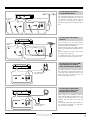
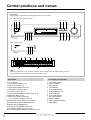
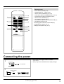
T-4711
FM Stereo / AM Tuner
FM Stereo Tuner
All models except European models
(FM Stereo / AM Tuner)
European model
(FM Stereo Tuner)
T-4711
Instruction Manual
CONTENTS
Features..............................................................................................................................................2
Important safeguards .........................................................................................................................3
Precautions.........................................................................................................................................3
Before using this unit.........................................................................................................................4
System connections ...........................................................................................................................5
Antenna connections..........................................................................................................................6
Control positions and names..............................................................................................................8
Connecting the power ........................................................................................................................9
Receiving stations ............................................................................................................................10
Receiving RDS ................................................................................................................................13
Entering characters ..........................................................................................................................15
Setting the clock .............................................................................................................................16
Using the timer (for remote control only)........................................................................................18
Specifications...................................................................................................................................20
Troubleshooting guide .....................................................................................................................20
T-4711
Thank you
for your purchase of the Onkyo T-4711 Tuner.
Please read this manual thoroughly before making connections and turning power on.
Following the instructions in this manual will enable you to obtain optimum performance and listening enjoyment from your
new Tuner.
Please retain this manual for future reference.
Features
Declaration of Conformity
■ RDS (AF, PS, PTY, TP, RT, CT, TA)
■ 40 FM Random presets / 4 Groups
■ 3 Modes APR (Auto Precision Reception) → IF Band,
High Blend, Mode
■ 4 Groups Memory
■ Dial Tuning Knob
■ FM Cable with 25kHz step Tuning
■ 10-Segment Signal Strength Bar
■ 4 Mode Timer Function (Once, WeekDay, WeekEnd,
Sleep)
■ ACCUCLOCK
■ 7 Remote Compatible
We, ONKYO EUROPE
ELECTRONICS GMBH
INDUSTRIESTRASSE 18/20
82110 GERMERING,
GERMANY
declare in own responsibility, that the ONKYO product described
in this instruction manual is in compliance with the corresponding
technical standards such as EN55013,EN55020,EN60555-2,
EN60065
GERMERING,GERMANY
H. YAMAZOE
ONKYO EUROPE ELECTRONICS GMBH
a.
e.
b.
f.
Remarks:
FM & AM available (For USA, Canada and Asia market)
FM only (For Europe market)
FOR CANADIAN MODEL:
(POUR LE MODELE CANADIEN)
For models having a power cord with a polarized plug.
TO PREVENT ELECTRIC SHOCK, MATCH
WIDE BLADE OF PLUG TO WIDE SLOT, FULLY INSERT.
●
CAUTION:
●
Sur les modèles dont la fiche est polarisée.
ATTENTION: POUR ÉVITER LES CHOCS ÉLECTRIQUES,
INTRODUIRE LA LAME LA PLUS LARGE DE LA FICHE DANS
LA BORNE CORRESPONDANTE DE LA PRISE ET POUSSER
JUSQU’AU FOND.
Memory Preservation
This unit does not require memory preservation batteries. A built-in
memory power back-up system preserves the contents of the memory
during power failures and even when the unit is unplugged. The unit
must be plugged in order to charge the back-up system.
The memory preservation period after the unit has been unplugged varies depending on climate and placement of the unit. On the average,
memory contents are protected over a period of a few weeks after the
last time the unit has been unplugged. This period is shorter when the
unit is exposed to a highly humid climate.
CAUTION
RISK OF ELECTRIC SHOCK
DO NOT OPEN
●
●
2
The lightning flash with arrowhead symbol, within
an equilateral triangle, is intended to alert the user
to the presence of uninsulated “dangerous voltage”
within the product’s enclosure that may be of sufficient magnitude to constitute a risk of electric shock
to persons.
The exclamation point within an equilateral triangle
is intended to alert the user to the presence of
important operating and maintenance (servicing)
instructions in the literature accompanying the
product.
c.
d.
g.
Supplied accessory
a. 1 Remote control
2 Batteries (Size AA, R6, or UM-3)
b. 1 Remote control cable
c. 1 Audio connection cable
d. 1 T-shaped FM antenna
e. 1 AM loop antenna (For models other than European models)
f. 1 75/300 ohm antenna adaptor
(For models other than European models)
g. 1 Conversion plug (Worldwide model only)
“WARNING”
“TO REDUCE THE RISK OF FIRE OR ELECTRIC SHOCK,
DO NOT EXPOSE THIS APPLIANCE TO RAIN OR MOISTURE.”
CAUTION:
“TO REDUCE THE RISK OF ELECTRIC SHOCK, DO NOT
REMOVE COVER (OR BACK). NO USER-SERVICEABLE
PARTS INSIDE. REFER SERVICING TO QUALIFIED SERVICE PERSONNEL.”
Important safeguards
1.
Read Instructions – All the safety and operating instructions should be
read before the appliance is operated.
2.
Retain Instructions – The safety and operating instructions should be
retained for future reference.
3. Heed Warnings – All warnings on the appliance and in the operating
instructions should be adhered to.
4. Follow Instructions – All operating and use instructions should be followed.
5.
Water and Moisture – The appliance should not be used near water –
for example, near a bathtub, washbowl, kitchen sink, laundry tub, in a wet
basement, or near a swimming pool, and the like.
18. Servicing – The user should not attempt to service the appliance beyond
that described in the operating instructions. All other servicing should be
referred to qualified service personnel.
19. Outdoor Antenna Grounding – If an outside antenna is connected to
the receiver, be sure the antenna system is grounded so as to provide some
protection against voltage surges and built up static charges. Article 810 of
the National Electrical Code, ANSI/NFPA 70, provides information with
regard to proper grounding of the mast and supporting structure, grounding of the lead-in wire to an antenna discharge unit, size of grounding conductors, location of the antenna-discharge unit, connection to grounding
electrodes, and requirements for the grounding electrode. See Figure 73.1.
FIGURE 73.1:
EXAMPLE OF ANTENNA GROUNDING AS PER NATIONAL ELECTRICAL CODE
6. Carts and Stands – The appliance should be used only with a cart or
stand that is recommended by the manufacturer.
6A. An appliance and cart combination
should be moved with care. Quick
stops, excessive force, and uneven
surfaces may cause the appliance
and cart combination to overturn.
ANTENNA
LEAD IN
WIRE
GROUND
CLAMP
PORTABLE CART WARNING
ANTENNA
DISCHARGE UNIT
(NEC SECTION 810-20)
ELECTRIC
SERVICE
EQUIPMENT
S3125A
7.
POWER SERVICE GROUNDING
ELECTRODE SYSTEM
(NEC ART 250, PART H)
Wall or Ceiling Mounting – The appliance should be mounted to a
wall or ceiling only as recommended by the manufacturer.
8. Ventilation – The appliance should be situated so that its location or
position does not interfere with its proper ventilation. For example, the
appliance should not be situated on a bed, sofa, rug, or similar surface that
may block the ventilation openings; or if placed in a built-in installation,
such as a book case or cabinet that may impede the flow of air through the
ventilation openings, there should be free space of at least 20 cm and open
up behind the appliance.
9.
Heat – The appliance should be situated away from heat sources such as
radiators, heat registers, stoves, or other appliances (including amplifiers)
that produce heat.
10. Power Sources – The appliance should be connected to a power supply
only of the type described in the operating instructions or as marked on the
appliance.
11. Polarization – If the appliance is provided with a polarized plug having
one blade wider than the other, please read the following information: The
polarization of the plug is a safety feature. The polarized plug will only fit
the outlet one way. If the plug does not fit fully into the outlet, try reversing it. If there is still trouble inserting it, the user should seek the services
of a qualified electrician. Under no circumstances should the user attempt
to defeat the polarization of the plug.
12. Power-Cord Protection – Power-supply cords should be routed so that
they are not likely to be walked on or pinched by items placed upon or
against them, especially near plugs, convenience receptacles, and the point
where they exit from the appliance.
13. Cleaning – The appliance should be cleaned only as recommended by
the manufacturer.
14. Power Lines – An outdoor antenna should be located away from power
lines.
NEC – NATIONAL ELECTRICAL CODE
S2898A
Precautions
1. Warranty Claim
You can find the serial number of the rear panel. In case of warranty
claim, please report this number.
2. Care
From time to time you should wipe the front and rear panels and the
cabinet with a soft cloth. For heavier dirt, dampen a soft cloth in a
weak solution of mild detergent and water, wring it out dry, and wipe
off the dirt. Following this, dry immediately with a clean cloth. Do not
use rough material, thinners, alcohol or other chemical solvents or
cloths since these could damage the finish or remove the panel lettering.
3. Power
WARNING
BEFORE PLUGGING IN THE UNIT FOR THE FIRST TIME,
READ THE FOLLOWING SECTION CAREFULLY.
● Some models are designed for use only with the power supply
voltage of the region where they are sold.
U.S.A. and Canadian models:
European model:
Worldwide model:
15. Nonuse Periods – The power cord of the appliance should be unplugged
from the outlet when left unused for a long period of time.
16. Object and Liquid Entry – Care should be taken so that objects do not
fall and liquids are not spilled into the enclosure through openings.
17. Damage Requiring Service – The appliance should be serviced by
qualified service personnel when:
A. The power-supply cord or the plug has been damaged; or
B. Objects have fallen, or liquid has been spilled into the appliance; or
C. The appliance has been exposed to rain; or
D. The appliance does not appear to operate normally or exhibits a
marked change in performance; or
E. The appliance has been dropped, or the enclosure damaged.
GROUNDING CONDUCTORS
(NEC SECTION 810-21)
GROUND CLAMPS
●
AC 120 V, 60 Hz
AC 230 V, 50 Hz
AC 120 V/220 – 230 V switchable,
50/60 Hz
Voltage Selector (Rear Panel)
Worldwide models are equipped with a voltage selector to conform with local power supplies. Be sure to set this switch to match
the voltage of the power supply in your area before turning the
power button on. (See “Setting the voltage selector and Tuning
step frequency (Worldwide models only)”, P. 4.) Models without a
voltage selector can only be used in areas where the power supply
is the same as that of the unit.
3
Before using this unit
Setting the voltage selector
and Tuning step frequency
(Worldwide models only)
Voltage selector
OUTPUT
ANTENNA
A
FM75Ω
B
1. Determine the proper voltage for your area:
220 – 230 V or 120 V.
2. If the preset voltage is not correct for your
area, insert a screwdriver into the groove
in the switch. Slide the switch all the way
to the right (120 V) or to the left (220 –
230 V), whichever is appropriate.
REMOTE
CONTROL
AM
L
FM STEREO / AM TUNER
MODEL NO. T-4711
RATING: AC120/220-230V
50/60Hz
12W
FREQ. STEP
R
USA
WARNING
2-1,NISSHIN-CHO,NEYAGAWA-SHI,OSAKA,
MADE IN JAPAN
JAPAN
OTHER
VOLTAGE SELECTOR
220-230V
120V
AC OUTLETS
SWITCHED
TOTAL 500W MAX.
AVIS
RISK OF ELECTRIC SHOCK RISQUE DE CHOC ELECTRIQUE
NE PAS OUVRIR
DO NOT OPEN
USA
Tuning step frequency
VOLTAGE SELECTOR
FREQ. STEP
Wooldwide models are equipped with a
switch that controls the AM (9 kHz/10 kHz)
and FM (50 kHz/200 kHz) bands tuning
steps. Please set this switch to match the tuning step frequency in your area.
U.S.A.
: AM 10 kHz, FM 200 kHz
(25 kHz, Fine mode)
Other areas : AM 9 kHz, FM 50 kHz
(25 kHz, Fine mode)
OTHER
120V
220-230V
Please insert the batteries into the remote control according to the illustration.
1
2
+
+
-
3
-
T-4711
Remote control sensor
Inserting the remote control
batteries
Remove the battery compartment cover by
opening it as shown in the illustration. Load
three R6 (UM-3) AA size batteries into the
remote control with the plus (+) and minus
(–) terminals positioned as indicated by the
diagram inside the battery compartment and
close the cover.
● Remove dead batteries immediately to
avoid corrosion damage.
● To avoid potential corrosion damage,
never mix old batteries with new ones.
● The manganese batteries supplied with
this unit have a service life of approximately six months, depending on frequency of usage.
● This unit comes equipped with R6 (UM3) AA manganese batteries, but we recommend that long-life alkaline batteries
LR6 (AM-3) AA be used when replacing
the batteries.
30˚
Using the remote control
30˚
approx. 5m
Remote control
4
The following information will help you get
optimum use from the remote control.
● Place this unit away from direct bright
light, which can prevent proper operation
of the remote control.
● Make sure audio rack doors do not have
coloured glass. If this unit is placed
behind such a door, this may prevent
proper remote control operation.
● Using other remote controls in the same
room as this unit remote control may
cause interference.
System connections
●
●
Do not plug in the power cord until all connections have been made.
On each pair of input or output jacks, the lower jack (marked R) corresponds to the right channel, and the upper jack (marked L) to the left
channel.
Tuning Step Frequency
(See page 4. Worldwide model only)
To wall outlet
Configuration and the number
of outlets may vary depending
on places of destination.
2
OUTPUT
ANTENNA
A
FM75Ω
B
REMOTE
CONTROL
AM
L
FM STEREO / AM TUNER
MODEL NO. T-4711
RATING: AC120/220-230V
50/60Hz
12W
FREQ. STEP
R
USA
WARNING
2-1,NISSHIN-CHO,NEYAGAWA-SHI,OSAKA,
MADE IN JAPAN
JAPAN
OTHER
VOLTAGE SELECTOR
220-230V
120V
AC OUTLETS
SWITCHED
TOTAL 500W MAX.
AVIS
RISK OF ELECTRIC SHOCK RISQUE DE CHOC ELECTRIQUE
NE PAS OUVRIR
DO NOT OPEN
1
Antenna connection
(See pages 6-7.)
L
3
Voltage selector
(See page 4. World
wide model only)
R
Amplifier
1 Connecting the amplifier:
Connect the tuner’s OUTPUT jacks and the amplifier’s INPUT jacks
using the audio connection cable. Refer to the amplifier’s instruction
manual for connections.
2 AC outlets (SWITCHED)
The shape, orientation, the number and total capacity of the AC outlets
may differ according to the model and the area where the unit is purchased. Be careful that other components connected to this unit do not
exceed the capacity that is printed on the rear panel below under the
AC outlets.
When connecting other Integra series components (such as the A9911/9711, DX-7911/7711 or TA-6711), connect the power cords of
those components to this unit’s AC outlets.
The unit may be turned ON or OFF according to the setting of
POWER button, ON or OFF, respectively.
When this unit is used as a timer, the other components that will be
switched on and off should be connected to this unit’s AC outlets.
3 Connections for remote control
When this is connected to an amplifier with the Onkyo 7 jack, you
are able to operate it by pressing the TUNER buttons on the amplifier’s supplied remote control.
Amplifier
A-9711
CD player
T-4711
Cassettedeck
NOTE:
An 7 remote control cable equipped with a 1/8″ (3.5 mm) diameter
miniature two-conductor phone plug is included with this unit and
with every compact disc player and cassette deck with the 7 mark.
5
Antenna connections
Connecting the 300 ohm
ribbon wire to the 75/300 ohm
adaptor (for models other than
European models)
FM/TV
Outdoor
Antenna
300 ohm
ribbon wire
1
2
3
✦
✦ ✦ ✦ ✦
✦
✦✦ ✦ ✦
✦
6 3 6
mm mm mm
Slit B
15mm
1
Wire A
Slit C
2
Loosen the serews and wrap the wire around
these screws, Then tighten the screw with a
screwdriver.
Connecting the coaxial cable
to the 75/300 ohm adaptor
(for models other than
European models)
1. With your fingernail or a small screwdriver, press the stoppers outwardts and
remove the cover.
2. Remove the transformer wire A from slit
B and insert it into slit C.
3. Prepare the coaxial cable as shown in the
diagram. Connect the 75/300 ohm antenna
adaptor to the coaxial cable.
1 Insert the end of the cable.
2 Clamp it in place with pliers.
Directional linkage
Directional linkage
type slitter
To Tuner
Do not use the same antenna for both FM and
TV (or VCR) reception since the FM and TV
(or VCR) signals can interfere with each
other. If you must use a common FM/TV (or
VCR) antenna, use a directional linkage type
splitter.
To TV (or VCR)
Assembling the AM loop
antenna
Assemble the loop antenna as shown in the
illustration.
Insert into the hole.
1
6
2
3
Connecting the antenna cable
1. Press down the lever.
2. Insert wire.
3. Return the lever.
Connecting the enclosed
T-shaped FM antenna
For European
models
For models other than European models
ANTENNA
ANTENNA
FM75Ω
GND
A
A
FM75Ω
B
AM
B
The T-shaped FM antenna is for indoor use
only. Extend the antenna and move it in various directions until the clearest signal is
received. Fix it with push pins or similar in
the position giving the least amount of distortion.
Connecting an FM outdoor
antenna
For European
models
For models other than European models
ANTENNA
ANTENNA
FM75Ω
GND
A
A
FM75Ω
B
AM
B
If the reception is not very clear with the
attached T-shaped FM antenna, the use of an
external antenna is recommended.
Please make sure that you comply with the
following considerations regarding the location.
Keep the antenna away from noise sources
(neon signs, busy roads etc.)
It is dangerous to put it close to power lines,
so keep it well away from power lines, etc.
Connecting the enclosed AM
loop antenna (For models
other than European models)
For models other than
European models
ANTENNA
A
FM75Ω
B
AM
The AM loop antenna is for indoor use only.
Set in the direction and position where you
receive the clearest sound. Put it as far as possible away from the main unit, TV set,
speaker cables and power cord.
Connecting an AM outdoor
antenna (For models other
than European models)
ANTENNA
A
FM75Ω
B
AM
For models other than
European models
When reception is not satisfactory by the use
of the attached AM loop antenna alone, connection of the external antenna is recommended. (Do not remove the AM loop
antenna)
The external antenna will be more effective if
you stretch it horizontally in a high place
above a window or outside.
7
Control positions and names
Front Panel
The button positions may differ slightly depending on the country of purchase.
(For models other than European models)
1 2
3
4
5
6
7
PRESET / TUNING
POWER
DISPLAY
GROUP
SCAN
DIMMER
MEMORY
MODE
STAND-BY/ON
RDS
BAND
IF BAND HI-BLEND
PRESET/
TUNING
RDS
CLEAR
FM STEREO / AM TUNER
8
9 10 11
12 13 14 15
T-4711
PRESET / TUNING
POWER
(For European models)
DISPLAY
GROUP
SCAN
DIMMER
MEMORY
MODE
STAND-BY/ON
RDS
IF BAND HI-BLEND
PRESET/
TUNING
RDS
CLEAR
FM STEREO TUNER
8 10 11
a
b
c
TIMER ANTENNA
RDS
W.DAY
A
B
TP TA
W.END
ONCE
SLEEP SIGNAL STRENGTH
k
d
e
TUNED STEREO MONO
f
g
h
i
j
NORMAL NARROW HI-BLEND AUTO FINE MEMORY
l
NOTE:
If there is a protective film on the surface of the display, which is making it difficult to read the display, remove it.
For more information about buttons, turn to the page number in the [ ].
Front Panel
1.
2.
3.
4.
5.
6.
7.
8.
9.
Power Indicator
Power Button (POWER) [9, 18]
Remote Control Sensor [4]
Display Button (DISPLAY) [12, 14]
Group Button (GROUP) [10, 11]
Scan Button (SCAN) [13, 14]
Preset/Tuning Dial (PRESET/TUNING) [10, 11, 15]
RDS Button (RDS) [13, 14]
Band Selector Button (BAND) [10]
(* Not available on the European model)
10.IF Bandwidth Selector Button (IF BAND) [12]
11.Hi-Blend Selector Button (HI-BLEND) [12]
12.Dimmer Button (DIMMER) [11]
13.Memory Button (MEMORY) [10, 11, 15]
14.Mode Button (MODE) [11, 12, 15, 18, 19]
15.Preset/Tuning Button (PRESET/TUNING) [10, 11, 15]
8
The display and indicator
a.
b.
c.
d.
e.
f.
g.
h.
i.
j.
k.
l.
Timer Mode Indicators
Antenna Indicators
RDS Indicators
Tuned Indicator
Stereo/Mono Indicator
IF-Bandwidth Indicator
Hi-Blend Indicator
Auto Tuning Indicator
Fine Tuning Indicator
Memory Indicator
Signal strentgh level Display
Multi Display
T-4711
Remote control
5
POWER
ANTENNA DIMMER
1
6
1
2
3
GROUP
4
5
6
PRESET
7
8
9
MEMORY
0/10
SCAN
7
2
8
TUNING
3
9
10
TIMER
MODE
4
TIMER
PRESET
ENTER
ADJUST
DISPLAY
REMOTE CONTROL
1. Power Button (POWER) [9, 18]
2. Number Buttons (1 ~ 9, 0/10) [10, 17]
3. Memory Button (MEMORY) [10, 11, 15]
4. Timer preset Buttons (TIMER PRESET) [16, 17, 18]
5. Antenna Selector Button (ANTENNA) [10, 12]
6. Dimmer Button (DIMMER) [11]
7. Group Button (GROUP) [10, 11]
8. Preset memory up/down Buttons (PRESET a/b) [11]
9. Scan Button (SCAN) [13, 14]
10.Tunning up/down Buttons (TUNING a/b) [10]
11.Adjust Button (ADJUST) [16, 17]
12.Display Button (DISPLAY) [12, 14]
11
12
RC-315T
Connecting the power
1. Insert the AC power supply cord into a wall outlet.
“0:00” flashes.
2. When you press the POWER button, the display will light.
1
To a wall outlet
2
Remote control
POWER
POWER
or
9
Receiving stations
2
1 (other than Europe)
6
3 4, 7
6
4
7
T-4711
5, 8
4
5, 8
In order to listen to a radio broadcast, first tune in the radio station,
then set it. The radio station can be selected in two ways: by using the
auto-tuning function or by directly entering the station’s frequency.
When tuning in the radio station, refer to page 12 for more information on how to get the best reception possible.
1
BAND
Tuning the radio and presetting stations
2
Remote control
ANTENNA
ANTENNA
A
B
3
NARROW
TUNED STEREO
ANTENNA
A
PRESET/
TUNING
PRESET → TUNING → CHARACTER
SIGNAL STRENGTH
4
Remote control
PRESET / TUNING
1
2
3
4
5
6
or
Remote
control
TUNING
or
7
8
9
0/10
TUNED STEREO
ANTENNA
A
NARROW HI-BLEND AUTO
SIGNAL STRENGTH
5
Remote control
MEMORY
or
MEMORY
ANTENNA
TUNED STEREO
NARROW HI-BLEND AUTO
MEMORY
A
SIGNAL STRENGTH
6
DISPLAY
Remote control
GROUP
or
SCAN
ANTENNA
A
GROUP
SIGNAL STRENGTH
TUNED STEREO
1. (For models other than European models) Use the BAND button
to select either FM or AM.
2. (When selecting an FM station) Use the ANTENNA button on
the remote control to select the antenna.
3. Press the PRESET/TUNING button until Tuning Mode is
selected.
● With each press of the button, the mode changes one at a time in
the following sequence:
NARROW HI-BLEND AUTO
MEMORY
Continue pressing the PRESET/TUNING button until “TUNING” appears on the display.
● When using the remote control, press the TUNING a/b buttons.
4. Tune in the station.
To tune in a station using the PRESET/TUNING dial:
Turn the PRESET/TUNING dial either clockwise or counterclockwise to begin auto-tuning. Once a station is tuned in, auto-tuning
will stop. When using the remote control, hold down the TUNING
a or b button for more than 0.5 second to begin auto-tuning.
● To select another station, turn the PRESET/TUNING dial again
and the next station will be tuned in.
● If the station’s frequency is weak and auto-tuning is not be able
to tune it in, refer to page 12.
To tune in a station by directly entering the station’s frequency:
Use the number buttons to enter the station’s frequency.
● For example, if the station frequency is 88.10 MHz, press 8
twice, then press 1, and then 0.
● If no radio station can be received at the entered frequency, the
unit will decrease the frequency until the station nearest to the
entered frequency is received.
● If you have accidently entered the wrong frequency, try entering
the correct frequency again.
5. Press the MEMORY button. The MEMORY indicator will
light up and the number of an available preset channel will
flash on the display.
6. Use the GROUP buttons to select the group in which you wish
to preset the station.
You can select from A, B, C or D.
(Continued on page 11)
10