1
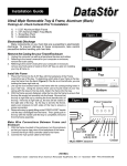
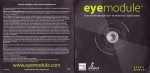
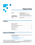
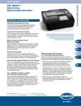
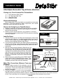
Installation Guide
Ultra2 68pin Removable Tray & Frame, Aluminum
Packing List - Check Contents Prior To Installation:
1)
2)
3)
3)
1 - 5.25" Aluminum 68pin Frame
1 - 3.5" Aluminum 68pin Tray
1 - Screw/Key Pack
1 - Installation Guide
Figure 1
Electrostatic Discharge
Many components on your hard disk are susceptible to electrostatic
discharge. To prevent damage to these components, take careful
precautions before handling your hard disk.
Remove the Casing for your Tower/Enclosure
1. Unplug the computer, as well as all peripheral devices and cables.
2. Referring to the owner's manual for your computer or enclosure,
remove the outer casing.
3. Referring to the owner's manual for your computer or enclosure,
remove any front panel or bezel on the 5.25" bay you plan on installing
your tray & frame in.
Figure 2
Install the Frame
1. Place the Frame into the 5.25" Bay with the backplane of the Frame
toward the rear of the bay. To determine which side of your frame is
the top, view the frame from the back (Figure 2) if the fan is on the
left side, you are holding the frame right side up.
2. Line up the four bracket holes in the frame with the corresponding
holes in your 5.25" bay. Using the screws which can be found inside
of your tray (along with the keys to the tray lock), fasten the frame
into the bay.
3. With the frame securely fastened, slide the tray into
the frame to ensure that the tray fits snugly but smoothly
Figure
into the frame. Be sure that the tray is right side up by
viewing the front (handle side) of the tray. If the tray is
right side up, the lock will be visible on the right side of
the tray. As the tray is slid into the frame, apply even
pressure to both sides of the tray to ensure a proper
connection.
4. Remove the tray by gently lifting on the FORCE-LESSSM
handle until the tray is dislodged from the frame. Then,
gently pull on the tray with the handle until the tray is
completely removed from the frame assembly.
Make Wire Connections Between Frame and
Enclosure
Top
Bottom
3
Power Connector
External
Power LED
External
1
Activity LED
1. With the frame mounted in the enclosure, turn the
2 4 8
enclosure so that you have a clear view of the backplane
of the frame. Connect the 68 pin HDD controller cable
Ground
and the power cable.
68 pin HDD Connector
2. Referring to Figure 3, as well as the documentation
provided with your enclosure, connect the SCSI ID
cables to the five connectors as shown in Figure 3. Please note that not all enclosures come with a connector
for the "8" pin, and this pin is not required for normal operation of the enclosure, tray, or drive.
(MORE)
Installation Guide - DataTrans 68 pin Aluminum Removable Tray&Frame Rev 1.0 - November 1999 - P/N DT51UWSX-A
Install Hard Drive into tray
NOTE: Please reference the documentation that came with your hard
drive for diagrams which show the SCSI pin location(s) on your drive.
1. Open your DataTrans tray by pulling the side of the tray cover away
from the railing and firmly lifting of the cover. If you have difficulty, try
using a pen knife or watchmaker’s screw driver to separate the cover
from the railing. NOTE: You can remove either the top or bottom
cover in this fashion, and the drive can be mounted/accessed with
either or both of the covers removed.
2. Inside your tray you will find several sets of cabling, including a fourpin power connector, a 68pin HDD controller connector, and a block
connector containing seven wires that control SCSI ID and the Activity
LED. (See Figure 4).
3. Referencing the manual that came with your drive, plug the SCSI ID
cable into the appropriate SCSI ID Jumper Block on your drive. Figure
5 provides a nomenclature color diagram for the SCSI ID cabling
inside the tray, and Figure 6 provides an example of how the connector
will fit on the rear jumper block of most drives.
NOTE: A full-color version of Figure 5 is available via a PDF form
on DataStor’s website. Go to www.dstor.com/products and then click
on the “PDF Installation Guides” Link on the bottom of that page.
From there, click the “DT51UWS-A” link to access the appropriate
PDF file.
NOTE: Some drive manufacturers list the 1,2,4,8 SCSI ID signaling
pins as jumper sets 0,1,2 and 3 respectively. If this is the case with
your drive documentation, please note that set 0=1 signal, set 1=2
signal, set 2=4 signal and set 3=8 signal.
4. Plug the four-pin power connector and the 68 pin HDD
controller connector into the drive.
5. Mount the drive into the tray using the four screws provided.
6. Replace the cover by following the reverse procedure for
removing it in step 1.
Install Tray into Frame
1. Set your SCSI ID using the rotational switch located on the bottom
right of the frame (Figure 7). If you are planning on using an external
SCSI ID switch, then set the rotary switch to “0”.
2. Insert your tray into it’s frame as defined in step 3 of “Install the
Frame”. Using the keys provided, insert a key into the lock on the
tray and lock the device into it’s frame. Please note that the drive
will not receive any power until the tray is locked into the frame.
Wiring (Inside Tray)
Figure 4
68pin HDD
Connector Cable
SCSI ID
Drive Activity
Connector
Power
Cable
SCSI Wiring (Inside Tray)
Figure 5
SCSI Signal Chart
Yellow
Orange
Red
Green
Brown
Blue
Purple
=
=
=
=
=
=
=
Figure 6
ID 1 signal
(Jumper
(Jumper
ID 2 signal
ID 4 signal
(Jumper
ID 8 signal
(Jumper
ID Ground
Activity Signal
Activity Ground
set
set
set
set
A0)
A1)
A2)
A3)
Sample SCSI ID
Jumper Configuration
Blue Empty Green Red Orange Yellow
A 3 A2 A 1 A 0
Empty Brown Purple Empty Empty Empty
Replace Enclosure Cover
Figure 7
2345
6789
SCSI Switch
Back of Tray
C
AB D
1. Following the documentation provided by the manufacturer of your enclosure,
replace the cover of the enclosure.
EF0 1
DataStor, 12601 Monarch Street, Garden Grove, CA 92841-3918
Phone (800) 777-6621 / Fax: (714)833-9600 / Web Site: www.dstor.com
Installation Guide - DataTrans 68 pin Aluminum Removable Tray&Frame Rev 1.0 - November 1999 - P/N DT51UWSX-A
Copyright 1999 by DataStor, Inc. All rights reserved. No part of this document may be reproduced in any form without prior written consent from DataStor. The information and specifications in this document are subject to change
without notice. Changes to this document are incorporated in new versions. DataStor, and the DataStor logo are reqistered trademarks of DataStor, Inc. Other trademarks used herein are the property of their respective owners.
This document was printed in the United States Of America.