1
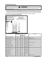
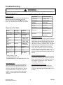
Neptune Front Load Washer⎯
⎯Technical Information
MAH5500B*, MAH55FL*
•
•
Due to possibility of personal injury or property damage, always contact an authorized technician
for servicing or repair of this unit.
Refer to Service Manual 16010061 for detailed installation, operating, testing, troubleshooting, and
disassembly instructions.
! CAUTION
All safety information must be followed as provided in Service Manual 16010061.
.
!
WARNING
To avoid risk of electrical shock, personal injury or death; disconnect power to washer before servicing, unless
testing requires power.
Leaking
• Make sure supply hose connections are not
leaking. Check for rubber gasket damage due to
overtightening.
• Make sure end of drain hose is correctly inserted
and secured to drain facility.
• Avoid overloading which can push the door
partially open.
• Check internal hose connections
• Check tub cover. Remove, reposition and reinstall
the tub cover seal. Seal seam must be at the
top of the tub cover.
Noisy
• Clothes washer should be leveled properly as
outlined in installation instructions.
• Weak floors can cause vibration and walking.
• Check for loose lower front bracket
• Be sure rubber feet are installed on leveling legs.
• Check that the leveling leg lock nuts are
tightened.
• If complaint is a high-pitched noise during fill then
disconnect supply hoses and clean screens.
• Check for proper spring placement of outer tub
support springs.
• Check strut operation.
Display Lights Up When Door Opened
• This is normal behavior.
Tub is completely full of suds
• Run the clothes washer through another complete
cycle using cold water and no more detergent.
• Reduce detergent amount for that specific load size
and soil level. Towel loads have a minimal amount
of soil present and typically create more suds.
• Use high efficiency or low sudsing detergent
specially formulated for front load washers.
• Check for restricted drain system.
• Check for loose wire connections at control board
and pump.
• Check to see if belt fell off motor and pulley.
• Perform Motor and Motor Control Test.
No Tumble
• Washer does not tumble for the first 30 seconds
after the door has been opened for safety purposes.
• Fabric cycles such as DELICATES and HAND
WASH only tumble for a few seconds every 30
seconds.
• Check for loose connections at machine control
board, motor control board and motor.
• Perform Motor and Motor Control Test.
• Washer does not tumble during some drains and
rinse fills.
Wet Clothes
•
Very small clothes loads can cause unbalances
add additional towels.
•
Excessive suds may have been present. Check
for diagnostic code 16.
•
Check unbalance harness connections at all
switches and at Control Board.
No Water Fill
• Check to make sure water supply turned on fully.
• Normal water level is only 2.5 to 5 inches inside
the spinner.
• Check for kinks in inlet hoses.
• Check for clogged inlet screens.
• Visually check hot and cold separately at
dispenser for proper flows.
• Go to No Fill Test page 6.
16025861
1
December 2004
©2004 Maytag Services
Troubleshooting
!
WARNING
To avoid risk of electrical shock, personal injury, or death, disconnect power to washer before servicing,
unless testing requires it.
•
•
Check for restricted drain system.
Perform Motor and Motor Control Test.
•
•
•
Will Not Lock
•
Door not all the way closed.
•
Check electrical connections at lock assembly and
machine control board. Go to Door Lock Test.
•
Will Not Unlock
• Unplug and reconnect the power cord and wait 2
minutes to see if machine unlocks.
• Check for door locked switch circuit to be closed
at machine control. (See board input/output chart)
• Check to make sure belt has not fallen off.
• Check for loose electrical connections at door lock
and at machine control board.
• Perform Motor and Motor Control Test.
•
•
•
Will Not Start
•
Plug cord into live electrical outlet.
•
Check fuse or reset circuit breaker.
•
Push the START/PAUSE button to start the clothes
washer.
•
Close door and push the START/PAUSE button to
start the clothes washer. START/PAUSE LED
should change from flashing to on continuously.
•
Check to see if the washer is in a pause or soak
period in the cycle. Wait briefly and it may start.
• Check for restricted drain system.
Are both faucets on fully?
Make sure temperature selection is correct.
Make sure hoses are connected to correct
faucets and inlet connections. Flush water line
before filling washer.
Check the water heater. It should be set to
deliver a minimum 120°F (49°C) hot water at the
tap. Also check water heater capacity and
recovery rate.
If the water heater is located a long distance from
washer, water line may need to be purged prior to
starting wash cycle.
Disconnect inlet hoses and clean screens.
This washer can sense if the fill hoses have been
reversed between hot and cold. If the fill hoses on
the washer were previously installed incorrectly
and then corrected, the washer will need to be
run through a Hot / Cold cycle. If not resolved,
check for proper resistance on the water valve
thermistor. (See board input/output chart)
Codes Displayed On Console
If owner observes codes on display, see table
below.
Sd = Suds: Machine has detected high level of
suds. The machine will alter its cycle for
this situation. Use an HE detergent or cut
down on the amount of detergent slightly.
This can be more likely on towel loads,
consider HE detergent especially for these
loads.
do = Door is Open: The door of the machine is
open. Please make sure door is fully closed
before starting cycle.
Will Not Drain
• Check for restricted drain system.
•
Check low and high water levels. Go to No Fill test
•
Check for 120 VAC at the pump when a spin cycle
is selected.
Wrong Water Temperature
• Too Hot/Too Cold; since this product uses a low
amount of water, the board regulates the incoming flow to temper the actual temperature of the
water in the tub. This may appear to be
significantly warmer/cooler than expected.
Continued on next page..........
December 2004
©2004 Maytag Services
2
16025861
Troubleshooting
!
WARNING
To avoid risk of electrical shock, personal injury, or death, disconnect power to washer before servicing,
unless testing requires it.
CONSUMER CODES: Cont'd
od = Open the Door: The door has not been
opened since the end of the last cycle. As a
safety check the door must be opened at the
completion of every cycle.
nF = No fill: the machine has tried to fill but cannot.
See No Water Fill.
PF = Power failure: power to the machine has been
lost during the last cycle. This may occur on
start up of a new machine due to factory
testing.
LO = Locked: Door is locked (failed to unlock) - the
machine has repeatedly tried to unlock but
cannot. Push door closed to make sure
nothing from the inside is pressing against
the door which make keep it from unlocking.
FL = Failed to lock: the machine has repeatedly
tried to lock the door but cannot. Make sure
the door is shut completely
nd = No drain - the machine has tried to drain but
cannot.
Lr = Locked Rotor: the machine has repeatedly
tried to turn the motor but cannot.
To Enter
Press K eys
Special
Test/Function
To Exit
Function
Normal
Shows Motor
Torque
Start/Pause
Wri nkle Free
Membrane Pad
C heck
Wai t 5 sec. or
press Off twi ce
Qui ck
Fast Ti me D own Start/Pause
Test
Spi n
Qui ck Spi n Test
Start/Pause
Li ght Soi l
D i splays
Software
Revi si on
Number
Start/Pause
D eli cates
Qui ck Servi ce
C ycle
Start/Pause
Ri nse
Board Output
Test
Start/Pause
Presoak
D i agnosti c
C odes
Start/Pause
Membrane Pad Check Test
While in service mode, pressing the wrinkle free
key will start a membrane pad switch check.
The membrane check involves turning all the embedded LED lights on the membrane pad except
for the wrinkle free key. All the LEDs can be
toggled by pressing the key associated with the
LED. At any point, if there are 10 minutes of inactivity, then this test will exit. Press the off key twice
within 30 seconds to cancel test.
System Diagnostics
SERVICE MODE
The service mode provides service personnel the
ability to verify the operation of the washing machine.
The service mode can be entered in the middle of
any wash cycle. While in the service mode, the
servicer can start a variety of special service tests.
Fast Time Down Test
While in service mode, pressing the quick key
will advance the program to the next wash cycle.
Accessing Service Mode:
Pressing down the delicates and heavy soil keys for
3 seconds places the machine in the service mode.
Motor speed will be displayed when started. To exit
Service Mode, press delicates and heavy soil keys
for 3 seconds again. The following table lists the
various tests available while in the Service Mode,
which can be accessed by pressing the following
keys:
16025861
3
December 2004
©2004 Maytag Services
Troubleshooting
!
WARNING
To avoid risk of electrical shock, personal injury, or death, disconnect power to washer before servicing,
unless testing requires it.
Stage of
Wash Cycle
Advances To
Presoak
End of Presoak
Quick Service Cycle
While in service mode, pressing the delicates key
will start a quick service cycle. This will be a quick
check of all systems.
The following steps will be followed.
1.
Wash
Every 5 Minutes of
Wash Time
Spin/Drain
Every Step of The
Spin Profile
Rinse
End of Rinse
2.
3.
4.
5.
6.
7.
8.
9.
Quick Spin Test
While in service mode, the pressing of spin key shall
start the washer in the quick spin mode.
The up arrow if pressed will advance to the next step.
The right most dot will be turned on as an indication
of failure and stay on until quick service cycle test
has reached the end. Any diagnostic code logged
during this test will result in failure of the test, but will
not necessarily stop the test. While in quick service
cycle, the pressing of the hand wash will suspend
the machine at this step for 30 minutes until the
Hand Wash key is pressed again. All LED’s will
flash on and off while the cycle is suspended, or on
hold.
The following Quick Spin test steps are as follows:
1) Lock the door.
2) Spin to 350 rpm and hold for 6 seconds.
3) Spin to 550 rpm and hold for 6 seconds.
4) Spin to 600 rpm and hold for 6 seconds.
5) Spin to 650 rpm and hold for 6 seconds.
6) Spin to 800 rpm and hold for 6 seconds.
If the Spin key is pressed again during the Quick Spin
test, the current speed will be held indefinitely. Pressing the Spin key again will allow the quick test to
proceed as listed above.
Motor Drive System
To check the system, check the board for proper
output to the motor control. Performing a board
output test does this. Then perform the Motor
Control Board Output Test.
When the washer is in the Service Mode, the speed
will be displayed as a two digit number or a letter/
number.
S p eed R an g e
a) 0-99 rpm
b) 100-999 rpm
December 2004
©2004 Maytag Services
Energize the cold and bleach water valves. Fill to
Low level, then turn bleach and cold off.
Energize the hot and fabric softener water valves. Fill
to high level, then turn all valves off.
Lock the door.
Tumble using 7/3 tumble pattern for 12 sec.
Turn the drain on.
Spin to 800 RPM using default rates.
End spin and coast down.
Unlock the door when the RPM is zero.
Display a ‘PA’ (Passed) on continuously for 10 seconds if no diagnostic codes were logged during this
test.
Motor Control Board Output Test
1. Disconnect power to the washer.
2. Remove the front panel and pull the JP4 Connector
from the motor control board.
3. Reconnect the washer power cord to supply
voltage. Make sure the door is closed.
4. Press delicates and heavy soil keys for 3 seconds to activate Service Mode.
Displayed
0-99 (actual)
Speed / 10
4
16025861
Troubleshooting
!
WARNING
To avoid risk of electrical shock, personal injury, or death, disconnect power to washer before servicing,
unless testing requires it.
5. Access Board Output Test by touching the rinse
key to activate.
6. The door must be locked to access Motor Control Board Output Test. To lock the door press
max extract. Press max extract again stop the
door lock output test once the door is locked.
7. Press stain cycle to start the motor control
output test. This will send 120VAC to the motor
control board. The motor control will immediately
execute a test routine and the motor should run,
rotating the spinner at 50 rpm.
8. If motor does not run;
•
Check for 120 VAC at the motor control board harness. See Figure 1.
If voltage is present, then problem lies with the
motor and motor control system.
•
Check for loose electrical connections at motor and motor control board.
•
Check phase windings of the motor. See Figure 2. If motor windings are good, replace the
motor control board.
•
•
Figure 1
Motor Control Board/JP4 Connector
If voltage is not present;
Check loose electrical connections at machine
control board or broken wires in harness.
Check door actuator switch and related wiring.
Door Lock Test
Placing the washer into the Service Mode and
manually locking and unlocking the
door mechanism through the control panel can
verify the door lock. Note: The relay on the control
board for the door unlock mechanism is disabled if
the motor control board indicates the spinner speed
is > 7 RPM.
1. Place the washer into Service Mode. (See
Service Mode)
2. Advance to the Board Output Test and press
max extract to lock the door. A lock signal
will be sent to the solenoid every second for 10
seconds. If the door does not lock; use a
voltmeter, look for 120VAC, 60 millisecond
pulse to the locking solenoid.
16025861
Figure 2– Schematic – Motor Harness
3. If signal is present, then the door lock solenoid is bad and the door lock mechanism must
be replaced. (Assuming the door was fully
closed.) To stop the signal, press max extract
again.
4. If signal is not present, check electrical
connections at switch or at control board.
Check for proper outputs from the control board
at Conn P1(1) and Neutral leg of power cord. If
voltage is present, fix electrical connections or
change wire harness. If no voltage is found, go
to P8(4) and Neutral on power cord to verify
120VAC coming into the board. If voltage is not
present check the door actuator switch. (make
sure door is closed.) If voltage is present,
change machine control board.
5
December 2004
©2004 Maytag Services
Troubleshooting
!
WARNING
To avoid risk of electrical shock, personal injury, or death, disconnect power to washer before servicing,
unless testing requires it.
5. Advance to the Board Output Test and press
extra rinse to unlock the door. An unlock
signal will be sent to the solenoid every second
for 10 seconds.
If the door does not lock, use a voltmeter, look
for 120VAC, 60 millisecond pulse to the locking
solenoid.
If signal is present, then the door lock solenoid is bad and the door lock mechanism must
be replaced. To stop the signal, press extra
rinse again.
If signal is not present, check electrical
connections at switch or at control board.
Check for proper outputs from the control board
at Conn P8(3) and Neutral leg of power cord. If
voltage is present, fix electrical connections or
change wire harness. If no voltage is found, go
to P8(4) and Neutral on power cord to verify
120VAC coming into the board. If voltage is not
present check the door actuator switch. (make
sure door is closed.) If voltage is present,
change machine control board.
If voltage is present at the machine control board,
check voltage at pressure switch between BU and
BR . If voltage present at
pressure switch, replace pressure switch. If voltage is not present at
pressure switch, check or replace harness. If no
voltage is present at the Machine control board,
replace the machine control board.
7. "_0" indicates the washer is empty: If empty,
press the wrinkle free key to check the high water level.
8. "--1" indicates full. If full, check the high water
level input at the machine control board by
reading 120 VAC voltage between P1(4) and
Neutral P6(2). If120 VAC is not present at the
machine control board, check continuity at
pressure switch across GY and YL. If no
continuity, replace pressure switch. If continuity,
check door switch and harness to pressure switch
and harness from pressure switch to Machine
control board. If 120 VAC is present at the
Machine control board, replace the machine
control board.
9. "--0" indicates empty. If empty, exit board input
test mode by pressing the start/pause key. Then
enter board output test mode by pressing the rinse
key.
10. Turn the cold water valve on by pressing the wrinkle
free key. Check for cold water flow at the dispenser.
If no cold water flow, check the cold water valve for
120 VAC between BU and WH. If 120 VAC is
present at the cold valve, replace the water valve. If
120 VAC is not present at the cold valve, check for
120 VAC at the machine control board between
P1(3) and Neutral. If 120 VAC is present at the
machine control board, check or replace the
harness. If 120 VAC is not present at the machine
control board, replace the machine control board.
If cold water flows, turn the cold valve off by pressing
the wrinkle free button.
No Fill Test
1. Close the door and start a spin cycle to drain all
water from the washer to reset the pressure switch.
2. Press Off and open door to verify all water is removed from the washer. If water still present, go
to Will Not Drain diagnostics.
3. If water is drained out, close the door and go to
Service Mode, press delicates and heavy soils
keys for 3 seconds. If it is likely to need access to
the water valve for voltage checks, consider raising
the top cover now and close the door so that the
following steps will not need to be repeated.
4. While in service mode, press the hand wash key
places the washer into the Board Input test.
5. Check the lower water level by pressing the hand
wash key.
6. "_1" indicates the washer is full. If full, check the
lower water level input at the machine control board
by reading DC voltage between P4(4) and P4(8).
December 2004
©2004 Maytag Services
6
16025861
Troubleshooting
!
WARNING
To avoid risk of electrical shock, personal injury, or death, disconnect power to washer before servicing,
unless testing requires it.
11.Turn the hot on by pressing the cotton sturdy key. Check for hot water flow at the dispenser. If no hot water
flow, check the hot water valve for 120 VAC between OR and WH. If 120 VAC is present at the hot valve, replace
the water valve. If 120 VAC is not present at the hot valve, check for 120 VAC at the machine control board
between P1(2) and Neutral. If 120 VAC is present at the machine control board, check or replace the harness.
If 120 VAC is not present at the machine control board, replace the machine control board.
Machine Control Board INPUT/OUTPUT
Drain Pump (DP)
Motor (MTR)
Door Unlock Solenoid (DUL)
Door Switch (DS)
N
L1
+24 Volts (24V)
Unbalanced Switches(UB)
Mtr Control Signal Common (Comm)
Motor Control Tach (Tach)
Torque PWM (PWM)
+24 Volts (24V)
Door Lock Actuator Switch (DLS)
Valve Thermistor (WT)
Valve Thermistor (WT)
Lower Wash Level Sense (LWL)
Door Lock Solenoid ( Lock or DL)
Wiring Harness
Hot Water Valve (HWV)
Cold Water Valve (CWV)
Connections
Bleach Water Valve ( BWV)
Letters in parenthesis designate
Softener Water Valve (SWV)
markings on the Control Board
High Level Sense (HWL)
P4
Description
P3
Connector/
Pin Number
Voltage
Comments
Bleach water valve output
P1(4)
Reference
To
Connector/
Pin Number
P6(2)
Cold water valve output
P1(3)
P6(2)
120 VAC
500-1K ohms
Door Lock output
P1(1)
P6(2)
120 VAC
60 millisecond pulse
Door lock switch input
P4(5)
P4(4)
24 VDC
120 VAC
Door switch input
P8(4)
P6(2)
120 VAC
Door unlock output
P8(3)
P6(2)
120 VAC
Drain pump output
P8(1)
P6(2)
120 VAC
High water level - input
P1(6)
P6(2)
120 VAC
Hot water valve output
P1(2)
P6(2)
120 VAC
L1- machine control board
P6(1)
P6(2)
120 VAC
L1- motor control
P8(2)
P6(2)
120 VAC
Lower water level - input
P4(8)
P4(4)
24 VDC
Motor control tach
P4(2)
P4(4)
24 VDC
Neutral (120 VAC)
P6(2)
500 - 1K ohms
Neutral
Unbalance input
P3(2)
P4(4)
24 VDC
Softener water valve
P1(5)
P6(2)
120 VAC
Torque PWM
P4(3)
P4(4)
24 VDC
Water valve thermistor
P4(6)
P4(7)
16025861
60 millisecond pulse
7
(10K-85K ohms)
December 2004
©2004 Maytag Services
Troubleshooting
!
WARNING
To avoid risk of electrical shock, personal injury, or death, disconnect power to washer before servicing,
unless testing requires it.
Board Output Test Table
Board Input Test
While in service mode, pressing the hand wash key
places the washer into the Board Input Test.
This test will turn on a specified input after a key
press. All output will be turned off after 10 minutes.
Board Input Test Table
**
Action
Press Key
Feedback
Door Position
cotton/sturdy
dO Open
Latch Position
delicates
LO Unlocked
L l Locked
High Water
Level
wrinkle free
--
Low Water
Level
hand wash
_O Below Level
_ l Above Level
Unbalance
Circuit
temp down
uO Balanced
u l Unbalanced
--
O Below Level
l Above Level
Water Inlet Temp temp up
Degrees oF
Vibration Signal spin
0-225**
Brown out
rinse
0-225**
Accelerometer
circuit
quick
PA = Passes
FA = Fails
Function Performed
Cotton/sturdy
Hot Water Valve
Wrinkle Free
Cold Water Valve
Delicates
Bleach Valve
Hand Wash
Fabric Softener Valve
Presoak
Drain Pump
Stain Cycle
Motor Control
Extra Rinse
Unlock Door (Sends a
pulse every second for
10 seconds)
Max Extract
Lock Door (Sends a
pulse every second for
10 seconds)
DIAGNOSTIC CODES:
When a problem with the wash system is detected
a diagnostic code is assigned and logged into the
control board memory with the last cycle count at
which it occurred. An assigned diagnostic code
indicates the washer must be serviced. The control
board will allow as many diagnostics as possible
for the machine to continue running. In some
cases, when the washer shuts down, something
shall be displayed on the display until the consumer selects the off key. See the table for specific
actions or references to where the proper action is
defined.
Accessing Diagnostic Codes
After the machine is in the service mode, pressing
presoak key will display a ‘d’ and turn the LED on
above the presoak key. The diagnostic codes can
be viewed by using the arrow keys. The down
arrow will go down the list.
Two digit display = 0-99;
plus max extract LED =100,
plus max extract LED and extra rinse LED = 200.
Board Output Test
While in service mode, pressing the rinse key
places the washer into the Board Output Test.
This test will turn on a specified output after a
key press. All outputs will continue on until the
key is pressed again, or it will turn off after 10
minutes. Note, to check the fabric and bleach
valves, you must turn on the hot or cold water
valves first.
December 2004
©2004 Maytag Services
Key Pressed:
Clearing Diagnostic Code List
While viewing the diagnostic code listing, the
diagnostic code list can be cleared from memory
by pressing the heavy soil and presoak keys for 3
seconds.
8
16025861
Troubleshooting
!
WARNING
To avoid risk of electrical shock, personal injury, or death, disconnect power to washer before servicing,
unless testing requires it.
Number of Cycles Since Code Assigned
While the Diagnostic code is displayed, if the
cotton/sturdy key is pressed and held, the machine
shall display the number of cycles ago the code
occurred while the key is held. Also, while this key
is being held, the key will turn on the LED. When
this key is let up, then the code is again displayed.
If there are no codes available, ‘- -‘ will be displayed
while this key is pressed. If the code is over 99
cycles ago, then ‘- -‘ will be displayed.
DIAGNOSTIC CODES:
Diag.
Description
Code
01
No drain
Trigger
Action to be Taken
The water level fails to Will display "nd"
drop below the low
Go to "Will Not Drain" page 3.
water level in final spin
02
The door fails to
unlock
Door failed to unlock
after 11 attempts
Will display "LO"
Go to "Will Not Unlock" page 3.
03
No fill
Continuous fill of 12
minutes.
Will display "nF"
Go to "No Water Fill" page 2.
04
The door fails to
lock
Door failed to lock
after 11 attempts
Will display "FL"
Go to "Will Not Unlock" page 3..
05
Continuous
unbalanced circuit
(During spin only)
See section for
unbalanced loads.
Go to "Wet Clothes" page 2.
06
Locked rotor
Motor not turning after
10 consecutive retry
attempts
Will display "Lr"
Go to "Motor Control Board Output
Test" page 5.
07
(Not Used)
16025861
9
December 2004
©2004 Maytag Services
Troubleshooting
!
WARNING
To avoid risk of electrical shock, personal injury, or death, disconnect power to washer before servicing,
unless testing requires it.
Diag.
Code
08
Description
Water sensor level
fault
09
(Not Used)
10
Low rpm
unbalanced load
11
Non-volatile
memory error
Trigger
Action to be Taken
The low water level is Go to "No Water Fill Test" page 2.
not satisfied before the
high water level
contacts are opened
in the pressure switch
Never reached 400
rpm due to an
unbalanced load
Difficulty in reading
memory
Go to "Wet Clothes" page 2.
1. Go to "Clearing Diagnostic Code "
page 9.
2. Unplug and replug in power cord
washer at power supply outlet
3. If a condition still exists, replace
machine control board.
12-14 (Not Used)
15
Stuck key
16
High speed not
achieved due to
high motor torque
17
Door actuator
switch was not
seen open since
the last final spin
18
Door lock switch
seen open during
cycle
December 2004
©2004 Maytag Services
A key is sensed to be
pressed for more than
75 seconds, the key
shall be assumed to
be stuck
Speed never went over
400 rpm during a main
wash cycle because
the maximum torque
was seen for too long
The door has not been
opened after a
complete wash cycle.
Door lock switch is
read as open with
motor running
10
Replace console/membrane switch.
Go to "Wet Clothes" page 2.
Will display "od"
Check for:
- Customer may have tried to repeat
wash cycle without opening door
-Go to "Door Lock Test" page 6.
- Clear the diagnostic code, page 9.
recheck;
"Go to "Door Lock Test" page 6.
16025861
Troubleshooting
!
WARNING
To avoid risk of electrical shock, personal injury, or death, disconnect power to washer before servicing,
unless testing requires it.
Diag.Description
Code
19
Door lock sense or
motor control relay
failed
Trigger
Action to be Taken
Door lock sense switch See list for diagnostic code 18
on machine control
board is read as open
with motor running
20
Door switch input
seen open during
cycle
Door switch is open
Go to "Door Lock Test", page 6.
21
Door sense switch
failed on machine
control board
Go to "Door Lock Test", page 6.
22
Door switch seen
open during cycle
23
Door failed to
unlock
24
Motor over speed
Door sense switch is
read as open and the
door locked switch is
read as locked
Door switch is read as
open and the door
locked switch is read
as locked
Door lock is locked
and a user tries to
start a cycle
Motor tach signal is
seen at maximum
speed
Tach signal exists
without torque
commanded.
Abnormal high/low
temperature or ohm
resistance seen
Go to "Wrong Water Temperature" page
3.
25
Motor tach signal
exists without
motor running
26-27 (Not Used)
28
Valve thermistor
failure
16025861
11
Go to "Door Lock Test", page 6.
Go to "Will Not Unlock" page 3.
- Replace motor control board
- Replace motor control board
December 2004
©2004 Maytag Services
Wiring Diagram
!
WARNING
To avoid risk of electrical shock, personal injury, or death, disconnect power to washer before servicing,
unless testing requires it.
December 2004
©2004 Maytag Services
12
16025861
Traduction du schéma/de l'esquisse de l'anglais au français
14 PIN UPPER TO LOWER HARNESS
CONNECTOR
AUGER MOTOR (MTR)
AUGER MOTOR HARNESS
AUTOMATIC ICE MAKER
BASE PAN GROUND
BLACK (BK)
BLEACH VALVE
BLOWER MOTOR
BLUE (BU)
BOARD MOUNTED RELAYS
BODY
BOOSTER COIL
BROWN (BR)
CABINET HARNESS
CAP
CAPACITOR
CAVITY HEATER
CIRCUIT BOARD
CIRCUIT DIAGRAM
COLD VALVE
COM
COMP GROUND
CONDENSER
CONDENSER FAN MOTOR
CONTROL BOARD
CONTROL BOARD AND DISPLAY
CONTROL CIRCUIT
CONTROL CIRCUIT DIAGRAM
CONTROL HARNESS
DAMPER
DEFROST TERMINATOR
DISPENSER
DISPLAY HARNESS
DISPLAY PCB
DOOR CLOSE SWITCH
DOOR CLOSED
DOOR HINGE
DOOR LOCK SOLENOID OUTPUT
DOOR LOCK SWITCH
DOOR LOCK SWITCH INPUT
DOOR SOLENOID
DOOR SWITCH
DOOR UNLOCK SOLENOID OUTPUT
DRAIN PUMP
DRIP TRAY
DRYER MOTOR
ELECTRONIC CONTROL
ELECTRONIC SWITCH
EMI FILTER
EVAPORATOR FAN
FA
FABRIC SOFTENER
FF THERMISTOR
FLAT WIRE
FLOAT SWITCH
FOUNTAIN DISPLAY
FOUNTAIN LIGHT
FRONT WEIGHT DISPLACEMENT
SWITCH
FUSE
FUSE BLOCK
FZ LITE SWITCH
FZ. DOOR HARNESS
16025861
©2004 Maytag Services
CONNECTEUR DE LIAISON DE
FAISCEAUX SUPÉRIEUR À
INFÉRIEUR À 14 BROCHES
MOTEUR POUR AGITATEUR (MTR)
FAISCEAU DE MOTEUR
D’AGITATEUR
MACHINE À GLAÇONS
AUTOMATIQUE
TERRE DU PLATEAU
NOIR (NR)
ROBINET D’EAU DE JAVEL
MOTEUR DU VENTILATEUR
BLEU (BL)
RELAIS MONTÉS SUR TABLEAU
BÂTI
BOBINE DE SURTENSION
MARRON (MA)
FAISCEAU D’ARMOIRE
COND
CONDENSATEUR
CHAUFFERETTE À LOBE
CARTE DE CIRCUITS IMPRIMÉS
SCHÉMA DU CIRCUIT
ROBINET D'EAU FROIDE
COM
TERRE DE CIRCUIT DE
COMPENSATION
CONDENSATEUR
MOTEUR DE VENTILATEUR DU
CONDENSEUR
TABLEAU DE COMMANDE
TABLEAU DE COMMANDE ET
AFFICHEUR
CIRCUIT DE COMMANDE
SCHÉMA DU CIRCUIT DE
COMMANDE
FAISCEAU DE COMMANDE
REGISTRE
TERM INATEUR DE DÉGIVRAGE
DISTRIBUTRICE
FAISCEAU D’AFFICHEUR
AFFICHEUR PCB
CONTACTEUR DE PORTE FERMÉE
PORTE FERMÉE
CHARNIÈRE DE PORTE
SORTIE SOLÉNOÏDE DE
VERROUILLAGE DE PORTE
CONTACTEUR DE PORTE
VERROUILLÉE
ENTRÉE DE CONTACTEUR DE
VERROUILLAGE DE PORTE
SOLÉNOÏDE DE PORTE
CONTACTEUR DE PORTE
SORTIE SOLÉNOÏDE DE
DÉVERROUILLAGE DE PORTE
POMPE D’ÉVACUATION
PLATEAU D’ÉGOUTTOIR
MOTEUR DE SÉCHEUSE
COMMANDE ÉLECTRONIQUE
CONTACTEUR ÉLECTRONIQUE
FILTRE EMI
VENTILATEUR ÉVAPORATEUR
FA
ADOUCISSEUR DE TISSUS
THERMISTANCE À BASCULE
FIL MÉPLAT
CONTACTEUR À FLOTTEUR
AFFICHEUR DE FONTAINE
VOYANT DE FONTAINE
CONTACTEUR DE DÉSÉQUILIBRE
DU POIDS AVANT
FUSIBLE
BLOC FUSIBLES
CONTACTEUR DE VOYANT DU
CONGÉLATEUR
FAISCEAU DE PORTE DU
CONGÉLATEUR
GAS HEATER
GRAY (GY)
GREEN (GN)
HEAT SINK
HEATER
HEATER RELAY
HEATER WITH STEAMER ASSEMBLY
HIGH HEAT
HIGH LEVEL SENSE
HIGH T'STAT
HIGH VOLTAGE
HOLDING COIL
HOT VALVE
HV PCB HARNESS
IGNITOR
IM VALVE
INERTIAL BALANCE SWITCH
INPUT
INTERLOCK SWITCH
INTERLOCK SWITCH SCHEMATIC
LAMP
LID LOCKED INPUT
LINE FILTER
LOCKING
LOGIC BOARD
LOW HEAT
LOW VOLTAGE
LOWER DRYER SIDE
LOWER FREEZER LIGHT
LOWER HARNESS CONNECTOR
LOWER LEVEL SENSOR
MACHINE CONTROL
MAG TCO
MAGNETRON
MAIN
MAIN VALVE
MC HARNESS
MEMBRANE SWITCHES
MICROFARAD
MONITOR SWITCH
MOTOR
MOTOR CAPACITOR
MOTOR CONTROL
MOTOR CONTROL SIGNAL COMMON
MOTOR CONTROL TACH
MOTOR HARNESS CONNECTIONS
MOTORIZED DAMPER
NEUTRAL
NOISE FILTER
OPTION
ORANGE (OR)
OUT OF BALANCE
OUTPUT
OVEN LIGHT
OVEN THERMAL LINK
OVERLOAD
OVERLOAD PTC RELAY
PCB CONTROL
PINK (PK)
POWER
POWER CORD
POWER RELAY
POWER TRANSFORMER
PRE VALVE (BLEACH)
13
1
CHAUFFERETTE AU GAZ
GRIS (GR)
VERT (VE)
DISSIPATEUR DE CHALEUR
CHAUFFERETTE
RELAIS DE CHAUFFERETTE
ENSEMBLE CHAUFFERETTE /
ÉTUVEUSE
TEMPÉRATURE ÉLEVÉE
CAPTEUR DE HAUT NIVEAU
THERMOSTAT SUR HAUT
HAUTE TENSION
BOBINE DE MAINTIEN
ROBINET D’EAU CHAUDE
FAISCEAU HT PCB
DISPOSITIF D’ALLUMAGE
ROBINET DE MACHINE À GLAÇONS
CONTACTEUR D’ÉQUILIBREUR
D’INERTIE
ENTRÉE
INTERRUPTEUR D’INTERDICTION
SCHEMA INTERRUPTEUR
D’INTERDICTION
LAMPE
ENTRÉE DE COUVERCLE
VERROUILLÉ
FILTRE DE LIGNE
VERROUILLAGE
CARTE LOGIQUE
TEMPÉRATURE BASSE
BASSE TENSION
CÔTÉ INFÉRIEUR DE LA SÉCHEUSE
VOYANT DU CONGÉLATEUR
INFÉRIEUR
CONNECTEUR DE FAISCEAU
INFÉRIEUR
CAPTEUR DE NIVEAU INFÉRIEUR
COMMANDE DE MACHINE
MAG TCO
MAGNÉTRON
PRINCIPAL
ROBINET PRINCIPAL
FAISCEAU DE COMPARTIMENT DE
MACHINE
CONTACTEURS À MEMBRANE
MICROFARAD
INTERRUPTEUR DE SURVEILLANCE
MOTEUR
CONDENSATEUR DU MOTEUR
COMMANDE DE MOTEUR
COMMUN DU SIGNAL DE
COMMANDE DE MOTEUR
TACHYMÈTRE DE COMMANDE DE
MOTEUR
CONNEXIONS DU FAISCEAU DU
MOTEUR
REGISTRE À ENTRAÎNEMENT
MÉCANIQUE
NEUTRE
FILTRE ANTIPARASITES
OPTION
ORANGE (OR)
DÉSÉQUILIBRE
SORTIE
LUMIÈRE DU FOUR
LIAISON THERMIQUE DU FOUR
SURCHARGE
RELAIS CTP DE SURCHARGE
COMMANDE PCB
ROSE (RO)
ALIMENTATION
CORDON D’ALIMENTATION
RELAIS D’ALIMENTATION
TRANSFORMATEUR
D’ALIMENTATION
PRÉ-LAVAGE (JAVEL)
December 2004
©2004 Maytag Services
Technical Sheet Supplement
Traduction du schéma/de l'esquisse de l'anglais au français
PRESSURE SWITCH
PRESSURE VALVE
PRIMARY INTERLOCK SWITCH
REACTOR
RECTIFIER
RED (RD)
REF LIGHTS HARNESS
REF. DOOR HARNESS
RELAY 1
RELAY 2
RELAY BOARD
RES
RESISTANCE
RIBBED
ROTOR
RUN CAP
SCHEMATIC CONDITIONS: DOOR
OPEN
SECOND COIL
SECONDARY INTERLOCK SWITCH
SENSOR BARS
SHAKER ASSEMBLY
SNUBBER
SOFTENER VALVE
SOLENOID
SPORTS FILL SWITCH
STATOR
SUPER COOL
SUPPLY LINE
SYSTEM RELAY
TAN (TN)
TCO (MAG)
MANOSTAT
SOUPAPE DE PRESSION
INTERRUPTEUR D’INTERDICTION
PRIMAIRE
BOBINE DE RÉACTANCE
REDRESSEUR
ROUGE (RO)
FAISCEAU DE VOYANTS DU
RÉFRIGÉRATEUR
FAISCEAU DE PORTE DU
RÉFRIGÉRATEUR
RELAIS 1
RELAIS 2
CARTE DE RELAIS
RÉS
RÉSISTANCE
CANNELÉ
ROTOR
CONDENSATEUR DE MARCHE
CONDITIONS DU SCHÉMA : PORTE
OUVERTE
DEUXIÈME BOBINE
INTERDICTION D’INTERDICTION
SECONDAIRE
BARRES DE CAPTEUR
ENSEMBLE D'AGITATEUR
AMORTISSEUR
ROBI NET D’ADOUCISSEUR
SOLÉNOÏDE
INTERRUPTEUR DE REMPLISSAGE
UNIPOLAIRE - UNIDIRECTIONNEL
STATOR
TRÈS FRAIS
CONDUITE D’ALIMENTATION
RELAIS DE SYSTÈME
BRONZE (BR)
TCO (MAG)
December 2004
©2004 Maytag Services
Technical Sheet Supplement
TERM BLOCK
TERMINAL BOX
THERMAL FUSE
TOROID
TORQUE
TOUCH CONTROL
TOUCH PAD
TRIAC
TUB DISPLACEMENT SWITCH
TUB SENSOR
TUB SHIELD
TUBE LIGHT
TUMBLE DRYER SENSOR
TUMBLER MOTOR
UPPER DRYER SIDE
UPPER FREEZER LIGHT
UPPER HARNESS CONNECTOR
VENT
VIOLET (VT)
VOLTS
WASH HEATER
WASH MOTOR
WATER SENSOR
WHITE (WH)
WIRE CODE
WIRES SHOWN FROM INSERTION
SIDE
WIRING COLOR CODE
WIRING DIAGRAM
WIRING DIAGRAM PART NO.
YELLOW (YL)
BORNIER
BOÎTIER DE CONNEXIONS
FUSIBLE THERMIQUE
TORE
COUPLE
COMMANDE TACTILE
PAVÉ TACTILE
TRIAC
CONTACTEUR DE DÉPLACEMENT
DE CUVE
CAPTEUR DE CUVE
PROTECTEUR DE CUVE
LAMPE TUBE
CAPTEUR DE TAMBOUR DE
SÉCHEUSE
MOTEUR DE TAMBOUR
CÔTÉ SUPÉRIEUR DE LA
SÉCHEUSE
VOYANT DU CONGÉLATEUR
SUPÉRIEUR
CONNECTEUR DU FAISCEAU
SUPÉRIEUR
ÉVENT
VIOLET (VT)
VOLTS
CHAUFFERETTE DE LAVAGE
MOTEUR DE LAVAGE
CAPTEUR D’EAU
BLANC (BL)
CODAGE DES CONDUCTEURS
FILS MONTRÉS DU CÔTÉ
INSERTION
CODE COULEURS DU CÂBLAGE
SCHÉMA DE CÂBLAGE
RÉ F. SCHÉMA DE CÂBLAGE
JAUNE (JA)
14
16025861
2
©2004 Maytag Services