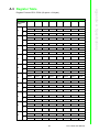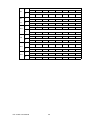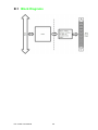
1
User Manual PCI-1752U 64-ch Isolated Digital Output PCI Card Copyright The documentation and the software included with this product are copyrighted 2015 by Advantech Co., Ltd. All rights are reserved. Advantech Co., Ltd. reserves the right to make improvements in the products described in this manual at any time without notice. No part of this manual may be reproduced, copied, translated or transmitted in any form or by any means without the prior written permission of Advantech Co., Ltd. Information provided in this manual is intended to be accurate and reliable. However, Advantech Co., Ltd. assumes no responsibility for its use, nor for any infringements of the rights of third parties, which may result from its use. Acknowledgements Intel and Pentium are trademarks of Intel Corporation. Microsoft Windows and MS-DOS are registered trademarks of Microsoft Corp. All other product names or trademarks are properties of their respective owners. Product Warranty (2 years) Advantech warrants to you, the original purchaser, that each of its products will be free from defects in materials and workmanship for two years from the date of purchase. This warranty does not apply to any products which have been repaired or altered by persons other than repair personnel authorized by Advantech, or which have been subject to misuse, abuse, accident or improper installation. Advantech assumes no liability under the terms of this warranty as a consequence of such events. Because of Advantech’s high quality-control standards and rigorous testing, most of our customers never need to use our repair service. If an Advantech product is defective, it will be repaired or replaced at no charge during the warranty period. For outof-warranty repairs, you will be billed according to the cost of replacement materials, service time and freight. Please consult your dealer for more details. If you think you have a defective product, follow these steps: 1. Collect all the information about the problem encountered. (For example, CPU speed, Advantech products used, other hardware and software used, etc.) Note anything abnormal and list any onscreen messages you get when the problem occurs. 2. Call your dealer and describe the problem. Please have your manual, product, and any helpful information readily available. 3. If your product is diagnosed as defective, obtain an RMA (return merchandize authorization) number from your dealer. This allows us to process your return more quickly. 4. Carefully pack the defective product, a fully-completed Repair and Replacement Order Card and a photocopy proof of purchase date (such as your sales receipt) in a shippable container. A product returned without proof of the purchase date is not eligible for warranty service. 5. Write the RMA number visibly on the outside of the package and ship it prepaid to your dealer. PCI-1752U User Manual Part No. XXXXXXXXXX Edition 1 Printed in Taiwan July 2015 ii Declaration of Conformity CE This product has passed the CE test for environmental specifications when shielded cables are used for external wiring. We recommend the use of shielded cables. This kind of cable is available from Advantech. Please contact your local supplier for ordering information. FCC Class A Note: This equipment has been tested and found to comply with the limits for a Class A digital device, pursuant to part 15 of the FCC Rules. These limits are designed to provide reasonable protection against harmful interference when the equipment is operated in a commercial environment. This equipment generates, uses, and can radiate radio frequency energy and, if not installed and used in accordance with the instruction manual, may cause harmful interference to radio communications. Operation of this equipment in a residential area is likely to cause harmful interference in which case the user will be required to correct the interference at his own expense. Technical Support and Assistance 1. 2. Visit the Advantech web site at www.advantech.com/support where you can find the latest information about the product. Contact your distributor, sales representative, or Advantech's customer service center for technical support if you need additional assistance. Please have the following information ready before you call: – Product name and serial number – Description of your peripheral attachments – Description of your software (operating system, version, application software, etc.) – A complete description of the problem – The exact wording of any error messages Packing List Before setting up the system, check that the items listed below are included and in good condition. If any item does not accord with the table, please contact your dealer immediately. PCI-1752U DAQ Card StartUp or User Manual Companion DVD-ROM with DAQNavi drivers included iii PCI-1752U User Manual Safety Precaution - Static Electricity Follow these simple precautions to protect yourself from harm and the products from damage. To avoid electrical shock, always disconnect the power from your PC chassis before you work on it. Don't touch any components on the CPU card or other cards while the PC is on. Disconnect power before making any configuration changes. The sudden rush of power as you connect a jumper or install a card may damage sensitive electronic components. PCI-1752U User Manual iv Contents Chapter 1 Introduction..........................................1 1.1 1.2 1.3 1.4 1.7 Introduction ............................................................................................... 2 Features .................................................................................................... 2 Applications............................................................................................... 3 Installation Guide ...................................................................................... 3 Figure 1.1 Installation Flow Chart ................................................ 4 Software Overview .................................................................................... 4 DAQNavi Device Driver Programming Roadmap ..................................... 5 1.6.1 Programming Tools....................................................................... 5 1.6.2 Programming with DAQNavi Device Drivers Function Library...... 6 1.6.3 Troubleshooting DAQNavi Device Drivers Error........................... 6 Accessories............................................................................................... 6 2 Installation............................................9 2.1 2.2 2.3 Unpacking ............................................................................................... 10 Hardware Installation .............................................................................. 11 Device Setup & Configuration ................................................................. 12 Figure 2.1 The Device Setting of PCI-1752U ............................ 12 Figure 2.2 The Digital I/O Setting Page ..................................... 13 Figure 2.3 The Device Testing of PCI-1752U............................ 14 3 Signal Connections ...........................15 3.1 3.2 3.4 Overview ................................................................................................. 16 Switch and Jumper Settings.................................................................... 16 Figure 3.1 Connector and Switch Locations .............................. 16 3.2.1 Board ID (SW1)........................................................................... 17 Table 3.1: Board ID Setting (SW1) ............................................ 17 3.2.2 Power On Configuration(JP1) ..................................................... 18 Table 3.2: Power on configuration after hot reset (JP1) ............ 18 3.2.3 Channel-Freeze Function (JP2).................................................. 18 Table 3.3: Dry/Wet Contact of Channel-Freeze Function (JP2) 18 Signal Connections ................................................................................. 19 Figure 3.2 I/O Connector Pin Assignments ............................... 19 3.3.1 I/O Connector Pin Definition ....................................................... 20 Table 3.4: I/O Connector Signal Descriptions ........................... 20 3.3.2 Isolated Digital Output................................................................. 20 Figure 3.3 Isolated Digital Output Connection ........................... 20 3.3.3 Channel-Freeze Function ........................................................... 21 Figure 3.4 Wiring in dry contact input mode .............................. 21 Figure 3.5 Wiring in wet contact input mode.............................. 21 Field Wiring Considerations .................................................................... 22 Appendix A Specifications ....................................23 A.1 A.2 A.3 Isolated Digital Output............................................................................. 24 General ................................................................................................... 24 Register Table......................................................................................... 25 Table A.1: Register Functions.................................................... 25 1.5 1.6 Chapter Chapter 3.3 v PCI-1752U User Manual Appendix B Block Diagrams................................. 27 B.1 Block Diagrams....................................................................................... 28 Appendix C ADAM-3951 Pin Assignment............ 29 C.1 ADAM-3951 Pin Assignment .................................................................. 30 Figure C.1 Connect to PCL-10250 CON1.................................. 30 Figure C.2 Connect to PCL-10250 CON2.................................. 31 PCI-1752U User Manual vi Chapter 1 1 Introduction This chapter introduces the PCI1752U cards and their typical applications. Sections include: Features Applications Installation Guide Software Overview Device Driver Roadmap Accessories 1.1 Introduction Thank you for buying the Advantech PCI-1752U which is a 64-ch isolated digital output card. It is an advanced-performance data acquisition card based on 32-bit PCI bus architecture. It features a unique circuit design and complete functions for data acquisition and control. The following sections of this chapter will provide further information about features of PCI-1752U, a Quick Start for installation, together with some brief information on software and accessories. 1.2 Features 64 isolated digital output channels Wide output range (5 ~ 40 VDC) High sink current on isolated output channels (200 mA max./ch) High-voltage isolation (2,500 VDC) Output status read-back Keeps the output settings and values after system hot reset Channel-freeze function Board ID PCI-1752U offers the following main features: Robust Protection The PCI-1752U features a robust isolation protection for applications in industrial, lab and machinery automation. The PCI-1752U can durably withstand a voltage up to 2,500 VDC, preventing your host system from any incidental harms. Wide Output Range The PCI-1752U also features a wide output voltage range from 5 to 40 VDC, suitable for most industrial applications with 12 VDC/24 VDC output voltage. In the mean time, we are also ready to serve your special needs for specific output voltage range. Do not hesitate to ask us about tailoring our standard products to meet your specifications. All these merits make PCI-1752U the best choice for industrial applications. Board ID Setting The PCI-1752U has a built-in DIP switch that helps define each card’s ID when multiple cards have been installed on the same PC chassis. The board ID setting function is very useful when users build their system with multiple PCI-1752U cards. With correct Board ID settings, you can easily identify and access each card during hardware configuration and software programming. Channel-Freeze Function The PCI-1752U provides Channel-Freeze function, which can be enabled either in dry contact or wet contact mode (selectable by the on-board jumper). When the Channel-Freeze function is enabled, the last status of each digital output channel will be safely kept for emergency use. Moreover, you can enable this function through software as it is useful in software simulation and testing program. PCI-1752U User Manual 2 Note! 1.3 Applications Industrial ON/OFF control Switch status sensing BCD interfacing Digital I/O control Industrial and lab automation 1.4 Installation Guide Before you install your PCI-1752U card, please make sure you have the following necessary components: PCI-1752U DAQ Card PCI-1752U Startup or User Manual Driver Software Advantech DAQNavi software (included in DVDROM) Wiring Cable PCL-10250 or PCL-101100M (optional) Wiring Board ADAM-3951 or ADAM-39100 (optional) Computer PC or workstation with PCI bus slot (running Windows XP/Vista/7) Other optional components are also available for enhanced operation: Advantech DAQ tools, LabView or other 3rd-party software After you get the necessary components and maybe some accessories for enhanced operation for your DA&C card, you can then begin the Installation procedures. Figure 1.1 on the next page provides a concise flow chart to give users a broad picture of the software and hardware installation procedures: 3 PCI-1752U User Manual Introduction For detailed specifications of the PCI-1752U, please refer to Appendix A. Chapter 1 Reset Protection When the system has undergone a hot reset (i.e. without turning off the system power), the PCI-1752U can either retain outputs values of each channel, or return to its default configuration as open status, depending on its on-board jumper setting. This function protects the system from wrong operations during unexpected system resets. Figure 1.1 Installation Flow Chart 1.5 Software Overview Advantech offers a rich set of DLL drivers, third-party driver support and application software to help fully exploit the functions of your PCI-1752U card: DAQNavi software (on the companion DVD-ROM) LabView driver Advantech DAQ tools Programming choices for DA&C cards You may use Advantech application software such as Advantech DAQNavi software. On the other hand, advanced users can use register level programming, although this is not recommended due to its laborious and time-consuming nature. DAQNavi Software Advantech DAQNavi software includes device drivers and SDK which features a complete I/O function library to help boost your application performance. This software is included in the companion DVD-ROM at no extra charge and comes with all Advantech DA&C cards. The Advantech DAQNavi software for Windows XP/Vista/7 PCI-1752U User Manual 4 Register-level Programming Register-level programming is available for experienced programmers who find it necessary to write code directly at the level of the device register. Since register-level programming requires much effort and time, we recommend that you use the Advantech DAQNavi software instead. However, if register-level programming is indispensable, please contact the technical support team to request the relative information. Chapter 1 works seamlessly with development tools such as Visual Studio .Net, Visual C++, Visual Basic and Borland Delphi. Introduction 1.6 DAQNavi Device Driver Programming Roadmap This section will provide you a roadmap to demonstrate how to build an application from scratch using Advantech DAQNavi device drivers with your favorite development tools such as Visual Studio.Net, Visual C++, Visual Basic and Borland Delphi. The step-by-step instructions on how to build your own applications using each development tool will be given in the DAQNavi SDK Manual. Moreover, a rich set of example source code is also given for your reference. 1.6.1 Programming Tools Programmers can develop application programs with their favorite development tools: Visual Studio.Net Visual C++ and Visual Basic Borland Delphi For instructions on how to begin programming works in each development tool, Advantech offers Tutorial Chapter in the DAQNavi SDK Manual for your reference. Please refer to the corresponding sections in this chapter on the DAQNavi SDK Manual to begin your programming efforts. You can also look at the example source code provided for each programming tool, since they can get you very well oriented. 5 PCI-1752U User Manual The DAQNavi SDK Manual can be found on the companion DVD-ROM. Alternatively, if you have already installed the DAQNavi SDK on your system, the DAQNavi SDK Manual can be readily accessed through the Start button: Start\Programs\Advantech Automation\DAQNavi\DAQNavi Manuals\DAQNavi SDK Manual The example source code could be found under the corresponding installation folder such as the default installation path: \Advantech\DAQNavi\Examples For information about using other function groups or other development tools, please refer to the Using DAQNavi SDK chapter in the DAQNavi SDK Manual, or the video tutorials in the Advantech Navigator. 1.6.2 Programming with DAQNavi Device Drivers Function Library Advantech DAQNavi device drivers offer a rich function library that can be utilized in various application programs. This function library consists of numerous APIs that support many development tools, such as Visual Studio .Net, Visual C++, Visual Basic and Borland Delphi. According to their specific functions or services, APIs can be categorized into several function groups: Analog Input Function Group Analog Output Function Group Digital Input/Output Function Group Counter Function Group For the usage and parameters of each function, please refer to the Using DAQNavi SDK chapter in the DAQNavi SDK Manual. 1.6.3 Troubleshooting DAQNavi Device Drivers Error Driver functions will return a status code when they are called to perform a certain task for the application. When a function returns a code that is not success, it means the function has failed to perform its designated function. To troubleshoot the device drivers error, you can check the error code and error description within the Error Control of each function in the DAQNavi SDK Manual. 1.7 Accessories Advantech offers a complete set of accessory products to support the PCI-1752U card. These accessories include: Wiring Cables PCL-10250 The PCL-10250 is a 100-pin SCSI to two 50-pin SCSI shielded cable that specially designed for PCI-1752U card. It should be used with ADAM3951 wiring board. PCL-101100M The PCL-101100M cable is a 100pin SCSI shielded cable. It can be used with ADAM-39100 wiring board. Wiring Boards ADAM-3951 The ADAM-3951 is a 50-pin SCSI wiring terminal module with LED indicators for DIN-rail mounting. ADAM-39100 The ADAM-39100 is a 100-pin SCSI wiring terminal module with DIN-rail mounting. PCI-1752U User Manual 6 Chapter 1 Introduction 7 PCI-1752U User Manual PCI-1752U User Manual 8 Chapter 2 2 Installation This chapter provides a packaged item checklist, proper instructions for unpacking and step-by-step procedures for both driver and card installation. Sections include: Unpacking Hardware Installation Device Setup & Configuration 2.1 Unpacking After receiving your PCI-1752U package, please inspect its contents first. The package should contain the following items: PCI-1752U DAQ Card StartUp or User Manual Companion DVD-ROM with DAQNavi drivers included. The PCI-1752U card harbor certain electronic components vulnerable to electrostatic discharge (ESD). ESD can easily damage the integrated circuits and certain components if preventive measures are ignored. Before removing the card from the antistatic plastic bag, you should take the following precautions to ward off possible ESD damage: Touch the metal part of your computer chassis with your hand to discharge the static electricity accumulated on your body. Alternatively, one can also use a grounding strap. Touch the anti-static bag to a metal part of your computer chassis before opening the bag. Take hold of the card only by the metal bracket when removing it out of the bag. After taking out the card, you should first: Inspect the card for any possible signs of external damage (loose or damaged components, etc.). If the card is visibly damaged, please notify our service department or our local sales representative immediately. Do not install a damaged card into your system. Also, pay extra caution to the following aspects during installation: Avoid physical contact with materials that could hold static electricity such as plastic, vinyl and Styrofoam. Whenever you handle the card, grasp it only by its edges. DO NOT TOUCH the exposed metal pins of the connector or the electronic components. Note! Keep the anti-static bag for future use. You might need the original bag to store the card if you have to remove the card from a PC or transport it elsewhere. PCI-1752U User Manual 10 Note! Make sure you have installed the driver before you install the card (please refer to Chapter 2.2 Driver Installation) After your card is properly installed on your system, you can now configure your device using the Advantech Navigator Program that has itself already been installed on your system during driver setup. A complete device installation procedure should include device setup, configuration and testing. The following sections will guide you through the Setup, Configuration and Testing of your device. 11 PCI-1752U User Manual Installation After the Device Drivers installation is completed you can install the PCI-1752U card into any PCI slot on your computer. However, it is suggested that you refer to the computer’s user manual or related documentation if you have any doubts. Please follow the steps below to install the card onto your system. 1. Turn off your computer and unplug the power cord and cables. TURN OFF your computer before installing or removing any components on the computer. 2. Remove the cover of your computer. 3. Remove the slot cover on the back panel of your computer. 4. Touch the metal part on the surface of your computer to neutralize the static electricity that might be on your body. 5. Insert the PCI-1752U card into a PCI slot. Hold the card only by its edges and carefully align it with the slot. Insert the card firmly into place. Use of excessive force must be avoided; otherwise, the card might be damaged. 6. Fasten the bracket of the PCI card on the back panel rail of the computer with screws. 7. Connect appropriate accessories (100-pin cable, wiring terminals, etc. if necessary) to the PCI-1752U card. 8. Replace the cover of your computer chassis. Re-connect the cables you removed in step 2. 9. Plug in the power cord and turn on the computer. Chapter 2 2.2 Hardware Installation 2.3 Device Setup & Configuration The Advantech Navigator program is a utility that allows you to setup, configure and test your device, and later stores your settings on the system registry. These settings will be used when you call the APIs of DAQNavi device drivers. It also provides the programming reference, user guides and video tutorials. Setting Up the Device 1. To install the I/O device for your card, you must first run the Advantech Navigator program (by accessing Start/Programs/ Advantech Automation/DAQNavi/ Advantech Navigator). 2. You can then view the device(s) already installed on your system (if any) on the Installed Devices list. If the software and hardware installation are completed, you will see PCI-1752U card in the Installed Devices list. Figure 2.1 The Device Setting of PCI-1752U PCI-1752U User Manual 12 Chapter 2 Configuring the Device 3. Please go to the Digital Input/Output page to configure your device. Here you can set the DI interrupt trigger edge, enable/disable the Channel-Freeze function and also the DO ports initial status of PCI-1752U. Installation Figure 2.2 The Digital I/O Setting Page 13 PCI-1752U User Manual 4. After your card is properly installed and configured, you can go to the Device Test page to test your hardware by using the testing utility supplied. Figure 2.3 The Device Testing of PCI-1752U For more detailed information, please refer to the DAQNavi SDK Manual or the User Interface Manual in the Advantech Navigator. PCI-1752U User Manual 14 Chapter 3 3 Signal Connections This chapter provides useful information about how to connect input and output signals to the PCI-1752U cards via the I/O connector. Sections include: Overview Switch and Jumper Settings Signal Connections Field Wiring Considerations 3.1 Overview Maintaining signal connections is one of the most important factors in ensuring that your application system is sending and receiving data correctly. A good signal connection can avoid unnecessary and costly damage to your PC and other hardware devices. This chapter provides useful information about how to connect input and output signals to the PCI-1752U cards via the I/O connector. 3.2 Switch and Jumper Settings Please refer to Figure 3.1 for jumper and switch locations on PCI-1752U. Figure 3.1 Connector and Switch Locations PCI-1752U User Manual 16 The PCI-1752U have a built-in DIP switch (SW1), which is used to define each card’s board ID. When there are multiple cards on the same chassis, this board ID switch is useful for identifying each card’s device number. After setting for each PCI-1752U, you can identify each card in system with different device numbers. The default value of board ID is 0 and if you need to adjust it to other value, please set the SW1 by referring to Table 3.1. BoardID (dec) Switch Position * = default 1 (ID3) 2 (ID2) 3 (ID1) 4 (ID0) 0 ON ON ON ON 1 ON ON ON OFF 2 ON ON OFF ON 3 ON ON OFF OFF 4 ON OFF ON ON 5 ON OFF ON OFF 6 ON OFF OFF ON 7 ON OFF OFF OFF 8 OFF ON ON ON 9 OFF ON ON OFF 10 OFF ON OFF ON 11 OFF ON OFF OFF 12 OFF OFF ON ON 13 OFF OFF ON OFF 14 OFF OFF OFF ON 15 OFF OFF OFF OFF Default Setting is 0. 17 PCI-1752U User Manual Signal Connections Table 3.1: Board ID Setting (SW1) Chapter 3 3.2.1 Board ID (SW1) 3.2.2 Power On Configuration(JP1) Default configuration after power on, and hardware reset is to set all the isolated output channels to open status (the current of the load can’t be sink) so that the external devices will not be damaged when the system starts or resets. When the system is hot reset, then the status of isolated digital output channels are selected by jumper JP1. Table 3.2 shows the configuration of jumper JP1. Table 3.2: Power on configuration after hot reset (JP1) JP1 Power on configuration after hot reset 1 Default configuration 1 Keep last status after hot reset 3.2.3 Channel-Freeze Function (JP2) The PCI-1752U provides the channel-freeze function for isolated digital output channels. When Channel-Freeze function is enabled, all ports on the card will be locked so that the data transmitted (from the host PC) to the card won’t be transferred to the DO ports. Once the Channel-Freeze function is enabled, each port status is immediately frozen into its last valid value before the Channel-Freeze. Since the value transmitted (from the host PC) to the card is also stored in the buffers on PC, users can call the relative function to read back the DO channel value, this function will determine that: If Channel-Freeze function is disabled, it will return the DO value on the port If Channel-Freeze function is enabled, it will return the value from the buffers on host PC Refer to Table 3.3 for setting dry/wet contact of Channel-Freeze function. Table 3.3: Dry/Wet Contact of Channel-Freeze Function (JP2) JP2 Input Mode Dry contact input mode Wet contact input mode (Default setting) PCI-1752U User Manual 18 Pin Assignment The I/O connector on the PCI-1752U is a 100-pin connector that enable you to connect to accessories with the PCL-10250 or PCL-101100M shielded cable. Figure 3.2 shows the pin assignments for the 100-pin I/O connector on the PCI1752U, and Table 3.4 shows its I/O connector signal description. Chapter 3 3.3 Signal Connections Signal Connections Figure 3.2 I/O Connector Pin Assignments Note! The PCL-10250 shielded cable is especially designed for the PCI1752U to reduce noise in the signal lines. Please refer to Appendix C for the pin assignment of connecting PCL-10250 and ADAM-3951. 19 PCI-1752U User Manual 3.3.1 I/O Connector Pin Definition Table 3.4: I/O Connector Signal Descriptions Pin Name Reference Direction Description IDO<00~15> PCOM0 Output Isolated digital output of group 0 IDO<16~31> PCOM1 Output Isolated digital output of group 1 IDO<32~47> PCOM2 Output Isolated digital output of group 2 IDO<48~63> PCOM3 Output Isolated digital output of group 3 PCOM0 - Output Common pin for IDO00~IDO15 for inductive loads PCOM1 - Output Common pin for IDO16~IDO31 for inductive loads PCOM2 - Output Common pin for IDO32~IDO47 for inductive loads PCOM3 - Output Common pin for IDO48~IDO63 for inductive loads IGND - - Isolated ground CH_FRZ_IN CH_FRZ_COM Input Channel-Freeze function input pin CH_FRZ_COM - Input Common pin for Channel-Freeze function input 3.3.2 Isolated Digital Output Each of isolated output channels comes equipped with a MOSFET, polyswitch (for current protection) and flywheel diode for using with inductive loads which can be activated by connecting PCOM to VDC. If an external voltage (5 ~ 40 VDC) is applied to an isolated output channel, the current will flow from the external voltage source to the card. Please note that the current through each IDO channel should not exceed 200 mA. Figure 3.3 Isolated Digital Output Connection PCI-1752U User Manual 20 The PCI-1752U provides a digital input channel (CH_FRZ_IN) to enable the channelfreeze function. The channel-freeze function acts when the pin CH_FRZ_IN is activated. Moreover, you can setup the input mode of channel-freeze function input channel CH_FRZ_IN as dry contact input mode or wet contact input mode selected by on-board jumper JP2. The wiring in wet contact and dry contact input mode are shown in Figures 3.4 and 3.5. Figure 3.5 Wiring in wet contact input mode 21 PCI-1752U User Manual Signal Connections Figure 3.4 Wiring in dry contact input mode Chapter 3 3.3.3 Channel-Freeze Function 3.4 Field Wiring Considerations When you use PCI-1752U cards to acquire data from outside, noises in the environment might significantly affect the accuracy of your measurements if due cautions are not taken. The following measures will be helpful to reduce possible interference running signal wires between signal sources and the PCI-1752U card. The signal cables must be kept away from strong electromagnetic sources such as power lines, large electric motors, circuit breakers or welding machines, since they may cause strong electromagnetic interference. Keep the analog signal cables away from any video monitor, since it can significantly affect a data acquisition system. If the cable travels through an area with significant electromagnetic interference, you should adopt individually shielded, twisted-pair wires as the analog input cable. This type of cable has its signal wires twisted together and shielded with a metal mesh. The metal mesh should only be connected to one point at the signal source ground. Avoid running the signal cables through any conduit that might have power lines in it. If you have to place your signal cable parallel to a power line that has a high voltage or high current running through it, try to keep a safe distance between them. Alternatively, you can place the signal cable at a right angle to the power line to minimize the undesirable effect. The signals transmitted on the cable will be directly affected by the quality of the cable. In order to ensure better signal quality, we recommend that you use the PCL-10250 or PCL-101100M shielded cable. PCI-1752U User Manual 22 Appendix A Specifications A A.1 Isolated Digital Output Number of Output Channel 64 Optical Isolation 2500 VDC Opto-isolator Response Time 100 µs Supply Voltage 5 ~ 40 VDC Sink Current 200 mA max/channel A.2 General I/O Connector Type 100-pin SCSI-II female Dimensions 175 mm x 100 mm (6.8” x 3.9”) Power Consumption PCI-1752U Temperature +5 V @ 230 mA (typical) +5 V @ 500 mA (typical) Operation 0 ~ +60° C (32 ~ 140° F) (refer to IEC 68-2-1,2) Storage -20 ~ +70° C (-4 ~ 158° F) Relative Humidity 5 ~ 95% RH non-condensing (refer to IEC 60068-2-3) Certification CE Class A certified PCI-1752U User Manual 24 Register Format of PCI-1752U (IO space = 64 bytes) Table A.1: Register Functions Base Addr. 7 + Hex R 0H W R 1H W R 2H W R 3H W R 4H W R 5H W R 6H W R 7H W R 8H W R 9H W 6 5 4 3 2 1 0 Isolated Digital Output Group 0 Read Back IDO7 IDO6 IDO5 IDO4 IDO3 IDO2 IDO1 IDO0 IDO4 IDO3 IDO2 IDO1 IDO0 Digital Output Group 0 IDO7 IDO6 IDO5 Isolated Digital Output Group 0 Read Back IDO15 IDO14 IDO13 IDO12 IDO11 IDO10 IDO9 IDO8 IDO12 IDO11 IDO10 IDO9 IDO8 IDO19 IDO18 IDO17 IDO16 IDO19 IDO18 IDO17 IDO16 IDO27 IDO26 IDO25 IDO24 IDO27 IDO26 IDO25 IDO24 Digital Output Group 0 IDO15 IDO14 IDO13 Isolated Digital Output Group 1 Read Back IDO23 IDO22 IDO21 IDO20 Isolated Digital Output Group 1 IDO23 IDO22 IDO21 IDO20 Isolated Digital Output Group 1 Read Back IDO31 IDO30 IDO29 IDO28 Isolated Digital Output Group 1 IDO31 IDO30 IDO29 IDO28 Isolated Digital Output Group 2 Read Back IDO39 IDO38 IDO37 IDO36 IDO35 IDO34 IDO33 IDO32 IDO36 IDO35 IDO34 IDO33 IDO32 Digital Output Group 2 IDO39 IDO38 IDO37 Isolated Digital Output Group 2 Read Back IDO47 IDO46 IDO45 IDO44 IDO43 IDO42 IDO41 IDO40 IDO44 IDO43 IDO42 IDO41 IDO40 IDO51 IDO50 IDO49 IDO48 IDO51 IDO50 IDO49 IDO48 IDO59 IDO58 IDO57 IDO56 IDO59 IDO58 IDO57 IDO56 Digital Output Group 2 IDO47 IDO46 IDO45 Isolated Digital Output Group 3 Read Back IDO55 IDO54 IDO53 IDO52 Isolated Digital Output Group 3 IDO55 IDO54 IDO53 IDO52 Isolated Digital Output Group 3 Read Back IDO63 IDO62 IDO61 IDO60 Isolated Digital Output Group 3 IDO63 IDO62 IDO61 IDO60 N/A N/A N/A N/A 25 PCI-1752U User Manual Appendix A Specifications A.3 Register Table R AH W BH ~ FH R W R 10H W R 11H W R 12H W R 13H W N/A N/A N/A N/A Board ID Register BOID3 BOID2 BOID1 BOID0 CFS CFC N/A N/A N/A Channel Freeze Function Control Register Channel Freeze Function Control Register CFC N/A N/A PCI-1752U User Manual 26 Appendix B Block Diagrams B B.1 Block Diagrams PCI-1752U User Manual 28 Appendix C ADAM-3951 Pin Assignment C C.1 ADAM-3951 Pin Assignment Please refer to Figure C.1 and Figure C.2 for the pin assignments if you select Advantech ADAM-3951 as your wiring board for connecting to PCL-10250 and PCI1752U. Figure C.1 Connect to PCL-10250 CON1 PCI-1752U User Manual 30 31 PCI-1752U User Manual Appendix C ADAM-3951 Pin Assignment Figure C.2 Connect to PCL-10250 CON2 www.advantech.com Please verify specifications before quoting. This guide is intended for reference purposes only. All product specifications are subject to change without notice. No part of this publication may be reproduced in any form or by any means, electronic, photocopying, recording or otherwise, without prior written permission of the publisher. All brand and product names are trademarks or registered trademarks of their respective companies. © Advantech Co., Ltd. 2015