1
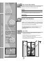
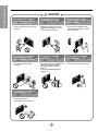
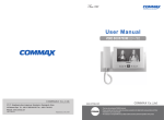
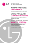
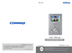
website http://www.lgservice.com
e-mail http://www.lgeservice.com/techsup.html
ROOM AIR CONDITIONER
OWNER'S MANUAL
Please read the operating instructions and safety precautions carefully
and thoroughly before installing and operating your room air conditioner.
MANUEL D'UTILISATION
CLIMATISEUR DE FENÊTRE
Veuillez lire attentivement et en entier ce guide d’utilisation et les
mesures de sécurité ci-incluses avant de procéder à l’installation et au
fonctionnement de votre climatiseur.
AIRE ACONDICIONADOR
MANUAL DEL PROPIETARIO
Por favor lea las instrucciones de operación y las precauciones de
seguridad cuidadosa y totalmente antes de instalar y operar su
acondicionador de aire de ventana.
MODELS, MODÈLES, MODELOS:
LXA0810ACL
LXA1010ACL
LXA1030ACL
LXA1210ACL
LXA1230ACL
Safety Precautions
Safety Precautions
Safety Precautions .............3
FOR YOUR RECORDS
Staple your receipt to this page in case you need it later.
Write down the model and serial numbers here:
Model #
Serial #
You can find them on a label on the side of each unit.
Electrical Data
Electrical Data ....................5
About the Controls on
the Air Conditioner
Electrical Data
About the Controls on
the Air Conditioner
Dealer's Name
Date Purchased
READ THIS MANUAL
Controls..............................6
Ventilation ..........................8
Air Direction........................8
Care and Maintenance
Features and Installation
Features
and Installation
Before you call for service...
Air Filter Cleaning...............9
How to Attach Front Grille to
Cabinet...............................9
Before you call
for service...
Inside you will find many helpful hints on how to use and
maintain your air conditioner properly. Just a little preventive
care on your part can save you a great deal of time and
money over the life of your air conditioner.
You'll find many answers to common problems in the chart
of troubleshooting tips. If you review our chart of
Troubleshooting Tips first, you may not need to call for
service at all.
CAUTION
• Contact an authorized Service technician for repair or
maintenance of this unit.
• The air conditioner is not intended for use by young
children or invalids without supervision.
• Young children should be supervised to ensure that they
do not play with the air conditioner.
Features ...........................10
How to Install the Unit ......11
How to Replace the Unit ..11
Installation Kits Contents..12
Normal Operation ..............15
Abnormal Operation ..........15
2
To prevent injury to the user or other people and property damage, the following instructions must be
followed.
■ Incorrect operation due to ignoring of instruction will cause harm or damage.
The seriousness is classified by the following indications.
WARNING
: This symbol indicates the possibility of death or serious injury.
CAUTION
symbol indicates the possibility of injury or damage to
: This
properties only.
■ Meanings of symbols used in this manual are as shown below.
Be sure not to do this.
Be sure to follow the instruction.
WARNING
WARNING
Plug in the power plug
properly.
Do not operate or stop the
unit by inserting or pulling
out the power plug.
Do not damage or use an
unspecified power cord.
• Otherwise, it will cause electric
shock or fire due to heat
generation.
• It will cause electric shock or fire
due to heat generation.
• It will cause electric shock or fire.
• If the power cord is damaged, it
must be replaced by the
manufacturer or an authorized
service center or a similarly qualified
person in order to avoid a hazard.
Do not modify power cord
length or share the outlet
with other appliances.
Do not operate with wet
hand or in damp
environment.
Do not direct airflow at room
occupants only.
• It will cause electric shock or fire
due to heat generation.
• It will cause electric shock.
• This could damage your health.
3
Safety Precautions
Safety Precautions
Safety Precautions
CAUTION
CAUTION
When the air filter is to be
removed, do not touch the
metal parts of the unit.
Do not clean the air
conditioner with water.
When the unit is to be
cleaned, switch off, and turn
off the breaker.
• They are sharp and may cause
an injury.
• Water may enter the unit and
degrade the insulation. It may
cause an electric shock.
• Since the fan rotates at high
speed during operation, it may
cause an injury.
Do not put a pet or house
plant where it will be
exposed to direct air flow.
Do not use for special
purposes.
Do not operate switches
with wet hands.
• This could injure the pets
or plants.
• Do not use this air conditioner to
preserve precision devices,
food, pets, plants, and art
objects.
It may cause deterioration of
quality, etc.
• It may cause an electric shock.
Do not apply an insecticide
or flammable spray.
• It may cause a fire or
deformation of the cabinet.
4
Electrical Data
Electrical Data(For 115V model)
Line Cord Plug
Use Wall Receptacle
Do not under any
circumstances cut
or remove the
grounding prong
from the plug.
Power Supply
Standard 125V, 3-wire grounding
receptacle rated 15A, 125V AC
Power supply cord with
3-prong grounding plug
USE OF EXTENSION CORDS
Because of potential safety hazards, we strongly discourage the use of an extension cord. However, if you wish to
use an extension cord, use a CSA certified/UL-listed 3-wire (grounding) extension cord, rated 15A, 125V.
Electrical Data(For 230/208V model)
Line Cord Plug
Use Wall Receptacle
Do not under any
circumstances cut
or remove the
grounding prong
from the plug.
Power supply cord with
3-prong grounding plug
Use 15 AMP
time delay fuse or
circuit breaker.
Tandem
type
Standard 250V, 3-wire grounding
receptacle rated 15A, 250V AC
Do not under any
circumstances cut
or remove the
grounding prong
from the plug.
Power supply cord with
3-prong grounding plug
Power Supply
Perpendicular
type
Standard 250V, 3-wire grounding
receptacle rated 20A, 250V AC
Use 20 AMP
time delay fuse or
circuit breaker.
Refer to the nameplate
for correct fusing.
All wiring should be made in accordance with local electrical codes and regulations.
NOTE : Aluminum house wiring may pose special problems. Consult a qualified electrician.
■ ELECTRICAL SAFETY
IMPORTANT GROUNDING INSTRUCTIONS
Air conditioner has a three-prong grounding plug
on its power supply cord, which must be plugged
into properly grounded three-prong wall
receptacle for your protection against possible
shock hazard.
FUSE – Use a time-delay fuse or circuit breaker.
Refer to the nameplate for proper power supply
requirements.
5
208, 230, and 208/230 VOLT UNITS
These units are equipped with a three-prong
grounding plug on the power supply cord, which
must be plugged into a matching properly
grounded three-prong wall receptacle for your
protection against possible shock hazard. If such
an outlet is not present, one must be installed by a
qualified electrician in accordance with the National
Electrical Code and local codes and ordinances.
NOTE: DO NOT USE AN EXTENSION CORD
ON 208, 230, AND 208/230 VOLT UNITS.
Electrical Data
Use 15 AMP time
delay fuse or 15 AMP
circuit breaker.
Parallel
type
About the Controls on the Air Conditioner
The controls will look like one of the following:
Controls – Cooling Only
Operation
Off
Med
Fan
High
Cool
Low
Fan
Med
Cool
Off
Med Fan
Low Fan
High Cool
Med Cool
Low Cool
- Turns air conditioner off.
- Med speed fan operation without cooling.
- Low speed fan operation without cooling.
- Cooling with high speed fan operation.
- Cooling with med speed fan operation.
- Cooling with low speed fan operation.
About the Controls on
the Air Conditioner
Low Cool
Thermostat
4
5
Coo
ler
6
3
7
2
8
1
This automatically controls the temperature of the indoor air.
Turn the knob so that arrow points to the larger marks for
greater cooling. Point the arrow to the smaller marks for more
moderate cooling.
(i.e. the higher number, the greater cooling)
9
• FOR NORMAL COOLING
• ENERGY SAVER (optional)
1. Turn the Operation Knob to the High Cool from
the Low Cool setting.
2. Set the Thermostat control to the desired
temperature mark 5 (the mid-point is a good
starting position). If the room temperature is not
satisfactory after a reasonable time, adjust the
control to a cooler or warmer setting, as
appropriate.
On : Both the fan and the compressor turn on and
turn off together while operation knob is set to
the Cool position.
You can get the more economical operation.
Off : The fan runs constantly while operation knob is
set to the Cool position.
Energy Saver
• FOR MAXIMUM COOLING
Off
1. Turn the Operation Knob to the High Cool setting.
2. Set the Thermostat control to the largest 9
temperature mark.
On
You can access the Energy Saver switch when you
open the inlet grille.
• FOR QUIETER OPERATION
1. Turn the Operation Knob to the Low Cool setting.
2. Set the Thermostat control as needed.
6
The controls will look like one of the following:
Controls – Cooling & Heating
Operation
O
Off
Fan
(
(
Low Cool
High Cool
Low Heat
High Heat
(
(
(
(
o ) :Turns the air conditioner off.
) : The low fan speed operation without cooling
(heating).
) : Cooling with the low speed fan operation.
) : Cooling with the high speed fan operation.
) : Heating with the low speed fan operation.
) : Heating with the high speed fan operation.
Turn the thermostat control to the desired setting. The central position is
a normal setting for average conditions. You can change this setting, if
necessary, in accordance with your temperature preference.
The thermostat automatically controls cooling or heating, but the fan
runs continuously whenever the air conditioner is in operation. If the
room is too warm, turn the thermostat control clockwise. If the room is
too cool, turn the thermostat control counterclockwise.
Warmer
Cooler
• THE AIR CONDITIONER
• HEAT PUMP MODELS
This automatically controls the temperature of the
indoor air.
The compressor will turn on and off to keep the room
at the setting temperature.
In the heating operation, the electric heater will turn on
and off to keep the room at the setting temperature.
When the outdoor temperature is lower than
-4°C (24°F), the electric heater will turn on instead of
the heat pump.
CAUTION
A slight heat odor may come from the unit
when first switching to HEAT after the
cooling season is over. This odor, caused
by fine dust particles on the heater, will
disappear quickly. This is harmless.
When the air conditioner has been performed its
cooling or heating operation and is turned off or
set to the fan position, wait at least 3 minutes
before resetting to the cooling operation again.
7
About the Controls on
the Air Conditioner
Thermostat
Additional controls and important information.
Ventilation
The ventilation lever is located in the right of the air discharge.
The ventilation lever must be in the CLOSE position in order to
maintain the best cooling conditions.
When fresh air is necessary in the room, set the ventilation lever to
the OPEN position.
The damper is opened and room air is exhausted outside.
PULL OPEN / PUSH CLOSE
About the Controls on
the Air Conditioner
Air Direction
The direction of air can be controlled wherever you want by
adjusting the horizontal louver and the vertical louver.
• HORIZONTAL AIR-DIRECTION CONTROL
The horizontal air direction is adjusted by moving vertical louver.
The lever of vertical louver is located in the right and left side of
the air discharge.
• VERTICAL AIR-DIRECTION CONTROL
The vertical air direction is adjusted by moving the horizontal
louver.
8
Care and Maintenance
TURN THE AIR CONDITIONER OFF AND REMOVE THE PLUG FROM THE POWER OUTLET.
Air Filter Cleaning
The air filter should be checked at least twice a month to see if cleaning is necessary.
Trapped particles in the filter will build up and block the airflow. This reduces the cooling
capacity and also causes an accumulation of frost on the cooling coils.
If the filter becomes turn or damaged you should replace
immediately. Replacement filters are available from your
salesperson, dealer, and the authorized customer service
centers.
1. Open the inlet grille downward by pulling out the top of the
inlet grille.
2. Remove the air filter from the front grille assembly by
pulling the air filter up slightly.
3. Wash the filter using lukewarm water below 40°C (104°F).
4. Gently shake the excess water from the filter completely.
Replace the filter.
The front grille can be removed for cleaning or to check the model and serial numbers.
For your safety, you should attach the front grille as the following procedures.
1. Pull down front grille from the cabinet
top.
2. Push front grille’s tips toward the cabinet
in order to insert front grille’s tabs into
the cabinet.
9
3. Open the inlet grille.
4. Tighten the screw through the front grille
into the plate of control box.
5. Close inlet grille.
About the Controls on
the Air Conditioner
How to Attach Front Grille to Cabinet
Features and Installation
Learning parts name prior to installation will help you understand the installation procedure.
Features
The Unit
1
5
7
3
6
2
4
11
8 9 10 13 14 12 15
The Sleeve and the Rear Grille (optional)
Features and Installation
17
18
16
1. CABINET
11. EVAPORATOR
2. HORIZONTAL AIR DEFLECTOR
(Vertical Louver)
12. CONDENSER
3. VERTICAL AIR DEFLECTOR
(Horizontal Louver)
14. BASE PAN
13. COMPRESSOR
15. BRACE
4. AIR DISCHARGE
16. SLEEVE ASSEMBLY
(Including Expanded Aluminum Rear grille,
optional)
5. FRONT GRILLE
6. INLET GRILLE (Air Intake)
7. AIR FILTER
17. REAR GRILLE
(Expanded Aluminum Rear grille, optional)
8. CONTROL BOARD
18. REAR GRILLE
(Aluminum louvered Rear grille, optional)
9. KNOBS
10. POWER CORD
10
How to Install the Unit
CAUTION : There are sharp edges that can cause serious cuts.
CAUTION : When lifting the air conditioner, it is HEAVY. Use 2 peoples to lift.
For existing sleeve, you should measure the wall sleeve dimensions.
You can install the new air conditioner according to these installation instructions to achieve the best
performence. All wall sleeves used to mount the new air conditioner must be in good structural
condition and have the rear grille that securely attaches to the sleeve or the flange of the sleeve to
secure the new air conditioner.
With the LG sleeve, you can maintain the best performance of the new air conditioner.
If you keep the existing sleeve, you run the risk of poor performance or product failure.
This is not covered under the LG warranty.
Dimension of air conditioner
Dimension of sleeve assembly (optional)
26"
(662 mm)
24-21/32"
(626 mm)
15- 17/32"
(394 mm)
14-13/32"
(366 mm)
19-21/32"
(499 mm)
How to Replace the Unit
Note : When you completed the installation, the new air conditioner unit
should have a rearward slope, as shown below.
1. Remove the old air conditioner from the wall sleeve and
prepare the wall sleeve.
Clean the interior of the sleeve (do not disturb the insulation
or seals).
1/4 Bubble
The wall sleeve must be fastened in the wall securely before
of the level
installing the new air conditioner.
11
Features and Installation
16-23/32"
(425 mm)
18"(458 mm)
Installation Kits Contents
1 Insulation Front (1 ea)
2 Insulation Horizontal (2 ea)
(Adhesive backed)
2,100 mm
670 mm
Sleeve Assembly
(optional, including expanded
aluminum metal grille)
3 Insulation Vertical (4 ea) 4 Support Block (4 ea) 5 Baffle (2 ea)
(Adhesive backed)
(Adhesive backed)
(Plastic sheet)
Louvered Grille
(optional)
2
355 mm
Air Conditioner
Features and Installation
1
3
4
Trim (2 ea)
5
12
2. Prepare the wall sleeve for
installation of the new unit according
to the following installation
procedures. Before you prepare the
wall sleeve, you should check the
wall sleeve dimensions.
3. Redirect the louvers at the back of
the wall sleeves as following A and B
lengths in the below table.
Width of the existing
wall sleeve
A
B
25-1/2" (648 mm)
2-3/4" (70 mm)
4-3/4" (120 mm)
25-3/4" (654 mm)
2-3/4" (70 mm)
5"
(130 mm)
26"
3"
5"
(130 mm)
(660 mm)
(75 mm)
26-3/4" (680 mm)
3-1/4" (80 mm)
5-1/2" (140 mm)
27"
3-1/2" (90 mm)
5-1/2" (140 mm)
(686 mm)
1
/2"
A (12 mm)
45~60°
1-1/4"
(32 mm) B
45~60°
Wall
4. Sleeve (up to 18 inches deep)
When the depth of your existing sleeve
is deeper than 18", please skip to step 5.
Remove the backing from horizontal
insulation and attach them to the inside
of the wall sleeve as shown below.
45~60°
Top view of the wall sleeve
Wall
Insulation
Horizontal
(2 ea)
Wall
Wall Sleeve
Front
Remove the backing from insulation
vertical and attach them to the inside
of the wall sleeve, as shown below.
B
Wall
Wall Sleeve
Front
5. Sleeve (18~22 inches deep)
When the depth of your existing
sleeve is not deeper than 18", please
skip to step 6.
Cut the baffles and the support blocks
as following C length in the below
table.
C
Depth of the existing
wall sleeve
13
C
18-5/8" (473 mm)
3 4
19-3/4" (502 mm)
1-3/4" (45 mm)
22"
4"
(559 mm)
/"
Support
Block
(20 mm)
(100 mm)
Baffle
C
Features and Installation
A
A+1/4"
(6 mm)
Remove the backing from vertical and
horizontal insulation and attach them to
the inside of the wall sleeve as shown
below.
Wall
Remove the backing from the support
blocks and attach them to the inside of
Wall
the wall sleeve as shown below. Slide Sleeve
the baffles in the slots of the support
blocks.
B+1/4"
(6 mm)
Insulation
Horizontal
Insulation
Vertical
Front
A
Remove the backing from vertical
insulation and attach them to the back
of the unit as shown below.
B
Vertical
Insulation
Features and Installation
6. Install the new unit into the wall sleeve.
Wall
7. Insert front insulation between the wall
sleeve and the unit. A flat-bladed
screwdriver or putty knife is
recommended.
Wall Sleeve
Front
Wall
8. To assemble trim, insert the snaps into
the slots of others.
To install trim to the sleeve, slide the
trim through the unit until it is flush
with the wall sleeve.
Trim (2 ea)
14
Before you call for service...
Troubleshooting Tips Save time and money!
Review the chart below first and you may not need to call for service.
Normal Operation
• You may hear a pinging noise caused by water being picked up and thrown against the condenser
on rainy days or when the humidity is high. This design feature helps remove moisture and improve
efficiency.
• You may hear the thermostat click when the compressor cycles on and off.
• Water will collect in the base pan during high humidity or on rainy days. The water may overflow
and drip from the outdoor side of the unit.
• The fan may run even when the compressor does not.
Abnormal Operation
Problem
Air conditioner
does not start
Air conditioner
does not cool as it
should
What To Do
■ The air conditioner is
unplugged.
• Make sure the air conditioner plug is pushed
completely into the outlet.
■ The fuse is blown/circuit
breaker is tripped.
• Check the house fuse/circuit breaker box and
replace the fuse or reset the breaker.
■ Power failure.
• If power failure occurs, turn the mode control to OFF.
When power is restored, wait 3 minutes to restart the
air conditioner to prevent tripping of the compressor
overload.
■ Airflow is restricted.
• Make sure there are no curtains, blinds, or furniture
blocking the front of the air conditioner.
■ The THERMOSTAT may
not be set high enough.
• Turn the knob to a higher number. The highest
setting provides maximum cooling.
■ The air filter is dirty.
• Clean the filter at least every 2 weeks.
See the operating instructions section.
■ The room may have been
hot.
• When the air conditioner is first turned on,
you need to allow time for the room to cool down.
■ Cold air is escaping.
• Check for open furnace floor registers
and cold air returns.
• Set the air conditioner's vent to the closed position.
■ Cooling coils have iced up.
• See Air Conditioner Freezing Up below.
■ Ice blocks the air flow and
stops the air conditioner
from cooling the room.
• Set the mode control at Med Fan or High Cool with
the thermostat at 1 or 2.
15
youfor
callservice...
for service...
Before Before
you call
Air conditioner
freezing up
Possible Causes