1
Symantec™ Advanced Manager for
Security Gateways (Group 1),
Symantec™ Event Manager for
Security Gateways (Group 1)
Administrator’s Guide
Supported version: 2.0.1
Symantec Advanced Manager for Security Gateways,
Symantec Event Manager for Security Gateways
Administrator’s Guide
The software described in this book is furnished under a license agreement and
may be used only in accordance with the terms of the agreement.
March 10, 2004
Copyright notice
Copyright 1998–2004 Symantec Corporation.
All Rights Reserved.
Any technical documentation that is made available by Symantec Corporation is
the copyrighted work of Symantec Corporation and is owned by Symantec
Corporation.
NO WARRANTY. The technical documentation is being delivered to you AS-IS
and Symantec Corporation makes no warranty as to its accuracy or use. Any use
of the technical documentation or the information contained therein is at the
risk of the user. Documentation may include technical or other inaccuracies or
typographical errors. Symantec reserves the right to make changes without
prior notice.
No part of this publication may be copied without the express written
permission of Symantec Corporation, 20330 Stevens Creek Blvd., Cupertino, CA
95014.
Trademarks
Symantec, the Symantec logo, and Norton AntiVirus are U.S. registered
trademarks of Symantec Corporation. LiveUpdate, LiveUpdate Administration
Utility, Symantec AntiVirus, and Symantec Security Response are trademarks of
Symantec Corporation.
Other brands and product names mentioned in this manual may be trademarks
or registered trademarks of their respective companies and are hereby
acknowledged.
Printed in the United States of America.
10 9 8 7 6 5 4 3 2 1
Technical support
As part of Symantec Security Response, the Symantec global Technical Support
group maintains support centers throughout the world. The Technical Support
group’s primary role is to respond to specific questions on product feature/
function, installation, and configuration, as well as to author content for our
Web-accessible Knowledge Base. The Technical Support group works
collaboratively with the other functional areas within Symantec to answer your
questions in a timely fashion. For example, the Technical Support group works
with Product Engineering as well as Symantec Security Response to provide
Alerting Services and Virus Definition Updates for virus outbreaks and security
alerts.
Symantec technical support offerings include:
■
A range of support options that give you the flexibility to select the right
amount of service for any size organization
■
Telephone and Web support components that provide rapid response and
up-to-the-minute information
■
Upgrade insurance that delivers automatic software upgrade protection
■
Content Updates for virus definitions and security signatures that ensure
the highest level of protection
■
Global support from Symantec Security Response experts, which is
available 24 hours a day, 7 days a week worldwide in a variety of languages
for those customers enrolled in the Platinum Support program
Advanced features, such as the Symantec Alerting Service and Technical
Account Manager role, offer enhanced response and proactive security
support
Please visit our Web site for current information on Support Programs. The
specific features available may vary based on the level of support purchased and
the specific product that you are using.
■
Licensing and registration
If the product that you are implementing requires registration and/or a license
key, the fastest and easiest way to register your service is to access the
Symantec licensing and registration site at https://licensing.symantec.com.
See “Licensing” on page 419.
Contacting Technical Support
Customers with a current maintenance agreement may contact the Technical
Support group by phone or online at www.symantec.com/techsupp/.
Customers with Platinum support agreements may contact Platinum Technical
Support by the Platinum Web site at www-secure.symantec.com/platinum/.
When contacting the Technical Support group, please have the following:
■
Product release level
■
Hardware information
■
Available memory, disk space, NIC information
■
Operating system
■
Version and patch level
■
Network topology
■
Router, gateway, and IP address information
■
Problem description
■
Error messages/log files
■
Troubleshooting performed prior to contacting Symantec
■
Recent software configuration changes and/or network changes
Customer Service
To contact Enterprise Customer Service online, go to www.symantec.com/
techsupp/, select the appropriate Global Site for your country, then select the
enterprise Continue link. Customer Service is available to assist with the
following types of issues:
■
Questions regarding product licensing or serialization
■
Product registration updates such as address or name changes
■
General product information (features, language availability, local dealers)
■
Latest information on product updates and upgrades
■
Information on upgrade insurance and maintenance contracts
■
Information on Symantec Value License Program
■
Advice on Symantec’s technical support options
■
Nontechnical presales questions
■
Missing or defective CD-ROMs or manuals
Contents
Section 1
Managing security gateways through SESA
Chapter 1
Introducing security gateway management through
SESA
Managing security gateways through SESA .................................................... 16
Security gateway products that integrate with SESA .................................... 17
Symantec Advanced Manager for Security Gateways (Group 1)
v2.0.1 ...................................................................................................... 18
Symantec Event Manager for Security Gateways (Group 1)
v2.0.1 ...................................................................................................... 19
About this guide ................................................................................................... 21
Where to find more information ....................................................................... 21
Chapter 2
How security gateways are managed through SESA
Managing security gateways through SESA .................................................... 23
About Symantec Enterprise Security Architecture ........................................ 24
SESA Components ....................................................................................... 24
SESA administrative features used with security gateways ......................... 26
Organizational units ................................................................................... 26
SESA users .................................................................................................... 28
Roles in SESA ............................................................................................... 29
Advanced management concepts ...................................................................... 30
Advanced Manager configuration components ...................................... 30
Configuration revisions .............................................................................. 31
Associating a policy or location setting ................................................... 32
Validating a configuration ......................................................................... 32
Activating a configuration ......................................................................... 32
Scalable management with organizational units ........................................... 33
Organizational units ................................................................................... 33
Event management concepts ............................................................................. 35
Event logging and viewing ......................................................................... 35
Alert and alert notifications ....................................................................... 35
Centralized reporting .................................................................................. 35
6 Contents
Chapter 3
Getting started with Symantec Advanced Manager
Pre-installation tasks .......................................................................................... 37
Accessing the SESA Console .............................................................................. 38
Default SESA logon privileges ................................................................... 38
Log on prerequisites .................................................................................... 39
Logging on to the SESA Console ................................................................ 39
Changing your password ............................................................................ 40
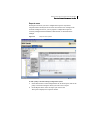
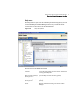
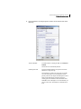
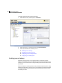
Symantec Advanced Manager user interface .................................................. 42
Viewing security gateway configurations in the SESA Console ........... 44
Understanding menus ................................................................................ 46
Toolbar buttons ............................................................................................ 54
Editing security gateway configurations in the SESA Console ............ 55
Chapter 4
Administering security gateways through SESA
About administering security gateways through SESA ................................ 57
Symantec Advanced Manager administrative commands ............................ 57
Creating a new policy setting ..................................................................... 58
Creating a new location setting ................................................................. 59
Copying policy or location settings ........................................................... 60
Discarding pending changes ...................................................................... 60
Deleting policy or location settings .......................................................... 61
Viewing a validation report ........................................................................ 62
Validating policy or location settings ....................................................... 62
Activating policy or location settings ....................................................... 63
Viewing security gateways ......................................................................... 64
Refreshing the display ................................................................................ 67
Creating local administrator access accounts ................................................. 67
Configuring machine accounts .......................................................................... 69
Configuring process restart ............................................................................... 72
Network security best practices ........................................................................ 74
Section 2
Configuring security gateways
Chapter 5
Understanding security gateway concepts
About security gateway concepts ...................................................................... 79
Configuring network entities ............................................................................. 80
Configuring host network entities ............................................................ 81
Configuring subnet network entities ........................................................ 82
Configuring domain name network entities ............................................ 84
Configuring security gateway network entities ...................................... 85
Contents
Configuring group network entities ......................................................... 88
Configuring VPN security entities ............................................................ 90
Configuring users ................................................................................................ 93
Configuring user groups ...................................................................................100
Configuring service groups ..............................................................................104
Configuring CIFS service group parameters .........................................106
Configuring FTP service group parameters ..........................................109
Configuring HTTP service group parameters .......................................110
Configuring NNTP service group parameters .......................................113
Configuring RealAudio service group parameters ...............................115
Configuring SMTP service group parameters .......................................116
Chapter 6
Configuring DNS
DNS records ........................................................................................................121
DNS proxy ...........................................................................................................122
DNS authority ....................................................................................................124
DNS forwarders ..................................................................................................126
DNS hosts ............................................................................................................127
DNS mail servers ...............................................................................................128
DNS name servers ..............................................................................................130
DNS recursion ....................................................................................................131
DNS root servers ................................................................................................132
DNS subnets .......................................................................................................133
Dual-level DNS configuration ..........................................................................135
Chapter 7
Enabling firewall access
Configuring rules ...............................................................................................137
Preventing attacks using HTTP URL patterns ......................................145
Passing traceroute .....................................................................................145
Removing HTTP packet headers .............................................................146
Preventing the security gateway from being used as a proxy ............146
Using the Universe network entity .........................................................147
Defining antispam rules ...........................................................................147
Configuring proxies ...........................................................................................149
CIFS proxy ...................................................................................................150
DNS proxy ...................................................................................................152
FTP proxy ....................................................................................................156
GSP proxy ....................................................................................................159
H.323 proxy ................................................................................................162
Configuring H.323 aliases ........................................................................165
HTTP proxy .................................................................................................169
NBDGRAM proxy .......................................................................................169
7
8 Contents
NNTP proxy ................................................................................................ 171
NTP proxy ................................................................................................... 174
Ping proxy ................................................................................................... 176
RCMD proxy ................................................................................................ 177
RTSP proxy ................................................................................................. 178
SMTP proxy ................................................................................................ 180
Telnet proxy ............................................................................................... 185
Configuring network protocols ....................................................................... 187
Configuring IP-based protocol properties ............................................. 188
Configuring TCP/UDP-based protocols .................................................. 189
Configuring ICMP-based protocols ......................................................... 191
Chapter 8
Controlling service access
Configuring filters ............................................................................................. 193
Creating an allow filter ............................................................................. 194
Creating a filter group ............................................................................... 196
Defining time periods ....................................................................................... 198
Configuring a time period group ............................................................. 201
Specifying content filtering ............................................................................. 202
Ratings profiles .......................................................................................... 202
Rating modifications ................................................................................. 206
URL lists ...................................................................................................... 208
MIME types ................................................................................................. 209
File extensions ............................................................................................ 211
Newsgroups ................................................................................................ 213
Newsgroup profiles ................................................................................... 215
Configuring LiveUpdate ................................................................................... 217
Chapter 9
Controlling user access
Configuring authentication methods ............................................................. 220
Supported authentication types ...................................................................... 220
Authentication for dynamic users .................................................................. 221
PassGo Defender™ authentication .................................................................. 222
Entrust authentication ..................................................................................... 224
GWPassword authentication ........................................................................... 225
LDAP authentication ......................................................................................... 226
Configuring LDAP authentication service ............................................. 227
NT Domain authentication .............................................................................. 232
RADIUS authentication .................................................................................... 235
RSA SecurID® authentication .......................................................................... 236
Bellcore S/KEY™ authentication ..................................................................... 240
TACACs authentication .................................................................................... 241
Contents
Configuring the OOBA Daemon .......................................................................243
Configuring an authentication sequence .......................................................249
Chapter 10
Configuring secure VPN connections
About VPN tunnels ............................................................................................251
VPN policies ........................................................................................................252
Configuring a VPN policy for IPsec with IKE ........................................252
Configuring a VPN policy for IPsec with static key ..............................260
Global IKE policies .............................................................................................263
VPN tunnels ........................................................................................................267
Creating tunnels manually .......................................................................267
Chapter 11
Preventing attacks
About preventing attacks .................................................................................277
Understanding basic firewall protection settings ........................................278
Defining filters ...........................................................................................278
Enabling protection for logical network interfaces .............................284
Configuring address transforms .............................................................289
Redirecting services ..................................................................................295
NAT pool addressing .................................................................................301
Creating virtual clients .............................................................................307
Configuring antivirus component server settings .......................................311
Antivirus component server settings .....................................................311
Configuring antivirus mail options ................................................................314
Filtering mail based on file size ...............................................................315
Filtering mail based on address ...............................................................316
Filtering mail based on subject line ........................................................318
Filtering mail based on attachment names ...........................................319
Filtering mail based on attachment sizes ..............................................321
Customizing the virus detection message .............................................323
Configuring intrusion detection and intrusion prevention (IDS/IPS) .......325
Configuring portmap settings .................................................................325
Configuring event gating for specific event types ................................329
Enabling global event gating ....................................................................332
9
10 Contents
Section 3
Monitoring security gateway performance
Chapter 12
Managing SESA logging
About managing SESA logging ........................................................................ 337
Understanding how security gateways log events to SESA ........................ 338
Security gateway monitoring and logging features ..................................... 338
Optimizing SESA event logging ...................................................................... 339
Customizing the SESA Agent’s configuration ....................................... 340
Customizing the SESA Manager’s configuration ................................. 341
Customizing event reporting ........................................................................... 343
Customizing event reporting for security gateways that use
Symantec Event Manager (Group 1) v2.0.1 ................................... 343
Customizing event reporting for Symantec Event Manager for
Firewall ................................................................................................ 344
Managing log files ............................................................................................. 344
Managing log files for security gateways that use Symantec E
vent Manager (Group 1) v2.0.1 ........................................................ 345
Managing log files for Symantec Event Manager for Firewall
(legacy products) ................................................................................ 346
Configuring the logging service .............................................................. 346
Viewing and consolidating events .................................................................. 349
Managing events and alerts in SESA .............................................................. 350
Chapter 13
Viewing event reports
About viewing event reports ............................................................................ 351
Viewing reports .................................................................................................. 352
Firewall Event Family ............................................................................... 354
Security Gateways (Group 1) ................................................................... 355
Antivirus Event Family ............................................................................. 357
Network Intrusion Event Family ............................................................. 358
Intrusion Event Family ............................................................................. 359
System Event Family ................................................................................. 359
Sensitive Content Filtering and Content Filtering Event
Family .................................................................................................. 359
Sample reports ................................................................................................... 360
All Symantec Security Gateway network events .................................. 361
Possible attack events ............................................................................... 362
Possible attacks: By type ........................................................................... 363
Possible attacks: By source hostname .................................................... 364
Network Report .......................................................................................... 365
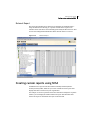
Creating custom reports using SESA .............................................................. 365
Contents
Chapter 14
Creating alerts and notifications
About creating alerts and notifications .........................................................367
Creating SESA alert configurations ................................................................368
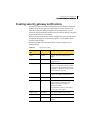
Creating security gateway notifications ........................................................369
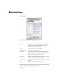
Audio notifications ....................................................................................370
Configuring Blacklist notifications .........................................................372
Client program notifications ....................................................................375
Email notifications ....................................................................................377
Pager notifications ....................................................................................378
SNMP notifications ....................................................................................381
Section 4
Appendices
Appendix A
Advanced system settings
Advanced policy system parameters ..............................................................389
Enabling reverse lookups .........................................................................390
Including host names in log files ............................................................391
Configuring reverse lookup timeout .......................................................391
Configuring a forwarding filter ...............................................................392
Advanced location system parameters ..........................................................393
Chapter 15
Joining security gateways to SESA
About joining SESA ...........................................................................................395
Preparing to join SESA ......................................................................................396
Configuring the local security gateway ..................................................397
Joining multiple security gateways to SESA for centralized
management .......................................................................................397
Joining SESA .......................................................................................................398
Determining your options for joining SESA ..........................................399
Exporting the local security gateway configuration to SESA .............400
Importing an existing policy and location settings from SESA .........404
Joining a cluster to SESA ..........................................................................407
Joining SESA for event management only .............................................412
Logging on to the SESA Console ......................................................................413
Troubleshooting problems when joining SESA ............................................413
Returning to local management ......................................................................414
Appendix B
Troubleshooting
Online troubleshooting help ............................................................................417
11
12 Contents
Appendix C
Licensing
Software licensing ............................................................................................. 419
Appendix D
Events
About events ....................................................................................................... 423
How events are processed ................................................................................ 424
Event Listing ....................................................................................................... 424
Appendix E
Customizing Symantec Event Manager for Firewall
(legacy products)
About customizing Symantec Event Manager for Firewall ........................ 431
Symantec Event Manager for Firewall configuration files ......................... 432
Modifying FirewallInformation.ini (required) ...................................... 433
Modifying DE_FirstPass.rule (optional) ................................................. 435
Modifying SEFLogSensor.ini (optional) ................................................. 445
Modifying RaptorExpert.ini (optional) ................................................... 448
Manually operating Symantec Event Manager for Firewall ....................... 450
Edit sensor log files ................................................................................... 450
Run batch files ........................................................................................... 451
Index
Section
Managing security
gateways through SESA
This section includes the following topics:
■
Introducing security gateway management through SESA
■
How security gateways are managed through SESA
■
Getting started with Symantec Advanced Manager
■
Administering security gateways through SESA
1
14
Chapter
Introducing security
gateway management
through SESA
This chapter includes the following topics:
■
Managing security gateways through SESA
■
Security gateway products that integrate with SESA
■
About this guide
■
Where to find more information
1
16 Introducing security gateway management through SESA
Managing security gateways through SESA
Managing security gateways through SESA
Symantec Advanced Manager for Security Gateways (Group 1) v2.0.1 and
Symantec Event Manager for Security Gateways (Group 1) v2.0.1 are integrated
with the Symantec Enterprise Security Architecture (SESA) to provide a
common framework to manage multiple Symantec enterprise security and
third-party products from a single, centralized location.
The SESA framework consists of a set of scalable, extensible, and secure
technologies that make integrated security products interoperable and
manageable, regardless of the size and complexity of your network.
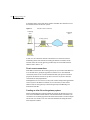
When managing security gateways locally, you configure and manage each
security gateway from its local management console. The local console is
accessed by pointing a supported Web browser to the security gateway’s
network-connected interface. For example, a host external to the security
gateway would direct its management connection to the security gateway’s
external interface, whereas a host on the protected network would point the
Web browser to the nearest inside interface of the security gateway.
In contrast, when managing security gateways through SESA, you can manage
multiple security gateways from a single user interface, regardless of the
network on which your SESA Manager resides. You can group them to reflect
your organizational structure and create common configurations that are
shared by security gateways that have the same security postures.
The event management capabilities of Symantec Event Manager for Security
Gateways, installed with Symantec Advanced Manager, give you up-to-date
information you need to make informed decisions about the security of your
network and related devices.
Introducing security gateway management through SESA
Security gateway products that integrate with SESA
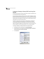
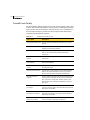
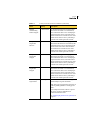
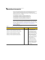
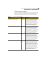
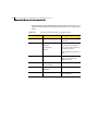
Security gateway products that integrate with SESA
Symantec offers two SESA-enabled products, described below, that let you
manage your security gateways through SESA. Each provides a different level of
SESA management for Symantec security gateways.
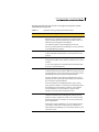
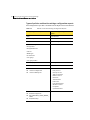
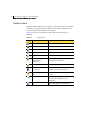
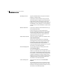
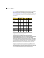
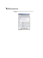
Table 1-1
How Symantec security gateways integrate with SESA
SESA integration Products
Supported security gateways
Symantec Advanced Manager for
Security Gateways (Group 1) v2.0.1
For policy configuration:
■
Symantec Gateway Security 5400 Series
v2.0
■
Symantec Enterprise Firewall v8.0
For event management:
Symantec Event Manager for Security
Gateways (Group 1) v2.0.1
■
Symantec Gateway Security 5400 Series
v2.0
■
Symantec Enterprise Firewall v8.0
■
Symantec Gateway Security 5110, 5200,
5300, 5310 v1.0*
■
Symantec VelociRaptor 500, 700, 1000,
1100, 1200, 1300, 1310 v1.5*
■
Symantec Enterprise Firewall v7.0*
■
Select third-party products (using a
separately purchased event collector)
For event management only:
■
Symantec Gateway Security 5400 Series
v2.0
■
Symantec Enterprise Firewall v8.0
■
Symantec Gateway Security 5110, 5200,
5300, 5310 v1.0*
■
Symantec VelociRaptor 500, 700, 1000,
1100, 1200, 1300, 1310 v1.5*
■
Symantec Enterprise Firewall v7.0*
■
Select third-party products (using a
separately purchased event collector)
* Security products marked with an asterisk do not have integrated SESA support. To
manage these products from SESA, you must install the Symantec Event Manager for
Firewall v1.0, which is included on your product CD-ROM. For installation instructions,
refer to the Symantec Advanced Manager for Security Gateways, Symantec Event
Manager for Security Gateways Integration Guide.
17
18 Introducing security gateway management through SESA
Security gateway products that integrate with SESA
Symantec Advanced Manager and Symantec Event Manager require the version
1.1.5 SESA Foundation Pack (purchased separately).
Your SESA environment must be installed and fully operational before
installing the Symantec Advanced Manager or Symantec Event Manager on the
SESA Manager workstation.
Consult the SymantecTM Enterprise Security Architecture Installation Guide and
the SymantecTM Enterprise Security Architecture Administrator’s Guide for
further information.
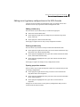
Symantec Advanced Manager for Security Gateways (Group 1) v2.0.1
Symantec Advanced Manager for Security Gateways is a software security
solution, installed on the SESA Manager computer, that plugs into the SESA
Console. It provides a Web-based graphical user interface through which you
can monitor and organize a large number of security gateways, along with other
SESA-compliant products.
Advanced management through SESA lets you manage both policies and
location settings of connected security gateways, in addition to collecting events
from those systems. SESA management also provides scalable management by
allowing multiple security gateways to share common policies and location
settings.
SESA management provides many features important to centralized and
scalable management, including:
■
Logical grouping of security gateways into organizational units
■
Management of multiple configurations
■
Sharing of configurations across security gateways
■
Validation of multiple configurations in a single action
■
Distribution of configurations to many security gateways in a single action
The Symantec Advanced Manager also includes the Symantec Event Manager
for Security Gateways (Group 1) v2.0.1 product (described in the next section)
for centralized event logging, alerting and reporting.
Introducing security gateway management through SESA
Security gateway products that integrate with SESA
Symantec Event Manager for Security Gateways (Group 1) v2.0.1
Symantec Event Manager for Security Gateways is a standards-based software
security solution that provides centralized logging, alerting, and reporting
across Symantec’s security gateway protection solutions and select third-party
products.
Symantec Event Manager delivers security information to the SESA DataStore,
letting you see a centralized, consistent view of your security events from the
SESA Console. Security events and log messages can be viewed in a variety of
predefined or custom report formats.
By collecting and formatting information from Symantec and third-party
supported products, the Symantec Event Manager consolidates and normalizes
security event data, making impending threats more easily identifiable.
Combining powerful alert notification, enterprise reporting and role-based
administration with a highly scalable secure architecture, the Symantec Event
Manager is ideally suited for medium-to-large enterprises and supported
security services environments.
If you have separately purchased an Event Collector for a third-party firewall
product, you can also view events generated by that product.
Symantec Event Manager for Security Gateways is installed on the SESA
Manager computer. You join each local security gateway to SESA using the
controls provided in the Security Gateway Management Interface (SGMI).
Symantec Event Manager is automatically installed if you install the Symantec
Advanced Manager for Security Gateways. You can also install the Symantec
Event Manager alone if you have systems that will be used only for event
management.
Symantec Event Manager for Firewall v1.0
To manage legacy products, the Symantec Event Manager for Firewall v1.0 is
also included on the Symantec Advanced Manager for Security Gateways and
Symantec Event Manager for Security Gateways CD-ROMs. Symantec Event
Manager integrates event collection for legacy Symantec security gateways (see
Table 1-1) and third-party security gateways with Symantec Enterprise Security
Architecture (SESA) version 1.1.5.
19
20 Introducing security gateway management through SESA
Security gateway products that integrate with SESA
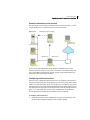
Event reporting to SESA
Some Symantec security gateways use a different process to report events to
SESA:
■
Products without integrated SESA support use an intermediate log server to
collect events. The log server houses a SESA Agent that formats the
messages, making them acceptable to SESA, and then forwards the events to
the SESA Manager.
■
Security gateways that host the agent locally do not require an intermediate
log server. When a security gateway joins SESA, the agent is downloaded to
the security gateway and activated. The SESA Agent formats the messages,
making them acceptable to SESA, and then forwards the events to the SESA
Manager.
See “Security gateway products that integrate with SESA” on page 17.
Customizing SESA event reporting
When first installed, Symantec Event Manager for Security Gateways (Group 1)
v2.0.1 (or Symantec Event Manager for Firewall v1.0) is configured to report a
subset of key (non-statistical) security events or log messages to SESA.
You can change the definition of events that are reported to SESA by editing the
configuration of the applicable Symantec Event Manager. You should carefully
consider your selections when determining the events to send to SESA; enabling
all events or statistical events incurs additional overhead, and may slow system
performance.
When managing Symantec security gateways that have integrated SESA
support, you can change the definition of events that are reported to SESA using
the event gating feature of the local security gateway.
When managing Symantec security gateways that do not have integrated SESA
support, you change the definition of events that are reported to SESA by
editing rule definitions in the DE_FirstPass.rule configuration file.
See See “Modifying DE_FirstPass.rule (optional)” on page 435.
A complete list of log messages is contained in the Symantec Security Gateways
Reference Guide.
Introducing security gateway management through SESA
About this guide
About this guide
This guide is intended for administrators who intend to join and manage
Symantec security gateways to the Symantec Enterprise Security Architecture
(SESA) using one of the following products:
■
Symantec Advanced Manager for Security Gateways (Group 1) v2.0.1
■
Symantec Event Manager for Security Gateways (Group 1) v2.0.1
The goal of this guide is to describe how to use the Symantec Advanced and
Event Manager products to manage security gateways in SESA. If appropriate,
related functions in the overall SESA Console are described along with
references to the SESA administrator documentation or online Help for more
information.
This guide assumes that your SESA environment is already installed and
working properly. If your SESA environment is not yet installed, consult the
Symantec Enterprise Security Architecture Installation Guide and the Symantec
Enterprise Security Architecture Administrator’s Guide.
Where to find more information
Additional information can be found in supporting documents that are provided
in PDF format on the product software CD-ROMs.
The following documents are provided on the CD-ROM:
■
Symantec™ Advanced Manager for Security Gateways (Group 1) v2.0.1,
Symantec™ Event Manager for Security Gateways (Group 1) v2.0.1
Administrator’s Guide (this guide)
■
Symantec™ Advanced Manager for Security Gateways (Group 1) v2.0.1,
Symantec™ Event Manager for Security Gateways (Group 1) v2.0.1
Integration Guide
■
Symantec™ Advanced Manager for Security Gateways (Group 1) v2.0.1,
Symantec™ Event Manager for Security Gateways (Group 1) v2.0.1 Release
Notes
21
22 Introducing security gateway management through SESA
Where to find more information
Chapter
2
How security gateways are
managed through SESA
This chapter includes the following topics:
■
Managing security gateways through SESA
■
About Symantec Enterprise Security Architecture
■
SESA administrative features used with security gateways
■
Advanced management concepts
■
Scalable management with organizational units
■
Event management concepts
Managing security gateways through SESA
Symantec security gateways and select third-party products are integrated and
managed through the Symantec Enterprise Security Architecture (SESA) using
the Symantec Advanced Manager for Security Gateways (Group 1) v2.0.1 and
the Symantec Event Manager for Security Gateways (Group 1) v2.0.1 security
products.
This chapter describes how security gateways are managed through SESA,
including:
■
The administrative features of SESA that are used to prepare and manage
security gateways in the SESA environment.
■
The concepts of advanced management and the tools you use to configure
and manage security gateways in the SESA environment.
■
The event management features of SESA that provide centralized logging,
alerting, and reporting for all managed security gateways.
24 How security gateways are managed through SESA
About Symantec Enterprise Security Architecture
The information presented in this chapter is conceptual in nature; step-by-step
procedures for administrative tasks are contained in Chapter 3 “Getting started
with Symantec Advanced Manager” on page 37.
If you are new to managing Symantec security gateways through SESA, you
should carefully review and familiarize yourself with the material in both
chapters before logging on and using the SESA Console.
About Symantec Enterprise Security Architecture
Symantec Enterprise Security Architecture (SESA) integrates multiple
Symantec enterprise security products and third-party products to provide
flexible control of security within organizations. SESA provides a common
management framework, known as the SESA foundation, for the SESA-enabled
security products that protect your IT infrastructure.
The SESA Console is the common user interface that provides manageable
integration of your security technologies (Symantec or otherwise).
For detailed information about SESA, see the Symantec Enterprise Security
Architecture Installation Guide and the Symantec Enterprise Security
Architecture Administrator’s Guide.
SESA Components
The SESA foundation consists of several individual components that together
provide a unique, scalable security infrastructure.
SESA uses SESA Agents that are installed on security product, a SESA Directory,
a SESA DataStore, and a SESA Manager. to collect, store, process, and report
security events to the SESA Console, and to distribute configuration changes to
SESA and SESA-enabled security products. In some cases, security products may
also use a SESA Event Collector to collect security events for forwarding to
SESA.
How security gateways are managed through SESA
About Symantec Enterprise Security Architecture
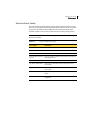
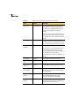
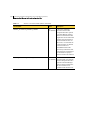
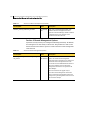
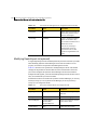
The following table describes how the security gateway integrates with the
individual SESA components.
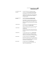
Table 2-1
Symantec security gateway relationship to SESA
SESA component
How the security gateway interacts
SESA Manager
The SESA Manager is the hub for the SESA Directory and the SESA
DataStore. It is a central processing unit (server) for the SESA
Agents, SESA DataStore, SESA Directory, and SESA Console. All
SESA data passes through the SESA Manager.
You install the Symantec Advanced Manager for Security
Gateways and the Symantec Event Manager for Security Gateways
on the SESA Manager computer.
SESA DataStore
This relational database stores all event and alert data generated
by SESA and SESA-enabled products, such as Symantec security
gateways.
SESA Directory
The SESA Directory stores the configuration data required to
manage SESA-enabled security products and SESA services on the
network.
As new security gateways are installed, SESA automatically adds
the devices to the SESA Directory.
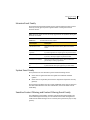
SESA Agent
The SESA Agent runs on the security gateway and handles
communications between the SESA-enabled security gateway and
the SESA Manager. It passes data from the security gateway to the
SESA Manager and receives product configuration data.
For legacy Symantec security gateways and third-party security
gateways, the SESA Agent works with installed event collectors to
pass event data to the SESA Manager.
For more information on managing Symantec legacy or thirdparty products from SESA, see the chapter “Introducing Symantec
Event Manager for Firewall (legacy products)” in the Symantec
Advanced Manager for Security Gateways, Symantec Event
Manager for Security Gateways Integration Guide.
SESA Console
The SESA Console is a Java-based framework that creates a
common environment for the management of diverse security
products. It runs in a Web browser with a secure connection and
provides the graphical user interface to view events and to push
down configurations.
With Symantec Advanced Manager, you use the SESA Console to
view, manage, and distribute security gateway configurations.
With Symantec Event Manager, you use the SESA Console to view
and analyze events.
25
26 How security gateways are managed through SESA
SESA administrative features used with security gateways
SESA administrative features used with security
gateways
To manage your security gateways in SESA, you must plan for and configure
some of SESA’s administrative features. You perform these tasks from the SESA
Console System view tab, using SESA wizards.
Features that you will configure include:
■
Organizational units that reflect the organization of your security gateways
■
Users who will use SESA to manage or monitor security gateways
■
Roles that define what security gateway users can see and do in the SESA
Console
Note: The SESA System view tab also lets you create configuration groups to
distribute configurations that supersede those distributed by organizational
units.
While you can use this method to distribute configurations for other security
products, you cannot use configuration groups to distribute Symantec security
gateway configurations.
Organizational units
Organizational units let you define the top level organization of your security
gateways so that your SESA environment reflects how your organization is
handling or plans to handle its security management needs.
You can create organizational units based on any of the following:
■
Business functions, such as marketing, operations, and accounts payable
■
IT functions
■
Product groups, such as antivirus and firewall
■
Location; regions, cities, or building floors
Symantec Advanced Manager lets you organize security gateways into logical
groupings, and apply the same policies to similar security gateways. As you add
new security gateways, you can use the policies that you have already created to
quickly provide them with configurations.
When you manage multiple security gateways, you can use the SESA concept of
organizational units to group your security gateways in the SESA Console
System view. This lets you more clearly see how the entire network is
structured.
How security gateways are managed through SESA
SESA administrative features used with security gateways
Organizational units also provide a mechanism to let member security gateways
inherit an associated policy and location setting, thereby simplifying
management of many systems.
For example, when a security gateway that is a member of a cluster joins SESA,
it and all other members of the cluster are automatically placed in a single
organizational unit. All cluster members inherit their configurations from the
configuration that is associated with the organizational unit. This enforces the
requirement that all members of a cluster must share the same configuration.
You cannot associate a policy or location settings to an individual cluster
member. If you try to run the Associate Wizard on a clustered security gateway,
you will receive an error message.
For Symantec Advanced Management, the process by which you register your
security gateway machines with SESA is the Join SESA Wizard. If you have
already created organizational units, when you run the Join SESA Wizard, you
can specify the organizational unit to which your security gateway machine will
belong. If you have not created organizational units, your security gateway
machines are assigned to the Default organizational unit when they join SESA.
Later, you can create organizational units to represent your security
environment and move the security gateway into one of them. If you create
organizational units before you join security gateways to SESA, you can
eliminate the step of having to move the security gateways to their intended
destinations.
Note: Symantec Advanced Manager supports single level organizational units.
For other products and other uses of SESA, you can create nested organizational
units using a hierarchical structure to reflect your organization’s management
structure.
27
28 How security gateways are managed through SESA
SESA administrative features used with security gateways
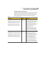
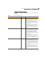
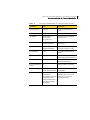
Default organizational units
The pre-configured organizational units in the following table already exist
when you access the SESA Console for the first time.
Table 2-2
Default organizational units
Organizational
Unit
Description
Default
The Default organizational unit contains computers on which SESA
Agents are installed, but have not yet been assigned to other
organizational units. When you create organizational units, you can
move computers from the Default unit to a newly created
organizational unit as necessary.
Managers
The Managers unit contains computers on which the SESA Manager is
installed. You cannot move computers that have SESA Managers
installed on them from the Managers unit to other organizational
units: SESA Managers always stay in the Managers organizational
unit.
When a SESA Manager computer also has a SESA-enabled security
product installed, the computer remains in the Managers unit only
and does not show in the Default unit or any other unit.
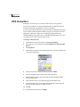
SESA users
SESA maintains a list of SESA users, who are people who have SESA
management or non-management roles.
A Default Administrator user is defined during SESA installation. The Default
Administrator has access rights to the entire SESA administrative domain.
When you first log on to the SESA Console, it will be as the Default
Administrator.
For ongoing use, you should determine how your SESA environment will be
accessed. Your choices include:
■
A single administrator
■
Multiple administrators, each managing a separate security product
■
Users whose purpose in accessing SESA is only event monitoring
■
Users who will be the recipients of notifications
If you do not plan to have a single administrator, you should create SESA users
for each type of SESA access you require.
When you create SESA users, they have no access rights. For users to log on to
the SESA Console, you must give them permissions appropriate to their
How security gateways are managed through SESA
SESA administrative features used with security gateways
management responsibilities. These permissions are defined in SESA roles that
you create and assign to users.
See “Roles in SESA” on page 29.
Roles in SESA
SESA uses role-based administration. A role is a set of permissions for specific
management operations. A SESA Console user can be a member of one or more
roles. The logon identity of SESA Console users determines their role
assignment during an administrative session.
Roles separate permissions for accessing and using SESA. Roles that you can
create for security gateway management in SESA include:
■
An event monitoring role
You can assign technicians who monitor events and alerts to a Security
Monitoring role. When they log on to SESA, this role lets them view data
from all types of SESA-enabled security products, but does not grant
permission to change product configurations.
■
A configuration management role
You can give your security gateway administrator a role assignment that
allows the user to change and distribute configurations but not to view
events from other security products.
■
The SESA Domain Administrator role
SESA installs with a SESA Domain Administrator role, which is assigned to
the Default Administrator user. The Domain Administrator role includes
permissions to add users, roles, organizational units, and configuration
groups to the SESA domain.
SESA users who do not belong to the SESA Domain Administrator role
cannot see the System view tab in the SESA Console. You can add users to
the Domain Administrator role to grant Domain Administrator Role
permissions and access to the System view tab.
29
30 How security gateways are managed through SESA
Advanced management concepts
Advanced management concepts
This section describes the concepts of advanced management and the tools you
use to configure and manage security gateways in the SESA environment.
To help you understand how Symantec Advanced Manager lets you manage
security gateways through SESA, you should become familiar with the following
advanced management concepts:
■
How the components of a security gateway configuration are created and
used in SESA.
See “Advanced Manager configuration components” on page 30.
■
How Symantec Advanced Manager handles configuration revisions.
See “Configuration revisions” on page 31.
■
How configurations are associated, validated, and activated for your security
gateways.
See “Associating a policy or location setting” on page 32, “Validating a
configuration” on page 32 and “Activating a configuration” on page 32.
■
How configurations are exported and inherited.
See “Advanced Manager configuration components” on page 30.
Advanced Manager configuration components
You manage SESA-enabled security gateways by creating and distributing
security gateway configurations that are stored in SESA.
A security gateway’s configuration is a combination of:
■
A policy and location settings
You configure policy and location settings in the SESA Console in the same
way as you configure them in the Security Gateway Management Interface
(SGMI).
The difference is, in SESA, you configure policy or location settings once
and then apply them to multiple security gateways.
■
System-specific settings that are specific to the local gateway
When the security gateway joins SESA, the system information about the
physical machine is sent to SESA.
When you join a security gateway to SESA, you can export and register a copy of
the security gateway’s local configuration with SESA, or you can inherit a
previously registered configuration. SESA stores the associated policy and
location settings for each registered system.
How security gateways are managed through SESA
Advanced management concepts
Understanding policies
A policy describes the security stance of the security gateway to which it is
applied. Using Symantec Advanced Manager, you can share policies among
multiple security gateways.
The policies you define using the SESA Console are identical to the policies you
define using the local management interface, Security Gateway Management
Interface (SGMI). They contain data such as firewall rules, service groups, VPN
policies, and content filtering.
For Symantec Gateway Security appliances, antivirus, intrusion detection, and
intrusion prevention policies can also be applied.
Understanding location settings
Location settings describe the network in which a security gateway lives by
grouping logical network and user definitions. They include definitions of
network entities, tunnels, and users.
Locations settings can be shared among multiple security gateways, but are
often uniquely defined for each specific location in which a single or clustered
Symantec security gateway environment exists.
As with policies, the location setting options that you configure using Symantec
Advanced Manager are identical to those that you configure in the Location
Settings window of the SGMI.
Understanding local system settings
Each security gateway that connects to SESA has some settings that apply only
to that system. System settings are configured locally through SGMI, and are
not configured using the SESA Console.
Local system settings include local system information, network interfaces and
routes, license features, and cluster configurations.
Before you distribute a configuration, Symantec Advanced Manager validates it
against the stored copy of your local system settings.
Configuration revisions
A revision is a version of a configuration. As you modify a configuration’s policy
or location settings, and deploy these modifications, a new revision is created.
Only two revisions are maintained by SESA at any given time: the revision that
has been distributed (currently active), and a working copy that may not yet
have been validated and activated.
31
32 How security gateways are managed through SESA
Advanced management concepts
When you make changes to a configuration, you can copy the current
configuration and work with the copy instead of working with the active
configuration.
Associating a policy or location setting
Every security gateway managed by Symantec Advanced Manager is configured
with a policy and location settings. For the security gateway to function
properly, the policy and location settings must function properly with each
other.
To ensure this, Symantec Advanced Manager validates the policy and location
settings against each other, and against the local system settings before they are
activated on a security gateway. Before the validation can take place, you must
associate the policy and location settings with a security gateway, so that
Symantec Advanced Manager knows which local system settings to use when
validating.
To determine which security gateways you will impact if you make a change to a
selected policy or location settings, you can use the Symantec Advanced
Manager Show all associated gateways feature to display all the security
gateways that are associated with the policy or location settings.
Validating a configuration
Validation is the process that checks a configuration for completeness, ensures
that all values are valid, and determines if all logical and physical references
between a policy, location settings, and a security gateway’s system settings can
be resolved. Symantec Advanced Manager uses validation to ensure that each
connected security gateway gets a policy and location settings that work for that
system.
Activating a configuration
Activation is the process that Symantec Advanced Manager for Security
Gateways uses to push a new version of a configuration down to all security
gateways that use it.
Successful validation is a required piece of the activation process. When you
select Activate from the Selection menu, SESA first validates the configuration,
and then, if validation is successful, activates the changes.
How security gateways are managed through SESA
Scalable management with organizational units
Scalable management with organizational units
Scalable management introduces the concept of organizational units and
physically separating security gateways in the SESA Console view. By separating
security gateways in this manner, you can more clearly see how the entire
network is structured. Organizational units also provide a mechanism to let
member security gateways inherit an associated policy and location settings,
simplifying management of many systems.
Organizational units
Organizational units are management objects that you can create using the
SESA Console. They are used to store information about computers in the SESA
Directory. Every security gateway that joins SESA is assigned to an
organizational unit.
Although you can use the Default organizational unit for all your computers,
creating your own organizational units can simplify the management of your
security gateways. Like a company organization chart, organizational units can
logically group the machines you manage.
You can create your organizational units to represent departments within your
organization, levels of access, geographical location, or any other logical
grouping. If you prefer, you can assign every security gateway to the same
organizational unit. However, you can gain greater benefit by planning and
logically grouping systems into their own organizational units.
Every security gateway has an associated policy and location settings. Similarly,
you can associate policy and location settings with an organizational unit, so
that they can be inherited by any security gateway that is in the organizational
unit. This mechanism lets you apply the same policy and location settings to
multiple security gateways.
For security gateways in a cluster, you must associate configurations with the
cluster’s organizational unit. This enforces the requirement that all members of
a cluster must share the same configuration. You cannot associate a policy or
location settings to an individual cluster member. If you try to run the Associate
Wizard on a clustered security gateway, you will receive an error message.
For instructions on creating an organizational unit, see the Symantec Enterprise
Security Architecture Administrator’s Guide or use the SESA Console Help
system.
33
34 How security gateways are managed through SESA
Scalable management with organizational units
Moving a security gateway into an organizational unit
When a security gateway first joins SESA, the Join SESA Wizard requires that
you select an organizational unit to which the security gateway will be assigned.
If you have not yet created organizational units, you must assign the security
gateway to the Default organizational unit. Later, you can create organizational
units to represent your security environment and move the security gateway
into one of them.
If you create organizational units before you join security gateways to SESA, you
can eliminate the step of having to move the security gateways to their intended
destinations.
For more information, see the section on moving a computer to a different
organizational unit in the Symantec Enterprise Security Architecture
Administrator’s Guide, or use the SESA Console Help.
Exporting and inheriting
When you place a security gateway in an organizational unit using the Join
SESA Wizard, you can also place its policy and location settings in the
organizational unit by choosing to export them. When you log on to the SESA
Console, the policies and location settings are available for you to modify. You
can change either the policy or location settings, and then validate and activate
your changes on the security gateway.
Alternately, if the organizational unit already has a policy and location settings
associated with it, you can choose to inherit them. When you do this, changes
that you make to the configuration do not have to be validated individually for
each security gateway. You can edit either the policy or location settings
associated with the organizational unit, and then validate and activate the
changes once.
Inheriting both the policy and location settings from an organizational unit
generally applies to either a clustered situation (because the cluster is
represented as an organizational unit), or to a network of security gateways that
are failovers for each other.
How security gateways are managed through SESA
Event management concepts
Event management concepts
SESA helps organizations manage security events by providing common logging
of normalized event data for SESA-supported and SESA-enabled security
products. In addition, SESA has a notification system for the events that are
generated by SESA-enabled security products and SESA itself. SESA also
provides robust reporting capabilities.
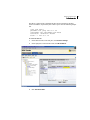
Event logging and viewing
SESA provides centralized logging and event viewing capabilities. Each
Symantec security gateway forwards events to its SESA Agent, which manages
and queues the events and sends them to a SESA Manager. The SESA Manager
then logs the events in the SESA DataStore.
Event viewing is provided through the SESA Console Event tab. You can query,
filter, and sort events to quickly find computers that are not protected, are outof-date, or have high-severity events occurring.
Alert and alert notifications
SESA lets you create alert configurations for events that are collected in the
SESA DataStore.
You can configure alerts to use a specific set of event criteria. You can also
specify that an alert will accumulate events until a certain number are received
or within a time interval. By specifying event criteria and applying thresholds,
you can use alerts to consolidate the many events that SESA-enabled security
products generate.
Alert configurations can also include notifications to pagers, SNMP traps, email,
and operating system event logs. You can define the notification recipients, day
and time ranges when specific recipients are notified, and custom data to
accompany the notification messages. Each notification recipient has one or
more preferred ways of receiving notification. You choose the user to notify for
a particular alert or group of alerts.
Centralized reporting
SESA provides centralized reporting capabilities, including graphical reports.
SESA installs with some common reports. Security gateways have additional
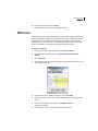
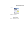
predefined reports. You can also create custom reports.
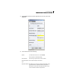
You can use reports to present statistics, recent activity, outbreak and intrusion
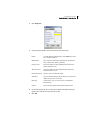
conditions, and so on. SESA provides a variety of report formats such as trend
graphs, pie charts, stacked bar charts, and tables, all of which let you drill down
35
36 How security gateways are managed through SESA
Event management concepts
to the particular data that you need. You can print current SESA Console views
of events and alerts as reports, or save the views as reports and export them to
other formats.
Chapter
3
Getting started with
Symantec Advanced
Manager
This chapter includes the following topics:
■
Pre-installation tasks
■
Accessing the SESA Console
■
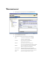
Symantec Advanced Manager user interface
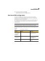
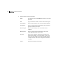
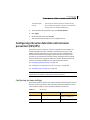
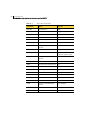
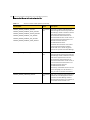
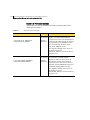
Pre-installation tasks
Before logging on and attempting to use Symantec Advanced Manager, ensure
you have completed the following tasks:
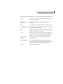
Table 3-1
Tasks required to access the SESA Console
Task
Procedure
To manage Symantec Gateway
Security 5400 Series appliances v2.0
or Symantec Enterprise Firewall v8.0,
install Symantec Advanced Manager
for Security Gateways (Group 1) v2.0.1
or Symantec Event Manager for
Security Gateways (Group 1) v2.0.1
See Section 2, Installing SESA Integration
Components for Symantec Advanced Manager
and Symantec Event Manager for Security
Gateways in the Integration Guide (located on
your product CD-ROM).
38 Getting started with Symantec Advanced Manager
Accessing the SESA Console
Table 3-1
Tasks required to access the SESA Console (Continued)
Task
Procedure
To manage Symantec legacy products
(such as Symantec Gateways Security
v1.0 appliances, Symantec Enterprise
Firewall v7.0, and VelociRaptor v1.5)
install Symantec Event Manager for
Firewall
See Section 3, Installing SESA Integration
Components for Symantec Event Manager for
Firewall in the Integration Guide (located on
your product CD-ROM).
Run the SESA Setup Wizard from the See Appendix B, Joining SESA in the Symantec
Security Gateway Management
Enterprise Firewall Administrator’s Guide
Interface (SGMI) of each local security (located on your product CD-ROM).
gateway that will join SESA.
Note: The Join SESA procedure is also repeated
for your convenience in Appendix E, Joining
SESA of this guide.
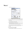
Access and log on to the SESA
Console.
“Accessing the SESA Console” on page 38.
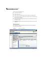
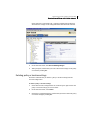
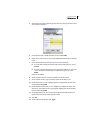
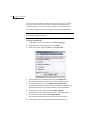
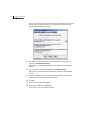
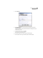
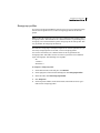
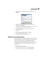
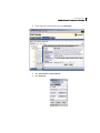
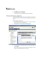
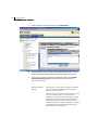
Accessing the SESA Console
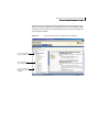
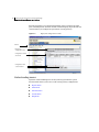
The SESA Console connects you to the SESA Manager. It displays in either a
Microsoft Internet Explorer or Netscape browser window.
Before you log on, ensure your system meets the minimum log on requirements,
as described in “Log on prerequisites” on page 39.
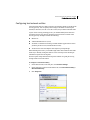
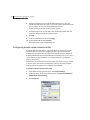
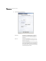
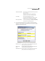
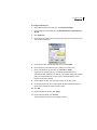
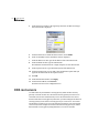
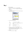
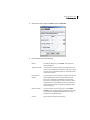
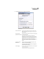
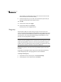
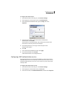
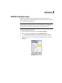
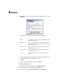
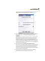
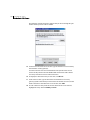
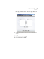
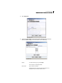
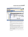
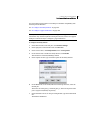
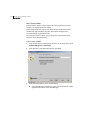
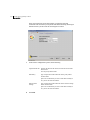
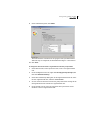
Then follow the logon procedure, described in “Logging on to the SESA Console”
on page 39.
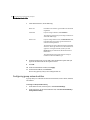
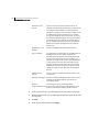
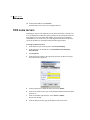
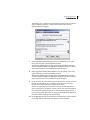
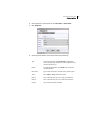
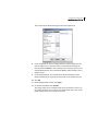
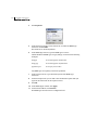
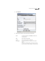
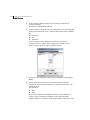
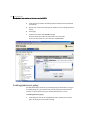
Default SESA logon privileges
All users who first log on to the SESA Console do so as a member of the Domain
Administrator role. The default role Domain Administrator is created when the
SESA Manager is installed. The Domain Administrator role provides complete
access to manage the entire Symantec Enterprise Security domain. The default
user, also created when the SESA Manager is installed, is automatically a
member of this role. To access the SESA Console the first time, you must log on
as this default user.
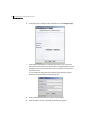
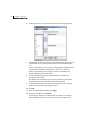
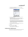
You can add other users to this role, but you cannot change any other
characteristics of the role. Any user who needs access to the System view tab to
create or modify management objects must be a member of the Domain
Getting started with Symantec Advanced Manager
Accessing the SESA Console
Administrator role. Once a user is a member of the Domain Administrator role,
no other roles are needed.
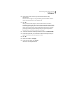
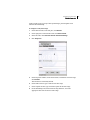
As soon as practical, you should develop and implement a plan for each user and
the level of access they require within the SESA infrastructure. Leaving all users
who access the system as members of the Domain Administrator role could
compromise the integrity of your secured environment.
A complete description of SESA roles and users is described in the chapter
“Defining the administrative structure of SESA” in the Symantec Enterprise
Security Architecture Administrator’s Guide and online Help, which is accessible
from the SESA Console.
Log on prerequisites
To run the SESA Console, your system must meet the following requirements:
■
Java Runtime Environment (JRE) 1.3.1_02
If you do not have the correct JRE version, you will be directed to the
following SUN site to download and install it:
http://java.sun.com/products/archive
If you are not able to download the JRE by way of the internet, it is also
available on the SESA installation CD-ROM.
■
For Windows, Microsoft Internet Explorer 6.0; Netscape 7 (with latest
security patches applied).
■
For Solaris, Netscape version 7 (with latest security patches applied).
■
256-color video adapter.
■
Active X, scripting, and Java VM must be enabled in the Internet browser.
Logging on to the SESA Console
You can log on to the SESA Console either from a remote machine or from the
SESA Manager itself.
By default, your connection is secured using Secure Socket Layer (SSL).
To log on to the SESA Console
1
Do one of the following:
■
To connect from a remote machine:
Open a Microsoft Internet Explorer or a Netscape browser window.
In the Address text box, type the URL for the SESA Manager, for
example:
https://<your SESA manager IP address or domain name>/sesa/ssmc
39
40 Getting started with Symantec Advanced Manager
Accessing the SESA Console
where <your SESA manager IP address or domain name> is the IP
address or fully qualified domain name of your SESA manager.
Press Enter.
■
2
To connect from the SESA Manager:
Log on to the account used to install the SESA Manager.
From the Start menu, choose Programs > Symantec Enterprise
Security > SESA Console.
One or both of the following security messages are displayed. Take the
action required for the messages that appear on your screen.
■
If you have not previously disabled it, a security alert message warns
you that you are about to view pages over a secure connection. Disable
future displays of this warning by clicking the check box and then click
OK.
■
A security alert message concerning your site’s security certificate
appears. Click Yes.
If you do not want this dialog box to appear in the future, upgrade to
self-signed SSL certificates, or, as recommended by Symantec, to fully
authenticated signed SSL certificates. These upgrade procedures are
described in the Symantec Enterprise Security Architecture Installation
Guide.
3
In the Logon name text box, type the SESA administrator’s user name.
4
In the Password text box, type the SESA administrator’s password.
5
Click Log on.
The SESA Console appears in the browser window.
Changing your password
To meet the requirements of your company’s security policies, you may need to
periodically change your logon password.
To change your password
1
In the SESA Console, in any view, on the Console menu, click Change
Password.
Getting started with Symantec Advanced Manager
Accessing the SESA Console
2
On the Change Password tab, in the Current password text box, type your
current password.
3
In the Password text box, type a new password.
Passwords are case sensitive and must be 6 to 12 alphanumeric characters in
length.
Green check marks under Password rules indicate that your password
conforms to the length rules.
4
In the Confirm password text box, type the password again to confirm it.
A green check mark indicates that the passwords match.
5
Click OK.
41
42 Getting started with Symantec Advanced Manager
Symantec Advanced Manager user interface
Symantec Advanced Manager user interface
After joining SESA by running the SESA Setup Wizard (from the SGMI), and
logging on to the SESA Console as described in “Logging on to the SESA
Console” on page 39, if successful, the SESA Console appears.
The console includes the following components:
■
Console view tabs
■
Menus
■
A toolbar
■
Left pane navigation
■
Right pane content
■
Status indicator
Figure 3-1
SESA Console view
Console view tabs
Menus
Toolbar
Left pane navigation
Right pane content
Status indicator
When managing security gateways using the SESA Console, you use the Console
view tabs, shown above. The tabs that are available to you depend on the roles
(permissions) that were assigned to you as a SESA Console user, and the security
products you are managing.
Getting started with Symantec Advanced Manager
Symantec Advanced Manager user interface
The following table describes each console view tab and provides a reference
within this document or the overall SESA documentation where you can find
more information.
Table 3-2
Console view tabs
Console view
tab
Description
For more
information
Alerts
Displays reports of alerts. On the Alerts
view tab, you can do the following:
See “Creating alerts
and notifications” on
page 367.
Events
■
Create alert configurations.
■
Monitor alert reports and create
custom reports.
■
Display alert details.
■
Print and export alert data.
Displays various reports based on events
that have been logged by your security
products and the SESA Manager
components.
On the Events view tab, you can do the
following:
■
View reports and create custom
reports.
■
Create alert configurations based on
events.
■
Display event details.
■
Print and export event data.
See “Viewing event
reports” on page 351.
43
44 Getting started with Symantec Advanced Manager
Symantec Advanced Manager user interface
Table 3-2
Console view tabs (Continued)
Console view
tab
Description
For more
information
Configurations
Displays your security product
configurations. On the Configurations view
tab, you can do the following:
See “Configuring
security gateways”
on page 77.
System
■
Create new product software feature
configurations.
■
Modify configurations.
■
Associate configurations with
computers, organizational units, and
configuration groups.
■
Distribute configurations.
Displays your security infrastructure. On
the System view tab, you can do the
following:
■
Create and manage roles, users,
organizational units, computers, and
configuration groups.
■
Associate configurations with
organizational units, computers, and
configuration groups.
■
Distribute configurations.
See the Symantec
Enterprise Security
Architecture (SESA)
Administrator’s
Guide or the online
Help accessible from
the SESA Console.
Viewing security gateway configurations in the SESA Console
Security gateway configurations are managed through the Configurations View
tab. The hierarchical directory structure in the left pane view includes an entry
for Security gateways (Group 1). When expanded, two configuration options,
Policies and Location Settings are displayed.
Policies
Click on this folder in the left pane to configure rules, service
groups, VPN policies, filters, and rating profiles.
Location Settings
Click on this folder in the left pane to configure network entities,
users, VPN tunnels, and authentication methods.
Getting started with Symantec Advanced Manager
Symantec Advanced Manager user interface
A Policy and Location Settings folder should appear for each security gateway
that has joined and registered its configuration with the SESA Manager. Before
continuing, you may want to verify that folder exists for each security gateway
you have joined to SESA.
Figure 3-2
Policies for managed
security gateways
Security gateway
Policy configuration
Location Settings for
managed security
gateways
Left pane display showing managed security gateways
45
46 Getting started with Symantec Advanced Manager
Symantec Advanced Manager user interface
Each left-pane Policy or Location Settings folder opens a window in the right
pane with multiple tabs. Each tab contains a functional group of parameters and
controls that let you configure the operation of security gateways.
Figure 3-3
Right pane configuration controls
Menus
Right-pane
configuration tabs
Configuration tables
and fields
Configuration and
control buttons
Understanding menus
Symantec Advanced Manager for Security Gateways provides five special
function menus that let you create or edit security gateway configurations:
■
Reports menu
■
Table menu
■
Selection menu
■
Console menu
■
Help menu
Getting started with Symantec Advanced Manager
Symantec Advanced Manager user interface
Reports menu
The Reports menu lets you view a configuration report for any feature
component that currently has focus in the user interface. For example, if the
Location Settings have focus, you can prepare a configuration report on
currently configured Network Entities, DNS Records, or VPN Tunnels for
example.
Figure 3-4
Reports menu options
To view a policy or location settings configuration reports
1
In the SESA Console, on the Configurations tab, in the left pane, click on the
policy or locations settings for which you want to view a report.
2
On the Reports menu, select the report you want to view.
The report is displayed in a separate window.
47
48 Getting started with Symantec Advanced Manager
Symantec Advanced Manager user interface
Types of policies and location settings configuration reports
Each configuration report that is available from the Reports menu is listed below.
Table 3-3
Policies and Location Settings Configuration Reports
Policy configuration reports
Location settings configuration
reports
Rules
Network Entities
Service Group
DNS Records
Filter
VPN Tunnel Report
Content Filtering
User
Rating Profiles
Rating Modifications
URL List
MIME Types
File Extensions
News groups
News group Profiles
VPN Policy Report
User Group
Global IKE
Notifications
Antivirus
Advanced
■
Antivirus Configuration
■
Proxy Services
■
Antivirus Mail Options
■
Gateway Services
■
Address Transform
■
Redirect Services
■
NAT Pools
■
Authentication
■
H.323 Alias
■
Local Administrators
■
Machine Accounts
■
LiveUpdate
■
System Parameters
IDS/IPS
■
IDS/IPS Configuration
■
IDS_BASEEVENTS_CONFIG_REPORT_
MENU
■
IDS/IPS Portmap
-NA-
Getting started with Symantec Advanced Manager
Symantec Advanced Manager user interface
Table 3-3
Policies and Location Settings Configuration Reports (Continued)
Policy configuration reports
Location settings configuration
reports
Advanced
-NA-
Logical Interfaces
-NA-
Protocol
-NA-
Times
-NA-
System Parameters
-NA-
Table menu
You can use the Table menu to add or delete entries from any of the
configuration tables. The New selection varies depending on which
configuration table is currently displayed. For example, when the Network
Entities window is displayed, the Table menu lets you select the type of network
entity to add to the table.
Figure 3-5
Table menu options
49
50 Getting started with Symantec Advanced Manager
Symantec Advanced Manager user interface
You can also use the Table menu to:
■
Cut or paste a table entry
■
Delete a table entry
■
Revert a table entry (undo changes you have made to its configuration)
■
Show Columns (customize which property window entries are displayed and
their locations in the table)
■
Display which other security gateway entities are using this table entry (by
selecting In Use By)
■
Display the currently configured properties of this table entry (by selecting
Properties)
Selection menu
The commands available on the Selection menu let you create and manage
policy and location settings.
Figure 3-6
Selection menu options
Getting started with Symantec Advanced Manager
Symantec Advanced Manager user interface
The configuration tasks that you can perform with the Selection menu include:
Copy To
Lets you copy a security gateway policy or location setting to
another security gateway.
Discard Pending
Changes
Lets you discard changes to your configuration without
validation.
Delete
Lets you delete a security gateway policy or location setting.
View Validation Report This selection lets you view a report on the most recent security
gateway configuration validation.
Validate
Validates the configuration changes you have made and then
prompts you whether to activate them.
Activate
Validates and distributes the changes you have made to your
security gateway’s configuration. After making configuration
changes, you must select Activate to register the changes.
Show Associated
Gateways
Shows all security gateways that use selected Policies or
Location Settings.
Show All Gateways
Shows all security gateways that are managed by the SESA
Console. This selection also lets you associate an Organization
Unit of a security gateway with a policy and location.
Refresh
Refreshes the GUI display.
51
52 Getting started with Symantec Advanced Manager
Symantec Advanced Manager user interface
Console menu
The Console menu lets you temporarily disconnect from the SESA Console to
allow local management of the security gateway. It also lets you change the
SESA administrators password, and log off of the SESA Console.
Figure 3-7
Console menu options
The selections on the Console menu include:
Change Password
Lets you change the SESA administrator password.
Detach
Temporarily disconnects from the SESA Console to allow
local management of the security gateway.
Logout
Log off of the SESA Console.
Getting started with Symantec Advanced Manager
Symantec Advanced Manager user interface
Help menu
The Help menu lets you access the online Help for the security gateway as well
as the online Help for the SESA Manager. It also lets you check the current
version of the security gateway or the SESA Manager.
Figure 3-8
Help menu options
The selections on the Help menu include:
Contents
Opens the Help system for the SESA Console, including the
security gateway Help files.
Help on Security gateways
(Group 1) v2.0.1
Open the Help system for the security gateway.
About Security gateways
(Group 1) v2.0.1
Displays a dialog box showing the version of the security
gateway.
About
Displays a dialog box showing the version of the SESA
Manager.
53
54 Getting started with Symantec Advanced Manager
Symantec Advanced Manager user interface
Toolbar buttons
Symantec Advanced Manager uses a unique set of buttons to help you configure
and manage security gateways in the SESA Console. The tool bar buttons are a
shortcut to functions in the SESA Console menus.
Table 3-4 shows the tool bar buttons, their function, and where they are
displayed.
Table 3-4
Button
Toolbar buttons
Name
Function
Create a new policy
Creates a new policy.
Delete
Deletes the selected object.
Refresh
Refreshes the screen.
Properties
Displays the properties of the selected object.
Copy
Makes a copy the selected object.
Show gateways associated
with the selected
configuration
Shows all security gateways that are associated
with the selected configuration.
Find all gateways
Finds all managed security gateways.
Discard changes made since Discards all changes made to a security gateway
last activation
configuration since the last activation.
Check if the configuration is Checks a selected configuration to determine if
valid
it is valid.
Activate
Send a message to computers telling them to
contact the SESA Manager for a new
configuration.
Help
Display online Help for the selected item.
Getting started with Symantec Advanced Manager
Symantec Advanced Manager user interface
Editing security gateway configurations in the SESA Console
Using the Location Settings Network Entities tab as an example, this section
describes several ways to perform common configuration tasks.
Adding a table entry
There are three ways to add an entry to a table in the right pane:
■
Select New from the Table menu.
■
In the right pane, right-click an existing entry and, from the drop-down
menu, select New.
■
In the right pane, click New Network Entity.
Click Apply to register the new entry on any configuration window.
Deleting a table entry
There are three ways to delete an entry from the Network Entities table:
■
In the right pane, right-click the entry you want to delete and from the dropdown menu, select Delete Network Entity.
■
In the right pane, highlight the entry you want to delete and from the Table
menu, select Delete Network Entity.
■
In the right pane, highlight the entry you want to delete and click Delete
Network Entity.
Click Apply to register the change on any configuration window.
Opening properties windows
There are three ways to open the Properties window for a network entity (to edit
an existing configuration):
■
In the right pane, right-click the entry you want to review and from the
drop-down menu, select Properties.
■
In the right pane, highlight the entry you want to review and from the Table
menu, select Properties.
■
In the right pane, highlight the entry you want to review and click
Properties.
Changes are not active in the security gateway configuration until you select
Activate from the Selection menu.
55
56 Getting started with Symantec Advanced Manager
Symantec Advanced Manager user interface
Enabling or disabling features
The check boxes at the left of each entry in the Network Entities table reflect the
enable status of each entity in the table. These check boxes can also be checked
in the table without opening the Properties window.
Chapter
4
Administering security
gateways through SESA
This chapter includes the following topics:
■
About administering security gateways through SESA
■
Symantec Advanced Manager administrative commands
■
Creating local administrator access accounts
■
Configuring machine accounts
■
Configuring process restart
■
Network security best practices
About administering security gateways through
SESA
This chapter describes the common tasks and administrative commands that
you routinely perform when managing security gateways in SESA.
Symantec Advanced Manager administrative
commands
The Symantec Advanced Manager for Security Gateways (Group 1) v2.0.1 uses a
set of administrative commands to create and manage policy and location
settings.
All administrative commands are accessed through the Configurations view tab
in the SESA Console. The specific commands that you can access depend on your
location in the left pane view.
58 Administering security gateways through SESA
Symantec Advanced Manager administrative commands
■
When Policies or Locations Settings folder are highlighted, you can access
the following administrative commands from the Selection menu:
■
New Policy (or New Location Settings)
■
Show All Gateways
■
Refresh
Note: You can also launch the Create a New Policy or Create a New
Configuration for Location Settings wizards by clicking the link in the right
pane with the appropriate left-pane Policies or Location Settings folder
highlighted.
■
When you drill-down and are viewing a customized Policy or Location
Settings configuration in the left pane, the Selection menu changes and lets
you access the following additional administrative commands:
■
Copy To
■
Discard Pending Changes
■
Delete
■
View Validation Report
■
Validate
■
Activate
■
Show Associated Gateways
Also lets you associate policy and location settings to a security
gateway and connect to a security gateway.
■
Show All Gateways
Also lets you associate policy and location settings to a security
gateway and connect to a security gateway.
■
Refresh
This section describes how to perform each command from the SESA Console.
Creating a new policy setting
The New Policy command lets you create a new policy configuration.
To create a new policy setting
1
In the SESA Console, from the Configurations view tab, in the left pane,
right-click on Policies, and click New Policy.
You can also launch the Create a New Policy wizard from the Policies home
page.
2
On the Create a New Policy wizard panel, click Next.
Administering security gateways through SESA
Symantec Advanced Manager administrative commands
3
In the Policy Name panel, do the following:
■
In the Name text box, type the name for the new policy.
This name must be unique.
■
In the description text box, type the description for the new policy.
4
Click Next.
5
In the Create New Policy panel, to create the policy, click Finish.
6
Once the new policy is created click Close.
Creating a new location setting
The New Location Settings command lets you create a new location settings
configuration.
To create a new location setting
1
In the SESA Console, from the Configurations view tab, in the left pane,
right-click on Location Settings and click New Location Settings.
You can also launch the Create a New Set of Location Settings wizard from
the Location Settings home page.
2
On the New Location Settings wizard panel, click Next.
3
On the Location Settings Name panel, do the following:
■
In the Name text box, type the name for the new location.
This name must be unique.
■
In the description text box, type the description for the new location.
4
Click Next.
5
In the Initial Account panel, do the following:
■
In the Account Name text box, type the name for the local
administrator account for this set of location settings.
■
In the Password text box, type the password for this account.
The password should be at least 10 characters.
■
In the Verify text box, type the password again.
6
Click Next.
7
In the Create New Set of Location Settings dialog box, to create the location
settings, click Finish.
8
Click Close.
59
60 Administering security gateways through SESA
Symantec Advanced Manager administrative commands
Copying policy or location settings
The Copy To command copies the configuration of a current policy or location
setting to a new policy or location setting.
To copy a current policy or location settings
1
In the SESA Console, Configurations view tab, in the left pane, right-click
the policy or locations settings you want to copy.
2
On the Selection menu, select Copy To.
3
On the Copy Settings to a New Policy wizard panel, click Next.
4
On the Policy Name wizard panel, do the following:
■
In the Name text box, type a new name for the new policy or location
settings.
The new name must be unique.
■
In the Description text box, type a description for the new policy or
location setting.
5
Click Next.
6
On the Copy Policy wizard panel, click Finish.
Discarding pending changes
The Discard Pending Changes command deletes any changes in policy or
location settings that have been configured but not yet applied.
To discard changes to policy or location settings
1
In the SESA Console, on the Configurations view tab, in the left pane, rightclick the policy or location settings for which you want to discard changes.
Administering security gateways through SESA
Symantec Advanced Manager administrative commands
In the right pane, on the Home tab, a *Changes pending message displays
when there are changes to the configuration that have not been activated.
2
On the Selection menu, click Discard Pending Changes.
3
When prompted, confirm that you want to discard the changes to the policy
or location by clicking Yes.
Deleting policy or location settings
The Delete command lets you deletes a policy or location setting from the
selected configuration.
To delete a policy or location settings
1
In the SESA Console, Configurations tab, in the left pane, right-click on the
policy or location settings you want to delete.
2
On the Selection menu, select Delete.
3
In the Select an Option dialog box, confirm that you want to delete the policy
or location settings by clicking Yes.
61
62 Administering security gateways through SESA
Symantec Advanced Manager administrative commands
Viewing a validation report
The View Validation Report command displays a report that summarizes the
results of a validation and activation attempt for a given security gateway.
To view the validation report for a security gateway
1
In the SESA Console, on the Configurations View tab, in the left pane, rightclick either a policy or location settings.
2
On the Selection menu, click View Validation Report.
3
To view the contents of the report, click the security gateway name, that
appears underlined and in blue text.
Validating policy or location settings
The Validate command launches the Validate Changes Wizard. The Validate
Changes Wizard lets you validates the changes you have made with other
configuration information.Validation serves two purposes: it ensures that once
a configuration is applied to a security gateway, that all references between the
policy, location, and system settings can be resolved. Second, it provides a
means to periodically check the validity of a policy or location setting
throughout the configuration or reconfiguration cycle.
Policy configurations use logical references defined within location
configurations, forming a relationship or link between the two configurations.
Before you can activate a policy-location pair, each configuration must be
validated against the other, and the two configurations must be validated
against the security gateway’s system settings.
When validating a policy, you are prompted to include associated location
settings pending changes, if any, in the validation.
When validating location settings, if there are pending changes in the associated
policy, you are advised to validate through the policy. Otherwise, the pending
changes in the policy will not be included in the validation.
Determining associations
The Validate Changes Wizard considers both policy-location associations and
target-configuration associations when validating. For example, you must
examine all location settings that are associated with the policy being validated.
If any of these location settings have changes pending, you are prompted to
validate the new versions of the location settings.
Since the wizard validates policies and locations against each security gateway’s
system settings, it must also determine which security gateways use the
Administering security gateways through SESA
Symantec Advanced Manager administrative commands
selection policy or location settings, whether directly associated or by
inheritance.
Validate Changes Wizard panels
The panels that are presented by the Validate Changes Wizard include:
■
Welcome to the Validate Changes Wizard panel
Contains a description of the functions performed by the Validate Changes
Wizard.
■
Validation panel
Displays the status of the validation in real-time. As each component is
validated, a progress indicator updates and you are prompted when the
validation completes. If the validation is successful, you are prompted to
activate the configuration changes.
To validate changes
1
In the SESA Console, on the Configurations view tab, in the left pane, rightclick on the policy or location setting that you want to validate.
2
On the Selection menu, click Validate.
3
In the Welcome to the Validate Changes Wizard panel, click Next.
4
In the Validation panel, the progress bar at the top indicates the status of
the validation process.
5
If the process completes successfully, you are asked whether you want to
activate the changes.
6
■
To activate the changes now, click Yes.
■
To activate the changes later, click No.
To exit the Validate Changes Wizard, click Close.
Activating policy or location settings
The Activate command validates and activates the changes you have made with
all other existing configuration information.
The panels that are presented by the Activate Changes Wizard include:
■
Welcome to Activate Changes Wizard panel
Contains a description of the functions performed by the Activate Changes
Wizard.
63
64 Administering security gateways through SESA
Symantec Advanced Manager administrative commands
■
Revision Comment panel
Displays a text field that lets you enter a description of the configuration
changes.
■
Validation panel
Displays the status of the validation and activation in real time. As each
component is validated, a progress indicator updates and informs you when
the activation is complete.
To activate changes
1
In the SESA Console, from the Configurations view tab, in the left pane,
right-click the policy or location setting that you want to activate.
2
On the Selection Menu, click Activate.
3
In the Welcome to the Activation Changes wizard panel, click Next.
4
In the Revision Comment dialog box, in the Activation Comment text box,
type an activation comment.
This can be the reason for the changes or the date of the change or some
other means of tracking the change.
5
Click Next.
6
In the Validation dialog box, the progress bar at the top indicates the status
of the activation process.
If the process completes successfully, click Close.
Viewing security gateways
The Selection menu includes two commands that each provide a different view
of security gateways:
■
Show Associated Gateways
Lists security gateways that share either policies or location settings in
your configuration.
■
Show All Gateways
Lists all security gateways that are available to share either policies or
location settings in your configuration.
From the Show Associated Gateways or Show All Gateways dialog box, you can
view a list of security gateways that currently share configuration settings or a
list of all security gateways that are available to share configuration settings.
Administering security gateways through SESA
Symantec Advanced Manager administrative commands
Viewing all or associated security gateways
You can view all or associated security gateways for a specific policy or location
setting.
To show associated gateways
1
In the SESA Console, on the Configuration view tab, in the left pane rightclick the policy or location setting whose association you want to view.
2
On the Selection drop-down menu, click Show Associated Gateways.
3
In the Show Associated Gateways dialog box, you can view the security
gateways that share policies or location settings.
To show all gateways
1
In the SESA Console, on the Configuration view tab, in the left pane rightclick the policy or location setting whose gateways you want to view.
2
On the Selection menu, click Show All Gateways.
3
In the Show All Gateways dialog box, you can view all available security
gateways.
Associating security gateway configurations
You associate policies and location settings with security gateways or with
organizational units using the Associate Wizard, which is launched from the
Show Associated Gateways or Show All Gateways dialog box.
You can also connect to the Security Gateway Management Interface (SGMI) of
the selected security gateway from the Show Associated Gateways or Show All
Gateways dialog box. The SGMI is the browser-based, local interface of the
security gateway.
To associate a security gateway with Policy and Location Settings
1
In the SESA Console, on the Configuration view tab, in the left pane rightclick the policy or location setting whose security gateways you want to view.
2
On the Selection menu, click Show All Gateways.
3
In the Show All Gateways dialog box, highlight the security gateway and
click Associate.
4
On the Associate Configuration with a Security Gateway wizard panel, click
next.
5
On the Select Configuration wizard panel, do the following:
■
In the New Policy drop-down drop-down list, select the new policy to
apply to this security gateway.
65
66 Administering security gateways through SESA
Symantec Advanced Manager administrative commands
■
In the New Location settings drop-down list, select the new location
setting to apply to this security gateway.
6
Click Next.
7
On the Configuration Information wizard panel, review your selection.
8
Click Next.
9
On the Change Configuration wizard panel, to change the configuration,
click Finish.
To associate a security gateway with an organizational unit
1
In the SESA Console, on the Configuration view tab, in the left pane rightclick the policy or location setting whose security gateways you want to view.
2
On the Selection menu, click Show All Gateways or Show Associated
Gateways.
3
In the Show All Gateways or Show Associated Gateways dialog box, on the
Organizational Unit tab, highlight the organizational unit and click
Associate.
4
On the Associate Configuration with an Organizational Unit wizard panel,
click next.
5
On the Select Configuration wizard panel, do the following:
■
In the New Policy drop-down list, select the new policy to apply to this
organizational unit.
■
In the New Location settings drop-down list, select the new location
setting to apply to this organizational unit.
6
Click Next.
7
On the Configuration Information wizard panel, review your selection.
8
Click Next.
9
On the Change Configuration dialog box, to change the configuration, click
Finish.
10 If the association finishes without incident, click Close.
Connecting to a security gateway
You can connect to the Security Gateway Management Interface (SGMI) of the
selected security gateway from the Show Associated Gateways or Show All
Gateways dialog box. The SGMI is the browser-based, local interface of the
security gateway.
Administering security gateways through SESA
Creating local administrator access accounts
To connect to a security gateway
■
From the Show Associated Gateways dialog box, highlight the security
gateway to which you want to connect and click Connect.
Refreshing the display
The Refresh command is available on all of the Configuration view tab dropdown menus. Clicking the Refresh selection refreshes the current GUI display.
Creating local administrator access accounts
You can create additional local administrator accounts to delegate
administrator responsibility for the security gateway. After creating the
account, you can control a local administrator’s access to security gateway
services using the Properties windows.
To configure a local administrator
1
In the SESA Console, in the left pane, click Location Settings.
67
68 Administering security gateways through SESA
Creating local administrator access accounts
2
In the right pane, on the Advanced tab, click Local Administrators.
3
Click New Administrator Account.
4
In the Properties window, on the General tab, do the following:
Enable
To enable the local administrator, check Enable.
This feature is enabled by default.
User Name
Type the name of the local administrator.
The name cannot contain spaces.
Full Name
Type the full name of the local administrator.
This can be used to distinguish between similar user names
Password
Type the local administrator’s password. The password
appears as a string of asterisk (*) characters.
Confirm Password
Type the local administrator’s password again for
confirmation. The password does not appear in clear text.
Last password
change
The Last password change field indicates the last time the
password was changed. This field is read-only.
Administering security gateways through SESA
Configuring machine accounts
Caption
5
Type a brief description of the local administrator.
On the Configuration Privileges tab, do the following:
■
Under Administrator privileges, to permit the local administrator to
make changes to the security gateway configuration, check Write
Configuration Allowed.
This check box is checked by default. If you uncheck Write
Configuration Allowed, all the write check boxes are also unchecked
automatically. They can then be checked independently of the Write
Configuration Allowed check box.
■
Under Restrictions on the above, you can limit the privileges of the
local administrator by unchecking one or more check boxes.
For example, to prohibit the local administrator from changing the
DNS configuration on the security gateway, uncheck Write DNS
Allowed.
All check boxes default to the checked state.
6
On the Maintenance Privileges tab, uncheck the check boxes corresponding
to the privileges you wish to withhold from the local administrator.
For example, if you want to prohibit the local administrator from rebooting
the security gateway, uncheck Reboot Allowed. All check boxes default to
the checked state.
7
On the Restrict to Address tab, you can add address restrictions to the local
administrator account by typing an address in the Address text box and
clicking Add.
8
On the Description tab, you can add a more detailed description than you
typed on the General tab in the Caption text box.
9
Click OK.
10 In the Local Administrator table, click Apply.
11 On the Selection Menu, click Activate.
The local administrator is now configured for use.
Configuring machine accounts
This list contains entries for computers that are authorized to automatically
retrieve or update information on the security gateway (for example, to add
blacklist entries).
69
70 Administering security gateways through SESA
Configuring machine accounts
To configure a machine account
1
In the SESA Console, in the left pane, click Location Settings.
2
In the right pane, on the Advanced tab, click Machine Accounts.
3
Click New Machine Account.
4
In the Properties window, on the General tab, do the following:
Enable
To enable the machine account, check Enable. This feature is
enabled by default.
Address
In the Address text box, type the address of the machine
account.
Password
In the Password text box, type the password for the machine
account. The password appears as string of asterisk (*)
characters.
Confirm Password
In the Confirm Password text box, type the machine account
password again for confirmation. The password does not
appear in clear text
Administering security gateways through SESA
Configuring machine accounts
5
6
Last Password
Change
In the Last Password Change text box, the date of the most
recent password change is displayed.
Caption
In the Caption text box, type a brief description of the
machine account
On the Privileges tab, do the following:
■
To let the machine account view system log files, check View Log.
This check box is checked by default.
■
To let the remote machine account to access system log files, check
Manage Log.
This check box is checked by default.
■
To let the remote machine account add entries to the Blacklist file,
check Manage Blacklist.
This check box is checked by default.
On the Blacklist tab, do the following:
■
In the Port text box, type the port number to use to connect to the
Blacklist.
The default is port 426.
■
In the Timeout text box, type the Blacklist timeout value in minutes.
The default is 1440 minutes (24 hours).
7
On the Description tab, you can add a more detailed description than you
typed on the General tab in the Caption text box.
8
Click OK.
9
Click Apply.
71
72 Administering security gateways through SESA
Configuring process restart
10 On the Selection Menu, click Activate.
The machine account is now configured for use.
Configuring process restart
The process restart feature lets daemons that have stopped running as the
result of a system crash or other unintentional incident automatically restart
themselves without having to manually restart them. This prevents traffic,
normally handled by that daemon, from being blocked until the daemon is able
to be manually restarted.
Process restart is enabled by default and includes the following configurable
parameters:
Interval between scans Specifies the number of seconds that are allowed to elapse in
between scans for active processes. The default is 10 seconds.
Increasing this default reduces the amount of CPU time
consumed for performing restart checks but increases the time it
takes to detect failed daemons.
Maximum number of
retries
Specifies the number of times a process restart on a daemon is
attempted in a given period before the restart function stops
trying to restart the process. The default is 10 retries. This
parameter is used in conjunction with the Retry period
parameter to control the restart rate threshold.
Retry Period
Specifies the number of seconds that are allowed to elapse
between the time a process restart on a daemon is first
attempted to when the restart functions stops trying to restart
the process. The default is 3600 seconds (one hour). This
parameter is used in conjunction with the Maximum number of
retries parameter to control the restart rate threshold.
Failure Log Threshold
Controls the number of times the restart function will log a
message from a particular process failing to restart. The default
is one. Once a process has failed to restart this number of times,
no further messages appear in the logfile about this process not
restarting. This does not affect how many times a process that
has been successfully restarted is logged.
To configure process restart
1
In the SESA Console, in the left pane, click Location Settings.
2
In the right pane, on the Advanced tab, click Services.
Administering security gateways through SESA
Configuring process restart
3
In the Services table, click Process Restart, and then click Properties.
4
On the General tab, do the following:
Enable
To enable process restart, check Enable. This feature is
enabled by default.
This feature is enabled by default.
Interval between
scans
Type the time interval (in seconds) between scans for stopped
processes.
The default is 10 seconds.
Maximum number of Type the maximum number of retries attempted during the
retries
retry period.
The default is 10 retries.
73
74 Administering security gateways through SESA
Network security best practices
Retry period
Type the length of the retry period in seconds.
The default is 3600 seconds (one hour).
Failure Log
Threshold
Type the number of times the restart function will log a failed
restart of a particular process.
The default is one. This value does not affect the number of
times a successful restart is logged.
Caption
Type a brief description of the process restart service.
5
On the Description tab, you can add a more detailed description than you
typed on the General tab in the Caption text box.
6
Click OK.
7
In the Services window, click Apply.
8
On the Selection Menu, click Activate.
Process restart is now configured for use.
Network security best practices
Symantec encourages all users and administrators to adhere to the following
basic security practices:
■
Turn off and remove unneeded services.
By default, many operating systems install auxiliary services that are not
critical, such as an FTP server, telnet, and a Web server. These services are
avenues of attack. If they are removed, blended threats have less avenues of
attack and you have fewer services to maintain through patch updates.
■
If a blended threat exploits one or more network services, disable, or block
access to, those services until a patch is applied.
■
Turn off unnecessary network services.
■
Automatically update your antivirus at the gateway, server, and client.
■
Always keep your patch levels up-to-date, especially on computers that host
public services and are accessible through the security gateway, such as
HTTP, FTP, mail, and DNS services.
■
Εnforce a password policy. Complex passwords make it difficult to crack
password files on compromised computers. This helps to prevent or limit
damage when a computer is compromised.
■
Configure your email server to block or remove email that contains file
attachments that are commonly used to spread viruses, such as .vbs, .bat,
.exe, .pif and .scr files.
Administering security gateways through SESA
Network security best practices
■
Hackers commonly break into a Web site through known security holes, so
make sure your servers and applications are patched and up to date.
■
Eliminate all unneeded programs.
■
Scan network for common backdoor services - use intrusion detection
systems, vulnerability scans, antivirus protection.
■
Isolate infected computers quickly to prevent further compromising your
organization. Perform a forensic analysis and restore the computers using
trusted media.
■
Train employees not to open attachments unless they are expecting them.
Also, do not execute software that is downloaded from the Internet unless it
has been scanned for viruses. Simply visiting a compromised Web site can
cause infection if certain browser vulnerabilities are not patched.
Additional information, in-depth white papers, and resources regarding
enterprise security solutions can be found by visiting the Symantec Enterprise
Solutions Web site at http://enterprisesecurity.symantec.com.
75
76 Administering security gateways through SESA
Network security best practices
Section
Configuring security
gateways
This section includes the following topics:
■
Understanding security gateway concepts
■
Configuring DNS
■
Enabling firewall access
■
Controlling service access
■
Controlling user access
■
Configuring secure VPN connections
■
Preventing attacks
2
78
Chapter
5
Understanding security
gateway concepts
This chapter includes the following topics:
■
About security gateway concepts
■
Configuring network entities
■
Configuring users
■
Configuring user groups
■
Configuring service groups
About security gateway concepts
This chapter describes common security gateway components that are
configured for security gateways using Symantec Advanced Manager.
Common security gateway components include:
■
Network entities
■
Users
■
User groups
■
Service groups
These are configured in Policies and Location Settings for each managed
security gateway.
80 Understanding security gateway concepts
Configuring network entities
Configuring network entities
A network entity is a host or group of hosts on the Internet or on your private
network. You must define network entities for computers that pass data through
your system. You can define several different types of network entities, such as
hosts, groups, subnets, and domains.
The following network entity types are supported:
■
Configuring host network entities
■
Configuring subnet network entities
■
Configuring domain name network entities
■
Configuring security gateway network entities
■
Configuring group network entities
■
Configuring VPN security entities
Note: During installation, a subnet network entity called Universe is created.
Universe specifies the set of all machines inside and outside the system. Its
address is 0.0.0.0. You can use this entity to define a rule that allows any source
and/or destination to pass through or connect to the security gateway.
To configure a network entity
1
In the SESA Console, in the left pane, click Location Settings.
2
In the right pane, on the Network Entities tab, click New Network Entity,
and then select the type of entity you want to create.
3
Click Properties.
4
Configure the network entity properties as described in the following
sections.
The information you will need to provide depends on the type of network
entity you are creating.
For each entity type, the Read only text box indicates whether the entity can
be modified. This value is located on the General tab of the Properties
window. If the Read only value is true (as in the Universe entity), the entity is
read-only and cannot be modified.
Understanding security gateway concepts
Configuring network entities
Configuring host network entities
A host network entity is a single computer, located either inside or outside of the
security gateway. You can specify a host using its IP address in dotted quad
format (for instance, 192.168.1.3 or 205.14.76.4) or by its DNS resolvable name.
As part of the security planning process, you should identify hosts that have
specialized uses in your network. Such hosts may be inside or outside of the
security gateway. Examples include the following:
■
Mail server
■
A World Wide Web server (www)
■
An inside or outside host running a custom database application to which
you must permit access (an authentication server)
■
An internal or external computer that requires special privileges
When defining these hosts, you should assign names and comments that make
them easy to identify. Doing this makes it easier to interpret the meaning of
information captured in the log files.
The Description tab provided in the Properties window is a good place to log
changes made to network entities.
To configure a Host Network Entity
1
In the SESA Console, in the left pane, click Location Settings.
2
In the right pane, on the Network Entities tab, click New Network Entity >
Host Network Entity.
3
Click Properties.
81
82 Understanding security gateway concepts
Configuring network entities
4
In the Properties window, in the Type drop-down list box, the network entity
type you selected is displayed.
You can change the entity type, but the default entity name remains.
5
On the General tab, do the following:
Enable
To enable the network entity, check Enable.
This box is checked by default.
Entity name
Type a name for the network entity.
IP address
In the IP address text box, type the IP address or fullyqualified DNS name of the host.
MAC address
In the MAC address text box, optionally type the MAC
address of the host. Typing a MAC address associates
the IP address with a specific network adapter for added
security
Caption
In the Caption text box, type a brief description of the
host.
6
On the Spoof Protection tab, in the Excluded interfaces list, select the
interface through which you expect to access the host and click the rightarrow >> button to move it to the Included interfaces list.
Packets arriving on another interface will be rejected
7
On the Description tab, you can add a more detailed description than you
typed on the General tab in the Caption text box.
8
Click OK.
9
In the Network Entities window, click Apply.
10 On the Selection Menu, click Activate.
The host entity is now configured for use.
Configuring subnet network entities
A subnet entity is a subnet address, including the subnet mask.
For instance 192.168.1.0, mask 255.255.255.0, is defined in this section as a
subnet entity.
You will typically use subnet entities to define whole networks, or subnetworks
within a particular IP address range.
Understanding security gateway concepts
Configuring network entities
To configure a Subnet Network Entity
1
In the SESA Console, in the left pane, click Location Settings.
2
In the right pane, on the Network Entities tab, click New Network Entity >
Subnet Network Entity.
3
Click Properties.
4
In the Properties window, the Type drop-down list displays the network
entity type you selected.
You can change the entity type, but the entity name remains.
5
On the General tab, do the following:
Enable
To enable the network entity, check Enable.
This box is checked by default.
Entity name
Type a name for the network entity.
IP address
In the IP address text box, type the IP address of the
subnet.
Netmask
In the Netmask text box, type the subnet mask.
Caption
In the Caption text box, type a brief description of the
subnet.
83
84 Understanding security gateway concepts
Configuring network entities
6
On the Spoof Protection tab, in the Excluded interfaces list, select the
interface through which you expect to access the subnet and click the rightarrow >> button to move it to the Included interfaces list.
Packets arriving on another interface will be rejected.
7
On the Description tab, you can add a more detailed description than you
typed in on the General tab the Caption text box.
8
Click OK.
9
In the Network Entities window, click Apply.
10 On the Selection Menu, click Activate.
The subnet entity is now configured for use.
Configuring domain name network entities
A domain name network entity is a group of computers sharing the network
portion of their host names, for example symantec.com or microsoft.com.
Domain name network entities are registered within the Internet community.
Registered domain network entities end with an extension such as .com, .edu, or
.gov to indicate the type of domain, or a country code such as .jp (Japan) to
indicate the location.
Domain name network entities are useful if there are special resources at a site,
or if users at that site need access behind the system. A rule using a domain
name network entity applies to any computer at that domain.
To configure a Domain Name Network Entity
1
In the SESA Console, in the left pane, click Location Settings.
2
In the right pane, on the Network Entities tab, click New Network Entity >
Domain Name Network Entity.
3
Click Properties.
Understanding security gateway concepts
Configuring network entities
4
In the Properties window, the Type drop-down list displays the network
entity type you selected.
You can change the entity type, but the entity name remains.
5
On the General tab, do the following:
Enable
To enable the network entity, check Enable.
This box is checked by default.
Entity name
In the Entity name text box, type a name for the network
entity.
Domain name
In the Domain name text box, type a name for the
domain.
Caption
In the Caption text box, type a brief description of the
network entity.
6
On the Description tab, you can add a more detailed description than you
typed on the General tab in the Caption text box.
7
Click OK.
8
In the Network Entities window, click Apply.
9
On the Selection Menu, click Activate.
The domain entity is now configured for use.
Configuring security gateway network entities
You can create security gateway network entities to serve as the local or remote
gateway for a VPN tunnel.
To configure a Security Gateway Network Entity
1
In the SESA Console, in the left pane, click Location Settings.
2
In the right pane, on the Network Entities tab, click New Network Entity >
Security Gateway Network Entity.
85
86 Understanding security gateway concepts
Configuring network entities
3
Click Properties.
4
In the Properties window, the Type drop-down list displays the network
entity type you selected.
You can change the entity type, but the entity name remains.
5
On the General tab, do the following:
Enable
To enable the network entity, check Enable.
This box is checked by default.
Name
In the Name text box, type a name for the network
entity.
Caption
In the Caption text box, type a brief description of the
network entity.
Understanding security gateway concepts
Configuring network entities
6
On the Security Gateway tab, do the following:
:
Address type
In the Address type drop-down list, select the type of
address you want to use for the security gateway.
The choices are: Interface, VIP, IP address, and Domain
Name.
IP address
Enable IKE (Internet Key
Exchange/ISAKMP)
In the IP address drop-down list, select the address.
■
If you selected Interface, the selections here are the
configured network interfaces.
■
If you selected VIP, the selections here are the
configured VIPs.
■
If you selected IP address or Domain Name, type an
address or name in this text box.
It enable the use of IKE policies on tunnels to the
security gateway, check Enable IKE (Internet Key
Exchange ISAKMP).
This feature is enabled by default.
87
88 Understanding security gateway concepts
Configuring network entities
7
Under IKE Parameters, do the following:
Phase 1 ID
Certificates
In the Phase 1 ID text box, type the Phase 1 ID for tunnel
negotiation.
If you are using certificates, click Certificate.
This option is greyed out if you are using an interface or
VIP as the Address type
Share secret
If you are using a shared secret, click Shared Secret and,
in the Shared Secret text box, type the shared secret
used for tunnel negotiations.
The shared secret must be between 20 and 63 printable
characters. Braces ({}) cannot be used. The shared secret
appears as a string of asterisks (*) unless you click
Reveal. When you click Reveal, the button becomes a
Hide button.
This option button is greyed out if you are using an
interface or VIP as the Address type
8
On the Description tab, you can add a more detailed description than you
typed on the General tab in the Caption text box.
9
Click OK.
10 In the Network Entities window, click Apply.
11 On the Selection Menu, click Activate.
The security gateway entity is now configured for use.
Configuring group network entities
A group entity is a collection of other network entities, such as hosts, domains,
and subnets.
To configure a Group Network Entity
1
In the SESA Console, in the left pane, click Location Settings.
2
In the right pane, on the Network Entities tab, click New Network Entity >
Group Network Entity.
Understanding security gateway concepts
Configuring network entities
3
Click Properties.
4
In the Properties window, the Type drop-down list displays the network
entity type you selected.
You can change the entity type, but the entity name remains.
5
On the General tab, do the following:
Enable
To enable the network entity, check Enable.
This box is checked by default.
Entity name
Type a name for the entity.
Caption
Type a brief description of the entity.
89
90 Understanding security gateway concepts
Configuring network entities
6
On the Network Entity tab, select network entities from the Excluded
interfaces list and click the right-arrow >> button to move them into the
Included interfaces list to add them to the group entity.
7
On the Description tab, you can add a more detailed description than you
typed on the General tab in the Caption text box.
8
Click OK.
9
In the Network Entities window, click Apply.
10 On the Selection Menu, click Activate.
The group entity is now configured for use.
Configuring VPN security entities
You can create VPN security network entities to serve as the endpoints for VPN
tunnels between security gateways and Symantec Client VPN users. A VPN
security network entity defines an entity/security gateway pairing that becomes
selectable in the Local and Remote endpoint drop-down menus when you
construct VPN tunnels.
Using VPN security network entities when defining a tunnel lets you create
fewer tunnels. In other words, rather than having to create a separate tunnel on
the security gateway for every entity behind it that needs one, you can pair
several entities, together with the appropriate network interface, into VPN
security network entities. Based on the VPN security pairings that you
configure, tunnel traffic is routed to the appropriate entity within the VPN
security network entity.
Understanding security gateway concepts
Configuring network entities
To configure a VPN Security Entity
1
In the SESA Console, in the left pane, click Location Settings.
2
In the right pane, on the Network Entities tab, click New Network Entity >
VPN Security Entity.
3
Click Properties.
4
In the Properties window, the Type drop-down list displays the network
entity type you selected.
You can change the entity type, but the entity name remains.
5
On the General tab, do the following:
Enable
To enable the network entity, check Enable.
Entity name
Type a name for the network entity.
Caption
Type a brief description of the network entity.
91
92 Understanding security gateway concepts
Configuring network entities
6
On the Tunnel Endpoints tab, select a network entity/security gateway
pairing from the drop-down lists to define the endpoint of the tunnel.
7
Click Add.
8
To remove a pairing from the table, highlight it, and then click Remove.
9
On the Description tab, you can add a more detailed description than you
typed on the General tab in the Caption text box.
10 Click OK.
11 In the Network Entities window, click Apply.
12 On the Selection Menu, click Activate.
The VPN security entity is now configured for use.
Understanding security gateway concepts
Configuring users
Configuring users
The Users tab lets you define various mechanisms to authenticate users trying
to connect directly to the security gateway or through secure tunnels.
You can define user accounts to control access to your networks by specific
users. A user is defined by a unique user name and user ID.
To configure users
1
In the SESA Console, in the left pane, click Location Settings.
2
In the right pane, on the Users tab, click New User Account.
93
94 Understanding security gateway concepts
Configuring users
3
On the General tab, do the following:
Enable
To enable the user, check Enable.
This box is checked by default.
User name
Type a name for the user.
Full name
Type the full name of the user. This entry helps you to
differentiate between users with similar names.
Caption
Type a brief description of the user.
UserID
The user’s ID is displayed.
User IDs are automatically assigned in order as user
accounts are created.
4
On the Authentication tab, do the following:
Understanding security gateway concepts
Configuring users
Password
In the Password text box, type a password for the new
user. Passwords must have at least 10 characters, must
contain upper and lowercase letters, and at least one
punctuation mark.
You can change the user password requirements by
clicking on System Parameters on the Advanced
Location Settings tab.
Confirm Password
Type the user password again to confirm it.
Configure S/Key
To enable the use of S/Key authentication with the new
user, check Configure SKey.
Password last changed
In the Password Settings (optional) field, Password last
changed displays the last date that the password was
changed.
Minimum number of days Type the number of days before a user password must be
between password changes changed.
The default is 0, which means the user will not need to
change the password.
Maximum number of days Type the number of days the user password is valid.
of password validity
The default is 0, which means the user password will not
expire.
Warning period (days)
Type the number of days that the user will be warned
before the password expires.
The default is 0, which means no warning will be issued.
Account expiration date
In the account expiration calendar, select the date on
which you want the user account to expire.
The default is today’s date.
95
96 Understanding security gateway concepts
Configuring users
5
On the VPN tab, do the following:
IKE enabled
Check this box to enable IKE for Phase 1 negotiations.
This check box is unchecked by default. When it is
checked, the user can act as the remote endpoint of a
VPN tunnel.
Phase1 ID
If you checked IKE enabled, in the Phase1 ID text box,
type a Phase 1 ID for first key tunnel negotiations with
the local security gateway.
This entry can be the IP address of the security gateway,
the fully-qualified DNS name of the security gateway, or
the user name. It defaults to the user name. However, it
must match the Phase 1 ID used in the Security Gateway
network entity Properties window.
Understanding security gateway concepts
Configuring users
Authentication Method
If the user is acting as a remote VPN tunnel endpoint, in
the Authentication Method box, choose one of the
following:
■
To give the user permission to use certificates,
check Certificate.
■
To give the user permission to use a shared secret
to authenticate, check Shared secret and type the
shared secret in the text box. The shared secret
must be at least 20 characters in length.
Both are unchecked by default. You can give the user
permission to use either authentication method by
checking both check boxes.
Reveal
To display the shared secret, click Reveal.
When you click Reveal, the shared secret appears in
clear text and the button becomes a Hide button.
Generate
To generate a shared secret, click Generate.
Select a primary IKE user
group
In the Select a primary IKE user group drop-down list,
select a primary IKE user group.
This drop-down list contains the names of all the groups
of which the user is a member. If this is a new user, you
must go to the Groups window and add this user to the
IKE user group before it appears in this drop-down list.
An IKE-enabled user must belong to one IKE user group
(unless you are creating a tunnel directly to the user
rather than to a user group, in which case you can select
<NONE> here). This is not, however, a recommended
configuration.
If authenticating with a shared secret, the primary IKE
group is the only group this user is placed into. If
authenticating with a certificate, all groups this user is a
member of are checked for a best fit group. If no best fit
is found, the user is resolved to the primary IKE group.
97
98 Understanding security gateway concepts
Configuring users
6
On the S/Key tab, to configure S/Key authentication, click Configure S/Key.
7
In the S/Key Setup dialog box, in the Password text box, type a password.
S/Key passwords must be at least ten characters in length and must contain
both upper and lower case letters and at least one numeral and at least one
punctuation mark.
You can change the S/Key password requirements by clicking on System
Parameters on the Advanced Location Settings tab.
8
In the Confirm Password text box, type the password again.
9
In the Seed value text box, a randomly-generated value appears.
Understanding security gateway concepts
Configuring users
10 In the Iteration count text box, type the iteration count for S/Key
authentication.
Each time the user logs in, a new password is generated and the iteration
count is decremented by one. The default is 99.
11 Click OK.
When you return to the S/Key tab, the Seed value text box contains a
randomly-generated value. For connections requiring S/Key authentication,
the security gateway prompts the user with this seed value and the iterative
count. The user enters these values, along with the password, to an S/Key
password generation program running locally. The password generator
responds with a six-word, one-time password string.
12 To clear the Seed value and Date generated text boxes, click Revoke S/Key.
13 On the Description tab, you can add a more detailed description than you
typed on the General tab in the Caption text box.
14 Click OK.
15 In the Users window, click Apply.
16 On the Selection Menu, click Activate.
The user is now configured for use.
99
100 Understanding security gateway concepts
Configuring user groups
Configuring user groups
Combining users under common groups is an easy way to assign access
permissions to VPN clients. The User Groups tab lets you do this.
To configure user groups
1
In the SESA Console, in the left pane, click Location Settings.
2
In the right pane, on the Groups tab, click New User Group.
3
Click Properties.
4
In the Properties window, on the General tab, do the following:
Enable
To enable the user group, check Enable. This check box
is checked by default.
User Group Name
Type the name of the user group. The name cannot
contain spaces.
Caption
Type a brief description of the user group.
Understanding security gateway concepts
Configuring user groups
5
On the Users tab, in the Excluded users list, select the users you want to
include in the user group and click the right-arrow >> button to move them
into the Included users list.
6
To remove users from the Included users list, select them and click the leftarrow << button to move them into the Excluded users list.
101
102 Understanding security gateway concepts
Configuring user groups
7
On the VPN Authentication tab, do the following:
User Distinguished Name
(DN) includes
Type the Distinguished Name (DN) of the user group.
This is used for authenticating VPN clients with X.509
client certificates. When this method is used, the
security gateway first makes sure that the certificate is
valid. It then determines whether the user belongs to
the group by checking whether the certificate’s subject
contains this user DN value.
An example user DN value might be: ou=Sales,
o=Symantec, c=US.
Issuer Distinguished Name Type the Distinguished Name (DN) of the LDAP server.
(DN) includes
This is used for authenticating VPN clients with X.509
client certificates. When this method is used, the
security gateway first makes sure that the certificate is
valid. It then determines whether the user belongs to
the group by checking whether the certificate’s issuer
contains this issuer DN value.
An example issuer DN value might be: o=Symantec,
c=US.
Understanding security gateway concepts
Configuring user groups
Authentication method
Select the type of extended authentication you want to
apply to the tunnel.
The options are None, entrust, gwpasswd, ldap,
ntdomain, securid, and skey. The default is None.
User binding
Select the type of binding, if any, to use.
The options are No binding, Same as Phase 1 ID, and
Included in Phase 1 ID. The default is No binding.
Enforce group binding
To enforce group binding, click Enforce group binding.
This check box is unchecked by default.
8
On the VPN Network Parameters tab, configure the following network
parameters. These parameters let tunneled users access the correct DNS/
WINS/PDC for their home network.
DNS Primary Server
Type the IP address or fully-qualified domain name of the
primary Domain Name System server.
DNS Secondary
Server
Type the IP address or fully-qualified domain name of the
secondary Domain Name System server.
WINS Primary Server Type the IP address or fully-qualified domain name of the
primary Windows Internet Naming Service server.
103
104 Understanding security gateway concepts
Configuring service groups
9
WINS Secondary
Server
Type the IP address or fully-qualified domain name of the
secondary Windows Internet Naming Service server.
Automatically
negotiate up to
Type the number of tunnels to automatically open when the
client reboots. The default is three. The maximum is 26.
Primary Domain
Controller (PDC)
Type the IP address or fully-qualified domain name of the
Primary Domain Controller.
On the Description tab, you can add a more detailed description than you
typed in the on the General tab in the Caption text box.
10 Click OK.
11 In the User Groups window, click Apply.
12 On the Selection Menu, click Activate.
The user group is now configured for use.
Configuring service groups
When configuring a rule, you must assign a service group. A service group is a
protocol or a group of protocols which defines the type of traffic controlled by
the rule. You can use a pre-defined service group or you can create your own
service group.
Table 5-1 lists the pre-defined service groups.
Table 5-1
Pre-defined service groups
Service group
Protocols
All
<all>
FTP
ftp
FTP_and_HTTP
ftp, http
IPsec_Pass_Through
ESP, isakmp, udp_encap
Mail
smtp
News
nntp
Telnet
telnet
Web
http
Understanding security gateway concepts
Configuring service groups
You can configure the following additional service groups:
■
Configuring CIFS service group parameters
■
Configuring FTP service group parameters
■
Configuring HTTP service group parameters
■
Configuring NNTP service group parameters
■
Configuring RealAudio service group parameters
■
Configuring SMTP service group parameters
To configure a service group
1
In the SESA Console, in the left pane, click Policies.
2
In the right pane, on the Service Groups tab, click New Service Group.
3
In the new table row, right-click and select Properties.
4
In the Properties window, on the General tab, do the following:
■
To enable the service group, check Enable.
The check box is checked by default.
■
In the Service Group Name text box, type a name for the service group.
■
In the Ratings Profile drop-down list, select a rating profile to use if you
want content filtering applied.
Ratings profiles apply only to HTTP traffic. You must select the HTTP
protocol for the ratings profile to take effect.
■
In the Caption text box, type a brief description of the service group.
You can add a more detailed description on the Description tab.
105
106 Understanding security gateway concepts
Configuring service groups
5
On the Protocols tab, in the Available protocols list, select the protocols you
want included in the service group and click the right-arrow >> button to
move them to the Included protocols list.
To remove a protocol, highlight it in the Included protocols list and click the
left arrow << button.
6
On the Description tab, you can add a more detailed description of the
service group than you typed on the General tab in the Caption text box.
7
Click OK.
8
On the Service Groups tab, click Apply.
9
On the Selection Menu, click Activate.
The service group is now configured for use.
Configuring CIFS service group parameters
You can configure additional Common Internet File System (CIFS) parameters
that will be used by rules that use this service group.
To configure CIFS service group parameters
1
In the SESA Console, in the left pane, click Policies.
2
In the right pane, on the Service Groups tab, click New Service Group and
then click Properties.
3
On the Protocols tab, in the Excluded protocols list, highlight cifs and click
the right-arrow >> button to move it to the Included protocols list.
Understanding security gateway concepts
Configuring service groups
4
Click Configure.
5
On the General tab, check or uncheck the following check boxes in
accordance with the features you want to configure.
All check boxes but the last two are checked by default.
File Reading Allowed
Lets users read files or query attributes of files on a System
Message Block (SMB) server. This is useful for setting up
public directories for download purposes only.
File Printing Allowed
Lets users perform print operations or connect to print
shares on an SMB server.
File Renaming Allowed Lets users and applications rename or move files on an SMB
server.
File Writing Allowed
Lets users write or copy files or create directories on an
SMB server. This is useful for setting up public directories
for upload purposes only.
File Deleting Allowed
Lets users and applications delete files or directories from
SMB servers.
File Access Allowed
Lets users connect to file shares on an SMB server.
File Permission Change Lets users and applications change model attributes of any
Allowed
file on an SMB server.
107
108 Understanding security gateway concepts
Configuring service groups
File Generic Access
Allowed
Lets users connect to any kind of shared resource not
covered by the File Printing Allowed, Pipe Use Allowed, File
Access Allowed, and COM Port Access Allowed services.
CIFS clients using generic access to connect to CIFS servers
for administrative purposes allow the server to validate
that the client machine is in the same domain. To prevent
this traffic from going through the security gateway, make
sure File Generic Access Allowed is not checked. However,
once it is disabled, if the client and server are in different
domains, file and print sharing between these machines
will not work.
File Directory Access
Allowed
Lets users and applications obtain directory listings.
Pipe Use Allowed
Lets applications use named pipes over an SMB connection.
Named pipes are used for a variety of applications,
including remote management, network printer sharing,
and SQL server. If this check box is not checked in your
CIFS rule, these applications cannot be passed through the
security gateway. If you don’t want your inside systems
managed remotely by outside clients, but you have CIFS
enabled in a rule that lets outside users connect to inside
CIFS servers, make sure this check box is not checked for
that rule.
COM Port Access
Allowed
Lets users connect to shared communication devices such
as serial ports.
SMB Operation Logged
Perform an audit log of all SMB operations. This can cause
performance degradation under heavy loads. This is
unchecked by default.
Kerberos
Lets messages be sent on port 88 for Kerberos
Authentication Allowed authentication. If this is checked, udp-gsp listens on port
88. If it is unchecked (the default), port 88 is blocked.
6
In the Caption text box, type a brief description of the CIFS service group.
7
On the Description tab, you can add a more detailed description of the CIFS
service group.
8
Click OK.
9
In the Service Groups window, click Apply.
Understanding security gateway concepts
Configuring service groups
Configuring FTP service group parameters
You can configure additional FTP parameters that will be used by rules that use
this service group.
To configure FTP service group parameters
1
In the SESA Console, in the left pane, click Policies.
2
In the right pane, on the Service Groups tab, click New Service Group.
3
In the new table row, right-click and select Properties.
4
In the Properties window, on the General tab, do the following:
5
■
To enable the service group, check Enable.
The check box is checked by default.
■
In the Service Group Name text box, type a name for the service group.
■
In the Ratings Profile drop-down list, select a rating profile to use if you
want content filtering applied.
Ratings profiles apply only to HTTP traffic. You must select the HTTP
protocol for the ratings profile to take effect.
■
In the Caption text box, type a brief description of the service group.
You can add a more detailed description on the Description tab.
On the Protocols tab, in the Available protocols list, select the protocols you
want included in the service group and click the right-arrow >> button to
move them to the Included protocols list.
109
110 Understanding security gateway concepts
Configuring service groups
To remove a protocol, highlight it in the Included protocols list and click the
left arrow << button.
6
On the Description tab, you can add a more detailed description of the
service group than you typed on the General tab in the Caption text box.
7
Click OK.
8
On the Service Groups tab, click Apply.
Configuring HTTP service group parameters
You can configure additional HTTP parameters to be used by rules that use a
particular service group.
To configure HTTP service group parameters
1
In the SESA Console, in the left pane, click Policies.
2
In the right pane, on the Service Groups tab, click Web, and then click
Properties.
3
On the Protocols tab, in the Included protocols list box, highlight http, and
then click Configure.
Understanding security gateway concepts
Configuring service groups
4
On the Parameters for http Properties window, on the General tab, in the
Caption text box, type a brief description of the HTTP service group.
5
On the Protocols tab, do the following:
Allow HTTP
To enable HTTP, check Allow HTTP. This check box is checked
by default. Uncheck this check box if you want to require the
use of SSL.
Allow Upload
To enable HTTP post and put requests, check Allow Upload.
This check box is checked by default.
111
112 Understanding security gateway concepts
Configuring service groups
Allow HTTP over
valid SSL on the
following ports
To enable HTTPS, check Allow HTTP over valid SSL on the
following ports and select the ports to use. The choices are:
All ports (the default)
Standard ports (443/563)
Ports named in the following list
The check box is unchecked by default. To use non-standard
ports for proxied connections, type the port numbers in the
Port text box and click Add. To modify or delete a port
number, highlight it in the list box and click Modify or Delete.
While this check box applies to transparent and proxied
connections, the port options apply only to proxied
connections. They refer to the port specified in the URL that
was requested by the user.
Allow DCOM Over
HTTP
To enable Distributed Component Object Model (DCOM) over
HTTP, check Allow DCOM Over HTTP.
DCOM is a binary protocol layered over RPC and designed to
enable COM-based components to interoperate across
networks. This check box is unchecked by default.
For DCOM to work, the connecting client must be able to reach
the server by its actual IP address. Therefore, it is necessary to
create client-side transparency using an address transform on
the system depending on whether the DCOM connection is
incoming or outgoing (server-side transparency is exists by
default). Note that DCOM normally uses dynamic port
allocation, but because you are sending DCOM over HTTP, it
uses the designated HTTP ports.
Allow FTP protocol
conversion
To enable FTP protocol conversion, check Allow FTP protocol
conversion.
This check box is unchecked by default. This option allows the
system to handle FTP URLs. The same authentication that can
occur in normal HTTP requests can occur here, but file name
extensions, Java, and allowed URL filtering will have no effect
on these connections.
Allow Gopher
protocol conversion
To enable Gopher protocol conversion, check Allow Gopher
protocol conversion.
This check box is unchecked by default. This option allows the
system to handle Gopher URLs. The same authentication that
can occur in normal HTTP requests can occur here, but file
name extensions, Java, and allowed URL filtering will have no
effect on these connections.
Understanding security gateway concepts
Configuring service groups
6
On the Restrictions tab, to restrict by URLs, check Restrict by URLs.
This option allows access only to specified groups of URLs. URL access is
restricted on a per-rule basis. This check box is unchecked by default.
7
To restrict by file extensions, check Restrict by File Extensions.
This option allows access only to specified file extensions. This check box is
unchecked by default.
8
On the Antivirus tab, to enable antivirus scanning, check Enable Antivirus
scanning.
This check box is unchecked by default.
9
To enable antivirus comforting, check Enable Antivirus comforting.
This check box is checked by default. This option is only available if
antivirus scanning is enabled.
10 On the Web Proxy tab, to specify an external Web proxy for traffic controlled
by rules using this service group, type the IP address in the External Web
proxy text box.
You can improve the performance of your internal Web browsers by using an
external Web caching proxy. A Web caching proxy maintains a cache of
material previously downloaded from external sites. Internal users
requesting previously cached materials receive them from the caching
proxy.
11 In the External Web proxy port text box, type the port for the connection to
the Web proxy.
The default is port 80.
12 On the Description tab, you can add a more detailed description of the
service group than you typed on the General tab in the Caption text box.
13 Click OK.
14 On the Selection Menu, click Activate.
Configuring NNTP service group parameters
You can configure additional NNTP parameters that will be used by rules that
use that service group.
To configure NNTP service group parameters
1
In the SESA Console, in the left pane, click Policies.
2
In the right pane, on the Service Groups tab, click News, and then click
Properties.
113
114 Understanding security gateway concepts
Configuring service groups
3
On the Protocols tab, in the Included protocols list box, highlight nntp and
click Configure.
4
On the Parameters for NNTP Properties window, on the General tab, do the
following:
Newsreader Allowed
To enable the newsreader, check Newsreader Allowed.
This check box is checked by default.
Posting Allowed
To enable posting to newsgroups, check Posting
Allowed.
This check box is checked by default
Loose Filter Policy Allowed To allow cross-posted messages, check Loose Filter
Policy Allowed.
A news message is often sent to several groups at once.
This is called cross-posting. As a default, any message
that has been cross-posted to a group on your denied list
will be dropped.
When this option is enabled, any message that is posted
to at least one of your allowed newsgroup profiles is
allowed through the security gateway. This check box is
unchecked by default.
Non-Cancel Control
Message Allowed
To allow non-cancel control messages, check NonCancel Control Message Allowed.
This check box is checked by default.
Understanding security gateway concepts
Configuring service groups
Cancel Message Allowed
To allow cancel messages, check Cancel Message
Allowed.
This check box is checked by default.
Newsgroup Profile
In the Newsgroup Profile drop-down list, select a
newsgroup profile.
Caption
Type a brief description of the NNTP service group.
5
On the Description tab, you can add a more detailed description than you
typed in the on the General tab in the Caption text box.
6
Click OK.
7
On the Selection Menu, click Activate.
Configuring RealAudio service group parameters
You can configure additional RealAudio parameters that will be used by rules
that use that service group.
To configure RealAudio service group parameters
1
In the SESA Console, in the left pane, click Policies.
2
In the right pane, on the Service Groups tab, click New Service Group and
then click Properties.
3
On the Protocols tab, in the Excluded protocols list, highlight realaudio and
click the right-arrow >> button to move it to the Included protocols list.
4
Highlight realaudio and click Configure.
5
On the Parameters for realaudio Properties window, on the General tab, in
the Bandwidth Limit text box, type the RealAudio bandwidth limit in Kbps.
If clients on your network are using HTTP as a transport rather than
RealAudio, bandwidth limits are not applicable. In this case, to configure
RealAudio limits, you must set up MIME type restrictions.
115
116 Understanding security gateway concepts
Configuring service groups
6
In the Caption text box, type a brief description of the service group.
7
On the Description tab, you can add a more detailed description of the
service group.
8
Click OK.
9
In the Service Groups window, click Apply.
10 On the Selection Menu, click Activate.
Configuring SMTP service group parameters
You can configure additional SMTP parameters that will be used by rules that
use that service group.
To configure SMTP service group parameters
1
In the SESA Console, in the left pane, click Policies.
2
In the right pane, on the Service Groups tab, click Mail, and then click
Properties.
3
On the Protocols tab, in the Included protocols list box, highlight smtp and
click Configure.
Understanding security gateway concepts
Configuring service groups
4
On the Parameters for smtp Properties window, on the General tab, do the
following:
Antivirus Enabled
To enable antivirus scanning of email, check Antivirus
Enabled.
This check box is unchecked by default.
Soft Recipient Limit
Type the maximum number of recipients who will be
handled on a single message.
The remainder are told to retry. This entry is typically
set to the total number of users behind the security
gateway. This does not impact the SMTP protocol, but it
makes it more difficult for someone interested in
sending spam. The minimum soft limit defined in the
SMTP RFC is 100. Although it is not recommended, you
can set a lower value. The default is 0, which means no
limit.
117
118 Understanding security gateway concepts
Configuring service groups
Hard Recipient Limit
Type the maximum number of recipients who will be
handled on a single message.
If this limit is reached, the whole message is denied.
This limit should be set higher than the soft limit and
higher than the number of recipients of an average
legitimate message. The minimum hard limit defined in
the SMTP RFC is 100. Although it is not recommended,
you can set a lower value. The default is 0, which means
no limit.
Hide Internal Domain
If you want to shield your internal domain name, type
the internal domain name.
If you use this entry, the source domain of mail
messages is hidden from outside users. Received lines
which match the hide domain name are replaced by
“private information removed.” Suppression is for a
single block of received header lines.
Sender Domain Checked
To force the originator’s address to be validated, check
Sender Domain Checked.
This forces the sender’s address to be validated by
checking the format and ensuring the domain name is
fully-qualified. It also checks whether an MX record
exists for the domain name in DNS. Email from
recipients who fail the DNS-registration test is rejected.
This check box is unchecked by default.
Source Routing Rejected
To reject email using source-routing syntax, check
Source Routing Rejected.
This causes the SMTP proxy to refuse all email to
addresses specified using source-routing syntax. If you
do not specify recipient domains and you do not check
this check box, you are allowing all mail through with no
conditions and opening yourself up to being used as a
SPAM relay site. If you have specified recipient domains,
enabling this feature is not necessary in most cases.
This check box is unchecked by default.
Telnet Client Rejected
To reject Telnet connections, check Telnet Client
Rejected.
This automatically disconnects all connections which
appear to be regular users using a Telnet client. Using
this feature is discouraged unless absolutely necessary.
This check box is unchecked by default.
Understanding security gateway concepts
Configuring service groups
Loose Recipient Check
Performed
To loosen the character-set validation for SMTP
recipients, check Loose Recipient Check Performed.
This enables the use of the % character in the mail
recipient syntax as well as the use of the ! character. If
this feature is not enabled, email to recipient addresses
with those characters is rejected. This check box is
unchecked by default.
Loose Sender Check
Performed
To loosen the character-set validation for SMTP
senders, check Loose Sender Check Performed.
This enables the use of the % character in the mail
sender syntax as well as the use of the ! character. If this
feature is not enabled, email sent from addresses with
those characters is rejected. This check box is unchecked
by default.
ESMTP Enabled
To provide access to the Extended Simple Mail Transfer
Protocol (ESMTP), check ESMTP Enabled.
ESMTP is enabled by default and is defined in RFC 2821.
AUTH Enabled
To allow users to authenticate with the server, check
AUTH Enabled.
This allows clients to send user name and password to
authenticate with the server. This check box is checked
by default.
ATRN Enabled
To enable authenticated turn, check ATRN Enabled.
Authenticated turn allows an on-demand mail relay
from the server to the client by turning the existing
connection around. This check box is checked by default.
ETRN Enabled
To enable extended turn, check ETRN Enabled.
Extended turn allows clients to access mail. In this case,
the server is requested to initiate a separate connection
to the client as a mail relay from the server to the client.
This check box is checked by default.
EXPN Enabled
To enable expansion, check EXPN Enabled.
This allows for the expansion of mailing lists. This
check box is unchecked by default.
119
120 Understanding security gateway concepts
Configuring service groups
VRFY Enabled
To enable verify, check VRFY Enabled.
This allows the verification of mail addresses. This
check box is unchecked by default.
Caption
In the Caption text box, type a brief description of the
SMTP service group.
5
On the Description tab, you can add a more detailed description than you
typed on the General tab in the Caption text box.
6
Click OK.
7
Click Apply.
8
On the Selection Menu, click Activate.
Chapter
6
Configuring DNS
This chapter includes the following topics:
■
DNS records
■
DNS proxy
■
DNS authority
■
DNS forwarders
■
DNS hosts
■
DNS mail servers
■
DNS name servers
■
DNS recursion
■
DNS root servers
■
DNS subnets
■
Dual-level DNS configuration
DNS records
If you are using the security gateway as your DNS server, you must set the DNS
Search Order on your host to pass DNS requests back to itself using the loopback
address (127.0.0.1). All internal hosts should direct DNS requests to the inside
interface of the system.
The installation procedure alters the DNS search order of your host machine.
The install sets the loopback address (127.0.0.1) as the first address for DNS
requests. This means that DNS requests return to the host for the DNS proxy to
process.
122 Configuring DNS
DNS proxy
This section describes the procedure to set up the name service for the host
system using the Domain Name Service (DNS) proxy.
When one system wants to contact another system on a network, the DNS
facilitates that contact by looking up the destination IP address based on the
computer name (name resolution). It can also look up the computer name based
on the IP address (address resolution).
The DNS proxy provides name resolution for computers both inside and outside
your network without compromising the privacy of your inside systems. You
should have a thorough understanding of DNS before attempting to configure it.
DNS proxy
The security gateway includes a DNS proxy called DNSd. Properly configured,
DNSd allows the security gateway to act as a name server. The default
configuration of the security gateway is a basic DNS implementation. It is
possible to configure Dual-level DNS on the security gateway. Dual-Level DNS is
DNSd working in conjunction with an inside name server for inside name
requests.
After installing the security gateway and rebooting the security gateway, the
DNS settings of the machine will show that 127.0.0.1 (localhost) has been listed
as the primary name server. At a minimum, 127.0.0.1 should remain at the top
of the list. It is recommended that if you are using DNSd on the security
gateway, remove the other entries from the TCP/IP settings, and only have
127.0.0.1 listed. This provides an additional check to tell you that DNSd is still
working properly.
DNSd allows for both public and private zone files to be maintained by the
security gateway. Refer to the Reference Guide for further information.
The DNS proxy must be enabled in the DNS Proxy Properties window, which
controls the server applications. The DNS proxy is enabled by default, but if you
need to re-enable it after turning it off, locate the DNS Proxy on the Location
Settings Advanced tab under Proxies, right click and select Properties. Check the
Enable check box in the General tab and proceed.
Note: Symantec does not support third party DNS servers on the system. If you
use a third party product, you must contact its manufacturer for support.
After checking that the DNS proxy is enabled, you can use the DNS Record
Properties window to do the following:
■
Provide the hosts filename to address mapping statements or copy an
existing hosts file to the system.
Configuring DNS
DNS proxy
■
Provide the hosts.pub file name to address mapping statements or copy an
existing hosts.pub file to the system.
■
Enter private interfaces.
■
Optionally, enter forwarders.
■
Optionally, define public domains and networks.
■
Optionally, define private domains and networks.
■
Verify connectivity using the ping protocol (from a Command window).
This section uses the xyz.com network as a typical example of how DNS works
by:
■
Setting up default routes
■
Configuring TCP/IP
■
Setting up static routes
These three steps are not part of setting up the DNS proxy itself. Unless they are
done correctly, however, your network will have problems performing name
resolution.
Some sites will need DNS advanced features, including zone transfers, MX
records, and subdomains.
You should understand basic DNS functionality before attempting to configure
the DNS proxy. There are a number of books on DNS, for example:
■
DNS and Bind, Third Edition, Albitz, Paul, and Liu, Cricket, O’Reilly &
Associates, Inc., 1998, ISBN 1-56592-512-2.
■
Internetworking with TCP/IP, Douglas R. Comer and David L. Stevens,
Prentice Hall, Inc.
The example network has a firewall with a Web server and a protected news
server on a service network. The main networks are the private protected
machines. The firewall (called demo) does all the name resolution for this site.
To configure a DNS record
1
In the SESA Console, in the left pane, click Location Settings.
2
In the right pane, on the DNS tab, in the Table menu, click New DNS Record
and select the type of DNS record you want to create.
3
Click Properties.
The information you need to supply in the Properties window depends on
the type of DNS record you created.
123
124 Configuring DNS
DNS authority
DNS authority
The security gateway’s DNS can support more than one private or public
domain. The DNS proxy is only authoritative for those domains and networks
defined through the DNS Record Properties window. In the case of public
domains, the term authoritative means that the outside address of the system is
registered as an authoritative DNS server for your domain.
You can make the DNS proxy authoritative for both public and private requests
as illustrated within the xyz.com domain in the example network. The domain
“xyz.com” is specified in both hosts and hosts.pub as authoritative. The DNS
proxy deals with requests within xyz.com without forwarding them.
Figure 6-1
www.xyz.com
Example network
news.xyz.com
206.7.7.7
206.7.7.14
206.7.13.20
206.7.13.23
Demo
206.7.13.22
Elaan
192.168.5.1
192.168.5.0
192.168.1.17
192.168.1.62
192.168.1.1 192.168.1.2 192.168.1.3
192.168.1.22
192.168.5.2 192.168.5.3 192.168.5.4
192.168.3.85
192.168.3.10 192.168.3.11 192.168.3.12
Configuring DNS
DNS authority
To configure DNS authority
1
In the SESA Console, in the left pane, click Location Settings.
2
In the right pane, on the DNS tab, click New DNS Record > DNS Authority
Record.
3
Click Properties.
4
In the Properties window, in the Type drop-down list, the type of DNS record
you selected is displayed.
5
On the General tab, to enable the DNS record, check Enable.
6
In the Authority name text box, type a name for the DNS record.
7
In the Accessibility drop-down list, select Private or Public.
If you want the security gateway’s outside interface defined as the
authoritative DNS server for your domain, select Public. If you want the DNS
proxy to be authoritative for private requests within the domain, select
Private. Private is the default.
8
In the Caption text box, type a brief description of the DNS record.
9
On the Description tab, you can add a more detailed description than you
typed on the General tab in the Caption text box.
10 Click OK.
11 In the DNS Records window, click Apply.
12 On the Selection Menu, click Activate.
The DNS authority record is now configured for use.
125
126 Configuring DNS
DNS forwarders
DNS forwarders
Generally, it is unnecessary to create forwarders on the security gateway.
A forwarder is a DNS server, other than DNSd, used to provide the protected
network with the names and addresses of servers and hosts.
If you do not provide the addresses of any forwarders, the DNS proxy performs
its own name resolution and host lookups, querying a root name server for the
appropriate authoritative name server. Leaving forwarders blank is the
recommended approach, unless there is something blocking DNS access to the
root name servers or other Internet name servers.
To configure a DNS forwarder
1
In the SESA Console, in the left pane, click Location Settings.
2
In the right pane, on the DNS tab, click New DNS Record > DNS Forwarder
Record.
3
Click Properties.
4
In the Properties window, in the Type drop-down list, the type of DNS record
you selected is displayed.
5
On the General tab, to enable the DNS record, check Enable.
6
In the Accessibility text box, the Private status is displayed.
7
In the IP address text box, type the IP address or fully-qualified domain
name of the forwarder.
8
In the Caption text box, type a brief description of the DNS record.
9
On the Description tab, you can add a more detailed description than you
typed on the General tab in the Caption text box.
10 Click OK.
11 In the DNS Records window, click Apply.
Configuring DNS
DNS hosts
12 On the Selection Menu, click Activate.
The DNS forwarder record is now configured for use.
DNS hosts
Depending on the size and complexity of your internal networks, you may need
to set up subdomains within your primary domain. In the example network, the
main domain is xyz.com. Within this domain, you could set up a subdomain
called MFG.xyz.com. In this case, you could designate host wkst22 as the name
server for the MFG.xyz.com domain using the following procedure.
To configure a DNS host
1
In the SESA Console, in the left pane, click Location Settings.
2
In the right pane, on the DNS tab, click New DNS record > DNS Host
Record.
3
Click Properties.
4
In the Properties window, in the Type drop-down list, the type of DNS record
you selected is displayed.
5
On the General tab, to enable the DNS record, check Enable.
6
In the Host name text box, type a fully-qualified domain name for the DNS
record.
7
In the Accessibility drop-down list, select Public or Private.
Private is the default.
8
In the IP address text box, type the IP address of the host.
127
128 Configuring DNS
DNS mail servers
9
In the Caption text box, type a brief description of the DNS record.
10 On the Aliases tab, you can add DNS aliases by typing them in the Alias text
box and clicking Add.
11 On the Description tab, you can add a more detailed description than you
typed on the General tab in the Caption text box.
12 Click OK.
13 In the DNS Records window, click Apply.
14 On the Selection Menu, click Activate.
The DNS host record is now configured for use.
DNS mail servers
The public mail server is used to point external mail systems to the appropriate
address for your domain mail server, usually the outside address of the security
gateway.
You can also set up your DNS server to specify an outside host to hold your mail
temporarily. This assures that mail destined for your internal systems will get
delivered, even if your internal mail server is down for a short period of time.
To configure a DNS mail server
1
In the SESA Console, in the left pane, click Location Settings.
2
In the right pane, on the DNS tab, click New DNS Record > DNS Mail Server
Record.
3
Click Properties.
Configuring DNS
DNS mail servers
4
In the Properties window, in the Type drop-down list, the type of DNS record
you selected is displayed.
5
On the General tab, to enable the DNS record, check Enable.
6
In the Server name text box, type a fully-qualified domain name for the mail
server.
7
In the Accessibility drop-down list, select one of the following:
■
To control the routing of internal mail to internal mail servers, select
Private.
To point external mail systems to the appropriate address for your mail
server, usually the outside address of the security gateway, select
Public.
Private is the default.
■
8
In the IP address text box, type the IP address of the mail server.
9
In the Caption text box, type a brief description of the DNS record.
10 On the Aliases tab, you can configure aliases by typing them into the Alias
text box and clicking Add.
11 On the Domains Served tab, you can configure the domains for which the
mail server will provide service by typing the domain name in the Domain
text box and clicking Add.
12 On the Description tab, you can add a more detailed description than you
typed on the General tab in the Caption text box.
13 Click OK.
14 In the DNS Records window, click Apply.
129
130 Configuring DNS
DNS name servers
15 On the Selection Menu, click Activate.
The DNS mail server record is now configured for use.
DNS name servers
Depending on the size and complexity of your internal networks, you may need
to set up subdomains within your primary domain. In the example network, the
main domain is xyz.com. Within this domain, you could set up a subdomain
called MFG.xyz.com. In this case, you could designate host wkst22 as the name
server for the MFG.xyz.com domain using the following procedure.
To configure a DNS name server
1
In the SESA Console, in the left pane, click Location Settings.
2
In the right pane, on the DNS tab, click New DNS record > DNS Name
Server Record.
3
Click Properties.
4
In the Properties window, in the Type drop-down list, the DNS record type
that you selected is displayed.
5
On the General tab, to enable the DNS record, check Enable.
6
In the Server name text box, type a fully-qualified domain name for the DNS
name server.
7
In the Accessibility drop-down list, select Private or Public.
Private is the default.
8
In the IP address text box, type the IP address of the name server.
Configuring DNS
DNS recursion
9
In the Caption text box, type a brief description of the DNS record.
10 On the Aliases tab, you can configure aliases by typing them into the Alias
text box and clicking Add.
11 On the Domains Served tab, you can configure the domains for which the
mail server will provide service by typing the domain name in the Domain
text box and clicking Add.
12 On the Description tab, you can add a more detailed description than you
typed on the General tab in the Caption text box.
13 Click OK.
14 In the DNS Records window, click Apply.
15 On the Selection Menu, click Activate.
The DNS name server record is now configured for use.
DNS recursion
In many sites, systems exist between the security gateway and the Internet or
off an extra network interface in a zone often referred to as the DMZ or Service
Net. Examples of these systems might include Web servers or FTP sites to which
you want to allow access from hosts on the Internet. If your network has a DNS
server outside the security gateway, and not on a private interface, the DNS
proxy will not normally recurse DNS requests by default. In the example
network, if www sent a name request, Demo would respond with a locally
defined address from the hosts.pub file or a message that the requested name is
not in Demo’s authority.
You can configure the security gateway DNS server to resolve host name
requests for an outside system. The security gateway will search recursively for
a name request from this system. Otherwise, www would have to rely on another
name server (such as that supported by an ISP) to resolve name requests.
To configure DNS recursion
1
In the SESA Console, in the left pane, click Location Settings.
2
In the right pane, on the DNS tab, click New DNS record > DNS Recursion
Record.
3
Click Properties.
131
132 Configuring DNS
DNS root servers
4
In the Properties window, in the Type drop-down list, the DNS record type
that you selected is displayed.
5
On the General tab, to enable the DNS recursion, check Enable.
6
In the Accessibility text box, the Public status is displayed.
7
In the IP address text box, type the IP address of the external network.
8
In the Netmask text box, type the subnet mask.
The default is 255.255.255.0. For a single computer, use 255.255.255.255.
9
In the Caption text box, type a brief description of the DNS record.
10 On the Description tab, you can add a more detailed description than you
typed on the General tab in the Caption text box.
11 Click OK.
12 In the DNS Records window, click Apply.
13 On the Selection Menu, click Activate.
The DNS recursion is now configured for use.
DNS root servers
Use this feature if you installed a security gateway within another security
gateway’s network. In this case, the internal security gateway needs to access
root name servers but it cannot directly access the real Internet root servers
because of the first security gateway. Therefore, you must configure the internal
security gateway to use the first security gateway as a root server. You would
also do this if you have no access to the Internet (if you have your own internal
root servers). In the example network, the internal security gateway is named
Elaan and the security gateway being defined as a root server is Demo.
Configuring DNS
DNS subnets
To configure a DNS root server
1
In the SESA Console, in the left pane, click Location Settings.
2
In the right pane, on the DNS tab, click New DNS record > DNS Root Server
Record.
3
Click Properties.
4
In the Properties window, in the Type drop-down list, the DNS record type
that you selected is displayed.
5
On the General tab, to enable the DNS record, check Enable.
6
In the Server name text box, type the fully-qualified domain name for the
DNS root server.
7
In the Accessibility text box, the Private status is displayed.
8
In the Caption text box, type a brief description of the DNS record.
9
On the Description tab, you can add a more detailed description than you
typed on the General tab in the Caption text box.
10 Click OK.
11 In the DNS Records window, click Apply.
12 On the Selection Menu, click Activate.
The DNS root server record is now configured for use.
DNS subnets
You can use DNS subnets to delegate naming authority for a small range of
addresses. For example, an ISP that owns the 204.1.242.0 network might want to
delegate the reverse naming authority to define bindings for addresses in the
range of 204.1.242.128 to 204.1.242.192. The ISP then delegates that range to
the administrator of the security gateway, who can then configure DNS to be
authoritative over that range.
133
134 Configuring DNS
DNS subnets
To configure a DNS subnet
1
In the SESA Console, in the left pane, click Location Settings.
2
In the right pane, on the DNS tab, click New DNS record > DNS Subnet
Record.
3
Click Properties.
4
In the Properties window, in the Type drop-down list, the DNS record type
that you selected is displayed.
5
On the General tab, do the following:
Enable
To enable the DNS record, check Enable.
Accessibility
In this drop-down list, select Private or Public. Private is the
default.
IP address
Type the IP address of the DNS record.
Netmask
Type the subnet mask.
Caption
Type a brief description of the DNS record.
6
On the Domains Served tab, you can configure domains by typing the
domain name in the Domain text box and clicking Add.
7
On the Description tab, you can add a more detailed description than you
typed on the General tab in the Caption text box.
8
Click OK.
9
In the DNS Records window, click Apply.
Configuring DNS
Dual-level DNS configuration
10 On the Selection Menu, click Activate.
The DNS subnet record is now configured for use.
Dual-level DNS configuration
In a dual-level configuration, the DNS proxy provides name and address
resolution for inside machines looking outside the network. An independent
inside DNS server resolves internal names.
This configuration may be appropriate if you have heavy internal traffic. This
way, the Symantec security gateway is not constantly accessed to perform
internal look-ups.
Note: Symantec does not support third party DNS servers on the system. If you
use a third party product, you must contact its manufacturer for support.
Consult the following table to decide whether a dual-level DNS is appropriate for
your site.
Table 6-1
Dual-level DNS considerations
Situation
Solution
Comments
DNS server on the
security gateway
host acting as a
secondary
Use dual-level DNS.
The DNS proxy cannot act as a
secondary DNS server.
You have an existing Use either.
inside DNS server
It’s probably easier to use a
dual-level DNS and not
duplicate effort.
Otherwise
The DNS proxy is easier to
configure.
Use the DNS proxy.
135
136 Configuring DNS
Dual-level DNS configuration
Chapter
7
Enabling firewall access
This chapter includes the following topics:
■
Configuring rules
■
Configuring proxies
■
Configuring network protocols
Configuring rules
Symantec security gateways control access to and from your private networks
by a set of rules created by the administrator. Basic rules include source and
destination entities and what interface or secure tunnel in and out of the
designated security gateway.
More complex rules can further define access by using time restraints and by
designating access to specific users or groups. You can use rules to control how
protocols control access to your system, as well as requirements for user
authentication.
You can control suspicious activity monitoring through the Rule Properties
window. Using designated alert thresholds, you can configure the system to
monitor suspicious connection attempts and to send alerts at various intervals.
The authorization rules you create form the framework of your security policy.
You can write general rules to cover a wide range of common connection cases
and then further refine those rules to make them more specific according to
your security needs.
For similarly-configured rules, the following rules of precedence apply:
■
Rules that define a Time Period take precedence over those with no Time
Period.
138 Enabling firewall access
Configuring rules
■
Rules with more explicit source addresses take precedence. For example, a
rule with a host defined as the source takes precedence over a rule with a
subnet defined as the source.
■
Rules with source interface restrictions take precedence over rules without
source interface restrictions.
■
Rules with more explicit destination addresses take precedence. For
example, a rule with a host defined as the destination takes precedence over
a rule with a subnet defined as the destination.
■
Rules with destination interface restrictions take precedence over rules
without destination interface restrictions.
■
Rules that explicitly deny traffic supersede matching rules.
■
Rules with user restrictions override those without user restrictions.
■
Rules with authentication override those without authentication.
Before writing your rules, you should have configured the network entities that
you select for your rule.
To configure a rule
1
In the SESA Console, in the left pane, click Policies.
2
In the right pane, on the Rules tab, click New Rule.
Enabling firewall access
Configuring rules
3
Click Properties.
4
In the Rule Properties window, on the General tab, do the following:
Rule name
Type a name for the rule. The name cannot contain spaces.
Enable
To enable the new rule, check Enable. This check box is
checked by default.
Arriving through
In this drop-down list, select the security gateway interface or
VPN tunnel which serves as the entry point for the traffic
defined by this rule. To configure a network interface, run the
System Setup Wizard or use the Logical Network Interface
window.
Source
In this drop-down list, select the network entity that is the
source for the traffic defined by this rule.
Destination
In this drop-down list, select the network entity that is the
destination for the traffic defined by this rule.
139
140 Enabling firewall access
Configuring rules
Leaving through
In this drop-down list, select the security gateway interface or
VPN tunnel through which the rule’s traffic will travel on the
outbound path.
Service group
In this drop-down list, select the service group which defines
the protocols that make up the traffic defined for this rule.
Action
In this drop-down list, do one of the following:
■
To select an allow rule, select Allow.
■
To select a deny rule, select Deny.
If you create a Deny rule that conflicts with established
connections, those connections are unaffected. You must use
the Kill Connection button on the Active Connections tab in
the Monitoring window to stop existing connections in
violation of the new rule.
Caption
Type a brief description of the rule to make identification in
the future easier.
5
On the Time tab, in the Time range drop-down list, you can select a time
range during which the rule is valid.
The default is <ANYTIME>.
6
On the Alert Thresholds tab, to activate alert thresholds, check Log
messages if thresholds are reached.
Enabling firewall access
Configuring rules
This check box is unchecked by default.
7
8
Under Number of connections during a time interval, in each of the time
period text boxes, type the number of connections necessary to trip an alert.
The defaults are as follows:
■
3 connections during 5 minutes
■
5 connections during 15 minutes
■
10 connections during 1 hour
■
25 connections during 1 day
■
100 connections during 1 week
Alert thresholds work according to the number of connections or
connection attempts made over a given period of time. Use the default
thresholds or enter your own intervals into each text box. If you expect
a rule to experience a high level of activity, for example rules using
HTTP or SMTP, you may not want to enable alert thresholds.
On the Miscellaneous tab, you can check or uncheck check boxes to:
■
Log normal activity enables statistical log messages.
141
142 Enabling firewall access
Configuring rules
■
Application data scanning lets the driver forward protocol packets up
to the proxies first to do protocol checking.
The proxy may or may not forward the packets on to the requested
destination. If Application data scanning is disabled, the driver
bypasses the proxies (after the initial connection has been made) and
forwards the packets on to the requested destination. In this way, the
system acts more like a packet filtering product resulting in faster
performance but lower levels of security. Selecting certain protocol
options, such as MIME filtering, override the disable application data
scanning option if it is selected. This option has no effect on traffic
other than HTTP/HTTPS, Telnet, FTP, TCP-GSP, and TCPAP-GSP.
■
Stateful failover lets you maintain connections even after a security
gateway failure in a cluster environment.
The High Availability/Load Balancing feature maintains connections
without reconnecting or re authenticating as long as the connection
was active for sixty seconds prior to the failure. This option has no
effect on traffic other than HTTP/HTTPS, Telnet, FTP, TCP-GSP, and
TCPAP-GSP.
The Log normal activity and Application data scanning check boxes are
checked by default.
Enabling firewall access
Configuring rules
If you disable application data scanning, you cannot enable antivirus
scanning for the FTP or HTTP proxies.
9
On the Advanced Services tab, to enter special rule services that are not
included as part of the standard services, click Add.
The syntax must be correct and you will want to consult technical support
for the exact syntax required for the special rule service you are creating.
An example of this service would be where SMTP offers several antispam
options, it does not offer less common functions as limiting the length of
lines in the body of an SMTP message. To do this, type
smtp.max_body_line_length in the Parameter text box and click Add.
143
144 Enabling firewall access
Configuring rules
10 On the Authentication tab, do the following.
Authentication
Select the type of authentication, if any, you want associated
with the rule. The default is No Selection.
Use Out-of-Band
Authentication
To use Out of Band Authentication, check Out-of-Band
Authentication.
Included users/
Included groups
In the Included users and groups list boxes, to display a list of
users or groups that can be added to the Included list, click
Add. To remove a user or group, highlight the entry and click
Remove.
Excluded users/
Excluded groups
In the Excluded users and groups list boxes, to display a list of
users or groups that can be added to the Excluded list, click
Add. To remove a user or group, highlight the entry and click
Remove.
11 On the Description tab, you can add a more detailed description of the rule
than you typed on the General tab in the Caption text box.
You can also use it to keep a log of changes made to the rule.
Enabling firewall access
Configuring rules
12 When the Properties window is complete, click OK.
13 In the Rules window, click Apply.
14 On the Selection Menu, click Activate.
The rule is now configured for use.
Preventing attacks using HTTP URL patterns
Unauthorized access to Web servers may sometimes be achieved by the use of
special characters in the incoming URL string. To prevent this from happening,
you can use the Advanced Services tab to type the string http.urlpattern. This
turns on the pattern matching service, which uses the httpurlpattern file.
This file contains a list of regular expressions matching potentially harmful
strings that can be used to hack into your server.
Requests for URLs are checked against the patterns listed in the file, with those
matching being denied.
To filter URLs using patterns
1
In the SESA Console, in the left pane, click Policies.
2
In the right pane, on the Rules tab, select the rule to which you want to add
the filter and click Properties.
3
On the Advanced Services tab, in the Parameter text box, type
http.urlpattern.
4
Click Add.
Passing traceroute
To pass traceroute through the security gateway, create a rule and select a
service group containing the ping service. In the Properties window for that
rule, on the Advanced Services tab, type ping.preserve.ttl.
To pass traceroute
1
In the SESA Console, in the left pane, click Policies.
2
In the right pane, on the Rules tab, click New Rule, and then click
Properties.
3
On the General tab, in the Service group drop-down list, select a service
group containing ping.
145
146 Enabling firewall access
Configuring rules
4
On the Advanced Services tab, in the Parameter text box, type
ping.preserve.ttl.
5
Click Add.
Removing HTTP packet headers
If you do not want to reveal information about your Web server behind your
security gateway, you can create an HTTP rule and enter http.removeheader.server on the Advanced Services tab to remove the server information
from HTTP response packets sent back through the system.
To remove HTTP packet headers
1
In the SESA Console, in the left pane, click Policies.
2
In the right pane, on the Rules tab, click New Rule, and then click
Properties.
3
On the General tab, in the Service group drop-down list, select Web.
4
On the Advanced Services tab, in the Parameter text box, type:
http.remove-header.server
5
Click Add.
Preventing the security gateway from being used as a proxy
If you are using service redirection on the security gateway (for example, HTTP
connecting to your Web server) and you do not want to allow users connecting
through the security gateway to use it as a proxy, create a rule and type
http.noproxy on the Advanced Services tab. This will deny all HTTP proxied
connections.
To prevent the security gateway from being used as a proxy
1
In the SESA Console, in the left pane, click Policies.
2
In the right pane, on the Rules tab, click New Rule, and then click
Properties.
3
On the General tab, in the Service group drop-down list, select Web.
4
On the Advanced Services tab, in the Parameter text box, type:
http.noproxy
5
Click Add.
Enabling firewall access
Configuring rules
Using the Universe network entity
The security gateway contains a network entity called Universe that is created
by default. The Universe entity is used like a wildcard and specifies the set of all
machines both inside and outside the security gateway. Its associated IP address
is 0.0.0.0.
You can use the Universe entity to write a rule that applies to anything. An
example of this is a rule that carries out the task defined in the following
statement:
“Allow the Development Host to Telnet or FTP to any system, anywhere.”
To make writing this rule easy, the Universe entity is automatically transparent
for each of the interfaces flagged as internal during the system setup. All
transparent entities can be accessed directly by systems connecting to that
interface.
The Universe entity is a permanent part of the security gateway configuration.
You cannot delete, change, or rename it.
Note: Generally, you should not establish Universe-to-Universe rules because
they impose no restrictions on traffic through the security gateway.
To write the above Universe rule
1
In the SESA Console, in the left pane, click Policies.
2
In the right pane, on the Rules tab, click New Rule, and then click
Properties.
3
On the General tab, in the Service group drop-down list, select a service
group containing Telnet and FTP.
4
In the Source drop-down list, select the network entity corresponding to the
Development Host.
5
In the Destination drop-down list, select Universe.
6
Click OK.
Defining antispam rules
You can configure SPAM control features to check specified domains for known
spammers on a per-rule basis. You can also set additional SPAM limiting
parameters and relay prevention measures on a per-rule basis. By doing this on
a per-rule basis for SMTP, you can set more stringent spamming parameters for
certain connections and not have them apply to your entire network.
147
148 Enabling firewall access
Configuring rules
To set antispam control features
1
In the SESA Console, in the left pane, click Policies.
2
In the right pane, on the Rules tab, click New Rule or select an existing rule
to add antispamming parameters to it.
3
Click Properties.
4
On the Advanced Services tab, in the Parameter text box, type one of the
SPAM prevention settings described below.
Type the string exactly as shown to cause the effect described for your rule.
smtp.rbl.<domain>
For example, enter: smtp.rbl.blackholes.mail-abuse.org
SMTP supports multiple per-rule Realtime Blackhole List
(RBL) domains, allowing a user to query several lists before
deciding whether to accept the connection. Up to ten
domains per rule are supported.
If one or more RBL domains are present, and the IP address
of the client returns a match in any of the specified query
domains, the connection is rejected. A deny message is
returned to the client and is controlled by the
smtpd.rbl_message.<domain> advanced option, where
<domain> is the domain in which the query found a match.
Note: If the smtpd.rbl_message.<domain> advanced option
is set to On and the smtpd.rbl_domain option is also set,
that domain is checked first, but only if the connection
originates from an external interface. If the connection
originates from an internal interface, only the per-rule
domains are queried.
smtp.strip_received
This is a more drastic solution to the problem above. The
presence of this entry in a rule causes all received lines to
be suppressed. This is somewhat dangerous because it
masks the true source of a message. If someone is using
your site as a spam relay, then you lose all trace
information. For this reason, this entry is discouraged
unless absolutely necessary.
smtp.cscan.<profile>
The presence of this entry in a rule causes all received lines
to be suppressed. This is somewhat dangerous because it
masks the true source of a message. If someone is using
your site as a spam relay, then you lose all trace
information. For this reason, this entry is discouraged
unless absolutely necessary.
Enabling firewall access
Configuring proxies
Configuring proxies
An application proxy, also known as a proxy daemon, is an application that runs
on the security gateway and acts as both a server and a client, accepting
connections from a client and making requests on behalf of the client to the
destination server. The security gateway application proxies provide full
application inspection, performing protocol-specific security checks that are not
normally implemented in the client and server software for that protocol.
The security gateway provides application proxies for most of the popular
application protocols.
The protocols listed when you click Proxies on the Advanced tab in the Location
Settings window give you access to proxies Property windows. These property
windows let you configure variables for the security gateway’s many proxies on
a global level.
Services that have configurable proxies included with the security gateway are:
■
Common Internet File System (CIFS)
■
Domain Name Service (DNS)
■
File Transfer Protocol (FTP)
■
Generic Service Proxy (GSP)
■
H.323
■
Hypertext Transfer Protocol (HTTP)
■
NetBIOS Datagram (NBDGRAM)
■
Network News Transfer Protocol (NNTP)
■
Network Time Protocol (NTP)
■
Ping
■
Remote Command (RCMD)
■
Real-Time Streaming Protocol (RTSP)
■
Simple Mail Transfer Protocol (SMTP)
■
Telnet
New proxies are added with each new security gateway release or as patches
between major releases. For services that do not currently have a predefined
proxy, you can proxy connections by using the Generic Service Proxy (GSP).
149
150 Enabling firewall access
Configuring proxies
The use of many of these proxies in service groups is described in configurations
throughout this guide. For proxies that are not described elsewhere, this section
also includes some examples of proxy configuration for rules.
Additional information on proxies is provided in the Reference Guide.
To configure a proxy
1
In the SESA Console, in the left pane, click Location Settings.
2
In the right pane, on the Advanced tab, click Proxies.
3
In the Proxies table, select a system proxy and click Properties.
The information you need to supply depends on the proxy selected, as
described in the sections on individual proxies.
CIFS proxy
The Common Internet File System (CIFS) is a standard protocol that lets
programs make requests for files and services on remote computers on the
Internet. A client program makes a request of a server program (usually in
another computer) for access to a file or to pass a message to a program that
runs in the server. The server takes the requested action and returns a response.
CIFS is actually an open variation of the System Message Block (SMB) protocol.
The SMB protocol is widely used in local area networks for server file access and
printing. Like the SMB protocol, CIFS runs using the Internet’s TCP/IP protocol.
The CIFS daemon (CIFSd) supports transparent connections through the
security gateway. Here it is the responsibility of the target System Message
Block (SMB) server to perform any required user authentication. With nontransparent connections, the CIFS daemon uses the Network Address
Translation (NAT) functionality.
The CIFS protocol supports:
■
Access to files that are local to the server, including reading and writing to
them
■
File sharing with other clients using special locks
■
Automatic restoration of connections in case of network failure
■
Use of Unicode file names
To configure the CIFS proxy
1
In the SESA Console, in the left pane, click Location Settings.
2
In the right pane, on the Advanced tab, click Proxies.
Enabling firewall access
Configuring proxies
3
In the Proxies table, right-click CIFS and select Properties.
4
On the General tab, do the following:
Enable
To enable the CIFS proxy, check Enable. This check box is
checked by default.
Timeout (seconds)
Use the buttons to select the CIFS proxy timeout interval in
seconds. This is the amount of time that can pass for a remote
response to be received before timing out. The default is 300
seconds (five minutes).
Local TCP Port
Number
Use the buttons to select the CIFS port number to be used for
incoming SMB packets. This is the port number the VPN
driver uses to remap the usual SMB port of 1039. If some
other process is already using port 1039, use this text box to
change this port to a port number that does not conflict. For
CIFS connections to clients using Microsoft Windows 2000,
set this to port 445.
Enable Tracefiles
To record tracefiles of protocol sequences, check Enable
Tracefiles. This is useful for analyzing problems between the
security gateway and CIFS/SMB clients and servers. This
check box is unchecked by default.
Caption
Type a brief description of the CIFS proxy.
151
152 Enabling firewall access
Configuring proxies
5
On the Description tab, you can add a more detailed description than you
typed on the General tab in the Caption text box.
6
Click OK.
7
In the Proxies window, click Apply.
8
On the Selection Menu, click Activate.
The CIFS proxy is now configured for use.
You must reboot the security gateway before using CIFS rules.
DNS proxy
The DNSD Properties window contains controls that ship with pre-set DNS
proxy settings.
The DNS proxy is enabled by default. You should not change default settings
unless you completely understand the ramifications or have been instructed to
change these settings by Symantec Technical Support.
To configure the DNS proxy
1
In the SESA Console, in the left pane, click Location settings.
2
In the right pane, on the Advanced tab, click Proxies.
3
In the Proxies table, right-click DNS and select Properties.
4
On the General tab, to enable the DNS proxy, check Enable.
This check box is checked by default.
5
In the Caption text box, type a brief description of the DNS proxy.
Enabling firewall access
Configuring proxies
6
On the Start of Authority tab, configure the following values:
Refresh Interval
Specify a value to tell configured secondary name servers
how often to check with the system on the accuracy of the
secondary name server’s DNS database. If there is a
discrepancy, a DNS zone transfer of information occurs
between the master and secondary databases when this
interval expires. The default is 43200 seconds (12 hours).
Retry Interval
Specify a retry interval (in seconds). If the secondary server
fails to reach the master name server after the refresh
interval expires, then the secondary server tries to
reconnect to the master again after the amount of time
specified here. This value is usually shorter than the
refresh interval. The default is 3600 seconds (one hour).
Expiration Interval
Specify an expiration interval (in seconds). If the secondary
server fails to reach the master name server in the amount
of time specified here, the secondary name server’s
database expires. This means it is assumed the secondary
database information is outdated and it therefore stops
giving out answers based on this database. The default is
2678400 seconds (31 days).
153
154 Enabling firewall access
Configuring proxies
Default Time To Live
Specify a value to represent how long lookup answers are
cached by the name servers and name clients that query
the system for DNS lookups. The configurable range is
between 600 (10 minutes) and 86400 (24 hours). The default
is 3600 seconds (one hour).
Maximum Time To Live Specify a value to represent how often DNSD refreshes its
cache entries. This way, if a host receives an answer from a
DNS server that has a Time to Live that is longer than the
value designated here, DNSD sets the answer’s actual Time
to Live to the value entered here. The configurable range is
between 900 (15 minutes) and 2678400 (31 days). The
default is 604800 (seven days).
Serial Number Format
Select a serial number format. Each time the DNS database
is modified on the host, it creates a unique identifier for the
copy it makes. DNSD uses the DNS “last modified”
timestamp as its identifier or Serial Number for the
database copy. The Serial Number Format field lets you
select a format for the timestamp identifier. It can be up to
10 characters. The default is yyyymmddHHM.
Hostmaster
Type the email address of the system administrator here.
This address is then passed along to other name servers
and can be queried so that others know who to contact in
case of a problem. This address should be in the format
“account.server” and not “account@server.”
Public Hostname
Type the host name if this is a public host. The default
LOCAL_HOST is a keyword that will be converted to the
default system’s fully-qualified domain name internally.
This is the DNS name that the system advertises itself as to
name servers and clients on the outside network.
Private Hostname
Type the host name if this is a private host. The default
LOCAL_HOST is a keyword that will be converted to the
default system’s fully-qualified domain name internally.
This is the DNS name that the system advertises itself as to
name servers and clients on the outside network.
Enabling firewall access
Configuring proxies
7
On the Miscellaneous tab, configure the following:
Location of Host Files
Type the path to the DNS hosts and hosts.pub files. The
default (%SYSTEM_ETC%) will find the /etc directory on
most platforms.
Allow any host to
Select the check box to allow zone transfers. This check box
perform a zone transfer is unchecked by default.
This check box controls whether zone transfers of
information are permitted to all hosts. This box must be
checked for this to occur. Also the nslookup ls command is
implemented by a zone transfer. If this check box is
enabled, users running nslookup can effectively perform a
zone transfer. In that case, you want to uncheck this
feature.
Log details of failed
DNS requests
Select the check box to log failed DNS operations. This
check box is unchecked by default.
This option provides useful information in the logfile for
troubleshooting DNS problems.
Verbose logging
Select the check box to log all DNS activity. This check box
is unchecked by default.
This option provides further logfile information.
155
156 Enabling firewall access
Configuring proxies
Deny outside RFC1918
addresses
Select the check box to deny RFC1918 addresses. This check
box is unchecked by default.
When this check box is checked, lookup responses received
from the outside interface that contain such addresses
(RFC1918) are denied. If you are using reserved addresses
on the outside interface of your security gateway, uncheck
this check box.
Log RFC1918 failures
Select the check box to log each RFC1918 address denial.
This check box is unchecked by default.
8
On the Description tab, you can add a more detailed description than you
typed on the General tab in the Caption text box.
9
Click OK.
10 In the Proxies window, click Apply.
11 On the Selection Menu, click Activate.
The DNS proxy is now configured for use.
FTP proxy
File Transfer Protocol (FTP) is a TCP based connection-oriented protocol that
lets clients log onto a remote FTP server to transfer or manage files. These
utilities also let you remotely manage directories for those servers. Connectionoriented means that the communications session is established between the
client and the server before data is transmitted.
The FTP proxy is enabled by default. Timeout and port restrictions all have
default settings that you should not change unless you completely understand
the ramifications or have been instructed to change these settings by Technical
Support.
To configure the FTP proxy
1
In the SESA Console, in the left pane, click Location settings.
2
In the right pane, on the Advanced tab, click Proxies.
3
In the Proxies table, right-click FTP and select Properties.
4
On the General tab, to enable the FTP proxy, check Enable.
This checkbox is checked by default.
5
In the Greeting Message text box, you can type a customized message to
display to FTP users connecting to the security gateway.
6
In the Caption text box, type a brief description of the FTP proxy.
Enabling firewall access
Configuring proxies
7
On the Timeout tab, in the Data Transfer Timeout for Data Connections text
box, type the timeout interval (in seconds) for FTP transfers.
This value sets a time limit on a connection if it remains inactive. After this
period of time, the connection is automatically closed. The default is 900
seconds (15 minutes).
8
On the Port Restrictions tab, select the level of FTP access by selecting one
of three option buttons:
■
Blocks data connections to ports < 1024
■
Blocks data connections to named ports < 1024
■
Allow data connections to all ports
Blocks data connections to ports < 1024 is the most restrictive setting
and is checked by default. Settings other than the default may allow
attacks based on low reserved port numbers.
157
158 Enabling firewall access
Configuring proxies
9
On the Antivirus Scanning tab, configure the following:
Antivirus Scan Server
IP address
Type the IP address of the remote antivirus scan server.
Antivirus Scan Server
Port
Type the port number for the antivirus scan server. The
default is port 1344.
Delete file if server is
unavailable
To delete files when the server is down, check this check
box. This check box is checked by default.
Comfort Buffer Size
Type the maximum size (in KB) of the comfort buffer. The
default is 256 KB.
Comfort File Length
Type the maximum length (in KB) of the comfort file. The
default is 15000 KB.
Enabling firewall access
Configuring proxies
Scan Options
Select the scan option. The options are Scan and Repair or
Delete and Scan and Delete. The default is Scan and Repair
or Delete. In the default state, the server only deletes files if
it cannot repair them.
If comforting is enabled on the rule, the antivirus
component will scan and delete only, regardless of this
setting.
Files to be scanned
Select the files to scan for viruses. The options are All
except those in exclude list and All files. The default is All
except those in exclude list.
Exclude List
To add a file type to the Exclude List, type the file type in
the File text box and click Add.
To delete or modify an entry in the Exclude List, highlight
the entry and click Delete or Modify.
To restore the Exclude List to its original state, click
Restore Default.
10 On the Description tab, you can type a more detailed description than you
typed on the General tab in the Caption text box.
11 Click OK.
12 In the Proxies window, click Apply.
13 On the Selection Menu, click Activate.
The FTP proxy is now configured for use.
GSP proxy
You can use the Generic Service Proxy (GSP) to configure generic services to
allow security gateways to pass services that are not predefined on the security
gateway.
By default, the GSP handles all generic service requests transparently. These
requests are proxied to their destinations as if the requester was directly
connected to the remote destination machine. All connections are subject to the
security gateway’s authorization rules.
Once defined, generic services selected from the list of services can be used in
authorization rules along with the standard services supported by the security
gateway. Like standard services (such as Telnet, FTP, and HTTP), custom
generic services appear on ports to external hosts attempting to access them as
ports on the security gateway.
159
160 Enabling firewall access
Configuring proxies
If you plan to select a GSP in a service group for any of your rules, you must
make sure that the relevant GSP service is enabled on the GSP Properties
window General tab. The four available check boxes are enabled by default.
Generally you should not have to change any existing GSP default settings.
Note: Custom or “generic” services include any service not supported by one of
the Symantec application proxies.
To configure the GSP proxy
1
In the SESA Console, in the left pane, click Location settings.
2
In the right pane, on the Advanced tab, click Proxies.
3
In the Proxies table, right-click GSP, then click Properties.
4
On the General tab, to enable the GSP proxy, check Enable GSP.
This check box enables TCP GSP services and is checked by default.
5
To enable TCP port ranges, check Enable TCP Port Ranges GSP.
This check box enables large port ranges (over 1000) to work when a TCPbased GSP is selected in a rule. This check box is checked by default.
6
To enable GSP for UDP protocols, check Enable UDP GSP.
This check box enables UDP GSP services and is checked by default.
7
To enable GSP for IP Protocols, check Enable IP GSP.
This check box enables IP GSP services and is checked by default.
8
In the Caption text box, type a brief description of the GSP proxy.
Enabling firewall access
Configuring proxies
9
On the Reserved Services tab, to enable the use of reserved services, check
Allow Reserved Services.
This option allows GSP to use Telnet and FTP ports. This is normally not
allowed to prevent misconfigurations. This check box is unchecked by
default.
10 On the Connection Timeout tab, in the TCP Timeout box, use the buttons to
select the GSP timeout (in seconds) for TCP connections.
This value determines the amount of inactivity time allowed for TCP-based
GSP connections before they are terminated. The default is 3600 seconds
(one hour).
11 In the UDP Timeout box, use the buttons to select the GSP timeout (in
seconds) for UDP connections.
This value determines the amount of inactivity time allowed for UDP-based
GSP connections before they are terminated. The default is 60 seconds (one
minute).
12 In the IP Timeout box, use the buttons to select the GSP timeout (in seconds)
for IP connections.
This value determines the amount of inactivity time allowed for IP-based
GSP connections before they are terminated. The default is 3600 seconds
(one hour).
13 On the Description tab, you can add a more detailed description than you
typed on the General tab in the Caption text box.
14 Click OK.
15 In the Proxies window, click Apply.
161
162 Enabling firewall access
Configuring proxies
16 On the Selection Menu, click Activate.
The GSP proxy is now configured for use.
H.323 proxy
Symantec security gateways support the H.323 standard for audio and video
data communications over the Internet. Programs using the H.323 standard
communicate over the Internet and interact with other H.323 compliant
systems.
While several products use H.323, the following sections refer to two common
products, Microsoft NetMeeting and Intel Videophone. Configuration of other
products may vary.
The security gateway does not support all elements of the H.323 standard. The
following elements are not supported.
■
Multicast addressing
Multicast addressing sends packets to multiple specified addresses.
Symantec only supports unicast addressing (multiple point-to-point
transmissions).
■
The security gateway does not support LDAP with H.323 at this time.
Note: Data conferencing (chat, white board, and application sharing) through
the T.120 standard is fully supported.
To configure the H.323 proxy
1
In the SESA Console, in the left pane, click Location settings.
2
In the right pane, on the Advanced tab, click Proxies.
3
In the Proxies table, click H.323, then click Properties.
4
On the General tab, to enable the H.323 proxy, check Enable H.323.
This check box is checked by default.
5
In the Caption text box, type a brief description of the H.323 proxy.
6
On the Ports tab, in the Port box, use the buttons to select the port on which
the H.323 proxy listens for H.323 connections.
Enabling firewall access
Configuring proxies
The default is port 1720. This is the standard for H.323 requests. It should
only be changed if you have a conflict and are instructed to do so by
Symantec Technical Support.
7
In the Negotiated UDP Port Range Low box, use the buttons to select the
lower end of the port range for UDP data streams.
The default is 20000. The port range negotiated for RTP/RTCP UDP data
streams is 20000 to 30000. It should only be changed if you have a conflict
and are instructed to do so by Symantec Technical Support.
8
In the Negotiated UDP Port Range High box, use the buttons to select the
upper end of the port range for UDP data streams.
The default is 30000. The port range negotiated for RTP/RTCP UDP data
streams is 20000 to 30000. It should only be changed if you have a conflict
and are instructed to do so by Symantec Technical Support.
9
On the Security tab, select security gateway interfaces in the Strict Security
list and click the right-arrow (>>) button to move them into the Loose
Security list to allow connections without H.323 aliases.
Aliases are required to access all interfaces unless specified otherwise. A
Strict security policy, the default, will only connect the call if the h323alias
file contains the CalleeAliasName and a corresponding target hostname. A
Loose security policy allows users to supply the hostname (or IP address) of
the caller without requiring a successful lookup.
10 On the Miscellaneous tab, in the Timeout (seconds) list box, use the buttons
to select the timeout interval (in seconds) for H.323 connections.
163
164 Enabling firewall access
Configuring proxies
If there is no activity for any H.323 session for this period of time, the H.323
session which has met this timeout is closed by the H.323 daemon. The
default is 300 seconds (five minutes).
11 To enable the socket linger feature, which defines how connections are
closed, check Enable Socket Linger.
Only enable in a controlled environment. This check box is unchecked by
default.
12 To enable tracing of debug information, check Enable Tracing.
Only enable in a controlled environment. This check box is unchecked by
default.
13 On the Description tab, you can add a more detailed description than you
typed on the General tab in the Caption text box.
14 Click OK.
15 In the Proxies window, click Apply.
16 On the Selection Menu, click Activate.
The H.323 proxy is now configured for use.
Enabling firewall access
Configuring proxies
Configuring H.323 aliases
Symantec security gateways support H.323. H.323 is a standard for audio, video,
and other data communications over the Internet. Programs using the H.323
standard can communicate over the Internet and interoperate with other H.323compliant systems.
While several products use H.323, this section refers to two common products,
Microsoft NetMeeting and Intel Videophone. Configuration for other products
may vary.
Establishing inbound H.323 connections
In most cases, the security gateway is used to hide the addresses of machines
behind it from the Universe. Unless an address transform is configured to reveal
the addresses of machines behind the security gateway, connecting clients see
only the security gateway’s outside interface address. To receive inbound H.323
connections from the behind the security gateway when the internal network
address is hidden (non-transparent), additional configuration is required.
Non-transparent connections
For non-transparent connections, you must do two things for the connection to
find its final destination:
■
Create an alias file
■
Establish an H.323 security gateway on the remote NetMeeting Client
(NetMeeting only)
165
166 Enabling firewall access
Configuring proxies
In the figure below, the inside client’s address is hidden. The outside user sees
the outside interface of the host system.
Figure 7-1
Sample H.323 connections
Address hiding with H.323
NetMeeting
client
NetMeeting
client
Security gateway
206.83.1.32
206.83.1.76
206.7.7.14
199.54.75.1
206.83.1.100
In this case, the connection that the external host sees is between the two
NetMeeting clients, but instead of revealing the 206.83.1.32 address of the
internal client, the security gateway provides only its own outside interface
address, that is, 206.7.7.14.
Direct access connections
With address transforms, the security gateway lets you reveal inside addresses
to an outside server, giving the appearance of direct access. For outbound
connections, direct access reveals information about your private network to
people on the Internet. Do not set up direct access for any service until you
consider the security implications.
Although direct access carries a security risk, it makes using H.323 applications
easier. If you use an address transform, it is not necessary to enter the IP
address of the security gateway as the H.323 gateway in NetMeeting or to
maintain an alias file.
Creating an alias file on the gateway system
When an inbound H.323 connection finds the system, the alias file you create
lets it locate the hidden inside address of its final destination. The aliases you
create here are eventually typed into the H.323 client interface, must be unique,
and are not case sensitive. You can create the h323alias file using the H.323
Alias Properties window.
Enabling firewall access
Configuring proxies
This file is a plain text file containing the alias, alias replacement, and host
name or IP address, separated by one or more spaces as in the following sample
file.
john jack wkst1
[email protected] jenny 206.73.7.54
[email protected] [email protected] wkst8
“sheraton” “sheraton” wkstb5
susan “ ” 206.73.7.14
To create an alias file
1
In the SESA Console, in the left pane, click Location Settings.
2
In the right pane, on the Advanced tab, click H.323Aliases.
3
Click New H.323 Alias.
167
168 Enabling firewall access
Configuring proxies
4
Click Properties.
5
In the Properties window, on the General tab, to enable H.323 aliases, check
Enable.
This check box is checked by default.
6
In the Alias Name text box, type the name of the H.323 alias.
The alias name must be all numeric for use with NetMeeting. The alias can
be an email address or alphanumeric characters for other clients.
7
In the Alias Replacement text box, type the alias to be used to replace the
name.
8
In the Destination Host text box, type the IP address or fully-qualified
domain name of the destination host.
9
In the Caption text box, type a brief description of the H.323 alias.
10 Repeat steps 6 through 9 for any additional aliases.
11 On the Description tab, you can add a detailed description of the alias
entries.
12 Click OK.
13 In the H.323 Aliases window, click Apply.
14 On the Selection Menu, click Activate.
The H.323 alias is now configured for use.
Enabling firewall access
Configuring proxies
HTTP proxy
The Hypertext Transfer Protocol (HTTP) is an application-level protocol which
relies on existing underlying communication protocols for distributed,
collaborative, hyper-media information systems. It is a generic, stateless, objectoriented protocol which can be used for many tasks, such as name servers and
distributed object management systems, through extension of its request
methods (commands).
Because it is one of the most widely used protocols, HTTP is configurable in a
number of different ways.
To configure the HTTP proxy
1
In the SESA Console, in the left pane, click Location settings.
2
On the Selection Menu, click Activate.
The HTTP proxy is now configured for use.
NBDGRAM proxy
The NBDGRAM (NetBIOS Datagram) proxy transports NetBIOS traffic over UDP
port 138, subject to the system’s authorization rules. It modifies the NetBIOS
header to contain the correct source IP address and port number as seen by the
recipient of the packet. This solves the problem of NetBIOS being unable to
respond to received packets because the specified source in the NetBIOS header
is not the actual source of the User Datagram Protocol (UDP) packet.
This proxy is most useful in cases where NetBIOS services need to pass through
the system, but some sort of non-standard routing or address hiding is in effect.
For example, if clients are coming in over secure tunnels, but the default route
from the Primary Domain Controller (PDC) to the clients will not pass through
the specified tunnel, the NetBIOS Datagram proxy can resolve this problem. The
proxy inserts the IP address that needs to be seen by the PDC into the UDP
packet payload. The PDC is then able to send its response to the client using the
correct route.
To configure the NBDGRAM proxy
1
In the SESA Console, in the left pane, click Location settings.
2
In the right pane, on the Advanced tab, click Proxies.
3
In the Proxies table, click NBDGRAM, and then click Properties.
4
On the General tab, to enable the Nbdgram proxy, check Enable.
This check box is checked by default.
5
To log UDP broadcasts, click Log UDP broadcasts.
169
170 Enabling firewall access
Configuring proxies
This feature controls whether an entry appears in your log file for dropped
UDP broadcast packets. By default this feature is disabled so that your log
file does not fill with these event messages.
6
In the Caption text box, type a brief description of the NBDGRAM proxy.
7
On the Mailslots tab, to turn on SMB filtering, check Enable mail slots
filtering.
This check box is unchecked by default.
8
For each of the mail slots you want to filter, check ExactMatchEnabled.
If the check box for an entry is checked, an exact match is required for entry.
If it is not checked, only a prefix match for that entry is required.
9
To add an entry to the mailslots table, click Add and type the new mailslot
name.
10 To delete a mailslot entry, highlight the entry, and then click Delete.
11 On the Description tab, you can add a more detailed description than you
typed on the General tab in the Caption text box.
12 Click OK.
13 In the Proxies window, click Apply.
14 On the Selection Menu, click Activate.
The NBDGRAM proxy is now configured for use.
Enabling firewall access
Configuring proxies
NNTP proxy
The Network News Transfer Protocol (NNTP) has existed since 1986, and NNTP
news servers have long been the targets of attacks. Much of this is because the
management of news servers has, until recently, been unauthenticated. Anyone
with access to a Telnet utility can connect to a news server and type in news
articles or commands in an attempt to corrupt the USENET newsgroups.
There are several possible traffic patterns that the NNTP proxy can
accommodate, including:
■
Users behind the security gateway with news reader programs trying to
access external news servers.
You may want to filter the newsgroups users can access (by newsgroup
name, by rating, or by IP address). You may want to disable posting of new
articles. You may want to authenticate users or restrict the time of day they
can access newsgroups.
■
Users behind the security gateway accessing internal news servers.
The internal news servers get feeds from external news servers. You may
want to control which newsgroups are downloaded between servers and
what time of day the downloads can occur. You may want to authenticate
the external news server or allow only external news servers with specific
IP addresses to feed the internal news server.
■
External users with news reader programs accessing internal news servers.
You want to authenticate the users because they are likely employees at
home or on the road trying to access the internal news server.
The following commands are not supported by the NNTP proxy at this time:
CHECK, TAKETHIS, XINDEX, XPATH, XROVER, XTHREAD.
To configure the NNTP proxy
1
In the SESA Console, in the left pane, click Location settings.
2
In the right pane, on the Advanced tab, click Proxies.
3
In the Proxies table, click NNTP, then click Properties.
4
On the General tab, to enable the NNTP proxy, check Enable.
This check box is checked by default.
5
In the Caption text box, type a brief description of the NNTP proxy.
6
On the Cache tab, in the Cache Increment drop-down list, select the cache
increment (in bytes).
This value represents the number of bytes by which a connection’s news
article cache is increased each time a news article is too large for the cache.
The default is 4096 bytes (4 KB).
171
172 Enabling firewall access
Configuring proxies
7
In the Cache Maximum drop-down list, select the cache maximum (in bytes).
This value represents the maximum size, in bytes, that a connection’s news
article cache can reach. You may want to increase this value if the files you
are transferring contain large graphic images. The default is 65536 bytes (64
KB).
8
On the Policy tab, in the Minimum Visit Time drop-down list, select the
minimum visit time (in seconds).
This value controls the frequency at which NNTP logs statistics events when
users switch from one newsgroup to another. The user must stay in a
newsgroup for as long as this designated amount in order for the event to be
logged. The default is five seconds.
9
To kill invalid NNTP connections, check Drop connections on illegal NNTP
commands.
When this is checked, the NNTP connection is automatically dropped if a
command or response that is not designated in RFC-977 or an article that
does not comply with RFC-1036 is received. This check box is unchecked by
default.
10 To log illegal NNTP commands, check Log warnings on illegal NNTP
commands.
When this is checked, a warning message is logged if an illegal NNTP
connection is dropped. This check box is unchecked by default.
Enabling firewall access
Configuring proxies
11 On the Additional Connection Ports tab, you can configure the NNTP proxy
to listen on ports in addition to the default port 119 by typing the port
numbers in the value text box and clicking Add.
This is useful to get to sites with non-standard port numbers.
If you add additional ports, you must create a service group with the NNTP
protocol and the Use GSP check box unchecked.
12 On the Miscellaneous tab, in the Timeout drop-down list, select the timeout
interval (in seconds).
This value determines how long an NNTP connection is permitted to remain
inactive before it is terminated. The default is 3600 seconds (one hour).
13 To close connections gracefully, check Close connections gracefully.
With this is checked, connections are closed gracefully. If this is unchecked,
NNTP does a hard close. This feature should remain enabled if accessed
news servers log error messages when NNTP connections go away. This
check box is unchecked by default.
14 To log NNTP information, check Enable Tracing.
This check box controls whether tracefiles of protocol sequences are
recorded. This can be useful for analyzing problems between the security
gateway and new clients. However, this check box is unchecked by default
and should be used with extreme caution.
173
174 Enabling firewall access
Configuring proxies
15 On the Description tab, you can add a more detailed description than you
typed on the General tab in the Caption text box.
16 Click OK.
17 In the Proxies window, click Apply.
18 On the Selection Menu, click Activate.
The NNTP proxy is now configured for use.
Authentication with the NNTP proxy
The security gateway can support only those authentication systems that do not
require the proxy to interact with the user. For example, the NNTP proxy can
support gateway password and RSA SecurID authentication schemes, but it
cannot support Bellcore S/Key.
When news readers prompt users for their names and passwords, they do not
usually indicate what kind of password is being requested (although the NNTP
protocol gives them enough information to do so). However, it is possible to type
challenge-less one-time passwords as the clear-text password, as long as the
user knows ahead of time what kind of scheme is being used. The NNTP proxy
simply passes the user name and password into whatever authentication
scheme is enabled for the rule.
Also, it is possible for both the security gateway and the news server to require
authentication. The security gateway can also require a news server to
authenticate before allowing a news feed.
NTP proxy
The Network Time Protocol (NTP) is used to synchronize the time of a computer
client or server to another server or reference time source. It provides client
accuracies typically within a millisecond on LANs and up to a few tens of
milliseconds on WANs relative to a primary server synchronized to Coordinated
Universal Time using a Global Positioning Service receiver.
You must point internal clients to the nearest interface of the security gateway
for NTP. They cannot query outside NTP servers. When you click Run Auto
Configure, the NTP daemon checks a list of the closest Internet NTP servers to
retrieve the correct time setting.
Before restarting the security gateway, verify that the system’s internal clock is
correct. If the system time is too far off, the NTP server application may refuse
to resynchronize it.
Enabling firewall access
Configuring proxies
To configure the NTP proxy
1
In the SESA Console, in the left pane, click Location settings.
2
In the right pane, on the Advanced tab, click Proxies.
3
In the Proxies table, click NTP, and then click Properties.
4
On the General tab, to enable the NTP proxy, check Enable.
This check box is checked by default.
5
In the Caption text box, type a brief description of the NTP proxy.
6
On the Servers tab, type the names of your internal NTP servers in the value
text box and click Add to add them to the Internal NTP Servers list.
These servers are used to synchronize the system clocks.
7
To modify or delete a server name, highlight it in the list and click Modify or
Delete.
8
To synchronize the security gateway clock, click Run Auto Configure.
This procedure may take several minutes to complete. During this process,
the security gateway must be connected to the external network.
You must point internal clients to the nearest interface of the security
gateway for NTP. They cannot query outside NTP servers. If you click Run
175
176 Enabling firewall access
Configuring proxies
Auto Configure, the NTP daemon checks a list of the closest Internet NTP
servers to receive the correct time setting.
9
On the Description tab, you can add a more detailed description than you
typed on the General tab in the Caption text box.
10 Click OK.
11 In the Proxies window, click Apply.
12 On the Selection Menu, click Activate.
The NTP proxy is now configured for use.
Ping proxy
PINGD handles ICMP echo traffic, letting you ping external networks and
receive a response back through the security gateway. Using ping lets you check
network connectivity and troubleshoot possible networking problems. However,
you must have a service group allowing the ping proxy through the security
gateway or else the ping traffic is dropped.
Note: When the security gateway passes PING traffic, it does not send the
original client data payload in the echo request if the security gateway is not the
target of the ping. PINGD constructs a new echo request with a new sequence
number, time-to-live (affecting traceroute), and other new optional data so that
other protocols cannot be “tunneled” on top of the ICMP echo.
If the security gateway is the target of the ping, PINGD responds to the client
normally.
If the ping is sent through a tunnel, and you do not have that tunnel forcing
traffic through the proxies, then ping packets are sent unmodified.
To configure the Ping proxy
1
In the SESA Console, in the left pane, click Location settings.
2
In the right pane, on the Advanced tab, click Proxies.
Enabling firewall access
Configuring proxies
3
In the Proxies table, click Ping, and then click Properties.
4
On the General tab, to enable the Ping proxy, check Enable.
This check box is checked by default. To allow external Ping, you must check
Enable external ping in the Setup Wizard.
5
In the Caption text box, type a brief description of the Ping proxy.
6
On the Description tab, you can add a more detailed description than you
typed on the General tab in the Caption text box.
7
Click OK.
8
In the Proxies window, click Apply.
9
On the Selection Menu, click Activate.
The Ping proxy is now configured for use.
RCMD proxy
The RCMD proxy implements three services commonly used by UNIX users.
Each service listens on a different port. These services are:
exec (rexec)
You would use the exec service in a service group when you want to
permit a user to execute commands on a UNIX machine on your
network. The commands are executed from a remote machine. The
default port for this service is port 512.
login (rlogin)
The login service is used when you want to allow a user to remotely
log into another UNIX machine. Typically, the login information is
based upon what is seen on the remote machine, not the local
machine. The default port for this service is port 513.
177
178 Enabling firewall access
Configuring proxies
shell (rsh)
The shell service in a service group corresponds to the rsh
command under UNIX. Most commonly, rsh is used to open a
remote shell to another UNIX machine, and to interact with that
machine. The default port for this service is port 514.
To configure the RCMD proxy
1
In the SESA Console, in the left pane, click Location settings.
2
In the right pane, on the Advanced tab, click Proxies.
3
In the Proxies table, click RCMD, and then click Properties.
4
On the General tab, to enable the RCMD proxy, check Enable.
This check box is checked by default.
5
In the Caption text box, type a brief description of the RCMD proxy.
6
On the Description tab, you can add a more detailed description than you
typed on the General tab in the Caption text box.
7
Click OK.
8
In the Proxies window, click Apply.
9
On the Selection Menu, click Activate.
The RCMD proxy is now configured for use.
RTSP proxy
The Real-Time Streaming Protocol (RTSP) proxy handles real time data such as
the audio and video produced by RealPlayer and QuickTime. Sources of data can
include both live data feeds and stored clips.
The RTSP specification (RFC 2326) establishes and controls either single or
several time-synchronized streams of continuous media such as audio and
Enabling firewall access
Configuring proxies
video. It does not typically deliver the continuous streams itself. Rather, RTSP
acts as a network remote control for multimedia servers.
There is no notion of an RTSP connection; instead, a server maintains a session
labeled by an identifier. An RTSP session is in no way tied to a transport-level
connection such as a TCP connection. During an RTSP session, an RTSP client
may open and close many reliable transport connections to the server to issue
RTSP requests. Alternatively, it may use a connectionless transport protocol
such as UDP.
While the RTSP protocol is intentionally similar in syntax and operation to
HTTP, an RTSP server needs to maintain state by default in almost all cases, as
opposed to the stateless nature of HTTP.
Note: When you create a rule for RTSP, you must define a service group which
contains both RTSP and HTTP and associate it with the rule or the protocol will
not work.
To configure the RTSP proxy
1
In the SESA Console, in the left pane, click Location settings.
2
In the right pane, on the Advanced tab, click Proxies.
3
In the Proxies table, click RTSP, and then click Properties.
4
On the General tab, to enable the RTSP proxy, check Enable.
This check box is checked by default.
5
In the Caption text box, type a brief description of the RTSP proxy.
6
On the Description tab, you can add a more detailed description than you
typed on the General tab in the Caption text box.
7
Click OK.
179
180 Enabling firewall access
Configuring proxies
8
In the Proxies window, click Apply.
9
On the Selection Menu, click Activate.
The RTSP proxy is now configured for use.
SMTP proxy
The SMTP proxy controls email access through your security gateway. It
performs checking on each email connection and scans for known mail-based
forms of attack.
Among other forms of attack, the SMTP proxy protects your internal mail server
from being used as a spam relay. You can specify domains for internal users and
only messages directed at those domains are accepted. You can also specify
maximum recipient counts to protect against wide scale spamming of internal
users.
SMTP can be configured both by configuring the SMTP Proxy service, and by
configuring SMTP Service Group Properties on a rule by rule basis. On
Symantec security gateways, you can also configure SMTP rules when using the
System Setup Wizard for the first time.
To configure the SMTP proxy
1
In the SESA Console, in the left pane, click Location settings.
2
In the right pane, on the Advanced tab, click Proxies.
3
In the Proxies table, click SMTP, and then click Properties.
4
On the General tab, to enable the SMTP proxy, check Enable.
This check box is checked by default.
5
In the Greeting Message text box, type a message to display to all SMTP
users.
6
In the Caption text box, type a brief description of the SMTP proxy.
7
On the Timeout tab, in the Connection Timeout drop-down list, select the
SMTP timeout interval (in seconds).
This value determines the amount of inactivity time allowed for SMTP
connections before they are terminated. The default is 330 seconds (five and
one half minutes).
8
On the Flow Control tab, to prevent SMTP flow control checks, check
Disable Flow Control Checking.
Flow control checking ensures that flow control checks are enforced. These
checks are done to detect attackers. This check box is unchecked by default.
Enabling firewall access
Configuring proxies
9
On the Antispam tab, to enable filtering of email based on regular
expression matches, check Enable Sender Checks.
This check box is unchecked by default.
10 In the Bad sender regular expression text box, type the expression to match
against.
Any sender matching the expression you type is denied.
11 To verify that the email source is in a valid domain, check Check Sender
Domain.
This feature checks to ensure that the sender’s address is valid by checking
the format, ensuring the domain name is qualified, and checking whether a
NS address or MX record exists for the domain name. This check box is
unchecked by default.
12 To match email against known spam sites, check Use Black Hole List.
181
182 Enabling firewall access
Configuring proxies
The Realtime Blackhole List (RBL) is kept by the Mail Abuse Protection
System project. It is a list of known spam originators. If you use this list, any
incoming connection attempts will be checked against it and denied if
found. This check box is unchecked by default.
13 In the Domain name for blackhole list text box, type the domain for the
blackhole list, typically blackholes.mail-abuse.org.
14 On the Trace tab, to record tracefiles of possible attacks, check Enable
Tracing.
This check box is unchecked by default.
15 To record tracefiles of Telnet users, check Enable Telnet Tracing.
This check box is unchecked by default.
16 To recognize the debug command, check Enable SMTPD to recognize the
debug command.
Enabling firewall access
Configuring proxies
The debug command is for Technical Support use only. This check box is
unchecked by default.
17 On the Smart Server tab, in the Smart Server text box, to relay outgoing mail
if the transparent server is unavailable, type the IP address of an external
Smart Server.
This is required only when you experience problems with internal mailers
not handling MX rollover.
18 On the ODMR tab, to enable the use of the Extended SMTP mail command
ATRN (authenticated turn) to provide on-demand mail relay, check Enable
On-Demand Mail Relay.
You should use this method to allow users to retrieve mail if your server uses
a dynamic IP address.
19 In the Port text box, type the TCP port on which on-demand mail relay
services are provided.
The default TCP port number 366 is the recommended port to provide ondemand mail relay services. Do not change this port unless advised by
Symantec Technical Support.
183
184 Enabling firewall access
Configuring proxies
20 On the Antivirus tab, do the following:
Antivirus Scan
Server IP address
Type the IP address of the remote antivirus server.
Antivirus Server Port Type the port number to be used for virus scanning. The
default is port 1344.
Delete file if server is To delete files when the antivirus server is unavailable, check
unavailable
Delete file if server is unavailable. This check box is checked
by default.
Reject invalid mail
messages
To reject invalid mail messages, click Reject invalid mail
messages.
Enabling firewall access
Configuring proxies
Scan Options
Select the action to take when an infected file is discovered.
The options are Scan and Repair or Delete or Scan and Delete.
If you select Scan and Repair or Delete (the default setting),
the antivirus server will attempt to repair the infected file and
only delete it if it cannot repair the file.
Files to be scanned
Select the files to scan. The options are All except those in
exclude list or All files. The default is All except those in
exclude list.
Exclude List
To add files types to the Exclude list, type the file type in the
Value text box and then click Add. To edit or delete files in the
Exclude list, highlight the file and click Modify or Delete.
Restore Default
To restore the Exclude list to its original form, click Restore
default.
21 On the Description tab, you can add a more detailed description than you
typed on the Status tab in the Caption text box.
22 Click OK.
23 In the Proxies window, click Apply.
24 On the Selection Menu, click Activate.
The SMTP proxy is now configured for use.
Telnet proxy
Telnet is a utility that lets you remotely log on to another computer connected
on the Internet. Telnet is the Internet’s remote log on function. It enables you to
connect to a remote computer and interact with it as though you were right
there.
To configure the Telnet proxy
1
In the SESA Console, in the left pane, click Location settings.
2
In the right pane, on the Advanced tab, click Proxies.
185
186 Enabling firewall access
Configuring proxies
3
In the Proxies table, click Telnet, and then click Properties.
4
On the General tab, to enable the Telnet proxy, check Enable.
This checkbox is checked by default.
5
In the Greeting Message text box, type a message to display to all Telnet
users when they log on.
6
In the Inactivity Timeout text box, select the inactivity timeout interval in
seconds.
Telnet sessions can often last for hours. You should keep that in mind if you
are going to set a timeout limit for a Telnet connection. The default is 600
seconds (ten minutes).
7
In the Caption text box, type a brief description of the Telnet proxy.
8
On the Description tab, you can add a more detailed description than you
typed on the General tab in the Caption text box.
9
Click OK.
10 In the Proxies window, click Apply.
11 On the Selection Menu, click Activate.
The Telnetproxy is now configured for use.
Enabling firewall access
Configuring network protocols
Configuring network protocols
The protocol options shipped with the security gateway let you define new
protocols to meet your requirements. You can define protocols for two purposes:
■
As the basis for the packet filters.
See “Configuring filters” on page 193.
■
As the basis for custom services you define for GSPs and include in service
groups that are used in rules.
See “Configuring service groups” on page 104.
The Protocols window lists a wide variety of commonly-used protocols that you
can use for these purposes.
In addition to several special purpose proxies that handle common services,
security gateways can pass most services using the Generic Service Proxy (GSP).
Once you define your custom service as explained in this section, that service
becomes accessible to your service groups in addition to standard services.
On some earlier versions of the security gateway, this functionality was
configured through the Generic Service Passer (GSP) Properties window. In this
release, the same functionality is configured through the Network Protocols
Properties window.
You can use the Network Protocols Properties window to configure generic
services provided by hosts residing on either side of the security gateway.
Note: Custom or “generic” services include any service not supported by one of
the Symantec application proxies.
By default, the Generic Service Passer handles all service requests
transparently. These requests are proxied to their destinations as if the
requester were directly connected to the remote destination machine. All
connections are subject to gateway authorization rules.
Once defined, generic services selected from the list can be used in service
groups in addition to the standard services supported by the security gateway.
Like standard services (such as Telnet, FTP, and HTTP), custom generic services
appear to external hosts attempting to access them as ports on the security
gateway.
Protocols that are built in to the security gateway have their read-only property
set to true and only limited changes, such as enabling and disabling, can be
made.
187
188 Enabling firewall access
Configuring network protocols
User-created protocols have their read-only property set to false and all
protocol properties can be changed.
Configuring IP-based protocol properties
You can configure a GSP using IP as your protocol base. You would need this
configuration if you have various clients external to the security gateway that
want to connect to a PPTP server behind the security gateway. The security
gateway does not include a PPTP proxy (which involves both GRE and TCP
protocols). If you want various external entities to access the PPTP server, you
will need to configure GSP to pass PPTP.
To configure a IP-based protocol properties
1
In the SESA Console, in the left pane, click Policies.
2
In the right pane, on the Advanced tab, in the left side navigation list, click
Network Protocols.
3
Below the Network Protocols table, click New Network Protocol > IP-Based
Network Protocol.
4
In the new row, right-click and select Properties.
5
On the General tab, to enable the protocol, check Enable.
This check box is enabled by default.
6
In the Protocol Name text box, type a name for the protocol.
7
In the Protocol Number text box, type a number for the protocol.
The default is 0.
8
To use the Generic Service Proxy to handle a protocol not supported by the
system proxies, check Use GSP.
This check box is checked by default.
Enabling firewall access
Configuring network protocols
9
In the Caption text box, type a brief description of the protocol.
10 On the Description tab, you can add a more detailed description than you
typed on the General tab in the Caption text box.
11 Click OK.
12 In the Network Protocols window, click Apply.
13 On the Selection Menu, click Activate.
The IP-based protocol is now configured for use.
Configuring TCP/UDP-based protocols
By default, the GSP server application handles all TCP service requests
transparently, provided the destination is a published entity. GSP proxies these
requests to their destinations as if the requester was directly connected to the
remote destination machine.
To configure TCP/UDP-based protocol properties
1
In the SESA Console, in the left pane, click Policies.
2
In the right pane, on the Advanced tab, click Network Protocols.
3
Below the Network Protocols table, click New Network Protocol > TCP/UDPBased Network Protocol.
4
Click Properties.
5
On the General tab, to enable this protocol, check Enable.
This check box is checked by default.
189
190 Enabling firewall access
Configuring network protocols
6
In the Protocol Name text box, type a name for the protocol.
7
In the Base Protocol Type drop-down list, select a base protocol.
The selections are TCP and UDP.
8
In the Destination Low Port text box, type the port number at the lower end
of the range to use as the protocol’s destination.
Specifying zero here means any port. That is the default. To specify a single
port, enter a low value here and leave the high port value at 0. To specify a
port range, specify both a low port and a high port value.
9
In the Destination High Port text box, type the port number at the upper end
of the range to be used as the protocol’s destination.
Specifying zero here means any port. That is the default.
10 In the Source Low Port text box, type the port number at the lower end of
the range to be used as the protocol’s source.
Specifying no port here means any port. The default is port 1024.
11 In the Source High Port text box, type the port number at the upper end of
the port range to be used as the protocol’s source.
Specifying no port here means any port. The default is port 65535.
12 To use the Generic Service Proxy to handle a protocol not supported by the
system proxies, check Use GSP.
This check box is checked by default.
13 To use the native service, check Enable Native Service.
Management requests directed at a system behind the security gateway will
come in on port 2456 by default. With this option enabled, the security
gateway will change the destination port to 2457 before sending it up the
stack. This lets the packet pass through without being captured as a
management connection. When the new connection is created to the true
destination, both the real destination address and port are substituted back
and connection proceeds.
14 If you enabled native service, in the Native Service Port text box, type the
port number to be used.
15 In the Caption text box, type a brief description of the protocol.
16 On the Description tab, you can add a more detailed description than you
typed on the General tab in the Caption text box.
17 Click OK.
18 In the Network Protocols window, click Apply.
19 On the Selection Menu, click Activate.
The TCP/UDP-based protocol is now configured for use.
Enabling firewall access
Configuring network protocols
Configuring ICMP-based protocols
Protocols used in filters or filter groups can be based on any supported transport
protocol and can be associated with a range of destination ports. Like the
commonly-used protocols, new protocols can be used to create filters or filter
groups.
To configure ICMP-based protocol properties
1
In the SESA Console, in the left pane, click Policies.
2
In the right pane, on the Advanced tab, click Network Protocols.
3
Below the Network Protocols table, click New Network Protocol > ICMPBased Network Protocol.
4
Click Properties.
5
On the General tab, to enable the protocol, check Enable.
This check box is enabled by default.
6
In the Protocol Name text box, type a name for the protocol.
7
In the Message Type text box, fill in the information required based on the
protocol base you have selected.
8
To use the Generic Service Proxy to handle a protocol not supported by the
system proxies, check Use GSP.
This check box is checked by default.
9
In the Caption text box, type a brief description of the protocol.
10 On the Description tab, you can add a more detailed description than you
typed on the General tab in the Caption text box.
191
192 Enabling firewall access
Configuring network protocols
11 Click OK.
12 In the Network Protocols window, click Apply.
13 On the Selection Menu, click Activate.
The protocol is now configured for use.
Chapter
8
Controlling service access
This chapter includes the following topics:
■
Configuring filters
■
Defining time periods
■
Specifying content filtering
■
Configuring LiveUpdate
Configuring filters
The security gateway provides packet filtering capabilities.
You can use filters to restrict the types of packets passing into or out of the host
system over a given interface or secure tunnel, based on the direction of the
transmission and the protocol being used.
You can use the Filters Properties window to create the following filtering
mechanisms:
■
Individual filters
■
Aggregations of filters or filter groups
Each filter is designated as either Allow or Deny. In general, you use Allow filters
and only add Deny filters to filter groups. This is because the purpose of Deny
filters is to refine the packet traffic allowed through an interface or tunnel. You
use a Deny filter to do this by using it in combination with an Allow filter
designed to permit a broad range of protocols.
194 Controlling service access
Configuring filters
When applied to tunnels, filters can restrict the services available, providing
finer-grained control of information distribution.
Note: Without filters, your tunnels and interfaces are wide open channels. But
once a filter is applied, unless there is an explicit allow filter, no traffic gets
through. This is because, by default, a filter denies all traffic. When you create
an allow filter, only the traffic you specifically designate is allowed. Therefore, if
you create a stand-alone deny filter that is not part of a group, it denies all
traffic, including management traffic, not just the traffic you select to deny.
A filter consists of at least one instance of a protocol and direction, matched to a
specific pair of network entities. All filters are characterized as A -> B and B ->
A, where the letters A and B stand for the network entities.
The direction of the arrow specifies which entity can initiate the connection. For
instance, A -> B HTTP means “entity A can initiate an HTTP connection to B.”
After the connection is established, entity B may (as in the case of HTTP) need to
send data back to the requesting entity. The filter in place allows this traffic.
Creating an allow filter
The filters and filter groups you create specify an allow or a deny action and an
ordered set of match criteria. The order of filter elements is important since the
first match to any packet passing through the security gateway or the tunnel is
the only one that applies.
For example, a filter template called securemail encompasses the following:
A -> B smtp, B -> A smtp
The filter template securefiles encompasses the following:
A -> B ftp, B -> A ftp
Applying the filter group secureservers, comprised of securemail and
securefiles, to a tunnel is equivalent to applying all these filter elements as
follows:
A -> B smtp
B -> A smtp
A -> B ftp
B -> A ftp
To configure a filter
1
In the SESA Console, in the left pane, click Policies.
Controlling service access
Configuring filters
2
In the right pane, on the Filters tab, click New Filter > Packet Filter.
3
Click Properties.
4
In the Properties window, on the General tab, do the following:
Type
In this drop-down list, clickD Packet Filter. Changing the
value in the Type drop-down list does not change the entry in
the Filter Name text box.
Enable
To enable the packet filter, check Enable. This check box is
checked by default.
Filter Name
Type a name for the filter. The name cannot contain spaces.
Action
Select Allow or Deny. The default is Allow.
Entity A
Select a network entity to serve as entity A for this filter.
Entity B
Select a network entity to serve as entity B for this filter.
Caption
Type a brief description of the filter.
195
196 Controlling service access
Configuring filters
5
On the Entry Directions tab, select a protocol from the Available list and
click Add to move it to the Included list.
6
To remove a protocol from the filter, highlight it in the Included list and
click Remove.
7
To rearrange the order of protocols in the Included list, highlight an entry
and click Move Up or Move Down.
8
On the Description tab, you can add a more detailed description of the filter
than you typed on the General tab in the Caption text box.
9
Click OK.
10 On the Filters tab, click Apply.
11 On the Selection Menu, click Activate.
The filter is now configured and can be specified in a rule.
Creating a filter group
Once you have configured individual packet filters, you can put them together in
filter groups to refine the filtering of traffic.
To configure a filter group
1
In the SESA Console, in the left pane, click Policies.
2
In the right pane, on the Filters tab, click New Filter > Filter Group.
Controlling service access
Configuring filters
3
Click Properties.
4
In the Properties window, on the General tab, in the Type drop-down list,
select Filter Group.
Changing the value in the Type drop-down list does not change the entry in
the Filter Name text box.
5
To enable the filter group, check Enable.
This check box is checked by default.
6
In the Filter Name text box, type a name for the filter group.
7
In the Caption text box, type a brief description of the filter group.
197
198 Controlling service access
Defining time periods
8
On the Filter Sequence tab, select the filters you want to put in the filter
group in the Available filters list and then click the right-arrow >> button to
move them to the Included filters list.
9
To rearrange the order of the filters in the sequence, highlight a filter in the
Included filters list, and then click Up or Down.
10 To remove a filter from the filter group, highlight it in the Included filters
list and click the left-arrow button to move it to the Available filters list.
11 On the Description tab, you can add a more detailed description than you
typed on the General tab in the Caption text box.
12 Click OK.
13 On the Filters tab, click Apply.
14 On the Selection Menu, click Activate.
The filter group is now configured and can be specified in a rule.
Defining time periods
The time period window lets you restrict access to resources by time of day, day
of week, and periods of time. You can create a window for any combination of
these factors.
A time period range specifies a single window of time for access. It specifies a
time and date combination, such as July 1, 2000-July 31, 2000 or MondayWednesday or 4 PM-6 PM. Templates can also mix days and times, such as 4 PM6 PM during July 1, 2000-July 31, 2000 or 4 PM-6 PM during MondayWednesday.
Controlling service access
Defining time periods
A time period group is a group of time period ranges, joined together in an
inclusive OR relationship.
To configure a time period range
1
In the SESA Console, in the left pane, click Policies.
2
In the right pane, on the Advanced tab, click Time Periods.
3
Below the table, click New Time Period > Time Period Range.
4
Click Properties.
5
In the Properties window, on the General tab, to enable the new time range,
check Enable.
This check box is checked by default.
6
In the Name text box, type a name for the time range.
7
In the Caption text box, type a brief description of the time range.
8
On the Time Range tab, in the Timezone drop-down list, select the
appropriate time zone for the new time range.
199
200 Controlling service access
Defining time periods
The default is the Local time zone.
9
In the Time Range box, to enable the time range check Enable Time Range.
10 In the From and Through text boxes, type the starting and ending times of
the time range.
11 In the Day Range box, in the From and Through drop-down lists, select the
starting and ending days of the time range.
12 In the Date Range box, in the From and Through drop-down lists, select the
starting and ending months for the time range.
In the Day and Year text boxes, you can type in the starting and ending day
and year or use the buttons to increment and decrement them.
13 On the Description tab, you can add a more detailed description of the time
period than you typed on the General tab in the Caption text box.
14 Click OK.
15 In the Time Periods window, click Apply.
16 On the Selection Menu, click Activate.
The time period range is now configured and can be specified in a rule.
Controlling service access
Defining time periods
Configuring a time period group
Once you have configured time period ranges for your security gateway, you can
put them together in groups to further refine access periods.
To configure a time period group
1
In the SESA Console, in the left pane, click Policies.
2
In the right pane, on the Advanced tab, click Time Periods.
3
Below the table, click New Time Period > Time Period Group.
4
Click Properties.
5
On the General tab, to enable the time period group, check Enable.
This check box is checked by default.
6
In the Period Name text box, type a name for the time period group.
7
In the Caption text box, type a brief description of the time period group.
8
On the Time Periods tab, in the excluded list, select the time period range
you want to include in the group and click the right-arrow >> button to move
it to the included list.
9
On the Description tab, you can add a more detailed description of the time
period group than you typed on the General tab in the Caption text box.
10 Click OK.
11 In the Time Periods window, click Apply.
12 On the Selection Menu, click Activate.
The time period group is now configured and can be specified in a rule.
201
202 Controlling service access
Specifying content filtering
Specifying content filtering
Symantec security gateways let you filter the traffic passing through the
security gateway in several different ways. You can filter content based on
protocol type, subject matter, MIME types, URLs, and file name extensions.
Ratings profiles
With the growth of the World Wide Web, much of the traffic on the Internet is
HTTP. Symantec offers a variety of tools for managing Web access, both to your
site and by your inside users to the Internet. Using the fine-grained
management tools available to you, you can filter the types of HTTP access you
wish to allow to and from designated entities within your network.
Certain security gateway proxies, for example, HTTP and FTP, allow for content
filtering to prevent user access to materials your company considers
objectionable. To facilitate content filtering, you can create rating profiles.
The security gateway enables you to restrict certain classes of URLs based on a
ratings service. This feature is a URL site-blocking service built into the HTTP
proxy. The service searches through a large precompiled list of blocked sites
that contain topics that are rated.
By specifying a ratings profile in a service group, you can restrict the traffic
based on the content for rules that use the service group.
Note: The security gateway content filtering subscription (purchased
separately) includes a default list which can be used right out of the box. The list
can be updated with information on new sites through LiveUpdate.
Using content filtering, you can create profiles of restricted topics in any
combination from the following list of categories.
Table 8-1
Ratings categories
Rating
Content
Alcohol-Tobacco
Sites selling/ promoting, or advocating the use of alcoholic
beverages (including beer, wine, and hard liquor) and tobacco
products (including cigarettes, cigars, and pipe and chewing
tobacco).
Drugs/Non-medical
Sites providing information on growth, distribution, and advocacy
of drugs for nonmedical use (typically mood altering). Does not
include alcohol or tobacco products.
Controlling service access
Specifying content filtering
Table 8-1
Ratings categories (Continued)
Rating
Content
E/Sports
Sites dedicated to professional and amateur sports and sporting
events.
Gambling
Sites dedicated to promotion of or participation in wagering,
gambling, casinos, or lotteries.
Gross Depictions
Sites containing pictures or descriptions of a graphic, but not
sexual, nature.
Militant/Extremist/
Weapons
Sites that display, sell, or advocate the use of weapons, including
guns, knives, and martial-arts weaponry. Also sites that advocate
independent military actions and extremist movements.
Occult/New Age
Sites dedicated to occult and New Age topics including but not
limited to astrology, crystals, fortune-telling, psychic powers, tarot
cards, palm reading, numerology, UFOs, witchcraft, and Satanism.
Racism/Ethnic
Impropriety
Sites that advocate intolerance or hatred of a person or group of
people based on that person’s or group’s race or ethnic
background.
Sex/Acts
Sites depicting or implying sexual acts not categorized under
sexual education. Includes sites selling sexual or adult products.
Sex/Attire
Sites featuring pictures that include alluring or revealing attire,
lingerie and swimsuit shopping, or supermodel photo collections
but do not involve nudity.
SexEd
Sites providing information at the elementary level about puberty
and reproduction.
Also medical discussions of sexually transmitted diseases which
may contain medical pictures of a graphic nature. Includes sites
providing information on pregnancy and family planning,
including abortion and adoption issues. Also includes sites
providing information on sexual assault, including support sites
for victims of rape, child molestation, and sexual abuse. Includes
sites providing information and instructions on the use of birth
control devices. May include some explicit pictures or illustrations
intended for instructional purposes only. May include slang
names for reproductive organs or clinical discussions of
reproduction.
Also sites dealing with topics in human sexuality, including sexual
technique, sexual orientation, cross-dressing, transvestites,
transgenders, multiple-partner relationships, and other related
issues.
203
204 Controlling service access
Specifying content filtering
Table 8-1
Ratings categories (Continued)
Rating
Content
Sex/Nudity
Sites featuring pictures of nude individuals that do not include or
imply sexual acts. Includes sites featuring nudity that is artistic in
nature or intended to be artistic, including photograph galleries,
paintings that may be displayed in museums, and other readily
identifiable art forms.
Violence/Profanity
Sites depicting or advocating violence, including sites promoting
violent terrorist acts against others that do not fall under the
Racism/Ethnic Impropriety category.
To configure a ratings profile
1
In the SESA Console, in the left pane, click Policies.
2
In the right pane, on the Content Filtering tab, click Rating Profiles.
3
Below the table, click New Ratings Profile.
4
Right-click in the new row and select Properties.
5
On the General tab, to enable ratings profiles, check Enable.
This check box is enabled by default.
6
In the Name text box, type a name for the ratings profile.
This name will then become available in the Ratings Profile drop-down list
in the Service Group Properties window.
7
In the Caption text box, type a brief description of the ratings profile.
Controlling service access
Specifying content filtering
You can add a more detailed description on the Description tab.
8
On the Categories tab, select a category from the Allowed ratings list and
click the right-arrow >> button to move it to the Disallowed ratings list.
Press and hold the Shift key while clicking to select all topics up to the one
clicked simultaneously. Press and hold the Ctrl key while clicking to select
multiple topics.
9
On the Description tab, you can add a more detailed description of the
ratings profile than you typed on the General tab, in the Caption text box.
10 Click OK.
11 In the Ratings Profile window, click Apply.
12 On the Selection Menu, click Activate.
The ratings profile is now configured and can be specified in a rule. To use
the ratings profile in a rule, associate the ratings profile with a new service
group and select that service group in your rule.
205
206 Controlling service access
Specifying content filtering
Rating modifications
The security gateway lets you restrict certain classes of URLs based on a ratings
service. This feature is a URL site-blocking service built into the HTTP proxy.
The service searches through a large precompiled list of blocked sites that
contain topics that are rated.
Note: You get a default list with the Symantec Enterprise Firewall, but you must
have a subscription license for LiveUpdate to update this list. The list is updated
frequently with information on new sites.
You can create profiles of restricted topics in any combination from a list of
categories.
You can customize your ratings lists, changing the categories to which Web sites
belong. This feature lets you adjust for special circumstances. For example,
suppose your company prohibits sites rated as Gambling. However, your
company does considerable business in the Las Vegas area and needs to refer to
a site called www.lasvegas.com, which, for whatever reason, is rated as
Gambling.
To configure rating modifications
1
In the SESA Console, in the left pane, click Policies.
2
In the right pane, on the Content Filtering tab, click Rating Modifications.
3
In the Rating Modifications window, click New Ratings Modification.
4
Right-click in the new row and select Properties.
Controlling service access
Specifying content filtering
5
In the Properties window, on the General tab, to enable the rating
modifications, check Enable.
This check box is checked by default.
6
In the URL text box, type the URL to which you want to provide access in the
form http://www.sample.com.
The wildcard (*) is permitted only as the last character in an entry and
permits any URL that matches the characters before it. For example, http://
1.2.3.4/* or http://isp.com/*.
7
In the Caption text box, type a brief description of the ratings modifications.
8
On the Ratings modification tab, select a category from the Ratings list and
click the right-arrow >> button to move it to the URL rated as list.
Press and hold the Shift key while clicking to select all topics up to the one
clicked simultaneously. Press and hold the Ctrl key while clicking to select
multiple topics.
9
On the Description tab, you can add a more detailed description of the
ratings modification.
10 Click OK.
11 In the Rating Modifications window, click Apply.
12 On the Selection Menu, click Activate.
The rating modification is now configured for use.
207
208 Controlling service access
Specifying content filtering
URL lists
HTTP document content restrictions let you control access to Web content
according to file extension, URL, and by MIME type.
You can search for specific URLs among the extensive database of rated URLs to
allow access only to certain URLs or to deny access to specific URLs.
For some situations, you may want to allow a very limited set of URLs through
the security gateway. You may specify these URLs in this list, then only those
URLs will be allowed. The Restrict by URLs option must be checked in the
service group that is used by the rules that control Web traffic.
This allow URL service limitation is restrictive, since all URLs not listed in the
allow table are denied by the security gateway. For that reason, Symantec
recommends that this be used sparingly.
Note: You can set the misc.urlBlacklist advanced option to true to deny access to
only the URLs included in the list. Refer to the Reference Guide for details.
To configure a URL list
1
In the SESA Console, in the left pane, click Policies.
2
In the right pane, on the Content Filtering tab, click URL List.
3
In the URL List window, click New URL.
4
Click Properties.
5
In the Properties window, on the General tab, to enable the URL list, check
Enable.
This check box is checked by default.
6
In the URL text box, type the URL you want to allow in the form:
http://www.sample.com.
Controlling service access
Specifying content filtering
The wildcard (*) is permitted only as the first or last character in an entry
and permits any URL that matches the characters before or after it. For
example:
http://*1.2.3.4/* or http://*isp.com/*.
The default for a new URL is http://New-URL. You must include http:// (or
https://) as the first characters of the URL.
7
In the Caption text box, type a brief description of the URL list.
8
On the Description tab, you can add a more detailed description than you
typed on the General tab in the Caption text box.
9
Click OK.
10 In the URL List window, click Apply.
11 On the Selection Menu, click Activate.
The URL list is now configured for use.
MIME types
You can restrict access to files based on Multipurpose Internet Mail Extension
(MIME) types. Unlike service limitations that apply on a per-rule basis, MIME
restrictions apply globally to all HTTP-based services. Use this feature to
prevent downloading of certain usage formats (such as graphics files) or
application types.
Note: You can set the misc.MIMEBlacklist advanced option to false to deny
access to only the MIME types included in the list. Refer to the Reference Guide
for details.
To configure MIME type restrictions
1
In the SESA Console, in the left pane, click Policies.
2
In the right pane, on the Content Filtering tab, select MIME Types.
3
In the MIME Types window, click New MIME Type.
209
210 Controlling service access
Specifying content filtering
4
Click Properties.
5
In the Properties window, on the General tab, to enable the MIME type
restriction, check Enable.
This check box is checked by default.
6
In the MIME Type text box, type the MIME type to restrict.
Add the disallowed MIME types as type/subtype, as shown in the following
examples:
image/gif
Do not allow graphics in GIF format.
image/jpeg
Do not allow graphics in JPEG format.
application/java
Do not pass Java class files.
Any MIME type not explicitly restricted is permitted.
7
In the Caption text box, type a brief description of the MIME type
restriction.
8
On the Description tab, you can add a more detailed description than you
typed on the General tab in the Caption text box.
9
Click OK.
10 In the MIME Types window, click Apply.
11 On the Selection Menu, click Activate.
The MIME type restriction is now configured for use.
Controlling service access
Specifying content filtering
File extensions
You can create a list of extensions that will be allowed for HTTP traffic. For
example, you may want to allow access to HTML and graphics files to control the
types of data transferred through your Internet connection.
You can then create a rule that uses this list by adding the HTTP service group to
the rule and configuring it to Restrict by File Extension on the Restrictions tab
of the Properties window. This allows access only to files with the specific
extensions that you have designated.
This service limitation is very restrictive, since all file extensions not included in
the list are denied by the host system.
Note: You can set the misc.extensionBlacklist advanced option to true to deny
access to only the file extensions included in the list. Refer to the Reference
Guide for details.
To configure file extension list
1
In the SESA Console, in the left pane, click Policies.
2
In the right pane, on the Content Filtering tab, click File Extensions.
3
In the File Extensions window, click New File Extension.
4
Click Properties.
5
In the Properties window, on the General tab, to enable the file extension
restriction, check Enable.
This check box is checked by default.
6
In the File Extension text box, type the file extension you are permitting.
Type the file extensions one at a time in the following format:
.gif
Any extensions not listed are then disallowed.
211
212 Controlling service access
Specifying content filtering
7
In the Caption text box, type a brief description of the file extension
restriction.
8
On the Description tab, you can optionally add a more detailed description
than you typed on the General tab in the Caption text box.
9
Click OK.
10 In the File Extensions window, click Apply.
11 On the Selection Menu, click Activate.
The file extension list is now configured for use.
Controlling service access
Specifying content filtering
Newsgroups
The security gateway offers several default newsgroup types.
The news server in the following figure is on a service network, 206.7.13.22. This
news server is intended primarily for internal users, although some users might
want to access it from home. Some newsgroups on this server are generally
available.
Figure 8-1
News server example
www.xyz.com
news.xyz.com
206.7.7.7
206.7.7.14
206.7.13.20
206.7.13.23
206.7.13.22
Elaan
192.168.5.1
1992.168.5.0
192.168.1.17
192.168.1.62
192.168.1.1 192.168.1.2 192.168.1.3
192.168.1.22
192.168.5.2 192.168.5.3 192.168.5.4
192.168.3.85
192.168.3.10 192.168.3.11 192.168.3.12
You can set up an internal news server for transparent access or as a redirected
service. In this example, this server will be configured to do the following:
■
Receive news feeds from an outside server, outside.bus.com.
■
Allow access for all external users to a limited number of groups.
213
214 Controlling service access
Specifying content filtering
To enable the news server to receive news feeds from an outside source,
first establish entities, as described in the Network entities section of this
document.
You must configure service redirection for this entity to be accessed by
outside users.
■
Establish a host entity for news (called news in this example).
■
Establish a host entity for the external server.
To configure a newsgroup
1
In the SESA Console, in the left pane, click Policies.
2
In the right pane, on the Content Filtering tab, click Newsgroups.
3
In the Newsgroups window, click New Newsgroup.
4
Click Properties.
5
In the Properties window, on the General tab, to enable the newsgroup,
check Enable.
This check box is checked by default.
6
In the Name text box, type the name of the newsgroup.
7
In the Caption text box, type a brief description of the newsgroup.
8
On the Description tab, you can add a more detailed description than you
typed on the General tab in the Caption text box.
9
Click OK.
10 In the Newsgroups window, click Apply.
11 On the Selection Menu, click Activate.
The newsgroup is now configured for use.
Controlling service access
Specifying content filtering
Newsgroup profiles
To create a newsgroup intended for general access on a server with newsgroups
that do not have general access, create a newsgroup profile for the allowed
groups.
Note: To allow all newsgroups, you can create a wildcard profile. Simply create a
newsgroup called *. The asterisk acts as a wildcard character, representing every
newsgroup. You can then disallow specific newsgroups in the same profile. This
way, by default, all newsgroups are allowed.
The name of a newsgroup is usually descriptive of its content. Symantec lets you
restrict by newsgroup name. To do this, create a newsgroup profile.
You can use an asterisk (*) as a wildcard character in any position of the
newsgroup name. This makes it easier to restrict or permit access to different
types of newsgroups. The following are acceptable:
alt.*
*.violence.*
alt.binaries.*.*
To configure a newsgroup profile
1
In the SESA Console, in the left pane, click Policies.
2
In the right pane, on the Content Filtering tab, click Newsgroup Profiles.
3
Below the table, click New Newsgroups Profile.
4
Click Properties.
5
In the Properties window, on the General tab, in the Name text box, type a
name for the newsgroup profile.
215
216 Controlling service access
Specifying content filtering
6
In the Caption text box, type a brief description of the newsgroup profile.
7
On the Profile tab, click on newsgroups in the Available Newsgroups list and
click the right-arrow >> button to move them to the Allowed Newsgroups
list.
To allow all newsgroups, you can create a wildcard profile. Simply move the
asterisk (*) into the Allowed Newsgroups list. This acts as a wildcard
character, representing every newsgroup. Then you can disallow only
specific newsgroups in the same profile.
8
Use the Denied Newsgroups list to restrict portions of your allowed
newsgroups (if necessary).
For example, you can allow the alt.* newsgroup, but then use the Denied
Newsgroups list to restrict alt.binaries.* from the allowed list.
9
On the Description tab, you can add a more detailed description than you
typed on the General tab in the Caption text box.
10 Click OK.
11 In the Newsgroup Profiles window, click Apply.
12 On the Selection Menu, click Activate.
The newsgroup profile is now configured for use. Unless you are using a
general wildcard profile (*), any newsgroup that does not appear in the
Controlling service access
Configuring LiveUpdate
Allowed Newsgroups list is blocked in any service groups using the NNTP
protocol with a newsgroup profile.
Configuring LiveUpdate
You can use the LiveUpdate window to view the status of various security
gateway components. If licensed for their use, you can also configure the
schedule for LiveUpdate operations for content filtering components.
To configure LiveUpdate
1
In the SESA Console, in the left pane, click Location Settings.
2
In the right pane, on the Advanced tab, click LiveUpdate.
3
In the LiveUpdate Configuration table, right-click on an entry, then select
Properties.
4
In the Properties window, on the LiveUpdate schedule tab, in the Status
group box, you can view the version of the current update and when it was
last updated.
5
In the LiveUpdate server text box, type the URL for the LiveUpdate Server.
The default is liveupdate.symantecliveupdate.com.
6
To run LiveUpdate, click Run LiveUpdate now.
7
In the Schedule group box, to enable the LiveUpdate schedule, check Enable
LiveUpdate schedule.
This check box in unchecked by default.
217
218 Controlling service access
Configuring LiveUpdate
8
In the Starting at list box, select a starting date and time for LiveUpdate.
The default is the current date and time.
9
To schedule LiveUpdate to run at a regular timed interval, click Run and, in
the Every list box, select the time interval (in hours) at which to run
LiveUpdate.
The default is one hour.
10 Click Run daily to schedule LiveUpdate to run once each day.
11 Click Run weekly to schedule LiveUpdate to run once each week.
12 Click OK.
13 Click Apply.
Chapter
Controlling user access
This chapter includes the following topics:
■
Configuring authentication methods
■
Supported authentication types
■
Authentication for dynamic users
■
PassGo Defender™ authentication
■
Entrust authentication
■
GWPassword authentication
■
LDAP authentication
■
NT Domain authentication
■
RADIUS authentication
■
RSA SecurID® authentication
■
Bellcore S/KEY™ authentication
■
TACACs authentication
■
Configuring the OOBA Daemon
■
Configuring an authentication sequence
9
220 Controlling user access
Configuring authentication methods
Configuring authentication methods
This section explains how to set up authentication systems. Symantec supports
several authentication types and you can apply them within any authorization
rule.
You can also authenticate external users dynamically. This way, all possible
users do not have to be defined on the system itself. An external authentication
process can validate a user and then that user can gain access as part of a predefined group.
Supported authentication types
The following authentication systems are supported:
■
Third-party authentication systems:
■
PassGo DefenderTM
RSA SecurIDTM
Each of these systems employs a single use password.
These authentication systems can be used by either static users, who have
user accounts on the security gateway, or by dynamic users, who have their
user accounts on the authentication server.
■
■
Static authentication systems:
■
Bellcore S/KeyTM
Gateway Password
These systems let users authenticate with passwords that are assigned for
their user accounts on the security gateway.
■
■
Standard authentication protocols:
■
RADIUS
■
TACACs
LDAP
These authentication types let you add authentication mechanisms based
on servers that support them.
■
■
NT Domain
Security gateways that are part of an NT domain can query the Windows NT
Domain controller using Windows NT account passwords for
authentication.
■
Out of Band Authentication capability, which lets you authenticate with
proxies, such as GSP, that have not supported authentication on the security
gateway in the past.
Controlling user access
Authentication for dynamic users
To configure an authentication method
1
In the SESA Console, in the left pane, click Location Settings.
2
In the right pane, on the Advanced tab, click Authentication.
3
In the Authentication Methods table, right-click the type of authentication
method you want to configure and select Properties.
4
In the Properties window, configure the authentication method as described
in the next sections.
Some of the authentication methods are meant to be used in their default
state and are not configurable. In these authentication methods, in the
Properties window, on the General tab, the Read only field reads true.
Authentication for dynamic users
Some authentication systems can be used by either static users, who have user
accounts on the security gateway, or by dynamic users, who have their user
accounts on the authentication server. Authenticating dynamic users requires
the following steps.
To authenticate dynamic users
1
In the SESA Console, in the left pane, click Location Settings.
2
In the right pane, on the Advanced tab, click Authentication.
3
Click New Authentication Method > Authentication Sequence and then
click Properties.
4
On the General tab, in the Method Name text box, type dynamic.
5
On the Method Sequence tab, pick an authentication method from the
Available methods list and click the right-arrow (>>) button to move it to the
Included methods list.
6
Click OK, and then click Apply.
7
On the Groups tab, click New User Group, and then click Properties.
8
In the User Group Name, type <authentication-method>-none, where
<authentication-method> is the method chosen in step 5.
For example, if you are using RADIUS authentication, type RADIUS-none.
9
Click OK, and then click Apply.
10 On the Selection Menu, click Activate.
To create a rule for authentication
1
In the SESA Console, in the left pane, click Policies.
221
222 Controlling user access
PassGo Defender™ authentication
2
In the SGMI, in the left pane, click Policy.
3
In the right pane, on the Rules tab, click New Rule, and then click
Properties.
4
On the Authentication tab, in the Authentication drop-down list, select
dynamic.
5
In the included Groups text box, click Add.
6
In the dialog box, highlight RADIUS-none and click OK.
7
Click OK.
8
On the General tab, select the appropriate entries in the Arriving through,
Source, Destination, Leaving through, and Service group drop-down lists.
9
Click OK, and then click Apply.
10 On the Selection Menu, click Activate.
PassGo Defender™ authentication
Defender uses a handheld credit card-sized token generator, like a credit cardsized calculator, which produces a one-time password based on a seed value
provided by the security gateway. It is also available as a software token.
For the security gateway to function as a Defender client:
■
The Defender server must be configured by the Defender administrator.
■
The security gateway system must be configured by the security gateway
administrator.
To configure Defender authentication
1
In the SESA Console, in the left pane, click Location Settings.
2
In the right pane, on the Advanced tab, click Authentication.
3
Click New Authentication Method > Authentication Protocol Defender.
Controlling user access
PassGo Defender™ authentication
4
Click Properties.
5
In the Properties window, on the General tab, do the following:
Enable
To enable Defender authentication, check Enable. This check
box is checked by default.
Method Name
Type a name for the Defender authentication. The default is
New_Authentication_Protocol_Defender.
Primary Server
Type the IP address or fully-qualified domain name of the
primary Defender server.
Alternate Server
Type the IP address or fully-qualified domain name of the
alternate Defender server.
ID Used by Gateway
Type the name of the Defender Agent.
Shared Key
Type the Defender DES key. This key must be 16 characters in
length. Pad your entry if necessary.
Read Only
In this text box, you can view the status of the Defender
authentication.
Caption
Type a brief description of the Defender authentication.
6
On the Description tab, you can add a more detailed description than you
typed on the General tab in the Caption text box.
7
Click OK.
223
224 Controlling user access
Entrust authentication
8
In the Authentication Methods window, click Apply.
9
On the Selection Menu, click Activate.
Defender authentication is now configured for use.
Entrust authentication
The security gateway supports the use of Entrust certificates to authenticate
Symantec Client VPNs. The Entrust authentication method requires a
configuration setup, both on the client and the security gateway. You must
define an Entrust user at the security gateway to log on to the Entrust Server
and an Entrust user for each Symantec Client VPN that needs to authenticate.
An Entrust user is defined by the following:
■
An initialization file (*.ini)
■
A client profile (*.epf)
■
A client password
The client profile is a file containing the various Entrust certificates for the user.
The client password is used to encrypt the private certificates within the profile.
The initialization file, client profile, and client password are used by the user to
login to the Entrust Server and use its API to encrypt, decrypt, and sign
messages.
Configuration information for Entrust certificate authentication on the
Symantec Client VPN can be found in the Symantec Client VPN User’s Guide.
To configure Entrust authentication
1
In the SESA Console, in the left pane, click Location Settings.
2
In the right pane, on the Advanced tab, click Authentication.
Controlling user access
GWPassword authentication
3
In the Authentication Methods table, right-click entrust, then select
Properties.
4
In the Properties window, on the General tab, to enable Entrust
authentication, check Enable.
This check box is checked by default. The remainder of the fields on the
General tab are read-only and cannot be changed.
5
On the Description tab, you can type a brief description of the
authentication method.
6
Click OK.
7
In the Authentication Methods window, click Apply.
8
On the Selection Menu, click Activate.
Entrust authentication is now configured for use.
GWPassword authentication
GWPassword, or gateway password, authentication is a multi-use password
maintained within the security gateway database for each security gateway
user. Users and their passwords are created and maintained by the
administrator. Gateway password authentication is a weak form of
authentication. Both the challenge and the response are passed as clear text.
The information for gateway password authentication in stored in the
gwpasswd file.
To configure GWPassword authentication
1
In the SESA Console, in the left pane, click Location Settings.
2
In the right pane, on the Advanced tab, click Authentication.
225
226 Controlling user access
LDAP authentication
3
In the Authentication Methods table, right-click gwpasswd, then select
Properties.
4
In the Properties window, on the General tab, to enable gateway password
authentication, check Enable.
This check box is checked by default. The remainder of the fields on the
General tab are read-only and cannot be changed.
5
On the Description tab, you can type a brief description of the
authentication method.
6
Click OK.
7
In the Authentication Methods window, click Apply.
8
On the Selection Menu, click Activate.
Gateway password authentication is now configured for use.
LDAP authentication
The security gateway supports LDAP (Lightweight Directory Access Protocol)
based authentication using an LDAP directory supporting LDAP version 3
protocol. LDAP, although not a strong authentication method, is flexible with
respect to the directory schema and organization (the attributes and object
classes used in the configuration).
Authentication is performed by binding to the user’s Distinguished Name (DN)
using their user ID (UID). First the DN is looked up using the UID and the UID
attribute from the configuration. The password is then used to bind to the entry.
A group list is looked up by searching for groups where the user’s DN (or other
specified unique attribute) is a member specified in the configuration. If no
primary group attribute is specified, the first one of the group list is returned as
the primary group. Access is denied if multiple users exist with the same UID
attribute, and the denial is logged.
Controlling user access
LDAP authentication
To configure LDAP authentication
1
In the SESA Console, in the left pane, click Location Settings.
2
In the right pane, on the Advanced tab, click Authentication.
3
In the Authentication Methods table, right-click ldap, then select
Properties.
4
In the Properties window, on the General tab, to enable LDAP
authentication, check Enable.
This check box is checked by default. The remainder of the fields on the
General tab are read-only and cannot be changed.
5
On the Description tab, you can type a brief description of the
authentication method.
6
Click OK.
7
In the Authentication Methods window, click Apply.
8
On the Selection Menu, click Activate.
LDAP authentication is now configured for use.
Configuring LDAP authentication service
The Lightweight Directory Access Protocol (LDAP) is a protocol for accessing
online directory services. It runs directly over TCP, and can be used to access a
standalone LDAP directory service or to access a directory service that is backended by X.500.
To configure LDAP authentication service
1
In the SESA Console, in the left pane, click Location Settings.
2
In the right pane, on the Advanced tab, click Services.
3
In the Services table, click LDAP Authentication, and then click Properties.
227
228 Controlling user access
LDAP authentication
4
In the Properties window, on the General tab, to enable LDAP
authentication, check Enable.
5
In the Caption text box, type a brief description of LDAP authentication.
6
On the Connection tab, in the LDAP Server Address text box, type the fullyqualified DNS name or IP address of system on which the native LDAP
server application is running.
7
In the LDAP Server Port text box, type the TCP port number assigned to the
LDAP directory server.
The default is port 389. If SSL is enabled, the default port number is 636 for
LDAP secure connections.
8
In the Alternate LDAP Server Address text box, type the fully-qualified DNS
name or IP address of the system on which an alternate LDAP directory
server is running.
9
In the Alternate LDAP Server Port text box, type the TCP port number
assigned to the alternate LDAP directory server.
The default is port 389. If SSL is enabled, the default port number is 636 for
LDAP secure connections.
10 On the Base DN tab, in the Base DN text box, type the Distinguished Name
where searches of the LDAP hierarchy will begin, typically the
Organizational Distinguished Name, which is generally the top or root of the
hierarchy. For example, o=arius.com.
11 On the Bind tab, to bind to the distinguished name and password, check
Bind by way of DN and Password.
Controlling user access
LDAP authentication
This check box is unchecked by default.
12 If you checked Bind by way of DN and Password, in the DN text box, type
the security gateway system domain name to which to bind.
This secures the connection between the security gateway and the LDAP
server.
13 In the Password text box, type the an LDAP password to secure the
connection between the security gateway and the LDAP server.
14 If you want to send the user’s password in clear text when it cannot be
retrieved and verified from the directory, check Send the user’s password in
clear text.
This checkbox is unchecked by default.
15 On the Schema tab, to use the standard Netscape V3 person class, check Use
Standard LDAPv3 Person Class.
229
230 Controlling user access
LDAP authentication
The use of this class with LDAP is described in RFC2256, which is part of the
description of LDAP v.3. This check box is checked by default.
16 In the User Object Class text box, type the name of the object class within
the schema that defines user and user record attributes.
Within the standard LDAP v.3-compliant schema, the default object class
used for this purpose is the person object class.
17 In the User ID Attribute text box, type the attribute within an object class
that will be used by the LDAP Ticket Agent to locate user records within the
LDAP database.
Within the standard LDAP v.3-compliant schema, the default user ID
attribute is the uid attribute (User Identification) defined by the person
object class.
18 In the Group Object Class text box, type the attribute within the schema
whose attributes define user groups, group names, and group memberships.
Within the standard LDAP v.3-compliant schema, the object class used for
this purpose is the GroupOfUniqueNames object class.
19 In the Primary Group Attribute text box, type the primary group attribute.
During authorization checks, the value specified here is used by the LDAP
Ticket Agent, in conjunction with the value specified in the Group Member
Attribute text box and the Distinguished Name returned during the user’s
authentication check, to retrieve a list of groups to which the user belongs.
Controlling user access
LDAP authentication
The group names retrieved are compared against the list of user groups
allowed to access the information. In the standard LDAP v.3-compliant
schema, the default group name attribute used for this purpose is the cn
(common name) attribute, which is defined within the
GroupOfUniqueNames object class.
20 In the Group Member Attribute text box, type the attribute the LDAP Ticket
Agent uses to retrieve user group membership information from within the
LDAP database.
In the Standard LDAP v.3-compliant schema, the default group member
attribute used for this purpose is the unique member attribute defined
within the GroupOfUniqueNames object class.
21 On the User Match Type tab, to base group membership queries on either
the user record or a value specified in the User ID Attribute text box, check
User DN or User ID Attribute.
Selecting User DN specifies the more traditional approach whereby group
memberships are determined using the attributes found within LDAP group
records. Using this approach, the DN returned during the authentication
process is used in conjunction with the values specified in the Group Object
Class, Primary Group Attribute, and Group Member Attribute text boxes to
determine user group memberships.
Selecting User ID Attribute deviates from the traditional approach. Rather
than using LDAP group records to determine user group memberships,
pseudo user groups are created (implied) by specifying an attribute found
within user records, such as the location attribute (l) or the organizational
unit attribute (ou). With this approach, group records do not actually exist in
the LDAP database, but rather users are implicitly grouped according to
attribute values listed within their user records. By specifying a User ID
Attribute, content is protected and users are granted access based upon such
attributes as location (Boston) or organizational unit (accounting) as
specified within their user record.
The default is User DN.
22 On the Description tab, you can add a more detailed description than you
typed on the General tab in the Caption text box.
23 Click OK.
24 In the Services window, click Apply.
25 On the Selection Menu, click Activate.
LDAP authentication is now configured for use.
231
232 Controlling user access
NT Domain authentication
NT Domain authentication
For rules using NT Domain authentication, the system queries the Windows NT
Domain controller. Any user with an account on the same domain as the system
can be authenticated. Users who have an account in another domain can also
use this type of authentication, as long as there is a trust relationship between
the domains.
NT Domain B
NT Domain
NT Domain A
NT
security gateway
NT Domain B
controller
NT Domain A
controller
NT Domain
In the figure above, users within NT Domain A can authenticate with NT Domain
authentication. Users in NT Domain B can authenticate using NT Domain
authentication only if Domain A trusts Domain B.
Note: Symantec recommends that Domain authentication not be used over an
open network such as the Internet. Domain passwords are sent over the network
in clear text.
The firewall must be a member of an NT Domain when you install it on the host
system. If it has already been installed, you must uninstall it, make the computer
a member of a domain, and reinstall. Your configuration files are preserved
through the uninstall/reinstall process.
There are two ways (static or dynamic) to use NT Domain authentication,
depending on your site requirements.
NT Domain authentication is supported for HTTP, FTP, NNTP, and Telnet
connections.
To configure NT Domain authentication
1
In the SESA Console, in the left pane, click Location Settings.
Controlling user access
NT Domain authentication
2
In the right pane, on the Advanced tab, click Authentication.
3
In the Authentication Methods table, right-click ntdomain, then select
Properties.
4
In the Properties window, on the General tab, to enable NT Domain
authentication, click Enable.
This check box is checked by default. The remainder of the information on
the General tab is read-only.
5
On the Description tab, you can type a description of the NT Domain
authentication.
6
On the Selection Menu, click Activate.
NT Domain authentication is now configured for use.
Static domain authentication
Users and user groups are defined on the security gateway to be used in
authorization rules. The security gateway queries the Windows NT Domain
Controller to validate the user’s password. The user must be a domain user for
this method to work.
The NT Domain authentication template is one of several authentication
methods available for users with accounts on the system.
Dynamically authenticating external users
External users, also known as dynamic users, are users that are not defined on
the security gateway; rather they are defined using other authentication
mechanisms, such as PassGo Defender. This is especially useful for
authenticating a large number of VPN users. For example, by configuring an
association to an external authentication system, VPN users registered in the
external system can be conveniently authenticated dynamically, without their
explicit definition as security gateway users.
233
234 Controlling user access
NT Domain authentication
The procedure for setting up dynamic authentication is similar for most
supported authentication types. However, the procedure for Microsoft NT
Domain adds additional steps.
The setup for external authentication has two parts:
■
Define an authentication sequence that includes the authentication
mechanism to be used.
■
Define a user group, where the name you create for the group follows special
rules.
The authentication sequence and the user group are then applied to rules and/or
tunnels.
Note: Although you create an authentication sequence to designate an external
authentication mechanism, there is no need for the sequence to contain more
than one mechanism.
On your NT Domain Controller (or the PDC of a trusted domain), create the
global groups you wish to use and populate them with the Windows users. If you
do not create groups, by default all users are placed in a group called Domainusers.
Creating the user group
The purpose of a user group for dynamic authentication is to create a group
name where the name itself encodes one or more properties of the external
authentication mechanism. The security gateway runtime libraries decode the
name as part of the authentication process.
When you create a dynamic authentication user group, there is no need to
populate the group with users on the security gateway.
The specific format of the name will vary according to a given authentication
mechanism, as described subsequently.
Controlling user access
RADIUS authentication
RADIUS authentication
RADIUS is a UDP-based authentication method. The security gateway can
support authentication using the RADIUS protocol. Only FTP, Telnet, and HTTP
can be authenticated with RADIUS.
Note: For static RADIUS user authentication, users must have local accounts,
defined in the User Properties window on the security gateway. For dynamic
user authentication, users do not need to have accounts on the system.
To configure RADIUS authentication
1
In the SESA Console, in the left pane, click Location Settings.
2
In the right pane, on the Advanced tab, click Authentication.
3
Click New Authentication Method > Authentication Protocol RADIUS.
4
Right-click the new entry in the Authentication Methods table, then select
Properties.
235
236 Controlling user access
RSA SecurID® authentication
5
In the Properties window, on the General tab, do the following:
Enable
To enable RADIUS authentication, check Enable. This check
box is checked by default.
Method Name
Type the name of the RADIUS authentication. The default is
New_Authentication_Protocol_RADIUS. The name cannot
contain spaces.
Primary Server
Type the IP address or fully-qualified domain name of the
RADIUS server.
Alternate Server
Type the IP address or fully-qualified domain name of the
secondary RADIUS server.
Shared Key
Type the shared key to be used.
Read Only
This field indicates whether or not this authentication
method can be modified.
Caption
Type a brief description of the RADIUS authentication
method.
6
On the Description tab, you can add a more detailed description than you
typed on the General tab in the Caption text box.
7
Click OK.
8
In the Authentication Methods window, click Apply.
9
On the Selection Menu, click Activate.
RADIUS authentication is now configured for use.
RSA SecurID® authentication
RSA SecurID is a strong authentication method supported by Symantec. To use
RSA SecurID authentication, you must install the RSA SecurID/Server software
on a system in your private network (not the Symantec system); refer to the
Installation and Troubleshooting guide by RSA.
You must install RSA SecurID/Client software on all of the machines, including
the security gateway system, on which users will be authenticated using RSA
SecurID.
Controlling user access
RSA SecurID® authentication
This form of authentication is normally supported for FTP, NNTP, and Telnet. It
is supported for HTTP when Reuse Password is enabled. When using
authentication with HTTP, you must configure browser security proxies.
Note: For static RSA SecurID/Server user authentication, users must have
accounts entered in the User Properties window on the security gateway. For
dynamic user authentication, users do not need accounts on the security
gateway.
Before you can use RSA SecurID/Server, you must do the following:
■
Assign cards to users
■
Create clients on the RSA SecurID/Server, including the security gateway
and each cluster node if you are authenticating clustered systems
■
Create groups, if applicable
■
Activate cards and groups
■
Select the IP address of the security gateway interface nearest your RSA
SecurID server. This tells the system which server to look for.
Configuring RSA SecurID software
To properly configure RSA SecurID software, you must install RSA SecurID
server/client software, enable RSA SecurID authentication, and select the IP
address of the security gateway interface nearest the RSA SecurID server.
To install RSA SecurID software
1
Install the RSA SecurID/Server software on a host on the inside (protected)
network, as described in the RSA SecurID/Server documentation.
Be sure that the host name of the RSA SecurID/Server resolves to the correct
IP address. Problems with name resolution will prevent RSA SecurID
authentication from working.
2
On the RSA SecurID/Server, define the Symantec server as a RSA SecurID/
Client. If your version of the RSA SecurID/Server wants to know what type
of client the system is, select communications server.
3
Import tokens, assign users to tokens, and activate tokens for use on the
Symantec system/SecurID/Client as described in the RSA SecurID
documentation.
4
Set the time zone, date, and time on the RSA SecurID/Server. Set the time
zone, date, and time on the security gateway. Make sure to sync the system
time with the RSA SecurID server time or sync them both to a common
source.
237
238 Controlling user access
RSA SecurID® authentication
■
If you are using a UNIX RSA SecurID/Server, copy the /var/ace/
sdconf.rec file on the RSA SecurID/Server to /var/lib/sg directory on
the Symantec system.
■
If you have a Windows RSA SecurID/Server, follow client installation
procedure in the RSA SecurID documentation. Copy the
\ace\data\sdconf.rec file on the RSA SecurID/Server to the
\raptor\firewall\sg directory.
■
If you have a Linux or Solaris RSA SecurID/Server, copy the
\ace\data\sdconf.rec file to: /var/lib/sg (Linux) or /usr/adm/sg
(Solaris).
5
Optionally, perform the RSA SecurID/Client installation on the system with
the clntchk applet. Ensure that the host name and address of the master
RSA SecurID/Server are correct.
6
Test the RSA SecurID authentication mechanism with the RSA SecurID/
Client applet (Start>Settings>Control Panel>SecurID>Client).
Testing authentication downloads the node secret, making this secret
unavailable to the Symantec software. This must be corrected after testing
by using the RSA SecurID Server administration applet to reset the node
secret for the client. This is done by selecting edit client from the client
drop-down menu, selecting the system, and then unchecking the sent node
secret check box (leave the box checked for Solaris).
To enable RSA securID authentication
1
In the SESA Console, in the left pane, click Location Settings.
2
In the right pane, on the Advanced tab, click Authentication.
3
In the Authentication Methods table, right-click securid, then select
Properties.
Controlling user access
RSA SecurID® authentication
4
In the Properties window, on the General tab, to enable SecurID
authentication, check Enable.
This check box is checked by default. The remainder of the fields on the
General tab are read-only and cannot be changed.
5
On the Description tab, you can type a brief description of the
authentication method.
6
Click OK.
7
In the Authentication Methods window, click Apply.
To select the IP address of the security gateway interface nearest the RSA
SecurID server
1
In the right pane, on the Advanced tab, click Services.
2
In the Services table, click SecurID Authentication, and then click
Properties.
3
On the General tab, to enable RSA SecurID authentication, check Enable.
This check box is checked by default.
4
In the Interface nearest the SecurID Server drop-down list, select the
security gateway interface closest to the RSA SecurID server.
The default is No Selection.
5
In the Caption text box, type a brief description of the RSA SecurID
authentication.
6
On the Description tab, you can add a more detailed description than you
typed on the General tab in the Caption text box.
7
Click OK.
239
240 Controlling user access
Bellcore S/KEY™ authentication
8
In the Services window, click Apply.
9
On the Action menu, select Activate Changes.
RSA SecurID authentication is now configured for use.
Bellcore S/KEY™ authentication
S/Key is stronger than simple password authentication. S/Key involves a
challenge and response process which generates one-time passwords for
authorized local/static users.
The S/Key software is integrated with the Symantec software. No additional
installation procedures are required. This form of authentication is normally
supported for FTP, NNTP, and Telnet. It is supported for HTTP when Reuse
Password is enabled.
Note: When using authentication with HTTP, it is necessary to configure
browser security proxies.
To configure S/KEY authentication
1
In the SESA Console, in the left pane, click Location Settings.
2
In the right pane, on the Advanced tab, click Authentication.
3
In the Authentication Methods table, right-click skey, then select
Properties.
4
In the Properties window, on the General tab, to enable S/Key
authentication, check Enable.
5
In the Method Name text box, type the name for the authentication method.
Controlling user access
TACACs authentication
6
In the Caption text box, type a brief description of the authentication
method.
7
On the Description tab, you can add a more detailed description than you
typed on the General tab in the Caption text box.
8
Click OK.
9
In the Authentication Methods window, click Apply.
10 On the Selection Menu, click Activate.
Bellcore S/KEY authentication is now configured for use.
TACACs authentication
TACACs is a TCP-based authentication method. The security gateway can
support authentication using the TACACs protocol for FTP, Telnet, HTTP,
NNTP, and the Symantec Client VPN.
Note: For static TACACs user authentication, users must have accounts entered
in the User Properties window on the security gateway. For dynamic user
authentication, users do not need to have accounts on the system.
To configure TACACs authentication
Configuring TACACs authentication consists of enabling the TACACs protocol,
and identifying the primary (and optionally secondary) TACACs server by IP
address. Finally, you must enable the TACACs daemon using the Advanced
Location Settings Services tab.
To enable TACACs authentication and identify TACACs servers
1
In the SESA Console, in the left pane, click Location Settings.
2
In the right pane, on the Advanced tab, click Authentication.
3
Click New Authentication Method > Authentication Protocol TACACs.
241
242 Controlling user access
TACACs authentication
4
Right-click the new entry in the Authentication Methods table, then select
Properties.
5
In the Properties window, on the General tab, do the following:
Enable
To enable TACACs authentication, check Enable. This check
box is checked by default.
Method Name
Type the name of the TACACs authentication method. The
default is New_Authentication_Protocol_TACACs. The name
cannot contain spaces.
Primary Server
Type the IP address or fully-qualified domain name of the
primary TACACs server.
Alternate Server
Type the IP address or fully-qualified domain name of the
secondary TACACs server.
Caption
Type a brief description of the TACACs authentication
method.
6
On the Description tab, you can add a more detailed description than you
typed on the General tab in the Caption text box.
7
Click OK.
8
In the Authentication Methods window, click Apply.
To enable the TACACs Daemon
1
In the SESA Console, in the left pane, click Location Settings.
2
In the right pane, on the Advanced tab, click Services.
3
In the Services table, click Tacacs Daemon, then click Properties.
Controlling user access
Configuring the OOBA Daemon
4
On the General tab, to enable TACACs authentication, check Enable.
This check box is enabled by default.
5
In the Caption text box, type a brief description of TACACs authentication.
6
On the Authentication tab, in the Service Name text box, type the name
passed to the TACACs server.
The service name is the name passed to the TACACs server during
authentication. This defaults to firewall and should only be changed if the
TACACs server does not support a firewall service.
7
In the Group Attribute Name text box, type the group attribute name.
The group attribute name is used by the TACACs service to determine the
security gateway group membership of the individual being authenticated.
This defaults to eaglegroup and should only be changed if the TACACs
server does not support that attribute.
8
On the Description tab, you can add a more detailed description than you
typed on the General tab in the Caption text box.
9
Click OK.
10 In the Services window, click Apply.
11 On the Selection Menu, click Activate.
TACACs authentication is now configured for use.
Configuring the OOBA Daemon
Out of Band Authentication (OOBA) is any authentication you can configure that
is outside normal in-band communications for the proxy in question.
243
244 Controlling user access
Configuring the OOBA Daemon
Table 9-1 contains a list of authentication methods supported (or conditionally
supported in some cases) on the system if you are not using the OOBA
authentication capability. To authenticate any proxies that are not listed in
“Supported authentication types” on page 220, or to authenticate those listed in
Table 9-1 unconditionally, you must use Out of Band Authentication using the
OOBA daemon.
Table 9-1
Defender
OOBA authentication
HTTP
FTP
NNTP
Telnet
Client VPN
yes 1
yes
yes 1
yes
yes
yes
Entrust
Gateway Password yes
yes
yes
yes
yes
LDAP
yes
yes
yes
yes
yes
NT Domain
yes 2
yes 2
yes 2
yes 2
yes 2
RADIUS
yes
yes
yes 3
yes
yes
SecurID
yes
yes
yes
yes
yes
S/KEY
yes
yes
yes
yes
yes
TACACs
yes 3
yes
yes 3
yes
yes
1 Supported in Event Synchronous Mode only
2 Supported on Windows systems only
3 Supported only if not a challenge/response password mechanism
Out of Band Authentication is a one-size-fits-all authentication sequence for any
unsupported authentication path for any proxy. For example, HTTP is
supported with authentication, but under limited circumstances. Using OOBA,
users can authenticate with HTTP through a challenge-response prompt that is
not normally supported with HTTP. Other proxies, such as H.323, which have
never supported authentication, can be authenticated to the system using
OOBA.
On the user side, shipped with the security gateway, are HTML pages which
prompt users for their user names and passwords when they try to access the
system. Depending upon the authentication method they are using, along with
OOBA and the proxy in use, the system continues to prompt them for data until
the correct authentication method and password have been returned.
Controlling user access
Configuring the OOBA Daemon
You can configure the system to authenticate users using OOBA through a check
box in the Rules window. Create a rule as you normally would, but check the Use
Out of Band Authentication check box. Then, select the users and/or user groups
you are allowing to authenticate with OOBA.
See “Configuring rules” on page 137.
Before you can select the Use Out-of-band-Authentication check box on the
Authentication tab of the Rules Properties window, you must configure some
OOBA parameters.
Note: Defaults are configured for all OOBA settings except the authentication
method. You may optionally set the rest of the OOBA parameters.
To configure OOBA authentication
1
In the SESA Console, in the left pane, click Location Settings.
2
In the right pane, on the Advanced tab, click Services.
3
In the Services table, click OOBA Daemon, and then click Properties.
4
On the General tab, to enable OOBA, check Enable.
5
This check box is unchecked by default.
6
In the Authentication method list box, select the method of authentication
to be used with OOBA authentication.
7
You can create new authentication methods in the Authentication Methods
window and they will appear in this list box. Inform connecting users of the
authentication method you are selecting here.
See “Configuring authentication methods” on page 220.
245
246 Controlling user access
Configuring the OOBA Daemon
8
In the Caption text box, type a brief description of the OOBA authentication.
9
On the Timeout tab, in the Inactivity Timeout boxes, use the arrow buttons
to select the timeout intervals in seconds.
This value determines how long an idle out of band authentication
connection can remain open. The default is 3600 seconds (one hour) for
HTTP and other connections.
10 In the Maximum Lifetime boxes, use the arrow buttons to select the
maximum session intervals in seconds.
This value is the lifetime limit for a created ticket before it is automatically
disabled. If the user cannot successfully authenticate within this amount of
time, the ticket expires. The default is 28800 seconds (eight hours) for HTTP
connections and 3600 seconds (one hour) for other connections.
11 In the Maximum Sessions boxes, use the arrow buttons to select the
maximum number of sessions.
This value is the maximum number of concurrent times authenticated users
can use the service before they are automatically logged out. To use this
Controlling user access
Configuring the OOBA Daemon
service again, a user must log in and authenticate again. The default is
10000 for HTTP connections and 10 for other connections.
12 On the Advanced tab, to include the IP address in the ticket information as
well as the user name, check Include Client IP address for ticket
verification.
When this check box is checked, a user must connect to a server from the
same IP address each time for the ticket to be valid. If you have a large
number of users connecting to a server from a network that uses load
balancing or NAT pools or any other form of dynamic addressing, you will
not want to have this feature enabled. But if this is not the case, including
the client IP address with the user name provides an extra level of security.
This check box is checked by default.
13 To use a shared secret, check Share Secret with other systems.
This check box is unchecked by default. With this feature enabled, the same
tickets are accepted by other gateway systems that also have this feature
enabled. When sharing secrets, the inactivity timer and maximum use
checks are not performed. Ticket expiration, validity, and client IP address
(when used) checks are still performed.
14 In the Port box, use the arrow buttons to select the port number for
authenticating connections requiring a log on and log off.
247
248 Controlling user access
Configuring the OOBA Daemon
The default is port 888. Symantec suggests that you do not change this port
number unless you have a direct conflict.
15 On the Secret tab, in the Secret text box, type the shared secret to be used by
this and other security gateways.
You must enter the same secret information on all systems. This secret is
used as the key which secures the HMAC-MD5 stored in the ticket. Shared
secret keys must be between 16 and 32 characters.
16 To display the shared secret key in clear text, click Reveal.
17 In the value text box, type the host names or IP addresses of security
gateway systems with which you want to share the shared secret and, to add
them to the Servers that share the secret text box, click Add.
18 To edit or delete an entry from the Servers that share the secret text box,
highlight the entry and click Modify or Delete.
Controlling user access
Configuring an authentication sequence
19 On the Description tab, you can add a more detailed description than you
typed on the General tab in the Caption text box.
20 Click OK.
21 In the Services window, click Apply.
22 On the Selection Menu, click Activate.
The OOBA daemon is now configured for use.
Configuring an authentication sequence
You can use one or more authentication methods in any rule. To use more than
one authentication method, create an authentication sequence and add it to the
rule.
When the security gateway considers a rule for a connection attempt, it
evaluates each of the authentication methods associated with that rule in the
order of their assignment. For instance, if a rule specifies a sequence called
XRAY that contains SecurID, S/Key, and a defined TACACs authentication
method in this order, the security gateway attempts to authenticate the
connection in the same order.
If there is a single authentication method and the user fails it, the connection is
dropped. If there is more than one method and the user fails the first, the
security gateway tries the next method in the sequence. The user must pass only
one of the methods for the connection to be established.
To configure an authentication sequence
1
In the SESA Console, in the left pane, click Location Settings.
2
In the right pane, on the Advanced tab, click Authentication.
3
On the Table menu, select New Authentication Method > Authentication
Sequence.
4
Right-click on the new table entry, then select Properties.
5
In the Properties window, on the General tab, to enable the authentication
sequence, check Enable.
6
In the Method Name text box, type a name for the authentication sequence.
7
To cache the user’s password for future use, click Reuse Password.
249
250 Controlling user access
Configuring an authentication sequence
8
In the Caption text box, type a brief description of the authentication
sequence.
9
On the Method Sequence tab, you can configure the methods used in the
sequence.
To add a method to the Included methods list, highlight it in the Available
methods list and click the right-arrow >> button.
10 To re-order the methods within the sequence, highlight the method in the
Included methods list and click Up or Down.
11 Click OK.
12 In the Authentication Methods window, click Apply.
13 On the Selection Menu, click Activate.
The authentication sequence is now configured for use.
Note: Before using a new or changed authentication sequence, you must reboot
the security gateway.
Chapter
10
Configuring secure VPN
connections
This chapter includes the following topics:
■
About VPN tunnels
■
VPN policies
■
Global IKE policies
■
VPN tunnels
About VPN tunnels
Virtual Private Network (VPN) technology lets you securely extend the
boundaries of your internal network. Virtual Private Networks are used to allow
either a single user or a remote network the ability to gain access to your
protected resources. Connections can be encrypted to ensure privacy or
authenticated to ensure integrity.
VPNs let you create or customize the policies used for VPN connections, and
allow fine-grained control to grant access.
To make creating secure tunnels faster and easier, you can define standard VPN
policies that you can then select for your secure tunnels. Rather than
configuring the components present in these policies for every tunnel you
create, you can configure general policies and later apply them to your tunnels.
VPN works by encapsulating an encrypted and/or authenticated IP packet in a
second packet. Encrypting the original packet ensures the privacy of your
communication over the public network. At its destination, the outer packet is
stripped off and the original packet is decrypted and passed on to its ultimate
destination.
252 Configuring secure VPN connections
VPN policies
VPN policies
Before you set up your secure tunnels, to make their configuration faster and
easier, you can create VPN policies that work on a global level. Rather than
configuring the components present in these policies for every tunnel you
create, you can configure general policies and then later apply them to your
secure tunnels.
For example, you can create a general IPsec/IKE policy and a general IPsec/
Static policy and apply these policies to each IKE or IPsec/Static secure tunnel
you create. Support for IPsec means that you can create secure tunnels between
the security gateway and other devices that support the IPsec standard.
You can select the following encapsulation protocols for your VPN policies:
■
IPsec/Static
■
IPsec/IKE
Configuring a VPN policy for IPsec with IKE
This section describes how to configure a VPN policy for IPsec with IKE.
To configure a VPN policy for IPsec with IKE
1
In the SESA Console, in the left pane, click Policy.
2
In the right pane, on the VPN Policies tab, click New VPN Policy > VPN
Policy for IPsec with IKE.
Configuring secure VPN connections
VPN policies
3
Click Properties.
4
In the Properties window, on the General tab, do the following:
Enable
To enable the VPN policy, check Enable. This check box is
checked by default.
Name
Type a name for the VPN policy.
Caption
Type a brief description of the VPN policy.
Filter Applied
In the drop-down menu, select whether you want a filter
applied.
The options are Sample_Denial_of_Service_filter or None or
any filter you have previously configured. The default is None.
253
254 Configuring secure VPN connections
VPN policies
Data Integrity
Protocol
In the Data Integrity Protocol drop-down menu, select one of
the following data integrity protocols.
■
If you want to apply the algorithm to the data portion of
the packet, select Apply Integrity Preference to Data
Portion of the Packet (ESP).
This option provides integrity, authentication, and
confidentiality to the packet. It works between hosts,
between hosts and security gateways, and between
security gateways ensuring that data has not been
modified in transit. If you do not want to use this ESP
default, you can select the AH option. Note that if you
select the AH option along with a Data Privacy
Algorithm, ESP is applied to the packet as well as AH.
■
If you want to apply the algorithm to the entity packet,
select Apply Integrity Preference to Entity Packet (AH).
In this option, the authentication header (AH) holds
authentication information for its IP packets. It
accomplishes this by computing a cryptographic
function for the packets using a secret authentication
key. If you select this option, but you’ve also elected to
use a Data Privacy Algorithm (3DES, DES, or AES), ESP is
applied to the packet as well as AH.
Encapsulation Mode In the Encapsulation Mode drop-down menu, select either
Tunnel Mode or Transport Mode.
You should only select transport mode when both tunnel
endpoints are the same as their gateway addresses. In that
case, using transport mode saves bandwidth. The default is
Tunnel Mode.
Data Volume Limit
(KB)
Type the maximum number of kilobytes allowed through the
tunnel before it is rekeyed.
The default is 2100000 KB. The maximum acceptable value is
4200000. The minimum acceptable value is 1 KB.
Lifetime Timeout
(Minutes)
Type the number of minutes that a tunnel is allowed to exist
before it is rekeyed.
The default is 480 minutes (eight hours). The maximum
acceptable value is 2,147,483,647.
Inactivity Timeout
(Minutes)
Type the number of minutes a tunnel can remain inactive (no
data passing through it) before it is re-keyed.
The default is 0 (no timeout value). The maximum acceptable
value is 2,147,483,647.
Configuring secure VPN connections
VPN policies
Pass Traffic To
Proxies
If you want to proxy tunnel traffic, check Pass Traffic To
Proxies.
Enabling this check box sends the data packet up the protocol
stack for authorization. The packets are then subject to all the
address transforms and rule checking performed by the
proxies. This check box is unchecked by default.
Perfect Forward
Secrecy
If you want perfect forward secrecy enabled, check Perfect
Forward Secrecy.
Perfect Forward Secrecy lets administrators set up parameters
for generating keys and prevents attackers from guessing
successive keys.
If Perfect Forward Secrecy is enabled, you must also specify a
Diffie-Hellman preference. Diffie-Hellman is the standard IKE
method of establishing shared secret. Group 1 and 2 are the
Diffie-Hellman group numbers available for establishing
these IKE session keys. Group 1 is 768 bits long and group 2 is
1024 bits long. Using group 2 is more secure but it also uses
more CPU power. Using a combination of groups, 1 then 2 or 2
then 1, indicates that first one group is tried, if that is
unsuccessful, the next group is tried.
5
On the Data Privacy Preference tab, select a data privacy preference from the
Available list and click the right-arrow >> button to move it to the Included
list. The options are:
■
DES
■
Triple DES
■
AES with 16-byte key
■
AES with 24-byte key
■
AES with 32-byte key
No Encryption
An IPsec policy can include more than one data privacy preference. The one
that is used is negotiated by the originator of the connection. If the security
■
255
256 Configuring secure VPN connections
VPN policies
gateway is the originator, the first one in this list is requested for
connection.
6
To remove a preference, highlight it in the Included list and click the leftarrow << button.
7
On the Data Integrity Preference tab, select a data integrity preference from
the Available list and click the right-arrow >> button to move it to the
Included list.
This dictates the type of authentication header that will be prepended to
packets sent through the tunnel. Supported types are:
■
SHA1 (slower but more secure than MD5)
■
MD5 (faster but less secure than SHA1)
No Checksum (specifies no authentication checksum)
The combination Data Integrity Preference = No Checksum and Data Privacy
Preference = No Encryption is not permitted. If you select a Data Integrity
■
Configuring secure VPN connections
VPN policies
Preference of No Checksum, you are forced to select a Data Privacy
Preference other than No Encryption.
8
To remove a preference, highlight it in the Included list and click the leftarrow << button.
9
On the Data Compression Preference tab, select a data compression
preference from the Available list and click the right-arrow >> button to
move it to the Included list.
LZS compresses data by searching for redundant strings and replacing them
with special tokens that are shorter than the original string. LZS then
creates tables of these strings and replacement tokens which consist of
pointers to the previous data streams. LZS uses these pointers to remove
redundant strings from the new data streams.
257
258 Configuring secure VPN connections
VPN policies
DEFLATE uses a lossless compressed format that compresses data using a
combination of the LZ77 algorithm and Huffman coding. Note that LZS
requires more CPU cycles to perform compression.
10 To remove a preference, highlight it in the Included list and click the leftarrow << button.
11 On the Diffie-Hellman Preference tab, select a group from the Available list
and click the right-arrow >> button to move it to the Included list.
Diffie-Hellman is the standard IKE method of establishing shared secrets.
Group 1 and Group 2 are the Diffie-Hellman group numbers available for
establishing these IKE session keys. Group 1 is 768 bits long and Group 2 is
1024 bits long. Using Group 2 is more secure but it also uses more CPU
Configuring secure VPN connections
VPN policies
power. Using a combination of groups, 1 then 2 or 2 then 1, indicates that
first one group is tried, if that is unsuccessful, the next group is tried.
12 To remove a group, highlight it in the Included list and click the left-arrow
<< button.
13 Click OK.
14 In the VPN Policies window, click Apply.
15 On the Selection Menu, click Activate.
259
260 Configuring secure VPN connections
VPN policies
Configuring a VPN policy for IPsec with static key
This section describes how to configure a VPN policy for IPsec with static key.
To configure a VPN policy for IPsec with static key
1
In the SESA Console, in the left pane, click Policy.
2
In the right pane, on the VPN Policies tab, click New VPN Policy > VPN
Policy for IPsec with Static Key.
3
Click Properties.
4
In the Properties window, on the General tab, do the following:
Enable
To enable the VPN policy, check Enable. This check box is
checked by default.
Policy Name
Type a name for the VPN policy. The name cannot contain any
spaces.
Filter Applied
If you want to apply a filter to the VPN policy, select it from
this drop-down list.
Pass Traffic to
Proxies
If you want to proxy tunnel traffic, check Pass Traffic To
Proxies. Enabling this check box sends the data packet up the
protocol stack for authorization. The packets are then subject
to all the address transforms performed by the proxies. This
check box is unchecked by default.
Configuring secure VPN connections
VPN policies
Data Integrity
Protocol
Data Volume Limit
In the Data Integrity Protocol drop-down menu, select one of
the following data integrity protocols.
■
If you want to apply the preference to the data portion of
the packet, select Apply Integrity Preference to Data
Portion of the Packet (ESP).
This option provides integrity, authentication, and
confidentiality to the packet. It works between hosts,
between hosts and security gateways, and between
security gateways ensuring that data has not been
modified in transit. If you do not want to use this ESP
default, you can select the AH option.
If you select the AH option along with a Data Privacy
Algorithm, ESP is applied to the packet as well as AH.
■
If you want to apply the preference to the entity packet,
select Apply Integrity Preference to Entity Packet (AH).
In this option, the authentication header (AH) holds
authentication information for its IP packets. It
accomplishes this by computing a cryptographic
function for the packets using a secret authentication
key.
If you select this option, but you’ve also elected to use a
Data Privacy Algorithm (3DES, DES, or AES), ESP is
applied to the packet as well as AH.
Type the maximum number of kilobytes allowed through the
tunnel before it is rekeyed.
The default is 2100000 KB. The maximum acceptable value is
4200000 KB. The minimum acceptable value is 1 KB.
Lifetime Timeout
Type the number of minutes that a tunnel is allowed to exist
before it is rekeyed.
The default is 480 minutes (eight hours). The maximum
acceptable value is 2,147,483,647 minutes.
Inactivity Timeout
Type the number of minutes a tunnel can remain inactive (no
data passing through it) before it is rekeyed.
The default is 0 (no timeout value). The maximum acceptable
value is 2,147,483,647 minutes.
Encapsulation Mode In the this drop-down menu, select either Tunnel Mode or
Transport Mode. You should only select transport mode when
both tunnel endpoints are the same as their gateway
addresses. In that case, using transport mode saves
bandwidth. The default is Tunnel Mode.
Caption
Type a brief description of the VPN policy.
261
262 Configuring secure VPN connections
VPN policies
5
On the Data Privacy Algorithms tab, select a data privacy algorithm from the
Available list and click the right-arrow >> button to move it to the Included
list. The options are:
■
No Encryption
■
DES
■
Triple DES
■
AES with 16-byte key
■
AES with 24-byte key
AES with 32-byte key
In a static policy, you can select only one data privacy algorithm.
■
6
To remove an algorithm, highlight it in the Included list and click the leftarrow << button.
7
On the Data Integrity Preferences tab, select a data integrity preference
from the Available list and click the right-arrow >> button to move it to the
Included list.
This dictates the type of authentication header that will be prepended to
packets sent through the tunnel. Supported types are:
Configuring secure VPN connections
Global IKE policies
■
SHA1 (slower but more secure than MD5)
■
MD5 (faster but less secure than SHA1)
■
No Checksum (specifies no authentication checksum)
8
Click OK.
9
In the VPN Policies window, click Apply.
10 On the Selection Menu, click Activate.
Global IKE policies
The security gateway includes a predefined global IKE policy that applies to all
your IKE (ISAKMP/Oakley) secure tunnels. This global IKE policy works in
conjunction with the IPsec/IKE VPN policy you configure, functioning as Phase
1 negotiations for your IKE tunnel. The IPsec/IKE policy you configure in the
Tunnels window functions as the Phase 2 negotiations.
You can only have one Phase 1 global IKE policy, but you can change the values
of the default policy at any time.
To configure the global IKE policy
1
In the SESA Console, in the left pane, click Policy.
2
In the right pane, on the Global IKE Policy tab, select global_ike_policy.
3
Click Properties.
4
On the General tab, in the Policy Name text box, the name of the global IKE
policy is displayed.
263
264 Configuring secure VPN connections
Global IKE policies
5
In the Connection Timeout text box, type an interval, in minutes, for
connection timeout.
The default is 1080 minutes (18 hours).
6
On the Data Privacy Preference tab, select the preference from the Available
list box and click the right-arrow >> button to move them to the Included list
box.
The options are:
■
DES
Triple DES
These are the data privacy methods for packet data. You can use a
combination of these options. The one listed first is tried first. If this
method is unsuccessful, then the next method is tried.
■
7
To move an entry within the Included list box, highlight it and click Up or
Down.
8
On the Data Integrity Preference tab, select the preference from the
Available list box and click the right-arrow >> button to move them to the
Included list box.
The options are:
■
MD5
SHA1
These are the available Data Integrity Preferences used to authenticate
packets. Using a combination of methods, such as SHA1 then MD5,
indicates that first one method is tried. If that method is unsuccessful, then
■
Configuring secure VPN connections
Global IKE policies
the next method is tried. Note that SHA1 is slower but more secure than
MD5.
9
To move an entry within the Included list box, highlight it and click Up or
Down.
10 On the Diffie-Hellman Groups tab, select the Group from the Available list
box and click the right-arrow >> button to move it to the Included list box.
Diffie-Hellman is the standard IKE method of establishing shared secrets.
Group 1 and Group 2 are the Diffie-Hellman group numbers available for
establishing these IKE session keys. Group 1 is 768 bits long and Group 2 is
265
266 Configuring secure VPN connections
Global IKE policies
1024 bits long. Using Group 2 is more secure but it also uses more CPU
power.
11 To move an entry within the Included list box, highlight it and click Up or
Down.
12 Click OK.
13 In the Global IKE Policy window, click Apply.
14 On the Selection Menu, click Activate.
The global IKE policy is now configured for use.
Configuring secure VPN connections
VPN tunnels
VPN tunnels
The simplest way to create VPN tunnels is to use the Gateway-to-Gateway
Tunnel and the Client-to-Gateway Tunnel Wizards that are accessible from the
Action menu in the Security Gateway Management Interface (SGMI). To use
these wizards, you must temporarily remove the security gateway from SESA
management.
See “Returning to local management” on page 414.
See “Creating tunnels manually” on page 267.
Creating tunnels manually
For each VPN tunnel you create, you must select a pre-configured security
gateway and a network entity local to your site, as well as a pre-configured
security gateway and network entity that is remote to your site. If the remote
endpoint is a Symantec Client VPN, the configuration differs a bit, as described
at the end of this section.
Your local gateway is the outside interface of your security gateway. You must
create a security gateway network entity to serve as the local gateway through
the Network Entities tab before you can select it for your secure tunnel.
The other gateway you must specify is the remote gateway. You must also create
a security gateway network entity as the remote gateway through the Network
Entities tab before you can select it for your secure tunnel. While you will likely
configure few security gateway network entities to serve as local gateways, you
may configure several security gateway network entities to serve as remote
gateways.
If your remote tunnel endpoint is a Symantec Client VPN that uses a mobile
entity (user or user group), then you only have to select that entity in the
Remote Endpoint drop-down list for that end of the tunnel. The Remote
Gateway text box is automatically not applicable. Mobile entities act as both the
remote endpoint and remote gateway for the remote end of the tunnel.
See “Configuring a Client-to-Gateway VPN tunnel using IPsec with IKE” on
page 269.
See “Configuring a VPN tunnel using IPsec with a static key” on page 271.
267
268 Configuring secure VPN connections
VPN tunnels
Configuring a Gateway-to-Gateway VPN Tunnel Using IPsec
With IKE
The selection of Gateway-to-Gateway VPN Tunnel Using IPsec With IKE is used
to create tunnels between security gateways.
For each Gateway-to-Gateway tunnel you create, you must configure a security
gateway and network entity local to your site, as well as a security gateway and
network entity at the remote end of the tunnel. Your local gateway is the outside
interface of the security gateway. You must create a security gateway network
entity before you can select it for the tunnel.
The other security gateway you specify is a remote gateway. You must also
create a security gateway network entity as the remote gateway using the
Network Entities Properties window before you can select it for your tunnel.
While you will likely configure few security gateways to serve as local gateways,
you may configure several security gateways to serve as remote gateways.
To configure a Gateway-to-Gateway VPN Tunnel using IPsec with IKE
1
In the SESA Console, in the left pane, click Location Settings.
2
In the right pane, on the Tunnels tab, click New VPN Tunnel > Gateway to
Gateway VPN Tunnel Using IPsec With IKE.
3
Click Properties.
Configuring secure VPN connections
VPN tunnels
4
In the Properties window, do the following:
Enable
To enable the tunnel, check Enable. This check box is checked
by default.
Name
Type a name for the tunnel. The name cannot contain spaces.
VPN Policy
Select a VPN policy for use with your tunnel.
Global IKE Policy
The global IKE policy is displayed.
Local endpoint
Select a network entity to serve as the local tunnel endpoint.
Remote endpoint
Select a network entity to serve as the remote tunnel
endpoint.
Local gateway
Select a security gateway network entity to serve as the local
gateway interface for the tunnel.
Remote gateway
Select a security gateway network entity to serve as the
remote gateway interface for the tunnel.
Caption
Type a brief description of the tunnel.
5
Click OK.
6
In the VPN Tunnels window, click Apply.
7
On the Selection Menu, click Activate.
The tunnel is now configured for use.
Configuring a Client-to-Gateway VPN tunnel using IPsec with
IKE
The selection of Client-to-Gateway Tunnel Using IPsec With IKE is used to
create tunnels between the security gateway and a Symantec Client VPN user.
If your remote tunnel endpoint is a Symantec Client VPN user, then you must
configure a VPN Security network entity to serve as the remote endpoint of the
tunnel. VPN Security network entities serve as both the network entity and
security gateway for their end of the VPN tunnel.
To configure a Client-to-Gateway VPN tunnel using IPsec with IKE
1
In the SESA Console, in the left pane, click Location Settings.
2
In the right pane, on the Tunnels tab, click New VPN Tunnel > Client-toGateway Tunnel Using IPsec With IKE.
269
270 Configuring secure VPN connections
VPN tunnels
3
Click Properties.
4
In the Properties window, do the following:
Enable
To enable the tunnel, check Enable.
Name
Type a name for the tunnel. The name cannot contain any
spaces.
VPN Policy
In this drop-down list, select a VPN policy.
Global IKE Policy
The global IKE policy is displayed.
Local endpoint
In this drop-down list, select a network entity to serve as the
local tunnel endpoint.
Remote endpoint
In this drop-down list, select a user or group network entity to
serve as the remote tunnel endpoint. This must be an IKEenabled user.
Local gateway
In this drop-down list, select a security gateway network
entity to serve as the local security gateway interface for the
tunnel.
This entity name will be used as the Phase 1 ID for the IKE
negotiation. If the name of the local gateway on the other
gateway is different, the Phase 1 ID must be changed or the
tunnel will never successfully negotiate a connection.
Caption
Type a brief description of the tunnel.
5
Click OK.
6
In the VPN Tunnels window, click Apply.
Configuring secure VPN connections
VPN tunnels
7
On the Selection Menu, click Activate.
The tunnel is now configured for use.
Configuring a VPN tunnel using IPsec with a static key
You can use the pre-configured IPsec/Static policies that ship with the security
gateway or you can create your own to use with IPsec with Static keys.
To configure a VPN tunnel using IPsec with a static key
1
In the SESA Console, in the left pane, click Location Settings.
2
In the right pane, on the Tunnels tab, click New VPN Tunnel > VPN Tunnel
Using IPsec With Static Key.
3
Click Properties.
271
272 Configuring secure VPN connections
VPN tunnels
4
On the General tab, do the following:
Enable
To enable the tunnel, check Enable. This check box is checked
by default.
Name
Type a name for the tunnel. The name cannot contain spaces.
Local endpoint
Select a network entity to serve as the local tunnel endpoint.
Local gateway
Select a security gateway network entity to serve as the local
gateway interface for the tunnel.
Remote endpoint
Select a network entity to serve as the remote tunnel
endpoint.
Remote gateway
Select a security gateway network entity to serve as the
remote gateway interface for the tunnel.
VPN policy
Select a static VPN policy. The selection you make for the
tunnel (static_default_crypto, static_default_crypto_strong,
static_aes_crypto_strong, or any static policy that you have
created) determines what further configuration information
is needed.
Caption
Type a brief description of the tunnel.
Configuring secure VPN connections
VPN tunnels
5
On the Keys tab, do the following:
Generate Keys
If you’ve chosen to use a data integrity preference in your VPN
policy, generate a set of algorithm keys by clicking Generate
Keys.
If you’ve also elected to use a data privacy algorithm, when
you click Generate Keys, Symantec generates a set of privacy
algorithm keys. If you’ve selected DES rather than 3DES as the
data privacy algorithm in your VPN policy, only one set of keys
is required instead of three.
The appropriate key fields are available according to your VPN
policy selection. It is strongly recommended that you use the
Generate Keys button rather than creating your own keys.
273
274 Configuring secure VPN connections
VPN tunnels
Local Network Entity Type the Data Integrity Key for the local entity.
Key
This dictates the type of authentication header that will be
prepended to packets sent through the tunnel. The options are
SHA1, MD5, and None. MD5 is faster but less secure than
SHA1.
Remote Network
Entity Key
Type the Data Integrity Key for the remote entity
Local Network Entity Type the Data Privacy Algorithm for the local entity.
Key 1
This specifies the encapsulation security payload for packets
sent through the tunnel. Supported types are 3DES, DES, AES,
AES12, AES24, AES32, and None.
The combination Data Integrity Algorithm = None and Data
Privacy Algorithm = None is not permitted within a VPN
policy.
Remote Network
Entity Key 2
Type the Data Privacy Algorithm for the remote end of the
tunnel.
Authentication
Header SPIs Local
Network Entity
Type the Security Parameter Index (SPI) for the local endpoint
of the tunnel.
Authentication
Header SPIs Remote
Network Entity
Type the SPI for the remote endpoint of the tunnel.
Encryption Header
SPIs Local Network
Entity
Type the SPI for the local endpoint of the tunnel.
SPIs specify the tunnels on a security gateway for a given
protocol as Authentication Header (AH) or Encapsulation
Security Payload (ESP). The SPI is included in the packet
header and lets the receiver identify the tunnel to which the
packet belongs.
SPIs specify the tunnels on a security gateway for a given
protocol as Authentication Header (AH) or Encapsulation
Security Payload (ESP). The SPI is included in the packet
header and lets the receiver identify the tunnel to which the
packet belongs.
SPIs specify the tunnels on a security gateway for a given
protocol as Authentication Header (AH) or Encapsulation
Security Payload (ESP). The SPI is included in the packet
header and lets the receiver identify the tunnel to which the
packet belongs.
Configuring secure VPN connections
VPN tunnels
Type the SPI for the remote endpoint of the tunnel.
Encryption Header
SPIs Remote Network
SPIs specify the tunnels on a security gateway for a given
Entity
protocol as Authentication Header (AH) or Encapsulation
Security Payload (ESP). The SPI is included in the packet
header and lets the receiver identify the tunnel to which the
packet belongs.
Generate Keys
To generate keys, click Generate Keys.
6
On the Description tab, you can add a more detailed description of the
tunnel than you typed on the General tab in the Caption text box.
7
Click OK.
8
In the VPN Tunnels window, click Apply.
9
On the Selection Menu, click Activate.
Before using the static tunnel, you must temporarily leave SESA, and then
stop and restart the security gateway.
275
276 Configuring secure VPN connections
VPN tunnels
Chapter
11
Preventing attacks
This chapter includes the following topics:
■
About preventing attacks
■
Understanding basic firewall protection settings
■
Configuring antivirus component server settings
■
Configuring intrusion detection and intrusion prevention (IDS/IPS)
About preventing attacks
This chapter describes the controls that are available in Symantec security
gateways to help you secure your organization against unwanted intruders and
virus attacks.
Symantec security gateways offer a level of protection that includes defining
filters, enabling protection for logical network interfaces, and configuring
address transforms.
For environments that require more rigorous protection, appliance-based
Symantec security gateways include integrated antivirus, intrusion detection,
and intrusion and prevention (IDS/IPS) protection capabilities.
You can configure these features from the SESA Console for all security
gateways with integrated SESA management support.
Note: Antivirus and intrusion detection and prevention are not currently
supported for the Symantec Enterprise Firewall, version 8.0.
278 Preventing attacks
Understanding basic firewall protection settings
Understanding basic firewall protection settings
This section describes the following basic firewall protection settings that you
can configure from the SESA Console:
■
Defining filters
■
Enabling protection for logical network interfaces
■
Configuring address transforms
■
Redirecting services
■
NAT pool addressing
■
Creating virtual clients
Defining filters
The security gateway includes filters that you can use to check each arriving
packet against specified criteria to allow or deny access.
You can use filters to restrict the types of packets passing into or out of the host
system over a given interface, based on the direction of the transmission and the
protocol being used.
You can use the Filters Properties window to create the following filtering
mechanisms:
■
Individual filters
■
Aggregations of filters or filter groups
Each filter is designated as either Allow or Deny. In general, you use Allow filters
and only add Deny filters to filter groups. This is because the purpose of Deny
filters is to refine the packet traffic allowed through an interface or tunnel. You
can use a Deny filter to do this by using it in combination with an Allow filter
designed to permit a broad range of protocols.
When applied to tunnels, filters can restrict the services available through a
VPN tunnel, providing finer-grained control of information distribution.
Note: Once a filter is applied, unless there is an explicit allow filter, no traffic
gets through. This is because, by default, a filter denies all traffic. When you
create an Allow filter, only the traffic you specifically designate is allowed.
Therefore, if you create a stand-alone deny filter that is not part of a group, it
denies all traffic, not just the traffic you select to deny.
Preventing attacks
Understanding basic firewall protection settings
A filter consists of at least one instance of a protocol and direction, matched to a
specific pair of network entities. All filters are characterized as A -> B and B ->
A, where the letters A and B stand for the network entities.
The direction of the arrow specifies which entity can initiate the connection. For
instance, A -> B HTTP means “entity A can initiate an HTTP connection to B.”
After the connection is established, entity B may (as in the case of HTTP) need to
send data back to the requesting entity.
Creating an allow filter
The filters and filter groups you create specify an allow or deny action based on
an ordered set of match criteria. The order of filter elements is important since
the first match to any packet passing through the security gateway or the tunnel
is the only one that applies.
For example, a filter template called securemail encompasses the following:
A -> B SMTP, B -> A SMTP
The filter template securefiles encompasses the following:
A -> B FTP, B -> A FTP
Applying the filter group secureservers, comprised of securemail and
securefiles, to a tunnel is equivalent to applying all these filter elements as
follows:
A -> B SMTP
B -> A SMTP
A -> B FTP
B -> A FTP
279
280 Preventing attacks
Understanding basic firewall protection settings
To create an allow filter
1
In the SESA Console, on the Configurations tab, in the left pane, click the
policy in which you want to make a change.
2
In the right pane, on the Filters tab, click New Filter > Packet Filter.
Preventing attacks
Understanding basic firewall protection settings
3
Click Properties.
4
In the Properties window, on the General tab, in the Type drop-down list,
make sure Packet Filter is selected and then do the following:
Enable
To enable packet filters, check Enable.
This check box is enabled by default.
Filter Name
Type a name for the filter.
Changing the value in the Type drop-down list does not
change the entry in the Filter Name text box
Action
Select whether this filter will be Select Allow or Deny.
The default is Allow.
Entity A
Select a network entity to serve as entity A for this filter.
Entity B
Select a network entity to serve as entity B for this filter
Caption
Type a brief description of the filter.
281
282 Preventing attacks
Understanding basic firewall protection settings
5
On the Entry Directions tab, select a protocol from the Available list and
click Add to move it to the Included list.
6
To remove a protocol from the filter, highlight it in the Included list and
then click Remove.
7
To rearrange the order of protocols in the Included list, highlight an entry
and then click Move Up or Move Down.
8
On the Description tab, you can add a more detailed description of the filter
than you typed on the General tab in the Caption text box.
9
Click OK.
10 On the Filters tab, click Apply.
11 On the Selection menu, click Activate.
The filter is now configured for use on an interface or in a tunnel.
Creating a filter group
Once you have configured individual packet filters, you can put them together in
filter groups to refine the filtering of traffic.
To create a filter group
1
In the SESA Console, on the Configurations View tab, in the left pane, click
the policy in which you want to make a change.
2
In the right pane, on the Filters tab, click New Filter > Filter Group.
Preventing attacks
Understanding basic firewall protection settings
3
Click Properties.
4
In the Properties window, on the General tab, in the Type drop-down list,
make sure Filter Group is selected and then do the following:
Enable
To enable the filter group, check Enable.
This check box is enabled by default.
Filter Name
Type a name for the filter.
Changing the value in the Type drop-down list does not
change the entry in the Filter Name text box
283
284 Preventing attacks
Understanding basic firewall protection settings
Enable
To enable the filter group, check Enable.
This check box is enabled by default.
Caption
Type a brief description of the filter.
5
On the Filter Sequence tab, select the filters you want to put in the filter
group in the Available filters list and click the right-arrow >> button to move
them to the Included filters list.
6
To rearrange the order of the filters in the sequence, highlight a filter in the
Included filters list and click Up or Down.
7
To remove a filter from the filter group, highlight it in the Included filters
list and click the left-arrow button to move it to the Available filters list.
8
On the Description tab, you can add a more detailed description than you
typed on the General tab in the Caption text box.
9
Click OK.
10 On the Filters tab, click Apply.
11 On the Selection menu, click Activate.
The filter group is now configured for use on an interface or in a tunnel.
Enabling protection for logical network interfaces
Logical network interfaces are an abstraction of the system’s network
interfaces. Logical network interfaces let an administrator apply the same
general configuration to multiple security gateways, even if those security
gateways have different physical hardware adapters installed.
When you run the System Setup Wizard on each security gateway, the name
defined for each network interface creates a corresponding logical network
interface. If you configure each security gateway to use the same logical network
interface naming convention when you configure the network adapters in the
System Setup Wizard, you can apply rules that use the logical network interface.
The Logical Network Interfaces window lets you turn on and off the following
security features associated with the logical network interfaces.
Spoof protection
Spoof protection works by associating selected networks with
specific interfaces. This association helps the security gateway
know whether a packet has arrived by the expected interface.
This protects your network from an outside machine that tries to
gain access by making its IP address look like an address behind
the security gateway machine. If a request originates from an
outside interface but has an internal address, it is dropped.
Preventing attacks
Understanding basic firewall protection settings
SYN flood protection
SYN flooding, a denial-of-service attack, occurs in TCP/IP
communications when the lack of an ACK response results in
half-open connection states. On some systems, too many halfopen states prevents legitimate connections from being
established. The SYN flooding protection feature resets halfopen connections.
Port scanning
capabilities
A common method for attacking a site is to connect to port after
port until a weakness is found. Port scan detection registers a
message (number 347) when an attempt is made to connect to an
unused or disallowed well known port on an interface. This
message logs the source and attempted destination of the
connection.
Provide recursion and
expose private DNS
information
By default, DNS queries to the inside interface provide private
DNS information. DNS queries to the outside interface do not
provide private DNS information. You can override the default
behavior using this check box.
Enable IDS/IPS
You can enable the intrusion detection and prevention (IDS/IPS)
feature on a per-interface basis.
Suppress Reset and
ICMP error messages
Distributed denial-of-service attacks make use of ICMP
messages to remotely launch attacks using other servers as
launch points. This option prevents ICMP from being used as a
covert channel. All requests for closed ports are silently
dropped.
To configure a logical network interface
1
In the SESA Console, on the Configurations View tab, in the left pane, click
the policy in which you want to make a change.
285
286 Preventing attacks
Understanding basic firewall protection settings
2
In the right pane, on the Advanced tab, click Logical Network Interfaces.
3
Below the table, click New Logical Network Interface.
4
Right-click in the new row and select Properties.
Preventing attacks
Understanding basic firewall protection settings
5
On the General tab, do the following:
Enable
To enable the logical network interface, check Enable.
This check box is enabled by default.
Interface Name
Type a name for this logical network interface.
Caption
Type a brief description of the logical network interface.
Connected to
internal network
If the logical network interface is connected to your
internal network, check this box.
This check box is enabled by default.
6
On the Options tab, do the following:
Allow Multicast
(UDP-Based)
Traffic
Check to allow multicast UDP addressing
This check box is unchecked by default. Generally, you
should not allow multicast traffic on security gateway
interfaces. However, you may need to allow it if a host
system is running OSPF routing or another application that
requires it.
287
288 Preventing attacks
Understanding basic firewall protection settings
Enable Port Scan
Detection
To enable port scan detection, leave this box checked.
Enable Spoof
Protection
To enable spoof protection, leave this box checked.
Expose Private
DNS Info
If you want private DNS information to be exposed on this
interface, check this box.
This check box is enabled by default on outside interfaces
and unchecked by default on inside interfaces. Port scan
detection registers a message when an attempt is made to
connect to an unused or disallowed port on an interface.
The message logs the source and attempted destination of
the connection.
This check box is enabled by default. Spoof protection
works by associating selected networks with specific
interfaces. This gives the security gateway a way of
knowing whether a packet has arrived by an expected
interface.
This check box is disabled by default.
Enable IDS/IPS
To enable intrusion detection and prevention (IDS/IPS),
leave this box checked.
This check box is enabled by default.
Enable SYN Flood
Protection
To enable SYN flood protection on the interface, check this
box.
This check box is disabled by default. SYN flooding, a denial
of service attack, occurs in TCP/IP communications when
the lack of an ACK response results in half-open connection
states. SYN flooding protection resets half-open
connections.
Note: SYN flood protection impacts security gateway
performance. You should use this feature only when you
suspect you are under attack and only on an outside
interface.
Suppress Reset
and ICMP error
message
To put the interface into stealth mode, check the Suppress
Reset and ICMP error message check box.
This check box is disabled by default.
7
Click Apply.
8
On the Selection menu, click Activate.
The SYN flood algorithm is now configured.
9
On the Filters tab, in the Input Filter drop-down list, select a filter with
which to filter traffic entering the interface.
Preventing attacks
Understanding basic firewall protection settings
The selections are None, Sample_Denial-of-Service_filter, and any filters
you have pre-configured. The default is None.
10 In the Output Filter drop-down list, select a filter with which to filter traffic
leaving the interface.
The selections are None, Sample_Denial-of-Service_filter, and any filters
you have pre-configured. The default is None.
11 On the Description tab, you can add a more detailed description of the
interface than you typed on the General tab in the Caption text box.
12 Click OK.
13 In the Logical Network Interfaces window, click Apply.
14 On the Selection menu, select Activate.
The logical network interface is now configured for use. Changes made here
require that you reboot the security gateway after a successful activation.
Configuring address transforms
Address Transforms provide the ability to control addressing through the
system, letting you present routable addresses for a connection passing through
an outside system interface or VPN tunnel. This routes connections to the
correct destination when your site has addressing overlap issues or other
routing problems.
Remember that the default addressing scheme of the system, for connections
passing through interfaces, is to overwrite packets with its own address for
outgoing connections. The default addressing scheme of the system for
connections passing through secure tunnels is to leave packet source and
289
290 Preventing attacks
Understanding basic firewall protection settings
destination addresses untouched, revealing client addresses. The Address
Transforms Properties window lets you manipulate these default addressing
schemes.
Note: If you are using NAT for address hiding with secure tunnels, you must
have ESP selected in your VPN policy. NAT does not work with secure tunnels
when AH is selected.
In the case of a SESA-managed security gateway, you can use address
transforms to manage a security gateway through another security gateway by
creating an address transform to preserve the original address of the SESA
Manager. To do this, create an address transform with a source of the SESA
Manager and have it preserve the address of the source (in this case, the SESA
Manager).
For further information on address transforms through the system, refer to the
Symantec Security Gateways Reference Guide.
Note: When configuring address transforms using NAT, you must select a server
entity or outgoing interface for which the NAT address is valid and routable
back to the system. (For example, using <ANY> and Universe could be a
problem, since a NAT address will not be valid across all interfaces.)
To configure an address transform
1
In the SESA Console, on the Configurations view tab, in the left pane, click
the location settings in which you want to make a change.
Preventing attacks
Understanding basic firewall protection settings
2
In the right pane, on the Advanced tab, click Address Transforms.
3
Click New Address Transform.
Address transforms are direction specific. You can have a transform change
in one direction or both. The default transform for tunneled packets have a
transform for each direction. Address transforms are applied to source
addresses.
291
292 Preventing attacks
Understanding basic firewall protection settings
4
In the Address Transforms table, right-click the new entry and select
Properties.
Preventing attacks
Understanding basic firewall protection settings
5
On the General tab, do the following:
Enable
To enable address transforms, check Enable.
This check box is enabled by default.
Name
Type a name for the address transform.
Caption
Type a brief description of the address transform.
Entering
Select the interface or secure tunnel that the client is using
to access the designated address.
For example, if all packets coming from the interface to the
network destination are to undergo the designated NATing,
then select the interface here. But if NATed packets are only
meant to be traveling between a source and destination
named in a specific secure tunnel, select the tunnel here.
Source
Select among the available network entities for the entity
that is the client or real address for a connection.
Destination
Select the server entity that is communicating with the
client entity.
Leaving
Select the interface or the secure tunnel that the client is
using to access the designated server.
For example, if all packets coming from the interface to the
network destination are to undergo the designated NATing,
then select the interface. If NATed packets are only meant
to be traveling between a source and destination named in a
specific VPN tunnel, select the tunnel.
293
294 Preventing attacks
Understanding basic firewall protection settings
6
On the Source Address Transform tab, to have the real packet source address
overwritten by the security gateway address for the connection, click Use
Gateway Address.
This is the default addressing scheme for outgoing connections, except in
the case of VPN tunnels. In VPN tunnels, actual source addresses are applied
to incoming and outgoing packets, unless this option button is selected.
7
To prevent the security gateway system from overwriting the real source
address for the connection, effectively applying source side transparency to
the connection, click Use Original Source Address.
You cannot select Use Original Source Address if you have selected the same
security gateway system interface for both the Entering and Leaving fields.
When the same interface is used for both, the security gateway address is
automatically used to correctly route the connection.
8
To apply a configured NAT pool addressing scheme to a VPN tunnel or nontunneled connection, click Use NAT Pool.
If you are using a NAT pool, select it from the drop-down list. In the case of
VPN tunnels, you must configure an address transform entry that uses a
tunnel as the incoming or outgoing interface to use NAT pool addressing
with that particular tunnel.
9
On the Description tab, you can add a more detailed description than you
typed on the General tab in the Caption text box.
10 Click OK.
Preventing attacks
Understanding basic firewall protection settings
11 In the Address Transforms window, click Apply.
12 On the Selection menu, select Activate.
The address transform is now configured for use.
Redirecting services
This section explains how to configure service redirection on the security
gateway. Service redirection involves defining a virtual address on which a service
is available and redirecting connections for that address to a non-published
destination. It gives outside users the appearance of transparent access to
information on systems behind the security gateway without disclosing the
systems’ addresses.
Note: If you are configuring a service redirection for the Common Internet File
System (CIFS) service, the hosts.pub file on the security gateway you are
configuring must have an entry for both the client (Requested Address) and the
target (Redirected Address) machines. The host entry for the target machine must
be the actual IP address of the system, not the Virtual IP (VIP) address.
Using redirected services
You can configure the security gateway to redirect a request for a service to
another computer behind the system. For example, an outside user could
connect to 206.7.7.23 (an address created for this purpose) for FTP. The service
could be forwarded to 192.168.3.11 without the user being aware of the
forwarding.
You can set up the security gateway to automatically redirect connection
attempts destined for one host and port to a different host/port combination.
Redirection provides outside users with the appearance of transparent access to
information on systems behind the host without disclosing the system’s
addresses.
Note: You cannot specify ports with address transforms, but you can with a
redirect, thereby changing the destination port. For service redirection, traffic
must be routed through the proxy system.
Using service redirection involves defining a virtual address on which a service
is available and redirecting connections for that address to a protected host. In
this context, a virtual address is an IP address that is not associated with any
host on any machine in your network.
295
296 Preventing attacks
Understanding basic firewall protection settings
For service redirection from a virtual address to work, access attempts to that
address and service must be directed to the system’s interface. Otherwise, the
host will not see the access attempt.
Finally, for service redirection to work, you must set up a rule that allows the
service to be passed. You must use the service being redirected in the rule.
Redirected services are handled by proxies.
Note: If you are using a service in your configured redirection that is not
supported by an existing proxy (for example, finger), you must create a GSP for
that service and use the GSP in your service group and apply it to a rule. You can
then select the protocol in the Redirected Services Properties window. All
redirected services are subject to authorization rules and logging. You can
redirect requests to the same virtual address, but different servers, for different
applications. For example, a single address that is published on an outside
interface can be redirected to one server for FTP requests and to a different
system for Web requests.
Preventing attacks
Understanding basic firewall protection settings
Example redirected service network
This is a simple case involving a support database. As shown in Figure 11-1, the
support database is on a system in a protected service network.
Figure 11-1
203.34.57.2
Support database
Redirection of FTP request
203.34.56.2
Virtual host
206.141.1.1
External host
203.34.57.1
203.34.57.0
203.34.57.3
203.34.56.1
Security gateway
If you want to make information on this database available to users on the
Internet and at the same time, you want to conceal the true identity of this host,
use a virtual address (203.34.56.2). Service requests to this virtual address are
redirected to the actual support database.
Configuring redirected services
The first step in configuring redirected services is to configure your network so
that packets destined for the virtual address are sent to the system. If the virtual
address is on the same subnet as the security gateway’s real address, the system
automatically routes it using Address Resolution Protocol (ARP). Otherwise, you
can do this with a static route on your Internet router. For the example shown in
Figure 11-1, add a static route to the router’s configuration, specifying that
services destined for the 203.34.56.2 system be sent to the system.
To configure redirected services
1
In the SESA Console, on the Configurations view tab, in the left pane, click
on the location settings in which you want to make a change.
297
298 Preventing attacks
Understanding basic firewall protection settings
2
In the right pane, on the Advanced tab, click Redirected Services.
3
Click New Redirected Service.
Preventing attacks
Understanding basic firewall protection settings
4
On the Redirected Services table, right-click the new entry, then select
Properties.
5
On the General tab, do the following:
Enable
To enable redirected services, check Enable.
This check box is enabled by default.
Protocol Name
Select the type of protocol you want to redirect.
Requested Address Select either IP Address or Interface.
type
Requested Address If IP Address was selected as the Requested Address Type,
type the IP address to which the traffic was destined.
If Interface was selected as the Requested Address Type,
select the interface from the drop-down list
299
300 Preventing attacks
Understanding basic firewall protection settings
Requested Address Type the address mask of the request.
Mask
You can use the Requested Address Mask to redirect a
network. For example if you map 203.34.56.0 to 203.34.57.0
(mask 255.255.255.0), when you connect to 203.34.56.10
you will be redirected to 203.34.57.10.
Redirect All
Interfaces
To redirect traffic on all interfaces, check this box.
This check box is disabled by default.
Redirected Address Type the IP address to which traffic is redirected
Redirected Port
Type the port to which traffic is redirected.
Providing a specific port number for the redirected service
is required only if you want to redirect services to a port
other than the one which is usually used by the service. If
you do not provide a port number, the default port for that
service is used.
Caption
Type a brief description of the redirected service.
6
On the Description tab, you can add a more detailed description than you
typed on the General tab in the Caption text box.
7
Click OK.
8
In the Redirected Services window, click Apply.
9
On the Selection menu, select Activate.
The service redirect is now configured for use.
Adding a rule to support service redirection
As a final step, you need to add a rule in support of the redirection operation. All
connections using service redirection are subject to the security gateway’s
authorization rules.
To create a network entity to represent the redirected service
1
In the SESA Console, on the Configurations view tab, in the left pane, click
on the location settings in which the service is configured.
2
In the right pane, on the Network Entities tab, click New Network Entity >
Host Network Entity.
3
Click Properties.
4
On the General tab, in the Name text box, type the name of the network
entity, for example supportdb.
Preventing attacks
Understanding basic firewall protection settings
5
In the Address text box, type the IP address of the service which is being
redirected.
For example, 203.34.57.2 (the address of the virtual host never appears in
any of the system rules).
6
Click OK.
To create a rule to support redirection
1
In the SESA Console, on the Configurations view tab, in the left pane, click
on the policy in which the service is configured.
2
In the right pane, on the Rules tab, click New Rule, and then click
Properties.
3
On the General tab, in the Arriving through drop-down list, select <ANY>.
4
In the Leaving through drop-down list, you can select <ANY> or you can
select another entity, such as the inside interface.
5
In the Source drop-down list, select the Universe entity.
6
In the Destination drop-down list, select the host network entity you just
created, supportdb.
7
In the Service Group drop-down list, select a protocol, such as FTP.
8
In the Rules can be written to allow or deny access to services drop-down
list, select Allow.
9
Click OK.
Note: To redirect a custom service, create a service group containing that service
and use it in the rule.
NAT pool addressing
A Network Address Transform (NAT) pool is a set of addresses designated as
replacement addresses for client IP addresses. NAT pool addresses can be
assigned to tunneled or non-tunneled connections related to individual hosts on
entire subnets.
There are two types of NAT pool addresses:
■
Static one-to one NAT addressing is used to map a client IP address to a
specific NAT pool address.
The address map is then assigned in advance of the connection and is
always the same. You can only use subnet entities with static one-to-one
NAT addressing, but you can have subnets which consist of only one entity,
301
302 Preventing attacks
Understanding basic firewall protection settings
if necessary. The mapping must also be one-to-one. In other words, you
must have the same number of entities in your real subnet as you do in your
NAT subnet.
■
Dynamic NAT addressing is used to map a client IP address to an IP address
dynamically chosen from a pool of addresses.
This allocated pool of addresses is dynamically assigned to connecting clients
and then available again when the connection ends and the assigned address
is no longer in use.
To associate NAT pools with particular tunneled or non-tunneled connections,
you must configure an address transform.
See “Configuring address transforms” on page 289.
Note: If you are using NAT for address hiding with VPN tunnels, you must pass
the VPN traffic through the proxies and have ESP selected in your VPN policy.
NAT does not work with VPN tunnels when AH is selected.
A NAT pool allows the reuse of routable address classes by translating
nonroutable address schemes into unique routable address schemes. You can
create both static and dynamic NAT pools.
For more information on address transforms through the system, refer to the
Symantec Security Gateways Reference Guide.
Configuring static NAT pools
If you are using a protocol that includes the IP address as application data,
without an application-specific proxy, the IP address cannot be modified using
NAT. In this case, you must select Use Original Client Address to correctly route
the connection, for example, if you are using a GSP.
To configure a static NAT pool
1
In the SESA Console, on the Configurations tab, in the left pane, click on the
location settings in which you want to make a change.
Preventing attacks
Understanding basic firewall protection settings
2
In the right pane, on the Advanced tab, click NAT Pools.
3
Click New NAT Pool > Static NAT Pool.
4
Click Properties.
303
304 Preventing attacks
Understanding basic firewall protection settings
5
On the General tab, do the following:
Enable
To enable NAT pools, check Enable. traffic on all interfaces,
check this box.
This feature is enable by default.
NAT Pool Name
Type type a name for the NAT pool.
Real Subnet
In the Real Subnet drop-down list, select the subnet entity
that is the real subnet source or destination of the
connection.
NAT Subnet
In the NAT Subnet drop-down list, select the subnet entity
that appears to be the source or destination of the
connection.
If necessary, create a new subnet entity to serve this
purpose. See Chapter 2, Understanding Security Gateway
Concepts in the Symantec Enterprise Firewall
Administrator’s Guide.
Caption
In the Caption text box, type a brief description of the NAT
pool.
6
On the Description tab, you can add a more detailed description of the NAT
pool.
7
Click OK.
8
In the NAT Pools window, click Apply.
9
On the Selection menu, select Activate.
The static NAT pool is now configured for use.
Configuring dynamic NAT pools
If you are using a protocol or application that requires the client’s original IP
address in the payload, you must select Use Original Client Address to correctly
route the connection.
To configure a dynamic NAT pool
1
In the SESA Console, on the Configurations tab, in the left pane, click on the
location settings in which you want to make a change.
2
In the right pane, on the Advanced tab, click NAT Pools.
3
Click New NAT Pool > Dynamic NAT Pool.
Preventing attacks
Understanding basic firewall protection settings
4
Click Properties.
5
On the General tab, do the following:
Enable
To enable NAT pools, check Enable. traffic on all interfaces,
check this box.
This feature is enable by default.
NAT Pool Name
Type type a name for the NAT pool.
305
306 Preventing attacks
Understanding basic firewall protection settings
Starting IP address In the Starting IP address text box, type the start address of
the NAT pool address range.
We suggest that you use a range of addresses reserved in
RFC 1918. The addresses specified in RFC 1918 are as
follows (these ranges are inclusive):
■
10.0.0.0 through 10.255.255.255
■
172.16.0.0 through 172.31.255.255
■
192.168.0.0 through 192.168.255.255
These are not Internet routable addresses. You must
configure your router to route these addresses to your host
security gateway.
When allocating an entire network of addresses for a NAT
pool, exclude all 0s and 1s in subnet broadcast addresses.
For example, allocate 192.168.1.1 through 192.168.1.254
for a range and not 192.168.1.0 through 192.168.1.255.
Do not create an address pool using your existing network
or subnet IP addresses. You can, however, create an address
pool using a subset of real network addresses. This subset
should consist of an unassigned range of addresses on the
internal network that is directly attached to the security
gateway system. An external client’s address can be
translated to one of the addresses in the pool. When the
connection is terminated, the address goes back into the
pool.
Ending IP address In the Ending IP address text box, type the ending address
of the NAT pool address range. The same recommendations
for starting addresses apply to ending addresses as well.
Caption
In the Caption text box, type a brief description of the NAT
pool.
6
On the Description tab, you can add a more detailed description than you
typed on the General tab in the Caption text box.
7
Click OK.
8
In the NAT Pools window, click Apply.
Preventing attacks
Understanding basic firewall protection settings
9
On the Selection menu, select Activate.
The dynamic NAT pool is now configured for use.
Note: If you are using NAT pool addressing with VPN tunnels, you must
check the Pass Traffic to Proxies check box on the General tab of the VPN
policy you are using. You must also configure address transforms.
See “Configuring address transforms” on page 289.
Creating virtual clients
You can use NAT pools and address transforms to create virtual clients. A
virtual client is used to describe a configuration which uses a virtual address in
place of the real address of the host initiating the connection. This is
particularly useful if you have a redirected service configured on your network.
In the following figure, the External host only sees the virtual host address
(203.34.56.2) when it connects to the Support database. With service redirection
configured, the packet is redirected to the Support database (203.34.57.2). If the
Support database now initiates a connection back to the External host, the
external host expects to see the address of the Virtual host on the incoming
packet. However, unless you have a virtual client configuration (in essence, a
reverse NAT configuration), the External host will see the security gateway
address on any communication it receives back.
307
308 Preventing attacks
Understanding basic firewall protection settings
Figure 11-2
Virtual client
203.34.56.2
Virtual host
203.34.57.2
Support database
203.34.57.1
workstation 1
203.34.57.3
workstation 3
203.34.57.0
206.141.1.1
External host
203.34.56.1
Security gateway
Creating a virtual client lets you use the address of a virtual host as the source
for any connection originating from the Support database.
To configure virtual clients
Use NAT pools and address transforms to configure virtual clients. Create a
static one-to-one NAT pool mapping and then determine the interface the
connection is passing through with an address transform.
Note: For virtual clients, you must set up the entry as a one-to-one address
mapping.
Refer to Figure 11-2 for the following procedures.
To configure the NAT pool for the virtual client
1
In the SESA Console, on the Configurations tab, in the left pane, click on the
Location Settings in which you want to make a change.
2
In the right pane, on the Advanced tab, click NAT Pools.
3
Click New NAT Pool > Static NAT Pool, and then click Properties.
4
In the Properties window, do the following:
Preventing attacks
Understanding basic firewall protection settings
Enable
To enable NAT pools, check Enable.
This feature is enable by default.
NAT Pool Name
Type type a name for the NAT pool.
Real Subnet
select the real address of the host initiating the connection.
In this example, it is the Support database.
NAT Subnet
Select the address of the virtual host.
This is the address that will be seen on the packet when it
reaches its destination. In this example, it is the Virtual
host
Caption
Type a brief description of the NAT pool.
5
Click OK.
6
On the Selection Menu, click Activate.
To configure the address transform for the virtual client
1
In the SESA Console, on the Configurations tab, in the left pane, click on the
Location Settings in which you want to make a change.
2
In the right pane, on the Advanced tab, click Address Transforms.
3
Click New Address Transform, and then click Properties.
4
In the Properties window, on the General tab, do the following:
Enable
To enable the address transform, check Enable.
This feature is enabled by default.
Name
Type a name for the address transform.
Caption
Type a brief description of the address transform.
Entering
In the Entering drop-down list select the interface through
which traffic is to be received from the virtual client.
In this example, it is 203.34.56.0 (the inside interface).
Source
In the Source drop-down list, select the real network entity
initiating the connection.
In this example, it is the Support database.
309
310 Preventing attacks
Understanding basic firewall protection settings
Destination
In the Destination drop-down list, select Universe or the
External host entity.
Leaving
In the Leaving drop-down list, select the security gateway’s
outside interface.
5
On the Source Address Transform tab, click Use NAT Pool and select the new
NAT pool from the drop-down list.
6
Click OK.
7
On the Selection Menu, click Activate.
To configure a rule for the virtual client
1
In the SESA Console, on the Configurations tab, in the left pane, click on the
policy in which you want to make the change.
2
In the right pane, on the Rules tab, click New Rule, and then click
Properties.
3
On the General tab, do the following:
Rule Name
Type a name for the rule.
Enable
To enable the rule, check Enable.
This feature is enabled by default.
Arriving through
Select <ANY> or the Inside interface.
Source
In the Source drop-down list, select Support database.
Destination
In the Destination drop-down list, select the External host.
Leaving through
In the Leaving through drop-down list, select <ANY> or the
Outside interface.
Service group
In the Service group drop-down list, select the service
group.
4
Click OK.
5
On the Selection Menu, click Activate.
Preventing attacks
Configuring antivirus component server settings
Configuring antivirus component server settings
The security gateway lets you establish scanning and blocking policies for the
antivirus component. You can perform antivirus scanning on any traffic using
the FTP, HTTP, and SMTP protocols.
Depending on a number of factors, including scan volume, the number of client
applications making requests, and available memory and disk space, you may
need to impose restrictions on resources to maximize performance and security.
Settings that provide maximum security also consume more resources. You can
configure settings to restrict the amount of resources that are dedicated to
handling certain types of files, adjust the sensitivity of heuristic virus detection,
and specify the file types to be scanned.
You can establish a blocking policy to further limit the handling and scanning of
certain files. Files that meet the established criteria are blocked immediately,
which limits the resources that are expended by the antivirus component server.
For example, if the antivirus server is providing scanning services for SMTP
traffic, you can establish a mail policy to filter email and email attachments
based on a number of attributes. The email policy settings are applied to all
MIME-encoded messages and do not affect non-MIME-encoded file types.
You can use some scanning and blocking policy settings during a virus outbreak
to further protect your network. Once you have information on the
characteristics of a new virus, you can use this information to block the infected
attachment or email immediately, before virus definitions for the new virus
have been posted. You can also scan all file types rather than limiting the file
types that are scanned for viruses for maximum coverage.
Note: Antivirus and intrusion detection and prevention are not currently
supported for the Symantec Enterprise Firewall, version 8.0.
Antivirus component server settings
In the Antivirus Configuration window, you can configure the general antivirus
component settings, including the port and interface over which to scan for
viruses, and the maximum file size and maximum extract time.
To configure antivirus component settings
1
In the SESA Console, on the Configurations tab, in the left pane, click the
policy in which you want to make a change.
311
312 Preventing attacks
Configuring antivirus component server settings
2
In the right pane, on the Antivirus tab, click Server Config and do the
following:
Bind Interface
Select the interface to which to bind.
The choices are all currently configured interfaces and the
Loopback interface <127.0.0.1>. The default is Loopback
interface
Port
Type the port number you want to use for antivirus
scanning.
The default is port 1344.
Enable maximum
file extract time
To limit the antivirus scanning by time, check Enable
maximum file extract time.
This limits the amount of time the scanner spends
attempting to extract the top-level container file and its
contents by preventing the scanner from going into an
endless loop trying to extract a container file. This check
box is checked by default.
Preventing attacks
Configuring antivirus component server settings
Time
If you are limiting scanning by time, in the Time text box,
type a time value in seconds.
The default is 180 seconds (three minutes). To disable this
setting (so that no limit is imposed), type 0.
This setting does not apply to .hqx and .amg files.
Enable maximum
file extract size
To limit the antivirus scanning by the size of individual
files in a container file, check Enable maximum file extract
size.
This check box is checked by default.
Size
If you are limiting scanning by size, in the Size text box,
type a file size value in MB.
The default is 100 MB. To disable this setting (so that no
limit is imposed), type 0.
Enable maximum
file extract depth
To limit the antivirus scanning by the number of nested
levels of files that are decomposed within a container file,
check Enable maximum file extract depth.
This check box is checked by default
Depth
If you are limiting scanning by the number of nested levels
of files that are decomposed within a container file, in the
Depth text box, type a depth value.
The default is 10 levels. To disable this setting (so that no
limit is imposed), type 0.
When container
limit is exceeded
In the When container limit is exceeded drop-down list,
select the action to take when one or more limits are
exceeded.
The options are Log a message and deny access to the file or
Log a message and allow access to the file. The default is to
deny access.
Emails with partial In the Emails with partial message/content type header
message/content drop-down list, select whether or not to block email with
type header
missing header information.
The antivirus server must have a MIME-encoded message
in its entirety to effectively scan it for viruses. Some email
applications break large messages into smaller messages
for transmission. These messages are typically transmitted
separately and reassembled before delivery to the recipient.
The default is to block partial messages because they
cannot be effectively scanned.
313
314 Preventing attacks
Configuring antivirus mail options
Block files with
malformed
containers
In the Block files with malformed containers list box, select
whether or not to block files with malformed containers.
Computer viruses and malicious programs sometimes
create intentionally malformed files. These distortions are
recognized by the antivirus server. If the antivirus server
can identify the container type, in many cases the antivirus
server can repair the container file.
You can choose to allow access to all malformed containers,
block only those for which the container type cannot be
identified, or block access to all malformed containers. The
default is Only if file is not identified as another container.
Access is denied if the container type cannot be
determined.
3
Click Apply.
4
On the Selection menu, click Activate.
The antivirus server is now configured for use.
Configuring antivirus mail options
If you have activated antivirus scanning for the SMTP proxy, you can establish a
mail policy to filter mail and mail attachments based on a number of attributes.
These mail policy settings are applied to all MIME-encoded messages.
Mail policy settings do not affect non-MIME-encoded file types that may be
passed to the antivirus server for scanning. When a mail filter policy is in effect,
the mail filter settings, including the updating of mail messages to indicate that a
virus has been found, are applied only to MIME-encoded messages.
You can add text to the body of MIME-encoded messages to warn recipients that
a virus was found in an attachment or that an attachment was deleted because it
violated the mail filter policy. The default text indicates that an attachment was
infected and repaired, or deleted because it could not be repaired, or that an
attachment was deleted due to a mail policy violation. Variables can be used to
include the file names of the affected attachments. You can customize the text
that is added.
You can use the mail policy settings to impose general restrictions on email. You
can also use some mail filters during a virus outbreak to further protect your
network. For example, once you have information on the characteristics of a new
virus, you can use this information to block the infected attachment or email.
You can use the file name or file size option if you know the exact name or size of
Preventing attacks
Configuring antivirus mail options
an infected attachment. This lets you protect your network immediately, before
virus definitions for the new virus have been posted.
You can filter mail based on the following criteria:
Maximum message size Specify a maximum size for messages so that messages that
exceed the maximum are rejected.
Malformed messages
Specify blocking of malformed messages so that messages that
may have been intentionally malformed by viruses or malicious
programs are rejected.
Message origin
Specify one or more domains or complete email addresses that
are known threats so that messages from those domains or
addresses are rejected.
Subject line
Specify one or more subject lines that are known threats so that
messages with those subject lines are rejected.
Attachment names
Specify one or more file names that are known threats, and select
whether messages that contain attachments with these file names
should be rejected or delivered with the attachment removed.
Attachment sizes
Specify files sizes of attachments, and select whether messages
that contain attachments of the specified size should be rejected
or delivered with the attachment removed.
Filtering mail based on file size
You can filter mail based on the file size by specifying a maximum size for
messages. Messages that exceed the maximum size are rejected.
To filter mail based on file size
1
In the SESA Console, on the Configurations tab, in the left pane, click the
policy in which you want to make a change.
315
316 Preventing attacks
Configuring antivirus mail options
2
In the right pane, on the Antivirus tab, click Mail Options.
3
On the General tab, to allow antivirus scanning to reject mail messages
based on size, check Enable upper limit setting for mail size.
This check box is unchecked by default.
4
If you are limiting the size of scanned files, in the Maximum size text box,
type the maximum size (in bytes) that the antivirus server will accept.
The default is 2000000 (2 MB). To disable this setting (so that no limit is
imposed), type 0.
5
Click Apply.
6
On the Selection menu, click Activate.
The antivirus server is now configured to limit the scanning of large files.
Filtering mail based on address
You can filter mail based on the source address by specifying one or more
domains or complete email addresses that are known to be threats so that
messages from those domains or addresses are rejected.
Preventing attacks
Configuring antivirus mail options
To filter email based on address
1
In the SESA Console, on the Configurations tab, in the left pane, click the
policy in which you want to make a change.
2
In the right pane, on the Antivirus tab, click Mail Options.
3
On the Domains tab, in the Domain text box, type a domain or email address
to block, and then click Add.
Type as many domains or addresses to block as needed. Search strings are
not case-sensitive. Use the following characters as needed:
■
A question mark (?) as a wildcard to represent a single character.
■
An asterisk (*) as a wildcard to represent zero or more characters.
A backslash (\) as an escape character. For example precede ? or * with \
to match a literal ? or * in a file name. To match a literal character, use
\\.
Non-English characters (such as accent marks or umlauts) are not
supported.
■
4
To remove a domain name from the list, select it and then click Delete.
5
To edit a domain name in the list, select it and then click Modify.
317
318 Preventing attacks
Configuring antivirus mail options
6
Click Apply to save the configuration.
7
On the Selection menu, click Activate.
The antivirus server is now configured to block email addresses.
Filtering mail based on subject line
You can filter mail based on the subject line by specifying one or more subject
lines that are known to be threats so that messages with those subject lines are
rejected.
To filter mail based on subject lines
1
In the SESA Console, on the Configurations tab, in the left pane, click the
policy in which you want to make a change.
2
In the right pane, on the Antivirus tab, click Mail Options.
3
On the Subjects tab, in the Subject text box, type a text string to block, and
then click Add.
Type as many subject lines to block as needed. Search strings are not casesensitive. Use the following characters as needed:
Preventing attacks
Configuring antivirus mail options
■
A question mark (?) as a wildcard to represent a single character.
■
An asterisk (*) as a wildcard to represent zero or more characters.
A backslash (\) as an escape character. For example precede ? or * with \
to match a literal ? or * in a file name. To match a literal character, use
\\.
Non-English characters (such as accent marks or umlauts) are not
supported.
■
4
To remove a subject line from the list, select it and click Delete.
5
To edit a subject line in the list, select it and click Modify.
6
To block mail messages that have blank subject lines, check Block messages
with empty or missing subject lines.
7
Click Apply.
8
On the Selection menu, click Activate.
The antivirus server is now configured to block mail messages based on
subject line.
Filtering mail based on attachment names
You can filter mail based on the attachment names by specifying one or more
file names that are known threats, and select whether these file names should be
rejected or delivered with the attachment removed.
To filter email based on attachment names
1
In the SESA Console, on the Configurations tab, in the left pane, click the
policy in which you want to make a change.
319
320 Preventing attacks
Configuring antivirus mail options
2
In the right pane, on the Antivirus tab, click Mail Options.
3
On the Attachment names tab, in the Enter file name text box, type the
name of the attachment or a search string for the file you want to block.
Search strings are not case-sensitive. Wildcards can be used as follows:
■
A question mark (?) represents a single character.
■
An asterisk (*) represents zero or more characters.
A backslash (\) represents an escape character. For example, precede ?
or * with \ to match a literal ? or * in a file name. To match a literal \, use
\\.
Non-English characters (such as accent marks or umlauts) are not
supported.
■
Preventing attacks
Configuring antivirus mail options
4
In the Action drop-down list, select the appropriate response to the mailed
attachment.
The selections are:
Remove the attachment The antivirus component server removes any attachments
with a specified file name and delivers the remainder of the
message, including attachments with names that do not
match a specified file name. The mail message is not
updated to indicate that an attachment has been deleted
due to a mail policy violation unless you activate the mail
message update feature.
See “Customizing the virus detection message” on
page 323.
Reject the message
The antivirus component server rejects any message that
contains an attachment with a specified file name.
The default is Reject the message.
5
To add the Enter file name/Action pair to the table below, click Add.
6
To edit or remove an entry from the table, highlight it, and then click
Modify or Remove.
7
Click Apply.
8
On the Selection menu, click Activate.
The antivirus component server is now configured to block email based on
attachment names.
Filtering mail based on attachment sizes
You can filter mail based on the attachment file size by specifying the file size of
attachments and selecting whether messages that contain attachments of the
specified size should be rejected or delivered with the attachment removed.
To filter email based on attachment sizes
1
In the SESA Console, on the Configurations tab, in the left pane, click the
policy in which you want to make a change.
321
322 Preventing attacks
Configuring antivirus mail options
2
In the right pane, on the Antivirus tab, click Mail Options.
3
On the Attachment sizes tab, in the Enter file size in bytes text box, type the
maximum attached file size you permit.
There is no default value. To disable this setting (so that no limit is
imposed), type 0.
4
In the Action drop-down list, select the appropriate response to the mailed
attachment.
Preventing attacks
Configuring antivirus mail options
The selections are:
Remove the attachment The antivirus component server deletes any attachments of
a specified size and delivers the remainder of the message,
including attachments that do not match a specified size.
The mail message is not updated to indicate that an
attachment has been deleted due to a mail policy violation
unless you activate the mail message update feature.
See “Customizing the virus detection message” on
page 323.
Reject the message
The antivirus component server rejects any message that
contains an attachment of a specified size.
The default is Reject the message.
5
To add the Enter file size/Action pair to the table below, click Add.
6
To edit or remove an entry from the table, highlight it and click Modify or
Remove.
7
Click Apply.
8
On the Selection menu, click Activate.
The antivirus component server is now configured to restrict email based on
file size.
Customizing the virus detection message
You can customize the message displayed when a virus is detected. There are
two default messages; one is displayed when the infected file was deleted, the
other is displayed when the infected file was repaired.
To customize the virus detection message
1
In the SESA Console, on the Configurations tab, in the left pane, click the
policy in which you want to make a change.
323
324 Preventing attacks
Configuring antivirus mail options
2
In the right pane, on the Antivirus tab, click Mail Options.
3
On the Messages tab, to customize the message displayed when a virus is
detected and the attachment deleted, edit the message in the text box.
4
If you want to include an attachment repaired message, check Include
Attachment Repair message and edit the message in the text box.
The two messages are:
Deleted Attachment
message
This message is a text file that is attached to an email in
place of an infected attachment that must be deleted
because it cannot be repaired.
This message is used only when an attachment is removed
because it contains a virus. It is not used when the
attachment is removed because of a mail policy violation.
The antivirus component server attaches the text file to
mail messages. The text file that is inserted is called
deletedN.txt, where N is a sequence number. For example, if
two attachments are deleted, the replacement files are
called deleted1.txt and deleted2.txt.
Preventing attacks
Configuring intrusion detection and intrusion prevention (IDS/IPS)
Attachment Repair
message
This message is added to the body of an email message
when an infected attachment is repaired or when an email
message violates an established email policy.
5
To revert back to the original message, click Restore Default.
6
Click Apply.
7
On the Selection menu, click Activate.
The virus detection messages are now configured for use.
Configuring intrusion detection and intrusion
prevention (IDS/IPS)
The Internet exposes e-business resources to significant risks. Damage can
include diminished customer confidence, intellectual property loss, legal
liability, and time and money to recover from an attack. In addition to the
firewall services that provide peripheral protection, the security gateway
provides an intrusion detection and prevention component that uses hybrid
detection architecture to pinpoint malicious activities, identify intrusions in
real time, and respond rapidly to both common and novel attacks.
See “Configuring portmap settings” on page 325.
See “Configuring event gating for specific event types” on page 329.
See “Enabling global event gating” on page 332.
Note: Antivirus and intrusion detection and prevention are not currently
supported for the Symantec Enterprise Firewall, version 8.0.
Configuring portmap settings
The Portmap window contains a list of IDS statemaps used to map ports to state
machines for protocol analysis. The protocols listed in this window are used in
rules to indicate whether a proxy or GSP should listen on that port.
Table 11-1
IDS services
IDS service
Name
Protocols
BADSVC
Bad Services
echo_tcp, discard_tcp,
daytime_tcp, chargen_tcp
BGP
Border Gateway Protocol
bgp
325
326 Preventing attacks
Configuring intrusion detection and intrusion prevention (IDS/IPS)
Table 11-1
IDS services (Continued)
IDS service
Name
Protocols
DISCARD
Discard Services
SGMI
DNS
Domain Name Service
dns_tcp, dns_udp
FINGER
Finger Service
finger
FTP
File Transfer Protocol
ftp
HSRP
Hot Standby Route Protocol
hsrp
HTTP
HyperText Transfer Protocol
http
IDENT
IDENT User Identification
Protocol
auth
IMAP
Internal Mail Access Protocol
imap
IRC
Internet Relay Chat
irc_6665, irc_6666, irc_6667,
irc_6668, irc_6669, irc_7000
LDAP
Lightweight Directory Access
Protocol
ldap
NBT
NetBIOS
netbios_139_tcp
NNTP
Network News Transfer Protocol
nntp
POP3
Post Office Protocol
pop-3
RLOGIN
Remote Login Services
login
RPC
Remote Procedure Calls
sunrpc_tcp, sunrpc_udp
RSH
Remote Shell Services
shell
SMB
System Message Block
smb
SMTP
Simple Mail Transfer Protocol
smtp
SNMP
Simple Network Management
Protocol
snmp, snmptrap
SOCKS
SOCKS Proxy Protocol
socks
TELNET
Telnet
telnet
Preventing attacks
Configuring intrusion detection and intrusion prevention (IDS/IPS)
To configure intrusion detection and prevention portmap settings
1
In the SESA Console, on the Configurations tab, in the left pane, click the
policy in which you want to make a change.
2
In the right pane, on the IDS/IPS tab, click Portmap.
327
328 Preventing attacks
Configuring intrusion detection and intrusion prevention (IDS/IPS)
3
In the intrusion detection portmap configuration table, right-click on the
entry you want to configure, and then click Properties.
4
In the Properties window, on the General tab, to enable this IDS service,
check Enable.
This check box is enabled by default.
5
In the IDS/IPS service text box, the IDS/IPS service is listed.
This is a read-only field.
Table 11-1 lists the available intrusion detection and prevention services
and the protocols they include.
6
In the Caption text box, type a brief description of the IDS/IPS service.
Preventing attacks
Configuring intrusion detection and intrusion prevention (IDS/IPS)
7
On the Protocols tab, select protocols in the Excluded protocols list box and
click the right-arrow >> button to move them to the Included protocols list
box.
You must enable protocols in the Network Protocols window to appear in the
Excluded protocols list. See the Symantec Enterprise Firewall
Administrator’s Guide.
8
To remove a protocol from the IDS/IPS service group, select it in the
Included protocols list box and click the left arrow << button to move it to
the Excluded protocols list box.
9
On the Description tab, you can add a more detailed description than you
typed on the General tab in the Caption text box.
10 Click OK.
Configuring event gating for specific event types
You can configure the gating and filtering of IDS/IPS events using the Base
Event Types window. You need to configure your Symantec security gateway to
gate some IDS event types. By default, many base event types are enabled, but
they are not gated. By gating a specific base event type, you are configuring the
firewall to drop any traffic that matches that event type. Some event types are
recommended to be gated in the default configuration and have the Gated box
enabled in the GUI. This alone does not gate the signature; you must also enable
Global Gating for any event type that is to be gated.
329
330 Preventing attacks
Configuring intrusion detection and intrusion prevention (IDS/IPS)
The base event types are listed in a tree with associated check boxes. The check
box state indicates if a base event is filtered or not. Another check box indicates
whether gating is turned on for the base event type.
The base events are divided into the following categories:
■
Suspicious activity
Including violations of network protocols.
■
Probes
Includes Finger, SMTP, DNS, and Portsweep probes.
■
Custom rules
■
Intrusion attempts
Including exploit and overflow attacks.
■
Operational events
■
Denial of service
Includes malformed data and flood attacks.
■
Deception events
To gate specific event types
1
In the SESA Console, on the Configurations tab, in the left pane, click the
policy in which you want to make a change.
Preventing attacks
Configuring intrusion detection and intrusion prevention (IDS/IPS)
2
In the right pane, on the IDS/IPS tab, click Base Event Types.
In the Base Event Types window, you can enable the gating and reporting of
many different base event types by clicking check boxes in the directory
structure.
The check box state indicates whether a base event type is enabled or not. If
an event type is disabled, events of that type are not reported even if
detected. Another check box indicates whether gating is turned on for that
base event type.
If the top-level event is checked, all events in that branch are checked.
However, an unchecked top-level event indicates only that all events are not
checked. It does not mean that all events are unchecked.
You can also right-click any event type to open a dialog box in which you can
change the filtering and gating attributes of that base event type. Some
dialog boxes contain further information on the base event type and how to
deal with it. You can also open the dialog box by selecting the base event
type and clicking Properties.
3
Select the event type for which you want to configure the gating option and
click Properties.
331
332 Preventing attacks
Configuring intrusion detection and intrusion prevention (IDS/IPS)
4
In the Properties window, check Drop traffic if anomaly is detected (Gated)
and click OK.
5
Repeat steps 3-5 for each event type for which you want to change the Gated
setting.
6
Click Apply.
7
On the Action menu, click Activate Changes.
The Base Event Types table refreshes itself every 30 seconds.
To view the base events in a tree structure, click Tree View.
Enabling global event gating
The IDS/IPS Settings window lets you enable gating for all IDS/IPS event types.
To enable gating on a per-interface basis, use the Logical Network Interfaces
window. See the Symantec Enterprise Firewall Administrator’s Guide.
To enable global event gating
1
In the SESA Console, on the Configurations tab, in the left pane, click the
policy in which you want to make a change.
Preventing attacks
Configuring intrusion detection and intrusion prevention (IDS/IPS)
2
In the right pane, on the IDS/IPS tab, click Settings.
3
To enable global gating, check Enable Global Gating.
4
Click Apply.
5
On the Selection menu, click Activate.
333
334 Preventing attacks
Configuring intrusion detection and intrusion prevention (IDS/IPS)
Section
Monitoring security
gateway performance
This section includes the following topics:
■
Managing SESA logging
■
Viewing event reports
■
Creating alerts and notifications
3
336
Chapter
12
Managing SESA logging
This chapter includes the following topics:
■
About managing SESA logging
■
Understanding how security gateways log events to SESA
■
Security gateway monitoring and logging features
■
Optimizing SESA event logging
■
Customizing event reporting
■
Managing log files
■
Viewing and consolidating events
■
Managing events and alerts in SESA
About managing SESA logging
This chapter describes how to manage security gateway logging to SESA. The
level of control you have depends on the types of Symantec security gateways
being managed and the SESA integration product you purchased.
The descriptions and procedures in this chapter apply to managing local
security gateway logging functions from within the SESA Console. A section at
the end of this chapter summarizes the features and utilities that are available
to manage log files within the SESA DataStore itself.
If you are new to managing Symantec security gateways from SESA, familiarize
yourself with the logging mechanisms used by different Symantec security
gateways. Understanding these differences is key in developing a strategy for
successfully managing security gateway logging to SESA.
338 Managing SESA logging
Understanding how security gateways log events to SESA
Understanding how security gateways log events to
SESA
Symantec security gateways such as Symantec Gateway Security 5400 Series
appliances and Symantec Enterprise Firewall v8.0, and Symantec legacy
products use different processes to report events to SESA:
■
When a Symantec Gateway Security 5400 Series appliance or Symantec
Enterprise Firewall v8.0 joins SESA, a SESA Agent is downloaded to the
security gateway and activated. This SESA Agent formats event messages,
making them acceptable to SESA, and then forwards the events to the SESA
Manager.
■
Legacy products (such as Symantec Gateways Security v1.0 appliances,
Symantec Enterprise Firewall v7.0, and VelociRaptor v1.5) use an
intermediate log server to collect events. You install the SESA Agent on the
log server. It then formats messages that are sent to the log server, making
them acceptable to SESA, and forwards the events to the SESA Manager.
Security gateway monitoring and logging features
Once security gateways are integrated with SESA, the type of control you have
to monitor and adjust how security gateways log to SESA depends on the type of
security gateway being managed and the SESA integration product you
purchased.
Table 12-1 describes each Symantec security gateway and the monitoring/
logging features to which you have access.
Table 12-1
Monitoring/logging features for security gateways
For this security gateway...
Can I view security
gateway events from
SESA?
Can I configure SESA Can I customize
logging services?
event reporting?
Symantec Gateway Security 5400
Series appliance v2.0 or Symantec
Enterprise Firewall v8.0
Yes
Yes
(with Symantec Advanced and Event
Manager (Group 1 v2.0.1) installed)
Yes
Managing SESA logging
Optimizing SESA event logging
Table 12-1
Monitoring/logging features for security gateways (Continued)
For this security gateway...
Can I view security
gateway events from
SESA?
Can I configure SESA Can I customize
logging services?
event reporting?
Symantec Gateway Security 5400
Series appliance v2.0 or Symantec
Enterprise Firewall v8.0
Yes
No
Yes1
Yes
No
Yes2
(with Symantec Event Manager
(Group 1 v2.0.1) only installed)
Legacy products (such as Symantec
Gateways Security v1.0 appliances,
Symantec Enterprise Firewall v7.0,
and VelociRaptor v1.
1 Customize event
logging using the event gating feature which is accessible from the Security Gateway
Management Interface (SGMI).
2
Customize event logging by editing the DE_FirstPass.rule file. See “Modifying DE_FirstPass.rule (optional)” on
page 435.
Optimizing SESA event logging
This section describes how to modify the SESA Agent and SESA Manager’s
configuration to ensure the best possible logging performance for Symantec
security gateways.
339
340 Managing SESA logging
Optimizing SESA event logging
Customizing the SESA Agent’s configuration
Use the Configurations view tab of the SESA Console to change SESA agent
parameters, on the log server, to the settings described below.
Table 12-2
Recommended SESA Agent settings
Parameter
Default
Settings
Suggested
setting
Description
Maximum queue
size
2000 KB
9999 KB
When an application’s queue reaches
this size, any future log requests are
refused.
App flush size
50 KB
999 KB
App flush count
35
1000
App flush time
30 seconds
10 seconds
Agent outbound data is sent to the
SESA Manager whenever one of the
three triggers is tripped.
App spool size
100 KB
1000 KB
Note: This only applies to batch
events; direct events are always sent
as soon as possible.
Size in kilobytes of the Event Collector
queue that the SESA Agent holds in
memory when not able to send the
normal queue to the SESA Manager. If
the queue exceeds this size, and it still
needs to grow, the queue is written to
disk.
To edit SESA Agent parameters
1
In the SESA console, on the Configurations view tab, in the left pane, expand
the SESA folder.
2
Expand SESA Agent Configuration.
3
On the Logging tab, change the parameters to the settings described in
Table 12-2.
4
When you finish editing the configuration, select one of the following:
Apply
Saves your changes and continues editing.
Reset
Cancels all of the changes that you have made on all of the tabs
and resets the values to those that existed when you started
editing.
Managing SESA logging
Optimizing SESA event logging
5
When you are prompted to distribute the changes, select one of the
following:
Yes
Immediately informs computers that are associated with the
configuration of the changes. The computers receive a message that a
new configuration is waiting.
No
Informs computers of the changes at a later time, or the computers will
pick up changes at the next scheduled configuration update interval.
When you distribute a configuration, the software of the target systems will
retrieve their new configuration immediately.
Note: For information on all SESA Agent parameters and settings, see the
chapter on configuring products in the Symantec Enterprise Security
Architecture Administrators Guide or the SESA online Help accessible from the
SESA Console.
Customizing the SESA Manager’s configuration
To ensure the timely distribution of events, use the Configurations view tab of
the SESA Console to change SESA Manager parameters to the settings described
below.
Table 12-3
Recommended SESA Manager settings
Parameter
Suggested setting
Description
Throttle server
0 seconds
Configures the time between
successive connections to a SESA
Manager from a manager when
sending data. If requests are made too
frequently, they are rejected until the
throttle interval has expired.
For best performance, we recommend
a setting of zero.
341
342 Managing SESA logging
Optimizing SESA event logging
Table 12-3
Recommended SESA Manager settings (Continued)
Parameter
Suggested setting
Description
Throttle desktop
0 seconds
Configures the time between
successive connections to a SESA
Manager from a client when sending
data. If requests are made too
frequently, they will be rejected until
the throttle interval has expired. This
results in the generation of a
hyperactive client event.
For best performance, we recommend
a setting of zero.
To edit SESA Manager parameters
1
In the SESA Console, on the Configurations view tab, in the left pane,
expand the SESA folder.
2
Expand SESA Manager Configuration.
3
On the Throttle tab, change the parameters to the settings described in
Table 12-3.
4
When you finish editing the configuration, select one of the following:
5
Apply
Saves your changes and continue editing.
Reset
Cancels all of the changes that you have made on all of the tabs and
resets the values to those that existed when you started editing.
When you are prompted to distribute the changes, select one of the
following:
Yes
Immediately informs computers that are associated with the
configuration of the changes. The computers receive a message that
a new configuration is waiting.
No
Informs computers of the changes at a later time, or the computers
will pick up changes at the next scheduled configuration update
interval.
Managing SESA logging
Customizing event reporting
When you distribute a configuration, the software of the target systems
retrieves their new configuration immediately.
Note: For information on all SESA Manager parameters and settings, see the
chapter on configuring products in the Symantec Enterprise Security
Architecture Administrators Guide
Customizing event reporting
When installed in its default configuration, the Symantec Event Manager for
Security Gateways (Group 1) v2.0.1 and Symantec Event Manager for Firewall
are configured to report a subset of key (non-statistical) security events or log
messages to SESA.
To change the definition of events that are reported to SESA, you must edit the
configuration of the applicable Symantec Event Manager.
Note: Carefully consider your selections when determining the events to send to
SESA. Enabling all events or statistical events incurs additional overhead, and
may slow system performance.
Customizing event reporting for security gateways that use
Symantec Event Manager (Group 1) v2.0.1
When managing the Symantec Gateway Security 5400 Series appliance v2.0 or
Symantec Enterprise Firewall v8.0, you can change the definition of events that
are reported to SESA using the event gating feature of the local security
gateway. The SESA event gating option appears in the local SGMI because you
configure the messages to report to SESA prior to join the security gateway to
the SESA environment.
All security gateway log messages have been classified into SESA event classes
and subclasses. Additionally, each log message has been tagged with one of
three possible values, which include always, sometimes, or never being logged to
SESA. Events marked as always being logged to SESA are always logged,
regardless of whether or not their associated class or subclass has been selected
under the SESA Gating option. Similarly, messages marked as never being
logged to SESA are never logged. Messages marked as never being logged to
SESA are low-level messages that are only of interest to a local administrator.
The SESA Gating option focuses on only those messages that are marked as
sometimes being logged to SESA. If selected, they are logged to SESA.
343
344 Managing SESA logging
Managing log files
Messages logged to SESA may not always appear identical to what is seen in the
local log file. The majority of log messages sent to SESA appear very similar to
their local counterparts, but there is some minor variations from time to time.
Note: If you join a security gateway to SESA, the default configuration sends
only a small subset of events to SESA. Turning on all events incurs additional
overhead, and may slow system performance. Carefully consider your selections
when determining the events to send to SESA.
A complete listing of security gateway log messages is contained in the
Symantec Security Gateways Reference Guide.
See the administrator’s guide for your security gateway for more information on
using the event gating feature.
Customizing event reporting for Symantec Event Manager for
Firewall
When managing legacy products (such as Symantec Gateways Security v1.0
appliances, Symantec Enterprise Firewall v7.0, or VelociRaptor v1.5), you can
change the definition of events that are reported to SESA by editing rule
definitions in the DE_FirstPass.rule configuration file.
The DE-FirstPass.rule file is installed in the following locations on the computer
running the Symantec Event Manager for Firewall:
■
In Windows:
C:\Program Files\Symantec\FWEventManager\
KnowledgeBase\Firewalls\SEF\
■
In Solaris:
/opt/Symantec/FWEventManager/KnowledgeBase/Firewalls/SEF
See “Modifying DE_FirstPass.rule (optional)” on page 435 for more information.
Managing log files
This section describes how to manage local security gateway logging functions
from within the SESA Console, including:
■
Managing log files for security gateways that use Symantec Event Manager
(Group 1) v2.0.1
Managing SESA logging
Managing log files
■
Managing log files for Symantec Event Manager for Firewall (legacy
products)
■
Configuring the logging service
If left unchecked, log files can grow very large in size. It is critical that you are
aware of the amount of space taken up by both the current log file, and any back
up files. Files that grow in size, using up all available space on the disk, cause
performance problems.
The logging controls and event management functions that are available in
SESA provide a high-level view of the security posture of your environment. As
you view current trends or identify areas of concern, conduct further analysis
and take remedial action using the monitoring capabilities that are available
within the SGMI of the local security gateway.
Managing log files for security gateways that use Symantec Event
Manager (Group 1) v2.0.1
You manage log files and disk space for the Symantec Gateway Security 5400
Series appliance or Symantec Enterprise Firewall v8.0 using the logging service
in the Location Settings Advanced Services tab for security gateways that have
joined SESA and are under active management. Changes that you make affect
operation of the logging service for the selected security gateway.
Managing disk space for log files
When a log file exceeds 200 Mb, or the amount of disk space available for
logging drops below 5 MB, action is taken to increase the amount of space
available. The security gateway either switches to a new log file by running
changelog (in Windows the old log file is stored in the default location
\Raptor\Firewall\Sg\oldlogs; in Linux the old log file is stored in the default
location var/log/sg/), or deletes an old log file. The security gateway deletes a log
file only if it has not been modified within the last 24 hours. If the security
gateway cannot get space for logging by running changelog or deleting an old
log file, the system stops.
See “Configuring the logging service” on page 346.
345
346 Managing SESA logging
Managing log files
Managing log files for Symantec Event Manager for Firewall (legacy
products)
When managing legacy Symantec security gateways, you choose how to manage
log file disk space when installing Symantec Event Manager for Firewall. You
can choose to:
■
Archive log files
■
Save event records dynamically between two active log files (no archiving
occurs)
See the chapter on installing Symantec Event Manager for Firewall in the
Symantec Advanced Manager for Security Gateways (Group 1) and Symantec Event
Manager for Security Gateways (Group 1) Integration Guide for instructions. Also
refer to the administrator or configuration guide for your particular Symantec
security gateway.
Configuring the logging service
For Symantec Gateway Security 5400 Series appliance or Symantec Enterprise
Firewall v8.0, the logging service lets you configure settings that affect how the
security gateway collects information on all connections and connection
attempts.
Using the Logging Service properties dialog box, you can configure for example,
whether the local log files for each managed security gateway are saved in
binary (default) or text format. You can also specify the maximum size of the log
file and the frequency (in hours) with which it is saved.
To configure the logging service
1
In the SESA Console, in the left pane, click Location Settings.
2
In the right pane, on the Advanced tab, click Services.
Managing SESA logging
Managing log files
3
In the Services table, click Logging Service, then click Properties.
4
On the General tab, do the following:
Service Name
Displays the name of the log service. This is a read-only
field.
Text Log Creation
Check Text Log Creation Enabled field create text logs in
addition to binary logs.
The logging engine writes log files in binary format, and
offers some significant advantages over their text
counterparts; identical log messages are now consolidated
and the binary log format lets log files be parsed by a
translator service and localized.
Enabling text logging instructs the security gateway to
write out two separate versions of the log file, one in binary,
and the other in text. However, there is a performance
impact as the security gateway now has to write two log
files instead of just one. Alternatively, the flatten8 utility is
used to convert a binary log file into a text log file.
This feature is not enabled by default.
347
348 Managing SESA logging
Managing log files
Old Log Directory
Old Log Directory field displays the location of old log files.
The default in Windows is /usr/adm/sg/oldlogs; in Linux
the default location is var/log/sg/. This is a read-only field.
Dictionary
Directory
The Dictionary Directory field indicates which language
files are used to display log file entries. These fields are
read-only.
Language
Directory
The Language Directory field indicates which language files
are used to display log file entries. These fields are readonly
Maximum Log File Select the maximum size (in KB) for your logging file. This
Size
is the maximum size to which the log file can grow before it
is saved in the oldlogs directory. A new log file is created
when this maximum size is reached. The default is 204800
KB (200 MB).
Low Disk
Threshold
Select the threshold (in KB) at which the logging service
begins to issue warnings about a low disk space condition.
If a machine tends to do a lot of logging, this number
should be increased so the administrator has time to
archive log files. The default is 100 KB.
Consolidation
Threshold
Use the arrows to select the consolidation threshold. This is
the threshold at which log messages are consolidated to
save space. The default is 30.
Consolidation
Window
Use the arrows to select the consolidation timeout. If, in
this amount of time, more than the configured threshold of
the same messages are seen, a special consolidated log
message is generated. If the message has not been seen in
the time specified, it is removed from the consolidation
tree. The default is five seconds.
Maintainer Sleep
Time
Use the arrows to select the maintainer sleep time (in
seconds). This is the amount of time the maintainer sleeps
between trips through the consolidation tree. The default is
one.
Log Request Port
Number
Use the arrows to select the port number on which to accept
log requests. The default is port 6868.
Translation
Request Port
Number
Use the arrows to select the port number on which to accept
translation requests. The default is port 6867.
Rollover Request
Port Number
Use the arrows to select the port number on which to accept
rollover requests. The default is port 6866.
Managing SESA logging
Viewing and consolidating events
Auto delete old Log By default, the logging service stops when no additional
files
disk space is available. To automatically delete old logfiles,
check Auto delete old logfiles. Enabling this option deletes
the oldest log files instead. This feature is disabled by
default.
Minimum number For Symantec Gateway Security appliances, if the firewall
of hours to keep
reaches this condition, it will stop. Use the arrows to select
logfile
the minimum time (in hours) to keep old logfiles. The
default is 24.
Command to run
when diskspace
exhausted
Type the command to execute when the logfile reaches its
size threshold. The security gateway’s binary directory
(/usr/raptor/bin) is prepended to any entry you make here.
Caption
Type a brief description of the logging service that displays
in the SGMI
5
On the Description tab, you can add a more detailed description than you
typed on the General tab in the Caption text box.
6
Click OK.
7
In the Services window, click Apply.
8
On the Selection Menu, click Activate.
The logging service is now configured for use.
Viewing and consolidating events
Events that are collected from your security gateways are forwarded to a
common SESA DataStore. From the SESA Console, you can access reports that
allow you to view a high-level summary of events and alerts for all managed
security gateways.
Event reports that pertain to security gateways are grouped and appear under
the event family reports in the Events tab in the SESA Console.
The following event families are supported:
■
Firewall Event Family
■
Symantec Security Gateways (Group 1)
■
Antivirus Event Family
■
Network Intrusion Event Family
■
System Events
349
350 Managing SESA logging
Managing events and alerts in SESA
Each event family offers consolidated view of all events and ability to view them
in a variety of predefined or customized reports. For a complete description of
the reports that are supported in each event family as well as information on
creating and viewing customized reports, see “Viewing event reports” on
page 351.
Managing events and alerts in SESA
Over time, Symantec security gateways can generate a high volume of security
event and log data. The controls described throughout this chapter help you to
fine tune and manage how local security gateways log events to the SESA
DataStore.
Version 1.1.5 of SESA supports a Purge Utility that lets you purge events and
alerts from the IBM DB2 Universal Database (SESA DataStore). You can purge
data by product type, event type, severity, and many other filtering criteria to
make database purges as broad or as specific as you want.
The Purge utility gives you the option of initiating a purge of a SESA DataStore
as soon as you create a purge configuration (called a purge filter). However, you
can also use the Purge utility to create and save purge filters, which you can run.
See your SESA documentation or SESA Console online Help for details.
Chapter
13
Viewing event reports
This chapter includes the following topics:
■
About viewing event reports
■
Viewing reports
■
Sample reports
■
Creating custom reports using SESA
Note: The topics discussed in this chapter apply to both Symantec Event
Manager for Security Gateways (required to manage Symantec security
gateways with native or integrated SESA support) and Symantec Event Manager
for Firewall (required to manage Symantec legacy products in SESA).
About viewing event reports
Once the Symantec Event Manager for Security Gateways (Group 1) v2.0.1 or
Symantec Event Manager for Firewall has been installed, and security gateways
have joined SESA, you can use the SESA Console to display security events for
all Symantec or third-party security gateways in a variety of report formats.
Security events are informational messages that are forwarded by SESA Agents to
the SESA Manager and are stored in the SESA DataStore. Events are generated by
security gateways, such as Symantec Enterprise Firewall, when specific activities
occur. They are also generated by internal SESA components to reflect status
changes, for example SESA processes starting or stopping or configuration
updates.
Reports for Symantec security gateway products are part of the Firewall Event
Family, listed in the Events view tab of the SESA Console. The reports provide a
high-level summary of your network’s security posture that can be used for
further data analysis. Within a report, for example, you can focus on an
352 Viewing event reports
Viewing reports
individual event record, and display a full set of details from the SESA DataStore
for that particular event.
SESA also provides the ability to create a customized report from a base report.
For more details on using SESA’s reporting feature and creating customized
reports, refer to the Symantec Enterprise Security Architecture Administrator’s
Guide.
See “Viewing reports” on page 352.
See “Sample reports” on page 360.
See “Creating custom reports using SESA” on page 365.
Viewing reports
Viewing reports under SESA quickly gives you a breakdown of key events.
Reports can include a summary of all events, or can include the most active Web
users in the last 24 hours. All SESA reports are found in the SESA Console, on
the Events view tab.
Reports appear in pie chart, bar graph, scatter graph and tabular formats. Next
to each report is an icon that represents the format in which that particular
report appears.
Symantec provides a common set of reports for all supported security gateways.
Predefined reports are included for the following event classes:
■
Firewall Event Family
■
Security Gateways (Group 1)
■
Antivirus Event Family
■
Network Intrusion Event Family
■
Intrusion Event Family
■
System Event Family
This section lists the reports, within each event class, that are supported for
security gateways. Although you may see additional reports for these event
classes in the SESA Console Events view tab, if not specifically listed in this
section, security gateways do not generate event data for these reports.
Also note that some of the reports presented in this section only show data when
the appropriate event class or subclass has been enabled. For example, if you
have not enabled the statistics class, the Firewall connection statistics report
will be empty.
Viewing event reports
Viewing reports
To view reports
The basic report tasks you can perform include the following:
■
View reports
■
Change the sort order of a report
■
View the supporting information for a chart
To view event manager reports
1
In the SESA Console, on the Events tab, in the left pane, expand SESA
Datastore.
2
Expand Firewall Event Family.
3
Expand Security gateways (Group 1).
4
To view a report, in the left pane, select the report.
The report appears in the right pane.
To change the sort order of a report
1
View a report.
2
In the right pane, click the column name.
Click the column name once to sort in descending order, and click twice to
sort in ascending order.
To view supporting information for a graph
1
View a report that has a graph icon.
2
In the right pane, click the chart. The event information is presented in
tabular format below the chart.
Once the SESA Manager has been set up for event management, a new selection
of report groups appear that includes the Firewall Event Family, Security
gateways (Group 1), Antivirus Event Family, and Network Intrusion Event
Family.
353
354 Viewing event reports
Viewing reports
Firewall Event Family
The Firewall Event Family includes reports on all security gateways that report
to SESA. This includes any Symantec security gateway, including any Symantec
legacy product, such as the Symantec Gateway Security 1.0 or VelociRaptor 1.5.
It also includes third-party products that have integrated with SESA using a
(separately purchased) Event Collector.
Table 13-1
Firewall Event Family reports
Event report
Description
All firewall network events Lists any type of event that has occurred on any security
gateway.
Firewall rule matches
Displays the number of events matching individual rule
numbers on each security gateway.
All denied connections
Shows the date, security gateway, source and destination IP
address, rule, and direction of traffic for all denied
connections.
Denied connections: By
firewall
Presents the percentage of denied security gateway
connections.
Denied connections: By
source address
Shows the percentage of connections denied because of
their source IP address.
Denied connections: By
service
Displays the percentage of connections denied because of
the requested service.
All authentication failures
Lists the date, security gateway, source and destination IP
address, rule, direction of traffic, service type, and user
name for each connection that failed authentication.
Firewall connection
statistics
Presents statistics for each connection through the selected
security gateway, including the time, service, destination
host, source host, starting time, duration, protocol, rule,
direction of the rule (inbound or outbound), user ID, and
byte count.
Firewall traffic: Megabytes Shows the daily amount of traffic (in MB) handled by the
last 30 days
security in the past 30 days. The value reflected is based on
what’s been sent to SESA.
Firewall traffic: Kilobytes
by Firewall last 24 hours
Displays the kilobytes passed by each security gateway
within the past 24 hours. The value reflected is based on
what’s been sent to SESA.
Firewall traffic: By source
address last 24 hours
Shows the percentage of traffic (in KB) exchanged between
each source address within the past 24 hours.
Viewing event reports
Viewing reports
Table 13-1
Firewall Event Family reports (Continued)
Event report
Description
Firewall traffic: By service
type last 24 hours
Presents the traffic exchanged (in KB) within the past 24
hours, separated by the type of service used.
FTP details
Provides a detailed listing of all files transferred, including
date, time, user name, source and destination IP address,
and whether the operation was a PUT or GET.
Web details
Provides a detailed report of all HTTP/HTTPS messages,
including date, time, user name, source and destination IP
address, and the operation performed.
Web site volume last 24
hours
Shows the volume (in MB) percentage for all HTTP/HTTPS
connections based on the destination IP address.
Service usage: Kilobytes by Displays the service usage totals (in KB) for each service
user last 24 hours
type.
Most active Web users last
24 hours
Shows the percentage of HTTP/HTTPS connections from
each source connecting within the past 24 hours.
Security Gateways (Group 1)
Similar to the Firewall Event Family reports, the Security gateways (Group 1)
reports compile data received from all security gateways that report to SESA.
Table 13-2
Security gateways (Group 1) reports
Event report
Description
All Symantec Security
Gateway network events
Lists any type of event that has occurred on a security
gateway.
Possible attack events
Lists all possible attack events on your security gateways.
Possible attacks: By type
Presents a pie chart of possible attacks on your security
gateways grouped by event type and detailed information
about each event that may be an attack.
Possible attacks: By source Presents a pie chart of possible attacks on your security
hostname
gateways grouped by source hostname information (where
the traffic is coming from) and detailed information about
each event that may be an attack.
Possible attacks: By
destination hostname
Presents a pie chart of possible attacks on your security
gateways grouped by destination hostname information
(where the attacker is attempting to connect) and detailed
information about each event that may be an attack.
355
356 Viewing event reports
Viewing reports
Table 13-2
Security gateways (Group 1) reports (Continued)
Event report
Description
Remote management
connections
Lists each time a client has connected to perform remote
management. Successful and denied connections are both
listed.
Unauthorized process
shutdown
Lists events that occur when a security gateway process is
shut down by someone other than the administrator.
Management report
Describes any events related to remote management.
Component report
Describes events related to process interaction between
components such as operating system drivers and services
such as DNS. It also describes events that report
interactions that violate policies.
Network report
Lists detailed errors between two endpoints of
communication, a range of addresses for filtering, or a
specific network client request. This includes events at the
driver level normally generated by the filter driver or VPN
services and configuration information about network
drivers or services.
License report
Describes events that occur because of licensing problems.
General report
Lists generic logged information. This information can
include:
Duplicate report
■
Low-level connection information.
■
Security gateway operation information.
■
User validation information.
■
Hardware or component state change information.
This includes stop and start messages and CPU
temperature.
■
Security gateway and component version information.
Lists messages that were consolidated because they were
duplicates.
Note: Repeated messages may indicate a more serious error
condition.
Viewing event reports
Viewing reports
Antivirus Event Family
The Antivirus Event Family includes reports generated based on data received
from any security gateway with a registered antivirus license. There are a group
of reports in the Antivirus Event Family that are used exclusively by other
Symantec products, and are not reported to by any security gateway product.
Note: Antivirus reports are not currently supported for the Symantec Enterprise
Firewall, version 8.0.
Table 13-3
Antivirus Event Family reports
Event report
Description
All data incidents
Shows all antivirus data incidents in tabular format.
All file data incidents
Shows all antivirus file data incidents in tabular format.
All virus incidents
Shows all antivirus data incidents in tabular format.
Infections detected current Shows all antivirus infections detected in the last quarter in
quarter
scatter graph format.
All file virus incidents
Shows all antivirus file incidents in tabular format.
Top 10 infected machines
Shows the top 10 machines infected with viruses in bar
chart format.
Top 10 viruses
Shows the top 10 viruses detected for all machines in bar
chart format.
Action summary
Shows a summary of all antivirus actions taken in pie chart
format.
Virus locations
Displays types of antivirus data in tabular format, for
example file.
357
358 Viewing event reports
Viewing reports
Network Intrusion Event Family
The Network Intrusion Event Family includes reports generated based on data
received from any security gateway with a registered intrusion detection
license.
Note: Network Intrusion reports are not currently supported for the Symantec
Enterprise Firewall, version 8.0..
Table 13-4
Network Intrusion Event Family reports
Event report
Description
All network intrusion
events
Shows all network intrusion event activity.
Network intrusions: By
vendor signature
Shows all network intrusion activity detected broken down
by vendor signature. The report appears in pie chart format.
Network intrusions: By
severity
Shows all network intrusion activity detected broken down
by severity. The report appears in pie chart format.
Network intrusions: Last
30 days
Shows all network intrusion activity detected within the
past 30 days in scatter graph format.
Network intrusions: By
intrusion protocol
Shows all network intrusion activity detected broken down
by intrusion protocol. The report appears in pie chart
format.
Network intrusions: By
source IP
Shows all network intrusion activity detected broken down
by source IP. The report appears in pie chart format.
Network intrusions: By
destination IP
Shows all network intrusion activity detected broken down
by destination IP. The report appears in pie chart format.
Network intrusions: By
destination port
Shows all network intrusion activity detected broken down
by destination port. The report appears in pie chart format.
Viewing event reports
Viewing reports
Intrusion Event Family
The Intrusion Event Family includes reports generated based on data received
from any security gateway with a registered host or enterprise intrusion
detection license.
Note: Intrusion reports are not currently supported for the Symantec Enterprise
Firewall, version 8.0.
Table 13-5
Intrusion Event Family reports
Event report
Description
All intrusion events
Shows all network intrusion activity detected in tabular
format.
Intrusions: By vendor
signature
Shows all network intrusion activity detected broken down
by vendor signature. The report appears in pie chart format.
Intrusions: By severity
Shows all network intrusion activity detected broken down
by severity. The report appears in pie chart format.
Intrusions: Last 30 days
Shows all network intrusion activity detected within the
past 30 days in scatter graph format.
Intrusions: By destination
IP
Shows all network intrusion activity detected broken down
by destination IP. The report appears in pie chart format.
System Event Family
The System Events class includes reports from the following sources:
■
Events that are generated when LiveUpdate runs and finds available
updates.
■
Events that are reported by the Antivirus component of Symantec security
gateways.
The System Events folder may also contain additional reports that are based on
the entire SESA DataStore. For more information, refer to the SESA Console
online Help.
Sensitive Content Filtering and Content Filtering Event Family
Two additional report families, Sensitive Content Filtering Event Family and
Content Filtering Event Family, are also included when event management is
enabled on the SESA Manager, but are currently not reported to by any security
gateway.
359
360 Viewing event reports
Sample reports
Sample reports
This section provides examples of five commonly used reports. Within each
report, you can view a high-level summary of network events or obtain details
on each individual event record. Each report fully described and includes
interpretations of the data that is displayed.
Note: A null in any field means that no information is available.
Reports that depict event data in the form of a pie chart show individual event
record views.
This section describes the following reports:
■
All Symantec Security Gateway network events
■
Possible attack events
■
Possible attacks: By type
■
Possible attacks: By source hostname
■
Network Report
Viewing event reports
Sample reports
All Symantec Security Gateway network events
This report lists any type of event that occurred on a security gateway.
Figure 13-1
All Symantec Security Gateways network events report
361
362 Viewing event reports
Sample reports
Possible attack events
This report lists all possible attack events on managed security gateways.
Figure 13-2
Possible attack events report
Viewing event reports
Sample reports
Possible attacks: By type
This report presents a pie chart of possible attacks on managed security
gateways, grouped by event type and detailed information about each event that
may be an attack.
Figure 13-3
Possible attacks: By type report
363
364 Viewing event reports
Sample reports
Possible attacks: By source hostname
This report presents a pie chart of possible attacks on managed security
gateways grouped by source hostname information (where the traffic is coming
from) and detailed information about each event that may be an attack.
Figure 13-4
Possible attacks: By source hostname
Viewing event reports
Creating custom reports using SESA
Network Report
This report lists detailed errors between two endpoints of communication, a
range of addresses for filtering, or a specific network client request. This
includes events at the driver level normally generated by the filter driver or VPN
services and configuration information about network drivers or services.
Figure 13-5
Network Report
Creating custom reports using SESA
In addition to the reports in the Firewall Event Family and the Symantec
Security Gateway folder, SESA lets you create customized event reports that
display data that is of interest to your organization.
For example, to create a report that shows all connections attempts for a specific
address, you can display the All Firewall Events report and add a filter that
focuses the report on the address that you are interested in.
365
366 Viewing event reports
Creating custom reports using SESA
For more information, see the section on creating custom reports in the
Symantec Enterprise Security Architecture Administrators Guide or in the online
Help, accessible from the SESA console Help menu in the Events view tab.
Chapter
14
Creating alerts and
notifications
This chapter includes the following topics:
■
About creating alerts and notifications
■
Creating SESA alert configurations
■
Creating security gateway notifications
About creating alerts and notifications
This chapter describes how to configure alerts and notifications for managed
security gateways.
SESA lets you create alerts for events that are collected by the SESA Manager.
An alert is a notification that is generated by the occurrence of one or more events
to which you want to draw attention. In a typical enterprise-scale installation,
SESA and its managed security products generate a large amount of event data.
The purpose of alerts is to single out certain events and bring them to the
attention of an administrator on a separate display. The SESA administrator is
responsible for configuring which events become alerts.
When configuring alerts, you identify users who are notified when the alert
occurs. For each user, you can specify the email address and pager numbers that
are used to send these notifications. You can also specify when the user will be
notified. You can add email addresses, pager numbers and notification times
when creating a new user or by editing the user’s properties. SESA alert
notifications are configured using the System view tab in the SESA Console.
See “Creating SESA alert configurations” on page 368.
368 Creating alerts and notifications
Creating SESA alert configurations
You can also configure notifications for each managed security gateway.
Security gateway notifications are sent in response to the different levels of
alert messages logged by a security gateway. You can control the type of
notification based on the level of the log message, varying in severity from a
notice to a critical alert for each security gateway. Security gateway
notifications are created using the Configurations view tab in the SESA Console.
See “Creating security gateway notifications” on page 369.
Creating SESA alert configurations
When SESA is first installed, no alerts are configured. There are two ways to
create alerts:
■
Using an existing event as the trigger for the alert.
For this method, choose an event from the events database to be the trigger
for the alert. Right-click an event to run the Create a new Alert
Configuration Wizard. The wizard lets you specify an alert name and
severity. Once the alert is configured, the SESA Manager generates an alert
every time it receives this type of event.
Since most of the required alert information–the details of the event that
will trigger the alert–is taken from the event you select, you can create an
alert from an event very quickly. The only additional information you must
supply is a name for the alert configuration.
You can specify the notification information for the alert when you create it
or later, by editing the alert configuration. When you edit the completed
alert configuration, you can also provide additional event filters to specify
which events generate the alert.
■
Creating a new alert configuration from scratch.
To create a new alert configuration from scratch, run the Create a new Alert
Configuration Wizard from the Alert Configuration dialog box accessible in
the Alerts view tab.
Alerts can be viewed in the SESA Console by displaying the tabular or graphical
reports that are provided. You can use the provided report formats to create
custom reports, sort the alert data, and filter alerts.
You can view the details of alerts to see the events that trigger the alert and
whether the designated people on your security team have responded to them.
You can find a detailed discussion of creating SESA alerts and notifications in
the Symantec Enterprise Security Architecture Administrator’s Guide or in the
online Help, accessible from the SESA console Help menu in the Alerts view tab.
Creating alerts and notifications
Creating security gateway notifications
Creating security gateway notifications
This section explains how to set up notifications to warn designated people of
problems on the security gateway. Notifications are sent in response to the
different levels of alert messages logged by the security gateway. You can
control the type of notification based on the level of the log message, varying in
severity from a notice to a critical alert.
Based on the type of notification, you can configure the system to send email or
an audio file, beep pagers, execute client programs, or issue SNMP traps in
response to log messages.
The following table shows the information you need to supply for each
notification type.
Table 14-1
Notification entries
Notification
type
Required entry
Description
Audio
Audio file
Type the name of the sound file to be
played.
Volume level
Set the Volume level text box to the
appropriate value.
Client program
Command line
Type the name of the client program. The
notify server application calls the program
as it appears in the Command-line text box
appending two arguments: the date and the
contents of the message text.
Email
Email address
Type the email address of the mail
recipient, for example, [email protected].
Pager
User
Type the name of the page recipient.
Pager number
For numeric pagers, type the recipient’s
pager number, PIN, and numeric code
(number must end in a semicolon)
separated by commas.
For alphanumeric pagers, type the paging
service’s TAP access number.
SNMP V1 Trap
Host address
Type the host address of the recipient.
Port
Type the port number to be used.
Community
Type a text string agreed upon by the SNMP
manager.
369
370 Creating alerts and notifications
Creating security gateway notifications
Table 14-1
Notification entries (Continued)
Notification
type
Required entry
Description
SNMP V2 Trap
Host address
Type the host address of the recipient.
Port
Type the port number to be used.
Source party/
Destination party
Type the source and destination OIDs
(object identifiers) agreed upon by the
SNMP manager.
Context
Type the trap context OID value. This must
include both Internet and Symantecdefined MIB variables. Refer to the
Reference Guide for more details.
To configure a notification
1
In the SESA Console, in the left pane, click Location Settings.
2
In the right pane, on the Notifications tab, click New Notification and select
the type of notification to configure.
3
Click Properties.
4
In the Properties window, configure the properties as required by the type of
notification you are creating, as described in Table 14-1.
Audio notifications
An audio notification causes the security gateway to play a sound file in
response to a message of defined severity within the time frame you have
specified.
For Windows users, Symantec includes an audio file called siren.wav, but you
can specify any .wav file in place of this one. The audio file for Solaris systems is
called alarm.au.
Creating alerts and notifications
Creating security gateway notifications
To specify a different .wav file:
■
Use only the file name if the file is located in the sg directory.
■
If the file is located in a different directory but on the same drive as the
siren.wav file, specify the path and the file name but omit the drive letter.
■
If the file is located in a different directory on a different partition from the
siren.wav file, specify the full path and file name, including the drive letter.
Note: To use an audio notification, the security gateway must have a properly
installed sound card.
To configure an audio notification
1
In the SESA Console, in the left pane, click Location Settings.
2
In the right pane, on the Notifications tab, click New Notification >
Notification Through Audio.
3
Click Properties.
4
In the Properties window, in the Type drop-down list, the notification type
you selected is displayed.
You can change the notification type, but the default notification name will
remain.
371
372 Creating alerts and notifications
Creating security gateway notifications
5
On the General tab, do the following:
Enable
To enable the notification, check Enable.
The default is enabled.
Notification Name
Type a name for the audio notification.
Time Period
Optionally select a time period in which the
notification will be valid. The default is
<ANYTIME>, meaning the notification is valid at
all times if Enable is checked.
Triggered by Emergency Event
Check the appropriate check boxes to configure
the severity of the alert necessary to trigger the
notification.
Triggered by Critical Event
Triggered by Alert Event
Triggered by Error Event
Triggered by Warning Event
Triggered by Notice Event
Triggered by Info Event
Audio File Name
Type the name of the audio file you want to be
played.
Volume Level
Type the volume level (0 - 100) at which you want
the audio file played.
Caption
Type a brief description of the notification.
6
On the Description tab, you can add a more detailed description than you
typed on the General tab in the Caption text box.
7
Click OK.
8
On the Notifications tab, click Apply.
9
On the Selection Menu, click Activate.
Your audio notification is now configured for use.
Configuring Blacklist notifications
To configure a Blacklist notification
1
In the SESA Console, in the left pane, click Location Settings.
2
In the right pane, on the Notifications tab, click New Notification >
Notification Through Blacklist.
Creating alerts and notifications
Creating security gateway notifications
3
Click Properties.
4
In the Properties window, in the Type drop-down list, the notification type
you selected is displayed.
You can change the notification type, but the default notification name will
remain.
5
On the General tab, to enable the notification, check Enable.
This default is enabled.
6
In the Notification Name text box, type a name for the blacklist notification.
7
In the Time Period drop-down list, you can optionally select a time period in
which the notification will be valid.
The default is <ANYTIME>, meaning the notification is valid at all times if
Enable is checked.
373
374 Creating alerts and notifications
Creating security gateway notifications
8
In the Caption text box, type a brief description of the notification.
9
On the Blacklist tab, do the following:
Firewall to which notifyd sends
blacklist information
■
To have the Notify daemon send the
blacklist information to the local security
gateway, click Local firewall.
This is the default setting; you do not need
to fill in any further information on this tab.
■
To have the Notify daemon send the
blacklist information to a remote security
gateway, click Remote firewall.
Firewall
Type the IP address or fully qualified domain
name of the remote security gateway selected
above.
Port
Type the port number over which to send the
blacklist information to the remote security
gateway. The default is port 426.
Password
Type the administrator’s password for the remote
security gateway.
Confirm
Type the password again to confirm it.
Creating alerts and notifications
Creating security gateway notifications
10 On the Severity tab, select the severity levels which will trigger the blacklist
notification by checking the appropriate check boxes.
None of the boxes are checked by default.
11 On the Description tab, you can add a more detailed description than you
typed on the General tab in the Caption text box.
12 Click OK.
13 On the Notifications tab, click Apply.
14 On the Selection Menu, click Activate.
Your blacklist notification is now configured for use.
Client program notifications
A client program notification causes the system to start up a designated client
program in response to a message.
Note: Any client program you call must exit upon completion. Multiple copies of
your program may run at once.
To configure a client program notification
1
In the SESA Console, in the left pane, click Location Settings.
2
In the right pane, on the Notifications tab, click New Notification >
Notification Through Client Program.
375
376 Creating alerts and notifications
Creating security gateway notifications
3
Click Properties.
4
In the Properties window, do the following:
Type
In this drop-down list, the notification type you selected is
displayed. You can change the notification type, but the
default notification name will remain.
Enable
To enable the notification, check Enable.
Notification Name
Type a name for the notification.
Time Period
Select a time period during which the notification will be
enabled. The default is <ANYTIME>, meaning the notification
will be valid at all times if Enable is checked.
Triggered by
Check the appropriate check boxes to configure the severity of
the alert necessary to trigger the notification.
Command Line
Type the executable file name necessary to launch the client
program.
Caption
Type a brief description of the notification.
5
On the Description tab, you can add a more detailed description than you
typed on the General tab in the Caption text box.
6
Click OK.
Creating alerts and notifications
Creating security gateway notifications
7
On the Notifications tab, click Apply.
8
On the Selection Menu, click Activate.
Your client program notification is now configured for use.
Email notifications
Mail notifications messages are not encrypted. A hacker could use the
information in them pertaining to the operation of your security gateway to
launch an attack.
Note: Do not send mail notifications over a public network.
The notification program does not understand MX records, only addresses.
When you specify a mail address in the form [email protected], the system must
convert acme.com directly into an IP address. You can do this by making an
entry for acme.com in the hosts file.
To configure an email notification
1
In the SESA Console, in the left pane, click Location Settings.
2
In the right pane, on the Notifications tab, click New Notification >
Notification Through Email.
3
Click Properties.
377
378 Creating alerts and notifications
Creating security gateway notifications
4
In the Properties window, on the General tab, do the following:
Type
In this drop-down list, the notification type you selected is
displayed. You can change the notification type, but the
default notification name will remain.
Enable
To enable the notification, check Enable.
Notification Name
Type a name for the notification.
Time Period
Select a time period during which the notification will be
enabled. The default is <ANYTIME>, meaning the notification
will be valid at all times if Enable is checked.
Triggered by
Check the appropriate check boxes to configure the severity of
the alert necessary to trigger the notification.
Email Address
Type the email address.
Caption
Type a brief description of the notification.
5
On the Description tab, you can add a more detailed description than you
typed on the General tab in the Caption text box.
6
Click OK.
7
On the Notifications tab, click Apply.
8
On the Selection Menu, click Activate.
Your email notification is now configured for use.
Pager notifications
A pager notification causes the system to page a recipient. You must have a
Hayes-compatible modem and specify its COM/USB port and if applicable, baud
rate, through the Notify daemon Properties window on the Advanced Location
Settings tab. Then, you must configure a new pager notification on the
Notifications Location Settings tab.
For alphanumeric pagers, the paging provider must support the Telocator
Alphanumeric Paging (TAP) protocol, also known as the Motorola/IXO
alphanumeric paging protocol.
Creating alerts and notifications
Creating security gateway notifications
Set your modem speed to 2400 or even 300 bps to maintain compatibility with
the TAP protocol definition.
See “To configure the Notify daemon” on page 379.
See “To configure a pager notification” on page 380.
Note: Symantec Gateway Security 5400 Series appliances support USB
connections only, while the Symantec Enterprise Firewall, version 8.0 supports
COM port connections only.To configure a pager notification
To configure the Notify daemon
1
In the SESA Console, in the left pane, click Location Settings.
2
In the right pane, on the Advanced tab, click Services.
3
In the Services table, click Notify Daemon, then click Properties.
4
On the General tab, to enable the Notify daemon, check Enable.
This check box is checked (enabled) by default.
5
In the Caption text box, type a brief description of the Notify daemon.
6
On the Modem tab, in the COM/USB Connection drop-down list, select the
modem port.
The choices are Serial_Port_1 and Serial_Port_2, which correspond to USB
ports 1 (top) and 2 (bottom), respectively.
7
In the Baud Rate text box, if using an analog modem, type the modem baud
rate.
The default is 9600 baud.
379
380 Creating alerts and notifications
Creating security gateway notifications
8
On the Description tab, you can add a more detailed description than you
typed on the General tab in the Caption text box.
Click OK.
9
In the Services window, click Apply.
10 On the Selection Menu, click Activate.
The Notify daemon is now configured for use.
To configure a pager notification
1
In the SESA Console, in the left pane, click Location Settings.
2
In the right pane, on the Notifications tab, click New Notification >
Notification Through Pager.
3
Click Properties.
4
In the Properties window, on the General tab, do the following:
Type
In this drop-down list, the notification type you selected is
displayed. You can change the notification type, but the
default notification name will remain.
Enable
To enable the notification, check Enable. This check box is
checked by default.
Creating alerts and notifications
Creating security gateway notifications
Notification Name
Type a name for the notification. The name cannot contain
spaces.
Time Period
Select a time period during which the notification will be
enabled. The default is <ANYTIME>, meaning the notification
will be valid at all times if Enable is checked.
Triggered by
Check the appropriate check boxes to configure the severity of
the alert necessary to trigger the notification.
Pager Number
Type the pager number.
For numeric pagers, type the recipient’s pager number, PIN,
and numeric code. The number must end in a semicolon and
be separated by commas.
For alphanumeric pagers, type the paging service’s TAP access
number.
User
Type the name of the page recipient. For numeric pagers, this
is simply an identifier. For alphanumeric pagers, type the
mailbox ID of the page recipient.
Caption
Type a brief description of the notification.
5
On the Description tab, you can add a more detailed description than you
typed on the General tab in the Caption text box.
6
Click OK.
7
On the Notifications tab, click Apply.
8
On the Selection Menu, click Activate.
Your pager notification is now configured for use.
SNMP notifications
For SNMP managers to understand traps, the names of any device-specific
variables to be exchanged must be agreed upon and supplied by the system
administrator of the device to which the system sends SNMP traps. Their
variable names are stored in the Management Information Base (MIB) of the
agent and manager software. Although the appropriate MIB values for SNMP
alerts are pre-configured in the security gateway, SNMP management stations
that receive alerts from the security gateway must have this information
incorporated into their MIBs.
381
382 Creating alerts and notifications
Creating security gateway notifications
To support this configuration task, the security gateway distribution CD
includes the snmpv1.mib and snmpv2.mib files for SNMPv1 and SNMPv2 alerts.
They are located in the \ClientSoftware\snmp directory.
Note: The information in SNMP messages pertaining to the operation of your
security gateway is not encrypted and could be used to launch an attack. Do not
send SNMP notifications over a public network.
Configuring SNMP notifications
You can configure two types of SNMP notifications:
■
SNMP V1
■
SNMP V2
To configure an SNMP V1 notification
1
In the SESA Console, in the left pane, click Location Settings.
2
In the right pane, on the Notifications tab, create a New Notification >
Notification Through SNMP V1 Trap.
3
Click Properties.
Creating alerts and notifications
Creating security gateway notifications
4
In the Properties window, on the General tab, do the following:
Type
In this drop-down list, the notification type you selected is
displayed. You can change the notification type, but the
default notification name will remain.
Enable
To enable the notification, check Enable. This check box is
checked by default.
Notification Name
Type a name for the notification. The name cannot contain
spaces.
Time Period
Select a time period during which the notification will be
enabled. The default is <ANYTIME>, meaning the notification
will be valid at all times if Enable is checked.
Triggered by
Check the appropriate check boxes to configure the severity of
the alert necessary to trigger the notification.
Community
Type a text string holding a value agreed upon between the
manager and the agents that it manages.
Host Address
Type the host address provided by the SNMP system
administrator.
Port
Type the port number provided by the SNMP system
administrator. The default is port 162.
Caption
Type a brief description of the notification.
5
On the Description tab, you can add a more detailed description than you
typed on the General tab in the Caption text box.
6
Click OK.
7
On the Notifications tab, click Apply.
8
On the Selection Menu, click Activate.
Your SNMP V1 notification is now configured for use.
To configure an SNMP V2 notification
1
In the right pane, on the Notifications tab, click New Notification >
Notification Through SNMP V2 Trap.
383
384 Creating alerts and notifications
Creating security gateway notifications
2
Click Properties.
Click Properties.
3
In the Properties window, on the General tab, do the following:
Type
In this drop-down list, the notification type you selected is
displayed. You can change the notification type, but the
default notification name will remain.
Enable
To enable the notification, check Enable. This check box is
checked by default.
Notification Name
Type a name for the notification. The name cannot contain
spaces.
Time Period
Select a time period during which the notification will be
enabled. The default is <ANYTIME>, meaning the notification
will be valid at all times if Enable is checked.
Triggered by
Check the appropriate check boxes to trigger the notification
with the desired severity of alert.
Context
Type the OID value provided by your network administrator.
An OID is a sequence of integers separated by periods, such as
1.3.1.6.1.4.
Creating alerts and notifications
Creating security gateway notifications
Destination Party
Type the destination party OID provided by the SNMP
administrator.
Host Address
Type the IP address of the SNMP host.
Port
Type the port number provided by the SNMP system
administrator.
Source Party
Type the source party OID provided by the SNMP
administrator.
Caption
Type a brief description of the notification.
4
On the Description tab, you can optionally add a more detailed description
that you typed in the Caption text box.
5
Click OK.
6
On the Notifications tab, click Apply.
7
On the Selection Menu, click Activate.
Your SNMP V2 notification is now configured for use.
385
386 Creating alerts and notifications
Creating security gateway notifications
Section
4
Appendices
This section includes the following topics:
■
Advanced system settings
■
Joining security gateways to SESA
■
Troubleshooting
■
Licensing
■
Events
■
Customizing Symantec Event Manager for Firewall (legacy products)
388
Appendix
A
Advanced system settings
This chapter includes the following topics:
■
Advanced policy system parameters
■
Advanced location system parameters
Advanced policy system parameters
The Advanced policy system parameters lets you configure the following
security gateway features:
■
Enabling reverse lookups
■
Including host names in log files
■
Configuring reverse lookup timeout
■
Configuring a forwarding filter
390 Advanced system settings
Advanced policy system parameters
To configure Advanced Policy system parameters
1
In the SESA Console, in the left pane, click Policies.
2
In the right pane, on the Advanced tab, click System Parameters.
3
In the System Parameters window, you can:
■
Enabling reverse lookups
■
Including host names in log files
■
Configuring reverse lookup timeout
■
Configuring a forwarding filter
Enabling reverse lookups
When the security gateway’s secure proxies look up a host name for an IP
address, it is referred to as a reverse lookup. The secure proxies perform reverse
lookups to prevent untrusted sites from pretending to be associated with trusted
host names.
Reverse lookups are enabled by default. They should be enabled if you are using
Domain network entities. Otherwise, they can be disabled. Leaving them enabled
can adversely affect system performance if your domain name service is setup
incorrectly or is slow.
391 Advanced system settings
Advanced policy system parameters
To enable reverse lookups
1
In the SESA Console, in the left pane, click Policies.
2
In the right pane, on the Advanced tab, click System Parameters.
3
In the System Parameters window, to enable reverse lookups, check Reverse
Lookups.
4
Click Apply.
5
On the Selection Menu, click Activate.
Reverse lookups are now enabled.
Including host names in log files
This feature lets you control whether the source and destination of each
connection through the security gateway are logged as IP addresses or as both IP
addresses and host names. By default, this feature is disabled and only IP
addresses are logged. Having this feature disabled reduces the size of your log
files.
To enable the logging of host names
1
In the SESA Console, in the left pane, click Policies.
2
In the right pane, on the Advanced tab, click System Parameters.
3
In the System Parameters window, to enable logging of host names, check
Host Name Included In Log.
This check box is unchecked by default.
4
Click Apply.
5
On the Selection Menu, click Activate.
Logging of host names is now enabled.
Configuring reverse lookup timeout
The reverse lookup timeout value controls whether slow name-to-address or
address-to-name lookups are logged. This can be useful when trying to
determine the reason for poor system performance. The value is in seconds.
There is no default. A timeout value of 0 disables the logging.
To configure the reverse lookup timeout value
1
In the SESA Console, in the left pane, click Policies.
2
In the right pane, on the Advanced tab, click System Parameters.
392 Advanced system settings
Advanced policy system parameters
3
In the System Parameters window, in the Reverse Lookup Timeout text box,
type a timeout value in seconds.
Any lookup that takes longer than this value will be logged. A value of 0
disables logging.
4
Click Apply.
5
On the Selection Menu, click Activate.
Logging of slow lookups is now enabled.
Configuring a forwarding filter
A forwarding filter is a filter you configure and apply to all incoming and
outgoing packets arriving at a given interface. If a packet matches the chosen
filter, it is not sent up the protocol stack for authentication. Instead, it is allowed
through the interface, bypassing normal security checks.
Note: A forwarding filter provides no security for your internal network.
This feature is useful in cases when you want to allow a service through the
system that cannot be handled by one of the proxies. However, if possible, it is
recommended that you use a GSP rather than a forwarding filter.
To configure a forwarding filter
1
In the SESA Console, in the left pane, click Policies.
2
In the right pane, on the Advanced tab, click System Parameters.
3
In the System Parameters window, in the Forwarding Filter drop-down list,
select a forwarding filter.
The options are Sample_Denial-of-Service_Filter, None, and any filters you
have pre-configured. The default is None.
4
Click Apply.
Advanced system settings
Advanced location system parameters
Advanced location system parameters
The Advanced location system parameters window lets you specify the Secure
Remote login (SRL), shared secret and minimum lengths of the user and S/Key
passwords.
SRL is a command-line utility that you can use to remotely connect to and
manage the security gateway. The security gateway has the SRL daemon preinstalled for this purpose. An SRL user must supply the shared secret configured
here in order to access the security gateway.
To configure advanced location system parameters
1
In the SESA Console, in the left pane, click Location Settings.
2
In the right pane, on the Advanced tab, click System Parameters.
3
In the SRL shared secret text box, type the Secure Remote Login (SRL)
shared secret.
The shared secret appears as a string of asterisks. To view the shared secret
in the text box, click Reveal. The button then changes to a Hide button.
393
394 Advanced system settings
Advanced location system parameters
4
In the User password minimum length text box, type the minimum number
of characters the user password must include.
The default is 10 characters. This value must be at least 8 characters.
5
In the S/Key password minimum length text box, type the minimum number
of characters the S/Key password must include.
The default is 10 characters. This value must be at least 10 characters.
6
Click Apply.
7
On the Selection Menu, click Activate.
The Advanced System Location parameters are now configured for use.
Appendix
B
Joining security gateways
to SESA
This chapter includes the following topics:
■
About joining SESA
■
Preparing to join SESA
■
Joining SESA
■
Logging on to the SESA Console
■
Troubleshooting problems when joining SESA
■
Returning to local management
About joining SESA
To join SESA, you run the Join SESA Wizard on the local security gateway, using
the Security Gateway Management Interface (SGMI). The Join SESA Wizard
runs on the connecting security gateway only. As the local administrator, you
must also have administrative privileges on the SESA Manager to use the Join
SESA Wizard.
Note: The procedures for connecting your existing stand-alone or clustered
security gateways to the SESA Manager assume that the SESA environment is
established, and that your security gateways are already configured.
396 Joining security gateways to SESA
Preparing to join SESA
The Join SESA Wizard performs the following tasks:
■
Installs the SESA Agent on the security gateway.
The SESA Manager requires that each connecting security gateway have a
SESA Agent running.
■
Registers the SESA Agent with the SESA Manager.
■
Exports local configuration to the SESA Manager, if you select that option.
■
Instructs the SESA Manager to associate the exported configuration with
the local security gateway.
■
Validates the local policy and location settings if they are being exported to
the SESA Manager.
■
Downloads policy and location settings associated with an organizational
unit if you select that option.
■
Instructs the SESA Manager to assign the validated configuration with the
local security gateway.
Instructions for joining SESA are also provided in the following:
■
Symantec Enterprise Firewall Administrator’s Guide, the Symantec Gateway
Security 5400 Series Administrator’s Guide
■
Symantec Advanced Manager for Security Gateways (Group1) and Symantec
Event Manager for Security Gateways (Group1) Administrator’s Guide.
They are mirrored here so that SESA administrators can assist you in joining
SESA.
Preparing to join SESA
Before you join a security gateway to SESA, you must ensure that the required
software is installed and configured.
■
On the SESA Manager, install either the Symantec Advanced Manager for
Security Gateways (for both configuration management and event
management) or the Symantec Event Manager for Security Gateways (for
event management only).
■
Ensure that the security gateways that you want to manage or from which
you want to collect events are installed.
■
Configure each local security gateway.
■
If you are joining multiple security gateways for centralized management,
ensure that the network topology of all the security gateways is parallel.
Joining security gateways to SESA
Preparing to join SESA
Configuring the local security gateway
To prepare to join a security gateway to SESA, you must do the following:
■
Configure your security gateway.
At a minimum, you must run the System Setup Wizard to complete the
initial setup of your system interfaces.
You can also configure the security gateway’s policy and location settings.
If you configure the local security gateway, you can export these settings as
your initial configuration for management in SESA. For the easiest
transition to advanced management, you should use this method.
■
Apply all valid security gateway licenses.
Symantec Advanced Manager requires that you remove the security
gateway from the SESA environment in order to add or change security
gateway licenses. If you add all security gateway licenses locally before you
join SESA, it will save you time later.
■
Configure local log settings.
To get the level of reporting you want, you may need to configure SESA
event gating on the security gateway. For example, some event manager
reports are based on the statistics message, which is disabled by default.
■
Back up your local configuration.
Joining multiple security gateways to SESA for centralized
management
In some circumstances, you can join multiple security gateways to SESA and use
a single configuration to manage all of them. This means that the policies and
location settings are identical for all security gateways.
The following are examples of when you could use this process:
■
A corporation has multiple security gateways at a specific geographical
location. These security gateways cannot be clustered because they are not
identical systems.
Configurations could include one primary security gateway and one back
up, or two primaries and one backup. Identical configurations on both
security gateways provide for redundancy so that the perimeter is not left
insecure if the primary security gateway is not available.
■
A corporation that uses SESA has a very large LAN or WAN, where identical
subnet access is available by way of multiple security gateways.
This organization has a master DNS table that works across all security
gateways.
397
398 Joining security gateways to SESA
Joining SESA
If you are joining multiple security gateways for centralized management, you
must meet these additional prerequisites:
■
Ensure that the number of network interfaces is identical.
■
Configure the logical network interfaces to be named the same on each
security gateway.
Generally, policies reference logical network interface names, and if they do
not match on each security gateway, the validation fails.
■
Configure network entities the same.
If you are joining your security gateways for scalable management, you should
also identify how your security gateways will be logically grouped (region,
organization, and so on) and determine that they can share both the same policy
and location settings.
Joining SESA
Joining SESA lets you configure your security gateways from the SESA Console.
Before you join SESA:
■
Determine the join SESA option that you will use.
■
For all options, contact your SESA administrator for the following
information, which you will need to complete the wizard:
■
SESA Manager IP address or fully qualified domain name
■
Thumbprint of the SESA Manager’s certificate
■
SESA logon name
■
SESA password
Joining security gateways to SESA
Joining SESA
Determining your options for joining SESA
There are multiple options for joining a security gateway to SESA. The option
you use depends on the product that you have installed to integrate your
security gateway with SESA, how you will manage the security gateway from
SESA, and the part the security gateway plays in your overall security strategy.
Table B-1
Options for joining SESA
Type of SESA
management
Security Gateway
configuration option
Description
Configuration and event
management
Export Local
Configuration and
Associate with Firewall
When you join a single, non-clustered security gateway to
SESA, this option pushes the security gateways policy and
location settings to SESA, where they are automatically
associated with the security gateway.
Requires Symantec
Advanced Manager for
Security Gateways.
You should use this option if you are new to security
gateway management through SESA.
See “Exporting the local security gateway configuration to
SESA” on page 400.
Use selected
organizational unit
configurations
This option lets you select an organizational unit and
import the policy and location settings that are associated
with it to the local security gateway.
This overwrites the policy and location settings on the
local security gateway.
To use this option, your network resources must be
parallel to those defined in the location settings you will
import.
See “Importing an existing policy and location settings
from SESA” on page 404.
Cluster management
Requires Symantec
Advanced Manager for
Security Gateways
Cluster Configuration
panel
When you join a cluster member to SESA, this option lets
you specify the organizational unit that will represent the
cluster in SESA.
The policy and location settings of the cluster member are
automatically associated with the organizational unit.
Other cluster members are automatically joined to SESA
using the same organizational unit and configurations.
See “Joining a cluster to SESA” on page 407.
399
400 Joining security gateways to SESA
Joining SESA
Table B-1
Options for joining SESA (Continued)
Type of SESA
management
Security Gateway
configuration option
Description
Event management only
Not applicable.
Use Symantec Event
Manager for Security
Gateways
or Symantec Event
Manager for Security
Gateways
When you join SESA for
event management only,
you cannot configure the
security gateway from
SESA.
This option lets you join individual and clustered security
gateways to SESA for event management.
You use the SESA Console to view the events, and create
alerts and reports.
See “Joining SESA for event management only” on
page 412.
Exporting the local security gateway configuration to SESA
Use this procedure to join a single gateway to SESA and export its local
configuration to SESA.
If you are new to using SESA to manage security gateways, this is the simplest
way to connect a security gateway on the SESA Manager. It requires the least
amount of preparation on the SESA Manager.
To export the local security gateway to SESA
1
In the Security Gateway Management Interface, on the Action menu, click
Scalable Management > SESA Setup.
2
In the Welcome to Join SESA Wizard panel, click Next.
Joining security gateways to SESA
Joining SESA
3
4
5
In the SESA Management panel, do the following:
■
In the SESA Manager IP Address text box, type the IP address or fully
qualified domain name of the SESA Manager.
■
To manage your security gateway with SESA, click Configuration and
event management.
■
Click Next.
In the SESA Certificate Information dialog box, do the following:
■
Verify that the certificate matches the thumbprint of the SESA
Manager’s certificate.
■
Click Accept.
In the SESA Log On dialog box, do the following:
■
In the Logon name text box, type your SESA logon name.
■
In the Password text box, type your SESA logon password.
401
402 Joining security gateways to SESA
Joining SESA
6
Click Next.
The wizard uses the SESA logon information to establish a session with the
selected SESA Manager.
When the connection is established, the Security Gateway Configuration
panel is displayed.
If the connection fails, the wizard prompts you again for the logon
credentials. The wizard lets you try three times before aborting. If the login
fails three times, you must run the wizard again to connect.
7
In the Security Gateway Configurations panel, do the following:
Organizational units From the drop-down list, select an organizational unit.
If no organizational units have been created in SESA, select
Default or Managers.
Export Local
Configuration and
Associate with
Firewall
Select this option to export your local configuration to SESA.
Joining security gateways to SESA
Joining SESA
SESA Policy
Type a unique name under which your local policy will be
stored in SESA.
Spaces are not allowed. If you enter a name that is already in
use, you are warned of the conflict.
SESA Location
Settings
Type a unique name under which your local location settings
will be stored in SESA.
Spaces are not allowed. If you enter a name that is already in
use, you are warned of the conflict.
8
Click Next.
9
In the Confirmation panel, click Finish.
The Task and Status columns show the progress of the Join SESA Wizard.
When all steps are completed, the Finish button changes to a Close button.
10 Click Close.
403
404 Joining security gateways to SESA
Joining SESA
Importing an existing policy and location settings from SESA
Use this procedure when you want the security gateway that you are joining to
SESA to inherit the policy and location settings that are associated with an
organizational unit in SESA.
To use this option, the network topology of the local security gateway must be
parallel to the network topology represented by the location settings that are
associated with the organizational unit.
To import an existing policy and location settings from SESA
1
In the Security Gateway Management Interface, on the Action menu, click
Scalable Management > SESA Setup.
2
In the Welcome to Join SESA Wizard panel, click Next.
3
In the SESA Management panel, do the following:
■
In the SESA Manager IP Address text box, type the IP address or fully
qualified domain name of the SESA Manager.
■
To manage your security gateway with SESA, click Configuration and
event management.
Joining security gateways to SESA
Joining SESA
■
4
5
6
Click Next.
In the SESA Certificate Information dialog box, do the following:
■
Verify that the certificate matches the thumbprint of the SESA
Manager’s certificate.
■
Click Accept.
In the SESA Log On dialog box, do the following:
■
In the Logon name text box, type your SESA logon name.
■
In the Password text box, type your SESA logon password.
Click Next.
The wizard uses the SESA logon information to establish a session with the
selected SESA Manager.
405
406 Joining security gateways to SESA
Joining SESA
When the connection is established, the Security Gateway Configuration
panel is displayed.
If the connection fails, the wizard prompts you again for the logon
credentials. The wizard lets you try three times before aborting. If the login
fails three times, you must run the wizard again to connect.
7
In the Security Gateway Configurations panel, do the following:
Organizational units From the drop-down list, select the organizational unit from
which you want to import the configuration.
Use selected
organizational unit
configuration
8
Click Next.
Select this option to import the policy and location settings
that are associated with the organizational unit.
Warning: Using an organizational unit’s configuration
overwrites your current policy and location settings on the
local security gateway, including DNS settings.
Joining security gateways to SESA
Joining SESA
9
In the Confirmation panel, click Finish.
The Task and Status columns show the progress of the Join SESA Wizard.
When all steps are completed, the Finish button changes to a Close button.
10 Click Close.
Joining a cluster to SESA
Security gateway clusters are created locally by running the Cluster Wizard
using SGMI. When you join a member of a cluster to SESA, you assign it to a
single organizational unit. The cluster’s organizational unit name defaults to
the local cluster name. All other members of the cluster are automatically joined
to SESA when the first member joins.
The cluster behaves like any other organizational unit except that before you
make any changes to its membership, the members of the cluster must leave
SESA first. After the cluster members have left SESA, you can change cluster
membership using the SGMI. Once the changes are made to the cluster
membership, you can rejoin the cluster to SESA.
407
408 Joining security gateways to SESA
Joining SESA
Join a cluster to SESA
Joining a cluster member to SESA exports the cluster’s policy and location
settings to an organizational unit in SESA.
When a single node of the cluster joins SESA, all other nodes in the cluster
automatically join and inherit the policy and location settings that are
associated with the organizational unit.
After you join a cluster to SESA, you can change the organizational unit to
which the cluster members belong.
To join a cluster to SESA
1
In the Security Gateway Management Interface, on the Action menu, click
Scalable Management > SESA Setup.
2
In the Welcome to Join SESA Wizard panel, click Next.
3
In the SESA Management panel, do the following:
■
In the SESA Manager IP Address text box, type the IP address or fully
qualified domain name of the SESA Manager.
Joining security gateways to SESA
Joining SESA
4
5
6
■
To manage your cluster with SESA, click Configuration and event
management.
■
Click Next.
In the SESA Certificate Information dialog box, do the following:
■
Verify that the certificate matches the thumbprint of the SESA
Manager’s certificate.
■
Click Accept.
In the SESA Log On dialog box, do the following:
■
In the Logon name text box, type your SESA logon name.
■
In the Password text box, type your SESA logon password.
Click Next.
The wizard uses the SESA logon information to establish a session with the
selected SESA Manager.
409
410 Joining security gateways to SESA
Joining SESA
If the connection fails, the wizard prompts you again for the logon
credentials. The wizard lets you try three times before aborting. If the logon
fails three times, you must run the wizard again to connect.
7
In the Cluster Configurations panel, do the following:
Organizational unit
Specifies the name of the cluster, based on the current name
of the cluster.
You can specify another name
SESA Policy
Type a unique name under which the cluster policy will be
stored in SESA.
Spaces are not allowed. If you enter a name that is already in
use, you are warned of the conflict.
SESA Location
Settings
Type a unique name under which the cluster location settings
will be stored in SESA.
Spaces are not allowed. If you enter a name that is already in
use, you are warned of the conflict.
8
Click Next.
Joining security gateways to SESA
Joining SESA
9
In the Confirmation panel, click Finish.
The Task and Status columns show the progress of the Join SESA Wizard.
When all steps are completed, the Finish button changes to a Close button.
10 Click Close.
To change the name of the cluster’s organizational unit after you join SESA
1
In the SESA Console, on the System view tab, create a new organizational
unit.
2
On the Configuration view tab, right click Security gateways (Group 1) and
then click Show All Gateways.
3
In the Show All Gateways dialog box, on the Organizational Units tab, select
the new organizational unit, and then click Associate.
4
Use the Associate Wizard to associate the policy and location settings of the
old organizational unit with the new organizational unit.
5
On the System view tab, move the computers that represent the cluster
members to the new organizational unit.
411
412 Joining security gateways to SESA
Joining SESA
Joining SESA for event management only
Use this procedure if you want to join a single security gateway or a cluster of
security gateways to SESA for the purpose of logging and reporting events only.
The security gateway machines are added to the Default organizational unit.
To join SESA for event management only
1
On the Security Gateway Management Interface Action menu, click Scalable
Management > SESA Setup.
2
In the Welcome to Join SESA Wizard panel, click Next.
3
In the SESA Management panel, do the following:
4
5
■
In the SESA Manager IP Address text box, type the IP address or fully
qualified domain name of your SESA Manager.
■
Click Event management.
■
Click Next.
In the SESA Certificate Information dialog box, do the following:
■
Verify that the certificate matches the thumbprint of the SESA
Manager’s certificate.
■
Click Accept.
In the SESA Log On dialog box, do the following:
■
In the Logon name text box, type the SESA administrator’s user name.
■
In the Password text box, type the SESA administrator’s password.
■
Click Next.
6
In the Confirmation panel, review the information, and then click Finish.
The Task and Status columns show the progress of the Join SESA Wizard.
When the SESA Agent has finished installing, the Finish button changes to a
Close button.
7
Click Close.
Joining security gateways to SESA
Logging on to the SESA Console
Logging on to the SESA Console
Once your security gateway joins SESA, you log on to the SESA Console to begin
managing the security gateway.
To log on to the SESA Console
1
On your local security gateway system, or on the SESA Manager, open a
browser window.
2
Browse to https://<SESA manager IP address or domain name>/sesa/ssmc
where <SESA manager IP address or domain name> is the IP address or
fully qualified domain name of your SESA manager.
3
In the Logon name text box, type the SESA administrator’s user name.
4
In the Password text box, type the SESA administrator’s password.
5
Click Log On.
Troubleshooting problems when joining SESA
If the Join SESA Wizard fails, verify the following:
■
Your information for connecting to SESA is correct.
■
IP address or domain name for the SESA Manager
■
SESA administrator user name and password
■
You followed the appropriate scenario for the software you purchased.
For example, if you purchased Symantec Event Manager only, you cannot
join for Symantec Advanced Manager.
■
If you are importing configurations, ensure that the location settings of your
local security gateway are consistent with the location settings you are
importing.
If you join SESA by importing an existing configuration, the network
topology of your local security gateway must be parallel to the network
topology that is represented by the location settings of the imported
configuration.
When there is disparity, you can view the validation report in SESA to
identify adjustments you must make so that the imported location settings
work correctly with your security gateway.
413
414 Joining security gateways to SESA
Returning to local management
In rare cases, the Join SESA Wizard succeeds but the security gateway does not
appear to be joined to SESA. If either of the following occurs, reboot the local
security gateway machine:
■
If you log on to the SESA Console and do not see the security gateway as
joined.
■
If, in the SGMI, the homepage does not indicate that the security gateway
has joined.
Returning to local management
You must manage some aspects of security gateways locally. These include:
■
Changing system settings such as network interfaces
■
Installing security gateway licenses
■
Joining new members to a cluster
■
For Symantec Gateway Security 5400 appliances, changing hardware
settings and making feature choices
■
For Symantec Enterprise Firewall 8.0, uninstalling the firewall
■
Backing up your security gateway
To make these local changes, you must return the security gateway to local
management.
Return to local management
In the SGMI, two options on the Action menu, under Scalable Management, let
you return to local management of your security gateway. Other options let you
return to managing your security gateways from SESA.
Table B-2
Options to return to local security gateway management
Option to manage
locally
Reason to use
Option to return to SESA
management
Local management
Temporarily return to local
management to make local
changes.
SESA Management
Leave SESA
Completely remove the
registration of the security
gateway from SESA.
SESA Setup (runs the Join SESA
Wizard)
Joining security gateways to SESA
Returning to local management
To return to local management temporarily
1
On the local security gateway, in the Security Gateway Management
Interface (SGMI), on the Action Menu, select Scalable Management > Local
management.
2
In the Confirm Local Management dialog box, do one of the following:
■
To overwrite the configuration that is being managed in SESA and
manage your policy and location settings locally, click Yes.
■
To remain joined to SESA for configuration management, click No.
To return to SESA management after leaving temporarily
1
In the SGMI, on the Action Menu, select Scalable Management > SESA
management.
2
In the Confirm Local Management message box, do one of the following:
■
To return to SESA management, click Yes.
■
To continue managing your security gateway locally, click No.
To return to local management permanently
1
In the SGMI, on the Action Menu, select Scalable Management >Leave
SESA Management.
2
In the Leave SESA dialog box, do the following
:
3
Logon Name
Type the SESA administrator’s user name.
Password
Type the SESA administrator’s password.
Click OK.
415
416 Joining security gateways to SESA
Returning to local management
4
If the local security gateway is a member of a cluster, do the following:
■
In the SESA Console, on the System view tab, expand Organizational
Units.
■
Select the organizational unit that represented the cluster.
■
On the Selection menu, click Delete.
■
When you are prompted to confirm the deletion, click Yes.
To return to SESA management after leaving permanently
1
In the SGMI, on the Action menu, click Scalable Management > SESA
Setup.
2
In the Join SESA Wizard, choose the appropriate option for joining SESA, as
described in “Joining SESA” on page 398.
Appendix
C
Troubleshooting
You can find up-to-date troubleshooting information for the Symantec security
gateways (and all Symantec products) on the Symantec Web site at
www.symantec.com.
Online troubleshooting help
You can find up-to-date troubleshooting information for the Symantec security
gateways (and all Symantec products) on the Symantec Web site,
www.symantec.com.
Use the following procedure to access troubleshooting information from the
Symantec Knowledge Base.
To access Symantec security gateway troubleshooting information
1
Go to www.symantec.com.
2
On the top of the home page, click support.
3
Under Product Support > enterprise, click Continue.
4
On the Support enterprise page, under Technical Support, click knowledge
base.
5
Under select a knowledge base, scroll down and click Symantec Enterprise
Firewall.
6
Click on your specific product name and version.
7
On the knowledge base page for Symantec Enterprise Firewall, do any of the
following:
■
On the Hot Topics tab, click any of the items in the list to view a
detailed list of knowledge base articles on that topic.
418 Troubleshooting
Online troubleshooting help
■
On the Search tab, in the text box, type a string containing your
question. Use the drop-down list to determine how the search is
performed and click Search.
■
On the Browse tab, expand a heading to see knowledge base articles
related to that topic.
Appendix
D
Licensing
This chapter includes the following topics:
■
Software licensing
■
SYMANTEC SOFTWARE LICENSE AGREEMENT
Software licensing
Symantec Advanced Manager and Symantec Event Manager are optional
products that integrate with Symantec Enterprise Security Architecture (SESA)
to provide enterprise-wide scalable management, event logging, alerting and
reporting. Licensing is by the number of Symantec Security Gateways managed
or sending events to the SESA Manager. The minimum license provides services
for up to five security gateways. An Advanced Manager license includes a license
for Event Manager. You can purchase Event Manager licenses separately,
although if Advanced Manager is licensed, you must have the same number of
licenses for Event Manager. Licenses are available in 5, 25, 100, and unlimited
increments.
420 Licensing
Software licensing
SYMANTEC SOFTWARE LICENSE AGREEMENT
SYMANTEC CORPORATION AND/OR ITS SUBSIDIARIES ("SYMANTEC") IS WILLING TO LICENSE THE
SOFTWARE TO YOU AS AN INDIVIDUAL, THE COMPANY, OR THE LEGAL ENTITY THAT WILL BE
UTILIZING THE SOFTWARE (REFERENCED BELOW AS "YOU" OR "YOUR") ONLY ON THE CONDITION
THAT YOU ACCEPT ALL OF THE TERMS OF THIS LICENSE AGREEMENT. READ THE TERMS AND
CONDITIONS OF THIS LICENSE AGREEMENT CAREFULLY BEFORE USING THE SOFTWARE. THIS IS A
LEGAL AND ENFORCEABLE CONTRACT BETWEEN YOU AND THE LICENSOR. BY OPENING THIS
PACKAGE, BREAKING THE SEAL, CLICKING THE "AGREE" OR "YES" BUTTON OR OTHERWISE
INDICATING ASSENT ELECTRONICALLY, OR LOADING THE SOFTWARE, YOU AGREE TO THE TERMS
AND CONDITIONS OF THIS AGREEMENT. IF YOU DO NOT AGREE TO THESE TERMS AND CONDITIONS,
CLICK THE "I DO NOT AGREE" OR "NO" BUTTON OR OTHERWISE INDICATE REFUSAL AND MAKE NO
FURTHER USE OF THE SOFTWARE.
1. LICENSE:
The software and documentation that accompanies this license (collectively the "Software") is the proprietary
property of Symantec or its licensors and is protected by copyright law. While Symantec continues to own the
Software, You will have certain rights to use the Software after Your acceptance of this license. This license governs
any releases, revisions, or enhancements to the Software that the Licensor may furnish to You. Except as may be
modified by an applicable Symantec license certificate, license coupon, or license key (each a "License Module") that
accompanies, precedes, or follows this license, and as may be further defined in the user documentation
accompanying the Software, Your rights and obligations with respect to the use of this Software are as follows.
YOU MAY:
A. use the number of copies of the Software as have been licensed to You by Symantec under a License Module. If the
Software is part of a suite containing multiple Software titles, the number of copies You may use may not exceed the
aggregate number of copies indicated in the License Module, as calculated by any combination of licensed Software
titles. Your License Module shall constitute proof of Your right to make such copies. If no License Module
accompanies, precedes, or follows this license, You may make one copy of the Software You are authorized to use on
a single computer;
B. make one copy of the Software for archival purposes, or copy the Software onto the hard disk of Your computer
and retain the original for archival purposes;
C. use the Software on a network, provided that You have a licensed copy of the Software for each computer that can
access the Software over that network
D. use the Software in accordance with any written agreement between You and Symantec; and
E. after written consent from Symantec, transfer the Software on a permanent basis to another person or entity,
provided that You retain no copies of the Software and the transferee agrees in writing to the terms of this license.
YOU MAY NOT:
A. copy the printed documentation that accompanies the Software;
B. sublicense, rent, or lease any portion of the Software; reverse engineer, decompile, disassemble, modify, translate,
make any attempt to discover the source code of the Software, or create derivative works from the Software;
C. use the Software as part of a facility management, timesharing, service provider, or service bureau arrangement;
D. use a previous version or copy of the Software after You have received a disk replacement set or an upgraded
version. Upon upgrading the Software, all copies of the prior version must be destroyed;
E. use a later version of the Software than is provided herewith unless You have purchased corresponding
maintenance and/or upgrade insurance or have otherwise separately acquired the right to use such later version;
F. use, if You received the software distributed on media containing multiple Symantec products, any Symantec
software on the media for which You have not received permission in a License Module; nor
G. use the Software in any manner not authorized by this license.
2. CONTENT UPDATES:
Certain Software utilize content that is updated from time to time (including but not limited to the following
Software: antivirus software utilize updated virus definitions; content filtering software utilize updated URL lists;
some firewall software utilize updated firewall rules; and vulnerability assessment products utilize updated
Licensing
Software licensing
vulnerability data; these updates are collectively referred to as "Content Updates"). You shall have the right to obtain
Content Updates for any period for which You have purchased maintenance, except for those Content Updates that
Symantec elects to make available by separate paid subscription, or for any period for which You have otherwise
separately acquired the right to obtain Content Updates. Symantec reserves the right to designate specified Content
Updates as requiring purchase of a separate subscription at any time and without notice to You; provided, however,
that if You purchase maintenance hereunder that includes particular Content Updates on the date of purchase, You
will not have to pay an additional fee to continue receiving such Content Updates through the term of such
maintenance even if Symantec designates such Content Updates as requiring separate purchase. This License does
not otherwise permit the licensee to obtain and use Content Updates.
3. LIMITED WARRANTY:
Symantec warrants that the media on which the Software is distributed will be free from defects for a period of sixty
(60) days from the date of delivery of the Software to You. Your sole remedy in the event of a breach of this warranty
will be that Symantec will, at its option, replace any defective media returned to Symantec within the warranty
period or refund the money You paid for the Software. Symantec does not warrant that the Software will meet Your
requirements or that operation of the Software will be uninterrupted or that the Software will be error-free.
TO THE MAXIMUM EXTENT PERMITTED BY APPLICABLE LAW, THE ABOVE WARRANTY IS EXCLUSIVE
AND IN LIEU OF ALL OTHER WARRANTIES, WHETHER EXPRESS OR IMPLIED, INCLUDING THE IMPLIED
WARRANTIES OF MERCHANTABILITY, FITNESS FOR A PARTICULAR PURPOSE, AND
NONINFRINGEMENT OF INTELLECTUAL PROPERTY RIGHTS. THIS WARRANTY GIVES YOU SPECIFIC
LEGAL RIGHTS. YOU MAY HAVE OTHER RIGHTS, WHICH VARY FROM STATE TO STATE AND COUNTRY
TO COUNTRY.
4. DISCLAIMER OF DAMAGES:
SOME STATES AND COUNTRIES, INCLUDING MEMBER COUNTRIES OF THE EUROPEAN ECONOMIC
AREA, DO NOT ALLOW THE LIMITATION OR EXCLUSION OF LIABILITY FOR INCIDENTAL OR
CONSEQUENTIAL DAMAGES, SO THE BELOW LIMITATION OR EXCLUSION MAY NOT APPLY TO YOU.
TO THE MAXIMUM EXTENT PERMITTED BY APPLICABLE LAW AND REGARDLESS OF WHETHER ANY
REMEDY SET FORTH HEREIN FAILS OF ITS ESSENTIAL PURPOSE, IN NO EVENT WILL SYMANTEC BE
LIABLE TO YOU FOR ANY SPECIAL, CONSEQUENTIAL, INDIRECT, OR SIMILAR DAMAGES, INCLUDING
ANY LOST PROFITS OR LOST DATA ARISING OUT OF THE USE OR INABILITY TO USE THE SOFTWARE
EVEN IF SYMANTEC HAS BEEN ADVISED OF THE POSSIBILITY OF SUCH DAMAGES.
IN NO CASE SHALL SYMANTEC'S LIABILITY EXCEED THE PURCHASE PRICE FOR THE SOFTWARE. The
disclaimers and limitations set forth above will apply regardless of whether or not You accept the Software.
5. U.S. GOVERNMENT RESTRICTED RIGHTS:
RESTRICTED RIGHTS LEGEND. All Symantec products and documentation are commercial in nature. The
software and software documentation are "Commercial Items," as that term is defined in 48 C.F.R. section 2.0.101,
consisting of "Commercial Computer Software" and "Commercial Computer Software Documentation," as such
terms are defined in 48 C.F.R. section 252.227-7014(a)(5) and 48 C.F.R. section 252.227-7014(a)(1), and used in 48
C.F.R. section 12.212 and 48 C.F.R. section 227.7202, as applicable. Consistent with 48 C.F.R. section 12.212, 48
C.F.R. section 252.227-7015, 48 C.F.R. section 227.7202 through 227.7202-4, 48 C.F.R. section 52.227-14, and other
relevant sections of the Code of Federal Regulations, as applicable, Symantec's computer software and computer
software documentation are licensed to United States Government end users with only those rights as granted to all
other end users, according to the terms and conditions contained in this license agreement. Manufacturer is
Symantec Corporation, 20330 Stevens Creek Blvd., Cupertino, CA 95014, United States of America.
6. EXPORT REGULATION:
Export or re-export of this Software is governed by the laws and regulations of the United States and import laws and
regulations of certain other countries. Export or re-export of the Software to any entity not authorized by, or that is
specified by, the United States Federal Government is strictly prohibited.
7. GENERAL:
If You are located in North America or Latin America, this Agreement will be governed by the laws of the State of
California, United States of America. Otherwise, this Agreement will be governed by the laws of England and Wales.
This Agreement and any related License Module is the entire agreement between You and Symantec relating to the
Software and: (i) supersedes all prior or contemporaneous oral or written communications, proposals, and
421
422 Licensing
Software licensing
representations with respect to its subject matter; and (ii) prevails over any conflicting or additional terms of any
quote, order, acknowledgment, or similar communications between the parties. This Agreement shall terminate
upon Your breach of any term contained herein and You shall cease use of and destroy all copies of the Software. The
disclaimers of warranties and damages and limitations on liability shall survive termination. Software and
documentation is delivered Ex Works California, U.S.A. or Dublin, Ireland respectively (ICC INCOTERMS 2000).
This Agreement may only be modified by a License Module that accompanies this license or by a written document
that has been signed by both You and Symantec. Should You have any questions concerning this Agreement, or if
You desire to contact Symantec for any reason, please write to: (i) Symantec Customer Service, 555 International
Way, Springfield, OR 97477, U.S.A., (I) Symantec Authorized Service Center, Postboys 1029, 3600 BA Maarssen,
The Netherlands, or (iii) Symantec Customer Service, 1 Julius Ave, North Ryde, NSW 2113, Australia.
Appendix
E
Events
This chapter includes the following topics:
■
How events are processed
■
Event Listing
About events
This appendix describes the security events (or log messages) that can be
reported to the Symantec Enterprise Security Architecture (SESA) console for
Symantec legacy products. Legacy products include:
■
Symantec Enterprise Firewall, version 7.0
■
Symantec Gateway Security version 1.0, models 5110, 5200, 5300, and 5310
■
Symantec VelociRaptor version 1.5, models 1100, 1200, 1300, and 1310
(Also supports older VelociRaptor hardware models that have been
upgraded to version 1.5 software.)
■
Third-party products (requires separate purchase)
Appendix A, Log Messages in the Symantec Security Gateways Reference Guide
lists all events/log messages that can be reported for natively SESA-managed
security gateways (such as the Symantec Gateway Security 5400 series and the
Symantec Enterprise Firewall). It indicates whether each event is never,
sometimes, or always reported to the SESA console. A full description of each
event is included with recommended workarounds if appropriate.
424 Events
How events are processed
How events are processed
In SESA, all events are a discrete instance of a class of similar events. An Event
ID field indicates the exact instance. The Event Collector derives discrete event
IDs and classifications by examining the contents of key fields. The table below
lists the severities assigned to each log message by the Event Collector schema.
Table E-1
Log message severities
SESA severity
Log
message
numbers
Description
1 - Informational
100 and 200
Log messages that represent expected
behavior.
2 - Warning
300
Log messages that represent suspicious
behavior.
3 - Minor
400
Log messages that merit future
investigation.
4 - Major
500
Log messages that should be investigated
within a reasonable time frame.
5 - Critical
600
Log messages that merit immediate
investigation.
6 - Fatal
700
Log messages that describe a fatal condition.
Event Listing
The following table lists all events processed by the Event Collector.
Table E-2
Events processed by the Event Collector
Event
Severity
Description
Application Start
1 - Informational
The Event Collector is starting.
Application Stop
1 - Informational
The Event Collector is stopping.
Connection
Rejected
1 - Informational
A connection attempt was rejected, with a
response to the source host.
Maximum
Connections from
Host Reached
4 - Major
A client has attempted to make more
connections through the firewall than is
allowed.
Events
Event Listing
Table E-2
Events processed by the Event Collector (Continued)
Event
Severity
Description
Connection
Denied
1 - Informational
The client is attempting to make a connection
that is not allowed through the firewall.
Invalid Host
Name
1 - Informational
A client is attempting to contact an invalid host.
Direct Connection 1 - Informational
Denied
A client has attempted to connect directly to the
firewall; the connection has been denied.
External
Connection
Denied
1 - Informational
A client has attempted to route an external
connection through the firewall.
Restricted Site
Denied
1 - Informational
A client has attempted to contact a host to which
access is denied.
Unauthorized
User Logged Off
2 - Warning
An unauthorized user has been logged off of the
system.
User
Authentication
Failed
2 - Warning
A user has failed to authenticate. This does not
include VPN authentication.
Remote
Management
Connection
1 - Informational
A new connection has been accepted from a
remote host.
Management
Connection
Denied
4 - Major
A new connection to the firewall was attempted,
but access was denied.
Possible Attack
A possible attack has been detected.
IP Invalid Spoofed 1 - Informational
Address
The firewall has dropped a packet because it may
contain a spoofed IP address.
Possible IP Spoof
MAC Lookup
4 - Major
The firewall has dropped a connection because
the host’s Ethernet address does not match the
Ethernet address for that host in the firewall’s
configuration file. This could indicate that a
machine is spoofing the IP address of another
machine.
Possible IP Spoof
MAC Lookup
Failed
2 - Warning
The firewall was unable to verify the Ethernet
address of a host on the network. This could
indicate that the host is using a spoofed source
IP address.
425
426 Events
Event Listing
Table E-2
Events processed by the Event Collector (Continued)
Event
Severity
Description
Possible IP Spoof
Reverse Lookup
2 - Warning
4 - Major
The firewall has dropped a connection with a
host after a DNS lookup determined that the
host may be using a spoofed source IP address.
Suspicious NNTP
Article
1 - Informational
The firewall has detected a malformed news
(NNTP) article. This could indicate an attempt by
a malicious user to crash a news (NNTP) server.
Unrecognized
NNTP Response
1 - Informational
The firewall has detected that a news (NNTP)
server is sending unusual responses to a user.
This could indicate that a malicious user has
gained control of the server and is issuing
arbitrary commands.
Unsupported
NNTP Command
1 - Informational
The firewall has detected that a user is sending
unrecognized commands to a news (NNTP)
server. This could indicate an attempt by a
malicious user to execute arbitrary commands
on the server.
Port Scan
2 - Warning
A port scan has been detected on the network.
Generated by the Event Collector when the
number of failed connections, from a single IP
source, exceeds a defined threshold within a
defined period of time.
SCAN Nmap
1 - Informational
A scan from the Nmap network scanner has
been detected.
SCAN Queso
1 - Informational
A scan from the Queso scanning tool has been
detected. This tool will reveal the operating
system and version by inspecting the TCP stack.
Multiple
Outbound Ping
Packets Detected
1 - Informational
The firewall has detected several ping packets
(from either and internal or external host). This
could indicate that a user is attempting to ping
the firewall or a host on the other side of the
firewall. If from an external host, this could
indicate that a malicious user is performing a
reconnaissance attack against the network.
Events
Event Listing
Table E-2
Events processed by the Event Collector (Continued)
Event
Severity
Description
Multiple
Outbound Ping
Packets Dropped
1 - Informational
The firewall has dropped several ping packets
(from either an internal or an external host).
This could indicate that a user is attempting to
ping the firewall or a host on the other side of
the firewall. If from an external host, this could
indicate that a malicious user is performing a
reconnaissance attack against the network.
Multiple Inbound
Ping Packets
Detected
1 - Informational
The firewall has detected several ping packets
(from either and internal or external host). This
could indicate that a user is attempting to ping
the firewall or a host on the other side of the
firewall. If from an external host, this could
indicate that a malicious user is performing a
reconnaissance attack against the network.
Multiple Inbound
Ping Packets
Dropped
1 - Informational
The firewall has dropped several ping packets
(from either an internal or an external host).
This could indicate that a user is attempting to
ping the firewall or a host on the other side of
the firewall. If from an external host, this could
indicate that a malicious user is performing a
reconnaissance attack against the network.
Multiple Internal
Ping Packets
Dropped
1 - Informational
The firewall has dropped several ping packets
(from either an internal or an external host).
This could indicate that a user is attempting to
ping the firewall or a host on the other side of
the firewall. If from an external host, this could
indicate that a malicious user is performing a
reconnaissance attack against the network.
Firewall Multiple
Login Failures
2 - Warning
The firewall has detected several closely-spaced
failed attempts to log into the firewall.
Note: This event is generated only if you have set
ROLLUP_FAILED_LOGINS to a setting greater
than 1.
If you configure the Event Collector to process
this event, you will not individual User
Authentication Failed events.
See “Modifying DE_FirstPass.rule (optional)” on
page 435.
427
428 Events
Event Listing
Table E-2
Events processed by the Event Collector (Continued)
Event
Severity
Description
Port Sweep
1 - Informational
A port sweep has been detected. A single host
has attempted to connect to a single port on
more than a user-configured number of hosts
within a user-configured time period (in
seconds).
Note: This event is not generated by default by
the security gateway. If you suspect port sweeps,
you can enable this event to further isolate the
problem.
Bad TCP Flags
1 - Informational
A packet was received whose Flags field in the
TCP header contains an invalid combinations of
flags set. This usually happens due to an attack.
Connection
Statistics
1 - Informational
Indicates a statistics record.
Note: This event is not generated by default by
the security gateway due to the heavy load
caused by logging statistical events. If desired,
you can enable statistical reporting.
See “Modifying DE_FirstPass.rule (optional)” on
page 435.
System Error
3 - Minor
The firewall has reported a system error.
Critical System
Error
5 - Critical
The firewall has reported a critical system error.
Fatal System
Error
6 - Fatal
The firewall has reported a fatal system error.
Unauthorized
Process Killed
4 - Major
Indicates that the Vulture daemon has
terminated a process that is not authorized to
run on the firewall.
DNS Lookup
Failed
1 - Informational
A DNS request sent to the firewall has failed.
This could indicate that the DNS server
contacted by the firewall is unavailable.
DNS Lookup
Refused
1 - Informational
A DNS request to the firewall was refused. This
could indicate an attempt by an external user to
obtain the names of internal hosts.
Events
Event Listing
Table E-2
Events processed by the Event Collector (Continued)
Event
Severity
Description
ICMP Host
Unreachable
1 - Informational
The firewall has sent an ICMP Host Unreachable
Packet. A host is restricted unless the firewall
has been instructed to forward connections
made to that host.
ICMP Port
Unreachable
1 - Informational
The firewall has sent an ICMP Port Unreachable
Packet in response to a connection to a restricted
port. A firewall port is restricted unless the
firewall has been instructed to forward
connections made to that port.
Packet Dropped
1 - Informational
A packet has been dropped by the firewall. This
could indicate that an external host is
attempting to gain unauthorized access to an
internal host, or that an internal host is
attempting to gain unauthorized access to an
external host.
Ping Packet
Detected
1 - Informational
The firewall has detected a ping packet. This
could indicate that a malicious user is
performing a reconnaissance attack against the
network.
Ping Packet
Dropped
1 - Informational
The firewall has dropped a ping packet. This
could indicate that a malicious user is
performing a reconnaissance attack against the
network.
FTP Event
2 - Warning
Indicates a denied FTP operation.
Get Denied
2 - Warning
A GET command to an FTP server has been
denied. This command is used to download files
from an FTP server. Denied list may also be
logged as this event.
FTP Put Denied
2 - Warning
A PUT command to an FTP server has been
denied. This command is used to upload files to
an FTP server.
Zone Transfer
Denied
2 - Warning
A DNS zone transfer has been denied.
Connection Failed 1 - Informational
Although the connection was allowed, a
connection to the destination host/port could
not be made.
429
430 Events
Event Listing
Table E-2
Events processed by the Event Collector (Continued)
Event
Severity
Description
Management
Connection
Completed
1 - Informational
A management connection to the firewall has
been completed.
Direct Connection 1 - Informational
Completed
A direct connection to the firewall has been
completed successfully. This could indicate an
attempt by a malicious user to scan the firewall
for available ports or gain unauthorized access
to a service running on the firewall or on the
internal network.
Appendix
F
Customizing Symantec
Event Manager for Firewall
(legacy products)
This chapter includes the following topics:
■
About customizing Symantec Event Manager for Firewall
■
Symantec Event Manager for Firewall configuration files
■
Manually operating Symantec Event Manager for Firewall
About customizing Symantec Event Manager for
Firewall
In its base (default) configuration, the Symantec Event Manager for Firewall
(required to manage Symantec legacy products in SESA) is designed to allow
event collection and routing to the SESA Manager to occur with minimal impact
to your network operations.
After installing the Symantec Event Manager for Firewall, you must edit the
FirewallInformation.ini file to define internal/external network interfaces and
all hosts that are authorized to access a monitored firewall. If this file is not
edited, the Event Collector will not function properly.
Optionally, other configuration files can be changed to suit the needs of your
environment. You can edit the Symantec Event Manager for Firewall’s
configuration to perform the following tasks:
■
Enable statistical event reporting.
See “Modifying DE_FirstPass.rule (optional)” on page 435.
432 Customizing Symantec Event Manager for Firewall (legacy products)
Symantec Event Manager for Firewall configuration files
■
Run manually, during off-peak hours.
See “Manually operating Symantec Event Manager for Firewall” on
page 450.
■
Monitor log files for multiple firewalls.
See the Symantec Advanced Manager for Security Gateways (Group 1) v2.0.1,
Symantec Event Manager for Security Gateways (Group 1) v2.0.1 Integration
Guide.
Note: The information in this chapter applies only to the Symantec Event
Manager for Firewall. The Symantec Event Manager for Security Gateways
(Group 1) v2.0.1, which is used to manage Symantec security gateways with
“native” or integrated SESA support, is fully configured when installed. Other
than changing the definition of security events that are reported to SESA, no
additional configuration or customizing is required. See the administrator’s
guide for your security gateway for more information on configuring the
security gateway’s Event Gating feature.
Symantec Event Manager for Firewall configuration
files
Symantec Event Manager for Firewall includes four files, described in
Table F-1, that let you customize the Event Manager for Firewall’s
configuration.
The configuration files are installed in the following locations:
■
In Windows:
C:\Program Files\Symantec\FWEventManager\
KnowledgeBase\Firewalls\SEF\
■
In Solaris:
/opt/Symantec/FWEventManager/KnowledgeBase/Firewalls/SEF/
Table F-1
Symantec Event Manager configuration files
File
Description
FirewallInformation.ini
Contains the following: communication parameters,
internal/external interface definitions, proxy servers,
TCP ports used for remote firewall administration,
and a list of all remote hosts that are authorized to
remotely manage a firewall.
Customizing Symantec Event Manager for Firewall (legacy products)
Symantec Event Manager for Firewall configuration files
Table F-1
Symantec Event Manager configuration files (Continued)
File
Description
DE_FirstPass.rule
Contains rule definitions for the types of events that
are reported to the Symantec Event Manager for
Firewall.
The default settings in this file should suffice for
most environments. Depending on the specific needs
of your environment, however, you can edit rule
definitions in this file to, for example, allow statistical
events to be reported.
SEFLogSensor.ini
Built dynamically during installation and contains
parameters that define each individual firewall that
you want to monitor.
If you are configuring the Symantec Event Manager
for Firewall to monitor multiple firewall log files, you
must manually create additional SEFLogSensor.ini
files for each firewall and enter the required firewall
definitions.
RaptorExpert.ini
A single RaptorExpert.ini file is built dynamically
during installation. It includes a sensor property
record that corresponds to the SEFLogSensor.ini file.
If you are configuring the Symantec Event Manager
for Firewall to monitor multiple firewall log files, you
must edit the RaptorExpert.ini file to add a sensor
entry for each firewall.
Modifying FirewallInformation.ini (required)
The FirewallInformation.ini file defines information about firewalls that are
being monitored by the Symantec Event Manager for Firewall. Table F-2
describes all parameters and available settings in FirewallInformation.ini.
A single FirewallInformation.ini file is installed with the Symantec Event
Manager for Firewall and must be edited to contain the internal/external
network interfaces and all remote management hosts that are authorized to
access each firewall.
433
434 Customizing Symantec Event Manager for Firewall (legacy products)
Symantec Event Manager for Firewall configuration files
See the Symantec Advanced Manager for Security Gateways (Group 1) v2.0.1,
Symantec Event Manager for Security Gateways (Group 1) v2.0.1 Integration
Guide for instructions.
Table F-2
Description of FirewallInformation.ini configuration file and
parameters
Parameter
Value
Description
CommunicationParameters
AlertDest, IM
This parameter defines the registration
name of the SESA Manager component
that should receive alerts from this Event
Collector. The default value is appropriate
in most cases.
InternalInterfaces
User defined
The internal interface name of each
firewall must be defined here. See
Symantec Advanced Manager for Security
Gateways (Group 1) v2.0.1, Symantec
Event Manager for Security Gateways
(Group 1) v2.0.1 Integration Guide for
instructions.
ExternalInterfaces
User defined
Defines the external interface name of
each firewall here. See Symantec
Advanced Manager for Security Gateways
(Group 1) v2.0.1, Symantec Event
Manager for Security Gateways (Group 1)
v2.0.1 Integration Guide for instructions.
Proxies
User defined
List any proxy servers that are visible to
the firewall. These servers often produce
false positives such as port scan alerts
because of their high levels of network
activity. The Event Collector rule set
filters out such false positives originating
from proxy servers identified here.
RemoteManagementPorts
User defined
Identify TCP ports used for remote
administration of the firewall. The Event
Collector uses this information to detect
remote management activity. The default
values are appropriate settings in most
cases.
Customizing Symantec Event Manager for Firewall (legacy products)
Symantec Event Manager for Firewall configuration files
Table F-2
Description of FirewallInformation.ini configuration file and
parameters (Continued)
Parameter
Value
Description
RemoteManagementHosts
User defined
Identify all hosts that are authorized to
remotely manage this firewall for log
retrieval. The hosts are identified by IP
address. The format of this row is:
RemoteManagementHosts,Host1,Host2...
Hostn
You may enter as many interfaces as is
necessary.
See Symantec Advanced Manager for
Security Gateways (Group 1) v2.0.1,
Symantec Event Manager for Security
Gateways (Group 1) v2.0.1 Integration
Guide for instructions.
Modifying DE_FirstPass.rule (optional)
The DE_FirstPass.rule file contains rule definitions for the types of events that
are reported to SESA. Tables 14-3, 14-4, 14-5, and 14-6 describe the rules and
values in the DE_FirstPass.rule file.
Note: In most cases, the default settings in DE_FirstPass.rule should be
adequate. Depending on your environment however, you may want to change
the types of events that are logged, for example, to enable statistical event
reporting.
Section 1: Successful Traffic Options
The parameters in this section define how the Event Collector processes
successful traffic events. Successful traffic is defined as packets permitted
through the security gateway by packet filtering firewalls, successful proxy
connections established by proxy firewalls, and successful connection events
reported by these proxies (such as FTP Get and Put commands).
For the Event Collector to process successful traffic, you must configure the
firewall to log successful traffic activity. Please refer to the Symantec Security
Gateway documentation for instructions on configuring the firewall to log
successful traffic.
435
436 Customizing Symantec Event Manager for Firewall (legacy products)
Symantec Event Manager for Firewall configuration files
Because of the possible performance impact when logging statistical event data,
statistical reporting is disabled by default when first installing the Event
Manager for Firewall. To configure the Event Collector to log statistical data, set
the following rules to True (enabled):
Assign REPORT_SUCCESSFUL_INBOUND_TRAFFIC True
Assign REPORT_SUCCESSFUL_OUTBOUND_TRAFFIC True
Assign REPORT_SUCCESSFUL_INTERNAL_TRAFFIC True
Assign REPORT_SUCCESSFUL_EXTERNAL_TRAFFIC True
Note: Due to the heavy network load caused by logging statistical data, you may
want to consider processing log files during off-peak hours. This is done using
batch files, supplied by Symantec, to manually start the Event Collector at a time
of your choosing. See “Manually operating Symantec Event Manager for
Firewall” on page 450.
Table F-3
Section 1: Successful Traffic Options
Section/Rule
Values
REPORT_SUCCESSFUL_INBOUND_TRAFFIC
True
If this rule is enabled, all
False (default) successful inbound traffic
through the firewall is reported
to the SESA Manager. Traffic is
defined as inbound if the traffic
originated on an external firewall
interface and is destined for an
internal firewall interface. For
this reason, it is critical that the
firewall’s interfaces are defined
in the Event Collector’s
FirewallInformation.ini file.
REPORT_SUCCESSFUL_INBOUND_WWW_TRAFFIC
REPORT_SUCCESSFUL_INBOUND_TELNET_TRAFFIC
REPORT_SUCCESSFUL_INBOUND_FTP_TRAFFIC
REPORT_SUCCESSFUL_INBOUND_POP_TRAFFIC
REPORT_SUCCESSFUL_INBOUND_SMTP_TRAFFIC
Description
If enabled, this rule includes
several finer-grained rules that
determine whether successful
traffic over a number of popular
protocols are reported to the
SESA Manager.
Customizing Symantec Event Manager for Firewall (legacy products)
Symantec Event Manager for Firewall configuration files
Table F-3
Section 1: Successful Traffic Options (Continued)
Section/Rule
Values
REPORT_SUCCESSFUL_OUTBOUND_TRAFFIC
True
If this rule is enabled, all
False (default) successful outbound traffic
through the firewall is reported
to the SESA Manager. Traffic is
defined as outbound if the traffic
originated on an internal firewall
interface and is destined for an
external firewall interface. For
this reason, it is critical that the
firewall’s interfaces are defined
in the Event Collector’s
FirewallInformation.ini file.
REPORT_SUCCESSFUL_OUTBOUND_WWW_TRAFFIC
REPORT_SUCCESSFUL_OUTBOUND_TELNET_TRAFFIC
REPORT_SUCCESSFUL_OUTBOUND_FTP_TRAFFIC
REPORT_SUCCESSFUL_OUTBOUND_POP_TRAFFIC
REPORT_SUCCESSFUL_OUTBOUND_SMTP_TRAFFIC
Description
If enabled, this rule includes
several finer-grained rules that
determine whether successful
traffic over a number of popular
protocols are reported to the
SESA Manager.
REPORT_SUCCESSFUL_INTERNAL_TRAFFIC
REPORT_SUCCESSFUL_INTERNAL_WWW_TRAFFIC
REPORT_SUCCESSFUL_INTERNAL_TELNET_TRAFFIC
REPORT_SUCCESSFUL_INTERNAL_FTP_TRAFFIC
REPORT_SUCCESSFUL_INTERNAL_POP_TRAFFIC
REPORT_SUCCESSFUL_INTERNAL_SMTP_TRAFFIC
True
If this rule is enabled, all
False (default) successful internal traffic
through the firewall is reported
to the SESA Manager. Traffic is
defined as internal if the traffic
originated on an internal firewall
interface and is destined for an
internal firewall interface. For
this reason, it is critical that the
firewall's interfaces are defined
in the Event Collector's
FirewallInformation.ini file.
If enabled, this rule includes
several finer-grained rules that
determine whether successful
traffic over a number of popular
protocols are reported to the
SESA Manager.
437
438 Customizing Symantec Event Manager for Firewall (legacy products)
Symantec Event Manager for Firewall configuration files
Table F-3
Section 1: Successful Traffic Options (Continued)
Section/Rule
Values
Description
REPORT_SUCCESSFUL_EXTERNAL_TRAFFIC
True
If this rule is enabled, all
False (default) successful external traffic
through the firewall is reported
to the SESA Manager. Traffic is
defined as external if the traffic
originated on an external firewall
interface and is destined for an
external firewall interface. For
this reason, it is critical that the
firewall’s interfaces are defined
in the Event Collector’s
FirewallInformation.ini file.
This activity could indicate that
an external host is attempting to
use the firewall as a proxy to
connect to another external host.
REPORT_SUCCESSFUL_UNKNOWN_TRAFFIC
True
If this rule is enabled, all
False (default) successful traffic of an unknown
direction through the firewall is
reported to the SESA Manager.
Traffic is defined as unknown if
the source interface is not
included with the firewall event.
Customizing Symantec Event Manager for Firewall (legacy products)
Symantec Event Manager for Firewall configuration files
Section 2: Denied Traffic Options
The parameters in this section define how the Event Collector processes denied
traffic events. Denied traffic is defined as packets denied by packet filtering
firewalls, proxy connections denied by proxy firewalls, and denied connection
events reported by these proxies (such as FTP Get and Put commands).
Table F-4
Section 2: Denied Traffic Options
Section/Rule
Values
Description
REPORT_DENIED_INBOUND_TRAFFIC
True (default)
False
If this rule is enabled, all denied inbound
traffic through the firewall is reported to the
SESA Manager. Traffic is defined as inbound
if the traffic originated on an external
firewall interface and is destined for an
internal firewall interface. For this reason, it
is critical that the firewall’s interfaces are
defined in the Event Collector’s
FirewallInformation.ini file.
REPORT_DENIED_INBOUND_WWW_TRAFFIC
REPORT_DENIED_INBOUND_TELNET_TRAFFIC
REPORT_DENIED_INBOUND_FTP_TRAFFIC
REPORT_DENIED_INBOUND_POP_TRAFFIC
REPORT_DENIED_INBOUND_SMTP_TRAFFIC
If enabled, this rule includes several finergrained rules that determine whether
denied traffic over a number of popular
protocols are reported to the SESA Manager.
REPORT_DENIED_OUTBOUND_TRAFFIC
REPORT_DENIED_OUTBOUND_WWW_TRAFFIC
REPORT_DENIED_OUTBOUND_TELNET_TRAFFIC
REPORT_DENIED_OUTBOUND_FTP_TRAFFIC
REPORT_DENIED_OUTBOUND_POP_TRAFFIC
REPORT_DENIED_OUTBOUND_SMTP_TRAFFIC
True (default)
False
If this rule is enabled, all denied inbound
traffic through the firewall is reported to the
SESA Manager. Traffic is defined as
outbound if the traffic originated on an
internal firewall interface and is destined for
an external firewall interface. For this
reason, it is critical that the firewall's
interfaces are defined in the Event
Collector's FirewallInformation.ini file.
If enabled, this rule includes several finergrained rules that determine whether
denied traffic over a number of popular
protocols are reported to the SESA Manager.
439
440 Customizing Symantec Event Manager for Firewall (legacy products)
Symantec Event Manager for Firewall configuration files
Table F-4
Section 2: Denied Traffic Options (Continued)
Section/Rule
Values
Description
REPORT_DENIED_INTERNAL_TRAFFIC
True (default)
False
If this rule is enabled, all denied internal
traffic through the firewall is reported to the
SESA Manager. Traffic is defined as internal
if the traffic originated on an internal
firewall interface and is destined for an
internal firewall interface. For this reason, it
is critical that the firewall’s interfaces are
defined in the Event Collector’s
FirewallInformation.ini file.
REPORT_DENIED_INTERNAL_WWW_TRAFFIC
REPORT_DENIED_INTERNAL_TELNET_TRAFFIC
REPORT_DENIED_INTERNAL_FTP_TRAFFIC
REPORT_DENIED_INTERNAL_POP_TRAFFIC
REPORT_DENIED_INTERNAL_SMTP_TRAFFIC
If enabled, this rule includes several finergrained rules that determine whether
denied traffic over a number of popular
protocols are reported to the SESA Manager.
REPORT_DENIED_EXTERNAL_TRAFFIC
True (default)
False
If this rule is enabled, all denied external
traffic through the firewall is reported to the
SESA Manager. Traffic is defined as external
if the traffic originated on an external
firewall interface and is destined for an
external firewall interface. For this reason, it
is critical that the firewall’s interfaces are
defined in the Event Collector’s
FirewallInformation.ini file.
This activity could indicate that an external
host is attempting to use the firewall as a
proxy to connect to another external host.
REPORT_DENIED_UNKNOWN_TRAFFIC
True (default)
False
If this rule is enabled, all denied traffic of an
unknown direction through the firewall is
reported to the SESA Manager. Traffic is
defined as unknown if the source interface is
not included with the firewall event.
Customizing Symantec Event Manager for Firewall (legacy products)
Symantec Event Manager for Firewall configuration files
Section 3: Failed Traffic Options
The parameters in this section define how the Event Collector processes failed
traffic events. Failed traffic is defined as traffic that is permitted through the
firewall but fails to establish or complete a connection with the target host.
Table F-5
Section 3: Failed Traffic Options
Section/Rule
Values
Description
REPORT_FAILED_INBOUND_TRAFFIC
True (default)
False
If this rule is enabled, all failed inbound traffic
through the firewall is reported to the SESA
Manager. Traffic is defined as inbound if the
traffic originated on an external firewall
interface and is destined for an internal firewall
interface. For this reason, it is critical that the
firewall’s interfaces are defined in the Event
Collector’s FirewallInformation.ini file.
REPORT_FAILED_OUTBOUND_TRAFFIC
True (default)
False
If this rule is enabled, all failed outbound traffic
through the firewall is reported to the SESA
Manager. Traffic is defined as outbound if the
traffic originated on an internal firewall
interface and is destined for an external firewall
interface. For this reason, it is critical that the
firewall's interfaces are defined in the Event
Collector's FirewallInformation.ini file.
REPORT_FAILED_INTERNAL_TRAFFIC
True (default)
False
If this rule is enabled, all failed internal traffic
through the firewall is reported to the SESA
Manager. Traffic is defined as internal if the
traffic originated on an internal firewall
interface and is destined for an internal firewall
interface. For this reason, it is critical that the
firewall's interfaces are defined in the Event
Collector's FirewallInformation.ini file.
REPORT_FAILED_EXTERNAL_TRAFFIC
True (default)
False
If this rule is enabled, all failed external traffic
through the firewall is reported to the SESA
Manager. Traffic is defined as external if the
traffic originated on an external firewall
interface and is destined for an external firewall
interface. For this reason, it is critical that the
firewall's interfaces are defined in the Event
Collector's FirewallInformation.ini file. This
activity could indicate that an external host is
attempting to use the firewall as a proxy to
connect to another external host.
441
442 Customizing Symantec Event Manager for Firewall (legacy products)
Symantec Event Manager for Firewall configuration files
Table F-5
Section 3: Failed Traffic Options (Continued)
Section/Rule
Values
Description
REPORT_FAILED_UNKNOWN_TRAFFIC
True (default)
False
If this rule is enabled, all failed traffic of an
unknown direction through the firewall is
reported to the SESA Manager. Traffic is defined
as unknown if the source interface is not
included with the firewall event.
Section 4: Remote Management Options
Symantec Security Gateways are configured and managed remotely. In addition,
firewall log files are collected by a remote host. The parameters in this section
define how the Event Collector processes events related to remote management
of the firewall.
Table F-6
Section 4: Remote Management Options
Section/Rule
Values
Description
IGNORE_REMOTE_MANAGEMENT_FROM_AU
TH_HOSTS
True
If this rule is enabled, the Event Collector only
False (default) reports successful remote management
connections if the remote host is not listed as an
authorized remote management host in the
Event Collector’s FirewallInformation.ini file. If
this rule is disabled, all successful remote
management connections are reported to the
SESA Manager.
Please note that this rule applies only to
successful remote management connections.
Unsuccessful remote management connection
attempts are reported regardless of the source of
the connection attempt.
Customizing Symantec Event Manager for Firewall (legacy products)
Symantec Event Manager for Firewall configuration files
Section 5: Ping Activity Options
The parameters in this section define how the Event Collector should process
ping events.
Table F-7
Section 5: Ping Activity Options
Section/Rule
Values
Description
ROLLUP_INBOUND_PINGS
3 (default)
This rule defines how ping activity from external
hosts should be processed. If set to 0, ping
events from external hosts are ignored. If set to
1, every ping event from an external host is
reported to the SESA Manager. If set to 2 or
greater, the Event Collector rolls up ping activity
by source IP address.
For example, if ROLLUP_INBOUND_PINGS is set
to 5, the Event Collector reports one event for
every five ping events from a given source IP
address.
ROLLUP_OUTBOUND_PINGS
5 (default)
This rule defines how ping activity from internal
hosts should be processed. If set to 0, ping
events from internal hosts are ignored. If set to
1, every ping event from an internal host is
reported to the SESA Manager. If set to 2 or
greater, the Event Collector rolls up ping activity
by source IP address.
For example, if ROLLUP_OUTBOUND_PINGS is
set to 5, the Event Collector reports one event for
every five ping events from a given source IP
address.
ROLLUP_INTERNAL_PINGS
5 (default)
This rule defines how ping activity between
internal hosts should be processed. If set to 0,
ping events between internal hosts is ignored. If
set to 1, every ping event between internal hosts
is reported to the SESA Manager. If set to 2 or
greater, the Event Collector rolls up ping activity
by source IP address.
For example, if ROLLUP_INTERNAL_PINGS is
set to 5, the Event Collector reports one event for
every five ping events from a given source IP
address.
443
444 Customizing Symantec Event Manager for Firewall (legacy products)
Symantec Event Manager for Firewall configuration files
Section 6: Port Scan Options
The parameters in this section define how the Event Collector detects and
reports port scan activity.
Table F-8
Section 6: Port Scan Options
Section/Rule
Values
DETECT_PORT_SCANS
True
This rule detects port scans from a single source
False (default) IP address to a single target IP address. If
enabled, an alert is sent to the SESA Manager if
5 (default)
a single source IP address attempts to connect to
120 (default)
more than PORT_SCAN_THRESHOLD unique
ports on a single target IP address within
PORT_SCAN_TIMEOUT seconds.
Assign PORT_SCAN_THRESHOLD
Assign PORT_SCAN_TIMEOUT
Description
Once triggered, individual connect events are
not logged for at least the
PORT_SCAN_TIMEOUT, as the Event Collector
anticipates more.
DETECT_PORT_SWEEPS
Assign PORT_SWEEP_THRESHOLD
Assign PORT_SWEEP_TIMEOUT
This rule detects port sweeps from a single
True
False (default) source IP address to multiple target IP
addresses. If enabled, an alert is sent to the
5 (default)
SESA Manager if a single source IP address
120 (default)
attempts to connect to the same port on more
than PORT_SWEEP_THRESHOLD unique hosts
within PORT_SWEEP_TIMEOUT seconds.
Once triggered, individual connect events are
not logged for at least the
PORT_SWEEP_TIMEOUT, as the Event Collector
anticipates more.
Customizing Symantec Event Manager for Firewall (legacy products)
Symantec Event Manager for Firewall configuration files
Section 7: Authentication options
The parameters in this section define how the Symantec Event Collector detects
and reports authentication events.
Table F-9
Section 7: Authentication Options
Section/Rule
Values
Description
ROLLUP_FAILED_LOGINS
1 (default)
This rule defines how failed login events are
processed. If set to 0, failed login events are
ignored. If set to 1, every failed login event is
reported to the SESA Manager. If set to 2 or
greater, the Event Collector “rolls up” failed
login events by user name.
For example, if ROLLUP_FAILED_LOGINS is set
to 5, the Event Collector reports one event for
every five failed logon events for a given user
name.
Modifying SEFLogSensor.ini (optional)
SEFLogSensor.ini file is built dynamically, based on the selections you made
while installing Symantec Event Manager for Firewall. It contains parameters
that identify the location of the firewall, the source log file on the firewall, the
local log file to monitor, and whether you choose to archive log files.
Table F-10 describes all of the parameters and values in the SEFLogSensor.ini
file. You may need to make changes to this file for the following operations:
■
To configure the Symantec Event Manager for Firewall to run manually,
during off-peak hours.
See “Manually operating Symantec Event Manager for Firewall” on
page 450.
■
To configure the Symantec Event Manager for Firewall to monitor log files
for multiple firewalls.
445
446 Customizing Symantec Event Manager for Firewall (legacy products)
Symantec Event Manager for Firewall configuration files
See the Symantec Advanced Manager for Security Gateways (Group 1) v2.0.1,
Symantec Event Manager for Security Gateways (Group 1) v2.0.1 Integration
Guide.
Table F-10
Description of SEFLogSensor.ini configuration file
Parameter
Value
Description
DeviceIP
1.2.3.4
IP address of the firewall being
monitored.
LogPath
c:\raptor\firewall\bin\
(Windows)
Local directory (with optional
drive identifier for Windows)
where copies of the log files are
stored for this sensor.
/usr/raptor/bin
(Solaris)
This is any directory of the user’s
choice.
LogToMonitor
logfile
Primary (initial) local log file
name. This is stored in the
LogPath directory.
NameIsDynamic
True
or False (default)
-NA-
TranslationFile
../KnowledgeBase/Firewalls/
SEF/SEF.trn
File containing event signatures.
SensorType
FirewallLogSensor
Type of sensor being used. Not
user-configurable.
Customizing Symantec Event Manager for Firewall (legacy products)
Symantec Event Manager for Firewall configuration files
Table F-10
Description of SEFLogSensor.ini configuration file (Continued)
Parameter
Value
Description
MonitorInRealTime
True (Default)
or False
Indicates how to process the log
file. For normal operations, this
must be set to True.
When running the Symantec
Event Manager for Firewall
manually (executed from a batch
file), this value must be set to
False. When set to False, only the
file specified in LogtoMonitor
file is processed; remotelogfile
does not run.
For more information on
configuring the Symantec Event
Manager for Firewall to run
manually,
See “Manually operating
Symantec Event Manager for
Firewall” on page 450.
InitialReadPolicy
Beginning (default)
Indicates where to start reading
the log file from, beginning to
end.
EndOfRecordMarker
0x0A
Character or characters that
indicate the end of the event
record in the log file.
AltLog
logfile1
File name of the alternate log file
when the option to archive log
files is disabled. Event records
are logged between the two files
identified in LogToMonitor and
AltLog.
447
448 Customizing Symantec Event Manager for Firewall (legacy products)
Symantec Event Manager for Firewall configuration files
Table F-10
Description of SEFLogSensor.ini configuration file (Continued)
Parameter
Value
Description
SrcLogPath
logfile
Log file name on the firewall and
the file name parameter that is
passed to remotelogfile.
ArchiveLogs
0 (default)
If set to 1, archiving is enabled.
Log files are saved once they
have reached a maximum size of
50,000 event records.
1
When set to 0, archiving is
disabled. Event records are
logged between the two files
identified in LogToMonitor and
AltLog.
Modifying RaptorExpert.ini (optional)
A single RaptorExpert.ini file is built dynamically, based on selections you make
while installing Symantec Event Manager for Firewall. It includes a sensor
property record that corresponds to the SEFLogSensor.ini file.
Table F-11 describes each parameter in the RaptorExpert.ini file. The default
settings for all parameters should suffice for most environments. If however,
you need to configure the Symantec Event Manager for Firewall to monitor
multiple firewall log files, you must edit the RaptorExpert.ini file to add a sensor
entry for each firewall you want to monitor.
Detailed instructions are found in the Symantec Advanced Manager for Security
Gateways (Group 1) v2.0.1, Symantec Event Manager for Security Gateways
(Group 1) v2.0.1 Integration Guide.
Table F-11
Description of RaptorExpert.ini configuration file
Parameter
Value
Description
ExpertType
RaptorExpert
Relates to the service type being
monitored.
ComType
sesa
Indicates we are logging to SESA.
DEToSesaMapFile
../KnowledgeBase/
Firewalls/SEF/
DEToSesaMap.xml
Indicates the mapping of internal
events to SESA events.
SesaProductId
3016
Product ID to use in events.
Customizing Symantec Event Manager for Firewall (legacy products)
Symantec Event Manager for Firewall configuration files
Table F-11
Description of RaptorExpert.ini configuration file (Continued)
Parameter
Value
Description
SesaSwFeatureId
30160102
Software feature ID to use in
events.
SesaProductVersion:
1.0
Product version to use in events.
BaseRuleFile
../KnowledgeBase/
Firewalls/SEF/
DE_Baseline.rule
Rule file to process for building
operational rules.
RuleFile
../KnowledgeBase/
Firewalls/SEF/SEF.rule
Target rule file into which all rules
are compiled.
KnowledgeBaseFile
../KnowledgeBase/
Firewalls/SEF/SEF.kbt
Translations of all device-specific
event codes into generic codes.
LocatorFilePath
../Com
Event Collector internal; do not
modify.
ListeningPort
0
Port on which the Event Collector
listens in non-SESA environments.
BindAddress
127.0.0.1
Address the Event Collector uses in
non-SESA environments.
InactiveSensorReport
Interval
60
Unused in SESA environments.
RemotelogutilPath
/program files/raptor/
firewall/bin/remotelogfile
Path used for running
remotelogfile.
Sensor
LogSensor
ParameterFile:../
KnowledgeBase/Firewalls/
SEF/SEFLogSensor.ini
MaxEventsToRead:1000
ReportInactivity:FALSE
SampleRate:-1
Sensor configuration indicates the
.ini file for the sensor and rate
settings the sensor uses for
processing its log file.
449
450 Customizing Symantec Event Manager for Firewall (legacy products)
Manually operating Symantec Event Manager for Firewall
Manually operating Symantec Event Manager for
Firewall
When first installed, Symantec Event Manager for Firewall starts as a Service (in
windows) or as a Daemon in (Solaris). If it is not practical for you to continuously
run the Event Manager, you can disable it and manually execute a batch file to
start event logging during a time of your choosing.
To manually run the Event Manager for Firewall, you must:
■
Edit sensor log files
■
Run batch files
Note: Before you begin, make sure that the Event Manager for Firewall is not
currently running. See the Symantec Advanced Manager for Security Gateways
(Group 1) v2.0.1, Symantec Event Manager for Security Gateways (Group 1) v2.0.1
Integration Guide for instructions.
Edit sensor log files
You must edit the configuration of the sensor log file, for the Security Gateway
whose log file you want to process manually.
Sensor log files are stored in the following locations:
■
C:\Program
Files\Symantec\FWEventManager\Knowledgebase\Firewalls\SEF
(in Windows)
■
/opt/Symantec/FWEventManager/KnowledgeBase/Firewalls/SEF/
(in Solaris).
To edit sensor log files
1
Open the sensor log files, starting with SEFLogSensor.ini, for the firewall
whose log file you want to process manually. Change the following
parameter settings to reflect the correct information for the log file to be
processed:
DeviceIP
Type the IP address of the firewall being monitored.
SrcLogPath
Type the name of the log file on the firewall. It is the file
name parameter that is passed to remotelogfile.
Customizing Symantec Event Manager for Firewall (legacy products)
Manually operating Symantec Event Manager for Firewall
LogToMonitor
MonitorInRealTime
Type the name you chose during installation or enter
the name of the log file to be processed. This will be
stored in the LogPath directory.
Set to False.
When set to False, only the file specified in
LogtoMonitor is processed; remotelogfile does not run.
2
Save and close each sensor log file.
Run batch files
Batch files are included with the Event Manager installation in the following
locations:
■
In Windows:
c:\Program Files\Symantec\FWEventManager\bin\RaptorExpertrun.bat
■
In Solaris:
/opt/Symantec/FWEventManager/bin/RaptorExpert-run.sh
To run batch files
1
Run the batch file by doing the following:
■
In Windows, from a command prompt, type the following:
c:\Program Files\Symantec\FWEventManager\bin\RaptorExpert
-run.bat
■
In Solaris, from a terminal window, change to the /opt/Symantec/
FWEventManager/bin directory by typing the following command:
cd /opt/Symantec/SEFCollector/bin/
Execute the batch file by typing the following command:
/RaptorExpert-run.sh
2
The Event Collector starts and processes log files for selected firewalls.
When done, exit the program by typing
Ctrl + c
451
452 Customizing Symantec Event Manager for Firewall (legacy products)
Manually operating Symantec Event Manager for Firewall
Index
A
accessing
accounts
local administrator 67
SESA Console 38
activate
Changes wizard 63
configurations 32
policies and location settings 63
Activate Changes wizard 63
Add toolbar button 54
Address Resolution Protocol (ARP) 297
address transforms
H.323 connections 165
NAT pools 301
properties window 289
redirection in rules 300
service redirection 295
SESA Manager 290
administrator
SESA Domain 29
advanced
location 277
manager
user interface 42
alerts
description 35
thresholds 140
view tab description 43
alerts and notifications
SESA 35
alias file, H.323 166
allow filters 193, 278
antispam rules 147
antivirus 311
component server settings 311
customizing virus detection message 323
event family 357
HTTP service group 113
mail options 314
mail policy settings 314
SMTP service group 117
application data scanning 141
ARP (Address Resolution Protocol) 297
attacks
preventing 277
audio notifications 369, 370
authentication 220
dynamic users 221
Entrust 224
GWPassword 225
LDAP 226, 227
methods 220
NT Domain 220, 232
Out-of-Band 144
Radius 235
sequence 249
standard protocols 220
static 220
supported methods 219
TACACs 241, 242
third-party 220
types 220
automatic updates
for authorized security gateways 69
B
Batch files 451
Bellcore S/KEY authentication (see also S/KEY
authentication) 98
best practices 74
blackhole list 181
blacklist notifications 372
C
centralized reporting 35
changing password 40
Changing passwords
menu option 40
CIFS
proxy 150
454 Index
redirected services 295
service group parameters 106
client
program notification 375
client program notifications 369
Client VPN
configuring user groups 100
Client-to-Gateway VPN tunnels 269
clusters
in organizational units 33
joining SESA 407, 408
Common Firewall Event Family reports (Symantec
Event Manager for Firewall) 360
Configuration
view tab description 44
configuration
editing 55
management
roles 29
revisions 31
configuration commands
connecting to security gateway 67
create new location 58
create new policy 58
create new settings 58, 59
discarding pending changes 60
validating location settings 63
validating policy settings 63
viewing validation reports 62
configuration files (Symantec Event Manager for
Firewall)
DE_FirstPass.rule 435
FirewallInformation.ini 433
RaptorExpert.ini 433
SEFLogSensor.ini 433
configuration reports
Advanced 49
Antivirus 48
Content Filtering 48
DNS Records 48
Filters 48
Global IKE Policy 48
IDS/IPS 48
Network Entities 48
Service Group 48
User 48
User Group 48
VPN Policy 48
VPN tunnel 48
configuring
activations 32
advanced location settings 277
audio notifications 370
authentication sequence 249
blacklist notifications 372
CIFS
proxy 150
service group parameters 106
client
VPN tunnel 269
client program notification 375
DNS
proxy 152
records 121
email notifications 377
Entrust authentication 224
file extensions 211
filters 193
FTP
proxy 156
service group parameters 109
Gateway-to-Gateway tunnel 267
global IKE policy 263
GSP proxy 159
GWPassword authentication 225
H.323
aliases 162
proxy 162
hardware encryption diagnostics 392
HTTP
proxy 169
service group parameters 110
ICMP-based protocols 191
IDS/IPS portmap settings 325
IP-based protocols 188
LDAP authentication 226, 227
logging service 346
MIME types 209
NAT pools 302
NBDGRAM proxy 169
network entities 80
newsgroup profiles 215
NNTP
proxy 171
service group parameters 113
NT Domain authentication 232
NTP proxy 174
pager notifications 378
Index
Ping proxy 176
policies and location settings 30, 32
proxies 149, 366
Radius authentication 235
rating modifications 206
ratings profiles 202
RCMD proxy 177
RealAudio service group parameters 115
redirected services 295
RTSP proxy 178
rules 137
security gateways 37
service redirection 295
SMTP
proxy 180
SNMP notifications 381
TACACs authentication 241
TCP-based protocols 189
telnet proxy 185
time period groups 201
UDP-based protocols 189
URL lists 208
users 93
validating 32
VPN
policies 252
tunnels 267
connecting
to local security gateways from SESA 66
Console menu 52
commands
Change Password 52
Detach 52
consolidating
events 349
content filtering 202
file extensions 211
MIME types 209
newsgroup profiles 215
rating modifications 206
ratings
profiles 202
URL lists 208
content filtering event family 359
creating
filters 194, 279
new location 58, 59
new policy 58, 59
custom
reports 365
services
configuring 187
customization (Symantec Event Manager for
Firewall)
firewall event reports 365
SESA Manager 341
D
daemons
process restart 72
TACACs 242
data
compression preference 257
integrity preference 256, 264, 273
integrity protocol 254
privacy algorithm 273
privacy preference 255, 264
DCOM (Distributed Component Object Model) 112,
113
DE_FirstPass.rule configuration file (Symantec
Event Manager for Firewall) 435
default
organizational unit 28
Defender authentication (see also PassGo Defender
authentication) 222
defining
groups 100
packet filters 194, 279
Delete toolbar button 54
deny filters 194, 278
diagnostics 392
Diffie-Hellman 255, 258, 265
disabling
application data scanning 141
disabling features 56
discard pending changes 60
discarding pending changes 60
Distributed Component Object Model (DCOM) 112,
113
DNS
authority 124
configuring 121
configuring hosts 127
dual-level 122, 135
forwarders 126
mail servers 128
name server 122
name servers 130
455
456 Index
proxy 152
recursion 131
requests 121
root servers 132
search order 121
subnets 133
Domain
network entity 84
Domain administrator 38
SESA 29
dynamic NAT pools 302
E
editing
configurations 55
email
filtering
based on address 316
based on attachment names 319
based on attachment sizes 321
based on file size 315
based on subject line 318
SMTP proxy 180
email notifications 369, 377
enabling
features 56
protection for logical network interfaces 284
entities
domain 84
group 88
host 81
security gateway 85
subnet 82
Universe 147
VPN security 90
Entrust authentication 224
ESMTP (Extended Simple Mail Transfer
Protocol) 119
event
families 349
gating 329
global 332
listing 424
logging 35
management 35
managing in SESA DataStore 350
monitoring
role 29
reports 349
All Symantec Security Gateway network
events 361
network report 365
Possible attack events 362
Possible attacks By source hostname 364
Possible attacks By type 363
viewing 352
viewing and consolidating 349
viewing reports 35
exporting
policies and location settings 34
exposing private DNS information 285, 288
Extended Simple Mail Transfer Protocol
(ESMTP) 119
F
file extensions 211
filter groups 196, 282
filtering
email based on address 316
email based on attachment names 319
email based on attachment sizes 321
email based on file size 315
email based on subject line 318
mail based on file size 315
og files 48
filters 193, 194, 279
allow 193, 278
creating 194
deny 193, 278
Firewall Event Family 354
FirewallInformation.ini configuration file
(Symantec Event Manager for Firewall) 433
forwarder
DNS 126
FTP
protocol conversion 112
proxy 156
service group parameters 109
FTP protocol conversion 113
FTP proxy
Radius authentication 235
G
gating events 329
global 332
global IKE policy 263
Gopher protocol conversion 112, 113
Index
group network entity 88
GSP
proxy 159
GWPassword authentication 225
H
H.323
alias file 166
aliases 162
proxy 162
hardware encryption diagnostics 392
Help
menu 53
toolbar button 54
hide internal domain 118
high availability/load balancing 141
host network entity 81
HTTP
packet headers 146
proxy 169
Radius authentication 235
ratings allowing extensions 211
ratings profiles 202
service group parameters 110
URL patterns 145
I
ICMP 176
ICMP-based protocols 191
IDS/IPS 325
enabling per interface 285, 288
portmap settings 325
IKE
policy 263
user group 97
inheriting
policies and location settings 34
internal mail server
SMTP proxy 180
intrusion detection and prevention 325
IP address
virtual 295, 297
IP-based protocols 188
IPsec with IKE
Client-to-Gateway VPN tunnels 269
Gateway-to-Gateway VPN tunnels 268
VPN policy 252
IPsec with static key 260, 271
J
Join SESA Wizard 395
options 399
tasks performed 396
joining SESA
organizational units 34
L
LDAP authentication 226, 227
LiveUpdate 217
load balancing 141
local administrator
access accounts 67
location 31
advanced 277
create new 58
creating new 58, 59
discarding pending changes 60
user configurations 44
validating settings 63
viewing validation reports 62
log files
filtering 48
logging
events 35
how security gateways log to SESA 338
managing log files 344
message severity 424
normal activity 141
optimizing in SESA 339
optimizing SESA Agent’s configuration 340
optimizing SESA Manager’s configuration 341
security gateways 338
service
configuring 346
SESA Console 39
logical network interfaces
configuring 284
loopback address 121
M
machine accounts
configuring 69
mail
antivirus options 314
filter on file size 315
slots filtering 170
managing
457
458 Index
log files 344
security gateways in SESA 26
SESA logging 337
manual operation 450
menus
Console 52
Help 53
Reports 47
Selection 50
table 49
MIME
filtering 141
types 209
monitoring
security gateway logging 338
multicast traffic
allowing 287
N
NAT
address transforms 289
NAT pools 301
addressing 301
dynamic 302
static 301
virtual clients 307
native service 190
NBDGRAM proxy 169
NetBIOS Datagram proxy 169
network
entities
configuring 80
domain 84
group 88
host 81
security gateway 85
subnet 82
Universe 147
VPN security 90
intrusion event family 359
protocols
ICMP-based 191
IP-based 188
TCP-based 189
UDP-based 189
New toolbar button 54
newsgroup profiles 215
NNTP
proxy 171
authentication 174
unsupported commands 171
service group parameters 113
notifications
audio 369, 370
blacklist 372
client program 369, 375
configuring 369
email 369, 377
pager 369, 378
SNMP 369, 381
NT Domain authentication 220, 232
NTP proxy 174
O
organizational units 33
clusters 33
default organizational unit 28
inheriting policies and location settings 34
scalable management 33
Out-of-Band authentication 144
P
packet filters 193
allow 193, 278
creating 194, 279
defining 194
deny 193
packet headers
removing 146
pager notifications 369, 378
PassGo Defender authentication (see also Defender
authentication) 222
passing traceroute 145
password
changing 40
pattern matching service 145
PDC (Primary Domain Controller) 169
perfect forward secrecy 255
Ping proxy 176
PINGD 176
policies and location settings 33
activating 63
configuring 30
exporting 34
inheriting 34
validating 62
policy
Index
create new 58
creating new 58, 59
discarding pending changes 60
validating settings 63
viewing validation reports 62
port scanning 285
portmap settings 325
configuring 325
pre-installation tasks 37
preventing attacks 145, 277
Primary Domain Controller (PDC) 169
private DNS information 285, 288
process restart 72
configuring 72
Properties toolbar button 54
protection settings
firewall 278
protocols window 187
proxies 149, 366
CIFS 150
configuring 149
DNS 152
FTP 156
GSP 159
H.323 162
HTTP 169
NBDGRAM 169
NNTP 171
NTP 174
Ping 176
RCMD 177
RTSP 178
SMTP 180
telnet 185
proxy tunnel traffic 255
R
Radius authentication 235
RaptorExpert.ini configuration file (Symantec
Event Manager for Firewall) 433
rating
modifications 206
profiles 202
RBL (Realtime Blackhole List) 148, 181
RCMD proxy 177
RealAudio
service group parameters 115
Realtime Blackhole List (RBL) 148, 181
redirected services 146, 295
example 297
static route 297
Refresh toolbar button 54
refreshing the GUI 67
Remove toolbar button 54
report families
antivirus event 357
content filtering
event 359
firewall event 354
network intrusion event 359
sensitive content filtering event 359
reports 349
antivirus event family 357
centralized reporting 35
changing the sort order of 353
content filtering
event family 359
customizing firewall event reports 365
description 35
Firewall Event Family 354
network intrusion event family 359
sensitive content filtering event family 359
usage 48
viewing 353
viewing in SESA Console 351
viewing supporting information 353
reports (Symantec Event Manager for Firewall)
Common Firewall Event Family 360
Firewall Event Family 352
Reports menu 47
reset and ICMP error messages 285, 288
restart 72
restricting URLs 211
reverse lookup timeout 391
revisions
configuration 31
role
configuration management 29
description 29
event monitoring 29
SESA Domain administrator 29
RSA SecurID authentication (see also SecurID
authentication) 235
RTSP
proxy 178
service groups 179
rules 179
rules 137
459
460 Index
antispam 147
authentication sequence 249
GSP proxy 160
redirection 300
RTSP 179
service groups 104
service redirection 300
SMTP 180
S
S/KEY authentication (see also Bellcore S/KEY
authentication) 98
scalable management 33
security certificate, installing 40
security gateway
configurations
viewing 44
configuring 37
monitoring and logging features 338
network entity 85
viewing 64
SEFLogSensor.ini configuration file (Symantec
Event Manager for Firewall) 433
Selection menu 50
commands
Discard Pending Changes 51
Show All Gateways 51
Show Associated Gateways 51
View Validation Report 51
sensitive content filtering event family 359
service group parameters
CIFS 106
FTP 109
HTTP 110
NNTP 113
RealAudio 115
service groups 104
service redirection 146, 295
example 297
services 187
custom 187
LDAP authentication 227
standard 187
TACACs authentication 242
SESA
alerts and notifications 35
components 24
Domain administrator 38
integration components 17
joining 395
cluster members 407, 408
event management 412
exporting local configuration 400
gathering connection information 398
importing configurations 404
options 399
preparation 396, 397
troubleshooting 413
managing security gateways 26
returning to local management 414
permanently 415
temporarily 415
SESA Agent 25
customizing configuration for logging 340
SESA Console 25
accessing 38
configuration reports menu 47
logging on 38, 39, 413
logon requirements 39
user interface 42
view 42
SESA DataStore 25
managing events 350
SESA Directory 25
organizational units 33
SESA Event Collector, third-party products 25
SESA logging
managing 337
optimizing 339
SESA Manager 25
customizing 341
customizing configuration for logging 341
verifying joined to SESA 45
severity, log messages 424
show all gateways 65
show associated gateways 65
SMB (System Message Block) 150
SMTP
antispam rules 147
proxy 180
SNMP
notifications 369, 381
traps 381
SPAM control features 147
special rule services 143
spoof protection 284
standard authentication protocols 220
stateful failover 141
Index
static
authentication 220
NAT pools 301
statistical log messages 141
subnet network entity 82
suppressing reset and ICMP error messages 285,
288
Symantec Advanced Manager for Security Gateways
joining SESA 404, 408
cluster members 407
event management 412
exporting local configuration 400
leaving SESA management 414
returning to local management
permanently 415
temporarily 415
Symantec Event Manager for Firewall 450
configuration files 433
customizing reports 365
customizing SESA Manager 341
how events are reported 338
Symantec Event Manager for Security Gateways
how events are reported 338
joining SESA 412
leaving SESA management 414
returning to local management
permanently 415
temporarily 415
SYN flood protection 285, 288
system
requirements
SESA Console 39
settings 31
Setup Wizard 397
view tab description 44
System Message Block (SMB) 150
T
table
entry 55
menu 49
TACACs authentication 241, 242
TCP-based
authentication 241
protocols 189
telnet
proxy 185
Radius authentication 235
third-party authentication 220
time period groups 201
tool bar buttons 54
traceroute 145
tunnels
creating manually 267
VPN 267
U
UDP-based
authentication 235
protocols 189
understanding
location settings 31
system settings 31
Universe network entity 147
URL
lists 208
patterns 145
restricting 211
site-blocking 202, 206
usage reports 48
user documentation
Symantec security gateways 21
user groups
configuring 100
user interface
advanced manager 42
users 93
description of 28
V
validate 63
Changes wizard 62
configurations 32
originator’s address 118
policies and location settings 62
verifying
joined to SESA 45
viewing
events 349
security gateway configurations 44
security gateways 64
SESA Console 42
validation report 62
virtual
clients 307
host 297
IP address 295, 297
461
462 Index
Virtual Private Networks
notifications 369
virus detection message 323
VPN
policies 252
security network entity 90
tunnels
Client tunnels using IPsec with IKE 269
using IPsec with IKE 267
W
wizards
Activate Changes 63
Join SESA 395
System Setup Wizard 397
Validate Changes 62