1
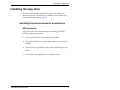
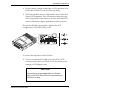
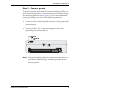
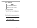
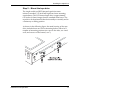
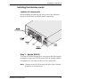
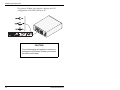
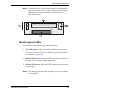
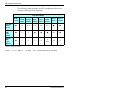
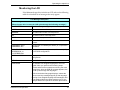
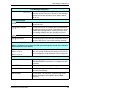
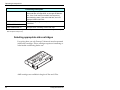
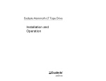
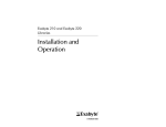
([DE\WH0DPPRWK Installation and Operation 306484-002 Copyright Copyright 1996–1999 by Exabyte Corporation. All rights reserved. This item and the information contained herein are the property of Exabyte Corporation. No part of this document may be reproduced, transmitted, transcribed, stored in a retrieval system, or translated into any language or computer language in any form or by any means, electronic, mechanical, magnetic, optical, chemical, manual, or otherwise, without the express written permission of Exabyte Corporation, 1685 38th Street, Boulder, Colorado 80301. Disclaimer Exabyte Corporation makes no representation or warranties with respect to the contents of this document and specifically disclaims any implied warranties of merchantability or fitness for any particular purpose. Further, Exabyte Corporation reserves the right to revise this publication without obligation to notify any person or organization of such revisions or changes. Trademark notices Exabyte, Exafacts, Exapak, Exasoft, and Exatape are registered trademarks of Exabyte Corporation. Arrowhead, Eliant, and SupportSuite are trademarks of Exabyte Corporation. All other product names are trademarks or registered trademarks of their respective owners. Revision history Revision Date Description 000 March 1996 Initial release. 001 July 1996 Update for new LCD information. 002 January 1999 Update for LVD SCSI configuration. Note: The most current information about this product is available at Exabyte’s web site (www.exabyte.com). Exabyte Corporation 1685 38th Street Boulder, Colorado 80301 (303) 442-4333 306484-002 ii Exabyte M ammoth Safety agency standards When purchased from Exabyte, both the internal model and the tabletop model of the Exabyte® Mammoth Tape Drive comply with the following domestic and international product safety standards: • UL Standard 1950, 1st Edition, Safety of Information Technology Equipment • CSA Standard C22.2 No. 950-95, Safety of Information Technology Equipment • IEC 950/EN60950: A4 1997, Safety of Information Technology Equipment including Electrical Business Equipment The internal model of the tape drive is certified as a component only. Certification of the final integrated product is the responsibility of the system integrator. Electromagnetic compatibility (EMC) When properly installed in a shielded cabinet with shielded cables and adequate grounding of the SCSI bus and input power, the tape drive meets the requirements for emissions and immunity as defined by the following standards: USA: FCC, CFR 47, Ch. I, Part 15, Subpart B, Class B Canada: ICES-003, Class B Australia: AS/NZ 3548, Class B Taiwan: CNS-13438, Class A Europe: EN55022/CISPR 22, Class B EN50082-1: Residential, Commercial, and Light Industry For the tabletop tape drive, the requirement for a shielded cabinet is met by the tabletop enclosure. Installation and Operation iii FCC notice When installed in an Exabyte enclosure, the tabletop model has been tested and found to comply with the limits for a Class B digital device pursuant to Part 15 of FCC rules. These limits are designed to provide reasonable protection against harmful interference in a residential installation. This equipment generates, uses, and can radiate radio frequency energy and, if not installed and used in accordance with the instructions, may cause interference to radio and television communications. However, there is no guarantee that interference will not occur in a particular installation. If this equipment does cause interference to equipment off and on, the user is encouraged to try to correct the interference by one or more of the following measures: • Reorient or relocate the receiving antenna. • Increase the separation between the equipment and receiver. • Connect the equipment into an outlet on a circuit different from that to which the receiver is connected. • Use shielded cables. • Consult the dealer or an experienced radio/TV technician for help. According to FCC regulations, changes or modifications not expressly approved by Exabyte Corporation could void your authority to operate the equipment. Industry Canada notice per ICES-003 iv This Class B digital apparatus meets all requirements of the Canadian Interference-Causing Equipment Regulations. Cet appareil numérique de la classe B respecte toutes les exigences du Règlement sur le matériel brouilleur du Canada. Exabyte M ammoth Contents Welcome . . . . . . . . . . . . . . . . . . . . . . . . . . . . . . . . . . . . . . . . . . . . . . . . . 1 Available SCSI configurations . . . . . . . . . . . . . . . . . . . . . . . . . . . . . . . 2 Installing the tape drive. . . . . . . . . . . . . . . . . . . . . . . . . . . . . . . . . . . . . 3 Installing the internal model in an enclosure . . . . . . . . . . . . . . . . . . . . . . 3 Installing the tabletop model . . . . . . . . . . . . . . . . . . . . . . . . . . . . . . . . . . 13 Operating the tape drive . . . . . . . . . . . . . . . . . . . . . . . . . . . . . . . . . . . 18 Monitoring the LEDs . . . . . . . . . . . . . . . . . . . . . . . . . . . . . . . . . . . . . . . . . Monitoring the LCD. . . . . . . . . . . . . . . . . . . . . . . . . . . . . . . . . . . . . . . . . . Selecting appropriate data cartridges . . . . . . . . . . . . . . . . . . . . . . . . . . . Loading data cartridges. . . . . . . . . . . . . . . . . . . . . . . . . . . . . . . . . . . . . . . Unloading data cartridges. . . . . . . . . . . . . . . . . . . . . . . . . . . . . . . . . . . . . Resetting the tape drive . . . . . . . . . . . . . . . . . . . . . . . . . . . . . . . . . . . . . . . Cleaning the tape drive . . . . . . . . . . . . . . . . . . . . . . . . . . . . . . . . . . . . . . . Using Tape Alert . . . . . . . . . . . . . . . . . . . . . . . . . . . . . . . . . . . . . . . . . . . . . 19 21 24 26 27 28 28 29 Packing the tape drive . . . . . . . . . . . . . . . . . . . . . . . . . . . . . . . . . . . . . 30 Appendix. . . . . . . . . . . . . . . . . . . . . . . . . . . . . . . . . . . . . . . . . . . . . . . . 31 Index . . . . . . . . . . . . . . . . . . . . . . . . . . . . . . . . . . . . . . . . . . . . . . . . . . 35 Installation and Operation v Notes vi Exabyte M ammoth Welcome Welcome Congratulations on selecting the Exabyte® Mammoth Tape Drive. Your new tape drive is designed for multimedia, imaging, transaction processing, large databases, and other storage-intensive applications. The Mammoth tape drive provides storage capacities of up to 20 gigabytes (GB) native on a single 170m data cartridge. The Mammoth tape drive is available as an internal model that can be installed into an enclosure (shown on the right) or as a tabletop model housed in its own enclosure (shown on the left). Installation and Operation 1 Available SCSI configurations Available SCSI configurations The Mammoth tape drive is available in the following fast SCSI-2 configurations: Narrow, single-ended Wide, single-ended Wide, high-voltage differential (HVD) Wide, low-voltage differential (LVD) The LVD tape drive uses an LVD interface that is Ultra and Ultra2 SCSI compatible. The LVD interface allows the tape drive to be placed on the same bus as Ultra and Ultra2 SCSI devices without slowing the performance of these devices. 2 Exabyte M ammoth Installing the tape drive Installing the tape drive If you have the internal model of the tape drive, follow the instructions below. If you have the tabletop model, follow the instructions beginning on page 13. Installing the internal model in an enclosure ESD protection Protect the tape drive from electrostatic discharge (ESD) by following these precautions: Use an antistatic mat and wristband, if possible. Leave the tape drive in its packaging until you are ready to install it. Touch a known grounded surface before handling the tape drive. Do not place the tape drive on a metallic surface. Installation and Operation 3 Installing the tape drive Location of components When installing the tape drive, refer to the following figures for the location of back-panel components. Narrow SCSI configuration: Wide SCSI configuration: 4 Exabyte M ammoth Installing the tape drive Step 1 – Set the SCSI ID To set the SCSI ID, remove and reposition the jumpers to obtain the desired ID. (If necessary, use a pair of flat-nose pliers to remove the jumpers.) The following figures show how to position the jumpers for narrow and wide SCSI configurations. Narrow SCSI configuration (SCSI IDs 0–7): If you need additional jumpers, use 0.1-inch jumpers for narrow SCSI (AMP part number 531220-2). Installation and Operation 5 Installing the tape drive Wide SCSI configuration (SCSI IDs 0–15): If you need additional jumpers, use 2 mm mini jumpers for wide SCSI (AMP part number 382575-2). Note: You can also set the SCSI ID by removing the jumpers and connecting your own remote switch. Step 2 – Connect the drive to the SCSI bus Before connecting the tape drive to the SCSI bus, be aware of the following: You can connect single-ended and LVD SCSI tape drives to the same SCSI bus. Be aware that mixing the two types of devices will result in all devices on the bus operating as single-ended devices. 6 Exabyte M ammoth Installing the tape drive Do not connect a single-ended wide or LVD tape drive to an HVD wide SCSI bus or your SCSI bus may hang. The LVD tape drive uses an LVD interface that is Ultra and Ultra2 SCSI compatible. The LVD interface allows the tape drive to be placed on the same bus as Ultra and Ultra2 SCSI devices without slowing the performance of these devices. The product ID label, shown below, displays the SCSI configuration: LVD, DIFF (HVD), or SE. To connect the tape drive to the SCSI bus: 1. Connect an internal SCSI cable to the tape drive’s SCSI connector and to the next SCSI device in the enclosure (for example, a SCSI adapter card). CAUTION Connecting a single-ended wide or LVD tape drive to an HVD wide SCSI bus may cause your SCSI bus to hang. Installation and Operation 7 Installing the tape drive 2. If the tape drive is the last device on the SCSI bus, you must terminate the bus by installing a pass-through terminator on the tape drive’s SCSI connector. Or, if there is an unused connector at the end of the SCSI cable, you can terminate the bus there. Use one of the terminator types listed in the following table. ➤ Important Exabyte recommends using active termination. Exabyte testing has shown that older passive termination does not provide rising edge transitions that are fast or clean enough at fast SCSI speeds. Narrow SCSI configuration Wide SCSI configuration AMP 750381-1 AMP 859516-1 HVD* N/A AMP 869515-1 LVD* N/A AMP 796051-1 Single-ended* * 8 Terminators for single-ended, HVD, and LVD buses are not identical. Do not mix the variants. Exabyte M ammoth Installing the tape drive Step 3 – Connect ground To protect the tape drive from electrostatic discharge (ESD), you must attach the tape drive to the enclosure’s metal chassis (using the mounting holes shown on page 11). If you need additional chassis grounding, use either of the following methods: Connect a 1/4-inch female spade connector to the ground tab (shown below). Connect an M3 × 0.5 × 6 mm self-tapping screw to the grounding hole (shown below). Note: The power supply returns are connected to the chassis, so you cannot isolate the logic common ground from the chassis ground. Installation and Operation 9 Installing the tape drive Step 4 – Connect pow er CAUTION Do not force the pow er cable into the tape drive’s power connector. If the power cable is upside dow n and you force the connection, you may damage the drive when you power it on. To connect power to the tape drive: 1. Connect the enclosure’s internal power cable to the tape drive’s power connector. (Use an AMP 1-480424-0 series or equivalent female power connector.) 2. Power on the enclosure. The tape drive performs its power-on self-test in about 30 seconds. When the tape drive is ready to accept a cartridge, the LEDs turn off. ➤ Important Do not insert a cartridge into the tape drive during the power-on self-test. The tape drive will eject the cartridge. 10 Exabyte M ammoth Installing the tape drive Step 5 – Mount the tape drive The single-ended and HVD internal tape drives meet industry-standard, 5.25-inch half-high form factor mounting requirements. The LVD internal tape drive is approximately 0.36 inches (9.2 mm) longer than the standard form factor. The tape drive can be mounted either horizontally or vertically and in a stationary or sliding position. As shown in the following figure, the main housing of the tape drive includes three sets of four mounting holes to allow for a number of mounting positions (two sets on the sides, set A and set B, and one set on the bottom, set C). Installation and Operation 11 Installing the tape drive When mounting the tape drive, follow these guidelines: Use one set of mounting holes. (Use all four holes in whichever set you choose; do not use combinations of mounting holes from different sets.) Use M3 × 0.5 × 6 mm screws. For proper mounting, use the correct screw length. Ensure that no objects such as screw heads, cables, or adjacent devices are pressing against the frame. Do not obstruct the ventilation slots on the bottom and at the rear of the tape drive. Allow sufficient space for accessing the tape drive’s front panel controls. 12 Exabyte M ammoth Installing the tape drive Installing the tabletop model Location of components When installing the tabletop tape drive, refer to the following figure for the location of the back-panel components. Step 1 – Set the SCSI ID To set the SCSI ID for the tape drive, use a pen or other fine-tipped instrument to press the SCSI ID switch until the desired number is displayed (0–7 for narrow SCSI or 0–15 for wide SCSI). Note: Changes in the SCSI ID setting take effect after a normal power-on or SCSI bus reset. Installation and Operation 13 Installing the tape drive Step 2 – Install the orientation pads The tabletop model includes adhesive pads that you must apply to either the base or the right side, depending on how you plan to position the tape drive. These pads protect the tape drive’s surface and allow air to flow through the vents when the tape drive is positioned on its side. To install the pads: 1. Remove the backing from four pads. (Five pads are shipped with the tape drive.) 2. Affix the pads to each corner, approximately 1/2-inch (1.3 cm) from the sides. For a horizontal orientation, place the pads on the bottom. For a vertical orientation, place the pads on the right side (the side with the external vents). 14 Exabyte M ammoth Installing the tape drive CAUTION If you want to position the tape drive on its side, you must place the pads on the right side. Otherwise, the air flow vents will be blocked and the enclosed tape drive will overheat. Step 3 – Connect the drive to the SCSI bus You may need to provide your own shielded SCSI cable; and if the tape drive is the last device on the bus, you may also need to provide an external terminator. See the appendix for cable and terminator requirements. Before connecting the tape drive to the SCSI bus, be aware of the following: You can connect single-ended and LVD SCSI tape drives to the same SCSI bus. Be aware that mixing the two types of devices will result in all devices on the bus operating as single-ended devices. Do not connect a single-ended wide or LVD tape drive to an HVD wide SCSI bus or your SCSI bus may hang. The LVD tape drive uses an LVD interface that is Ultra and Ultra2 SCSI compatible. The LVD interface allows the tape drive to be placed on the same bus as Ultra and Ultra2 SCSI devices without slowing the performance of these devices. Installation and Operation 15 Installing the tape drive The product ID label, shown below, displays the SCSI configuration: LVD, DIFF (HVD), or SE. CAUTION To avoid damaging the tape drive, make sure the tape drive is powered off w hen you connect the cables on the back. 16 Exabyte M ammoth Installing the tape drive To connect the tape drive to the SCSI bus: 1. Connect a shielded SCSI cable to the back of the tape drive. CAUTION Connecting a single-ended wide or LVD tape drive to an HVD w ide SCSI bus may cause your SCSI bus to hang. 2. If the tape drive is the last device on the SCSI bus, install a terminator on the other connector. If it is not the last device, connect another SCSI cable. Installation and Operation 17 Operating the tape drive Step 4 – Connect pow er To connect power to the tape drive: 1. Connect the power cord to the back. 2. Press the power switch to the on (l) position. The tape drive performs its power-on self-test in about 30 seconds. When the tape drive is ready to accept a cartridge, the LEDs turn off. ➤ Important Do not insert a cartridge into the tape drive during the power-on self-test. The tape drive will eject the cartridge. Operating the tape drive This section describes how to operate the tape drive. The figure below shows the front-panel components used for tape drive operation. 18 Exabyte M ammoth Operating the tape drive Note: In addition to the LEDs, some models of the Mammoth tape drive include an LCD (shown below) that displays alphanumeric information about the tape drive’s operational status. Monitoring the LEDs The LEDs have the following, general meanings: Top LED (amber). When this LED is flashing, an error has occurred. When this LED is on solid, the tape drive needs to be cleaned (see page 28). Middle LED (green). When this LED is on, tape is loaded and the tape drive is ready to begin operations. Bottom LED (green). When this LED is flashing, tape motion is occurring. Note: The tabletop tape drive also includes a power-on LED on its front panel. Installation and Operation 19 Operating the tape drive The following table describes the LED combinations that occur during normal tape drive operation. Tape Drive State * POST* or reset Error or failed POST Ready (no tape loaded) Ready (tape loaded) Normal tape motion High speed motion Time to clean Clean in progress Top LED (Error/ Clean) ● ❊ n/a n/a n/a n/a ● ● Middle LED (Tape Ready) ● ❍ ❍ ● ● ● n/a ● Bottom LED (Tape Motion) ● ❍ ❍ ❍ ❊ n/a ❊ ❊ fast POST = power-on self-test Legend: 20 ❍ = off ● = on ❊= flash n/a = not applicable (may be any state) Exabyte M ammoth Operating the tape drive Monitoring the LCD If the Mammoth tape drive includes an LCD, refer to the following table for a detailed list of messages that may appear. LCD M essage Description* Reset messages. (When the tape drive is reset, the LCD cycles through the follow ing messages.) * * * RESETTING The first message during the power-on sequence. MODEL: The model number of the tape drive. SUBMOD: The submodel number of the tape drive. SN: The serial number of the tape drive. CODE: The level of the tape drive’s firmware. LAST CLN: nn hrs The number of hours since the tape drive has last been cleaned. COMPRESS: ON or COMPRESS: OFF Compression is enabled (the default) or compression is disabled. SINGLE-ENDED or DIFFERENTIAL or LV DIFFERENTIAL The tape drive has a single-ended, differential (HVD), or LVD SCSI configuration. WIDE or NARROW The tape drive has a wide or narrow SCSI configuration. SCSI ID: The SCSI ID of the tape drive. LANGUAGE: The available non-English languages for the LCD appear when you perform the following steps: 1. Press and hold the unload button during the reset sequence. After the SCSI ID message appears, the LCD cycles through the languages. 2. When the desired language displays, release the button and the messages appear in that language. For a list of non-English language LCD messages, refer to the Exabyte Web site (www.exabyte.com) or the Exabyte M ammoth Tape Drive Product Specification. Installation and Operation 21 Operating the tape drive LCD M essage Description* Tape drive status messages READY–NOTAPE The tape drive is ready to accept a cartridge. LOADING . . . . The tape drive is loading the tape. READY–TAPE The tape drive has successfully loaded the tape and is ready for read/write operations. EJECT ■■■= = = The unload button was pressed. The tape drive ejects the cartridge as soon as it finishes its current operation. The icon to the left of the EJECT message indicates the current operation (write, erase, and so on). EJECT–PREVNT The software has disabled the eject function with the PREVENT/ALLOW MEDIA REMOVAL command. The tape drive will rewind and unload the tape, but will not eject the cartridge. ILLEGAL TAPE The tape drive detected an incompatible cartridge and ejected it. Tape motion messages READ + ■■■= = = WRITE+ ■■■= = = The tape drive is reading or writing data. The + sign appears when the tape drive is in compression mode. The boxes show the amount of tape used. PROTECTED The tape drive cannot write data because the data cartridge is write-protected. ILLEGAL WRT The tape drive cannot write to the type of data cartridge inserted. This message remains until an unload/eject operation is performed. >> << SEARCH ■■= = = = SEARCH ■■= = = = High-speed search is in progress. The arrows indicate the direction of the search. << REWIND ■■= = = = Rewind is in progress. ERASE ■■= = = = The tape drive is erasing data on the tape. 22 Exabyte M ammoth Operating the tape drive LCD M essage Description* FORMAT ■■■■■■ The tape drive is repartitioning the tape to the requested format. The icon to the left of the message displays the current operation (write, erase, search, and so on). Cleaning messages CLEAN SOON The tape drive should be cleaned at the next convenient time. MUST CLEAN The tape drive must be cleaned after a metal particle tape has been used in the drive. If you attempt to insert an AME data cartridge before cleaning the tape drive, this message displays and the cartridge is ejected. CLEANING . . . Cleaning is in progress. DEPLETED The cleaning tape in the cartridge is depleted and the tape drive will eject it. Use a new cleaning cartridge. Error conditions (When a hardw are error occurs, the LCD cycles through the current error code and the previous tw o error codes.) ERR 1: xx yy zz ERR 2: xx yy zz ERR 3: xx yy zz In the error display, xx indicates the fault symptom code, and yy and zz indicate secondary errors (if any). If an error appears, contact Exabyte Technical Support. Diagnostics and loading code DIAG-LOAD TAPE This message appears if the tape drive receives a SCSI SEND DIAGNOSTIC command or if a diagnostic tape is inserted. DIAG-TESTING.... The tape drive is performing the diagnostic tests. DIAG-PASSED This message appears for 15 seconds when the test completes successfully. DIAG-FAILED The test failed. The LCD then cycles through three statistics messages: DIAG-WRITE, DIAG-READ, DIAG-ECC. Installation and Operation 23 Operating the tape drive LCD M essage Description* LOADING CODE.... This message displays when code is loading from a code load tape, through SCSI, or through the Monitor port. If the code load is successful, the tape drive automatically resets. If the code load fails, the LCD displays CODE LOAD FAIL. CODE LOAD FAIL These messages appear in sequence after the code load failed. RETRY CODE LOAD MAKE CODELOAD TP * The tape drive is making a code load tape. These are the correct messages as of January 1999. You can find updated LCD messages on Exabyte’s Web site (www.exabyte.com). Selecting appropriate data cartridges For writing data, use only Exatape™ advanced metal evaporated (AME) data cartridges. These cartridges require no formatting or other media conditioning before use. AME cartridges are available in lengths of 22m and 170m. 24 Exabyte M ammoth Operating the tape drive Using metal particle tapes The tape drive can read data from metal particle (MP) tape when it is written in one of the following formats: 8500c, 8500, or 8200. (The tape drives cannot read data written in 8200c format.) If you insert an AME cartridge after reading MP tape, you must clean the tape drive (see page 28). ➤ Important Mammoth can read data written on metal particle tape, but it cannot w rite to this type of tape. Installation and Operation 25 Operating the tape drive Loading data cartridges To load a cartridge: 1. Make sure the tape drive is ready to accept a cartridge (all LEDs are off). Do not insert a cartridge if the tape drive is still performing its power-on self-test. 2. Set the write-protect switch for the desired operation (shown below). 26 Exabyte M ammoth Operating the tape drive 3. Insert the cartridge as shown in the following figure. The tape drive loads the tape in approximately 20 seconds. When the middle LED is on, the tape drive is ready for read and write operations. Unloading data cartridges To unload a cartridge, press the unload button. Do not press and hold the unload button for more than 10 seconds; this can cause a reset under certain conditions. If the tape drive is free of errors, it performs the following actions in about one minute: Completes any command in process Writes any buffered information to tape Rewinds the tape to the beginning Unloads the tape and ejects the cartridge Note: If an error occurs before or during the unload procedure, the tape drive suspends the unload sequence. To clear the error, press the unload button again. The tape drive reattempts the unload sequence, but does not write data in the buffer. Installation and Operation 27 Operating the tape drive Resetting the tape drive To reset the tape drive, press and hold the unload button for at least 10 seconds, or power the drive off and back on again. Note: If you reset the tape drive while a cartridge is loaded, it rewinds the tape to the beginning after the reset is complete. The reset may take as long as two minutes if the tape is positioned near the end. Cleaning the tape drive When manual cleaning is required, the top LED turns on. To help maintain data integrity and reliability, you should manually clean the tape drive as soon as possible after the LED turns on. ➤ Important When you insert an AME cartridge after reading MP tape, the top LED turns on and the cartridge is ejected. Before you can use the AME tape, you must clean the tape drive as described below . To clean the tape drive, insert an Exabyte Mammoth 8mm Cleaning Cartridge (or a cleaning cartridge approved by Exabyte for use with Mammoth). When finished, the tape drive turns off the top LED and ejects the cleaning cartridge. 28 Exabyte M ammoth Operating the tape drive About the dynamic head cleaner The Exabyte Mammoth features an integrated dynamic head cleaner (cleaning wheel) for automatic self-cleaning of the recording heads and scanner. The cleaning wheel is activated every time media is loaded or unloaded. In addition, a sophisticated algorithm contained in the tape drive’s firmware can invoke the cleaning wheel if needed during extended backup or restore operations. The self-cleaning action of the dynamic head cleaner typically extends the interval between manual cleanings. The interval depends on the number of tape motion hours and the type of tape being used (MP or AME). Using Tape Alert Tape Alert provides a standardized method for reporting errors and potential difficulties with the tape drive and media. The tape drive’s internal Tape Alert firmware constantly monitors the tape drive and the media for errors and potential difficulties that could have an impact on backup quality. Any problems identified are flagged on the Tape Alert SCSI log page. When the tape drive is used with Tape Alert-compatible backup software, the software automatically reads the log page after the completion of each backup. If an error is flagged, the backup software displays a clear warning message, suggests a corrective action for the problem, and adds the Tape Alert messages to its logs. Installation and Operation 29 Packing the tape drive Packing the tape drive If you are shipping the tape drive to another location or returning it for repair, pack the tape drive in its original shipping container and packing materials. CAUTION To avoid damaging the tape drive and voiding your warranty, use the original shipping materials (or replacement materials from your dealer). ➤ Important If you are returning the tape drive for service, remove and keep all cartridges, cables, and terminators. If you are returning the tape drive to the factory for service, contact your service provider. If your service provider instructs you to return the tape drive directly to Exabyte, contact Exabyte Service (1-800-EXATAPE) to obtain a Return Materials Authorization (RMA) number and the shipping address. 30 Exabyte M ammoth Appendix Appendix Specifications Maximum Data Capacity Tape Length Compressed Data* Uncompressed Data 22m 5 gigabytes 2.5 gigabytes 170m 40 gigabytes 20 gigabytes * Assumes a 2: 1 compression ratio. Maximum Data Transfer Rates * Compressed data* 6 MB/sec. Uncompressed data 3 MB/sec. Assumes a 2: 1 compression ratio. Operating Environment Specifications Tape Path Temperature Range + 5° C to + 45° C (+ 41° F to + 104° F) Relative Humidity 20% to 80%; non-condensing Wet Bulb 26° C (79° F) max Altitude –304.8 m to + 3,048 m (–1,000 ft to + 10,000 ft) Installation and Operation 31 Appendix Input Voltages Internal model Standard + 5 VDC and + 12 VDC ± 5% Tabletop model Accepts 120 or 240 VAC at 50 to 60 Hz. Automatic input voltage selection. SCSI Cable Specifications — Internal M odel Connector type Narrow 50-pin female, shielded, AMP 1-746285-0 Wide 68-pin male, shielded, AMP 786090-7 Length (maximum) 32 Single-ended 3 meters (9.8 feet)* HVD/LVD 25 meters (82 feet)† * A maximum cable length of 6 meters is acceptable if the transfer rate is less than 5 MB/sec. † The maximum length for any one cable is 12 meters (39 feet). Exabyte M ammoth Appendix SCSI Cable Specifications — Tabletop M odel Connector type Narrow 50-pin male, high-density, shielded, AMP 750681-1 Wide 68-pin male, high-density, shielded, AMP 750752-1 Total maximum length (terminator to terminator)* Single-ended 3 meters (9.8 feet)† HVD/LVD 25 meters (82 feet)‡ * Each tabletop tape drive attached to the SCSI bus uses 0.4 meters (1.31 feet) of cable length internally. To determine the total length, add 0.4 meters (1.31 feet) to the length of cable used on the bus for each tabletop tape drive. † A maximum cable length of 6 meters is acceptable if the transfer rate is less than 5 MB/sec. ‡ If you have more than two devices on the bus, the maximum length for any one cable is 12 meters (39 feet). Terminator Specifications — Tabletop Model Narrow, single-ended AMP 750381-1 Wide Single-ended AMP 869516-1 HVD AMP 869515-1 LVD AMP 796051-1 Installation and Operation 33 Appendix Notes 34 Exabyte M ammoth Index $ agency standards iii altitude specifications 31 AME tape 24 % back panel internal model 4 tabletop model 13 & cable See SCSI cable cartridges data capacity 31 loading 26 types to use 24 unloading 27 using AME tape 24 using metal particle tape 25 cleaning dynamic head cleaner 29 LED indicator 19–20 procedure 28 code level of tape drive 21 compression mode 21 Installation and Operation ' data capacity 31 data cartridges See cartridges data format 25 differential 6 ( eject button See unload button environmental specifications 31 error conditions displayed on LCD 23 displayed on LEDs 20 ESD protection 3, 9 ) front panel components 18 * grounding the internal model 9 + high-voltage differential (HVD) 2, 7 humidity specifications 31 35 Index , 3 input voltages 32 installation internal model 3–12 tabletop model 13–18 packing the tape drive 30 performance specifications 31 power connecting for internal model 10 connecting for tabletop model 18 / LCD changing the displayed language 21 location 19 status messages 21–23 LEDs location 19 power-on LED for tabletop 19 status messages 19–20 low-voltage differential (LVD) 6 0 media See cartridges metal particle (MP) tape, cleaning requirements after use 25 mounting the internal model 11–12 2 orientation pads for tabletop model 14 36 5 remote switch 6 resetting the tape drive 28 returning the tape drive 30 6 safety agency standards iii screws for mounting 12 SCSI bus connecting to internal model 6 connecting to tabletop model 15 SCSI cable specifications for internal model 32 specifications for tabletop model 33 SCSI configurations 2 SCSI ID displayed on LCD 21 setting for internal model 5–6 setting for tabletop model 13 serial number of tape drive 21 shipping the tape drive 30 single-ended 2, 6 specifications 31–33 Exabyte M ammoth Index 7 tape See cartridges Tape Alert 29 tape motion LED 19–20 tape ready LED 19–20 temperature specifications 31 termination internal model 8 tabletop model 17, 33 transfer rates 31 8 unload button location 18 used for resetting tape drive used for unloading cartridges 27 28 9 voltages 32 Installation and Operation 37 Index Notes 38 Exabyte M ammoth