1
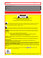
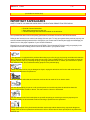
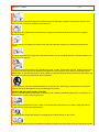
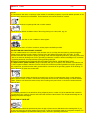
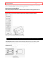
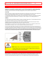
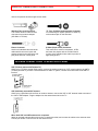
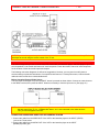
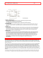
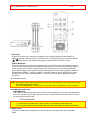
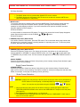
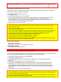
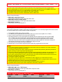
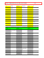
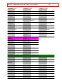
IMPORTANT
-1-
PROJECTION COLOR TV
50UX58B - 50UX58K
60UX58B - 60UX58K
55UX58B
OPERATING GUIDE
TABLE OF CONTENTS
IMPORTANT ..............................................................................................................................2
SAFETY TIPS.............................................................................................................................3
PICTURE CAUTIONS.............................................................................................................6
ACCESSORIES..........................................................................................................................7
REMOTE CONTROL BATTERY INSTALLATION AND REPLACEMENT..............................7
HOW TO SET UP YOUR NEW HITACHI PROJECTION TV .....................................................8
HOOK-UP CABLES AND CONNECTORS.................................................................................8
ANTENNA CONNECTIONS TO REAR JACK PANEL............................................................9
FRONT PANEL CONTROLS....................................................................................................10
FRONT VIEW .......................................................................................................................10
FRONT PANEL JACKS AND CONNECTIONS ........................................................................11
REAR PANEL JACKS ..............................................................................................................11
REAR PANEL CONNECTIONS ...............................................................................................12
TIPS ON REAR PANEL CONNECTIONS.............................................................................12
EXTERNAL CONNECTIONS ...................................................................................................12
CONNECTING EXTERNAL AUDIO AMPLIFIER..................................................................12
CONNECTING EXTERNAL VIDEO SOURCES.......................................................................13
CONNECTING A STEREO VCR OR STEREO LASERDISC PLAYER................................14
CONNECTING A STEREO LASERDISC PLAYER OR DVD PLAYER TO INPUT 2............14
AUDIO SYSTEM SETUP .........................................................................................................15
THE GENIUS REMOTE CONTROL (CLU-612MP)..................................................................15
MULTI-PAGE WINDOWS.........................................................................................................16
HOW TO USE THE GENIUS REMOTE TO CONTROL YOUR TV ..........................................17
PICTURE-IN-PICTURE (PIP) ...................................................................................................18
USING THE REMOTE TO CONTROL VCR FUNCTIONS .......................................................20
USING THE REMOTE TO CONTROL CABLE BOX/SATELLITE FUNCTIONS ......................21
USING THE REMOTE TO CONTROL AUDIO EQUIPMENT FUNCTIONS.............................22
AUDIO, CABLE/SATELLITE, AND VCR CODES.....................................................................22
ULTRATEC OSD......................................................................................................................27
SET UP ....................................................................................................................................29
CUSTOM..................................................................................................................................31
VIDEO ......................................................................................................................................36
AUDIO ......................................................................................................................................37
THEATER.................................................................................................................................39
INFO.........................................................................................................................................40
CARE OF YOUR HITACHI PROJECTION TV AND YOUR REMOTE CONTROL...................42
IMPORTANT
-2-
RECEPTION PROBLEMS........................................................................................................42
USEFUL INFO..........................................................................................................................43
Back Cover ...............................................................................................................................45
WARRANTY .............................................................................................................................45
IMPORTANT
Follow all warnings and instructions marked on this projection television.
CAUTION: TO REDUCE THE RISK OF ELECTRIC SHOCK,
DO NOT REMOVE COVER (OR BACK).
NO USER-SERVICEABLE PARTS INSIDE.
REFER SERVICING TO QUALIFIED SERVICE PERSONNEL.
The lightning flash with arrowhead symbol, within an equilateral triangle, is intended to alert the user to
the presence of uninsulated "dangerous voltage" within the product's enclosure that may be of sufficient
magnitude to constitute a risk of electric shock to persons.
The exclamation point within an equilateral triangle is intended to alert the user to the presence of
important operating and maintenance (servicing) instructions in the literature accompanying the appliance.
WARNING:
TO PREVENT FIRE OR SHOCK HAZARD, DO NOT EXPOSE THIS TELEVISION SYSTEM TO RAIN OR
MOISTURE.
NOTE: • There are no user serviceable parts inside the television.
• Model number and serial number are indicated on back side of the television.
• This television is not intended for use in a computer room.
CAUTION: Adjust only those controls that are covered in the instructions, as improper changes or
modifications not
expressly approved by HITACHI could avoid the user's authority to operate the TV
POWER SOURCE:
This projection television is designed to operate on 120 volts 60 Hz, AC household current.
Insert power cord into a 120 volt 60 Hz outlet.
TO PREVENT ELECTRIC SHOCK, DO NOT USE THE TELEVISION'S PLUG WITH AN EXTENSION CORD,
RECEPTACLE, OR OTHER OUTLET UNLESS THE BLADES AND GROUND TERMINAL CAN BE FULLY
INSERTED TO PREVENT BLADE EXPOSURE.
NEVER CONNECT THE TV TO 50 Hz, DIRECT CURRENT, OR ANYTHING OTHER THAN THE SPECIFIED
VOLTAGE.
NOTE: This television receiver will display television closed captioning (
paragraph 15, 119 of the FCC rules.
or
), in accordance with
CAUTION: Never remove the back cover of the television as this can expose you to very high
voltages and other hazards. If the set does not operate properly, unplug the set and call
SAFETY TIPS
-3your dealer or service shop.
SAFETY TIPS
IMPORTANT SAFEGUARDS
SAFETY POINTS YOU SHOULD KNOW ABOUT YOUR HITACHI PROJECTION TELEVISION
CAUTION:
• Read all of these instructions.
• Save these instructions for later use.
• Follow all warnings and instructions marked on the television.
Our reputation has been built on the quality, performance, and ease of service of HITACHI televisions.
Safety is also foremost in our minds in the design of these units. To help you operate these products properly, this
section illustrates safety tips which will be of benefit to you. Please read it carefully and apply the knowledge you
obtain from it to the proper operation of your HITACHI television.
Please fill out your warranty card and mail it to HITACHI. This will enable HITACHI to notify you promptly in the
improbable event that a safety problem should be discovered in your product model.
FOR YOUR PERSONAL SAFETY
1 This television is equipped with a polarized alternating-current line plug (a plug having one blade wider than the
other). This plug will fit into the power outlet only one way. This is a safety feature. If you are unable to insert the
plug fully into the outlet, try reversing the plug. If the plug should still fail to fit, contact your electrician to replace
your obsolete outlet. Do not defeat the safety purpose of the polarized plug.
2 When the power cord or plug is damaged or frayed, unplug this television set from the wall outlet and refer
servicing to qualified service personnel.
3 Do not overload wall outlets and extension cords as this can result in fire or electric shock.
4 Do not allow anything to rest on or roll over the power cord, and do not place the television where the
power cord is subject to traffic or abuse. This may result in a shock or fire hazard.
5 Do not attempt to service this television set yourself as opening or removing covers may expose you to
dangerous voltage or other hazards. Refer all servicing to qualified service personnel.
6 Never push objects of any kind into this television set through cabinet slots as they may touch dangerous
voltage points or short out parts that could result in a fire or electric shock. Never spill liquid of any kind on the
television set.
SAFETY TIPS
-4-
7 If the television has been dropped or the cabinet has been damaged, unplug this television set from the wall
outlet and refer servicing to qualified service personnel.
8 If liquid has been spilled into this television set, unplug it from the wall outlet and refer service to qualified
service personnel.
9 Do not subject your television to impact of any kind. Be particularly careful not to damage the picture tube
surface.
10 Unplug this television from the wall outlet before cleaning. Do not use liquid cleaners or aerosol cleaners. Use
a damp cloth for cleaning.
11-1 Do not place the television on an unstable cart, stand, or table. The television may fall, causing serious injury
to a child or an adult, and serious damage to the appliance. Use only with a cart or stand recommended by the
manufacturer, or sold with the television. Wall or shelf mounting should follow the manufacturer's instructions, and
should use a mounting kit approved by the manufacturer.
11-2 An appliance and cart combination should be moved with care. Quick stops, excessive force, and uneven
surfaces may cause the appliance and cart combination to overturn.
PROTECTION AND LOCATION OF YOUR SET
12 Do not use this television near water, for example, near a bathtub, washbowl, kitchen sink, or laundry tub, in a
wet basement, or near a swimming pool, etc.
• Never expose the television to rain or water. If the set has been exposed to rain or water, unplug the set from
the wall outlet and refer servicing personnel.
13 Choose a place where light (artificial or sunlight) does not shine directly on the screen.
14 Avoid dusty places, since accumulated dust inside the chassis may cause failure of the set when high humidity
SAFETY TIPS
-5-
persists.
15 The television has slots, or openings in the cabinet for ventilation purposes, to provide reliable operation of the
receiver, and to protect from overheating. These openings must not be blocked or covered.
• Never cover the slots or openings with cloth or other material.
• Never block the bottom ventilation slots of the set by placing it on a bed, sofa, rug, etc.
• Never place the set near or over a radiator or heat register.
• Never place the set in a "built-in" enclosure, unless proper ventilation provided.
PROTECTION AND LOCATION OF YOUR SET
16-1 If an outside antenna is connected to the television set, be sure the antenna system is protected against
voltage surges and built up static charges, Section 810 of the National Electrical Code, NFPA No. 70-1975,
provides information with respect to proper grounding of the mast and supporting structure, grounding of the leadin wire to an antenna discharge unit, size of grounding conductors, location of antenna discharge unit, connection
to grounding electrode, and requirements for the grounding electrode.
ANTENNA GROUNDING DIAGRAM AS PER NATIONAL ELECTRICAL CODE INSTRUCTIONS .
16-2 Note to CATV system installer: (Only for television with CATV reception) This reminder is provided to call
the CATV system installer's attention to Article 820-40 of the NEC that provides guidelines for proper grounding
and, in particular, specifies that the cable ground shall be connected to the grounding system of the building, as
close to the point of cable entry as practical.
17 An outside antenna system should not be located in the vicinity of overhead power lines or other electrical
lights or power circuits, or where it can fall into such power lines or circuits. When installing an outside antenna
system, extreme care should be taken to keep from touching such power lines or circuits as contact with them
might be fatal.
18 For added protection for the television during a lightning storm, or when it is left unattended and unused for
long periods of time, unplug it from the wall outlet and disconnect the antenna. This will prevent damage due to
lightning and power-line surges.
OPERATION OF YOUR SET
19 This television should be operated only from the type of power source indicated on the marking label. If you
are not sure of the type of power supply at your home, consult your television dealer or local power company. For
television sets designed to operate from battery power, refer to the operating instructions.
SAFETY TIPS
-6-
20 If the television does not operate normally by following the operating instructions, unplug this set television set
from the wall outlet and refer servicing to qualified service personnel. Adjust only those controls that are covered
in the operating instructions as improper adjustment of other controls may result in damage and will often require
extensive work by a qualified technician to restore the television set to normal operation.
21 If your television is to remain unused for a period of time, (such as when going on a holiday), turn the television
OFF and unplug it from the wall outlet.
IF THE TELEVISION DOES NOT OPERATE PROPERLY
22 If you are unable to restore normal operation by following the detailed procedure in your operating instructions,
do not attempt any further adjustment. Unplug the television and call your dealer or service technician.
23 Whenever the television is damaged or fails, or a distinct change in performance indicates a need for service,
unplug the set and have it checked by a professional service technician.
24 It is normal for some televisions to make occasional snapping or popping sounds, particularly when being
turned on or off. If the snapping or popping is continuous or frequent, unplug the set and consult your dealer or
service technician.
FOR SERVICING AND MODIFICATION
25 Do not use attachments not recommended by the television set manufacturer as they may cause hazards.
26 When replacement parts are required, be sure the service technician has used replacement parts specified by
the manufacturer that have the same characteristics as the original part. Unauthorized substitutions may result in
fire, electric shock, or other hazards.
27 Upon completion of any service or repairs to the television set, ask the service technician to perform routine
safety checks to determine that the television is in safe operating condition.
PICTURE CAUTIONS
Picture Burn Prevention
• Continuous on-screen displays such as video games, stock market quotations, computer generated graphics,
and other fixed (non-moving) patterns can cause permanent damage to projection television receivers. Such
"PATTERN BURNS" constitute misuse and are NOT COVERED by your HITACHI Factory Warranty.
ACCESSORIES
-7-
• When using Picture-in-Picture function, the sub-picture should not be left permanently in one corner of the
screen or a "PATTERN BURN" may develop over a long period of time.
Public Viewing of Copyrighted Material
Public viewing of programs broadcast by TV stations and cable companies, as well as programs from other
sources, may require prior authorization from the broadcaster or owner of the video program material.
ACCESSORIES
Check to make sure you have the following accessories before disposing of the packing material.
1. Remote Control Unit CLU-612MP (Part No. HL00712)
2. Two "AA" size, 1.5V batteries (For Remote Control Unit).
REMOTE CONTROL BATTERY INSTALLATION AND REPLACEMENT
1. Open the battery cover of the remote control by pushing the notched part of the cover with your fingers
and pulling the cover off.
2. Insert two new "AA" size batteries for the remote control. When replacing old batteries, push them
towards the springs and lift them out.
3. Match the batteries to the (+) and (-) marks in the battery compartment.
4. Replace the cover.
BOTTOM VIEW
HOW TO SET UP YOUR NEW HITACHI PROJECTION TV
-8-
HOW TO SET UP YOUR NEW HITACHI PROJECTION TV
ANTENNA
Unless your TV is connected to a cable TV system or to a centralized antenna system, a good outdoor color TV
antenna is recommended for the best performance. However, if you are located in an exceptionally good signal
area that is free from interference and multiple image ghosts, an indoor antenna may be sufficient.
LOCATION
Select an area where sunlight or bright indoor illumination will not fall directly on the picture screen. Also, be sure
that the location selected allows free flow of air to and from the perforated back cover of the set.
To avoid cabinet warping, cabinet color changes, and increased chance of set failure, do not place the TV where
temperatures can become excessively hot, for example, in direct sunlight or near a heating appliance, etc.
VIEWING
The major benefit of the HITACHI Projection Television is its large viewing screen. To see this large screen at its
best, test various locations in the room to find the best spot for viewing.
The best picture is seen by sitting directly in front of the TV and about 10 to 18 feet from the screen. Picture
brightness decreases as the viewer moves to the left or right of the receiver.
During daylight hours, reflections from outside light may appear on the screen. If so, drapes or screens can be
used to reduce the reflection or the TV can be located in a different section of the room.
If the TV's audio output will be connected to a Hi-Fi system's external speakers, the best audio performance will
be obtained by placing the speakers equidistant from each side of the receiver cabinet and as close as possible to
the height of the picture screen center. For best stereo separation, place the external speakers at least 4 feet from
the side of the TV. Place the surround speakers to the side or behind the viewing area. Differences in room sizes
and acoustical environments will require some experimentation with speaker placement for best performance.
CAUTION: Magnetic fields, such as those of external speakers, may cause the picture to
distort if
they are placed too close to the television. Move the magnetic field source away from
the television until there is no picture distortion.
HOOK-UP CABLES AND CONNECTORS
Most video/audio connections between components can be made with shielded video and audio cables that have
phono connectors. For best performance, video cables should use 75-Ohm coaxial shielded wire. Cables can be
purchased from most stores that sell audio/video products. Below are illustrations and names of common
connectors. Before purchasing any cables, be sure of the output and input connector types required by the
HOOK-UP CABLES AND CONNECTORS
-9-
various components and the length of each cable.
300-Ohm Twin Lead Connector
This outdoor antenna cable must be
connected to an antenna adaptor
(300-Ohm to 75-Ohm).
"F" Type 75-Ohm Coaxial Antenna Connector
For connecting RF signals (antenna or cable TV)
to the antenna jack on the television.
Phono Connector
Used on all standard video and audio
cables which connect to inputs and
outputs located on the television's rear
jack panel and front control panel.
S-Video (Super Video) Connector
This connector is used on camcorders, VCRs,
and laser disc players with an S-Video feature
in place of the standard video cable to produce a
high-quality picture.
ANTENNA CONNECTIONS TO REAR JACK PANEL
VHF (75-Ohm) antenna/CATV(cable TV)
When using a 75-Ohm coaxial cable system, connect the outdoor antenna or CATV coaxial cable to the ANT A
(75-Ohm) terminal. If you have a second antenna or cable TV system, connect the coaxial cable to the ANT B
terminal.
VHF (300-Ohm) antenna/UHF antenna
When using a 300-Ohm twin lead from an outdoor antenna, connect the VHF or UHF antenna leads to screws of
the VHF or UHF adaptor. Plug the adaptor into the antenna terminal on the TV.
When both VHF and UHF antennas are connected
Attach an optional antenna cable mixer to the TV antenna terminal, and connect the cables to the antenna mixer.
Consult your dealer or service store for the antenna mixer.
FRONT PANEL CONTROLS
- 10 -
FRONT PANEL CONTROLS
FRONT VIEW
Front Panel Diagram Illustration
1 MENU button
This button allows you to enter the MENU, making it possible to set TV features to your preference
without using the remote.
2 INPUT/EXIT button
Press this button to select the current antenna source, VIDEO: 1, 2, 3 or alternate antenna source. Your
selection is shown in the top right corner of the screen. This button also serves as the EXIT button
when
in MENU mode.
3 CHANNEL selector
Press these buttons until the desired channel appears in the top right corner of the TV screen. These
buttons also serve as the cursor down (
) and up ( ) buttons when in MENU mode.
4 VOLUME level
Press these buttons for your desired sound level. The volume level will be displayed on the TV screen.
These buttons also serve as the cursor left (
) and right ( ) buttons when in MENU mode.
5 POWER button
Press this button to turn the TV on or off.
NOTE: Your HITACHI Projection TV will appear to be turned OFF if there is no video input when VIDEO:
1, 2 or 3 is selected. Check the Power Light to make sure the TV is off when not in use.
To see an auto-demonstration of the on-screen displays with HELP text displayed, press and hold
the
POWER button on the TV set for approximately five seconds. Press the POWER button on the TV
again to end the auto-demonstration.
6 POWER light
You will see a red light when the TV is turned on.
7 AI (Artificial Intelligence) sensor
The Artificial Intelligence sensor will make automatic picture adjustments depending on the amount of
light in the room to give the best picture. (See page 49.)
8 REMOTE CONTROL sensor
Point your remote at this area when selecting channels, adjusting volume, etc.
9 MAGIC FOCUS
Use this button to adjust your picture quality to optimum performance. (See page 40.)
10 FRONT INPUT JACKS (for VIDEO: 3)
Use these audio/video jacks for a "quick" hook-up from a camcorder or VCR to instantly view your
favorite show or new recording. Press the INPUT button until VIDEO: 3 appears in the top right
corner of the TV screen. If you have mono sound, insert the audio cable in to the left channel jack.
FRONT PANEL JACKS AND CONNECTIONS
- 11 -
FRONT PANEL JACKS AND CONNECTIONS
The front panel jacks are provided as a convenience to allow you to easily connect a camcorder or VCR as shown
in the following examples:
Front Panel Jacks and Connections Illustration
NOTE: Completely insert connection cord plugs when connecting to front panel jacks. If you do not, the
played back picture may be abnormal. If you have a S-VHS VCR, use the S-INPUT cable in place
of the standard video cable.
If you have mono VCR, insert the audio cable into the left channel jack.
REAR PANEL JACKS
Rear Panel Jacks Illustration
1 Antenna Input/Output
The remote control allows you to switch between two separate 75-Ohm RF antenna inputs, ANT A and
ANT B. ANT A input can be displayed as a main picture or sub-picture. ANT B can only be displayed
as a main picture. (ANT B cannot be displayed as a sub-picture.) The antenna output labeled "TO
CONVERTER" allows the ANT A connection to pass directly to a different source such as a cable box,
when ANT B is displayed as a main picture.
2 Audio/Video Inputs 1, 2
The INPUT button will step through each video source and antenna source input each time it is pressed.
Use the audio and video inputs to connect external devices, such as VCRs, camcorders, laserdisc
players, etc. (If you have mono sound, insert the audio cable into the left channel jack.)
Note: You may use VIDEO, S-VIDEO, or COMPONENT: Y-CbCr inputs to connect to Input 2, note
that only one of these may be used at a time.
3 Monitor Out
These jacks provide fixed audio and video signals which are used for recording.
4 Wireless Out
These jacks provide variable audio output to a set of wireless speakers. They can also be used for
another stereo system amplifier. With this connection, the audio can be controlled by the television's main
volume and also by an independent volume feature found in the THEATER-WIRELESS SOUND menu.
5 Audio to Hi-Fi
These jacks provide variable audio output to a separate stereo amplifier. With this connection, the audio
to the stereo can be controlled by the television's main volume. Use these jacks for the SURROUND
Left and Right channels. (See page 17.)
6 S-Video Inputs 1 and 2
Inputs 1 and 2 provide S-Video (Super Video) jacks for connecting equipment with S-Video output
capability.
7 Component: Y-CbCr Input 2
Input 2 provides Y-CbCr jacks for connecting equipment with this capability, such as a DVD player.
Note: DO NOT connect standard VIDEO or S-VIDEO to Input 2 when using Y-CbCr input.
When using the Y-CbCr input jacks, connect your components audio output to the TV's Input 2
Left and Right Audio input jacks.
Your component outputs may be labeled Y, B-Y, and R-Y. In this case, connect the components
B-Y output to the TV's Cb input and the components R-Y output to the TV's Cr input.
It may be necessary to adjust TINT or turn AUTO COLOR-ON to obtain opimum picture quality
when using the Y-CbCr inputs. (See pages 49 and 50)
REAR PANEL CONNECTIONS
- 12 -
To ensure no copyright infringement, the MONITOR OUT output will be abnormal, when using the
Y-CbCr jacks.
When using the Y-CbCr jacks, Input 2 will be viewed as a blank PIP sub-picture. (See page 24.)
REAR PANEL CONNECTIONS
Rear Panel Connections Illustration
Typical full feature setup. Follow connections that pertain to your personal entertainment system.
TIPS ON REAR PANEL CONNECTIONS
S-Video connections are provided for high performance laserdisc players, VCRs etc. that have this feature. Use
this connection in place of the standard video connection if your device has this feature.
If your device has only one audio output (mono sound), connect it to the left audio jack on the television.
Refer to the operating guide of your other electronic equipment for additional information on connecting your
hook-up cables.
A single VCR can be used for VCR #1 and VCR #2, but note that a VCR cannot record its own video or line
output (INPUT: 1 in the example on page 12.) Refer to your VCR operating guide for more information on line
input-output connections.
You may use Video, S-VIDEO, or COMPONENT: Y-CbCr inputs to connect to Input 2, but note that only one of
these may be used at a time.
Connect only 1 component to each input jack.
COMPONENT: Y-CbCR connections are provided for high performance components, such as DVD players. Use
these connections in place of the standard video connection if your device has this feature.
When using the Y-CbCr input jacks, connect your components audio output to the TV's Input 2 Left and Right
Audio input jacks.
Your component outputs may be labeled Y, B-Y, and R-Y. In this case, connect the components B-Y output to the
TV's Cb input and the components R-Y output to the TV's Cr input.
It may be necessary to adjust TINT or turn AUTO COLOR-ON to obtain optimum picture quality when using the YCbCr inputs. (See page 49 and 50.)
To ensure no copyright infringement, the MONITOR OUT output will be abnormal, when using the Y-CbCr jacks.
When using the Y-CbCr jacks, Input 2 will be viewed as a blank PIP sub-picture. (See page 24.)
EXTERNAL CONNECTIONS
CONNECTING EXTERNAL AUDIO AMPLIFIER
To control the audio level of an external audio amplifier with the remote control, connect the system as shown
below.
CONNECTING EXTERNAL VIDEO SOURCES
- 13 -
NOTE: To prevent damage to the speaker and distorted sound, set the volume control of the audio amplifier lower
and adjust the sound using the remote control of the TV set.
CONNECTING EXTERNAL VIDEO SOURCES
The exact arrangement you use to connect the VCR, camcorder, and laserdisc player, and DVD player to your TV
set is dependent on the model and features of each component. Check the owner's manual of each component
for the location of video and audio inputs and outputs.
The following connection diagrams are offered as suggestions. However, you may need to modify them to
accommodate your particular assortment of components and features. For best performance, video and audio
cables should be made from coaxial shielded wire.
Before Operating External Video Source
The input mode is changed every time the INPUT button is pressed as shown below. Connect an external source
to the INPUT terminal, then press the INPUT button as necessary to view the input source. (See page 23.)
NOTE: When the TV is set to VIDEO and a video signal is not received from the VIDEO INPUT JACK on
the jack panel of the TV (i.e., VCR/laserdisc player, etc. is not connected or the video device is
OFF), the set will appear to be OFF.
CONNECTING A MONAURAL AUDIO VCR OR LASERDISC PLAYER
1. Connect the cable from the VIDEO OUT of the VCR or the laserdisc player to the INPUT (VIDEO)
jack on the TV set below.
2. Connect the cable from the AUDIO OUT of the VCR or the laserdisc player to the INPUT
(MONO)/L(AUDIO) jack.
CONNECTING EXTERNAL VIDEO SOURCES
- 14 -
3. Press the INPUT button to view the program from the VCR or the laserdisc player. The VIDEO mode
disappears automatically after approximately eight seconds.
4. Press the INPUT button to return to the previous channel.
CONNECTING A STEREO VCR OR STEREO LASERDISC PLAYER
i
ii
1. Connect the cable from the AUDIO OUT of the VCR or the laserdisc player to the INPUT (VIDEO)
jack on the TV set below.
2. Connect the cable from the AUDIO OUT R of the VCR or the laserdisc player to the INPUT
(AUDIO/R) jack.
3. Connect the cable from the AUDIO OUT L of the VCR or the laserdisc player to the INPUT
(AUDIO/L) jack.
4. Press the INPUT button to view the program from the VCR or laserdisc player. The mode VIDEO
disappears automatically after approximately eight seconds.
5. Press the INPUT button to return to the previous channel.
Connection of Stereo VCR Illustration
NOTE: Completely insert the connection cord plugs when connecting to rear panel jacks. The picture that is
played back will be abnormal if the connection is loose.
If you have an S-VHS VCR, use the S-INPUT cable in place of the standard video cable.
A single VCR can be used for VCR #1 and VCR #2, but note that a VCR cannot record its own
video or line output. (INPUT: 1 in the example on page 12.) Refer to your VCR operating guide for
more information on line input-output connections.
CONNECTING A STEREO LASERDISC PLAYER OR DVD PLAYER TO INPUT 2.
1. Connect the cable from the Y OUT of the Laserdisc or the DVD player to the INPUT 2 (Y) jack as
shown on the TV set below.
2. Connect the cable from the Cb OUT or B-Y OUT of the Laserdisc or the DVD player to the INPUT 2
(Cb) jack, as shown on the TV set below.
3. Connect the cable from the Cr OUT or R-Y OUT of the Laserdisc or the DVD player
INPUT 2
(Cr) jack, as shown on the TV set below.
4. Connect the cable from the AUDIO OUT R of the Laserdisc or DVD player to the INPUT 2
(AUDIO/R) jack.
to the
AUDIO SYSTEM SETUP
- 15 -
5. Connect the cable from the AUDIO OUT L of the Laserdisc or DVD player to the INPUT 2
(AUDIO/L) jack.
6. Press the INPUT button until VIDEO:2 appears, to view the program from the Laserdisc or DVD
player. The mode VIDEO:2 disappears automatically after approximately eight seconds.
7. Press the INPUT button to return to the previous channel.
Laserdisc or DVD player Hook-up Illustration.
NOTE: Completely insert the connection cord plugs when connecting to the rear panel jacks. The picture
that is played back will be abnormal if the connection is loose.
See page 13 for tips on REAR PANEL CONNECTIONS.
AUDIO SYSTEM SETUP
Match the numbers below to the diagrams for speaker placement (See page 54 for SRS functions.)
1. The television's internal speakers.
2. These speakers are connected to a separate audio amplifier. Use the AUDIO TO HI-FI output on the
TV.
3. These speakers are controlled by a wireless speaker transmitter. Use the WIRELESS OUT output on
the TV.
Audio System Setup Illustration
REQUIRED
CONNECTION
OPTICAL
CONNECTION
EFFECT
ON
Exciting and realistic 3D sound
experience from just two
speakers.
OFF
Receive mono and stereo
sound
THE GENIUS REMOTE CONTROL (CLU-612MP)
In addition to controlling all the functions on your HITACHI Projection TV, the remote control is designed to
operate different types of VCRs, CATV (cable TV)/satellite converters, and audio equipment with one touch. Basic
operation keys are grouped together in one area. All other controls are separated from them and arranged in
MULTI-PAGE sections, with a display that can be switched to cover any of the three pages. Functions are
arranged and properly categorized into windows, making operation simple when multiple functions are to be
controlled.
To operate your TV, slide the MULTI-PAGE select switch on the side of the remote to TV/CABLE/DSS mode.
Press the TV button and the remote will now control your TV.
To operate your cable box, slide the MULTI-PAGE select switch on the side of the remote to TV/CABLE/DSS
mode. Press the CABLE button and the remote will now control your cable box. (See page 28 for instructions on
how to program the remote to control your cable box.)
To operate your satellite box, slide the MULTI-PAGE select switch on the side of the remote to TV/CABLE/DSS
mode. Press the DSS button and the remote will now control your satellite box. (See page 28 for instructions on
how to program the remote to control your satellite box.)
To operate your VCR, slide the MULTI-PAGE select switch on the side of the remote to VCR mode. The remote
will now control your VCR. (See page 27 for instructions on how to program the remote to control your VCR.)
To operate your audio equipment, slide the MULTI-PAGE select switch on the side of the remote to AUDIO mode.
Press the button which corresponds to the component you would like to control (AMP, CD, TAPE). The remote
MULTI-PAGE WINDOWS
- 16 -
will now control your audio equipment. (See page 29 for instructions on how to program the remote to control your
audio equipment.)
Genius Remote Control Illustration.
1 MULTI-PAGE select switch
This selects the button layout of the multi-page section of the remote control.
2 MULTI-PAGE buttons
These buttons change functions as shown on page 20.
3 LIGHT BUTTON
When you are in a dark room, press this button on the side of the remote to light up the buttons shown in
(4). The light will stay on for about 8 seconds if the light button is not pressed again. These buttons will
not appear to light if the room is too bright.
MULTI-PAGE WINDOWS
When "TV/CABLE/DSS" is set.
When "AUDIO" is set.
When "VCR" is set.
HOW TO USE THE GENIUS REMOTE TO CONTROL YOUR TV- 17 -
HOW TO USE THE GENIUS REMOTE TO CONTROL YOUR TV
Genius Remote Control Illustration.
1 POWER button
Press this button to turn the TV set on or off when the remote is in TV mode. (See page 19 for
instructions on how to set the remote control to TV mode.) If a Special Event Reminder is set, it will be
displayed when the TV is first turned on. (See page 56.)
2 TV button
Press this button to allow the remote to control your TV.
3 CABLE button
Press this button to allow the remote to control your cable box. (See page 28.)
4 DSS button
Press this button to allow the remote to control your satellite box. (See page 28.)
5 PICTURE-IN-PICTURE buttons
See separate section on page 24 for a description.
6 PIP CH button
Use the PIP CH button to select between main picture and sub-picture tuning. A blue highlight of the
channel number will indicate which channel is being controlled.
7 HELP button
Press this button when a menu is displayed to view HELP text, which give a description of the displayed
menu. The HELP text will be displayed every time a MENU is displayed, until this button is pressed
again or the AUTO HELP FUNCTION is set to OFF. (See page 58.)
Help Button Illustration
8 LAST CHANNEL (LST-CH) button
Use this button to select between the last two channels viewed. (Good for watching two sporting events,
etc.)
Last Channel Illustration
9 VOLUME, MUTE buttons
Press the VOLUME up ( ) or down ( ) button until you obtain the desired sound level.
To reduce the sound to one half of normal volume (SOFT MUTE) to answer the telephone, etc., press
the MUTE button again to turn the sound off completely (MUTE). To restore the sound, press the
MUTE button one more time, or press the VOLUME up ( ) button.
Volume, Mute Illustration
10 CHANNEL SELECTOR buttons
CHANNEL SELECTOR buttons are used to set Family Favorites, Channel Memory, etc..
Enter two or three numbers to select channels. Enter "0" first for channels 1 to 9 . For channels 100 and
above, press the "1" button, wait until another dash appears next to the channel display on your TV,
then enter the remaining two numbers using the number buttons.
Channel selection may also be performed by pressing CH up ( ) or down (
).
NOTE: The TV may not receive some channels if you are not in the correct SIGNAL SOURCE mode. (See
page 35.)
11 EXIT button
When in MENU mode, this button will exit all On Screen Displays.
12 RECALL button
Press this button when no menu is displayed when you want to check the channel being received, the
picture source, if the channel has stereo (ST) or second audio program (SAP), the time, CHANNEL
ID, and if the SLEEP timer has been set.
PICTURE-IN-PICTURE (PIP)
- 18 -
Recall Illustration
13 MENU, CURSOR buttons
All the On-Screen Display features can be set or adjusted by using these buttons.
The MENU button will start the On-Screen Display.
The CURSOR buttons will highlight functions or adjust and set different features.
14 CHANNEL SKIP
Press this button when no menu is displayed and the TV will tune to the last channel viewed. The user
can change channels "SURF" to any station they wish, and after 90 seconds, tune back to the original
channel.
15 SLEEP button
Press this button to display the sleep timer in the lower left corner of the screen. Every subsequent press
of this button will add 15 minutes to this timer, up to a maximum of three hours. Once set, use RECALL
when you want to view time remaining (some models only). If the SLEEP button is pressed while the
timer is set, it will reset to the original condition.
16 INPUT button
The INPUT button will select between both antenna signals and the three sets of video input jacks each
time the button is pressed. If the Picture-in-Picture is on, the INPUT button will select between the three
sets of video input jacks and both antenna sources when main channel is chosen with the PIP CH
button. If the sub-picture is chosen, the INPUT button will select between the three sets of video input
jacks and the ANT A antenna source (ANT B source cannot be displayed as a PIP sub-picture and
COMPONENT: Y-CbCr Input 2 source will be displayed as a blank PIP Sub picture.)
Input Illustration
PICTURE-IN-PICTURE (PIP)
Your Hitachi Projection TV incorporates Dual Tuner technology designed for improved viewing enjoyment. This
Dual Tuner feature allows you to view antenna inputs on both the main picture and sub-picture simultaneously,
with separate tuning control for each. The Dual Tuner can operate with only one input (ANT A only) or two inputs
(ANT A and ANT B).
ANT A input can be viewed as both the main picture and sub-picture simultaneously. ANT B and COMPONENT
Y-CbCr input 2 sources can only be viewed as a main picture. To select between main picture and PIP subpicture tuning, press the PIP CH button on the remote. The blue highlight on the channel display will move with
every press of the PIP CH button. When the blue highlight is on the top channel display, channel tuning is for the
main picture. When the blue highlight is on the lower channel display, channel tuning is for the PIP sub-picture.
This method of picture tuning is the same for one antenna input (ANT A only) and two antenna inputs (ANT A and
ANT B).
The Picture-in-Picture feature is convenient when you want to watch more than one program at the same time.
You can watch a TV program while viewing other programs from the ANT A source or any of the video inputs.
PICTURE-IN-PICTURE (PIP)
- 19 -
1 PIP button
Press the PIP button and a sub-picture will appear in one of the two different modes (SINGLE or
SURF), depending on the last selection of the PIP mode. To change the PIP mode use the CURSOR
or
buttons and the new selection will appear the next time the PIP function is used.
SINGLE MODE PIP:
Press the PIP button and a sub-picture appears in one corner of the screen. Press the button again to
reduce the size of the sub-picture. Press the PIP button a third time to remove the sub-picture from the
screen. Use the PIP CH button to select between main and sub-picture tuning control (indicated by
green channel display.) Press the INPUT button when sub-picture channel tuning is being controlled, to
change between VIDEO: 1, VIDEO: 2, VIDEO: 3, and ANT A antenna source. (ANT B source cannot
be viewed as a sub-picture and COMPONENT: Y-CbCr Input 2 source will be displayed as a blank
sub-picture).
PIP Example Illustration
NOTE: Since ANT B source cannot be viewed as a sub-picture, only single PIP mode is possible when ANT
B is selected as the main channel.
When the COMPONENT: Y-CbCr Input 2 is selected as PIP, it will appear as a blank sub-picture.
PICTURE-IN-PICTURE CONT.
SURF MODE PIP
This feature will automatically scan all active channel numbers (those set in memory) and display them
as PIP sub-pictures, along the right edge of the screen. Press the PIP button a second time to remove
the sub-pictures from the screen.
PIP Surf Illustration
NOTE:
1. If no buttons are pressed when in SURF mode, auto-scanning will continuously scan.
2. If a channel is tuned during this SURF scanning, sub-pictures will be removed from the screen.
2 SWAP button
If you wish to switch what is being shown on the main picture to the sub-picture, press the SWAP
button.
USING THE REMOTE TO CONTROL VCR FUNCTIONS
- 20 -
PIP Swap Illustration
NOTE:
1. The SWAP button will only operate when SINGLE PIP mode is chosen.
2. The SWAP function will not operate if ANT B input is set as the main channel (ANT B input
cannot be displayed as a sub-picture.)
3 MOVE button
To move the sub-picture to another corner, press the MOVE button. The sub-picture moves one step
counterclockwise every time the MOVE button is pressed. (Example below illustrates the MOVE
operation for initial shipping conditions. If you have customized a PIP position, the MOVE operation
may differ slightly from this example.)
PIP Move Illustration
It is also possible to customize the PIP position. To do this, wait until the On-Screen Display disappears
(about eight seconds) and the use the CURSOR
PIP Move Illustration
,
,
,
buttons.
4 FREEZE (FRZ) button (With PIP ON)
If you wish to freeze the sub-picture, press the FRZ button. This is convenient when trying to write down
the address for a mail order company, recording statistics for a sporting event, etc. To return the picture
to motion, press the FRZ button again.
NOTE: The FREEZE function will only operate when SINGLE PIP mode is chosen.
5 FREEZE (FRZ) button (With PIP OFF)
Press the FRZ button to freeze one or four frames of the picture, depending on the mode previously
selected (SINGLE or STROBE). To change FREEZE modes, use cursor
or
to select which type
of FREEZE mode you wish to view. The new selection will appear the next time the FREEZE function is
used.
SINGLE FREEZE
Press the FRZ button to freeze one frame of the picture you are currently viewing. Press this button again
or PIP to return to normal viewing.
Single Freeze Illustration
STROBE FREEZE
Press the FRZ button to freeze four frames of the picture you are currently viewing. Press this button
again or PIP to return to normal viewing. This feature is useful for viewing a moving picture that has many
details, for example, a close play in a sporting event or golf swing.
Strobe Freeze Illustration
CAUTION: A pattern burn may develop if the sub-picture is left in the same corner permanently. If
the PIP feature is used frequently, occasionally MOVE the sub-picture to a different
corner. You may also vary its position using the CURSOR
,
,
, or
buttons.
NOTE:
1. Only sound from the main picture can be heard, unless you choose sub-picture audio from
THEATER-WIRELESS SOUND mode and use the WIRELESS OUT outputs on the rear panel.
(See page 55.)
2. Each freeze frame is delayed about 0.1 (1/10) second.
3. The FREEZE function will display blank sub-pictures when the COMPONENT Y-CbCr Input 2
source is set as main channel.
USING THE REMOTE TO CONTROL VCR FUNCTIONS
USING THE REMOTE TO CONTROL CABLE BOX/SATELLITE FUNCTIONS
- 21 Operating the precoded function for your VCR.
This remote is designed to operate different types of VCRs. You must first program the remote to match the
remote system of your VCR. (Refer to page 30.)
1.
2.
3.
4.
Set the MULTI-PAGE select switch to VCR.
Turn ON your VCR.
Aim the remote control at the front of your VCR.
Hold down the PROG button on the remote, enter the two digit preset code that matches your VCR as
shown on page 30. The remote will turn off your VCR when the correct two digit preset code is
entered. When this occurs, the remote control is programmed for your VCR. If the VCR does not turn
off after five seconds, try a different two digit preset code.
5. The remote will now control your VCR.
NOTES:
1. If your VCR cannot be operated after performing the above procedures, your VCR's code has not been
precoded into the remote.
2. In the unlikely event that your VCR cannot be operated after performing the above procedures, please
consult your VCR operating guide.
3. The remote control will remember the codes you have programmed until the batteries are removed from the
remote control. After replacing the batteries repeat the entire programming procedure as stated above.
4. If your VCR does not have a power function, the remote will issue the CHANNEL UP function.
5. The MENU button will act as the VCR MENU button for HITACHI VCRs.
6. The LST-CH button will act as your VCR ENTER button if required.
7. The SLEEP button will act as your VCR '100' button if required.
8. The REC button must be pressed two times to begin VCR recording. This button will also act as the VCR
record button when the remote is in CABLE or DSS mode.
Remote Control Illustration.
1 PRECODED VCR buttons
These buttons transmit the chosen precoded VCR codes.
2 EXCLUSIVE TV buttons
These buttons are for operating the TV.
USING THE REMOTE TO CONTROL CABLE BOX/SATELLITE FUNCTIONS
Operating the precoded function for your cable/satellite box.
This remote is designed to operate different types of cable boxes and satellite systems. You must first program
the remote to match the remote system in your cable/satellite box. (Refer to page 30.)
1. Set the MULTI-PAGE select switch to TV/CABLE/DSS.
2. Turn ON your cable/satellite box.
3. Press the CABLE button on the remote to switch to CABLE mode, or the DSS button to switch to
DSS mode.
4. Aim the remote control at the front of your cable/satellite box.
5. Hold down the CABLE/DSS button on the remote, enter the two digit preset code that matched your
cable/satellite box as shown on page 30. The remote will turn off your cable/satellite box when the
correct two digit preset code is entered. When this occurs, the remote control is programmed for your
cable/satellite box. If the cable/satellite box does not turn off after five seconds, try another two digit
preset code.
6. The remote will now control your cable/satellite box.
NOTES:
1. If your cable/satellite box cannot be operated after performing the above procedures, your cable/satellite box
code has not been precoded into the remote.
2. In the unlikely event that your cable/satellite box cannot be operated after performing the above procedures,
please consult your cable/satellite box operating guide.
3. The remote control will remember the codes you have programmed until the batteries are removed from the
USING THE REMOTE TO CONTROL AUDIO EQUIPMENT FUNCTIONS - 22 remote control. After replacing the batteries repeat the entire programming procedure as stated above.
4. If your cable/satellite box does not have a power function, the remote will issue the CHANNEL UP function.
5. The LST-CH button will act as your cable/satellite box ENTER button if required.
6. The SLEEP button will act as your cable box '100' button if required.
7. The INPUT button will act as the TV/DSS button when in DSS mode.
Remote Control Illustration.
1 PRECODED CABLE BOX buttons
These buttons transmit the chosen precoded cable codes.
2 PRECODED SATELLITE BOX buttons
These buttons transmit the chosen precoded satellite codes.
3 EXCLUSIVE TV buttons
These buttons are for operating the TV.
USING THE REMOTE TO CONTROL AUDIO EQUIPMENT FUNCTIONS
Operating the precoded function for your audio equipment.
This remote is designed to operate certain types of audio equipment. You must first program the remote to match
the remote system of your audio equipment. (Refer to page 30.)
1.
2.
3.
4.
Set the MULTI-PAGE select switch to AUDIO.
Turn ON the audio component you wish to control with your remote control (AMP, CD or TAPE).
Aim the remote control at the front of your audio equipment.
Hold down the button on the remote which corresponds with the component you wish to control (AMP,
CD, or TAPE), enter the two digit preset code that matches your audio component as shown on page
30. The remote will turn off your audio component when the correct two digit preset code is entered.
When this occurs, the remote control is programmed for your audio component. If the audio component
does not turn off after five seconds, try a different two digit preset code.
5. The remote will now control your audio component.
6. Repeat steps 2-5 until all audio equipment preset codes are programmed into the remote.
NOTES:
1. If your audio equipment cannot be operated after performing the above procedures, your audio component
code has not been precoded into the remote.
2. In the unlikely event that your audio component cannot be operated after performing the above procedures,
please consult your audio components operating guide.
3. The remote control will remember the codes you have programmed until the batteries are removed from the
remote control. After replacing the batteries repeat the entire programming procedure as stated above.
4. If your audio component does not have a power function, the remote will issue another obvious function that
the audio component will respond to, such as CD open/close.
5. The default for AUDIO mode is AMP.
6. If you wish to control your Receiver or miscellaneous audio equipment, you must follow the remote
programming procedure shown above. You may use only the AMP button to program these codes, but note
that this button may not be used for more than one component.
7. The LST-CH button will act as your audio component's ENTER button if required.
8. The SLEEP button will act as your audio components '100' button if required.
Remote Control Illustration.
1 PRECODED AMP, CD, or TAPE buttons
These buttons transmit the chosen precoded audio component codes.
2 EXCLUSIVE TV buttons
These buttons are for operating the TV.
AUDIO, CABLE/SATELLITE, AND VCR CODES
AMPLIFIER
BRAND
CODE
AMPLIFIER
BRAND
CODE
AMPLIFIER
BRAND
CODE
AUDIO, CABLE/SATELLITE, AND VCR CODES
- 23 -
Aiwa
04, 05
Magnavox
00, 05, 08
Quasar
15
Carver
00, 05,
06, 07
Marantz
00, 05, 15
Realistic
08
Casio
08
MCS
15
Sansui
05
Clarinette
08
Modulaire
08
Sanyo
10
Denon
09
Onkyo
18
Sharp
14
Fisher
07, 10
Optimus
02, 03, 10, 14,
19
Sony
04
Hitachi
11
Panasonic
15
Technics
01, 15, 22, 23,
24
JVC
12
Penney
08
Victor
12
Kenwood
13, 14,
16, 17
Philips
00, 05
Wards
02, 04, 05, 07,
19, 20
Lloyd's
08
Pioneer
02, 03, 19, 20,
21
Yamaha
14, 25
York
08
CABLE
BRAND
CODE
CABLE
BRAND
CODE
CABLE
BRAND
ABC
00, 07, 08, 18,
19, 21, 37, 38,
53
Jasco
12
Antronix
40
Jerrold
00, 08, 13, 38,
53, 55, 56
Signature
00
Archer
12, 25, 40
Macom
36
SL Marx
26
Belcor
33
Magnavox
16
Sprucer
01, 49
Cable Star
33
Memorex
02
Starcom
38, 53,
Century
12
Movie Time
30, 32, 34
Stargate
26, 56
Citizen
12
NSC
30, 34, 39
Starquest
56
Colour Voice
31, 45
Oak
22, 37, 50
Starsight
58, 59
Comtronics
26, 29
Panasonic
02, 10, 49
Sylvania
19
22
Paragon
02
Teleview
26
Dae Ryung
21
Philips
12, 16, 17, 27,
31, 43, 44, 45,
47
Texscan
19
Eastern
15
Pioneer
06, 11, 20
Tocom
07, 28, 55
Electricord
32
Popular
Mechanics
57
Toshiba
02
Contec
Signal
CODE
26, 56
AUDIO, CABLE/SATELLITE, AND VCR CODES
- 24 -
Everquest
56
Pulsar
02
Tusa
56
Focus
57
RCA
49
TV 86
30
Garrard
12
Realistic
40
Unika
12, 40
GC
Electronics
33, 40
Recoton
57
United Artists
37
Gemini
04, 39, 44, 56
Regal
03, 09,
23, 35
United Cable
53
General
Instrument
00, 13
Regency
15
Universal
12, 25, 32,
33, 35, 40
Gold Star
11, 16
Rembrandt
00, 39
Videoway
51
Hamlin
03, 09, 14, 23,
24
Runco
02
Viewstar
16, 29,
30, 41
Hitachi
00
Samsung
11, 26
Zenith
02, 52, 60
Hytex
37
Scientific
Atlanta
18, 21,
42, 48
Zentek
57
TAPE
BRAND
CODE
TAPE
BRAND
CODE
Aiwa
58, 59
Panasonic
54
Hitachi
47, 48, 49, 50
Pioneer
53
Jerrold
60, 61
Scientific
Atlanta
62
JVC
51
Sony
55, 56, 58, 59
Kenwood
52
Starcom
60
Optimus
53
Wards
53
CD BRAND
CODE
CD BRAND
CODE
CD BRAND
CODE
Adcom
26
Krell
27
QED
27
Aiwa
27
Magnavox
27
Quasar
28
California
Audio Lab
28
Marantz
27, 28
RCA
26, 33
Carver
27
MCS
28
Realistic
26
Denon
29
Mission
28
Rotel
27
DKK
30
NSM
27
SAE
27
Emerson
26
Onkyo
41
Sansui
27
Fisher
31
Optimus
30, 32, 42
Scott
26
Genexxa
32
Panasonic
28
Sony
30, 44