1
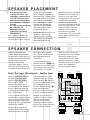
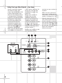
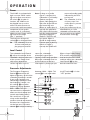
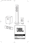
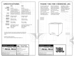
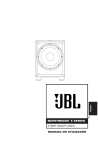
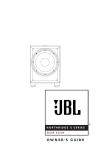
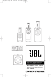
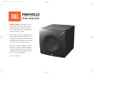
S P E C I F I C AT I O N S
Amplifier Power (RMS):
Driver:
Inputs:
Outputs:
Low-Pass Frequency:
High-Pass Frequency:
Frequency Response:
Dimensions (H x W x D):
Weight:
400 Watts
12" PolyPlas™ (polymer-coated cellulose fiber) cone;
rubber surround; SFG™; magnetic shorting rings;
high-temp, oversized, fiberglass voice coil; HeatScape™
motor structure; cast-aluminum basket
Line Level (switchable to LFE), BassQ™ and
Speaker Level with gold-plated, 5-way binding posts
BassQ and Speaker Level (High-Pass with
gold-plated, 5-way binding posts)
Continuously variable from 50Hz – 150Hz
150Hz when using speaker-level outputs
22Hz – Low-pass crossover setting
17-3/16" (with feet, without spikes) x 16-3/16" x 18" (19" with grille)
437mm (with feet, without spikes) x 411mm x 457mm (483mm with grille)
56 lb/25.5kg
All features and specifications are subject to change without notice.
* Trademarks of Dolby Laboratories.
DTS is a registered trademark of Digital Theater Systems, Inc.
OWNER’S GUIDE
PRODUCT LINE:
MODEL
NUMBER:
STUDIO™
PRO SOUND
COMES HOME™
SERIES
S120P II
JBL Consumer Products
250 Crossways Park Drive, Woodbury, NY 11797
8500 Balboa Boulevard, Northridge, CA 91329
800-336-4JBL (4525) (USA only)
D E S I G N G O A L : Bring the thrill of live performance and movie sound to
the home environment by calling on JBL’s professional engineering leadership.
www.jbl.com
W O O F E R T Y P E : Pure-cellulose fiber
JBL is a registered trademark of JBL, Incorporated.
P O R T D E S I G N : FreeFlow™ flared
Part No.: 338003-001
P R O F E S S I O N A L R E F E R E N C E : Studio Monitor
© 2001 JBL, Incorporated
THANK YOU FOR CHOOSING JBL
For more than 50 years, JBL
has been involved in every
aspect of music and film
recording and reproduction,
from live performances to the
recordings you play in your
home, car or office.
note of enjoyment that you
expected – and that when
you think about purchasing
additional audio equipment
for your home, car or
office, you will once again
choose JBL.
you posted on our latest
advancements, and helps us
to better understand our
customers and build products
that meet their needs and
expectations.
We’re confident that the JBL
loudspeakers you have
chosen will provide every
Please take a moment to
complete the enclosed profile
card. It enables us to keep
JBL Consumer Products
X +
0 +
Y2
0
M HZ
S120PII
X + 0 + Y 2 0 M HZ”
X + 0 + Y2
OWNER’S GUIDE
PRODUCT LINE:
STUDIO™ SERIES
D E S I G N G O A L : Bring the thrill of live performance and movie
sound to the home environment by calling on JBL’s professional
engineering leadership.
W O O F E R T Y P E : Pure-cellulose fiber
P O R T D E S I G N : FreeFlow™ flared
P R O F E S S I O N A L R E F E R E N C E : Studio Monitor
READ THIS!
CAUTION
RISK OF ELECTRIC SHOCK
DO NOT OPEN
CAUTION: To prevent electric shock,
do not use this (polarized)
plug with an extension cord,
receptacle or other outlet
unless the blades can
be fully inserted to
prevent blade exposure.
The lightning flash with arrowhead symbol,
within an equilateral triangle, is intended to
alert the user to the presence of uninsulated
“dangerous voltage” within the product’s
enclosure that may be of sufficient magnitude to constitute a
risk of electric shock to persons.
The exclamation point within an equilateral
triangle is intended to alert the user to the
presence of important operating and
maintenance (servicing) instructions in the
literature accompanying the appliance.
1. Read Instructions. All the safety and
operating instructions should be read before
the product is operated.
2. Retain Instructions. The safety and
operating instructions should be retained
for future reference.
3. Heed Warnings. All warnings on the
product and in the operating instructions
should be adhered to.
4. Follow Instructions. All operating and use
instructions should be followed.
5. Cleaning. Unplug this product from the
wall outlet before cleaning. Do not use
liquid cleaners or aerosol cleaners. Use a
damp cloth for cleaning.
6. Attachments. Do not use attachments not
recommended by the product manufacturer,
as they may cause hazards.
7. Water and Moisture. Do not use this
product near water – for example, near a
bathtub, wash bowl, kitchen sink or laundry
tub; in a wet basement; or near a swimming
pool; and the like.
8. Accessories. Do not place this product on
an unstable cart, stand, tripod, bracket, or
table. The product may fall, causing serious
injury to a child or adult, and serious
damage to the product. Use only with a cart,
stand, tripod, bracket, or table recommended
by the manufacturer, or sold with the
product. Any mounting of the product should
follow the manufacturer’s instructions, and
should use a mounting accessory
recommended by the manufacturer.
9. A Product and Cart Combination Should
Be Moved with Care. Quick stops, excessive
force, and uneven surfaces
may cause the product and
cart combination to overturn.
10. Ventilation. Slots and
openings in the cabinet are
provided for ventilation and to ensure
reliable operation of the product and to
protect it from overheating, and these
openings must not be blocked or covered.
The openings should never be blocked by
placing the product on a bed, sofa, rug, or
other similar surface. This product should
not be placed in a built-in installation such
as a bookcase or rack unless proper
ventilation is provided or the manufacturer’s
instructions have been adhered to.
2
Important Safety Precautions!
11. Power Sources. This product should be
operated only from the type of power source
indicated on the marking label. If you are
not sure of the type of power supply to your
home, consult your product dealer or local
power company. For products intended to
operate from battery power, or other
sources, refer to the operating instructions.
12. Polarization. This product may be
equipped with a polarized alternatingcurrent-line plug (a plug having one blade
wider than the other). This plug will fit into
the power outlet only one way. This is a
safety feature. If you are unable to insert the
plug fully into the outlet, try reversing the
plug. If the plug should still fail to fit, contact
your electrician to replace your obsolete
outlet. Do not defeat the safety purpose of
the polarized plug.
13. Power-Cord Protection. Power-supply
cords should be routed so that they are not
likely to be walked on or pinched by items
placed upon or against them, paying
particular attention to cords at plugs,
convenience receptacles, and the point
where they exit from the product.
14. Nonuse Periods. The power cord of the
product should be unplugged from the outlet
when left unused for long periods of time.
15. Outdoor Antenna Grounding. If an outside
antenna or cable system is connected to the
product, be sure the antenna or cable
system is grounded so as to provide some
protection against voltage surges and builtup static charges. Article 810 of the National
Electrical Code, ANSI/NFPA 70, provides
information with regard to proper grounding
of the mast and supporting structure,
grounding of the lead-in wire to an antenna
discharge unit, size of grounding conductors,
location of antenna-discharge unit,
connection to grounding electrodes, and
requirements for the grounding electrode.
See Figure A.
16. Lightning. For added protection for this
product during a lightning storm, or when
it is left unattended and unused for long
periods of time, unplug it from the wall outlet
and disconnect the antenna or cable system.
This will prevent damage to the product due
to lightning and power-line surges.
17. Power Lines. An outside antenna system
should not be located in the vicinity of
overhead power lines or other electric light
or power circuits, or where it can fall into
such power lines or circuits. When installing
an outside antenna system, extreme care
should be taken to keep from touching such
power lines or circuits, as contact with them
might be fatal.
18. Overloading. Do not overload wall
outlets, extension cords, or integral
convenience receptacles, as this can
result in a risk of fire or electric shock.
19. Object and Liquid Entry. Never push
objects of any kind into this product through
openings, as they may touch dangerous
voltage points or short-out parts that could
result in a fire or electric shock. Never spill
liquid of any kind on the product.
20. Servicing. Do not attempt to service this
product yourself, as opening or removing
covers may expose you to dangerous
voltage or other hazards. Refer all servicing
to qualified service personnel.
21. Damage Requiring Service. Unplug this
product from the wall outlet and refer servicing to qualified service personnel under
the following conditions:
a. The power-supply cord or the plug has
been damaged; or
b. Objects have fallen onto, or liquid has
been spilled into, the product; or
c. The product has been exposed to rain or
water; or
d. The product does not operate normally
when following the operating instructions.
Adjust only those controls that are covered
by the operating instructions, as an improper
adjustment of other controls may result in
damage and will often require extensive
work by a qualified technician to restore the
product to its normal operation; or
e. The product has been dropped or
damaged in any way; or
f. The product exhibits a distinct change
in performance – this indicates a need for
service.
22. Replacement Parts. When replacement
parts are required, be sure the service
technician has used replacement parts
specified by the manufacturer or that have
the same characteristics as the original part.
Unauthorized substitutions may result in fire,
electric shock or other hazards.
23. Safety Check. Upon completion of any
service or repairs to this product, ask the
service technician to perform safety checks
to determine that the product is in proper
operating condition.
24. Wall or Ceiling Mounting. The product
should be mounted to a wall or ceiling only
as recommended by the manufacturer.
25. Heat. The product should be situated
away from heat sources such as radiators,
heat registers, stoves, or other products
(including amplifiers) that produce heat.
Figure A.
Example of Antenna Grounding
as per National Electrical Code,
ANSI/NFPA 70
Antenna Lead-In Wire
Ground Clamp
Antenna Discharge Unit (NEC Section 810-20)
Grounding Conductors (NEC Section 810-21)
Electric Service Equipment
Ground Clamps
Power Service Grounding Electrode System
(NEC Art 250, Part H)
SPEAKER PLACEMENT
• As a general rule, bass
response increases as a
subwoofer is placed closer
to a wall. Therefore, bass
output is maximized when
the subwoofer is placed in
a corner.
• It is also recommended that
the subwoofer be
positioned along the
same wall as the front
loudspeakers.
Low-frequency sounds are
normally omnidirectional,
meaning the listener can’t tell
where they are generated
from. However, frequencies
between 75Hz – 150Hz can be
localized, especially at higher
volume levels. Positioning
your subwoofer as recommended will provide the
most natural soundstage
and imaging from your
loudspeaker system.
Remember that these are just
guidelines. Since every
listening room is different,
JBL strongly recommends
experimenting with the
positioning of your subwoofer
to obtain the most pleasing
results in your room. One
technique that can help you
find the ideal subwoofer
location is to temporarily
place the subwoofer near the
main listening location. Then
move around the room and
determine where you hear
the most pleasing bass
performance. This would then
be the ideal location for the
subwoofer.
SPEAKER CONNECTION
When we designed the
S120PII powered subwoofer,
our goal was to offer the user
the best possible performance
combined with the most
flexible and complete
installation options. Please
look over the following three
examples to determine which
description best matches
your system and follow the
corresponding hookup
instructions.
To use the binding-post
speaker terminals •ª with
bare wire, unscrew the collar
until the pass-through hole in
the center post is visible
under the collar. Insert the
bare end of the wire through
the hole in the post, then
screw the collar back down
until the connection is tight.
The holes in the center of the
collars are intended for
banana-type connectors.
Right Front
Left Front
Dolby* Pro Logic* (Non-Digital) – Speaker Level
Use this installation method
for Dolby Pro Logic applications (not Dolby Digital,
DTS® or other digital
processing), where the
receiver/processor does not
have a subwoofer output or
a volume-controlled preamp
(line-) level output:
and right terminals on the
subwoofer that are marked
“High Level In” •. Connect
the left and right terminals on
the subwoofer that are
marked “High Level Out” ª
to the corresponding
terminals on the back of your
front left and right speakers.
If your receiver features bass
management capabilities that
require you to configure your
speaker settings, make sure
to set your left- and right-front
speakers to “LARGE”.
Connect your receiver or
amplifier’s center, left and
right surround-speaker
terminals to the corresponding terminals on the
back of your center, left and
right surround speakers.
Connect your receiver or
amplifier’s front left and right
speaker terminals to the left
Center
+
–
+
+
–
–
Subwoofer
LL
•
HIGH
LEVEL
IN
+
RR
–
L
HIGH
LEVEL
OUT`
ª
R
Receiver
Left Front
+
–
Left Surround
+
–
Left Surround
+
–
Center
+
Right Front
–
+
–
Right Surround
+
–
Right Surround
+
–
3
Dolby Pro Logic (Non-Digital) – Line Level
Use this installation method
for Dolby Pro Logic applications (not Dolby Digital, DTS
or other digital processing),
where the receiver/processor
is equipped with a subwoofer
output or a volume-controlled
preamp (line-) level output:
Use RCA-type patch cords
to connect the line-level
subwoofer outputs on your
receiver or amplifier to the
Line Level inputs ¶ on the
subwoofer. IMPORTANT:
Make sure that the LFE toggle
switch ™ on the subwoofer is
in the “Normal” position. Do
not use the “LFE” position
with Dolby Pro Logic-only
processors.
Note: If your receiver or
amplifier only has one
subwoofer output jack,
then you may connect the
subwoofer output on your
receiver/preamplifier to either
the left or right Line Level
input ¶ on the subwoofer. It
makes no difference which
jack you choose.
terminals on your receiver or
amplifier.
Make sure your receiver or
processor is configured correctly: Make sure that the subwoofer is configured as “On.”
Note for advanced users: If
your receiver/processor has
a built-in low-pass crossover
filter for the subwoofer output,
then the LFE switch ™ should
be set to the “LFE” position to
bypass the subwoofer’s
internal crossover.
Connect each speaker to the
corresponding speaker
¡ ™ £
180°
LFE
ON
0°
NORMAL
OFF
PHASE
RECEIVER
¢
80Hz
Subwoofer
Out
L
AUTO
CROSSOVER
FREQUENCY
R
50Hz
BASSQ
(See owner’s
manual
before use)
∞
LEVEL
150Hz
IN
MIN
OUT
MAX
R
L
LINE
LEVEL IN
(For LFE
use R or L)
§
¶
L
HIGH
LEVEL
IN
•
HIGH
LEVEL
OUT
ª
R
+
–
L
R
4
Dolby Digital or DTS (or Other Digital Surround Mode) Connection
Use this installation method
for Dolby Digital, DTS or other
digital surround processors:
IMPORTANT: Make sure that
the LFE toggle switch ™ on
the subwoofer is in the “LFE”
position. Use the Line Level
input jacks ¶ for the LowFrequency Effects channel.
Connect these jacks to the
LFE output or subwoofer
output on your receiver or
amplifier.
Note: If your receiver or
amplifier has only one
subwoofer output jack,
then you may connect the
subwoofer output on your
receiver/preamplifier to either
the left or right Line Level
input ¶ on the subwoofer. It
makes no difference which
jack you choose.
Connect each speaker to the
corresponding speaker
terminals on your receiver or
amplifier.
Make sure that you have
configured your surround
sound processor for
“Subwoofer On” or “LFE On.”
The front left, front right,
center and rear speakers
should be set to “Small” or
“Large” depending on their
size and frequency response.
Consult your receiver’s or
processor’s owner’s manual.
¡ ™ £
180°
LFE
ON
0°
NORMAL
OFF
PHASE
AUTO
¢
80Hz
RECEIVER/PREAMPLIFIER
CROSSOVER
FREQUENCY
Subwoofer
Output/LFE
50Hz
BASSQ
(See owner’s
manual
before use)
∞
LEVEL
150Hz
IN
MIN
OUT
MAX
§
R
L
LINE
LEVEL IN
(For LFE
use R or L)
¶
L
HIGH
LEVEL
IN
•
HIGH
LEVEL
OUT
ª
R
+
–
L
R
BassQ™ Jacks
The jacks marked “BassQ” §
are for use with the JBL
BassQ bass equalization
module that will be released
in the near future. The BassQ
will enable you to optimize
your system’s bass response
by equalizing the output of
multiple subwoofers to
best match your listening
environment. DO NOT connect these jacks to any other
device. Do not use the BassQ
jacks § without having first
read the BassQ owner’s
manual.
5
O P E R AT I O N
Power
The S120PII is equipped with
both a master Power switch
‚ and an Auto turn-on/turnoff switch £. In order to
function, the S120PII must
be plugged into an active
electrical outlet (but not an
accessories outlet on another
component of your audio
system such as a receiver),
and the master Power switch
‚ must be turned on
(the “•” position).
The Auto turn-on/turn-off
switch £ has three positions:
On The subwoofer is on at
all times and ready to
play program material.
Auto As long as no audio
signal is received, the
subwoofer is in Standby
mode to conserve
power, indicated by the
red color of the LEDs on
the front of the unit.
When an audio signal is
sensed, the subwoofer
will switch itself into the
fully On mode and begin
playing the program
material. The LEDs will
turn green. When a
period of about twenty
minutes goes by during
which no signal is
sensed, the S120PII will
return to Standby mode,
indicated by the LEDs
turning red.
Off The subwoofer is off at
all times, even if an
audio signal is present
at its inputs.
If you plan to be away for an
extended time, or if the
subwoofer will not be used,
you may wish to turn off the
master Power switch ‚.
room size, subwoofer
placement, type of main
speakers and listener position.
Adjust the subwoofer level so
that the volume of the bass
information is pleasing to you.
When using a Dolby Digital/
DTS receiver, adjust the LFE
level on the receiver to 0dB,
and then adjust the subwoofer
Level Control ∞ for the
desired amount of bass.
between 120Hz – 150Hz. This
control ¢ is not used when
the LFE switch ™ is in the
“LFE” position.
Level Control
The subwoofer Level Control
∞ adjusts the volume of the
subwoofer relative to the rest
of the system. Proper level
adjustment depends on
several variables such as
Crossover Adjustments
The Crossover Frequency
Control ¢ determines the
highest frequency at which the
subwoofer reproduces sounds.
If your main speakers can
comfortably reproduce some
low-frequency sounds, set
this control ¢ to a lower
frequency setting, between
50Hz – 100Hz. This will
concentrate the subwoofer’s
efforts on the ultradeep bass
sounds required by today’s
films and music. If you are
using smaller bookshelf
speakers that do not extend to
the lower bass frequencies,
set the low-pass Crossover
control ¢ to a higher setting,
6
¡ ™ £
180°
LFE
ON
0°
NORMAL
OFF
PHASE
AUTO
80Hz
¢
CROSSOVER
FREQUENCY
§
¶
LEVEL
50Hz
∞
BASSQ
(See owner’s
manual
before use)
150Hz
IN
MIN
OUT
MAX
R
L
L
S120PII
CAUTION
RISK OF ELECTRIC SHOCK
DO NOT OPEN
WARNING: TO REDUCE THE RISK OF FIRE OR ELECTRIC SHOCK,
DO NOT EXPOSE THIS APPLIANCE TO RAIN OR MOISTURE.
HIGH
LEVEL
IN
•
LINE
LEVEL IN
(For LFE
use R or L)
AVERTISSEMENT: POUR PRÉVENIR LES RISQUES D’INCENDIE OU
DE CHOC ÉLECTRIQUE ÉVITER D’EXPOSER CET APPAREIL A LA
PLUIE OU A L’HUMIDITÉ.
R
+
–
ON
L
ª
HIGH
LEVEL
OUT
R
‚
OFF
Phase Control
subwoofer placement and
listener position. Adjust the
Phase switch ¡ to maximize
bass output at the listening
position.
The Phase Control ¡
determines whether the
subwoofer’s piston-like action
moves in and out in phase
with the main speakers or
opposite the main speakers.
There is no correct or
incorrect setting. Proper
phase adjustment depends on
several variables such as
Remember, every system,
room and listener is different.
There are no right or wrong
settings; this switch ¡ offers
the added flexibility to adjust
your subwoofer for optimum
performance for your specific
listening conditions without
having to move your speakers.
If at some time in the future
you happen to rearrange your
listening room and move
your speakers, you should
experiment with the Phase
switch ¡ in both positions,
and leave it in the position
that maximizes bass
performance.
TROUBLESHOOTING
If you used the High Level
(speaker) inputs • and there
is no sound from any of the
speakers:
• Check that receiver/amplifier
is on and a source is playing.
• Check that powered
subwoofer is plugged into
an active electrical outlet
and is switched on £‚.
• Check all wires and
connections between
receiver/amplifier and
speakers. Make sure all wires
are connected. Make sure
none of the speaker wires
are frayed, cut or punctured.
Make sure no wires are
touching other wires or
terminals and creating a
short circuit.
• Review proper operation
of your receiver/amplifier.
If there is low (or no) bass
output:
• Make sure the connections
to the left and right “Speaker
Inputs” • have the correct
polarity (+ and –).
• Make sure that the
subwoofer is plugged into an
active electrical outlet and
that both power switches
are on £‚.
• Adjust the Crossover point
¢.
• Flip the Phase Control
switch ¡ to the opposite
position.
• If you are using a Dolby
Digital/DTS receiver or
processor, make sure that the
subwoofer adjustments on
the receiver/processor are
set up correctly. When using
the S120PII’s Speaker Level
inputs •, you should set your
receiver to configure the
main left and right speakers
as “LARGE”.
• Slowly turn the Level
Control ∞ clockwise until
you begin to hear the desired
amount of bass.
If you used the Line Level
inputs ¶ and there is no
sound from the subwoofer:
• Check that receiver/amplifier
is on and a source is playing.
• Check that powered
subwoofer is plugged into an
active electrical outlet and
that both Power switches
are on £‚.
• Check all wires and connections between receiver/
amplifier and subwoofer.
Make sure all wires are
connected. Make sure none
of the wires are frayed, cut
or punctured.
• Review proper operation of
your receiver/amplifier.
• Slowly turn the Level
Control ∞ clockwise until
you begin to hear the desired
amount of bass.
• Make sure that you have
configured your receiver/
processor so that the
subwoofer/LFE output is on.
7