1
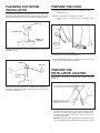
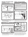
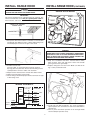
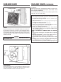
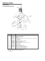
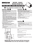
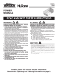
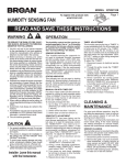
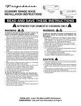
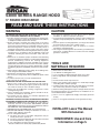
53000 SERIES RANGE HOOD
5” ROUND DISCHARGE
READ AND SAVE THESE INSTRUCTIONS
WARNING
CAUTION
TO REDUCE THE RISK OF FIRE, ELECTRIC SHOCK, OR INJURY TO PERSONS, OBSERVE THE FOLLOWING:
1. Use this unit only in the manner intended by the manufacturer.
If you have questions, contact the manufacturer at the address
or telephone number listed in the warranty.
2. Before servicing or cleaning unit, switch power off at service
panel and lock the service disconnecting means to prevent
power from being switched on accidentally. When the service
disconnecting means cannot be locked, securely fasten a
prominent warning device, such as a tag, to the service panel.
3. Installation work and electrical wiring must be done by a qualified person(s) in accordance with all applicable codes and
standards, including fire-rated construction codes and standards.
4. Sufficient air is needed for proper combustion and exhausting
of gases through the flue (chimney) of fuel burning equipment to
prevent backdrafting. Follow the heating equipment
manufacturer’s guideline and safety standards such as those
published by the National Fire Protection Association (NFPA),
and the American Society for Heating, Refrigeration and Air
Conditioning Engineers (ASHRAE), and the local code authorities.
5. When cutting or drilling into wall or ceiling, do not damage electrical wiring and other hidden utilities.
6. Ducted fans must always be vented to the outdoors.
7. Do not use this range hood with an additional speed control
device.
8. To reduce the risk of fire, use only metal ductwork.
9. This unit must be grounded.
TO REDUCE THE RISK OF A RANGE TOP GREASE FIRE:
1. Never leave surface units unattended at high settings.
Boilovers cause smoking and greasy spillovers that may ignite. Heat oils slowly on low or medium settings.
2. Always turn hood ON when cooking at high heat or when
cooking flaming foods.
3. Clean ventilating fans frequently. Grease should not be allowed to accumulate on fan or filter.
4. Use proper pan size. Always use cookware appropriate for
the size of the surface element.
TO REDUCE THE RISK OF INJURY TO PERSONS IN THE EVENT
OF A RANGE TOP GREASE FIRE, OBSERVE THE FOLLOWING:*
1. SMOTHER FLAMES with a close-fitting lid, cookie sheet, or
metal tray, then turn off the burner. BE CAREFUL TO PREVENT BURNS. If the flames do not go out immediately, EVACUATE AND CALL THE FIRE DEPARTMENT.
2. NEVER PICK UP A FLAMING PAN - You may be burned.
3. DO NOT USE WATER, including wet dishcloths or towels - a
violent steam explosion will result.
4. Use an extinguisher ONLY if:
A. You know you have a Class ABC extinguisher and you
already know how to operate it.
B. The fire is small and contained in the area where it started.
C. The fire department is being called.
D. You can fight the fire with your back to an exit.
* Based on “Kitchen Fire Safety Tips” published by NFPA.
1. For general ventilating use only. Do not use to exhaust
hazardous or explosive materials and vapors.
2. To avoid motor bearing damage and noisy and/or unbalanced
impellers, keep drywall spray, construction dust, etc. off power
unit.
3. For best capture of cooking impurities, your range hood should
be mounted 18-24" above the cooking surface.
4. Please read specification label on product for further
information and requirements.
5. This range hood is designed for use with two (2) wall-mounted,
general-use, 15-Amp switches for control of the fan and light
(purchase separately).
TOOLS AND
MATERIALS REQUIRED
❏
❏
❏
❏
❏
❏
❏
Drill, electric or ratchet drive
1/8" Drill bit for drilling pilot holes
1-1/4" wood bit for drilling electrical wiring access hole
One straight blade and one phillips head screwdriver
Pliers
Pencil and ruler and/or tape measure
Saber saw or keyhole saw for cutting 1" x 2" wood strips to length
and cutting wall or cabinet openings
❏ Caulking, metal snips, duct tape, duct (with elbows and transition, if necessary) and roof or wall cap, as required
❏ Electrical wiring and supplies of type to comply with local codes
The following materials are required only for installations on recessed bottom kitchen cabinets:r Ducted
❏ Two 1" x 2" x 12" (approximate length) wood strips (purchase
locally)
❏ Four 1-1/4" long flat head wood screws (purchase locally)
INSTALLER: Leave This Manual
With Homeowner.
HOMEOWNER: Use and Care
Information on Page 5.
1
PLANNING DUCTWORK
INSTALLATION
PREPARE THE HOOD
1. Unpack hood and check contents. You should receive:
1 -Aluminum Filter
Begin planning ductwork by deciding where the duct will run between the range hood and the outside. For best performance, use
the shortest possible duct run and a minimum number of elbows.
2. Remove wiring box cover. Under cover find:
1 -Plastic Bag containing loose mounting hardware
ROOF CAP
5" ROUND DUCT
MODEL P85
DAMPER
Straight up through the roof using 5" round duct (for single story
installations only).
3. Remove top or rear electrical knockout.
4. Install Model P85 damper over opening in top of hood. Use
three (3) screws provided with damper.
ADJUSTABLE
ELBOW
WALL CAP
PREPARE THE
INSTALLATION LOCATION
5" ROUND
DUCT
Omit STEP 1 if hood will be installed under cabinets with flush
bottom.
Ducting between the ceiling joists (for multi-story installations) or
through the soffit space above the cabinets (where the soffit connects to an outside wall).
1. (For installation on recessed bottom cabinets only) Attach a
wood filler strip at each side of recessed area under cabinet.
Use two 1" x 2" strips cut to length. If recess is deeper than 1"
use thicker strips. Attach strips with 1-1/4" wood screws, 3"
from each end of strip.
Optional: Attach wood filler strips under front and back of cabinet and use additional 3/16” diameter mounting holes in hood.
2
PREPARE THE INSTALLATION
LOCATION (CONTINUED)
NOTE
These instructions will follow plans made on Page 2. Start
at the exterior and run ductwork back to the range hood.
For best possible performance, use the shortest possible
duct run and a minimum number of elbows. Do not vent a
range hood into an attic space. A buildup of grease in the
attic could become a fire hazard.
Use only metal ductwork. DO NOT USE PLASTIC DUCT.
Assemble duct run securely so that in case of a grease fire
on the range, the fire will be contained inside metal
ductwork.
Use duct tape to make all duct connections secure and air
tight.
▼
1½”
INSTALL THE DUCTWORK
10½”
7½”
6¼”
97/8”
FILLER
STRIP
▼
¾”
12”
7½”
1. Follow appropriate directions below for type of duct run you
install.
CENTER LINE
HOOD WIDTH
WALL CAP
SOFFIT
Additional 3/16”
diameter mounting
holes
▲
3
▲
;;;;;;;;;
;;;;;;;;;
;;
;;
;;
;;
;;
;;
;;
;;
;;
;;
;;;;;;;;;;;
;;;;;;;;;
;;
;;
;;
;;
;;
;;
;;
;;
;;
;;
;;
;;
;;
;;
;;
;;
;;
CABINET
;;
▲
▲
4
3
▲
▲
5”
diameter
5
2
4
WALL
CAP
Wall Cap Discharge: Use saber saw or keyhole saw to cut hole
slightly larger than duct size used so that duct will line up easily
with damper/duct conector on hood. Install casing strips if cap will
be installed on siding. Attach required amount of duct to wall cap
and run duct back to hood. Fasten cap to wall and caulk well.
2. Measure and mark the following:
a.) Electrical wiring opening in wall or cabinet.
b.) Duct opening in wall or cabinet.
WARNING
WHEN CUTTING OR DRILLING INTO WALL OR CABINET, BE
CAREFUL NOT TO CUT EXISTING ELECTRICAL WIRING.
ROOF CAP
3. Use 1-1/4" bit to drill opening for electric wiring.
4. Cut out duct opening in cabinet with saber saw or keyhole
saw.
¾"
DUCT
KEYHOLE SLOT OUTLINE
SOFFIT
FILLER STRIPS
CABINET
Roof Cap Discharge: Cut a hole in roof slightly larger than duct
size being used. Run ductwork down to hood location. Leave 3/4"
of duct projecting above roof surface on high side. Trim duct parallel to roof pitch and seal all around duct with roof cement.
Carefully trim shingles and slide back of roof sheet under shingles.
Nail roof sheet to roof under shingles at top two corners and two
sides. Nail sheet directly to roof in four places at bottom.
Using roof cement, seal all nail heads and shingles which were
cut or lifted. Do not seal bottom edge of roof sheet.
CENTER
LINE
5. Center hood in installation opening and trace keyhole slots onto
wood filler strips on cabinet bottom.
6. Screw four #10 x 7/8 wood screws into exact center of narrow
end of traced keyhole slots. Allow 3/8" of screws to project, so
that hood can be fitted into place later.
3
INSTALL RANGE HOOD
INSTALL RANGE HOOD (CONTINUED)
WARNING
TURN OFF THE PROPER CIRCUIT AT THE SERVICE ENTRANCE BEFORE WIRING THIS RANGE HOOD.
RANGE HOOD WIRING
IMPORTANT:
This hood is designed to be controlled using (2) separate, general-use wall switches. Use 3-wire plus ground power cable between switches and hood.
WHITE
TO
WHITE
BLACK
TO
BLACK
3-WIRE PLUS GROUND
POWER CABLE
GROUND (Bare
or green wire)
CONNECTOR
RED
TO
RED
1. Run power cable from location of switches to hood location
and through hole drilled in wall or cabinet. Split wiring for 6"
and install proper connector for type of wire used.
WARNING
ALL ELECTRICAL CONNECTIONS MUST BE IN ACCORDANCE WITH LOCAL CODES, ORDINANCES, OR NATIONAL
ELECTRICAL CODE. IF YOU ARE UNFAMILIAR WITH METHODS OF INSTALLING ELECTRICAL WIRING, SECURE THE
SERVICES OF A QUALIFIED ELECTRICIAN.
6. Strip 1/2" of insulation from wires. Connect white to white,
black to black, red to red and green or bare wire beneath
green ground screw (provided).
7. Replace wiring box cover and screw. Make sure that all wiring is safely contained inside.
2. Position hood so that:
a.)Power cable is routed through knockout opening
b.)Large part of keyhole slots fit over hood mounting screws.
c.) Damper/duct connector slides into ductwork.
3. Adjust hood so that hood front is flush with cabinet frame.
4. Tighten hood mounting screws firmly.
5. Fasten wiring to hood with proper electrical connector for type
of wire being used.
LIGHT LENS
SOCKET
WIRING SCHEMATIC
LIGHT
SWITCH
BLACK
120 VAC
LINE IN
WHITE
FAN
SWITCH
3-wire plus ground
power cable
RANGE HOOD
BLACK
BLACK
RED
RED
WHITE
LIGHT
FAN
WHITE
WHITE
GROUND
8. Install light (75 Watt maximum). For easier installation,
squeeze plastic lens and remove it from hood. Remember to
reinstall lens.
9. Turn on power and check operation of fan and light. Make
sure that damper operates freely.
GROUND
4
USE AND CARE
USE AND CARE (CONTINUED)
CLEANING
Clean your hood with a mild detergent suitable for painted surfaces. DO NOT USE ABRASIVE CLOTH, STEEL WOOL PADS
OR SCOURING POWDERS.
Fan assembly may be vacuumed. Fan assembly is permanently
lubricated, and never needs oiling.
FILTER RETAINER
FILTER
HOW TO AVOID A COMMON RANGE-TOP GREASE FIRE
• Your range hood provides a protective barrier between the
cooking surface and the cabinets.
• Keep fan, filters and grease laden surfaces CLEAN according to instructions.
• Always turn hood ON when cooking at high heat to keep the
cooking area and the hood cooler.
• Use high heat settings only when necessary.
• Never leave cooking surface unattended. Boil-over causes
smoking and greasy spillovers that may ignite.
• Always use adequate-sized utensils.
• If preparing flaming foods, such as Cherries Jubilee, always
turn hood ON to HIGH to prevent a high heat situation which
can cause damage or fire.
HOW TO EXTINGUISH A COMMON RANGE-TOP GREASE
FIRE
• Never pick up a flaming pan. If dropped, flames can spread
quickly.
• DO NOT USE WATER! A violent steam explosion may result. Wet dishcloths or towels are also dangerous.
• Smother flames with a close fitting lid, cookie sheet or metal
tray.
• Flaming grease can also be extinguished with baking soda
or a multi-purpose dry chemical extinguisher.
• Turn off surface units - if you can do so without getting burned.
TABS
FILTER
Remove aluminum filter by turning filter retainer to one side. Filter should be washed once a month in a hot detergent solution.
Aluminum filters are dishwasher safe. When installing filter, make
sure that filter slides under retaining tabs on back of fan housing.
Turn filter retainer so that arrows on retainer point toward front
and back of hood.
WARNING
ALWAYS DISCONNECT ELECTRIC POWER BEFORE SERVICING RANGE HOOD.
SCREWS
FAN ASSEMBLY
Remove filter. Remove two screws holding motor bracket to range
hood, and unplug fan assembly. Be careful not to allow fan assembly to drop when screws are removed. (FIG. 14)
5
SERVICE PARTS
53000 SERIES
12
5" ROUND DUCTED HOOD
16
14
15
KEY NO.
PART NO.
DESCRIPTION
1
2
3
4
5
98006621
99170245
99271248
99110437
97011217
6
7
8
9
10
11
12
13
14
15
**
99020248
99260428
98005568
97014665
97006931
99420472
97014729
97015347
99150471
99150470
----
Outlet Box Cover
#8 x 3/8 Sheet Metal Screw*
Bulb Holder with Wires
Light Lens
Screw/Nut Kit (Includes 2 - #10-16 x .500 screws and 2 - #10-16 sheet
metal nuts)
Fan Blade
#6-32 Locking Nuts* (2 Required)
Motor Mounting Bracket
Motor Assembly (Includes Key Nos. 6, 7, & 8)
Aluminum Filter
Filter Retainer
Damper Assembly
Motor Receptacle with Wires
#10-32 x 1/2 Green Ground Screw*
#8 x 3/8 Sheet Metal Screw, AB Point*
Light Bulb, 75 Watt (not included)*
Order service parts by "PART NO." - NOT by "KEY NO."
* Standard Hardware. May be purchased locally.
** Not Illustrated.
6
WARRANTY
BROAN ONE YEAR LIMITED WARRANTY
Broan warrants to the original consumer purchaser of its products that such products will be free from defects in materials or
workmanship for a period of one year from the date of original purchase. THERE ARE NO OTHER WARRANTIES, EXPRESS OR
IMPLIED, INCLUDING, BUT NOT LIMITED TO, IMPLIED WARRANTIES OF MERCHANTABILITY OR FITNESS FOR A
PARTICULAR PURPOSE.
During this one-year period, Broan will, at its option, repair or replace, without charge, any product or part which is found to be
defective under normal use and service.
THIS WARRANTY DOES NOT EXTEND TO FLUORESCENT LAMP STARTERS AND TUBES. This warranty does not cover (a)
normal maintenance and service or (b) any products or parts which have been subject to misuse, negligence, accident, improper
maintenance or repair (other than by Broan), faulty installation or installation contrary to recommended installation instructions.
The duration of any implied warranty is limited to the one-year period as specified for the express warranty. Some states do not
allow limitation on how long an implied warranty lasts, so the above limitation may not apply to you.
BROAN’S OBLIGATION TO REPAIR OR REPLACE, AT BROAN’S OPTION, SHALL BE THE PURCHASER’S SOLE AND
EXCLUSIVE REMEDY UNDER THIS WARRANTY. BROAN SHALL NOT BE LIABLE FOR INCIDENTAL, CONSEQUENTIAL OR
SPECIAL DAMAGES ARISING OUT OF OR IN CONNECTION WITH PRODUCT USE OR PERFORMANCE. Some states do not
allow the exclusion or limitation of incidental or consequential damages, so the above limitation or exclusion may not apply to you.
This warranty gives you specific legal rights, and you may also have other rights, which vary from state to state. This warranty
supersedes all prior warranties.
To qualify for warranty service, you must (a) notify Broan at the address stated below or telephone: 1-800-637-1453, (b) give the
model number and part identification and (c) describe the nature of any defect in the product or part. At the time of requesting
warranty service, you must present evidence of the original purchase date.
Broan-NuTone LLC, 926 West State Street, Hartford, WI 53027 (1-800-637-1453)
7
99043003B