1
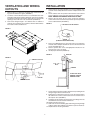
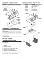
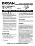
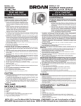
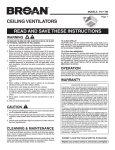
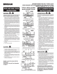
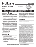
MODEL
PM44
POWER
MODULE
READ AND SAVE THESE INSTRUCTIONS
WARNING
WARNING
TO REDUCE THE RISK OF FIRE, ELECTRIC SHOCK, OR INJURY
TO PERSONS, OBSERVE THE FOLLOWING:
1. Use this unit only in the manner intended by the manufacturer. If
you have questions, contact the manufacturer at the address or
telephone number listed in the warranty.
2. Before servicing or cleaning unit, switch power off at service panel
and lock the service disconnecting means to prevent power from
being switched on accidentally. When the service disconnecting
means cannot be locked, securely fasten a prominent warning
device, such as a tag, to the service panel.
3. Installation work and electrical wiring must be done by a qualified
person(s) in accordance with all applicable codes and standards,
including fire-rated construction codes and standards.
4. Sufficient air is needed for proper combustion and exhausting of
gases through the flue (chimney) of fuel burning equipment to prevent backdrafting. Follow the heating equipment manufacturer’s
guideline and safety standards such as those published by the
National Fire Protection Association (NFPA), and the American
Society of Heating, Refrigeration and Air Conditioning Engineers
(ASHRAE), and the local code authorities.
5. When cutting or drilling into wall or ceiling, do not damage electrical wiring and other hidden utilities.
6. To reduce the risk of fire or electric shock, do not use this range
hood with an additional speed control device.
7. Ducted fans must always be vented to the outdoors.
8. To reduce the risk of fire, use only metal ductwork.
9. This unit must be grounded.
TO REDUCE THE RISK OF A RANGE TOP GREASE FIRE:
1. Never leave surface units unattended at high settings. Boilovers
cause smoking and greasy spillovers that may ignite. Heat oils
slowly on low or medium settings.
2. Always turn hood ON when cooking at high heat or when cooking
flaming foods.
3. Clean ventilating fans frequently. Grease should not be allowed to
accumulate on fan or filter.
4. Use proper pan size. Always use cookware appropriate for the
size of the surface element.
TO REDUCE THE RISK OF INJURY TO PERSONS IN THE EVENT
OF A RANGE TOP GREASE FIRE, OBSERVE THE FOLLOWING:*
1. SMOTHER FLAMES with a close-fitting lid, cookie sheet, or metal
tray, then turn off the burner. BE CAREFUL TO PREVENT BURNS.
If the flames do not go out immediately, EVACUATE AND CALL
THE FIRE DEPARTMENT.
2. NEVER PICK UP A FLAMING PAN — You may be burned.
3. DO NOT USE WATER, including wet dishcloths or towels - violent
steam explosion will result.
4. Use an extinguisher ONLY if:
A. You know you have a Class ABC extinguisher and you already know how to operate it.
B. The fire is small and contained in the area where it started.
C. The fire department is being called.
D. You can fight the fire with your back to an exit.
* Based on “Kitchen Fire Safety Tips” published by NFPA.
CAUTION
!
1. For general ventilating use only. Do not use to exhaust hazardous or explosive materials and vapors.
2. To avoid motor bearing damage and noisy and/or unbalanced
impellers, keep drywall spray, construction dust, etc. off power
unit.
3. For best capture of cooking impurities, your range hood should
be mounted so that the top of the hood is 24-30” above the cooking surface.
4. Please read specification label on product for further information and requirements.
Installer: Leave this manual with the homeowner.
Homeowner: Operating and Cleaning information on page 3.
VENTILATING AND WIRING
CUTOUTS
INSTALLATION
1. Remove blower housing and filters for easier installation. See
exhaust unit assembly illustration used for “Replacement Parts
List.”
2. Lift the exhaust unit into position and mark the hole locations
on the cabinet for each of the four keyhole mounting slots.
NOTE: REMOVE FASTENERS FROM PLASTIC BAG.
3. Remove the unit. Start all four screws (#10 x 5/8 slotted) in
center of the narrow neck of the keyhole slots previously marked
on the cabinet bottom (FIGURE 3).
1. Mark locations on cabinet for ventilating duct and electrical wiring from the dimensions given (FIGURE 1).
2. Cut holes at the marked locations to accommodate the ventilating duct and electrical wiring. Allow 3/4” extra on the ventilating opening toward the front of the cabinet. Be sure to minimize
openings, these will have to be sealed later (FIGURE 2).
3. Run house wiring through 1-1/2” diameter hole in cabinet or
wall. Be sure all wiring is in accordance with the National Electrical Code and local ordinances.
FIGURE 3
KEYHOLE SLOT IN CANOPY
FIGURE 1
SCREW
(IN INSTALLATION PARTS BAG)
4. There are predrilled holes on each side of the 3-1/2 x 10 hole in
exhaust unit for damper attachment. Use the small sheet metal
screws included (#8 x 1/4).
5. Remove junction box cover and appropriate knockout in exhaust unit for access to wiring.
6. Install proper ductwork (FIGURE 4).
RAIN CAP
FIGURE 4
FIGURE 2
CABINET CUTOUTS
3-1/4” x 10”
DUCT
DAMPER
IF RAIN CAP HAS A
DAMPER, REMOVE
DAMPER BLADE
STARTER HOLES
7. Lift the exhaust unit into position simultaneously feeding house
wiring through exhaust unit knockout.
8. Tighten the four mounting screws to secure the exhaust unit to
the cabinet. Be sure the screw heads are in the narrow neck of
the keyhole slots (FIGURE 3).
9. Complete electrical wiring in junction box according to the National Electrical Code and local ordinances.
10. Replace junction box cover.
11. Seal holes around ventilating pipe and wiring passing through
ceiling or walls with caulking or insulation to prevent heat loss.
12. Replace blower housing and filters.
2
BLOWER ORIENTATION
REPLACEMENT PARTS LIST
IMPORTANT: Be sure the blower is correctly orientated. Note arrow on the side of the blower housing indicating the correct air flow
direction (FIGURE 5).
Part No.
R561107
R567073
R730079
R610038
R566066
R520098
R531041
R531042
FIGURE 5 – VERTICAL DISCHARGE
VERTICAL
DISCHARGE
VENT
(TOP OF HOOD)
MOTOR
CONTROL
BLOWER
DISCHARGE –
LOCATE AT
DISCHARGE
VENT IN TOP
OF HOOD
Description
3-Pos. Rotary Light Switch
Motor, Speed Control
Blower Assembly
Filter
Lampholder
Motor
Blower Wheel CW
Blower Wheel CCW
LIGHT SWITCH
JUNCTION
BOX
THIS
SURFACE
TO REAR
BLOWER
ASSEMBLY
CLEANING INFORMATION
FILTER
For greatest efficiency, the aluminum filters should be removed and
cleaned periodically.
To clean, the filter should be soaked in hot water and detergent
then thoroughly rinsed. The aluminum filter can be cleaned in a
dishwasher.
THUMB
SCREW
BLOWER
COVER
EXTERIOR SURFACE
To preserve its lasting beauty, clean with a mild detergent. DO NOT
use abrasive cleaners.
MOTOR SPEED
TROUBLESHOOTING
FILTER
If you have a motor speed problem, please check the following list
for possible troubles.
1. Knockouts not removed from hood.
2. Blower assembly installed wrong – intended for vertical discharge but installed for horizontal discharge and vice versa
(FIGURE 5).
3. Damper blade not opening.
4. Duct undersized – reduced airflow because duct too small or
too long.
5. Restriction in duct from foreign materials or debris.
6. Undersized or restrictive wall or roof cap.
7. Damper blade in wall or roof cap not opening.
8. Wait for 20 - 30 seconds between speed changes for RPM to
adjust.
By removing or correcting these adverse factors, the motor speed
control will be able to decrease from maximum RPM.
3
WARRANTY
BROAN-NUTONE ONE YEAR LIMITED WARRANTY
Broan-NuTone warrants to the original consumer purchaser of its products that such
products will be free from defects in materials or workmanship for a period of one year
from the date of original purchase. THERE ARE NO OTHER WARRANTIES,
EXPRESS OR IMPLIED, INCLUDING, BUT NOT LIMITED TO, IMPLIED WARRANTIES OF MERCHANTABILITY OR FITNESS FOR A PARTICULAR PURPOSE.
During this one-year period, Broan-NuTone will, at its option, repair or replace,
without charge, any product or part which is found to be defective under normal use
and service.
THIS WARRANTY DOES NOT EXTEND TO FLUORESCENT LAMP STARTERS
AND TUBES. This warranty does not cover (a) normal maintenance and service or
(b) any products or parts which have been subject to misuse, negligence, accident,
improper maintenance or repair (other than by Broan-NuTone), faulty installation or
installation contrary to recommended installation instructions.
The duration of any implied warranty is limited to the one-year period as specified for
the express warranty. Some states do not allow limitation on how long an implied
warranty lasts, so the above limitation may not apply to you.
BROAN-NUTONE’S OBLIGATION TO REPAIR OR REPLACE, AT BROANNUTONE’S OPTION, SHALL BE THE PURCHASER’S SOLE AND EXCLUSIVE
REMEDY UNDER THIS WARRANTY. BROAN-NUTONE SHALL NOT BE LIABLE
FOR INCIDENTAL, CONSEQUENTIAL OR SPECIAL DAMAGES ARISING OUT
OF OR IN CONNECTION WITH PRODUCT USE OR PERFORMANCE. Some
states do not allow the exclusion or limitation of incidental or consequential damages,
so the above limitation or exclusion may not apply to you.
This warranty gives you specific legal rights, and you may also have other rights,
which vary from state to state. This warranty supersedes all prior warranties.
To qualify for warranty service, you must (a) notify Broan-NuTone at the address or
phone number below, (b) give the model number and part identification and (c)
describe the nature of any defect in the product or part. At the time of requesting
warranty service, you must present evidence of the original purchase date.
In the United States, contact:
Broan-NuTone LLC,
926 West State Street
Hartford, WI 53027
(1-800-637-1453)
NuTone, Inc.
4820 Red Bank Road
Cincinnati, Ohio 45227
(1-800-543-8687)
In Canada, contact:
Broan-NuTone Canada, Inc.
1140 Tristar Drive
Mississauga, Ontario, L5T 1H9
(1-888-882-7626)
626844B