1
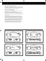
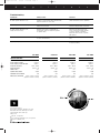
LC-Amplifier OM
A
3/4/99
10:55 AM
m
Page 2
p
l
i
f
i
e
r
s
LC-Amplifier OM
3/4/99
10:55 AM
Thank you
for purchasing a
JBL Loud + Clear amplifier. In
order that we may better serve you
should you require warranty service on your new amplifier, please
retain your original purchase
receipt and return the enclosed
warranty registration card.
Important: Installation of automotive stereo components can
require extensive experience in
performing a variety of mechanical and electrical procedures.
Although these instructions
explain, in a general sense, how
to install Loud + Clear amplifiers,
they may not show the exact
installation methods for your
particular vehicle. If you feel
you lack the tools or necessary
experience, ask your authorized
JBL car-audio dealer about professional installation options.
Page 3
Installation Warnings and Tips
• Always wear protective
eyewear when using tools.
• Turn off all audio systems and
other electrical devices before
you start.
• Disconnect the negative (–) lead
from your vehicle’s battery.
• Check clearances on both sides
of a planned mounting surface
before drilling any holes or
installing any screws. Remember
that the screws can extend behind
the surface.
• At the installation sites, locate
and make a note of all fuel lines,
hydraulic brake lines, vacuum
lines and electrical wiring. Use
extreme caution when cutting or
drilling in and around these areas.
• Before drilling or cutting holes,
use a utility knife to remove
unwanted fabric or vinyl to keep
material from snagging in a
drill bit.
Choosing a Location and Mounting the Amplifier
Amplifiers need air to stay cool. Suitable locations are under seats
(provided the amplifier doesn’t interfere with the seat-adjustment
mechanism), in the trunk or in any location that provides enough air
for the amp to cool itself. Do not mount the amplifier with the heat-sink
fins facing downward; this makes convection cooling of the amplifier
impossible.
Mount the amplifier so that it is not damaged by the feet of back-seat
passengers or shifting cargo in the trunk. Mount the amplifier so that it
remains dry – never mount an amplifier outside the car or in the engine
compartment.
Using the amplifier as a template, mark the location of the mounting holes
on the mounting surface, drill pilot holes and attach the amplifier to the
mounting surface with screws. Make sure the amplifier is mounted securely.
• When routing cables, keep inputsignal cables away from power
cables and speaker wires.
• When making connections,
ensure that they are secure and
properly insulated.
• If the amplifier’s fuse must be
replaced, use only the same type
and rating as that of the original.
Do not substitute another kind.
If you are bridging the amplifier, connect the speaker wires to the terminals marked “bridged,” observing proper polarity. The total impedance
of the speaker system connected to the amplifier must be at least four
ohms in bridged mode.
If you are running the amp in Tri-Mode (stereo and mono simultaneously),
connect the satellite speakers to the speaker connector as you would a
pair of stereo speakers. Connect the subwoofer to the terminals marked
“bridged.” Refer to the chart below to determine the capacitor and
inductor values you’ll need to route bass signals to the woofer, and the
midrange and high frequencies to the satellite speakers. These passive
crossover components will also ensure that the impedance of the speaker
system doesn’t drop below two ohms.
FREQUENCY
INDUCTOR
CAPACITOR
Crossover
6dB/oct. LP
(4 ohm)
6dB/oct. HP
(4 ohm)
75Hz
100Hz
125Hz
150Hz
175Hz
200Hz
8.0mH
6.4mH
5.0mH
4.2mH
3.6mH
3.2mH
530µF
400µF
318µF
265µF
227µF
198µF
Wiring the Power Connections
Refer to Figures 1–4 for connector locations. Use at least 10-gauge wire
for power and ground connections.
For power, remote and ground connections strip off one end of each
jacket to reveal bare wire for insertion into the barrier-strip connectors.
Connect a wire from the GND connector on the amplifier to the nearest
bare-metal chassis component; scrape away the paint to ensure good
conductivity. Next, connect a wire between the BATT terminal on the
amplifier and the POS (+) terminal of the vehicle’s battery. Pass the
wire through a factory-installed grommet in the firewall, or install a
grommet if a factory grommet is not available. You must install, within
18" of the battery connection, a fuse holder and fuse with the same
rating as the fuse in the amplifier’s chassis. This will prevent a short
circuit from causing damage to the amplifier or the car. Connect a wire
between the REM terminal of the amplifier and the “remote out” or
power-antenna lead on the vehicle’s radio.
Wiring the Speaker-Output Connections
Connect the speakers, observing proper polarity, to the speaker-output
barrier strip. The total impedance of the speaker system connected to the
amplifier when the amplifier is driven in stereo must be at least two ohms.
Warning: Playing loud music in
an automobile can permanently
damage your hearing as well as
hinder your ability to hear traffic.
We recommend listening at low
levels while in your car. JBL
accepts no liability for hearing
loss, bodily injury or property
damage resulting from use or
misuse of this product.
LC-Amplifier OM
3/4/99
A
10:55 AM
m
Page 4
p
l
i
f
i
e
r
s
Wiring the Input-Signal Connections
Connect a pair of signal cables with RCA-type ends between the connectors
on the amplifier and the RCA-type signal connectors on the source unit. If
your radio has only speaker-level outputs, you must purchase a speakerlevel-to-line-level adapter, commonly sold as an accessory.
System Setup and Adjustment
Refer to figures 1–4 for location of adjustment switches and controls.
Electronic Crossover (for LC-A752 and LC-A504)
The electronic crossover can be selected as a 12dB/oct high-pass filter
(HPF), 12dB/oct low-pass filter (LPF) or it can be defeated (FLAT). The
crossover frequency can be set at any frequency between 32Hz and 320Hz.
Setting Input Level
Initially, turn the input-sensitivity LEVEL control to its maximum
(counterclockwise) position. Turn on the source unit and increase the
volume control until it is approximately three-quarters of maximumoutput level. Slowly increase the input LEVEL control (clockwise) while
listening to the quality of the reproduced sound. When you hear distortion on the music peaks, turn the LEVEL control back slightly. This is
the maximum undistorted output level of your system. Turning the
LEVEL control up farther WILL NOT INCREASE THE OUTPUT
POWER OF YOUR AMP! It will only decrease the amount of volume
control rotation before the amp is at full output power. It will also
increase the amount of extraneous noise present in your system.
Model No. LC-A502
Model No. LC-A304
FRONT PANEL
FRONT
INPUT
LEVEL
LINE INPUT
FRONT PANEL
RIGHT
LINE INPUT
4V 250mV
POWER
INPUT
LEVEL
RIGHT
LEFT
REAR
LINE INPUT
POWER
4V 250mV
LEFT
FUSE
20 AMP
OUTPUT
RIGHT
RIGHT
4V 250mV
LEFT
REAR PANEL
REAR PANEL
LEFT
INPUT
LEVEL
BATT(+)
POWER
REM
REAR
OUTPUT
LEFT
GND (-)
FRONT
OUTPUT
LEFT
RIGHT
BRIDGED
BRIDGED
Figure 1
POWER
RIGHT
BATT(+)
GND (-)
FUSE
20 AMP
BRIDGED
Figure 3
Model No. LC-A752
Model No. LC-A504
FRONT PANEL
INPUT
LEVEL
LINE INPUT
FRONT PANEL
FRONT
CROSS
OVER
LINE INPUT
INPUT
LEVEL
POWER
RIGHT
REAR
POWER
CROSS
OVER
CROSS
OVER
LINE INPUT
INPUT
LEVEL
RIGHT
LPF
RIGHT
HPF
LPF
FLAT
4V
LEFT
250mV
32Hz 320Hz
FREQUENCY
4V
LEFT
REAR PANEL
OUTPUT
LEFT
RIGHT
FUSE
25 AMP
250mV
LPF
HPF
FLAT
32Hz 320Hz
FREQUENCY
32Hz 320Hz
FREQUENCY
HPF
FLAT
4V
250mV
LEFT
REAR PANEL
BATT(+)
POWER
REM
FUSE
20 AMP
GND (-)
BRIDGED
Figure 2
REM
REAR
OUTPUT
BRIDGED
Figure 4
FRONT
OUTPUT
RIGHT
LEFT
LEFT
POWER
RIGHT
BRIDGED
BATT(+)
REM
GND (-)
FUSE
20 AMP
LC-Amplifier OM
3/4/99
A
10:55 AM
m
Page 1
p
l
i
f
i
e
r
s
Troubleshooting
Symptom
Likely Cause
Solution
No audio (power indicator is on).
Speakers or input-signal cables disconnected;
defective speaker or source unit.
Check connections, source, speakers.
No audio (power indicator is off).
No voltage at BATT or REM terminals;
bad ground connection.
Check voltage at amplifier terminals
with VOM. Repair faulty connection.
No audio (power indicator is off,
voltage at terminal OK).
Amplifier protection is engaged due to
overheating; shorted or defective speaker
or speaker cable.
Disconnect speaker leads one at
a time to determine which speaker
or wire is shorted or defective.
Repair the short circuit or replace
bad speaker.
Distorted audio.
Input sensitivity not set properly; amplifier
or source unit defective.
Check LEVEL setting; check source
unit.
Music lacks "punch".
Speakers are not connected properly.
Check speaker connections
for proper polarity.
LC-A502
LC-A752
LC-A304
LC-A504
Power Output, 4 Ohms
50W x 2
75W x 2
30W x 4
50W x 4
Power Output, 2 Ohms
65 W x 2
90W x 2
37.5W x 4
62.5W x 4
Specifications
Power Output, 4 Ohms Bridged
Frequency Response
Input Sensitivity
130W x 1
180W x 1
75W x 2
125W x 2
20Hz – 40kHz
20Hz – 40kHz
20Hz – 40kHz
20Hz – 40kHz
250mV – 4V
250mV – 4V
250mV – 4V
250mV – 4V
.10%
.10%
.10%
.10%
>90dB
>90dB
>90dB
>90dB
THD + Noise
Signal-to-Noise Ratio
Maximum Current Draw
Dimensions (H x W x D)
20A
26A
23A
42A
2-5/16" x 8-5/16" x 7-9/16"
2-5/16" x 8-5/16" x 12-1/2"
2-5/16" x 8-5/16" x 11-5/8"
2-5/16" x 8-5/16" x 14-1/16"
(58mm x 217mm x 191mm)
(58mm x 217mm x 317mm)
(58mm x 217mm x 297mm)
(58mm x 217mm x 357mm)
JBL Consumer Products
250 Crossways Park Drive, Woodbury, NY 11797
8500 Balboa Boulevard, Northridge, CA 91329
1-800-336-4JBL (4525) (USA only)
www.jbl.com
© 1999 JBL, Incorporated
JBL is a registered trademark of JBL, Incorporated.
Part No. LC-AMPOM 3/99
R E CYCL ABL E