1
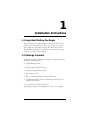
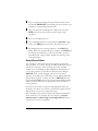
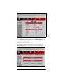
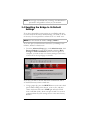
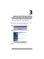
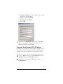
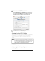
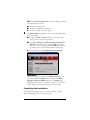
ADSL Modem
U S E R ’ S
M A N U A L
BRIDGE
NOTICE
This document contains proprietary information protected by copyright, and
this Manual and all the accompanying hardware, software, and
documentation are copyrighted. No part of this document may be
photocopied or reproduced by mechanical, electronic, or other means in
any form.
The manufacturer does not warrant that the hardware will work properly in
all environments and applications, and makes no warranty or representation,
either expressed or implied, with respect to the quality, performance,
merchantability, or fitness for a particular purpose of the software or
documentation. The manufacturer reserves the right to make changes to the
hardware, software, and documentation without obligation to notify any
person or organization of the revision or change.
All brand and product names are the trademarks of their respective owners.
© Copyright 2003
All rights reserved.
Contents
1 INSTALLATION INSTRUCTIONS ................................... 4
1.1
1.2
1.3
1.4
IMPORTANT! BEFORE YOU BEGIN .......................................... 4
PACKAGE CONTENTS .......................................................... 4
QUICK START INSTRUCTIONS ............................................... 5
IF YOU NEED HELP............................................................ 7
2 SYSTEM ADMINISTRATION .......................................... 8
2.1
2.2
2.3
2.4
2.5
MONITORING SYSTEM STATUS ............................................. 8
MONITORING ADSL STATUS ............................................... 8
PERFORMING SYSTEM ADMINISTRATION TASKS........................10
RESETTING THE BRIDGE TO ITS DEFAULT SETTINGS .................11
UPDATING THE BRIDGE’S FIRMWARE .....................................12
3 REMOVING THE BRIDGE MODEM ............................... 13
APPENDIX A: FRONT AND BACK PANEL DATA............... 14
APPENDIX B: USING THE BRIDGE WITH PPPOE ........... 16
APPENDIX C: CUSTOM INSTALLATION INSTRUCTIONS 17
APPENDIX D: REGULATORY INFORMATION ................. 27
1
Installation Instructions
1.1 Important! Before You Begin
Before installing your ADSL Bridge, you must have DSL service
enabled on your telephone line. To do this, you need to sign up
with a DSL service provider. The provider will arrange to have
DSL enabled and provide you with the communications settings
necessary to log on to their network.
1.2 Package Contents
In addition to these installation instructions, your package should
include the following items:
•
ADSL Bridge modem
•
Power adapter and power cord
•
Straight-through Ethernet cable
•
RJ-11 phone cord
•
RJ-11-to-wall-jack adapter (certain models only)
•
CD-ROM, including software and Warranty and Customer
Support information
•
Phone filter(s) (certain models only).
If anything is missing or damaged, please contact your supplier.
4
Zoom ADSL Bridge Modem User’s Manual
You Will Also Need
•
A Windows, Macintosh, Linux, or other computer that
supports TCP/IP and that is equipped with a Network
Interface Card (NIC).
•
A telephone wall jack to plug the Bridge into. The associated
phone line must be DSL enabled.
1.3 Quick Start Instructions
Default Communication Settings
VPI
VCI
Protocol (Encapsulation)
0
35
Bridge LLC (RFC 1483)
•
If your service provider uses all three default settings listed
above (the majority do), proceed to Connect the Bridge
below.
•
If your service provider uses the default VPI and VCI
numbers but the PPPoE protocol rather than the Bridge
protocol, turn to the Appendix on page 16.
•
If your service provider uses settings different from these
default ones (you would have been told this information when
you signed up with your DSL provider), turn to the
Appendix on page 17.
Connect the Bridge
To connect the Bridge modem hardware, all connections originate
from the Bridge’s back panel.
PWR
ON OFF
RESET
ETHERNET PHONE ADSL
(For reference, we have included a table that defines these back
panel ports, or jacks; see page 14.)
1
Your computer should be off. Plug one end of the supplied
phone cord into the unit’s ADSL jack and the other end into
the ADSL wall jack.
Chapter 1: Installation Instructions
5
2
3
4
5
6
Plug one end of the straight-through Ethernet cable into the
modem’s ETHERNET jack and plug the other end into your
computer’s corresponding Ethernet port.
Plug one end of the included power adapter into the unit’s
PWR jack and the other end into a power strip or wall
receptacle.
Turn your computer back on.
Turn the Bridge modem on by pushing the ON/OFF toggle
switch. The PWR light on the unit’s front panel turns on.
The Bridge performs a startup sequence—the LINK light
blinks. When the startup sequence is complete, the LINK light
will change from blinking to solid. (For reference, we have
included a table on page 14 that explains the meaning of the
front panel lights.)
Using Phone Filters
You should use a filter with each device—phone, fax machine,
analog modem, etc.—that is sharing the DSL-enabled line, because
this prevents the device from receiving noise when the DSL
modem is on. Your Bridge modem includes an onboard filter, so
you can plug a phone or other device directly into the Bridge’s
PHONE jack if you like. Plugging a device into this jack is
optional, not required. For other devices on the DSL-enabled line,
plug the device’s phone cord into the filter’s PHONE end, and
plug the filter’s LINE end into the wall jack. Some Bridge models
come with filters, and more can be purchased from a retailer or
service provider.
Now that your modem is connected and appropriate filters are
attached, you’re done. To connect to the Internet, simply click the
Web browser icon on your computer desktop.
The remainder of this manual contains information intended for
future reference—for example, there are chapters on System
Administration and Removing Your Bridge Modem. Refer to
the Table of Contents for guidance.
6
Zoom ADSL Bridge Modem User’s Manual
1.4 If You Need Help
•
If you have hardware installation problems, our Technical
Support Staff will be happy to assist you.
Windows Users: Please see the Customer Support portion of
the CD for contact information. You may also want to refer to
the Frequently Asked Questions on the CD.
Macintosh and Linux Users: You will find Customer
Support information and Documentation in Adobe PDF
format in the appropriately named folders in the CD-ROM’s
directory.
•
If you have DSL service problems, you should contact your
DSL service provider
Chapter 1: Installation Instructions
7
2
System Administration
Using the computer attached to the Bridge modem and a Webbased browser such as Netscape Communicator or Internet
Explorer, you can administer your Bridge unit and monitor your
ADSL connection.
2.1 Monitoring System Status
If you want to check the overall system status, click the System
Status icon at the top of the Bridge’s main interface page. If the
Bridge’s main interface page isn’t open, click your desktop Web
browser icon and type http://10.0.0.2 to display the Bridge’s main
page.
2.2 Monitoring ADSL Status
If you want to check the status of your ADSL connection, click the
ADSL Status icon at the top of the Bridge’s main interface page.
8
Zoom ADSL Bridge Modem User’s Manual
From here, you can verify whether your ADSL connection is active
or not (ADSL Line State Status will read SHOWTIME). You
can also monitor related ADSL parameters; for example, how fast
the Bridge is transferring data.
If you want to review other network status aspects, click the
Advanced Setup icon at the top of the main interface page.
Chapter 2: System Administration
9
Under the Status heading, you will see ATM Status and TCP
Status buttons. Clicking these buttons displays pertinent, real-time
information. (This information can be useful if a technician needs
to troubleshoot your Bridge connection.)
2.3 Performing System Administration
Tasks
To change system administration-type settings, click the Advanced
Setup icon at the top of the main user interface page. Under the
Administration heading, you will see items such as Admin
Password and System Log.
For example, you can
•
Change the Admin Password:
Type the new password, then retype it for verification
purposes. Note: The password must be at least 8 characters. If
you change your password and then forget it, your only
recourse is to reset it to the default by performing a hardware
system reset (see page 11).
•
View System Log or write log information to a file.
Click this button to view a log of system activity.
•
Perform a Diagnostic Test.
The Bridge’s user interface uses a few basic buttons, which are
listed in the table below.
Button
Function
Save Changes
Clicking this button initiates new settings and
changes.
Write Settings to
Flash and Reboot
Clicking this button puts new settings and
changes into effect—and restarts the unit.
(Changes do not become effective until unit is
restarted.)
Help
Clicking the Help icon at the top of any page
displays context-sensitive help.
10
Zoom ADSL Bridge Modem User’s Manual
Note: We strongly recommend that you change the administrator
password to safeguard the security of your network.
2.4 Resetting the Bridge to Its Default
Settings
If you have changed the system settings on your Bridge and want
to restore them to the factory default settings, you can do so in one
of two ways: You can perform a software reset or a “hard” reset.
Note: The unit’s default IP address is http://10.0.0.2.
If you can open your Web browser and access your Bridge’s user
interface, initiate a software reset:
•
From the Advanced Setup page, under Administration, click
Reset to Default. You will be prompted to click the Write
Settings to Flash and Reboot button. Once this process is
complete, your unit is reset to its factory settings. Click on any
of the icons at the top of page to continue.
If you lose your link to the unit and cannot communicate with it
via the Web browser, initiate a hard reset.
•
Using a paper clip, press the RESET button on the unit’s back
panel. While holding in this button, count to five, and then
release the button. The unit’s LINK light will turn off and
then it will blink slowly, about once per second. You are now
guaranteed that all system settings are set to the unit’s factory
defaults.
Chapter 2: System Administration
11
2.5 Updating the Bridge’s Firmware
To upgrade the Bridge’s firmware, click the Advanced Setup icon
at the top of the main interface page and then follow these steps.
1
2
3
4
You must first download the upgrade (for example, from our
web site or a floppy disk). Save it under a filename with a .dlf
extension.
Click the Firmware Update button and then click Image
Download. The modem will restart itself and switch into
download mode.
Click Browse and select the upgrade file.
Click Upload. The modem will restart itself when the upload is
done. The front panel LINK light will go off during the
rebooting process. Then it will blink and finally remain on
steady; the process is now complete. Note: This process may
take up to a minute.
VERY IMPORTANT!
Do not turn off the Bridge or unplug it while you are
upgrading the firmware or while the unit is in download
mode.
5
12
Close and re-open your Web browser and resume your
Internet session.
Zoom ADSL Bridge Modem User’s Manual
3
Removing the Bridge Modem
If you have installed the Bridge modem software and want to
remove it—for instance, if you move your computer to a
location without ADSL service—follow the steps below.
1
From the desktop, select Start | Programs | Zoom ADSL
Modem | Uninstall Ethernet ADSL Modem.
2
When prompted to confirm your choice, click Yes.
3
When the process is complete, you will be prompted to click
Finish.
4
You can now unplug your modem hardware.
Chapter 3: Removing the Bridge
13
Appendix A
Front and Back Panel Data
Back Panel
The back panel of your unit looks like this.
PWR
ON OFF
RESET
ETHERNET PHONE ADSL
The table below defines the purpose of these ports, or jacks.
Port
Description
PWR
Port to connect the unit to the power adapter.
ON/OFF
Toggle switch to turn the unit on or off.
RESET
Button to reset the unit to its system default settings.
ETHERNET Port to connect the unit to the Ethernet (10BaseT) port of a
computer.
PHONE
Port to connect a phone to the unit.
ADSL
Port to connect the unit to the ADSL telephone wall jack.
Front Panel
The front panel of your unit looks like this.
14
Zoom ADSL Bridge Modem User’s Manual
The table below defines these front panel lights and how to
interpret them.
Light Description
LAN
Lights when LAN connection is active.
RXD
Blinks when unit is transmitting or receiving data.
LINK
Blinks when unit is performing its startup sequence; stays on
solid when unit is connected to the ADSL line.
PWR
Lights when power switch on back panel is turned on.
Appendix A: Front and Back Panel Data
15
Appendix B
Using the Bridge with PPPoE
This Appendix is intended for those users whose service
provider uses the PPPoE protocol, rather than the default
Bridge protocol. You should be aware of the following
alternatives.
• You can connect your Bridge modem to a computer that has
PPPoE client software installed on it. (In most cases, your
service provider will supply this software.)
•
You can connect your Bridge modem to a Gateway that has
built-in PPPoE client software.
Your service provider can advise you, or you can consult the
documentation that came with your computer or Gateway.
Note: Your provider will give you a User Name and Password, so
make sure you have them at hand, because you will need them to
complete the installation.
User Name _________________________
Password __________________________
16
Zoom ADSL Bridge Modem User’s Manual
Appendix C
Custom Installation Instructions
Most users will follow the installation instructions on page 5.
Follow these instructions only if your service provider is using
settings that are different than the default settings listed on that
page.
This custom installation involves the following tasks:
• Setting up the Bridge
• Changing the TCP/IP settings
• Connecting the Bridge
• Establishing communication
• Completing the installation.
Setting Up the Bridge
1
Macintosh, Linux, Windows NT, and 95 Users:
You do not need to run the CD-ROM software.
Skip to Step 2.
Windows 98/98SE, Me, 2000, and XP Users:
a Insert the supplied CD-ROM into your computer. The CD
starts automatically and the Main Menu opens: (Note: If
the CD does not start automatically, from the desktop, go
to Start | Run and then type D:\setup.exe, where D is
the letter of your CD-ROM drive.)
Appendix C: Custom Installation Instructions
17
b Click the ADSL Modem Installation Wizard button.
The software installation proceeds automatically.
c
2
When the process is complete, you will be prompted to
click Finish and shut down your computer.
Now connect the modem hardware. All connections originate
from the Bridge modem’s back panel.
PWR
ON OFF
RESET
ETHERNET PHONE ADSL
(For reference, we have included a table that defines these back
panel ports, or jacks; see page 14.)
a
b
c
18
Your computer should be off. Plug one end of the supplied
phone cord into the unit’s ADSL jack and the other end into
the ADSL wall jack.
Plug one end of the straight-through Ethernet cable into the
modem’s ETHERNET jack and plug the other end into your
computer’s corresponding Ethernet port.
Plug one end of the included power adapter into the unit’s
PWR jack and the other end into a power strip or wall
receptacle.
Zoom ADSL Bridge Modem User’s Manual
d
e
f
Turn your computer back on.
Turn the Bridge modem on by pushing the ON/OFF toggle
switch. The PWR light on the unit’s front panel turns on.
The Bridge performs a startup sequence—the LINK light
blinks. When the startup sequence is complete, the LINK light
will change from blinking to solid, indicating the DSL
connection is successful. (For reference, we have included a
table on page 14 that explains the meaning of the front panel
lights.)
Note: These TCP/IP instructions and screenshots are typical of a
computer using Windows 2000 or XP; if you are using
Windows 98 or Me, yours may differ slightly. If you are a
Macintosh or Linux user, turn to page 20 or 23,
respectively.
Changing the Windows TCP/IP Setting
1
Click Start | Settings | Control Panel and then double-click
the Network icon to display the Network dialog box.
Click the Configuration tab, highlight TCP/IP, and then
click Properties to display the TCP/IP Properties dialog
box.
2
Make sure you are at the IP Address tab. Click the button
Use the following IP address and enter these addresses:
Appendix C: Custom Installation Instructions
19
•
IP address=10.0.0.3 (or any IP address higher than the
Bridge’s 10.0.0.2 IP address)
• Subnet mask=255.255.255.0
• Default gateway=10.0.0.2.
Then click OK.
3
You will see the Network dialog box again. Click OK to
enable your settings. If prompted to do so, insert your
Windows CD-ROM and click OK.
Changing the Macintosh TCP/IP Setting
Depending on your Mac OS, the directions to configure your
Macintosh’s network settings will differ. For OS X, follow the
instructions on page 22. Otherwise, continue directly below.
For Mac OS 7.6.1 - 9.2.2 and Above but not OS X
1
From the Apple menu, choose Control Panels and then
TCP/IP to display the TCP/IP dialog box.
2
On the main toolbar, from the File menu, choose
Configurations.
20
Zoom ADSL Bridge Modem User’s Manual
3
In the Configurations dialog box, click Duplicate.
4
The Duplicate Configuration dialog box appears. Type a
name, such as “Zoom ADSL Modem,” and click OK.
5
The Configurations dialog box appears again. Highlight
your new configuration—in our example, Zoom ADSL
Modem—and click Make Active.
Appendix C: Custom Installation Instructions
21
6
In the TCP/IP dialog box, under Connect via:, select
Ethernet.
Under Configure:, highlight Manually from the Configure:
list and then enter the static IP address 10.0.0.3 (or any IP
address higher than the Bridge’s 10.0.0.2 IP address) and the
subnet mask 255.255.255.0.
7
Close the TCP/IP dialog box. You will be asked if you want
to save the changes. Click Save.
For Mac OS X
1
From the Dock, choose System Preferences and then
Network. The Network pane appears.
2
From the Location: drop-down list box, select New
Location…. In the box, type a name of your choosing, such
as “Zoom ADSL Modem,” and click OK.
3
Under the Show: drop-down tab, choose Built-in Ethernet
or Ethernet.
22
Zoom ADSL Bridge Modem User’s Manual
4
5
Make sure that the TCP/IP tab is foremost.
Highlight Manually in the Configure: menu and then enter
the static IP address 10.0.0.3 (or any IP address higher than
the Bridge’s 10.0.0.2 IP address) and the subnet mask
255.255.255.0.
Click Save and close the Network pane.
Changing the Linux TCP/IP Setting
The instructions for setting up boot-time DHCP vary dramatically
by distribution, so you may want to refer to your particular
version’s documentation. We have included instructions for
RedHat.
Note: If you have other network cards installed, you will need to
pick distinct Ethernet identifiers for each (eth0, eth1, eth2,
etc.). If you select an identifier other than eth0 for your
ADSL modem, use that identifier throughout.
For RedHat
To use a static IP address, edit or create
/etc/sysconfig/network-scripts/ifcfg-eth0 so that it contains
the following lines:
Appendix C: Custom Installation Instructions
23
DEVICE=eth0
ONBOOT=yes
BOOTPROTO=static
IPADDR=10.0.0.3
NETMASK=255.255.255.0
NETWORK=10.0.0.2
Note: If your computer won’t always be on a network with
working DNS at boot-time, set ONBOOT=no. If you
don’t, RedHat 6.2 (and possibly other versions) might
hang. To activate the card by hand when you have
attached your computer to the network, at root, run the
command: /sbin/ifup eth0.
Establishing Communication with the Bridge
1
Windows 98/98SE, Me, 2000, and XP Users:
Once you’ve run the CD and connected the hardware, there
should be a Zoom Web Console icon on your desktop.
Double-click it to display the Network Password dialog box.
Macintosh, Linux, Windows NT, and 95 Users:
There will not be a Zoom Web Console icon on your
desktop. Instead, open your Web browser, type
http://10.0.0.2 and press Enter to display the Network
Password dialog box.
Note: This User Name and Network Password are different
from the ones that your service provider gave you.
They provide an added level of security that protects
your ADSL unit’s settings.
•
User Name=admin
•
Password=zoomadsl
Remember: The User Name and Password letters are casesensitive.
24
Zoom ADSL Bridge Modem User’s Manual
Tip: If the Network Password box doesn’t display, perform
the following in this order:
a Recheck all connections.
b Restart the modem and computer.
c Perform a “hard” reset. (See page 11.)
2
The Basic Setup page displays. You are now communicating
with your Bridge.
a Change the VPI and VCI numbers so that they match
those given by your service provider.
b Click Save Changes and Write Settings to Flash and
Reboot. Once the reboot is complete and the unit has
reset itself—when the front panel’s LINK light remains
on steady again—close the Zoom Web Console page.
c Continue below with Completing the Installation.
REMEMBER:
Any time you make a change to the Basic Setup page, you
must click the Save Changes button and then the Write
Settings to Flash and Reboot button. A Confirm page
displays; click the button to complete the process. If not, the
change will be lost when you navigate to another page.
Completing the Installation
To complete the Bridge setup, you need to re-adjust your IP
address, depending on your service provider.
Appendix C: Custom Installation Instructions
25
•
If your service provider has instructed you to use a dynamic
IP address:
— Be sure to select DHCP or Obtain an IP address
automatically. (Refer to page 19 if you have forgotten how
to access the TCP/IP Properties box.)
•
If your service provider has instructed you to use a specific IP
address:
—Enter the static IP address and subnet mask you have
been given. (Refer to page 19 if you have forgotten how to
access the TCP/IP Properties box.)
That’s it! You can now connect to the Internet by clicking the Web
browser icon on your computer desktop. For instructions on using
phone filters, turn to page 6.
26
Zoom ADSL Bridge Modem User’s Manual
Appendix D
Regulatory Information
U.S. FCC Part 68 Statement
This equipment complies with Part 68 of the FCC rules and the requirements
adopted by the ACTA. The unit bears a label on the back which contains among
other information a product identifier in the format US:AAAEQ##TXXXX. If
requested, this number must be provided to the telephone company.
This equipment uses the following standard jack types for network connection:
RJ11C.
This equipment contains an FCC compliant modular jack. It is designed to be
connected to the telephone network or premises wiring using compatible modular
plugs and cabling which comply with the requirements of FCC Part 68 rules.
The Ringer Equivalence Number, or REN, is used to determine the number of
devices which may be connected to the telephone line. An excessive REN may
cause the equipment to not ring in response to an incoming call. In most areas, the
sum of the RENs of all equipment on a line should not exceed five (5.0).
In the unlikely event that this equipment causes harm to the telephone network,
the telephone company can temporarily disconnect your service. The telephone
company will try to warn you in advance of any such disconnection, but if advance
notice isn't practical, it may disconnect the service first and notify you as soon as
possible afterwards. In the event such a disconnection is deemed necessary, you
will be advised of your right to file a complaint with the FCC.
From time to time, the telephone company may make changes in its facilities,
equipment, or operations which could affect the operation of this equipment. If
this occurs, the telephone company is required to provide you with advance notice
so you can make the modifications necessary to obtain uninterrupted service.
There are no user serviceable components within this equipment. See Warranty
flyer for repair or warrantee information
It shall be unlawful for any person within the United States to use a computer or
other electronic device to send any message via a telephone facsimile unless such
message clearly contains, in a margin at the top or bottom of each transmitted
page or on the first page of the transmission, the date and time it is sent and an
identification of the business, other entity, or individual sending the message and
the telephone number of the sending machine or of such business, other entity, or
individual. The telephone number provided may not be a 900 number or any
other number for which charges exceed local or long distance transmission
charges. Telephone facsimile machines manufactured on and after December 20,
1992, must clearly mark such identifying information on each transmitted
Appendix D: Regulatory Information
27
message. Facsimile modem boards manufactured on and after December 13, 1995,
must comply with the requirements of this section.
This equipment cannot be used on public coin phone service provided by the
telephone company. Connection to Party Line Service is subject to state tariffs.
Contact your state public utility commission, public service commission, or
corporation commission for more information.
U.S. FCC Part 15 Emissions Statement
This equipment has been tested and found to comply with the limits for a Class B
digital device, pursuant to part 15 of the FCC Rules. These limits are designed to
provide reasonable protection against harmful interference in a residential
installation. This equipment generates, uses and can radiate radio frequency and, if
not installed and used in accordance with the instructions, may cause harmful
interference to radio communications.
However, there is no guarantee that interference will not occur in a particular
installation. If this equipment does cause harmful interference to radio or
television reception, which can be determined by turning the equipment off and
on, the user is encouraged to try to correct the interference by one or more of the
following measures:
•
Reorient or relocate the receiving antenna.
•
Increase the separation between the equipment and receiver.
•
Connect the equipment into an outlet on a circuit different from that to
which the receiver is connected.
•
Consult the dealer or an experienced radio/TV technician for help.
Declaration of Conformity
The manufacturer declares under sole responsibility that this equipment is
compliant to Directive 1999/5/EC (R&TTE Directive) via the following:
Directive
Standard
Test Report
rd
73/23/EEC-Low
Voltage
IEC 60950: 3 ed. 1999
89/336/EEC-EMC
EN 55024: 1998
89/336/EEC-EMC
ed
ed
EN 55022 : 1998
electrical safety
EMC-immunity
EMC-emissions
This product is CE Marked.
Electrostatic Discharge Statement
The unit may require resetting after a severe electrostatic discharge event.
Additional compliance information is included on the CD.
28
Zoom ADSL Bridge Modem User’s Manual
3143-A
27293
©2003
3143-A
27293
©2003