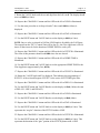
1
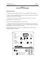
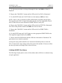
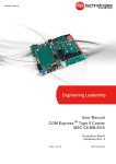
ITW Dynatec An Illinois Tool Works Company 31 Volunteer Drive Hendersonville, TN 37075 USA Telephone 615.824.3634 FAX 615.264.5222 ITW Dynatec GmbH Industiestrasse 28 D-40822 Mettmann, Germany Telephone 49.2104.915.0 FAX 49.210.2104.915.111 OPERATIONS & SERVICE MANUAL Manual 50 -05 Revised 1/23/04 ITW Dynatec K.K. Daiwashinagawa Bldg., 7-15 Konan, 3-Chome Minata-Ku, Tokoyo 108 Japan Telephone 81.3.3450.5901 FAX 81.3.3450.8405 Adhesive Application Solutions · ISO 9001 Certified TPC2 TIME-BASED PATTERN CONTROL KIT OPERATIONS AND SERVICE MANUAL PN 106082: 115v PN 106083: 230v Memory Event Drive 1 Delay Drive 2 Line A.T.S. Gap (Spot / Stitch) Trigger Stitch Spike Time 1 Purge Channel / Drive 2 Value Digit Trig Mode Time Range Glue / Pass / Start Palletising Count System Unlocked Run / Stop TPC-2 Drive 1 Drive 2 Trigger ATS Purge T630mA Isolate From Supply Before Removing Access Cover IMPORTANT ! - READ ALL INSTRUCTIONS BEFORE OPERATING THIS EQUIPMENT It is the customer’s responsibility to have all operators and service personnel read and understand this information. Contact your ITW Dynatec customer service representative for additional copies. NOTICE! Please be sure to include the serial number of your equipment each time you order replacement parts and/or supplies. This will enable us to send you the correct items that you need. ITW Dynatec Service Parts Direct Dial: 1-800-538-9540 ITW Dynatec Technical Service Direct Dial: 1-800-654-6711 Page ii Revised 1/99 ITW Dynatec An Illinois Tool Works Company Adhesive Application Solutions c. 1999 TPC-2 TIMER Manual 50-05 ITW Dynatec c. 1999 TPC-2 TIMER Manual #50-56 Page iii Revised 1/99 TABLE OF CONTENTS CHAPTER 1:DESCRIPTION General Description ...................................................................................................................................... 1-1 Specifications................................................................................................................................................ 1-2 How to Use this Manual................................................................................................................................ 1-2 CHAPTER 2: INSTALLATION Unpacking ..................................................................................................................................................... 2-1 Supplied Equipment...................................................................................................................................... 2-2 Optional Accessories..................................................................................................................................... 2-3 Changing AC Input Voltage.......................................................................................................................... 2-3 Dimensions ................................................................................................................................................... 2-5 Locating the TPC-2 for Installation .............................................................................................................. 2-5 Installing the TPC-2 and Accessories ........................................................................................................... 2-6 230VAC Power Cord Wiring........................................................................................................................ 2-7 Receptacle Assignments................................................................................................................................ 2-7 Important Note .............................................................................................................................................. 2-8 CHAPTER 3: OPERATION AND PROGRAMMING Start-up Procedure ........................................................................................................................................ 3-1 Programming Conventions............................................................................................................................ 3-2 System Status Lights ..................................................................................................................................... 3-3 Drive 1 & Drive 2 ..................................................................................................................................... 3-3 A.T.S. .................................................................................................................................................. 3-3 Trigger .................................................................................................................................................. 3-4 Programming SYSTEM Parameters ............................................................................................................. 3-4 Purge .................................................................................................................................................. 3-4 Trig Mode ................................................................................................................................................. 3-5 Time Range ............................................................................................................................................... 3-5 Glue/Pass/Start ......................................................................................................................................... 3-6 Palletising Count ...................................................................................................................................... 3-7 Selecting a Program from MEMORY........................................................................................................... 3-8 Programming Glue Pattern (CHANNEL) Parameters................................................................................... 3-8 Event .................................................................................................................................................. 3-8 Delay .................................................................................................................................................. 3-9 Line .................................................................................................................................................. 3-11 Gap .................................................................................................................................................. 3-11 Stitch .................................................................................................................................................. 3-13 Spike Time................................................................................................................................................. 3-14 Clearing Programmed Information ............................................................................................................... 3-14 CHAPTER 4: EXAMPLES Purge CHANNEL 1 and CHANNEL 2......................................................................................................... 4-1 A Single EVENT Glue Pattern ..................................................................................................................... 4-2 A Multiple EVENT Glue Pattern.................................................................................................................. 4-3 Page iv Revised 10/99 ITW Dynatec c. 1999 TPC-2 TIMER Manual #50-05 CHAPTER 5: TROUBLESHOOTING Controller Glues Every Other Sheet.............................................................................................................. 5-1 GlueLine Moves or Changes Length............................................................................................................. 5-1 Glue Applicators Will Not Activate.............................................................................................................. 5-1 DRIVE or A.T.S. Status LED is Illuminated Red ......................................................................................... 5-2 Program Parameters Can Not Be Modified................................................................................................... 5-3 SYSTEM Parameters Can Not Be Accessed ................................................................................................ 5-3 Glue Pattern Repeats Itself on the Product.................................................................................................... 5-3 CHAPTER 6: INSTALLATION & MAINTENANCE Replacement Parts......................................................................................................................................... 6-1 Typical System Diagrams ............................................................................................................................. 6-1 Electrical Schematics .................................................................................................................................... 6-3 TPC-2 Hot Melt System Overview Bill of Materials .................................................................................... 6-4 TPC-2 Hot Melt System Overview Installation Illustration .......................................................................... 6-5 TPC-2 Hot/Cold Glue System Overview Bill of Materials ........................................................................... 6-6 TPC-2 Hot/Cold Glue System Overview Installation Illustration ................................................................. 6-7 Timing Nomograph....................................................................................................................................... 6-8 ITW Dynatec c. 1999 TPC-2 TIMER Manual #50-05 Page 1 - 1 Revised 11/04 Chapter 1 DESCRIPTION Description The ITW Dynatec TPC-2 Timer is a microprocessor-based electronic control system. It may be used in any process that requires the timed actuation of electrical output devices and has the ability to count those actuations and take varied actions based upon the count. It was specifically developed to control glue application valves used in adhesive systems. Examples of applications where the TPC-2 may be used include, but are not limited to, case sealing, palletizing, labeling, and bag making. The TPC-2 can be operated on either 120vac or 240vac (single phase) power. A set of contacts is provided to allow a signal to be sent to an external controller (such as a PLC) when the TPC-2 is switched on. All controls and displays are mounted inside a rugged enclosure with a protective door. The enclosure meets environmental ratings of IP54, protecting against water and solid object infiltration when the door is latched and all output/input receptacles at the bottom of the TPC-2 Control Unit are either connected to cables or capped. The TPC-2 display is a bright, seven-segment LED device that affords easy viewing at any angle and in any lighting environment. All connectors are standardized to simplify installation. The TPC-2 Timer has non-volatile memory for up to four programs. Each program has two CHANNEL outputs. Each CHANNEL is independent of the other and has four programmable EVENTS. An EVENT is defined as a DELAY (no glue) and a LINE (glue). Each LINE may be programmed to apply continuous glue or apply in a STITCH (series of dashes) or SPOT (series of dots) pattern. Programming is accomplished by depressing the appropriate CHANNEL or SYSTEM button until the desired parameter LED is illuminated on the left side of the display panel. Depressing the DIGIT button causes the values on the display to flash. Rotating the VALUE knob modifies the displayed value. Depressing the RUN/STOP button so the LED is illuminated signifies the glue system is active and will respond to trigger inputs. Activity of the DRIVE 1, DRIVE 2 and A.T.S. (Automatic Tip Sealer) outputs or the TRIGGER input is indicated in the top right corner of the display via illumination of the respective LED’s. Facilities for a remote PURGE device (supplied standard with the system) and Automatic Tip Sealers (used in cold glue systems) offer the operator ease of glue system maintenance during times of system inactivity. The Automatic Tip Sealer (A.T.S.) Drive output is provided for use with cold glue systems that may employ tip sealing devices to prevent the glue from drying in the applicator nozzle during periods of glue system inactivity. Pattern initiation may be set for any of four trigger modes: Gated Repeat, Latched Repeat, Gated Single, and Latched Single. See Chapter 2 (Operation and Programming) for further information concerning TRIGGER MODE. Page 1 - 2 Revised 1/99 ITW Dynatec c. 1999 TPC-2 TIMER Manual #50-05 The TPC-2 possesses a PALLETISING facility that provides an easy means of applying glue to a specified number of objects, then passing (or skipping) a specified number of objects. The display continually updates itself to inform the operator of the current COUNT. A key-actuated system lock is provided on the Controller’s front panel. This lock prevents any unauthorized change to the programming when activated. Specifications Operating Temperature: 32 to 113 degrees F (0 to 45 degrees C), 0 to 90% RH, non-condensing Storage Temperature: -14 to 140 degrees F (-10 to 60 degees C), 0 to 90% RH, non-condensing Maximum Switching Rate: 500 cycles per second Maximum Power Output: 26 Watts, current limited at 1.25 amps per channel Applicator Overload Protection: Electronic Sensing Time Increments: 0.001 to 1.999 seconds or 0.01 to 19.99 seconds (operator selectable) Holding Voltage: 16 VDC Over-Voltage: 48 VDC Over-Voltage Duration: 0 to 25.5ms, operator selectable Input Voltage: 115 or 230 VAC ± 10% (requires installation of appropriate jumper), single phase Input Power: 60 Watts How to Use this Manual The following typographic conventions are used throughout this manual: ALL CAPITALS: Parameter, Button and Knob titles displayed on the TPC-2 Control Unit Display Panel Bold: Information found on the TPC-2 Control Unit’s LED Display ITW Dynatec c. 1999 TPC-2 TIMER Manual #50-05 Page 2 - 1 Revised 8/99 Chapter 2 INSTALLATION The ITW Dynatec TPC-2 Timer is very easy to install and operate. It is highly recommended, however, that the entire contents of this manual be read before installation to become familiar with the many features of this equipment and to avoid potential safety hazards. WARNING: Line voltage is present at several places inside this Control Unit when it is connected to an AC power source. Electrical shock will result if contact is made with line voltage. This shock may be extremely hazardous. Do not disassemble or assemble this unit or make electrical connections unless all line voltage sources are removed. Unpacking Carefully unpack and inspect the TPC-2 enclosure for external damage. The Control Unit is shipped completely assembled. There should be no rattles or loose pieces inside the unit Page 2 - 2 Revised 1/04 ITW Dynatec c. 1999 TPC-2 TIMER Manual #50-05 Supplied Equipment The TPC-2 Control Kit is supplied with the following equipment. Please inventory these parts immediately upon unpacking the Control Kit to assure all items are present. Qty Description Part Number 1 Control Unit, TPC-2 106076 1 Purge Control 106078 1 Output Kit (contains two 10 foot drive output cables, one end with connector, the other end unterminated) L21754 Security Lock Keys (2 keys) 107189 2 Sealing Cap, 9-pin Receptacle (attached to ATS and DRIVE 2 output connectors) 106023 1 Manual, TPC-2 (the manual you are currently reading) 1 set 50-05 TPC-2 Control Unit Security Lock Keys Purge Control Output Cables ITW Dynatec c. 1999 TPC-2 TIMER Manual #50-05 Page 2 - 3 Revised 11/04 Optional Accessories The following accessories are available from ITW Dynatec for use with the TPC-2 Control Kit: Description Part Number Mini Reflective Photo Sensor Assembly, 2ms Response (6’ cord) L21746 Reflective Photo Sensor Assembly, 1ms Response (6’ cord) L21701 Fiber Optic Photo Sensor Assembly (6’ cord) L21745 Foot Switch Assembly (10’ cord) 106114 Trigger Extension Cable, 10’ (may be used with any of the above photo sensors or foot switch assembly) L21747 Sealing Cap, 4-Pin Receptacle (seals unused 4-pin connectors for IP54 integrity) 106116 Sealing Cap, 9-Pin Receptacle (seals unused 9-pin connectors for IP54 integrity) 106023 Quad Head Cord, 10’ (allows connection of up to four applicators to a single drive output) 106004 Dual Head Cord, 10’ (allows connection of up to two applicators to a single drive output) 106005 Single Head Cord, 10’ (allows connection of a single applicator to a drive output, used primarily with cold glue applicators) 106006 Solenoid Cord, RCA(M)/Unterminated, 10’ (used with 106004, 106005 or 106006) 340-010-XA Solenoid Cord, RCA(M)/RCA(F), 10’ (used with 106004, 106005 or 106006) 340-010-AA Changing AC Input Voltage WARNING: Changing the operating voltage requires access to the TPC-2 Control Unit’s internal power supply. Only qualified maintenance technicians should attempt this procedure. The TPC-2 Control Unit is capable of operating from 115VAC or 230VAC input voltage. Your unit has been factory pre-set to one of these voltages. There should be a sticker attached to the lower left corner of Control’s front panel, just above the power switch, identifying the factory-set voltage. WARNING: Disconnect the TPC-2 from its power source before attempting this procedure. Page 2 - 4 Revised 11/04 ITW Dynatec c. 1999 TPC-2 TIMER Manual #50-05 The following steps should be employed to change the Control Unit’s operating voltage from the factory pre-set value: 1. Remove the 6 screws that secure the upper and lower portions of the Control Unit display panel using a cross-point screwdriver. 2. Remove the lower panel (the portion housing the power switch and fuse holder) from the case taking care not to strain the wires connected to the backside of the panel. 3. Remove the upper panel from the case taking care not to strain the wires connected to the backside of the panel. 4. A printed circuit board (PCB) is mounted at the upper left corner inside the Control Unit case. This board contains a two-position, red, voltage selection switch. Slide the switch to the desired voltage. 5. Reverse Steps 1 through 3 to re-assemble the Control Unit taking care not to pinch any wires during the process. Remove lower panel first Seletor Switch ITW Dynatec c. 1999 TPC-2 TIMER Manual #50-05 Page 2 - 5 Revised 8/99 Dimensions 1.19" 30mm 5.25” 133.4mm 11.56" 294mm 3.5" 89mm 3.5" 89mm 1.19" 30mm 0.27" 7mm 11.56" 294mm 10.81" 275mm .375" 10mm 9.75" 248mm .5" 13mm Locating the TPC-2 for Installation Mount the TPC-2 in a cool, dry, clean and well-ventilated area. Allow access space at the front and sides for operation and maintenance. Do not place the Control Unit where it is subject to high heat and humidity, in traffic areas or where it could be subject to mechanical abuse. Do not mount the TPC-2 Control Unit or any of its components/accessories close to high power wiring or in close proximity to sources of RF or static energy. CAUTION: 1. Heat, humidity and mechanical abuse will impair the performance and shorten the life of Control Unit components. 2. Do not mount the TPC-2 Control Unit or its accessories near high voltage power lines or in close proximity of radio frequency interference (such as arc welding or electric motors), as this may cause irregular operation. Page 2 - 6 Revised 12/99 ITW Dynatec c. 1999 TPC-2 TIMER Manual #50-05 Installing the TPC-2 and Accessories 1. Mount the TPC-2 Control Unit as close to the Trigger Input Device and the Glue Applicators as is possible. 2. Mount the Trigger Device and Glue Applicator(s) in the desired locations. Connect the Drive Output Cable(s) to the Glue Applicator(s). 3. Install the Automatic Tip Sealer(s) to the Glue Applicator(s) (cold glue systems) and connect the Drive Output Cable(s) to the Automatic Tip Sealer(s). 4. Connect all cables to their proper receptacles on the bottom of the TPC-2 Control Unit. There is a legend along the bottom of the Display Panel (inside the Control Unit lid) indicating the input/output connector assigments. 5. Install Sealing Caps (106116 and/or 106023) to unused receptacles if IP54 integrity is required in the following manner: a. Remove the 2 screws that secure the lower portion of the TPC-2 Control Unit display panel using a cross-point screwdriver. b. Remove the lower panel (the portion housing the power switch and fuse holder) from the case taking care not to strain the wires connected to the backside of the panel. This will allow access to the nuts attaching the receptacle flanges to the Control Unit Case. c. Remove one of the screws attaching each unused receptacle flange and place the screw through the eyelet of the appropriate Sealing Cap tether (106116 is used for the 4-pin and 106023 is used for the 9-pin receptacle). d. Reverse Steps (a) through (c) taking care not to pinch any wires in the process. 6. Connect the TPC-2 Control Unit power cord to a clean, properly grounded power source of the appropriate voltage (115 or 230VAC). Observe wiring, grounding and safety practices in accord with all local electrical codes. The 115VAC version of the TPC-2 comes with a standard 10-amp plug on the end of the cord. The 230VAC version of the TPC-2 has no plug. Instead, bare wires are provided for connection into a terminal box. The wires should be connected as follows: ITW Dynatec c. 1999 TPC-2 TIMER Manual #50-05 Page 2 - 7 Revised 11/04 230VAC Power Cord Wiring WIRE COLOR DESIGNATION Brown or Black Power (+) Blue or White Neutral (-) Green Ground CAUTION: Avoid the installation of input or output cords near or parallel to power lines from other machinery. The resulting electrical “noise” can produce adverse effects on the TPC-2 Control Unit which could result in unreliable operation. Receptacle Assignments Below are the pin assignments for the input/output receptacles located at the bottom of the TPC-2 Control Unit. Drive 1 Drive 2 ATS Trigger Purge 1 2 3 4 5 6 7 8 9 1 2 3 4 PIN ASSIGNMENT RECEPTACLE 5 6 DRIVE 1 minus +16V DC DRIVE 2 minus +16V DC A.T.S. minus +16V DC TRIGGER PURGE 1 +12V DC 2 3 Gnd Signal (NPN) minus +12V DC 4 Chassis Gnd 7 8 NOTE: shorting pins #2 & #3 will manually initiate the trigger. cont. 9 Page 2 - 8 Revised 12/99 ITW Dynatec c. 1999 TPC-2 TIMER Manual #50-05 Important Note: The TPC-2 is usually connected to non-polarity-sensitive solenoids using the ITW Dynatec Output Kit (L21754) supplied as a part of the TPC-2 Control Unit Kit. As such, it is not important to which terminal the two wires of the Output Kit cables are connected. Polarity Sensitive solenoids, such as ITW Dynatec P/N 030A057 require attention to the manner in which the Output Kit wires are connected. It is imperative that the White Wire be connected to the solenoid’s “positive” (+) terminal and the Black Wire be connected to the “negative” (-) terminal. Failure to do so will render the solenoid valve inoperative and may cause damage to both the TPC-2 Control Unit and the solenoid valve. ITW Dynatec c. 1999 TPC-2 TIMER Manual #50-05 Page 3 - 1 Revised 1/99 Chapter 3 OPERATION & PROGRAMMING Start-Up Procedure 1. Open the latch on the right side of the TPC-2 Control Unit and swing open the lid. 2. Two keys for the Programming Security feature should be attached to the inside of the lid. Remove these keys and unwrap them. 3. Insert one of the keys into the lock on the Display Panel. Assure the key is in the UNLOCKED (key tab vertical) position. 4. Remove the key and place both keys in a secure location. 5. Turn ON the Control Unit by depressing the Power Switch in the lower left corner of the Display Panel. The Power Switch is on a “rocker”. The “ ” side of the rocker should be depressed to provide power to the Control Unit. The LED Display should show a Pr-1 (-2, -3 or -4) and the green LED to the left of MEMORY should be illuminated. Memory Event Delay Line Gap (Spot / Stitch) Stitch Spike Time Purge Trig Mode Time Range Glue / Pass / Start Palletising Count Drive Drive A.T.S. Trigger 1 Channel / Drive 2 Value Digit System Run / Stop Unlocked TPC-2 Drive 1 Drive 2 Trigger ATS Purge T630 Isolate From Supply Before Removing Access Cover Page 3 - 2 Revised 1/99 ITW Dynatec c. 1999 TPC-2 TIMER Manual #50-05 Programming Conventions The TPC-2 employs the following programming conventions: 1. All CHANNEL modifications are performed on the Program displayed (Pr-1, -2, -3 or -4) when the MEMORY LED is illuminated. 2. Depressing the CHANNEL 1 or CHANNEL 2 buttons allows programming of the parameters for that channel of the selected Program (Pr-1, -2, -3 or -4). 3. Depressing the SYSTEM button allows programming of the parameters that pertain to the entire glue system, regardless of the Program (Pr-1, -2, -3 or -4) or CHANNEL selected. 4. Depressing the DIGIT button allows selection of the “granularity” of the displayed parameter as it is being modified. (i.e. depressing the DIGIT button until the “100’s” place holder is flashing will result in increments/decrements of 100 units at a time, depressing the DIGIT button until the “1’s” place holder is flashing will result in increments/decrements of single units at a time, etc.). 5. Rotation of the VALUE knob allows the actual modification of displayed values. 6. The glue system will not operate unless the LED above the RUN/STOP button is illuminated. 7. Modification of the CHANNEL parameters while the glue system is operating will result in real-time adjustments to the glue pattern. This allows the operator the ability to “fine-tune” the program settings while the system is operating. 8. No SYSTEM parameters may be accessed while the LED above the RUN/STOP button is illuminated with the exception of the PALLETISING COUNT. 9. Only the active Program (Pr-1, -2, -3 or -4) may be modified while the glue system is operating. ITW Dynatec c. 1999 TPC-2 TIMER Manual #50-05 Page 3 - 3 Revised 1/99 System Status Lights There are four LED’s in the top right corner of the Display Panel that provide an indication of the current system status. These lights are described in further detail below: Drive 1 & Drive 2 These LED’s provide an indication of the current Drive Output activity. The LED’s will be in one of the following states: STATUS LIGHT No Illumination: GREEN: RED: MEANING There is no Drive Output activity The Drive Output is functioning properly and is currently energized There is an electrical short or other fault in the Drive Output, Output Cable or Glue Valve An electrical short circuit most likely exists if a Drive Status Light is red. Completely inspect the Output Cables and Glue Valve for the cause. Turn OFF, then turn back ON the TPC-2 Control Unit to clear the fault condition once the cause of the fault has been located. See the TROUBLESHOOTING section of this manual for more information in the event of a Drive Output fault. A.T.S. The Automatic Tip Sealer output is provided for use with cold glue systems that may employ tip sealing devices to prevent the glue from drying in the applicator nozzle during periods of glue system inactivity. This LED provides an indication of the current A.T.S. Drive Output activity. The LED will be in one of the following states: STATUS LIGHT MEANING No Illumination: There is no A.T.S. Output activity. The A.T.S. Output automatically deactivates when the TPC-2 does not receive a Trigger Input for 2.5 seconds. GREEN: The A.T.S. Output is functioning properly and is currently energized. The A.T.S. Output should activate immediately upon receipt of a Trigger Input. RED: There is an electrical short or other fault in the A.T.S. Output circuitry, Output Cable or Glue Valve An electrical short circuit most likely exists if the A.T.S. Status Light is red. Completely inspect the Output Cable and Tip Sealing Device for the cause. Turn OFF, then turn back ON the TPC-2 Control Unit to clear the fault condition once the cause of the fault has been located. See the TROUBLESHOOTING section of this manual for more information in the event of an A.T.S. Drive Output fault. Page 3 - 4 Revised 1/99 ITW Dynatec c. 1999 TPC-2 TIMER Manual #50-05 The A.T.S. output voltage is 48VDC at 5.4W for a 25ms duration. The output then drops to a holding voltage of 16VDC. The TPC-2 activates the A.T.S. Drive immediately upon receipt of Trigger Inputs. The Tip Sealing Device requires time to operate, the TPC-2 caters for this by allowing a 35ms dwell time from Trigger Input until the gluing program will function. This means that if the first delay time is programmed to be less than 35ms the first glue line will start late then revert to the normal pattern in successive cycles. The A.T.S. Drive output automatically deactivates when the TPC-2 does not receive Trigger Inputs for 2.5 seconds or more. Trigger A Trigger Device of some kind is required to initiate the TPC-2 gluing pattern. The TRIGGER LED is illuminated green when the Trigger Device is activated. Programming SYSTEM Parameters TPC-2 Control Unit functions are modified by depressing the SYSTEM button. Activation of SYSTEM parameters is signified via illumination of the LED above the SYSTEM button and the illumination of the LED to the left of the specific parameter (PURGE, TRIG MODE, TIME RANGE, GLUE/PASS/START or PALLETISING COUNT). NOTES: a. All SYSTEM parameters, with the possible exception of PALLETISING COUNT, are accessible only when the LED above the RUN/STOP button is not illuminated. b. All SYSTEM parameters are stored in “non-volatile” memory, the settings are retained even when TPC-2 Control Unit input power is lost or the power switch is turned off. c. Modification to SYSTEM parameters may only be undertaken when Programming Security is in the UNLOCKED position. Purge The PURGE function requires connection of the Purge Control (106078) into the appropriate receptacle in the bottom of the TPC-2 Control Unit. 1. Depress the SYSTEM button until the red LED to the left of PURGE flashes. The TPC-2 display will indicate = = = 0. 2. Rotate the VALUE knob until the desired PURGE channel is selected. The table below indicates the meaning of each display setting: ITW Dynatec c. 1999 TPC-2 TIMER Manual #50-05 Page 3 - 5 Revised 1/99 PURGE Display Settings DISPLAY MEANING ===0 Activation of A.T.S. output only ===1 Activation of A.T.S. and DRIVE 1 outputs ===2 Activation of A.T.S. and DRIVE 2 outputs 3. Activation of the selected outputs occurs upon depressing the button on the Purge Control Unit (106078) and continues until the button is released. Trig Mode The TRIG MODE (Trigger Mode) parameter allows the Operator to select the manner in which the TPC-2 Control Unit applies the programmed pattern upon receiving a trigger (i.e. photo sensor, footswitch, etc.) input. 1. Depress the SYSTEM button until the yellow LED to the left of TRIG MODE is illuminated. 2. Rotate the VALUE knob until the desired TRIG MODE setting is selected. The table below indicates the meaning of each display setting. TRIG MODE Display Settings DISPLAY MEANING GAt.≡ ≡ Gated Repeat – the trigger signal initiates the glue cycle, which repeats continuously until the trigger signal ends. The glue cycle stops immediately upon loss of trigger signal, regardless of the state of the glue cycle. LAt.≡ ≡ Latched Repeat - the trigger signal initiates the glue cycle, which repeats continuously until the trigger signal ends. The glue cycle stops upon completion of the pattern cycle after loss of trigger signal. GAt.- Gated Single – the trigger signal initiates the glue cycle, a single glue pattern is performed. The glue cycle stops immediately if the trigger signal is lost during the cycle, regardless of the state of the glue cycle. LAt.- Latched Single - the trigger signal initiates the glue cycle, a single glue pattern is performed. The glue cycle stops upon completion of the pattern cycle. Time Range The TPC-2 offers two time ranges for programming of DELAY and LINE settings: 0.001 (i.e. 1ms) to 1.999 seconds and 0.01 (i.e. 10ms) to 19.99 seconds. 1. Depress the SYSTEM button until the yellow LED to the left of TIME RANGE is illuminated. 2. Rotate the VALUE knob until the desired TIME RANGE setting is selected. The table below indicates the meaning of each display setting. Page 3 - 6 Revised 1/99 ITW Dynatec c. 1999 TPC-2 TIMER Manual #50-05 TIME RANGE Display Settings DISPLAY MEANING 0.001 Time Range Selection between 0.001 and 1.999 seconds 0.010 Time Range Selection between 0.01 and 19.99 seconds NOTE: Maximum time settings (i.e. 1.999 or 19.99 seconds) represent the maximum allowed cumulative time for DELAY and LINE duration of all four EVENTs in a CHANNEL Glue/Pass/Start The TPC-2 offers a Palletizing feature that provides the capability of gluing a specified quantity of items, based upon Trigger inputs, then “passing” (allowing sensed product to pass under the applicator with no glue being applied) a specified quantity of items, also based upon Trigger inputs. The Operator can program both the quantity of product to be “glued” and “passed” along with specifying whether the process should begin with the “glue” or the “pass” count. 1. Depress the SYSTEM button until the yellow LED to the left of GLUE/PASS/START is illuminated. The display will show OFF if the Palletizing program in not currently active. Glue 2. Depress the DIGIT button. The display will show G.000 with the digit furthest to the right flashing. This display allows the programming of the quantity of items to be “glued”. Depressing the DIGIT button additional times will change the granularity of the “glued” quantity setting. 3. Rotate the VALUE knob until the desired “glued” quantity is selected. (Example: G.040 indicates that forty consecutive items will be glued). NOTE: Selection of the value G.000 for this parameter will set the palletizing feature to OFF, regardless of any PASS values that may be programmed. Pass 4. Depress the SYSTEM button once. The display will now show P.001 or some other similar value. 5. Depress the DIGIT button. The digit furthest to the right will commence flashing. This display allows the programming of the quantity of items to be “passed”. Depressing the DIGIT button additional times will change the granularity of the “passed” quantity setting. ITW Dynatec c. 1999 TPC-2 TIMER Manual #50-05 Page 3 - 7 Revised 1/99 6. Rotate the VALUE knob until the desired “pass” quantity is selected. (Example: P.010 indicates that ten consecutive items will be passed). Start 7. Depress the SYSTEM button once. The display will now show either GLUE or PASS. 8. Rotate the VALUE knob until the desired value is displayed. The palletizing count will start with either the GLUE or the PASS count depending upon which value is selected for this parameter. Palletising Count The PALLETISING COUNT parameter is a display-only function that allows the operator to track the progress of the palletizing glue process. 1. Depress the SYSTEM button until the yellow LED to the left of PALLETISING COUNT is illuminated. 2. View the status of the palletizing glue process. The PALLETISING COUNT will count down with each trigger signal input: G.040, G.039, G.038, …, G.001, P.010, P.009, P.008, …, P.001, then repeat the cycle; assuming G.040 and P.010 were programmed in GLUE and PASS respectively and the cycle was set to begin with GLUE. Similarly, the cycle would begin counting down the PASS, then the GLUE portion, if the cycle was programmed to begin with PASS. NOTES: a. The PALLETISING COUNT parameter will not be accessible unless the palletizing feature is activated through the programming of values in the GLUE/PASS/START parameter. b. The PALLETISING COUNT is the only SYSTEM parameter that is accessible when the TPC-2 is set to RUN mode (LED above the RUN/STOP button is illuminated), assuming the palletizing feature is activated through the programming of values in the GLUE/PASS/START parameter. c. Any modifications to GLUE/PASS/START parameters will result in the reset of the PALLETISING COUNT. Selecting a Program from MEMORY The TPC-2 Control Unit possesses MEMORY storage capacity for as many as four independent programs. Each of these programs controls up to two independent glue channels or drives. Additionally, each program can possess up to four events with each event being composed of a DELAY and a LINE. The Program MEMORY is “non- Page 3 - 8 Revised 1/99 ITW Dynatec c. 1999 TPC-2 TIMER Manual #50-05 volatile”, the settings are retained even when TPC-2 Control Unit input power is lost or the power switch is turned off. 1. Depress the SYSTEM button until the LED above the button is no longer illuminated and the green LED to the left of the MEMORY parameter is illuminated. 2. Rotate the VALUE knob until the desired Program (Pr – 1 through Pr – 4) is displayed. NOTES: a. The MEMORY setting may only be modified when the TPC-2 Control Unit is in the STOP mode (the LED above the RUN/STOP button is not illuminated). b. Modifications to CHANNEL parameters affect only the active Program selected via the MEMORY parameter. Programming Glue Pattern (CHANNEL) Parameters Programming of a glue pattern into the TPC-2 Control Unit is accomplished by depressing either the CHANNEL 1 or CHANNEL 2 button so that the red LED above the button is illuminated. Activation of CHANNEL parameters is signified via illumination of the LED to the left of the specific parameter (EVENT, DELAY, LINE, GAP, STITCH and SPIKE TIME). NOTES: a. All CHANNEL parameters may be modified regardless of whether the TPC-2 Control Unit is in the RUN or STOP mode. b. All CHANNEL parameters are stored in “non-volatile” memory, the settings are retained even when TPC-2 Control Unit input power is lost or the power switch is turned off. c. Modification to CHANNEL parameters may only be undertaken when Programming Security is in the UNLOCKED position. d. CHANNEL 1 and CHANNEL 2 parameters are independent of each other, however the programming procedure for each CHANNEL is exactly the same. Event Each CHANNEL of each Program has up to four EVENTs. An EVENT is defined as a DELAY (skip) duration followed by a LINE (glue) duration. 1. Depress the desired CHANNEL button until the LED to the left of EVENT is illuminated. ITW Dynatec c. 1999 TPC-2 TIMER Manual #50-05 Page 3 - 9 Revised 1/99 2. Rotate the VALUE knob until the desired EVENT is selected. The table below indicates the meaning of each display setting. EVENT Display Settings DISPLAY MEANING OFF The selected CHANNEL is inactivated, no other parameter programming will be possible for that CHANNEL 1 through 4 The remaining CHANNEL parameters (DELAY, LINE GAP, STITCH and SPIKE TIME) will be programmed for the displayed EVENT Delay The TPC-2 handles DELAY times from one EVENT to the next in a cumulative fashion as illustrated in the diagram below. E V E N T TRIGGER DELAY 4 LINE 4 4 DELAY 3 3 DELAY 2 2 1 DELAY 1 LINE 3 LINE 2 LINE 1 1. Depress the desired CHANNEL button until the LED to the left of DELAY is illuminated. 2. Depress the DIGIT button the necessary number of times until the desired programming granularity is selected (the desired place-holder digit is flashing). 3. Rotate the VALUE knob until the desired DELAY value is selected. 4. Displayed values range from 0000 to 1999. The meaning of these settings is dependent upon the selected TIME RANGE in the SYSTEM parameters. Refer to the below table as well as the section explaining TIME RANGE for a complete understanding of the DELAY programming. DELAY Display Settings TIME RANGE Setting DELAY Values 0.001 0001 to 1999 (0.001 to 1.999 seconds) 0.010 0001 to 1999 (0.01 to 19.99 seconds) Page 3 - 10 Revised 1/99 ITW Dynatec c. 1999 TPC-2 TIMER Manual #50-05 NOTES: a. The TPC-2 software forces minimum DELAY setting for EVENTS 2 through 4 that are dependent upon the DELAY and LINE values programmed into the previous EVENTs. b. The cumulative total time of all four EVENTs (DELAY and LINE) in a single Program may not exceed the maximum TIME RANGE value (either 1.999 or 19.99 seconds). c. The Trigger Device must be activated for at least the duration of the DELAY programmed into EVENT 1 for the TPC-2 to recognize it as a valid Trigger input. d. The programming of the DELAY value is dependent upon whether the Trigger Device is designed for detection of the object’s “Leading Edge” or “Trailing Edge”. Examples are shown below: Leading Edge Detection DELAY equals the travel time to the Glue Applicator from the leading edge of the object passing under the Trigger Device until the start of the LINE (glue). DELAY LINE TRIGGER DEVICE GLUE VALVE DIRECTION OF TRAVEL Trailing Edge Detection DELAY equals the travel time from the Glue Valve to the start of the LINE (glue). ITW Dynatec c. 1999 TPC-2 TIMER Manual #50-05 DELAY Page 3 - 11 Revised 1/99 LINE TRIGGER DEVICE GLUE VALVE DIRECTION OF TRAVEL Line The LINE parameter is the “glue” portion of each EVENT. 1. Depress the desired CHANNEL button until the LED to the left of LINE is illuminated. 2. Depress the DIGIT button the necessary number of times until the desired programming granularity is selected (the desired place-holder digit is flashing). 3. Rotate the VALUE knob until the desired LINE value is selected. The LINE value should be set as the amount of time to apply a continuous glue line or a series of “dots” or “stitches” the desired length. 4. Displayed values range from 0000 to 1999. The meaning of these settings is dependent upon the selected TIME RANGE in the SYSTEM parameters. Refer to the below table as well as the section explaining TIME RANGE for a complete understanding of the LINE programming. LINE Display Settings TIME RANGE Setting LINE Values 0.001 0001 to 1999 (0.001 to 1.999 seconds) 0.010 0001 to 1999 (0.01 to 19.99 seconds) NOTE: The cumulative total time of all four EVENTs (DELAY and LINE) in a single Program may not exceed the maximum TIME RANGE value (either 1.999 or 19.99 seconds). Gap GAP is used when a series of “dots” or “stitches” is desired instead of continuous glue for the LINE portion of an EVENT. The Glue Applicator is energized for the duration of SPIKE TIME if no value is entered into STITCH (see the next section for an explanation of STITCH). The TPC-2 Control Unit divides LINE by GAP to determine the number of “dots” that will be applied to the product. 1. Depress the desired CHANNEL button until the LED to the left of GAP is illuminated. Page 3 - 12 Revised 1/99 ITW Dynatec c. 1999 TPC-2 TIMER Manual #50-05 2. Depress the DIGIT button the necessary number of times until the desired programming granularity is selected (the desired placeholder digit is flashing). 3. Rotate the VALUE knob until the desired GAP value is selected. 4. Displayed values range from 0000 to 0100. These numbers are expressed in milliseconds. The diagrams below illustrate a single LINE duration with GAP = 0000 and with GAP = “Z” (some value greater than zero) and a SPIKE TIME = “X”. LINE with GAP = 0000 X 48 VDC X = SPIKE TIME DURATION 16 VDC 0 VDC LINE DURATION (TIME) LINE with GAP = “Z” & STITCH = 0 Z X Z X NOTE SHORT SPIKE TIME DUE TO END OF “LINE” DURATION. 48 VDC X = SPIKE TIME DURATION Z = GAP DURATION 0 VDC LINE DURATION (TIME) ITW Dynatec c. 1999 TPC-2 TIMER Manual #50-05 Page 3 - 13 Revised 1/99 NOTE: A GAP value greater than zero automatically changes a LINE to a series of “dots” unless STITCH is also programmed. Stitch STITCH is used when a series of intermittent glue patterns longer in duration than a “dot” is desired instead of a continuous LINE. The TPC-2 Control Unit divides LINE by the sum of GAP plus STITCH to determine the number of intervals. The Glue Applicator is energized at 48VDC for the duration of SPIKE TIME, the voltage is then reduced to 16VDC for the remainder of the STITCH duration. LINE, GAP, STITCH and SPIKE TIME must all be properly programmed to attain the desired end result. Review the sections on LINE and GAP above for details concerning these parameters. SPIKE TIME is presented in the next section. 1. Depress the desired CHANNEL button until the LED to the left of STITCH is illuminated. 2. Depress the DIGIT button the necessary number of times until the desired programming granularity is selected (the desired placeholder digit is flashing). 3. Rotate the VALUE knob until the desired STITCH value is selected. 4. Displayed values range from 0000 to 0100 These numbers are expressed in milliseconds. The diagram below illustrates the STITCH function and its relationship with LINE, GAP and SPIKE TIME. STITCH Pattern Overview Y X Y Z X 48 VDC Z NOTE SHORT SPIKE TIME DUE TO END OF “LINE” DURATION. X = SPIKE TIME DURATION Y = STITCH DURATION Z = GAP DURATION 16 VDC 0 VDC LINE DURATION (TIME) Page 3 - 14 Revised 1/99 ITW Dynatec c. 1999 TPC-2 TIMER Manual #50-05 Spike Time The TPC-2 Control Unit offers a SPIKE voltage of 48VDC for a duration of from 000.1 to 025.5 milliseconds. The TPC-2 Drive output then settles to a 16VDC holding voltage for the duration of the LINE or STITCH. This feature is provided to enable quicker Glue Valve actuation when necessary. CAUTION: Assure the Glue Valve is designed to handle input voltages of 48VDC for short time periods prior to employing this feature. Failure to do so may shorten the life of the Glue Valve’s solenoid or coil. 1. Depress the desired CHANNEL button until the LED to the left of SPIKE TIME is illuminated. 2. Depress the DIGIT button the necessary number of times until the desired programming granularity is selected (the desired place-holder digit is flashing). 3. Rotate the VALUE knob until the desired SPIKE TIME value is selected. 4. Displayed values range from 000.1 to 025.5 These numbers are expressed in milliseconds. NOTE: SPIKE TIME is accessible only when EVENT1 is selected for each CHANNEL. All other EVENTs (2 through 4) in that CHANNEL’s program use the same SPIKE TIME value. Clearing Programmed Information The TPC-2 Control Unit offers a simple means of reverting all program parameters (i.e. all SYSTEM parameters and all CHANNEL parameters in all Programs), with the exception of SPIKE TIME, TRIG MODE and TIME RANGE, to their factory pre-set values. 1. Turn off the input power to the TPC-2 Control Unit by toggling the power switch in the lower left corner of the Display Panel to the “O” (OFF) position. 2. Simultaneously depress the SYSTEM and DIGIT buttons while toggling the TPC-2 power switch to the “ ” (ON) position. All parameters are now reset to factory pre-set values. ITW Dynatec c. 1999 TPC-2 TIMER Manual #50-05 Page 4 - 1 Revised 1/99 Chapter 4 PROGRAMMING EXAMPLES The following examples are provided to assist in better understanding the programming of the TPC-2 Control Unit. They assume that all components of the glue system (i.e. TPC-2 Control Unit, Trigger Device, Glue Applicators, Glue Delivery System, etc.) are properly installed. NOTE: Remember to completely clear the values for DELAY, LINE, GAP, STITCH and SPIKE TIME in all four EVENTS when reprogramming the TPC-2 MEMORY. A foolproof means of doing this is to turn OFF the TPC-2 Control Unit, depress the DIGIT and SYSTEM buttons on the Display Panel, then turn ON the TPC-2 Control Unit. Doing this will clear all four Program Memories of all parameters with the exception of SPIKE TIME, TRIG MODE and TIME RANGE. Purge CHANNEL 1 and CHANNEL 2 PURGE is designed to allow for quick priming of the glue system or for checking the operation of the Glue Valves. 1. Connect the Purge Control to the TPC-2 Control Unit. 2. Turn ON the TPC-2 Control Unit. 3. Depress the RUN/STOP button on the TPC-2 Control Unit until the LED above the button is dim (not illuminated). 4. Depress the SYSTEM button until the LED to the left of PURGE is illuminated. 5. Rotate the VALUE knob until = = = 1 is displayed on the front panel of the TPC-2. 6. Depress the red button on the Purge Control Box. The A.T.S. and DRIVE 1 LED’s in the top right corner of the TPC-2 Display Panel will illuminate and the applicator(s) connected to the CHANNEL 1 drive output will activate for the duration of time that the red button on the Purge Control is depressed. 7. The DRIVE 1 LED will dim immediately upon release of the red Purge Control button. The A.T.S. LED will dim approximately 2.5 seconds later. 8. Rotate the VALUE knob until = = = 2 is displayed on the front panel of the TPC-2. 9. Repeat Steps #6 and #7 above. This time the DRIVE 2 LED will illuminate. 10. Depress the RUN/STOP button on the TPC-2 Control Unit until the LED above the button is illuminated. The glue system is now ready for operation. Page 4 - 2 Revised 1/99 ITW Dynatec c. 1999 TPC-2 TIMER Manual #50-05 A Single EVENT Glue Pattern 90MS LINE 190MS DELAY TRIGGER DEVICE 10MS GLUE VALVE DIRECTION OF TRAVEL The following example places a series of dots on a substrate using a single glue applicator. 1. Turn ON the TPC-2 Control Unit. Depress the SYSTEM button until the LED to the left of TIME RANGE is illuminated. 2. Rotate the VALUE knob until 0.001 is displayed. 3. Depress the SYSTEM button until the LED to the left of MEMORY is illuminated. The LED above the SYSTEM button is now dim (not illuminated). 4. Rotate the VALUE knob until the desired Program (Pr-1, -2, -3, -4) is displayed. 5. Depress the CHANNEL 1 button. The LED above this button will illuminate and the LED to the left of EVENT will also illuminate. 4. Rotate the VALUE knob until 1 is displayed. This indicates the programming of EVENT 1 of the selected Program. 5. Depress the CHANNEL 1 button until the LED to the left of DELAY is illuminated. 6. Depress the DIGIT button until the second digit from the right is flashing. 7. Rotate the VALUE knob until the second digit from the left is a 9. 8. Depress the DIGIT button until the third digit from the right is flashing. 9. Rotate the VALUE knob until the third digit from the left is a 1. The display should now read 0190 (or 190ms). 10. Depress the CHANNEL 1 button until the LED to the left of LINE is illuminated. ITW Dynatec c. 1999 TPC-2 TIMER Manual #50-05 Page 4 - 3 Revised 1/99 11. Use the same procedure as in Steps #6 through #9 above until 0090 (or 90ms) is displayed. 12. Depress the CHANNEL 1 button until the LED to the left of GAP is illuminated. 13. Use the DIGIT button and VALUE knob to set the display to 0010 (or 10ms). NOTE: Once a value is selected in GAP the LINE length is divided by the gap figure. The output from the TPC-2 Control Unit will be dots (i.e. the Glue Applicator is fired 9 times at 10ms intervals for the duration of SPIKE TIME for each cycle). 14. Depress the CHANNEL 1 button until the LED to the left of STITCH is illuminated. The value of this parameter should read 0000 since dots are desired. 15. Depress the CHANNEL 1 button until the LED to the left of SPIKE TIME is illuminated. 16. Use the DIGIT button and VALUE knob to set the appropriate SPIKE TIME for the Glue Applicator (approximately 2ms, 002.0). 17. Depress the RUN/STOP button until the LED above this button is illuminated. The glue system is now ready for operation. At this point some product should be run. Examine the finished product to assure the TPC-2 Control Unit’s time settings suit the line speed of the machine. If incorrect, follow the above procedure and change values where necessary. A Multiple EVENT Glue Pattern The following example places a series of dots, dashes and a solid line on a substrate using two glue applicators. Page 4 - 4 Revised 1/99 ITW Dynatec c. 1999 TPC-2 TIMER Manual #50-05 20MS 80MS 60MS 10MS 60MS 20MS 60MS 10MS 10MS DIRECTION OF TRAVEL TRIGGER DEVICE GLUE VALVE 1. Turn ON the TPC-2 Control Unit. Depress the SYSTEM button until the LED to the left of TIME RANGE is illuminated. 2. Rotate the VALUE knob until 0.001 is displayed. 3. Depress the SYSTEM button until the LED to the left of MEMORY is illuminated. The LED above the SYSTEM button is now dim (not illuminated). 4. Rotate the VALUE knob until the desired Program (Pr-1, -2, -3, -4) is displayed. 5. Depress the CHANNEL 1 button. The LED above this button will illuminate and the LED to the left of EVENT will also illuminate. 6. Rotate the VALUE knob until 1 is displayed. This indicates the programming of EVENT 1 of the selected Program. 7. Depress the CHANNEL 1 button until the LED to the left of DELAY is illuminated. 8. Depress the DIGIT button until the second digit from the right is flashing. ITW Dynatec c. 1999 TPC-2 TIMER Manual #50-05 Page 4 - 5 Revised 1/99 9. Rotate the VALUE knob until the second digit from the left is an 8. The display should now read 0080 (or 80ms). 10. Depress the CHANNEL 1 button until the LED to the left of LINE is illuminated. 11. Use the same procedure as in Steps #6 and #7 above until 0060 (or 60ms) is displayed. 12. Depress the CHANNEL 1 button until the LED to the left of GAP is illuminated. 13. Use the DIGIT button and VALUE knob to set the display to 0010 (or 10ms). NOTE: Once a value is selected in GAP the LINE length is divided by the GAP figure. The output from the TPC-2 Control Unit will be dots (i.e. the Glue Applicator is fired 6 times at 10ms intervals for the duration of SPIKE TIME for each cycle). 14. Depress the CHANNEL 1 button until the LED to the left of STITCH is illuminated. The value of this parameter should read 0000 since dots are desired. 15. Depress the CHANNEL 1 button until the LED to the left of SPIKE TIME is illuminated. 16. Use the DIGIT button and VALUE knob to set the appropriate SPIKE TIME for the Glue Applicator (approximately 2ms, 002.0). 17. Depress the CHANNEL 1 button until the LED to the left of EVENT is illuminated. 18. Rotate the VALUE knob until 2 is displayed. This indicates the programming of EVENT 2 of the selected Program. EVENT 2 is the series of STITCHED glue lines. 19. Depress the CHANNEL 1 button until the LED to the left of DELAY is illuminated. 20. Use the DIGIT button and VALUE Knob to set the display to 0160 (160ms, the sum of DELAY1, LINE1, and DELAY2). 21. Depress the CHANNEL 1 button until the LED to the left of LINE is illuminated. 22. Use the DIGIT button and VALUE Knob to set the display to 0060 (60ms). 23. Depress the CHANNEL 1 button until the LED to the left of GAP is illuminated. 24. Use the DIGIT button and VALUE knob to set the display to 0010 (or 10ms). This represents the “no glue” duration of the STITCH within a LINE. 25. Depress the CHANNEL 1 button until the LED to the left of STITCH is illuminated. 26. Use the DIGIT button and VALUE knob to set the display to 0010 (or 10ms). This represents the duration of the “glue” portion of the STITCH pattern with a LINE. Page 4 - 6 Revised 1/99 ITW Dynatec c. 1999 TPC-2 TIMER Manual #50-05 NOTE: The SPIKE TIME parameter is not accessible when programming EVENT2 through EVENT4. Programming of SPIKE TIME for each CHANNEL occurs only during EVENT1. 27. Depress the CHANNEL 1 button until the LED to the left of EVENT is illuminated. 28. Rotate the VALUE knob until 3 is displayed. This indicates the programming of EVENT 3 of the selected Program. EVENT 3 is a solid glue line. 29. Depress the CHANNEL 1 button until the LED to the left of DELAY is illuminated. 30. Use the DIGIT button and VALUE Knob to set the display to 0240 (240ms, the sum of DELAY1, LINE1, DELAY2, LINE2 and DELAY3). 31. Depress the CHANNEL 1 button until the LED to the left of LINE is illuminated. 32. Use the DIGIT button and VALUE Knob to set the display to 0060 (60ms). 33. Depress the CHANNEL 1 button until the LED to the left of GAP is illuminated. 34. Use the DIGIT button and VALUE knob to set the display to 0000 (or 0ms). EVENT3 is a solid line, so no GAP is required. 35. Depress the CHANNEL 1 button until the LED to the left of STITCH is illuminated. 36. Use the DIGIT button and VALUE knob to set the display to 0000 (or 0ms). EVENT3 is a solid line, so no STITCH is required. 37. Repeat Step #5 through Step #36 above for CHANNEL 2. 38. Depress the RUN/STOP button until the LED above this button is illuminated. The glue system is now ready for operation. At this point some product should be run. Examine the finished product to assure the TPC-2 Control Unit’s time settings suit the line speed of the machine. If incorrect, follow the above procedure and change values where necessary. ITW Dynatec c. 1999 TPC-2 TIMER Manual #50-05 Page 5 - 1 Revised 1/99 Chapter 5 TROUBLESHOOTING NOTE: Before any assumptions are made regarding an apparent fault, first check the input supply voltage. The voltage should be within ± 10% of the rated supply (i.e. 115VAC or 230VAC). Any variation from these parameters can result in controller malfunction. Controller Glues Every Other Sheet Is the Trigger Device (photo eye) too far ahead of the Glue Applicator? The controller could still be performing a gluing cycle on “Product #1” when “Product #2” is detected if the physical distance between the Trigger Device and Glue Applicator is greater than the gap between sheets. The TPC-2 Control Unit will not respond to a Trigger Signal until the previous gluing cycle has been completed. Glue Line Moves or Changes Length The TPC-2 Control Unit has only the Trigger Device input that it can use to accurately apply a glue pattern. Great care should be taken to ensure that the Trigger Device sensitivity and vertical positioning are correctly adjusted as per the Trigger Device’s User Manual. Things to check include: 1. Does the sheet change speed after it has been detected by the Trigger Device? This could occur due to drive device slippage, detecting the product during the transition from control by a “feeding device” to control by the “drive device” or there may be some kind of obstruction in the feed path, such as dried glue. Tightening or replacement of worn drive devices my resolve this problem. Moving the Glue Applicator and Trigger Device to a different point on the machine may also be a solution. 2. Is the speed of the parent machine constant? It is essential that once the TPC-2 Control Unit has been programmed that the speed of the machine is not changed. Any machine speed change will require reprogramming the TPC-2 to again achieve proper glue pattern positioning on the product. Glue Applicators Will Not Activate 1. Is the Trigger Device activated for a shorter duration than the programmed DELAY for EVENT1? The TPC-2 avoids “false triggers” by requiring that the Trigger Device be activated for at least the duration of the DELAY programmed into EVENT1 of each CHANNEL. 2. Is the red LED above the RUN/STOP button illuminated? Page 5 - 2 Revised 1/99 ITW Dynatec c. 1999 TPC-2 TIMER Manual #50-05 The glue system will not operate if the TPC-2 Control Unit is in the STOP mode (red LED above the RUN/STOP button is dim). 3. Is the Trigger Device operating properly? The TRIGGER Status LED in the upper right corner of the TPC-2 Control Unit Display Panel should illuminate for the duration of each TRIGGER input. Troubleshoot the Trigger Device and connection cable if the Status LED is not illuminating. 4. Is the Glue Delivery System operating properly? Adequate glue pressure must be supplied by the Glue Delivery System to assure proper adhesive flow from the Applicator. Voltage measurements can be made from the Drive Output of the TPC-2 Control Unit to determine whether it is functioning properly. 5. Is the Glue Applicator operating properly? Troubleshoot the Glue Applicator and Drive Output Cable to assure they are functioning properly. 6. Are the GAP, STITCH and SPIKE TIME settings inappropriate for the Glue Applicator? The response time of the Glue Applicator may be a limiting factor in applying a very short gluing pattern. The TPC-2 Control Unit may be attempting to turn the Glue Applicator ON and OFF so quickly that the Applicator is unable to respond and as a result it is unable to apply glue. 7. Is the drive output of the TPC-2 appropriate for the Glue Applicator? The TPC-2 Control Unit is capable of a “Spike Voltage” output of 48VDC with a “Holding Voltage” of 16VDC at up to 26 Watts per CHANNEL. This may be insufficient for some Glue Applicators that, by design, require either higher voltage, power, or both. DRIVE or A.T.S. Status LED is Illuminated Red There is a short circuit somewhere in the Drive Output circuitry. 1. Disconnect the Drive Output Cable. 2. Turn OFF the TPC-2 Control Unit, wait a few moments, then turn ON the TPC-2 Control Unit. The fault status should now be cleared. 3. Activate the Trigger Device, leaving the Drive Output Cable disconnected. The TPC-2 Control Unit is defective if the DRIVE fault is again indicated by the red Status LED. It should be sent to ITW Dynatec for repairs. ITW Dynatec c. 1999 TPC-2 TIMER Manual #50-05 Page 5 - 3 Revised 1/99 4. The problem is in either the Output Cable or Output Device (Glue Applicator or Automatic Tip Sealer) if the Status LED is green when the Trigger Device is activated with the Output Cable disconnected. Employ proper electrical troubleshooting techniques to identify the source of the problem in the cable or output device. Program Parameters Cannot Be Modified 1. Is the DIGIT button being depressed prior to attempting to use the VALUE knob? Many of the parameters require depressing the DIGIT button before they can be modified. 2. Is the Program Security in the LOCKED position? The Program Security Key must be used to UNLOCK the security feature (key tab in the vertical orientation) prior to any program modifications. SYSTEM Parameters Cannot Be Accessed The RUN/STOP button must be depressed until the LED above this button is dimmed in order to access the SYSTEM parameters (i.e. PURGE, TRIG MODE, TIME RANGE, and GLUE/PASS/START) Glue Pattern Repeats Itself on the Product Review the TRIGGER MODE section of this manual to assure the desired mode has been properly selected. Page 5 - 4 Revised 1/99 c. 1999 ITW Dynatec ITW Dynatec c. 1999 TPC-2 TIMER Manual #50-05 ITW Dynatec c. 1999 TPC-2 TIMER Manual #50-05 Page 6 - 1 Revised 2/99 Chapter 6 INSTALLATION & MAINTENANCE Replacement Parts Following is provided a listing of TPC-2 Control Unit replacement parts. The Item Number in the table refers to the equipment drawing following the table. Refer to Chapter 2 (Installation) for part numbers and descriptions for TPC-2 Control Kit equipment and optional accessories. Typical System Diagrams (see Installation Drawings at end of chapter) Diagrams of typical system configurations are provided to assist in the integration of the TPC-2 Controller with your glue system. Contact ITW Dynatec Technical Service at 800654-6711 for additional assistance, if necessary. Page 6 - 2 Revised 10/99 ITW Dynatec c. 1999 TPC-2 TIMER Manual #50-05 Item Description Part Number 1 Electrical Fuse, 630mA 106084 2 Upper Display Panel, Complete, TPC-2 106117 3 Lower Display Panel, Complete, TPC-2 106118 4 Power Circuit Board, TPC/DPC (does not include Jumper, 106079 or 106080) 106119 5 Power Supply, TPC/DPC 106120 6 Display Panel Knob, TPC/DPC 106121 7 Power Switch, TPC/DPC 106122 8 Fuse Holder, TPC/DPC 106123 9 Software, TPC-2 (64-Pin EPROM) 106124 10 Latch, TPC/DPC Enclosure 106125 11 Power Cord 104321 12 Strain Relief Assembly, Power Cord 106126 13 Receptacle, 9-Pin Flanged, #13 105690 14 Receptacle, 4-Pin Flanged, #11 105691 15 Seal, Flange, #11 Receptacle 105692 16 Seal, Flange, #13 Receptacle 105693 17 Plate, Receptacle Blank, #11 106127 18 Plate, Receptacle Blank, #13 106128 19 Screw, Phillips Pan Head, M4-0.7 x 10mm 106129 20 Washer, M4 Nylon 106130 4 5 13 6 16 14 2 7 10 15 3 19 8 1 12 11 18 Back of upper display panel 9 20 19 17 RED RED/WHITE 2 A-115V 1 A- 0V FILTER PCB BLACK/WHITE 4 B-115V J1 J4 BLACK 7 (0) 2 PE 1 N/L2 2 L1 3 5 WHITE BROWN BROWN WH ITE GR N/ YEL W HITE GRN /Y EL PW R SW W HITE BR OWN FU SE FU SE LOWE R F R ONT P ANEL ! "#"$ PINK PINK PINK 1 BLUE 3 T R IG 2 ! "#"$ RED ATS 6 BLACK 5 ! "# GRAY D RV 2 6 BLACK 5 ! "# U PPER F RONT PANEL BLACK D RV 1 6 BLACK 5 ! "# E N C L OS U R E W HITE C HASSI S GND GRN /YEL 8 1 GRN/YEL 4 3 2 J2 1 J3 11 W HITE 6 MA INS TR AN SFORMER 12 (36 V) 5 P RG 3 2 ! "# PL2 L OCK GRAY POWER-ON CONTACT CLOSURE (CUSTOMER-SUPPLIED) BLACK MAINS INPUT 1 2 BLUE BLUE ITW Dynatec c. 1999 TPC-2 TIMER Manual #50-05 Page 6 - 3 Revised 11/04 Electrical Schematics, PN 106238 Rev. B KEY SW GRN/YEL 3 B- 0V GREEN 4 BROWN -- 1 -- ITW Dynatec c. 1999 TPC-2 TIMER Manual #50-05 Page 2 - 5 Revised 11/04 Dimensions 1.19" 30mm 5.25” 133.4mm 11.56" 294mm 3.5" 89mm 3.5" 89mm 1.19" 30mm 0.27" 7mm 11.56" 294mm 10.81" 275mm .375" 10mm 9.75" 248mm .5" 13mm Locating the TPC-2 for Installation Mount the TPC-2 in a cool, dry, clean and well-ventilated area. Allow access space at the front and sides for operation and maintenance. Do not place the Control Unit where it is subject to high heat and humidity, in traffic areas or where it could be subject to mechanical abuse. Do not mount the TPC-2 Control Unit or any of its components/accessories close to high power wiring or in close proximity to sources of RF or static energy. CAUTION: 1. Heat, humidity and mechanical abuse will impair the performance and shorten the life of Control Unit components. 2. Do not mount the TPC-2 Control Unit or its accessories near high voltage power lines or in close proximity of radio frequency interference (such as arc welding or electric motors), as this may cause irregular operation. -- 3 -- -- 4 -- -- 1 --