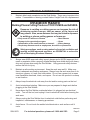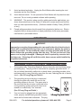
1
DENT REPAIR STUD WELDER
Model 08878
Assembly And Operation Instructions
Due to continuing improvements, actual product may differ slightly from the product described herein.
®
3491 Mission Oaks Blvd., Camarillo, CA 93011
Visit our website at: http://www.harborfreight.com
To prevent serious injury, read and understand
all warnings and instructions before use.
Copyright© 2003, 2007 by Harbor Freight Tools®. All rights reserved. No portion of
this manual or any artwork contained herein may be reproduced in any shape or
form without the express written consent of Harbor Freight Tools.
For technical questions or replacement parts, please call 1-800-444-3353.
Manual revised 02/07
SPECIFICATIONS
Welding Process
Resistance Weld
Power Requirements
120 V, 60 Hz, ~40 A Peak
Circuit Requirement
20 A
Switch
Push Button
Power Cord
14 AWG x 3C / 3 prong grounded plug
Features: High power low heat transformer with resettable safety breaker/ 2 lb.
Slide Hammer, 100 0.078” (2mm) copper studs
SAVE THIS MANUAL
You will need this manual for the safety warnings and precautions, assembly,
operating, inspection, maintenance and cleaning procedures, parts list and assembly
diagram. Keep your invoice with this manual. Write the invoice number on the inside
of the front cover. Keep this manual and invoice in a safe and dry place for future reference.
GENERAL SAFETY RULES
WARNING!
READ AND UNDERSTAND ALL INSTRUCTIONS
Failure to follow all instructions listed below may result in
electric shock, fire, and/or serious injury.
SAVE THESE INSTRUCTIONS
WORK AREA
1.
Keep your work area clean and well lit. Cluttered benches and dark areas invite
accidents.
2.
Do not operate power tools in explosive atmospheres, such as in the presence
of flammable liquids, gases, or dust. Power tools create sparks which may ignite
the dust or fumes.
3.
Keep bystanders, children, and visitors away while operating a power tool. Distractions can cause you to lose control. Protect others in the work area from
debris such as chips and sparks. Provide barriers or shields as needed.
ELECTRICAL SAFETY
1.
Grounded tools must be plugged into an outlet properly installed and grounded
in accordance with all codes and ordinances. Never remove the grounding
prong or modify the plug in any way. Do not use any adapter plugs. Check
REV 03/07
SKU 8878
For technical questions, please call 1-800-444-3353.
Page with a qualified electrician if you are in doubt as to whether the outlet is
properly grounded. If the tools should electrically malfunction or break down,
grounding provides a low resistance path to carry electricity away from the user.
2.
Double insulated tools are equipped with a polarized plug (one blade is wider
than the other). This plug will fit in a polarized outlet only one way. If the
plug does not fit fully in the outlet, reverse the plug. If it still does not fit,
contact a qualified electrician to install a polarized outlet. Do not change
the plug in any way. Double insulation eliminates the need for the three wire
grounded power cord and grounded power supply system.
3.
Avoid body contact with grounded surfaces such as pipes, radiators, ranges, and
refrigerators. There is an increased risk of electric shock if your body is grounded.
4.
Do not expose power tools to rain or wet conditions. Water entering a power tool
will increase the risk of electric shock.
.
Do not abuse the Power Cord. Never use the Power Cord to carry the tools
or pull the Plug from an outlet. Keep the Power Cord away from heat, oil,
sharp edges, or moving parts. Replace damaged Power Cords immediately. Damaged Power Cords increase the risk of electric shock.
6.
When operating a power tool outside, use an outdoor extension cord marked “WA” or “W”. These extension cords are rated for outdoor use, and reduce the risk
of electric shock.
PERSONAL SAFETY
1.
Stay alert. Watch what you are doing, and use common sense when operating a power tool. Do not use a power tool while tired or under the influence
of drugs, alcohol, or medication. A moment of inattention while operating
power tools may result in serious personal injury.
2.
Dress properly. Do not wear loose clothing or jewelry. Contain long hair.
Keep your hair, clothing, and gloves away from moving parts. Loose
clothes, jewelry, or long hair can be caught in moving parts.
3.
Avoid accidental starting. Be sure the Power Switch is off before plugging in.
Carrying power tools with your finger on the Power Switch, or plugging in power
tools with the Power Switch on, invites accidents.
4.
Remove adjusting keys or wrenches before turning the power tool on. A wrench
or a key that is left attached to a rotating part of the power tool may result in personal injury.
.
Do not overreach. Keep proper footing and balance at all times. Proper footing and balance enables better control of the power tool in unexpected situations.
SKU 8878
For technical questions, please call 1-800-444-3353.
Page 6.
Use safety equipment. Always wear eye protection. Dust mask, nonskid safety shoes, hard hat, or hearing protection must be used for appropriate conditions.
TOOL USE AND CARE
1.
Use clamps (not included) or other practical ways to secure and support the
workpiece to a stable platform. Holding the work by hand or against your body is
unstable and may lead to loss of control.
2.
Do not force the tool. Use the correct tool for your application. The correct
tool will do the job better and safer at the rate for which it is designed.
3.
Do not use the power tool if the Power Switch does not turn it on or off. Any tool
that cannot be controlled with the Power Switch is dangerous and must be replaced.
4.
Disconnect the Power Cord Plug from the power source before making any
adjustments, changing accessories, or storing the tool. Such preventive safety
measures reduce the risk of starting the tool accidentally.
.
Store idle tools out of reach of children and other untrained persons. Tools are
dangerous in the hands of untrained users.
6.
Maintain tools with care. Keep cutting tools sharp and clean. Properly maintained tools with a sharp cutting edge are less likely to bind and are easier to
control. Do not use a damaged tool. Tag damaged tools “Do not use” until repaired.
7.
Check for misalignment or binding of moving parts, breakage of parts, and any
other condition that may affect the tool’s operation. If damaged, have the tool
serviced before using. Many accidents are caused by poorly maintained tools.
8.
Use only accessories that are recommended by the manufacturer for your model.
Accessories that may be suitable for one tool may become hazardous when used
on another tool.
SERVICE
1.
Tool service must be performed only by qualified repair personnel. Service or
maintenance performed by unqualified personnel could result in a risk of injury.
2.
When servicing a tool, use only identical replacement parts. Follow instructions in the “Inspection, Maintenance, And Cleaning” section of this manual. Use of unauthorized parts or failure to follow maintenance instructions may
create a risk of electric shock or injury.
SKU 8878
For technical questions, please call 1-800-444-3353.
Page SPECIFIC SAFETY RULES
1.
Maintain labels and nameplates on the Stud Welder. These carry important information. If unreadable or missing, contact Harbor Freight Tools for a replacement.
Inhalation Hazard
Welding/Plasma Cutting Produces toxic fumes and gasses.
Exposure to welding or cutting gasses can increase the risk of
developing certain cancers, such as cancer of the larynx and
lung cancer. Also, some diseases that may be linked to exposure
to welding or plasma cutting gasses or fumes are:
•
•
•
•
Early onset of Parkinson’s Disease
• Heart Disease
Damage to the reproductive organs
• Ulcers
Inflammation of the small intestine or stomach
• Kidney damage
Respiratory diseases such as emphysema, bronchitis or pneumonia
Safety precautions, such as using natural or forced air ventilation and
wearing an ANSI approved respirator, are essential to reduce the
risk of developing the above illnesses.
2.
Always wear ANSI-approved safety impact glasses and a NIOSH-approved dust
mask or respirator under a properly shaded welding face shield along with heavyduty work gloves when using the Stud Welder. Using personal safety devices
reduce the risk for injury.
3.
Maintain a safe working environment. Keep the work area well lit. Make sure
there is adequate surrounding workspace. Always keep the work area free of obstructions, grease, oil, trash, and other debris. Do not use a power tool in areas
near flammable chemicals, dusts, and vapors. Do not use this product in a damp
or wet location.
4.
Always keep the electrical cord away from hot and/or moving parts on the tool.
.
Avoid unintentional starting. Make sure you are prepared to begin work before
plugging in the Stud Welder.
6.
Never leave the Stud Welder unattended when it is plugged into an electrical
outlet. Turn off the tool, and unplug it from its electrical outlet before leaving the
work area.
7.
Always unplug the Stud Welder from its electrical outlet before performing and
inspection, maintenance, or cleaning procedures.
8.
Avoid burns. Do not touch the welded stud electrode or work surface until it
cools.
REV 03/07
SKU 8878
For technical questions, please call 1-800-444-3353.
Page 9.
Avoid accidental activation. Unplug the Stud Welder while inserting the stud
electrode into the Stud Welder.
10.
Avoid electrical shock. Do not operate the Stud Welder with its protective case
removed. Do not touch grounded surfaces while operating
11.
WARNING! This product, when used for welding and similar applications, produces chemicals known to the State of California to cause cancer and birth defects (or other reproductive harm). (California Health & Safety Code § 25249.5,
et seq.)
12.
People with pacemakers should consult their physician(s) before use. Electromagnetic fields in close proximity to heart pacemaker could cause pacemaker
interference or pacemaker failure.
GROUNDING
WARNING!
Improperly connecting the grounding wire can result in the risk of electric shock.
Check with a qualified electrician if you are in doubt as to whether the outlet is
properly grounded. Do not modify the power cord plug provided with the tool.
Never remove the grounding prong from the plug. Do not use the tool if the
power cord or plug is damaged. If damaged, have it repaired by a service facility before use. If the plug will not fit the outlet, have a proper outlet installed by
a qualified electrician.
Grounded Tools: Tools With Three Prong Plugs
1.
Tools marked with “Grounding Required” have a three wire cord and three prong
grounding plug. The plug must be connected to a properly grounded outlet. If
the tool should electrically malfunction or break down, grounding provides a low
resistance path to carry electricity away from the user, reducing the risk of electric
shock. (See 3-Prong Plug and Outlet.)
2.
The grounding prong in the plug is connected
through the green wire inside the cord to the
grounding system in the tool. The green wire in
the cord must be the only wire connected to the
tool’s grounding system and must never be attached to an electrically “live” terminal.
(See 3-Prong Plug and Outlet.)
3.
Your tool must be plugged into an appropriate
outlet, properly installed and grounded in accordance with all codes and ordinances. The plug
SKU 8878
3-Prong Plug and Outlet
For technical questions, please call 1-800-444-3353.
Page and outlet should look like those in the following illustration.
(See 3-Prong Plug and Outlet.)
Extension Cords
1.
Grounded tools require a three wire extension cord. Double Insulated tools can
use either a two or three wire extension cord.
2.
As the distance from the supply outlet increases, you must use a heavier gauge
extension cord. Only use a single 25’ - 50’ 10 gauge cord or a single 25’ or less
12 gauge cord with this tool. Using extension cords with inadequately sized wire
causes a serious drop in voltage, resulting in loss of power and possible tool
damage.
3.
The smaller the gauge number of the wire, the greater the capacity of the cord.
For example, a 10 gauge cord can carry a higher current than a 12 gauge cord.
Do not use extension cords with greater gauge numbers.
4.
Do not use the extension cord for more than one tool.
.
If you are using an extension cord outdoors, make sure it is marked with the suffix “W-A” (“W” in Canada) to indicate it is acceptable for outdoor use.
6.
Make sure your extension cord is properly wired and in good electrical condition.
Always replace a damaged extension cord or have it repaired by a qualified electrician before using it.
7.
Protect your extension cords from sharp objects, excessive heat, and damp or
wet areas.
Symbology
Double Insulated
Canadian Standards Association
Underwriters Laboratories, Inc.
V~
A
Volts Alternating Current
Amperes
No Load Revolutions per Minute
n0 xxxx/min. (RPM)
UNPACKING
When unpacking, check to make sure that the item is intact and undamaged. If
any parts are missing or broken, please call Harbor Freight Tools at the number shown
on the cover of this manual as soon as possible.
SKU 8878
For technical questions, please call 1-800-444-3353.
Page Operation
FIGURE 1
Electrode Assembly (26)
Stud Electrode
(23)
Circuit Breaker
Reset (20)
Trigger (17)
Note: For additional information regarding the parts listed in the following pages, refer
to the Assembly Diagram on page 12.
Caution: Always make sure the power cord to the Stud Welder is unplugged from its
electrical outlet prior to assembling or making any adjustments to the tool.
Note: Before trying to pull a dent out of your own vehicle, it is recommended that you
first practice the procedure on a piece of scrap metal.
Welding the stud
1.
On the location you are going to weld, and in a area as large as the Electrode
Assembly (26) surrounding it, clean the surface down to the metal (no paint).
The entire Electrode Assembly (26) needs to evenly contact the surface without
interference to weld properly.
2.
Insert a Stud (32) into the hole in the Stud Electrode (23). See FIGURE 2.
3.
Plug the Cord (16) into an outlet capable of handling a 20 amp load.
FIGURE 2
Stud (32)
Metal
Surface
SKU 8878
For technical questions, please call 1-800-444-3353.
Page 4.
Holding the Stud Welder firmly with both hands and using a well-balanced
stance, firmly push the Stud (32) against
FIGURE 3
the metal surface until the Electrode
Electrode
Assembly (26) is flush with the metal
Assembly (26)
surface. See FIGURE 3.
.
With the Electrode Assembly (26)
perfectly square to the surface,
hold the Stud Welder very steady and
squeeze the Trigger (17) for only 1/2 to
1 second. Immediately release the Trigger (17) after 1/2 to 1 seconds.
Metal
Surface
Note: It is normal for approximately 1/4” of
discoloration to show around the weld. If you hold the trigger down more than 1
second, the metal skin of the vehicle will burn.
Note: If the Stud Welder remains on too long (Approximately 6 seconds) the circuit
breaker will shut the unit down to protect it. To reset the Breaker, allow the unit to
cool down and then push the Circuit Breaker Reset (20).
6.
Pull the Stud Welder directly back, leaving the Stud (32) in place. You will notice
the tip of the stud remains exposed.
7.
When done with the Stud Welder, unplug the tool and store it safely.
Pulling out the Dent
FIGURE 4 - Slide Hammer (31)
Metal
Surface
Roller
Center Handle
Back
Handle
1.
Slip the end roller of the Slide Hammer (31) over the Stud (32) and tighten it on
the exposed tip of the stud by holding the Back Handle and turning the Roller
counterclockwise. See FIGURE 4.
2.
With one hand on the Center Handle and one on the Back Handle, apply a backward hammering motion, hammering the Center Handle against the Back Handle
(away from the metal surface) until the dent has popped out. See FIGURE 4.
3.
To disengage the Slide Hammer (31) from the Stud (32), gently tap the Center
Handle forward against the Roller until the Stud (32) is released.
4.
Cut the Stud off and grind it down so it is flush with the metal surface.
REV 03/07
SKU 8878
For technical questions, please call 1-800-444-3353.
Page INSPECTION, MAINTENANCE, AND CLEANING
1.
WARNING! Make sure the tool is unplugged from its electrical outlet before
performing any inspection, maintenance, or cleaning procedures.
2.
BEFORE EACH USE, inspect the general condition of the Stud Welder. Check
for loose screws, misalignment or binding of moving parts, cracked or broken
parts, damaged electrical wiring, and any other condition that may affect its safe
operation. If abnormal noise or vibration occurs, have the problem corrected
before further use.
Do not use damaged equipment.
3.
Periodically inspect the power cord for cracks. Replace if necessary.
4.
Clean the unit using a damp cloth. Never use solvents.
.
Keep the Electrode Assembly (26) free of oxidation by cleaning with fine steel
wool.
6.
If necessary, use a fine metal file to keep the electrode flat and clean.
TROUBLESHOOTING
Problem
Cause
Stud does not Weld, weld Area
is Cold
1. Insufficient/no contact to
metal surface with Electrode
Assembly
2. No power to line cord
3. Stud Welder Circuit Breaker
Open
Weak weld, stud does not hold
1. “On Time” Not long enough.
2. Electrode or Stud dirty
3. Weld surface not cleaned
down to bare metal
1. Weld time is too long
2. Using incorrect Stud
Weld is burning through metal
Circuit breaker continues to trip
SKU 8878
Solution
1. Clean metal surface for the
entire Electrode Assembly
(26) to contact fully, press
harder, and ensure Electrode
Assembly (26) contacts the
surface evenly
2. Check Power Source
3. Press Circuit Breaker Reset
1. Hold trigger longer
2. Clean or replace both
3. Clean surface to the metal
1. Shorten weld time
2. Replace the Stud with the
correct size and clean the
electrode
1. Circuit rating not large enough 1. Connect to 20 A dedicated
circuit
2. Electrical fault in Welder
2. Have qualified technician
service welder
For technical questions, please call 1-800-444-3353.
Page 10
PARTS LIST
Part
1
2
3
4
5
6
7
8
9
10
11
12
13
14
15
16
Description
Insulator Sleeve
Nut
Washer
Nut
Split Lock Washer
Braided Strap
Screw
Case (right)
Washer
Screw
Transformer
Insulator
Nut
Case (left)
Label
Cord
Q’ty
1
2
2
2
2
1
6
1
4
1
1
1
8
1
1
1
Part
17
18
19
20
21
22
23
24
25
26
27
28
29
30
31
32
Description
Trigger
Trigger Boot
Screw
Circuit Breaker Reset
Insulator F.R.P.
Screw
Stud Electrode
Sliding Electrode
Spring
Electrode Assembly
Wire Assembly
Wire Assembly
Terminal
Split Washer
Slide Hammer
2mm Studs (100/Bag)
Q’ty
1
1
2
1
1
1
1
1
1
1
1
1
1
1
1
1
ASSEMBLY DIAGRAM
SKU 8878
For technical questions, please call 1-800-444-3353.
Page 11
PLEASE READ THE FOLLOWING CAREFULLY
The manufacturer and/or distributor has provided the parts list and assembly diagram in this manual as a reference tool only. Neither the manufacturer
or distributor makes any representation or warranty of any kind to the buyer
that he or she is qualified to make any repairs to the product, or that he or
she is qualified to replace any parts of the product. In fact, the manufacturer
and/or distributor expressly states that all repairs and parts replacements
should be undertaken by certified and licensed technicians, and not by the
buyer. The buyer assumes all risk and liability arising out of his or her repairs
to the original product or replacement parts thereto, or arising out of his
or her installation of replacement parts thereto.
Record Product’s Serial Number Here:
Note: If product has no serial number, record month and year of purchase instead.
Note: Some parts are listed and shown for illustration purposes only, and are not available individually as replacement parts.
Limited 1 Year / 90 day warranty
Harbor Freight Tools Co. makes every effort to assure that its products meet high quality
and durability standards, and warrants to the original purchaser that for a period of ninety days
from date of purchase that the torch, liner, wire feed mechanism (if applicable), welding clamps,
electrode holders, cables and accessories packed with the welder are free of defects in materials and workmanship. This Limited 90 Day/1 Year Warranty shall not apply to consumable
parts such as tips, welding wire, and gas nozzles. Harbor Freight Tools also warrants to
the original purchaser, for a period of one year from date of purchase, that the transformer and
rectifier are free from defects in materials and workmanship (90 days if used by a professional
contractor or if used as rental equipment). This warranty does not apply to damage due directly
or indirectly to misuse, abuse, negligence or accidents, repairs or alterations outside our facilities, normal wear and tear, or to lack of maintenance. We shall in no event be liable for death,
injuries to persons or property, or for incidental, contingent, special or consequential damages
arising from the use of our product. Some states do not allow the exclusion or limitation of
incidental or consequential damages, so the above limitation of exclusion may not apply to you.
This warranty is expressly in lieu of all other warranties, express or
implied, including the warranties of merchantability and fitness.
To take advantage of this warranty, the product or part must be returned to us with transportation charges prepaid. Proof of purchase date and an explanation of the complaint must
accompany the merchandise. If our inspection verifies the defect, we will either repair or replace
the product at our election or we may elect to refund the purchase price if we cannot readily and
quickly provide you with a replacement. We will return repaired products at our expense, but if
we determine there is no defect, or that the defect resulted from causes not within the scope of
our warranty, then you must bear the cost of returning the product.
This warranty gives you specific legal rights and you may also have other rights which
vary from state to state.
3491 Mission Oaks Blvd. • PO Box 6009 • Camarillo, CA 93011 • (800) 444-3353
REV 07k
SKU 8878
For technical questions, please call 1-800-444-3353.
Page 12