1
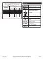
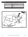
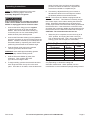
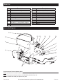
1. Work area safety
Save This Manual
Keep this manual for the safety warnings and
precautions, assembly, operating, inspection,
maintenance and cleaning procedures. Write the
product’s serial number in the back of the manual near
the assembly diagram (or month and year of purchase
if product has no number). Keep this manual and the
receipt in a safe and dry place for future reference.
IMPORTANT SAFETY
INFORMATION
In this manual, on the labeling, and all other
information provided with this product:
This is the safety alert symbol. It is
used to alert you to potential personal
injury hazards. Obey all safety
messages that follow this symbol
to avoid possible injury or death.
a.Keep work area clean and well lit. Cluttered or
dark areas invite accidents.
b.Do not operate welders in explosive
atmospheres, such as in the presence of
flammable liquids, gases or dust. Welders
create sparks which may ignite the dust or fumes.
c.Keep children and bystanders away while
operating a welder. Distractions can cause you to
lose control.
2. Electrical safety
a.Welder plugs must match the outlet.
Never modify the plug in any way. Do not use
any adapter plugs with grounded welders.
Unmodified plugs and matching outlets will reduce
risk of electric shock.
b.Avoid body contact with grounded surfaces
such as pipes, radiators, ranges and
refrigerators. There is an increased risk of electric
shock if your body is grounded.
c.Do not expose welders to rain or wet
conditions. Water entering a welder will increase
the risk of electric shock.
DANGER indicates a hazardous situation which, if
not avoided, will result in death or serious injury.
d.Do not abuse the cord. Never use the cord
for carrying, pulling or unplugging the welder.
Keep cord away from heat, oil, sharp edges
or moving parts. Damaged or entangled cords
increase the risk of electric shock.
WARNING indicates a hazardous situation which, if
not avoided, could result in death or serious injury.
e.When operating a welder outdoors, use an
extension cord suitable for outdoor use.
Use of a cord suitable for outdoor use reduces the
risk of electric shock.
CAUTION, used with the safety alert symbol,
indicates a hazardous situation which, if not
avoided, could result in minor or moderate injury.
f. If operating a welder in a damp location is
unavoidable, use a Ground Fault Circuit
Interrupter (GFCI) protected supply. Use of a
GFCI reduces the risk of electric shock.
NOTICE is used to address practices
not related to personal injury.
CAUTION, without the safety alert symbol, is used
to address practices not related to personal injury.
General Safety Warnings
WARNING Read all safety warnings and
instructions. Failure to follow the warnings and
instructions may result in electric shock, fire and/
or serious injury.
Save all warnings and instructions
for future reference.
Page 2
For technical questions, please call 1-888-866-5797.
Item 61749
3. Personal safety
4. Welder use and care
a.Stay alert, watch what you are doing and use
common sense when operating a welder.
Do not use a welder while you are tired or under
the influence of drugs, alcohol or medication.
A moment of inattention while operating welders
may result in serious personal injury.
b.Use safety equipment. Always wear
ANSI‑approved safety glasses and arc shaded,
impact safety full face shield. Safety equipment
such as NIOSH-approved respirator, heavy-duty
work gloves, non-skid safety shoes, or hearing
protection used for appropriate conditions will
reduce personal injuries.
c.Prevent unintentional starting. Ensure the
switch is in the off-position before connecting
to power source or moving the welder. Carrying
or energizing welders that have the switch on
invites accidents.
d.Do not overreach. Keep proper footing and
balance at all times. This enables better control
of the welder in unexpected situations.
e.Only use safety equipment that has been
approved by an appropriate standards agency.
Unapproved safety equipment may not provide
adequate protection. Eye protection must be ANSIapproved and breathing protection must be NIOSHapproved for the specific hazards in the work area.
a.Do not use the welder if the switch does not
turn it on and off. Any welder that cannot be
controlled with the switch is dangerous and must
be repaired.
b.Disconnect the plug from the power source
before making any adjustments, changing
accessories, or storing welders. Such
preventive safety measures reduce the risk of
starting the welder accidentally.
c.Store idle welders out of the reach of children
and do not allow persons unfamiliar with the
welder or these instructions to operate the
welder. Welders are dangerous in the hands of
untrained users.
d.Maintain welders. Check for misalignment or
binding of moving parts, breakage of parts and
any other condition that may affect the welder’s
operation. If damaged, have the welder
repaired before use. Many accidents are caused
by poorly maintained welders.
e.Use the welder and accessories in accordance
with these instructions, taking into account
the working conditions and the work to be
performed. Use of the welder for operations
different from those intended could result in a
hazardous situation.
5. Service
a.Have your welder serviced by a qualified repair
person using only identical replacement parts.
This will ensure that the safety of the welder is
maintained.
Item 61749
For technical questions, please call 1-888-866-5797.
Page 3
Welder Safety Warnings
1. Maintain labels and nameplates on the
Welder. These carry important information.
If unreadable or missing, contact Harbor
Freight Tools for a replacement.
2. Maintain a safe working environment. Keep
the work area well lit. Make sure there is
adequate surrounding workspace. Always
keep the work area free of obstructions,
grease, oil, trash, and other debris.
7.
Prevent accidental fires.
Remove any combustible material
from the work area.
• When possible, move the work to a location well
away from combustible materials. If relocation
is not possible, protect the combustibles with
a cover made of fire resistant material.
3. Avoid unintentional starting. Make sure you are
prepared to begin work before turning on the Welder.
• Remove or make safe all combustible
materials for a radius of 35 feet (10 meters)
around the work area. Use a fire resistant
material to cover or block all open doorways,
windows, cracks, and other openings.
4. Unplug before performing maintenance. Unplug
the Welder from its electrical outlet before performing
any inspection, maintenance, or cleaning procedures.
• Enclose the work area with portable fire
resistant screens. Protect combustible
walls, ceilings, floors, etc., from sparks
and heat with fire resistant covers.
5. Never leave the Welder unattended
while energized. Turn power off if
you have to leave the Welder.
Prevent eye injury and burns.
Wearing and using ANSI-approved
personal safety clothing and safety
devices reduce the risk for injury.
6.
• If working on a metal wall, ceiling, etc.,
prevent ignition of combustibles on the other
side by moving the combustibles to a safe
location. If relocation of combustibles is not
possible, designate someone to serve as a
fire watch, equipped with a fire extinguisher,
during the cutting process and for at least one
half hour after the cutting is completed.
• Wear ANSI-approved safety impact eye
goggles underneath welding eye protection
featuring at least a number 10 shade lens
rating, such as the one included.
• Do not weld or cut on materials having a
combustible coating or combustible internal
structure, as in walls or ceilings, without an
approved method for eliminating the hazard.
• Leather leggings, fire resistant shoes or
boots should be worn when using this
product. Do not wear pants with cuffs, shirts
with open pockets, or any clothing that can
catch and hold molten metal or sparks.
• Do not dispose of hot slag in containers
holding combustible materials. Keep a fire
extinguisher nearby and know how to use it.
• Keep clothing free of grease, oil, solvents,
or any flammable substances. Wear dry,
insulating gloves and protective clothing.
• Wear an approved head covering to protect
the head and neck. Use aprons, cape, sleeves,
shoulder covers, and bibs designed and
approved for welding and cutting procedures.
• When welding/cutting overhead or in confined
spaces, wear flame resistant ear plugs or
ear muffs to keep sparks out of ears.
Page 4
• After spot welding, make a thorough examination
for evidence of fire. Be aware that easily visible
smoke or flame may not be present for some
time after the fire has started. Do not weld or
cut in atmospheres containing dangerously
reactive or flammable gases, vapors, liquids,
and dust. Provide adequate ventilation in work
areas to prevent accumulation of flammable
gases, vapors, and dust. Do not apply heat to a
container that has held an unknown substance
or a combustible material whose contents, when
heated, can produce flammable or explosive
vapors. Clean and purge containers before
applying heat. Vent closed containers, including
castings, before preheating, welding, or cutting.
For technical questions, please call 1-888-866-5797.
Item 61749
8. Avoid overexposure to fumes and gases.
Always keep your head out of the fumes. Do
not breathe the fumes. Use enough ventilation
or exhaust, or both, to keep fumes and gases
from your breathing zone and general area.
• Where ventilation is questionable, have a
qualified technician take an air sampling to
determine the need for corrective measures.
Use mechanical ventilation to improve air
quality. If engineering controls are not
feasible, use an approved respirator.
• Work in a confined area only if it is well-ventilated,
or while wearing an air-supplied respirator.
• Follow OSHA guidelines for Permissible Exposure
Limits (PEL’s) for various fumes and gases.
• Follow the American Conference of
Governmental Industrial Hygienists
recommendations for Threshold Limit
Values (TLV’s) for fumes and gases.
• Have a recognized specialist in Industrial Hygiene
or Environmental Services check the operation
and air quality and make recommendations
for the specific welding or cutting situation.
9.
INHALATION HAZARD:
Welding and Plasma Cutting
Produce TOXIC FUMES.
Exposure to welding or cutting exhaust
fumes can increase the risk of
developing certain cancers, such as
cancer of the larynx and lung cancer.
Also, some diseases that may be linked
to exposure to welding or plasma
cutting exhaust fumes are:
• Early onset of Parkinson’s Disease
•Heart disease •Ulcers
• Damage to the reproductive organs
• Inflammation of the small intestine or stomach
• Kidney damage
• Respiratory diseases such as emphysema,
bronchitis, or pneumonia
Use natural or forced air ventilation and wear
a respirator approved by NIOSH to protect
against the fumes produced to reduce the
risk of developing the above illnesses.
Item 61749
10. Do not touch live electrical parts.
Wear dry, insulating gloves. Do not touch
Electrode or Electrode Clamp with bare hand.
Do not wear wet or damaged gloves.
11. Protect yourself from electric shock. Do not
use outdoors. Insulate yourself from the
workpiece and ground. Use nonflammable,
dry insulating material if possible, or use dry
rubber mats, dry wood or plywood, or other dry
insulating material big enough to cover your
full area of contact with the work or ground.
12. People with pacemakers should consult
their physician(s) before using this product.
Electromagnetic fields in close proximity to
a heart pacemaker could cause interference
to, or failure of the pacemaker.
13. Use care not to touch the welding tip to
grounded material whenever the unit is
plugged in. Electric shock, fire, or burns may
happen if appropriate precautions are not taken.
14. Ensure that the unit is placed on a stable location
before use. If this unit falls while plugged in,
severe injury, electric shock, or fire may result.
15. This product, when used for welding and similar
applications, contains or produces a chemical
known to the State of California to cause cancer
and birth defects (or other reproductive harm).
(California Health & Safety Code § 25249.5, et seq.)
16. Handling the cord on this product will expose you to
lead, a chemical known to the State of California to
cause cancer, and birth defects or other reproductive
harm. Wash hands after handling. (California
Health & Safety Code § 25249.5, et seq.)
17. The warnings, precautions, and instructions
discussed in this instruction manual cannot
cover all possible conditions and situations
that may occur. It must be understood by the
operator that common sense and caution are
factors which cannot be built into this product,
but must be supplied by the operator.
SAVE THESE
INSTRUCTIONS.
For technical questions, please call 1-888-866-5797.
Page 5
Extension Cords
Grounding
1. Grounded tools require a three wire extension cord.
Double Insulated tools can use either
a two or three wire extension cord.
TO PREVENT ELECTRIC SHOCK AND
DEATH FROM INCORRECT GROUNDING
WIRE CONNECTION:
Check with a qualified electrician if you are
in doubt as to whether the outlet is properly
grounded. Do not modify the power cord plug
provided with the tool. Never remove the grounding
prong from the plug. Do not use the tool if the power
cord or plug is damaged. If damaged, have it
repaired by a service facility before use. If the plug
will not fit the outlet, have a proper outlet installed by
a qualified electrician.
Grounded Tools:
Tools with Three Prong Plugs
2. As the distance from the supply outlet increases,
you must use a heavier gauge extension cord.
Using extension cords with inadequately sized wire
causes a serious drop in voltage, resulting in loss of
power and possible tool damage. (See Table A.)
3. The smaller the gauge number of the wire, the
greater the capacity of the cord. For example,
a 14 gauge cord can carry a higher current
than a 16 gauge cord. (See Table A.)
4. When using more than one extension cord to make
up the total length, make sure each cord contains at
least the minimum wire size required. (See Table A.)
5. If you are using one extension cord for more
than one tool, add the nameplate amperes
and use the sum to determine the required
minimum cord size. (See Table A.)
6. If you are using an extension cord outdoors, make
sure it is marked with the suffix “W-A” (“W” in
Canada) to indicate it is acceptable for outdoor use.
7. Make sure the extension cord is properly wired
and in good electrical condition. Always replace
a damaged extension cord or have it repaired
by a qualified electrician before using it.
1. Tools marked with “Grounding Required” have a three
wire cord and three prong grounding plug. The plug
must be connected to a properly grounded outlet.
If the tool should electrically malfunction or break
down, grounding provides a low resistance path to
carry electricity away from the user, reducing the risk
of electric shock. (See 3-Prong Plug and Outlet.)
8. Protect the extension cords from sharp objects,
excessive heat, and damp or wet areas.
2. The grounding prong in the plug is connected through
the green wire inside the cord to the grounding
system in the tool. The green wire in the cord must
be the only wire connected to the tool’s grounding
system and must never be attached to an electrically
“live” terminal. (See 3-Prong Plug and Outlet.)
3. The tool must be plugged into an appropriate outlet,
properly installed and grounded in accordance
with all codes and ordinances. The plug and
outlet should look like those in the preceding
illustration. (See 3-Prong Plug and Outlet.)
Page 6
For technical questions, please call 1-888-866-5797.
Item 61749
Table A: RECOMMENDED MINIMUM
WIRE GAUGE FOR EXTENSION
CORDS* (120/240 VOLT)
EXTENSION CORD
NAMEPLATE
LENGTH
AMPERES
(at full load)
25′ 50′ 75′ 100′ 150′
0 – 2.0
18
18
18
18
16
2.1 – 3.4
18
18
18
16
14
3.5 – 5.0
18
18
16
14
12
5.1 – 7.0
18
16
14
12
12
7.1 – 12.0
18
14
12
10
-
12.1 – 16.0
14
12
10
-
-
16.1 – 20.0
12
10
-
-
-
* Based on limiting the line voltage drop to five volts at
150% of the rated amperes.
Item 61749
Symbology
Workpiece Ground Cable
Electrode Cable
Overheat Shutdown Indicator
Cooling Fan
Housing Ground Point
V~
A
OCV
KVA
AWG
Volts Alternating Current
Amperes
Open Circuit Voltage
Kilovolt Amperes
(Volts / 1000 * Amperes)
American Wire Gauge
For technical questions, please call 1-888-866-5797.
Page 7
Specifications
Electrical Input
Electrode Sizes
Duty Cycles
Electrode Cable
Ground Clamp Cable
Welding Capacity
120 VAC / 60 Hz / 1 Phase / 20 A
Thermal Overload Protection
1/16" – 3/32" (1.6 mm) – (2.5 mm)
35% @ 75 A
60% @ 65 A
100% @ 50 A
7 Gauge x 5'-6" Long
7 Gauge x 5' Long
Up to 6 Gauge Steel
KNOB (5)
OVERLOAD PROTECTION LIGHT (2)
ELECTRODE
(NOT INCLUDED)
ELECTRODE
HOLDER
(6)
QUICK PLUG
(8)
QUICK CONNECTOR (9)
WORK PIECE
Page 8
GROUND CLAMP (7)
For technical questions, please call 1-888-866-5797.
Figure A
Item 61749
along the work piece and down as the welding
process consumes the electrode. Replace the
electrode as needed to complete the job.
Operating Instructions
NOTE: For additional references to the parts
listed in the following pages, refer to the
Assembly Diagram and Figure A.
Prior to performing any assembly procedures,
make sure the Power Cord of the Inverter Arc
Welder is unplugged from its electrical outlet.
1. Connect the Quick Plug (8) to the negative
(-) Quick Connector (9) on the Inverter Arc
Welder. Also connect the Ground Clamp (7)
to the work piece or to a metal welding table
where the work piece will be placed.
2. Connect the Electrode Holder (6) to the positive
(+) Quick Connector on the front of the Inverter Arc
Welder. Install an electrode (not included) into the
Electrode Holder by squeezing the Holder while
positioning the electrode at the desired angle.
3. Plug the Power Cord (16) into the nearest
120 volt, grounded, electrical outlet.
WARNING! Wear ANSI-approved safety glasses
under a properly shaded welding helmet.
4. Hold the Electrode Holder (6) away from
all objects. Then, position the Knob
(5) to about mid-range to start.
5. To begin welding, position the electrode at about
a 60º angle and touch the tip of it to the work
piece. Once the arc is stable, move the electrode
Item 61749
6. If necessary, adjust the Knob (5) to increase or
decrease the electrical current output to achieve
the desired performance and weld results.
NOTE: The Inverter Arc Welder is equipped with an
automatic “Hot Start”. This feature momentarily surges
the current output, which makes starting the electrode
easier. Should the electrode stick to the work piece,
usually a quick twist of the Electrode Holder (6) will break
the electrode free. If the electrode is not broken loose,
shut down the Inverter Arc Welder and physically remove
the electrode from the Electrode Holder and work piece.
CAUTION! The electrode and metal are hot.
7. When the job is completed, turn the Knob (5) to its
“OFF” position, and unplug the Power Cord (16)
from its electrical outlet. Then, remove the Ground
Clamp (7) from the work piece or metal table.
Table B: Electrode Size and Amp Chart
Electrode Diameter
Amp
Plate
(Thickness)
Range
1/16"
3/32"
1/8
5/32"
3/16"
1/4"
5/16"
20 - 40
40 - 125
75 - 185
105 - 250
140 - 305
210 - 430
275 - 450
up to 3/16"
up to 1/4"
over 1/8"
over 1/4"
over 3/8"
over 3/8"
over 1/2"
Ratings listed above are estimates and will
vary depending on electrode coating and
electrode manufacturer. When possible, use the
manufacturer’s recommended amperage setting instead.
For technical questions, please call 1-888-866-5797.
Page 9
Inspection, Maintenance, and Cleaning
them and wait for the Welder to cool while
observing the Overload Protection Light (2).
4. The current output is unstable and unable
to produce a smooth welding bead.
Make sure the Knob (5) is in its “OFF” position.
Unplug the Power Cord (16) from its electrical outlet,
and allow the Inverter Arc Welder and discharge
electrode to completely cool before performing any
inspection, maintenance, or cleaning procedures.
1. Before each use, inspect the general condition of the
Inverter Arc Welder. Check for damaged electrical
wiring, loose connections, cracked, burnt, or broken
parts, and any other condition that may affect its safe
operation. If abnormal noise or vibration occurs,
have the problem corrected before further use.
Do not use damaged equipment.
2. Before each use, clean or, if necessary,
replace the electrode.
3. To clean, use a shop vacuum cleaner,
or use compressed air.
4. When storing, make sure to store the Inverter
Arc Welder in a safe, clean, and dry location.
TROUBLESHOOTING GUIDE
1. The Inverter Arc Welder will not turn on.
a. Make sure the Power Cord (16) is plugged in.
b. Make sure the Quick Plugs (8) are properly
plugged into the Quick Connectors (9).
2. The Inverter Arc Welder is turned
on, but will not strike an arc.
a. Make sure the electrode is securely
attached to the Electrode Holder (6).
b. Make sure the Quick Plugs (8) are properly
plugged into the Quick Connectors (9).
c. Make sure the Ground Clamp (7) is securely
attached to the work piece or metal table on which
the work piece is placed, and that the point of
attachment is clean from rust, paint, or any other
material that would insulate the connection.
a. Make sure the Power Cord (16) is properly
connected to its electrical outlet.
b. Make sure the Quick Plugs (8) are securely
connected to the Quick Connectors (9).
c. Make sure the Ground Clamp (7) is securely
attached to the work piece or metal table on which
the work piece is placed, and that the point of
attachment is clean from rust, paint, or any other
material that would insulate the connection.
d. Make sure the electrode is in good condition,
and that the welding current output is
properly adjusted. (Increasing the current
output usually improves this situation.)
PLEASE READ THE
FOLLOWING CAREFULLY
THE MANUFACTURER AND/OR DISTRIBUTOR
HAS PROVIDED THE PARTS LIST AND
ASSEMBLY DIAGRAM IN THIS MANUAL AS
A REFERENCE TOOL ONLY. NEITHER THE
MANUFACTURER OR DISTRIBUTOR MAKES
ANY REPRESENTATION OR WARRANTY
OF ANY KIND TO THE BUYER THAT HE OR
SHE IS QUALIFIED TO MAKE ANY REPAIRS
TO THE PRODUCT, OR THAT HE OR SHE IS
QUALIFIED TO REPLACE ANY PARTS OF THE
PRODUCT. IN FACT, THE MANUFACTURER AND/
OR DISTRIBUTOR EXPRESSLY STATES THAT
ALL REPAIRS AND PARTS REPLACEMENTS
SHOULD BE UNDERTAKEN BY CERTIFIED
AND LICENSED TECHNICIANS, AND NOT
BY THE BUYER. THE BUYER ASSUMES ALL
RISK AND LIABILITY ARISING OUT OF HIS OR
HER REPAIRS TO THE ORIGINAL PRODUCT
OR REPLACEMENT PARTS THERETO, OR
ARISING OUT OF HIS OR HER INSTALLATION
OF REPLACEMENT PARTS THERETO.
3. The Inverter Arc Welder is not working, and
the Overload Protection Light (2) is on.
a. When the Inverter Arc Welder overheats
it will automatically shut down temporarily.
When this happens stop welding, but
leave the Welder on until it cools down.
As soon as the Overload Protection Light
goes off you may continue welding.
b. If the Welder does not cool down as described
above, check to see if the Fan (13) is operating.
If the Fan is operating, check the side panel
vents to see if anything is obstructing airflow
from the Fan. If obstructions exist, remove
Page 10
For technical questions, please call 1-888-866-5797.
Item 61749
Parts List
Part
1
2
3
4
5
6
7
8
9
10
11
12
13
Description
Part
Potentiometer
Overload Protection Light
PCB
Nut (M6), Washer
Knob
Electrode Holder
Ground Clamp
Quick Plug
Quick Connector
Steel Base
Screw (M8), Washer, Spring Washer
Nut (M14 x 1), Fitting Washer, Support
Plastic Tube
Fan
14
15
16
17
18
19
20
21
22
23
24
25
26
Description
Cable Fixture
Tapping Screw (M4 x 20)
Power Cord
Tapping Screw (4.8 x 9mm)
Earth Rivet
Tapping Screw (4.2 x 9mm)
Steel Cover
Belt
Buzzer Control Board
Radiator
Transformer
Capacitor
Radiator
Assembly Diagram
21
22
20
23
19
24
25
26
1
2
15
18
16
14
3
17
13
5
4
10
6
12
7
9
8
11
Record Product’s Serial Number Here:
Note: If product has no serial number, record month and year of purchase instead.
Note: Some parts are listed and shown for illustration purposes only, and
are not available individually as replacement parts.
Item 61749
For technical questions, please call 1-888-866-5797.
Page 11
Limited 90 Day Warranty
Harbor Freight Tools Co. makes every effort to assure that its products meet high quality and durability standards,
and warrants to the original purchaser that this product is free from defects in materials and workmanship for the
period of 90 days from the date of purchase. This warranty does not apply to damage due directly or indirectly,
to misuse, abuse, negligence or accidents, repairs or alterations outside our facilities, criminal activity, improper
installation, normal wear and tear, or to lack of maintenance. We shall in no event be liable for death, injuries
to persons or property, or for incidental, contingent, special or consequential damages arising from the use of
our product. Some states do not allow the exclusion or limitation of incidental or consequential damages, so the
above limitation of exclusion may not apply to you. THIS WARRANTY IS EXPRESSLY IN LIEU OF ALL OTHER
WARRANTIES, EXPRESS OR IMPLIED, INCLUDING THE WARRANTIES OF MERCHANTABILITY AND FITNESS.
To take advantage of this warranty, the product or part must be returned to us with transportation charges
prepaid. Proof of purchase date and an explanation of the complaint must accompany the merchandise.
If our inspection verifies the defect, we will either repair or replace the product at our election or we may
elect to refund the purchase price if we cannot readily and quickly provide you with a replacement. We will
return repaired products at our expense, but if we determine there is no defect, or that the defect resulted
from causes not within the scope of our warranty, then you must bear the cost of returning the product.
This warranty gives you specific legal rights and you may also have other rights which vary from state to state.
3491 Mission Oaks Blvd. • PO Box 6009 • Camarillo, CA 93011 • 1-888-866-5797