1
FCC INFORMATION (U.S.A.)
1. IMPORTANT NOTICE: DO NOT MODIFY
THIS UNIT!
This product, when installed as indicated in the
instructions contained in this manual, meets FCC
requirements. Modifications not expressly approved
by Yamaha may void your authority, granted by the
FCC, to use the product.
2. IMPORTANT: When connecting this product to
accessories and/or another product use only high
quality shielded cables. Cable/s supplied with this
product MUST be used. Follow all installation instructions. Failure to follow instructions could void
your FCC authorization to use this product in the
USA.
3. NOTE: This product has been tested and found to
comply with the requirements listed in FCC Regulations, Part 15 for Class “B” digital devices. Compliance with these requirements provides a reasonable
level of assurance that your use of this product in a
residential environment will not result in harmful
interference with other electronic devices. This
equipment generates/uses radio frequencies and, if
not installed and used according to the instructions
found in the users manual, may cause interference
harmful to the operation of other electronic devices.
Compliance with FCC regulations does not guaran-
tee that interference will not occur in all installations.
If this product is found to be the source of interference, which can be determined by turning the unit
“OFF” and “ON”, please try to eliminate the problem
by using one of the following measures:
Relocate either this product or the device that is
being affected by the interference.
Utilize power outlets that are on different branch
(circuit breaker or fuse) circuits or install AC line
filter/s.
In the case of radio or TV interference, relocate/
reorient the antenna. If the antenna lead-in is 300
ohm ribbon lead, change the lead-in to co-axial type
cable.
If these corrective measures do not produce satisfactory results, please contact the local retailer authorized to distribute this type of product. If you can
not locate the appropriate retailer, please contact
Yamaha Corporation of America, Electronic Service
Division, 6600 Orangethorpe Ave, Buena Park,
CA90620
The above statements apply ONLY to those products distributed by Yamaha Corporation of America
or its subsidiaries.
* This applies only to products distributed by YAMAHA CORPORATION OF AMERICA.
NEDERLAND / NETHERLAND
• Dit apparaat bevat een lithium batterij voor geheugen back-up.
• This apparatus contains a lithium battery for memory back-up.
• Raadpleeg uw leverancier over de verwijdering van de batterij op
het moment dat u het apparaat ann het einde van de levensduur
afdankt of de volgende Yamaha Service Afdeiing:
Yamaha Music Nederland Service Afdeiing
Kanaalweg 18-G, 3526 KL UTRECHT
Tel. 030-2828425
• For the removal of the battery at the moment of the disposal at the
end of the service life please consult your retailer or Yamaha
Service Center as follows:
Yamaha Music Nederland Service Center
Address : Kanaalweg 18-G, 3526 KL UTRECHT
Tel
: 030-2828425
• Gooi de batterij niet weg, maar lever hem in als KCA.
• Do not throw away the battery. Instead, hand it in as small chemical
waste.
ADVARSEL!
Lithiumbatteri—Eksplosionsfare ved fejlagtig håndtering.
Udskiftning må kun ske med batteri af samme fabrikat og
type. Levér det brugte batteri tilbage til leverandoren.
VARNING
Explosionsfara vid felaktigt batteribyte. Använd samma
batterityp eller en ekvivalent typ som rekommenderas av
apparattillverkaren. Kassera använt batteri enlight
fabrikantens instruktion.
VAROITUS
Paristo voi räjähtää, jos se on virheellisesti asennettu. Vaihda
paristo ainoastaan laitevalmistajan suosittelemaan tyyppiin.
Hävitä käytetty paristo valmistajan ohjeiden mukaisesti.
SPECIAL MESSAGE SECTION
This product utilizes batteries or an external power supply
(adapter). DO NOT connect this product to any power
supply or adapter other than one described in the manual,
on the name plate, or specifically recommended by
Yamaha.
WARNING: Do not place this product in a position where
anyone could walk on, trip over ,or roll anything over power
or connecting cords of any kind. The use of an extension
cord is not recommended! IF you must use an extension
cord, the minimum wire size for a 25' cord (or less ) is 18
AWG. NOTE: The smaller the AWG number ,the larger the
current handling capacity. For longer extension cords,
consult a local electrician.
This product should be used only with the components
supplied or; a cart, rack, or stand that is recommended by
Yamaha. If a cart, etc., is used, please observe all safety
markings and instructions that accompany the accessory
product.
SPECIFICATIONS SUBJECT TO CHANGE:
The information contained in this manual is believed to be
correct at the time of printing. However, Yamaha reserves
the right to change or modify any of the specifications
without notice or obligation to update existing units.
This product, either alone or in combination with an amplifier and headphones or speaker/s, may be capable of
producing sound levels that could cause permanent hearing loss. DO NOT operate for long periods of time at a
high volume level or at a level that is uncomfortable. If you
experience any hearing loss or ringing in the ears, you
should consult an audiologist.
IMPORTANT: The louder the sound, the shorter the time
period before damage occurs.
Some Yamaha products may have benches and / or
accessory mounting fixtures that are either supplied with the
product or as optional accessories. Some of these items
are designed to be dealer assembled or installed. Please
make sure that benches are stable and any optional fixtures
(where applicable) are well secured BEFORE using.
Benches supplied by Yamaha are designed for seating only.
No other uses are recommended.
NOTICE:
This product MAY contain a small non-rechargeable battery which (if applicable) is soldered in place. The average
life span of this type of battery is approximately five years.
When replacement becomes necessary, contact a qualified service representative to perform the replacement.
This product may also use “household” type batteries.
Some of these may be rechargeable. Make sure that the
battery being charged is a rechargeable type and that the
charger is intended for the battery being charged.
When installing batteries, do not mix batteries with new, or
with batteries of a different type. Batteries MUST be installed correctly. Mismatches or incorrect installation may
result in overheating and battery case rupture.
Warning:
Do not attempt to disassemble, or incinerate any battery.
Keep all batteries away from children. Dispose of used
batteries promptly and as regulated by the laws in your
area. Note: Check with any retailer of household type
batteries in your area for battery disposal information.
Disposal Notice:
Should this product become damaged beyond repair, or
for some reason its useful life is considered to be at an
end, please observe all local, state, and federal regulations that relate to the disposal of products that contain
lead, batteries, plastics, etc. If your dealer is unable to
assist you, please contact Yamaha directly.
NAME PLATE LOCATION:
The name plate is located on the top of the product. The
model number, serial number, power requirements, etc.,
are located on this plate. You should record the model
number, serial number, and the date of purchase in the
spaces provided below and retain this manual as a permanent record of your purchase.
WX IN
ENVIRONMENTAL ISSUES:
Yamaha strives to produce products that are both user
safe and environmentally friendly. We sincerely believe
that our products and the production methods used to
produce them, meet these goals. In keeping with both the
letter and the spirit of the law, we want you to be aware of
the following:
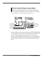
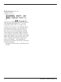
BREATH
VIRTUAL ACOUSTIC TONE GENERATOR
PLAY EDIT
UTIL EFFECT
PHONES
Service charges incurred due to a lack of knowledge
relating to how a function or effect works (when the unit is
operating as designed) are not covered by the manufacturer’s warranty, and are therefore the owners responsibility. Please study this manual carefully and consult your
dealer before requesting service.
92-BP
Battery Notice:
BC/WX
VELOCITY
TOUCH EG
POWER/VOL
MODE BREATH
MIDI/
WX
PART
ENTER
SELECT
EXIT
VALUE
ALL
VOICE
VL-XG
PART
MIDI
BANK/PGM# VOL EXP PAN REV CHO VAR KEY
PUSH ON/OFF
Model
Serial No.
Purchase Date
PLEASE KEEP THIS MANUAL
* The serial number of this product is shown at the rear panel.
Thank you for choosing a Yamaha VL70-m Virtual Acoustic
Tone Generator. The VL70-m is a monophonic tone generator incorporating Yamaha’s revolutionary “Virtual Acoustic Synthesis” tone
generation system — based on the most advanced computer physical
modeling technology. Virtual Acoustic Synthesis produces sound that
is more realistic, more expressive, and more musical than any other
system available at this time. The VL70-m includes 256 preset
voices, from super-realistic to innovative, that can add a new dimension to your sound … whether you play a keyboard, wind controller,
MIDI guitar synthesizer, or use a sequencer to create music.
Please read this owner’s manual carefully, and follow the
instructions within in order to ensure proper operation. Also keep
this manual in a safe place for later reference.
About the Manual
The VL70-m is a very unique tone generator that operates on totally new
principles that were simply unheard of until Yamaha released the worlds first
“Virtual Acoustic” synthesizer based on computer physical modelling. If you’ve
had some experience with the Yamaha VL1, VL1-m, VL-7, or their “Version 2”
upgrades, you will have very little trouble understanding the VL70-m. If you are
new to VA synthesis, however, you will need a little background before attempting to edit and modify voices. We urge you to read the following section of this
manual — “Virtual Acoustic Synthesis — before getting into the details. It will
make a huge difference in how quickly you understand the VL70-m system, and
how efficiently you will be able to edit voices to create the sound you’re looking for.
Other than the above, the structure of the manual is fairly straightforward. You
can approach it in a “linear” manner, reading through from beginning to end, or
on an “on demand” basis, going directly to the information you need as you
need it. Use the table of contents at the beginning, and the index at the end of
the manual to find the information you need.
Conventions
The following conventions are used through the VL70-m manuals to avoid
confusion and make the text easier to read.
■ Buttons & Controls
Button and control names used on the VL70-m panel appear in the text in
capital letters within square brackets: “the [ENTER] button”, for example.
■ Parameter Ranges
An ellipsis is used to indicate a range of parameter values: e.g. “0 … 127”. This
minimizes the confusion sometimes caused by the use of a hyphen or dash for
this purpose.
About the Manual
1
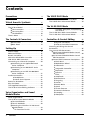
Contents
Precautions
4
Virtual Acoustic Synthesis
6
VA Advantages . . . . . . . . . . . . . . . . . . . . . . . 6
The VL70-m Model . . . . . . . . . . . . . . . . . . . . 7
■ The Instrument . . . . . . . . . . . . . . . . . . . 8
■ The Controllers . . . . . . . . . . . . . . . . . . . 9
■ The Modifiers . . . . . . . . . . . . . . . . . . . 10
There’s More … . . . . . . . . . . . . . . . . . . . . . . 11
The Controls & Connectors
■
■
Front Panel . . . . . . . . . . . . . . . . . . . . . 12
Rear Panel . . . . . . . . . . . . . . . . . . . . . . 14
Setting Up
Power Supply . . . . . . . . . . . . . . . . . . . . . . . .
MIDI Connections . . . . . . . . . . . . . . . . . . . .
Breath Controller . . . . . . . . . . . . . . . . . . . . .
WX-series Wind MIDI Controller . . . . . . . .
G50 Guitar MIDI Converter . . . . . . . . . . . . .
Connecting to a Personal Computer . . . . .
■ Connecting to an Apple Macintosh
Series Computer . . . . . . . . . . . . . . . . .
■ Connecting to an IBM PC/AT Series
Computer . . . . . . . . . . . . . . . . . . . . . . .
■ Connecting to an NEC PC-9801/9821
Series Computer . . . . . . . . . . . . . . . . .
Audio Connections . . . . . . . . . . . . . . . . . . .
● Headphones . . . . . . . . . . . . . . . . . .
● Stereo Sound System . . . . . . . . . . .
Power-on Procedure . . . . . . . . . . . . . . . . . .
Play the Demo . . . . . . . . . . . . . . . . . . . . . . .
The Supplied Demo Disk . . . . . . . . . . . . . . .
The VL70-m Voice Editing Software . . . . .
Voice Organization and Sound
Module Modes
Voice Organization . . . . . . . . . . . . . . . . . . .
The VL70-m Sound Module Modes . . . . . .
■ The VOICE Mode . . . . . . . . . . . . . . . . .
■ The VL-XG Mode . . . . . . . . . . . . . . . . .
■ Selecting the VOICE or VL-XG Sound
Module Mode . . . . . . . . . . . . . . . . . . .
● VL Extension for XG . . . . . . . . . . .
2
12
Contents
15
15
16
17
18
19
20
20
21
21
22
22
22
23
24
25
25
26
26
27
27
28
29
30
The VOICE PLAY Mode
31
The VOICE PLAY Main Control Mode . . . . 31
The VOICE PLAY Sub-control Mode . . . . . . 34
The VL-XG PLAY Mode
36
A Simple XG System Incorporating
the VL70-m . . . . . . . . . . . . . . . . . . . 36
The VL-XG PLAY Main Control Mode . . . . 37
The VL-XG PLAY Sub-control Mode . . . . . . 40
●
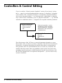
Controllers & Control Editing
Physical Controllers . . . . . . . . . . . .
VL70-m Controller Parameters . . .
Accessing & Editing the Control
Parameters . . . . . . . . . . . . . . . . . . . . . . . . . .
The Control Edit Parameters . . . . . . . . . . .
■ VOICE Sound Module Mode Control
Edit Parameters . . . . . . . . . . . . . . . . . .
■ VL-XG Sound Module Mode Control
Edit Parameters . . . . . . . . . . . . . . . . . .
■ Control Edit Parameter Descriptions .
● Pitch Bend . . . . . . . . . . . . . . . . . . .
● Modulation Wheel . . . . . . . . . . . .
● Aftertouch . . . . . . . . . . . . . . . . . . .
● Assignable Controller . . . . . . . . . .
● Expression . . . . . . . . . . . . . . . . . . .
● Pressure . . . . . . . . . . . . . . . . . . . . .
● Filter . . . . . . . . . . . . . . . . . . . . . . . .
● Amplitude . . . . . . . . . . . . . . . . . . .
● Embouchure . . . . . . . . . . . . . . . . . .
● Tonguing . . . . . . . . . . . . . . . . . . . .
● Scream . . . . . . . . . . . . . . . . . . . . . .
● Breath Noise . . . . . . . . . . . . . . . . .
● Growl . . . . . . . . . . . . . . . . . . . . . . .
● Throat Formant . . . . . . . . . . . . . . .
● Harmonic Enhancer . . . . . . . . . . . .
● Damping . . . . . . . . . . . . . . . . . . . . .
● Absorption . . . . . . . . . . . . . . . . . . .
●
●
42
43
45
46
48
48
50
52
52
53
53
54
54
55
55
56
57
58
59
60
61
62
62
63
64
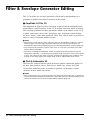
Filter & Envelope Generator Editing
66
Amplitude & Filter EG . . . . . . . . . .
Pitch & Embouchre EG . . . . . . . . .
Accessing & Editing the Filter &
EG Parameters . . . . . . . . . . . . . . . . . . . . . . .
The Filter & EG Edit Parameters . . . . . . . .
■ VOICE Sound Module Mode Filter &
EG Edit Parameters . . . . . . . . . . . . . . .
■ VL-XG Sound Module Mode Filter &
EG Edit Parameters . . . . . . . . . . . . . . .
■ Filter & EG Edit Parameter
Descriptions . . . . . . . . . . . . . . . . . . . . .
● Filter . . . . . . . . . . . . . . . . . . . . . . . .
● Amplitude & Filter Envelope . . . .
● Pitch & Embouchure Envelope . . .
66
66
●
●
Other Edit Parameters
Accessing & Editing the “Others”
Parameters . . . . . . . . . . . . . . . . . . . . . . . . . .
The “Others” Edit Parameters . . . . . . . . . .
■ VOICE Sound Module Mode
“Others” Edit Parameters . . . . . . . . .
■ VL-XG Sound Module Mode
“Others” Edit Parameters . . . . . . . . .
■ “Others” Edit Parameter Descriptions
● Vibrato . . . . . . . . . . . . . . . . . . . . . .
● Detune & Voice Level . . . . . . . . . .
● Assignment & Expansion . . . . . . .
● Velocity Sensitivity . . . . . . . . . . . . .
● Note Limits . . . . . . . . . . . . . . . . . . .
● Portamento . . . . . . . . . . . . . . . . . .
● Dry Level & Voice Name . . . . . . . .
The Store Function
67
69
69
70
71
71
72
73
75
75
77
77
78
79
79
79
80
81
81
82
82
84
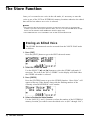
Storing an Edited Voice . . . . . . . . . . . . . . . 84
Effects & Effect Editing
86
Effect Signal Flow . . . . . . . . . . . . . . . . . . . .
● When the Variation Stage is
an Insertion Effect . . . . . . . . . . . . .
● When the Variation Stage is
a System Effect . . . . . . . . . . . . . . .
Accessing & Editing the Effect Parameters
The Reverb Parameters . . . . . . . . . . . . . . . .
The Chorus Parameters . . . . . . . . . . . . . . . .
The Variation Parameters . . . . . . . . . . . . . .
The Distortion Parameters . . . . . . . . . . . . .
Breath Settings
86
86
87
88
90
91
92
94
95
Accessing & Editing the Breath Parameters 95
The Breath Parameters . . . . . . . . . . . . . . . . 96
The Utility Mode
97
The System Parameters . . . . . . . . . . . . . . . . 98
The Dump Out Function . . . . . . . . . . . . . . 100
● DUMPOUT Operation . . . . . . . . . 100
The Initialize Function . . . . . . . . . . . . . . . 102
Appendix
103
Show Control Change . . . . . . . . . . . . . . . .
Show Exclusive . . . . . . . . . . . . . . . . . . . . . .
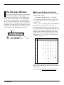
The Message Window . . . . . . . . . . . . . . . .
● Message Window Data Format .
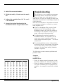
Bitmap Window . . . . . . . . . . . . . . . . . . . . .
● Bitmap Window Data Format . .
● Creating Bitmap Data . . . . . . . . .
Checksum . . . . . . . . . . . . . . . . . . . . . . . . . .
Troubleshooting . . . . . . . . . . . . . . . . . . . . .
Answers to Some Common Questions . .
Error Messages . . . . . . . . . . . . . . . . . . . . . .
Specifications . . . . . . . . . . . . . . . . . . . . . . .
Index
103
103
104
104
105
105
105
106
107
110
112
113
114
Contents
3
Precautions
!! PLEASE READ THIS BEFORE PROCEEDING !!
■ Location
Do not expose the instrument to the following conditions to avoid deformation,
discoloration, or more serious damage.
• Direct sunlight (e.g. near a window).
• High temperatures (e.g. near a heat source, outside, or in a car during the
daytime).
• Excessive humidity.
• Excessive dust.
• Strong vibration.
■ Power Supply
• Turn the power switch OFF when the instrument is not in use.
• The power adaptor should be unplugged from the AC outlet if the instrument
is not to be used for an extended period of time.
• Unplug the instrument during electric storms.
• Avoid plugging the instrument into the same AC outlet as appliances with
high power consumption, such as electric heaters or ovens. Also avoid using
multi-plug adaptors since these can result in reduced sound quality and
possibly damage.
■ Turn Power OFF When Making Connections
• To avoid damage to the instrument and other devices to which it is connected (a sound system, for example), turn the power switches of all related
devices OFF prior to connecting or disconnecting audio and MIDI cables.
■ MIDI Connections
• When connecting the VL70-m to MIDI equipment, be sure to use highquality cables made especially for MIDI data transmission.
• Avoid MIDI cables longer than about 15 meters. Longer cables can pick up
electrical noise that can causes data errors.
■ Handling and Transport
• Never apply excessive force to the controls, connectors or other parts of the
instrument.
• Always unplug cables by gripping the plug firmly, not by pulling on the
cable.
• Disconnect all cables before moving the instrument.
• Physical shocks caused by dropping, bumping, or placing heavy objects on
the instrument can result in scratches and more serious damage.
4
Precautions
■
•
•
•
Cleaning
Clean the cabinet and panel with a dry soft cloth.
A slightly damp cloth may be used to remove stubborn grime and dirt.
Never use cleaners such as alcohol or thinner.
■ Electrical Interference
• This instrument contains digital circuitry and may cause interference if
placed too close to radio or television receivers. If this occurs, move the
instrument further away from the affected equipment.
■ Data Backup
• The VL70-m contains a special long-life battery that retains the contents of
its internal memory even when the power is turned OFF. The backup battery
should last for several years. When the backup battery needs to be replaced
“Battery Low!” will appear on the display when the power is turned on.
When this happens, have the backup battery replaced by qualified Yamaha
service personnel. DO NOT ATTEMPT TO REPLACE THE BACKUP
BATTERY YOURSELF!
■ Service and Modification
• The VL70-m contains no user serviceable parts. Opening it or tampering
with it in any way can lead to irreparable damage and possibly electric
shock. Refer all servicing to qualified YAMAHA personnel.
■ Third-party Software
• Yamaha can not take any responsibility for software produced for this
product by third-party manufacturers. Please direct any questions or comments about such software to the manufacturer or their agents.
YAMAHA is not responsible for damage caused by improper handling or operation.
Precautions
5
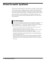
Virtual Acoustic Synthesis
Unlike previous tone generation systems which use oscillators, function generators, preset waveforms or samples to produce sound, Yamaha Virtual Acoustic
(“VA”) Synthesis applies sophisticated computer-based “physical modeling”
technology to musical sound synthesis. In the same way that computer “models”
are used to simulate weather systems or the flight characteristics of aircraft in
the design stage, the VL70-m simulates the very complex vibrations, resonances, reflections and other acoustic phenomena that occur in a real wind or
string instrument.
VA Advantages
The VL70-m offers many advantages in terms of musical performance. Not
just in terms of sound, but also in terms of the “behavior” that makes
acoustic instruments so … well, musical! Yamaha Virtual Acoustic Synthesis is
simply the most musical tone generation system ever created.
• The VL70-m sounds better, has more depth, and is more realistic in the
musical sense than any other tone generation system.
• Simply playing a note in the same way does not always produce precisely
the same sound. The instrument is responsive and “alive”.
• Note-to-note transitions have the same continuity exhibited by acoustic
instruments. What goes on in between the notes is just as important musically as the notes themselves.
• It has extraordinary expressive capability. Rather than simply controlling
parameters like volume or pitch, you can control characteristics such as
breath and reed pressure with appropriate complex effects on the timbre of
the sound.
6
Virtual Acoustic Synthesis
The VL70-m Model
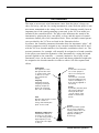
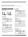
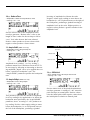
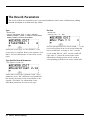
The overall VL70-m model or “algorithm” consists of three main blocks:
the instrument, controllers, and modifiers. In schematic form these blocks
are arranged as follows:
Controllers (also envelopes)
Instrument
Modifiers
Sound out
Virtual Acoustic Synthesis
7
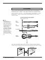
The Instrument
The key block in this algorithm is the instrument, since it is here that the
fundamental tone or “timbre” of the sound is defined. The instrument model
consists primarily of a driver — the reed/mouthpiece, lip/mouthpiece, or bow/
string system — and a resonant system corresponding to the tube and air
column or string.
In all these instruments pressure applied
here (the driving point) causes vibration
which results in sound.
■ NOTES
• The sound thus
produced is amplified
and sustained by the
body of the instrument.
Reed
vibration
• The pitch of the sound
is determined by the
length of the air
column or string, and
the timbre is a complex
product of the driving
source (reed, lip, air,
string), the shape of
the resonant cavity, the
materials from which
the instrument is made,
etc.
Lip
vibration
Air vibration
String
vibration
One of the remarkable features of the VL70-m’s Virtual Acoustic Synthesis
system is that just about any driver can be used with any type of pipe or string.
Drivers
8
Virtual Acoustic Synthesis
Pipes/String
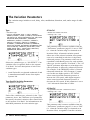
The Controllers
The input to an acoustic wind instrument comes from the player’s lungs, trachea, oral cavity, and lips. In a string instrument it comes from the player’s arm
movement, transmitted to the string via a bow. These elements actually form an
important part of the sound generating system and, in the VL70-m model, are
included in the controllers block. The player also influences the sound of the
instrument by playing the keys, tone holes, or frets, and this aspect of control
constitutes another part of the controllers block. These and other control parameters provided by the VL70-m are listed in the illustration below.
In essence, the controller parameters determine how the instrument “plays”. All
of these parameters can be assigned to any external controller that can be used
with the VL70-m: breath controller, foot controller, modulation wheel, etc. The
pressure parameter, for example, will normally be assigned to a breath controller
so the player can control the dynamics of the instrument by varying the breath
pressure applied to the controller — a natural, instinctive way to play windinstrument voices. At the same time the growl and throat parameters might also
be assigned to the breath controller in order to achieve life-like response and
effects.
Embouchure
The tightness of the
lips against the reed
or against each other,
or the force of the
bow against the
string.
Tonguing
Simulates the halftonguing technique
used by saxophone
players by changing
the “slit” of the reed.
Pitch
Changes the length of
the air column or
string, and thereby the
pitch of the sound.
Damping & Absorption
Simulate the effects of
air friction in the pipe
or on the string, and of
high-frequency losses
at the end of the pipe
or string.
Throat
Controls the characteristics of the “player’s”
throat or bowing arm.
Pressure
The amount of breath
pressure applied to the
reed or mouthpiece, or
bow velocity applied to
the string.
Growl
A periodic pressure (bow
velocity) modulation
which produces the
“growl” effect often
heard in wind instruments.
Scream
Drives the entire system
into chaotic oscillation,
creating effects that can
only be achieved with
physical modelling
technology.
Virtual Acoustic Synthesis
9
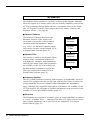
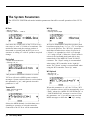
The Modifiers
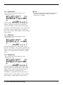
The modifiers block consists of 4 sections as shown in the diagram. Although
these may appear to be simple effects, they are actually intimately related to the
VL70-m’s sound-producing model and have a significant effect on the sound
(the VL70-m has a separate effects stage with reverb, chorus, variation, and
distortion effects — see page 86).
● Harmonic Enhancer
The Harmonic Enhancer determines the
harmonic structure of the sound to the
extent that it can produce radical timbral
variations within an instrument “family”
(e.g. saxes). The harmonic enhancer parameters can be accessed via the Yamaha VL70m Expert Editor software (page 25).
● Dynamic Filter
This section is similar to the dynamic filters
found in many conventional synthesizers,
with high-pass, bandpass, band elimination,
and low-pass modes. Some filter parameters
are available via the VL70-m controls, but
detailed editing of parameters such as the
filter type requires the Yamaha VL70-m
Expert Editor software (page 25)
Harmonic
Enhancer
Dynamic
Filter
Frequency
Equalizer
Resonator
● Frequency Equalizer
This is a 5-band parametric equalizer with frequency, Q (bandwidth), and level
control. The equalizer also has pre-EQ high- and low-pass filters as well as key
scaling capability for precise response control throughout the instrument’s
range. Although only simplified treble and bass parameters are available via the
VL70-m controls, the full range of equalizer parameters can be accessed via the
Yamaha VL70-m Expert Editor software (page 25).
● Resonator
The Resonator uses simulated “resonator” pipes or strings and delays to produce
a “woody” resonance effect — although it has little or no effect on some voices.
The resonator parameters can be accessed via the Yamaha VL70-m Expert
Editor software (page 25).
10 Virtual Acoustic Synthesis
There’s More …
In this brief introduction to VL70-m basics we’ve only looked at the central
physical model which is the key the VL70-m’s unprecedented sound and
musical performance. There’s actually much more to it. There’s also an extensive range of other functions and features that are similar to those you may be
familiar with from conventional synthesizers. There are, for example, programmable envelopes that can be applied to most of the controllers in addition to
real-time player control. And, of course, there’s a comprehensive selection of
utility functions that give the VL70-m maximum versatility and convenience.
Now that you understand the basics, dive in and find out what the VL70-m can
really do.
Virtual Acoustic Synthesis 11
The Controls & Connectors
The following brief descriptions of the VL70-m controls and connectors
should help you to understand the overall logic of the interface.
Front Panel
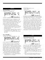
q [POWER/VOL] Control
Press to turn power ON or OFF. Rotate to adjust
overall output volume (clockwise to increase the
volume).
pressing the [PLAY] button causes the currently
selected voice to sound — a convenient test
feature.
➲ page 31
w Breath Controller Jack
An optional Yamaha BC3, BC2 or BC1 Breath
Controller can be plugged in here.
➲ page 17
u [EDIT] Button
Activates the VL70-m EDIT mode in which
voices can be edited to create new sounds.
➲ page 46
e WX IN Jack
Allows direct connection of a Yamaha WXseries Wind MIDI Controller such as the WX11
or WX7, without the need for a WT11 or BT7
wind controller interface.
➲ page 18
i [UTIL] Button
Selects the VL70-m UTILITY mode. The
UTILITY mode includes a range of important
utility functions that affect operation of the
VL70-m: SYSTEM SETUP, DUMP OUT,
INITIALIZE, and DEMO SONG.
➲ page 97
r PHONES Jack
Accepts a standard pair of stereo headphones
(stereo mini phone plug) for headphone monitoring of the VL70-m sound without the need for
external amplification equipment. The volume of
the headphone sound is adjusted via the
[POWER/VOL] control.
t Display
This large backlit liquid crystal display panel
shows all parameters and prompts necessary for
easy, efficient operation and programming of the
VL70-m. The display contrast can be adjusted as
described on page 99.
➲ page 31
y [PLAY] Button
Press this button to select the VL70-m PLAY
mode in which voices can be selected and
played. If the PLAY mode is already selected,
12 The Controls & Connectors
o [EFFECT] Button
Selects the VL70-m EFFECT mode in which the
built-in reverb, chorus, variation, and distortion
effects can be assigned and edited as required.
➲ page 88
!0 [MODE] Button
Accesses the VL70-m sound module mode
selection function.
➲ page 29
!1 [BREATH] Button
Selects the BREATH SETTING which includes
parameters that determine how the VL70-m
responds to control from a breath controller,
WX-series Wind MIDI Controller, or similar
device.
➲ page 95
!2 [MIDI/WX] Button
Pressing this button alternately selects the VL70m MIDI and WX control modes (when the rearpanel HOST SELECT switch is set to Mac, PC1, PC-2).
➲ page 18
!3 [ENTER] Button
The [ENTER] button is used to engage submodes, confirm input, and execute certain
operations. Double-clicking this button (i.e.
press the button twice in rapid succession)
provides access to the SHOW CONTROL and
SHOW EXCLUSIVE (page 103) modes.
➲ page 24
!4 [EXIT] Button
This button is used to exit from sub-modes and
cancel certain operations. No matter where you
are in the VL70-m display structure, pressing the
[EXIT] button (a number of times if necessary)
will eventually return you to the PLAY mode.
➲ page 24
!5 PART [-] and [+] Buttons
When the VL-XG sound module mode is selected (page 28) these buttons select the part to
be played. Either button can be pressed briefly
for single stepping in the specified direction, or
held for continuous scrolling. In either the VLe
XG or VOICE sound module mode (page 27)
pressing both buttons simultaneously switches in
and out of the PLAY mode sub-control mode
(pages 34 and 40).
When the EDIT mode is selected the PART
buttons can be used to switch between parameters without having to return to the EDIT mode
menu.
➲ page 36
!6 SELECT [<] and [>] Buttons
These buttons are used to select sub-modes or
parameters. In some cases the selection will be
made from a menu displays, and in others the
SELECT buttons will actually switch display
pages.
➲ page 31
!7 VALUE [-] and [+] Buttons
Used to select voices and edit parameter values.
Either button can be pressed briefly for single
stepping in the specified direction, or held for
continuous scrolling. They also have a large-step
function which allows you to skip ahead or
backward in larger increments when selecting
voices or editing numeric parameters: press
either the [-] or [+] button while holding the
other button.
➲ page 31
w
WX IN
y u i o !0 !1
BREATH
VIRTUAL ACOUSTIC TONE GENERATOR
PLAY EDIT
UTIL EFFECT
PHONES
BC/WX
VELOCITY
TOUCH EG
POWER/VOL
MODE BREATH
MIDI/
WX
PART
ENTER
SELECT
EXIT
VALUE
ALL
VOICE
VL-XG
PART
MIDI
BANK/PGM# VOL EXP PAN REV CHO VAR KEY
!5
!6
!7
PUSH ON/OFF
r
q
t
!2 !3 !4
The Controls & Connectors 13
Rear Panel
!8 DC IN Connector
The DC output cable from the Yamaha PA-3B
AC Power Adaptor supplied with the VL70-m is
plugged in here.
➲ page 15
!9 OUTPUT L/MONO and R Jacks
These are the main stereo outputs from the
VL70-m. Be sure to connect both outputs to the
appropriate channels of a stereo sound system in
order to appreciate the full quality of the VL70m sound and effects. The L/MONO jack can be
used alone when connecting to a mono sound
system (e.g. a musical instrument amplifier).
➲ page 22
@0 MIDI IN, OUT and THRU Connectors
The MIDI IN connector receives the data from
an external sequencer or other MIDI device
which is to control or transmit data to the VL70m. The MIDI THRU connector simply retransmits the data received at the MIDI IN
connector, allowing convenient chaining of
MIDI devices. The MIDI OUT connector
transmits data corresponding to VL70-m Breath
Controller operation, or bulk data when one of
the MIDI data transmission functions are activated. The MIDI OUT connector can also be
used to “echo” (re-transmit) data received via
the MIDI IN or TO HOST connectors.
➲ page 16
@1 TO HOST Connector & HOST SELECT Switch
This jack and selector switch allow direct
connection to a personal computer for sequencing and other music applications — without the
need for a separate MIDI interface.
➲ page 20
MIDI
MIDI
Mac
PC-2 PC-1
THRU
OUT
OUTPUT
HOST SELECT
TO HOST
DC IN
R
L/MONO
IN
SER NO.
@0
14 The Controls & Connectors
@1
!8
!9
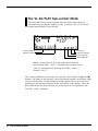
Setting Up
Power Supply
Your VL70-m comes supplied with a Yamaha PA-3B AC adaptor. Plug the
DC output cable from the AC adaptor into the DC IN jack on the rear panel,
then plug the adaptor into a convenient wall AC power socket. It is also a good
idea to clip the adaptor’s DC cable into the cable clip on the VL70-m rear panel
to minimize the possibility of accidentally unplugging the cable during operation.
■ CAUTION
• Do not attempt to use an AC adaptor other than the supplied unit or an appropriate
replacement provided by your Yamaha dealer to power the VL70-m. The use of an
incompatible adaptor may cause irreparable damage to the VL70-m, and might pose a
serious shock hazard!
• Be sure to unplug the AC adaptor from the AC mains socket when the VL70-m is not in
use.
DC-IN
OUTPUT
HOST SELECT
MIDI
Mac
PC-2 PC-1
TO HOST
DC IN
R
L/MONO
SER NO.
PA-3B
AC power socket
Setting Up 15
MIDI Connections
The VL70-m can be used with virtually any type of MIDI controller: keyboard, wind controller, sequencer, etc. To ensure reliable error-free transfer
of MIDI data always use high-quality MIDI cables obtained from your Yamaha
dealer or music equipment store. Also avoid MIDI cables that are longer than
about 15 meters, since cables longer than this can pick up noise which can
cause data errors.
The VL70-m MIDI receive channel and device number parameters are available
via the PLAY mode display and PLAY mode sub-control display (pages 32 and
34). Make sure these parameters are set to match the corresponding settings of
the MIDI controller used with the VL70-m.
● The VL70-m receives the following MIDI data:
Note
The played note and velocity values.
Control Change
Modulation wheel, breath controller, foot controller, sustain, and
other controller data.
Aftertouch
Keyboard aftertouch pressure (channel aftertouch only).
Pitch Bend
Pitch bend wheel position.
Program Change Voice numbers and bank select messages.
& Bank Select
System Exclusive Voice and system data transmitted in the form of “bulk dumps.”
■ NOTES
• IMPORTANT!: The rear-panel HOST SELECT switch must be set to “MIDI” when the VL70m is not connected to a computer via the TO HOST connector.
• For detailed MIDI specifications refer to the “MIDI Data Format” on page 26 of the List
Book.
• When using the VL70-m with other MIDI equipment, it is a good idea to refer to the
MIDI specifications (implementation chart, MIDI data format) of the equipment used to
ensure compatibility.
16 Setting Up
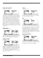
Breath Controller
If you will be using the VL70-m with a keyboard, a breath controller is an
essential expressive tool — both for realistic expression with wind-instrument voices and unprecedented expressive control with string voices. Plug an
optional Yamaha BC3, BC2 or BC1 Breath Controller into the front-panel
breath controller jack. If the controlling MIDI keyboard has a breath controller
jack, it might be more convenient to plug the breath contoller in there rather
than directly into the VL70-m. The Breath Controller is ideal for controlling
parameters that would normally be affected by a wind player’s breath: dynamics, timbre, pitch, and others.
■ IMPORTANT!
• If you will be using a BC3, BC2, or BC1 breath controller plugged into the BREATH jack,
the “Breath Mode” parameter must be set to “BC/WX” (page 96). This is also necessary if
you plug the breath controller into the keyboard’s breath controller jack.
MIDI OUT
MIDI keyboard
MIDI IN
WX IN
BREATH
VIRTUAL ACOUSTIC TONE GENERATOR
PLAY EDIT
UTIL EFFECT
BREATH
PHONES
BC/WX
VELOCITY
TOUCH EG
POWER/VOL
MODE BREATH
MIDI/
WX
PART
ENTER
SELECT
EXIT
VALUE
ALL
VOICE
VL-XG
PART
MIDI
BANK/PGM# VOL EXP PAN REV CHO VAR KEY
PUSH ON/OFF
BC3
VL70-m
Setting Up 17
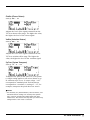
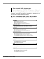
WX-series Wind MIDI Controller
The VL70-m is an ideal tone generator for use with a Yamaha WX-series
Wind MIDI Controller such as the WX11 or WX7. In either case the controller can be plugged directly into the WX IN connector on the VL70-m front
panel, without the need for a WT11 or BT7 wind controller interface.
WX IN
BREATH
VIRTUAL ACOUSTIC TONE GENERATOR
PLAY EDIT
UTIL EFFECT
WX IN
PHONES
BC/WX
VELOCITY
TOUCH EG
POWER/VOL
MODE BREATH
MIDI/
WX
PART
ENTER
SELECT
EXIT
VALUE
ALL
VOICE
VL-XG
PART
MIDI
BANK/PGM# VOL EXP PAN REV CHO VAR KEY
PUSH ON/OFF
VL70-m
WX11
Special care must be taken with the following parameters and controls when
using a WX-series Wind MIDI Controller:
■ NOTES
• If a WX controller is unplugged while the VL70-m power is on, the breath level may
remain fixed at “0” and subsequently played notes may not sound. If this happens, turn
the VL70-m power off and then on again.
BREATH MODE
The Breath Mode parameter (page 96) must be set to “BC/WX”
in order for the VL70-m to recognize breath data from the
controller.
SOUND MODULE If you intend to drive additional MIDI devices via the VL70-m
MIDI OUT connector when using a Wind MIDI Controller, the
MODE
VL70-m sound module mode should be set to VOICE (page 29).
When the VL-XG mode is selected MIDI note data received via
the MIDI IN connector is not re-transmitted via the MIDI OUT
connector.
18 Setting Up
LIP MODE
WX-series Wind MIDI Controllers produce pitch bend data
ranging from “-16” to “+32” in response to lip (reed) pressure.
The WX Lip parameter (page 98) determines whether these
values are used as is (“Norm”), or expanded to a “-64” through
“+63” range (“Expd”). When the “Expd” mode is selected, the
expanded pitch bend data is also transmitted via the MIDI OUT
connector. The “Expd” setting is recommended when using a
WX controller in the “tight lip” mode. The “Norm” setting is
recommended when using the WX controller “loose lip” mode.
MIDI/WX
SETTING
When the VL70-m is connected to a WX controller and a
computer via the TO HOST connector, and the HOST SELECT
switch is set to any position other than “MIDI”, the front-panel
[MIDI/WX] button must be used to select the “WX” mode (a
small WX icon will appear on the left side of the display) in
order for the VL70-m to recognize data from the WX controller.
When the HOST SELECT switch is set to “MIDI” the VL70-m
accepts both MIDI and WX data (both the MIDI and WX icons
appear on the display), and the [MIDI/WX] button has no effect.
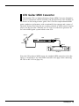
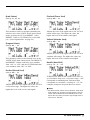
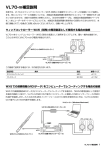
G50 Guitar MIDI Converter
The Yamaha G50 is a high-performance Guitar MIDI Converter designed to
work in conjunction with the Yamaha G1D Divided Pickup Unit installed on
an electric or steel-string acoustic guitar. The G50 offers unprecedented MIDI
guitar synthesizer performance with exceptionally fast response and a range of
advanced features that bring the true creative potential of MIDI control to guitar
players for the first time. Naturally, the VL70-m is an ideal tone generator for
use with a MIDI guitar system based on the G50.
Guitar
G50
MIDI OUT
PARAMETER
GUITAR MIDI CONVERTER
GUITAR SETUP
WRITE
EXTERNAL TG SETUP
A PLAYING STYLE
H PROGRAM CHANGE #
B NOTE ON LEVEL
I
BANK MSB
C NOTE OFF LEVEL
J
BANK LSB
D VELO CITY
K VOLUME
E CHROMATIC
L PAN
F TRANSPOSE
M ASSIGNABLE 1
G PITCH BEND RANGE N
VALUE
O ASSIGNABLE 2
P
VALUE
REALTIME CONTROL
Q SPLIT
R
MEMORY2#
S
MEM2 LOCATION
T PICKING CONTROL
U
FRONT
V
REAR
W TOUCH CONTROL
X
SENSITIVITY
Y SUSTAIN/HOLD PEDAL
G1D
MIDI IN
WX IN
BREATH
VIRTUAL ACOUSTIC TONE GENERATOR
PLAY EDIT
UTIL EFFECT
PHONES
BC/WX
VELOCITY
TOUCH EG
POWER/VOL
MODE BREATH
MIDI/
WX
PART
ENTER
SELECT
EXIT
VALUE
ALL
VOICE
VL-XG
PART
MIDI
BANK/PGM# VOL EXP PAN REV CHO VAR KEY
PUSH ON/OFF
VL70-m
Since the G50 produces MIDI output, the standard MIDI connection rules that
apply to a keyboard or any other MIDI controller also apply when connecting
the G50 to the VL70-m (page 16).
Setting Up 19
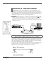
Connecting to a Personal Computer
Although the VL70-m can be connected to a personal computer via the
MIDI IN/OUT connectors and a MIDI interface, the TO HOST connector
and selector switch allow direct connection to Apple Macintosh, IBM PC/AT, or
NEC PC-9801/9821 series personal computers for sequencing and other music
applications without the need for a separate MIDI interface.
■ IMPORTANT!
• If the VL70-m is to be connected to a computer via the TO HOST connector and a MIDI
controller via the MIDI IN connector, the “echo back” function of the music software or
sequencer you are using must be turned “on” so that the MIDI note data from the
controller is returned to the VL70-m and any subsequent devices connected to the VL70m MIDI OUT connector.
●Connector Pin
Numbers
mini Din 8-pin
Modem or
Printer port
MIDI controller
MIDI OUT
6 7 8
3 4 5
1 2
Personal System/V
PS/V
RS-232C
Personal System/V
IBM
D-SUB 9-pin
MIDI IN
5 4 3 2 1
9 8 7 6
WX IN
TO HOST
BREATH
VIRTUAL ACOUSTIC TONE GENERATOR
PLAY EDIT
UTIL EFFECT
D-SUB 25-pin
PHONES
BC/WX
VELOCITY
TOUCH EG
POWER/VOL
MODE BREATH
MIDI/
WX
PART
ENTER
SELECT
EXIT
VALUE
ALL
Personal
computer
VOICE
VL-XG
PART
1 2 3 4 5 6 7 8 9 10 11 12 13
14 15 16 17 18 19 20 21 22 23 24 25
MIDI
BANK/PGM# VOL EXP PAN REV CHO VAR KEY
PUSH ON/OFF
VL70-m
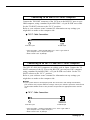
Connecting to an Apple Macintosh Series Computer
Connect the TO HOST connector of the VL70-m to the modem or printer port
on your Macintosh, depending on which port your MIDI software is using for
MIDI data communication, using a standard Macintosh 8-pin system peripheral
cable. Set the TO HOST selector to the “Mac” position.
You may also have to make other MIDI interface settings on the computer side,
depending on the type of software you use (refer to your software owner’s
manual). In any case the clock speed should be set to 1 MHz.
● “Mac” Cable Connections
mini Din 8-pin
• 8-pin system peripheral cable.
• Data transfer rate: 31,250 bps.
20 Setting Up
mini Din 8-pin
Connecting to an IBM PC/AT Series Computer
Connect the TO HOST connector of the VL70-m to the RS-232C port on your
IBM computer, using a standard 8-pin MINI DIN → 9-pin D-SUB cross cable.
Set the TO HOST selector to the “PC-2” position.
Refer to your software owner’s manual for information on any settings you
might have to make on the computer side.
● “PC-2” Cable Connections
mini Din 8-pin
D-SUB 9-pin
• 8-pin mini DIN → 9-pin D-SUB cable. Use a “PC-1” type cable if
your computer uses a 25-pin serial port.
• Data transfer rate: 38,400 bps.
Connecting to an NEC PC-9801/9821 Series Computer
The NEC PC-9801/9821 computers are widely used in Japan. Connect the TO
HOST connector of the VL70-m to the RS-232C port on your NEC computer,
using a standard 8-pin MINI DIN → 25-pin D-SUB cross cable. Set the TO
HOST selector to the “PC-1” position.
Refer to your software owner’s manual for information on any settings you
might have to make on the computer side.
■ NOTES
• If your system doesn’t work properly with the connections and settings listed above,
your software may require different settings. Check your software operation manual and
set the HOST SELECT switch to the position the provides the appropriate data transfer
rate.
● “PC-1” Cable Connections
mini Din 8-pin
D-SUB 25-pin
• 8-pin mini DIN → 25-pin D-SUB cable. Use a “PC-2” type cable if
your computer uses a 9-pin serial port.
• Data transfer rate: 31,250 bps.
Setting Up 21
Audio Connections
■ Headphones
For private listening and practice headphones are ideal. You don’t have to
hook up and complete sound system, and you won’t disturb the neighbors no
matter how loud or late you play. Any standard pair of stereo headphones with a
stereo mini phone plug and an impedance of between about 8 and 150 ohms can
be used.
■ Stereo Sound System
The VL70-m voices and effects are designed to sound their best in stereo, so
you should always use a stereo sound system to appreciate the full impact of the
VL70-m voices and expressive features. The VL70-m OUTPUT L/MONO and
R jacks can be connected directly to musical instrument amplifiers designed for
keyboard use, or to the line inputs of a mixing console. It is also possible to
connect the VL70-m outputs directly to the inputs of a multitrack or stereo tape
recorder.
■ NOTES
• If you need to drive a mono amp or other device, connect only the L/MONO output jack.
The left and right channel signals are automatically combined and delivered via the L/
MONO jack when a single phone plug is inserted in this jack and the R output jack is left
unconnected.
• Make sure that both the VL70-m and your sound system are turned OFF when making
connections.
22 Setting Up
Power-on Procedure
Always follow proper procedure when powering-up a sound system to
minimize the possibility of damage to the equipment (and your ears!).
1. Make sure your sound system’s main level/volume control(s) and the
VL70-m volume control are turned all the way down prior to turning
power on.
2. Turn on the VL70-m.
3. Turn on your MIDI controller (and computer/sequencer, if used).
4. Turn on the sound system.
5. Raise the sound system volume to a reasonable level.
6. Gradually raise the VL70-m VOLUME control while playing the MIDI
controller to set the desired listening level.
■ NOTES
• Some keyboards and other MIDI controllers automatically transmit MIDI control change
data corresponding to their control status when the power switch is turned ON or OFF.
The VL70-m is programmed to receive this data and respond accordingly, so it is preferable to turn the VL70-m ON before turning the controlling device ON.
Setting Up 23
Play the Demo
Once you’ve set up your VL70-m system, you might like to play the preprogrammed demo sequence to hear how some of the voices sound. This
process will also help to familiarize you with some of the VL70-m’s selection
and editing procedures.
■ NOTES
• When the demo is played all system setup parameters and current voice are initialized. If
your VL70-m memory contains data you want to keep, be sure to use the bulk dump
function (page 100) to save the data to an external MIDI data recorder or other appropriate storage device before playing the demo.
1. Select the Utility Mode
Press the [UTILITY] button to select the utility mode.
2. Select the Demo Mode
Use the SELECT [<] and [>] buttons to select the “DEMO” mode.
3. Press [ENTER] and Confirm
Press the [ENTER] button if it’s OK to go ahead with the demo. The VL70m will ask you to confirm: press [ENTER] again to proceed to the demo
song select display, or [EXIT] to abort.
4. Select a Song
Use the VALUE [-] and [+] buttons to select the demo song number you
want to start with.
5. Run the Demo
Press the [ENTER] button to run the demo. Playback will start with the
selected song, then all other songs will be played in sequence. The cycle will
repeat until stopped.
6. Stop the Demo
Press the [EXIT] button to stop demo playback. This will return you to the
demo song select display.
7. Return To the Play Mode When Done
Press the [PLAY] button to return to the PLAY mode.
24 Setting Up
The Supplied Demo Disk
The VL70-m is supplied with a demonstration data disk which contains
several songs which demonstrate some of the VL70-m’s advanced musical
capabilities. The songs on this disk can be reproduced using any sequencer or
computer-based sequence software which can handle SMF (Standard MIDI File
— format 0) song files.
All of the demo songs use the VL70-m for the main melody line, while a
second XG tone generator (Yamaha MU50 or MU80 for example) supplies the
backing.
■ NOTES
• The supplied disk is a 2DD type (720 kilobytes) using MS-DOS format. The disk can be
read by Macintosh computers by using the PC Exchange application and an application
such as ResEdit which can change the file’s file type.
The VL70-m Voice Editing Software
— What It Is & Where To Get It —
The range of parameters accessible via the VL70-m programming interface
is limited to the simplest “upper level” of virtual acoustic synthesis parameters.
The “core” parameters which are the true foundation of physical modeling are
extremely complex, and were therefore not made directly accessible.
The VL70-m Expert Editor voice editing software provides full access to the
complete range of physical modeling parameters. It can be used alone to create
new voices, or edit voices loaded from the VL70-m. The VL70-m Expert Editor
is basically a refined version of the editing software Yamaha voicing professionals use to create original voices for VL-series synthesizers and tone generators.
It therefore gives you full professional-level programming power and potential.
Another handy VL editing software is the VL Visual Editor. The VL Visual
Editor makes it easy for anyone to create new VL voices via a graphic, easy-touse editing interface. The VL70-m Expert Editor can read voice files created by
the VL Visual Editor, allowing further in-depth programming.
The VL Voice Editing Software can be obtained via Yamaha’s XG
home page on the World Wide Web, “http://www.yamaha.co.jp./english/xg/html/
libhm.html”.
Setting Up 25
Voice Organization and Sound Module
Modes
Voice Organization
The VL70-m voices are organized into four main banks. Additional banks
are used when the VL70-m is set to operate in the VL-XG sound module
mode (page 29). The four main banks are as follows:
PRESET 1
The PRESET 1 bank contains 128 preset voices which have been
created primarily to be played via a keyboard.
PRESET 2
The PRESET 2 bank contains 128 preset voices which have been
created to provide maximum expressive capability when played
with a breath controller or WX-series Wind MIDI Controller.
CUSTOM
The CUSTOM bank has 6 memory locations in which voices can
be edited in detail via an appropriate personal computer and
the Yamaha VL70-m Expert Editor application software (page
25). When the VL70-m is initially shipped CUSTOM voice numbers 001 through 006 contain a selection of sound-effect type
voices from the PRESET banks.
INTERNAL
The INTERNAL bank has 64 memory locations in which voices
you have edited can be stored and easy recalled for use as
required. Unlike CUSTOM voices, INTERNAL voices can be edited
via the VL70-m panel controls. When the VL70-m is initially
shipped INTERNAL voice numbers 001 through 064 contain a
selection of voices from the PRESET 1 and PRESET 2 banks, set
up to be played via a WX-series Wind MIDI Controller.
Banks 112 through 119 become available when the VL70-m is set to the VL-XG
sound module mode (page 29). In the VL-XG sound module mode some voices
from the PRESET 1 and PRESET 2 banks are assigned MIDI bank and program
change numbers conforming to the Yamaha XG format. Since the VL70-m does
not have a full set of XG-compatible voices, however, some voice numbers will
be skipped (e.g. 23, 24, 27, etc.).
■ NOTES
• PRESET 1, PRESET 2, and CUSTOM voices can be edited via the VL70-m panel controls,
but the edited voices cannot be stored to the PRESET 1, PRESET 2, or CUSTOM bank.
Edited voices can only be stored to the INTERNAL bank, and only when the VL70-m is set
to the VOICE sound module mode (page 29).
• The factory preset CUSTOM and INTERNAL
voices can be restored by using the Factory Set
Initialize function described on page 102.
• Refer to the separate “List Book” for a complete listing of the VL70-m voices.
• Use the MIDI bank MSB (control number 00)
and LSB (control number 32) numbers listed at
right to select VL70-m banks from an external
MIDI device. In the VOICE sound module mode,
the MSB is ignored (recognized as 33) and only
LSB numbers 0 through 3 are recognized.
26 Voice Organization and Sound Module Modes
BANK
PRESET 1
PRESET 2
CUSTOM
INTERNAL
BANK 112
BANK 113
BANK 114
BANK 115
BANK 116
BANK 117
BANK 118
BANK 119
MSB
33
33
33
33
97 or
97 or
97 or
97 or
97 or
97 or
97 or
97 or
81
81
81
81
81
81
81
81
LSB
0
1
2
3
112
113
114
115
116
117
118
119
The VL70-m Sound Module Modes
The VL70-m has two main Sound Module Modes: VOICE and VL-XG. It is
important to understand the difference between these modes because they
determine how the VL70-m responds to MIDI program change and bank numbers received from a MIDI keyboard or other controller, and how the internal
effects relate to the individual voices.
The VOICE Mode
In this mode the VL70-m functions as a “standard” tone generator module. The
VOICE mode should be used when the VL70-m is being used alone or with
other non-XG tone generators/synthesizers (see “VL Extension for XG”, page
30).
● Voice Selection
The PRESET 1, PRESET 2, CUSTOM, and INTERNAL voices can be individually selected by the VL70-m panel VALUE [-] and [+] buttons, or appropriate MIDI program change numbers and bank numbers received from your
keyboard or controller (see the “Voice Organization” section, above).
● Voice Editing
In the VOICE mode the INTERNAL voices can be individually edited via the
VL70-m panel controls. Each voice has its own edit parameters which can be
stored with the voice are recalled whenever the voice is selected. In fact, the
edited data must be stored with the voice before a new voice is selected otherwise the edited data will be lost.
● Effects
Each voice has its own effect settings which are recalled whenever the voice is
selected, so that effects become an important part of the individual sound of
each voice. As with edited voice data, edited effect data must be stored with the
voice before a new voice is selected otherwise the edited effects data will be
lost.
● MIDI Output
Normally, MIDI data received at the VL70-m MIDI IN connector is re-transmitted “as is” via the MIDI OUT connector. The Note Filter function described on
page 99 can be used to filter out (i.e. block) note data transmission on specified
channels.
Voice Organization and Sound Module Modes 27
The VL-XG Mode
In this mode the VL70-m functions as an “XG expansion” tone generator
module. The VL-XG mode should be selected when the VL70-m is being used
with other XG tone generators/synthesizers to play music data created for tone
generators complying with the Yamaha XG format (see “VL Extension for XG”,
page 30).
● Voice Selection
The PRESET 1, PRESET 2, CUSTOM, and INTERNAL voices can be individually selected by the VL70-m panel VALUE [-] and [+] buttons, or appropriate MIDI program change numbers and bank numbers received from your
keyboard or controller (see the “Voice Organization” section, above). In the VLXG mode banks 112 through 119 become available, and some voices from the
PRESET 1 and PRESET 2 banks are assigned MIDI bank and program change
numbers conforming to the Yamaha XG format. Since the VL70-m does not
have a full set of XG-basic voices, however, some voice numbers will be
skipped (e.g. 23, 24, 27, etc.).
● Voice Editing
In the VL-XG mode only one set of voice parameters is provided for all voices.
Voices can not be individually edited and stored in the INTERNAL bank as in
the VOICE mode. In fact, the VL-XG mode has no store function. Any voice
parameter edits are retained no matter what voice is selected. This allows the
same controller and other settings to be retained while switching to different
voices.
● Effects
In the VL-XG mode only one set of effect parameters is provided for all voices.
Effects can not be edited and stored with each individual voice in the INTERNAL bank as in the VOICE mode. The current effect settings are retained no
matter what voice is selected. This allows the same reverb and other “ambiencedefining” settings to be retained while switching to different voices.
● MIDI Output
Only MIDI messages which are not used by the VL70-m are re-transmitted via
the MIDI OUT connector. The Note Filter function described on page 99 can be
used to filter out (i.e. block) note data transmission on specified channels.
28 Voice Organization and Sound Module Modes
Selecting the VOICE or VL-XG Sound Module Mode
The current sound module mode is indicated by the triangular pointer in the
lower right- corner of the display in the PLAY mode.
VOICE
VL-XG
The VOICE or VL-XG sound module mode is selected as follows:
1. Press the [MODE] Button
Press the [MODE] button access the VL70-m sound module modes selection
function.
2. Select the VOICE or VL-XG Mode
Use the VALUE [-] and [+] buttons to select the “VOICE” or “VL-XG” sound
module mode, as required.
3. Press [EXIT] or [PLAY] When Done
Press the [EXIT] or [PLAY] button to return to the PLAY mode when the
desired sound module mode has been selected.
Voice Organization and Sound Module Modes 29
■ VL Extension for XG
The VL Extension for XG (“VL Extension for XG” is
abbreviated to VL-XG) included in the VL70-m Virtual
Acoustic Tone Generator significantly enhances and
expands the musical capabilities of the XG format with
the superior sound and expressive potential of Yamaha Virtual Acoustic
Synthesis. A VL70-m can be used in conjunction with a Yamaha MU80
or MU50 XG tone generator, for example: the VL70-m providing superior wind and string instrument voices while the MU80 or MU50 supplies
drums, percussion, keyboard, and other voices.
The XG format is basically a set of rules describing how a tone generator
will respond to MIDI data. The current GM (General MIDI) format is a
similar concept, allowing GM music data to be reproduced accurately on
any GM tone generator from any manufacturer. GM, however, applies
only to a limited set of parameters. XG significantly expands on the basic
GM format, providing many more voices, voice editing capability,
effects, external input, and other features that contribute to enhanced
musical expression. And since XG is totally upward compatible with GM,
GM data can be accurately reproduced on any XG tone generator.
* The VL70-m does not contain the basic set for the XG format.
30 Voice Organization and Sound Module Modes
The VOICE PLAY Mode
When the VOICE sound module mode is selected (see “The VL70-m Sound
Module Modes, page 27), pressing the [PLAY] button engages the VL70-m
VOICE PLAY mode. This mode allows voices to be selected and played, and
thus is the mode you’ll normally use when playing the VL70-m. The VOICE
PLAY mode also provides access to several important performance parameters
including volume, panning, etc. The VOICE PLAY mode actually has two
control modes — the main control mode and the sub-control mode — which
provide access to different sets of parameters, as described below.
The VOICE PLAY Main Control Mode
This mode is initially selected when the VL70-m power is turned on. If the
sub-control mode is active (see page 34), the main control mode can be
selected by simultaneously pressing the PART [-] and [+] buttons. The VOICE
PLAY main control mode display looks like this:
PART
• Device Number
• Bank Number
• Program Number
• Volume
MIDI
BANK/PGM
VOL
EXP PAN
REV
CHO
VAR KEY
•
•
•
•
•
System Transpose
Variation Return
Chorus Return
Reverb Return
Pan
The various parameters in this mode are selected via the SELECT [<] and [>]
buttons. The name of the currently selected parameter appears in the upper right
corner of the display (when the bank and program number parameters are
showing a solid triangular pointer indicates which of the two parameters is
selected). A small triangular pointer appears above the icon corresponding to the
selected parameter in the bottom line of the display. Once the desired parameter
has been selected, it’s value can be set as required via the VALUE [-] and [+]
buttons.
The VOICE PLAY Mode 31
DevNo. (Device Number)
Volume
Settings: 001 … 016, all
Settings: 000 … 127
The Device Number parameter must be set properly when you want to transmit or receive MIDI
system exclusive data to or from another VL70-m
or other MIDI device (system exclusive data
includes voice parameters, system setup parameters, etc). The VL70-m Device number must be
set to the same number as the Device Number of
the external device. Select a device number from
“001” to “016”, or “all”. When “all” is selected,
MIDI system exclusive data can be received on all
device numbers, but transmission occurs via device
number 001.
Sets the volume of the current voice. The higher
the value the louder the volume.
(Bank Number)
Settings: Pr1, Pr2, Cst, Int
Pan
Settings: Rnd, L63 … C … R63
Sets the pan position of the current voice — i.e.
the position of the voice between left and right in
the stereo sound field. A setting of “L63: sets the
pan position full left, “C” sets the pan at center,
and “R63” sets the pan full right. In between
settings produce corresponding intermediate pan
positions. The “Rnd” setting produces a randomlygenerated pan position.
RevRtn (Reverb Return)
Selects the VL70-m PRESET 1 (Pr1), PRESET 2
(Pr2), CUSTOM (Cst), or INTERNAL (Int) voice
bank (see “Voice Organization” on page 26).
Settings: 000 … 127
(Program Number)
Settings: 001 … 128
Adjusts the level of the signal returned from the
VL70-m reverb effect stage. The higher the value,
the higher the level of the reverb signal.
Selects the voice to played on the VL70-m. The
PRESET 1 and PRESET 2 banks each have voice
numbers from “001” to “128”, while the INTERNAL bank has voice numbers from “001” to
“064”, and the CUSTOM bank has voice numbers
from “001” to “006”.
32 The VOICE PLAY Mode
ChoRtn (Chorus Return)
Settings: 000 … 127
Adjusts the level of the signal returned from the
VL70-m chorus effect stage. The higher the value,
the higher the level of the chorus signal.
VarRtn (Variation Return)
Settings: 000 … 127
Adjusts the level of the signal returned from the
VL70-m variation effect stage. The higher the
value, the higher the level of the variation signal.
SysTran (System Transpose)
Settings: -24 … 0 … +24
Transposes the pitch of the entire VL70-m system
(a single setting applies to all voices) down or up
in semitone steps over a ±2 octave range. “+00”
corresponds to standard pitch. Each increment
corresponds to a semitone. A setting of “-12”, for
example, transposes the pitch down one octave.
■ NOTES
• The Volume, Pan, Reverb Return, Chorus Return, and
Variation Return settings are actually voice parameters, and are stored and recalled with each individual voice. This means that any edits you make may
change when a new voice is selected.
The VOICE PLAY Mode 33
The VOICE PLAY Sub-control Mode
The sub control mode can be selected from the main control mode by
simultaneously pressing the PART [-] and [+] buttons. The VOICE PLAY
sub-control mode display looks like this:
PART
MIDI
BANK/PGM
VOL
EXP PAN
REV
• Receive Channel
• Bank Pointer
• Program Pointer
CHO
VAR KEY
•
•
•
•
Note Shift
Variation Send
Chorus Send
Reverb Send
The various parameters in this mode are selected via the SELECT [<] and [>]
buttons. The name of the currently selected parameter appears in the upper right
corner of the display (when the bank and program pointer parameters are
showing a solid triangular pointer indicates which of the two parameters is
selected). A small triangular pointer appears above the icon corresponding to the
selected parameter in the bottom line of the display. Once the desired parameter
has been selected, it’s value can be set as required via the VALUE [-] and [+]
buttons.
Rcv CH (Receive Channel)
Settings: 01 … 16, all
Sets the MIDI receive channel on which the VL70m will receive data from your keyboard or other
controller. The receive channel must be set to the
same channel that the controlling device is transmitting on (“01” through “16”), or “all” to allow
reception on all channels.
34 The VOICE PLAY Mode
(Bank Pointer)
ChoSend (Chorus Send)
Settings: Pr1, Pr2, Cst
Settings: 000 … 127
This parameter refers to the bank containing the
selected voice in the VOICE PLAY main control
mode. It selects the VL70-m PRESET 1 (Pr1),
PRESET 2 (Pr2) or CUSTOM (Cst) voice bank
(see “Voice Organization” on page 26).
Adjusts the level of the signal sent to the VL70-m
chorus effect stage. The higher the value, the
higher the level of the chorus send signal.
VarSend (Variation Send)
Settings: 000 … 127
(Program Pointer)
Settings: 001 … 128
This parameter refers to the selected voice in the
VOICE PLAY main control mode. The PRESET 1
and PRESET 2 banks each have voice numbers
from “001” to “128”, and the CUSTOM bank has
voice numbers from “001” to “006”.
Adjusts the level of the signal sent to the VL70-m
variation effect stage. The higher the value, the
higher the level of the variation send signal.
NoteSft (Note Shift)
Settings: -24 … 0 … +24
RevSend (Reverb Send)
Settings: 000 … 127
Adjusts the level of the signal sent to the VL70-m
reverb effect stage. The higher the value, the
higher the level of the reverb send signal.
Transposes the pitch of the current voice down or
up in semitone steps over a ±2 octave range. “+00”
corresponds to standard pitch. Each increment
corresponds to a semitone. A setting of “-12”, for
example, transposes the pitch down one octave.
■ NOTES
• The Reverb Send, Chorus Send, Variation Send, Note
Shift settings are actually voice parameters, and are
stored and recalled with each individual voice. This
means that any edits you make may change when a
new voice is selected.
The VOICE PLAY Mode 35
The VL-XG PLAY Mode
When the VL-XG sound module mode is selected (see “The VL70-m Sound
Module Modes, page 27), pressing the [PLAY] button engages the VL70-m VLXG PLAY mode. In this mode the VL70-m can be used as an “XG expansion”
tone generator module with other XG tone generators/synthesizers to play music
data created for tone generators complying with the Yamaha XG format (see
“VL Extension for XG”, page 30). Like the VOICE PLAY mode, the VL-XG
PLAY mode also provides access to several important performance parameters
via two control modes — the main control mode and the sub-control mode.
When the VL-XG sound module mode is selected the PART [-] and [+] buttons
select the XG “part” to be played. Either button can be pressed briefly for single
stepping in the specified direction, or held for continuous scrolling. XG parts
“01” to “16” can be selected, or the part parameter can be turned “Of” (off). No
sound will be produced when “Of” is selected.
■ NOTES
• When selecting an XG part from the external MIDI device, specify the part number and
transmit ON message using “NOTE ASSIGN” of the Current Voice/Common Part parameter (see page 34 in the separate “List Book”). If the external MIDI device transmits OFF
message, “Of” is selected.
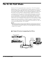
● A Simple XG System Incorporating the VL70-m
XG tone generator
PLAY EDIT
MUTE/
SOLO
PART
UTIL EFFECT
ENTER
SELECT
EXIT
VALUE
ALL
MIDI IN
INPUT
PHONES
XG
TG300B
C/M
DOC
POWER/VOL
PART
MIDI
BANK/PGM# VOL EXP PAN REV CHO VAR KEY
MODE
PERFORM
PUSH ON/OFF
Modem or
Printer port
MIDI controller
MIDI OUT
PS/V
RS-232C
MIDI IN
WX IN
MIDI OUT
TO HOST
BREATH
VIRTUAL ACOUSTIC TONE GENERATOR
PLAY EDIT
UTIL EFFECT
PHONES
BC/WX
VELOCITY
TOUCH EG
POWER/VOL
VOICE
VL-XG
PART
MIDI
BANK/PGM# VOL EXP PAN REV CHO VAR KEY
PUSH ON/OFF
VL70-m
36 The VL-XG PLAY Mode
MODE BREATH
MIDI/
WX
PART
ENTER
SELECT
EXIT
VALUE
ALL
Personal System/V
Personal System/V
IBM
Personal
computer
The VL-XG PLAY Main Control Mode
This mode is initially engaged when the VL-XG sound module mode is
selected. If the sub-control mode is active (see page 40), the main control
mode can be selected by simultaneously pressing the PART [-] and [+] buttons.
The VL-XG PLAY main control mode display looks like this:
PART
•
•
•
•
Part Number
Receive Channel
Bank Number
Program Number
• Volume
• Expression
MIDI
BANK/PGM
VOL
EXP PAN
REV
CHO
VAR KEY
•
•
•
•
•
Note Shift
Variation Send
Chorus Send
Reverb Send
Pan
The various parameters in this mode are selected via the SELECT [<] and [>]
buttons. The name of the currently selected parameter appears in the upper right
corner of the display (when the bank and program number parameters are
showing a solid triangular pointer indicates which of the two parameters is
selected). A small triangular pointer appears above the icon corresponding to the
selected parameter in the bottom line of the display. Once the desired parameter
has been selected, it’s value can be set as required via the VALUE [-] and [+]
buttons.
The VL-XG PLAY Mode 37
Rcv CH (Receive Channel)
Volume
Settings: 01 … 16, OFF
Settings: 000 … 127
Sets the MIDI receive channel on which the VL70m will receive data from your keyboard or other
controller. The receive channel must be set to the
same channel that the controlling device is transmitting on (“01” through “16”). When “OFF” is
selected, the VL70-m will not receive any data
from external MIDI devices.
Sets the volume of the current voice. The higher
the value the louder the volume.
Expresn (Expression)
Settings: 000 … 127
(Bank Number)
Settings: 112 … 119, Pr1, Pr2, Cst, Int
Sets the expression level of the current voice. The
higher the value the higher the expression level.
Pan
Settings: Rnd, L63 … C … R63
Selects the VL70-m voice bank: 112 through 119,
PRESET 1 (Pr1), PRESET 2 (Pr2), CUSTOM
(Cst), or INTERNAL (Int). See “Voice Organization” on page 26.
(Program Number)
Settings: 001 … 128
Selects the voice to played on the VL70-m. Banks
112 through 119 allow selection of voice numbers
from “022” to “128”, although some voice numbers are skipped since the VL70-m does not have a
full basic XG voice set. The PRESET 1 and
PRESET 2 banks each have voice numbers from
“001” to “128”, while the CUSTOM bank has
voice numbers from “001” to “006”, and the
INTERNAL bank has voice numbers from “001”
to “064”
38 The VL-XG PLAY Mode
Sets the pan position of the current voice — i.e.
the position of the voice between left and right in
the stereo sound field. A setting of “L63: sets the
pan position full left, “C” sets the pan at center,
and “R63” sets the pan full right. In between
settings produce corresponding intermediate pan
positions. The “Rnd” setting produces a randomlygenerated pan position.
RevSend (Reverb Send)
NoteSft (Note Shift)
Settings: 000 … 127
Settings: -24 … 0 … +24
Adjusts the level of the signal sent to the VL70-m
reverb effect stage. The higher the value, the
higher the level of the reverb send signal.
Transposes the pitch of the current voice down or
up in semitone steps over a ±2 octave range. “+00”
corresponds to standard pitch. Each increment
corresponds to a semitone. A setting of “-12”, for
example, transposes the pitch down one octave.
ChoSend (Chorus Send)
Settings: 000 … 127
Adjusts the level of the signal sent to the VL70-m
chorus effect stage. The higher the value, the
higher the level of the chorus send signal.
VarSend (Variation Send)
Settings: 000 … 127 (on, off when “INS”)
When the variation stage is connected as a system
effect (page 87), this parameter adjusts the level of
the signal sent to the VL70-m variation effect
stage. The higher the value, the higher the level of
the variation send signal. When the variation stage
is connected as an “insertion” effect (page 86), this
parameter turns variation send “on” or “off”.
The VL-XG PLAY Mode 39
The VL-XG PLAY Sub-control Mode
The sub control mode can be selected from the main control mode by
simultaneously pressing the PART [-] and [+] buttons. The VL-XG PLAY
sub-control mode display looks like this:
PART
• Device Number
• Master Volume
MIDI
BANK/PGM
VOL
EXP PAN
REV
CHO
VAR KEY
•
•
•
•
Transpose
Variation Return
Chorus Return
Reverb Return
• When you enter the VL-XG sub control mode from the
main control mode, “ALL” is automatically selected for the
“part” by simultaneously pressing the PART [-] and [+]
buttons (“ALL”).
The various parameters in this mode are selected via the SELECT [<] and [>]
buttons. The name of the currently selected parameter appears in the upper right
corner of the display. A small triangular pointer appears above the icon corresponding to the selected parameter in the bottom line of the display. Once the
desired parameter has been selected, it’s value can be set as required via the
VALUE [-] and [+] buttons.
40 The VL-XG PLAY Mode
DevNo. (Device Number)
ChoRtn (Chorus Return)
Settings: 001 … 016, all
Settings: 000 … 127
The Device Number parameter must be set properly when you want to transmit or receive MIDI
system exclusive data to or from another VL70-m
or other MIDI device (system exclusive data
includes voice parameters, system setup parameters, etc). The VL70-m Device number must be
set to the same number as the Device Number of
the external device. Select a device number from
“001” to “016”, or “all” . When “all” is selected,
MIDI system exclusive data can be received on all
device numbers, but transmission occurs via device
number 001.
Adjusts the level of the signal returned from the
VL70-m chorus effect stage. The higher the value,
the higher the level of the chorus signal.
M.Volum (Master Volume)
Settings: 000 … 127
VarRtn (Variation Return)
Settings: 000 … 127
Adjusts the level of the signal returned from the
VL70-m variation effect stage. The higher the
value, the higher the level of the variation signal.
This parameter is not available (“***” will appear
in place of the VarRtn value) when the variation
stage is connected as an “insertion” effect (page
86).
Trans (Transpose)
Sets the VL70-m master volume level. The higher
the value the louder the volume.
Settings: -24 … 0 … +24
RevRtn (Reverb Return)
Settings: 000 … 127
Adjusts the level of the signal returned from the
VL70-m reverb effect stage. The higher the value,
the higher the level of the reverb signal.
Transposes the pitch of the entire VL70-m system
(a single setting applies to all voices) down or up
in semitone steps over a ±2 octave range. “+00”
corresponds to standard pitch. Each increment
corresponds to a semitone. A setting of “-12”, for
example, transposes the pitch down one octave.
The VL-XG PLAY Mode 41
Controllers & Control Editing
If you’ve read the “Virtual Acoustic Synthesis” section (if you haven’t, please
do so — page 6) you should understand the concept of “controllers” as applied
to the VL70-m. The “controller parameters” correspond to simulated characteristics of the instrument model — e.g. breath pressure, embouchure or tonguing.
Any of these can be controlled by you via “physical controllers” — e.g. a breath
controller or modulation wheel — assigned to the required controller parameter.
Physical Controllers
• Breath Controller
• Foot Controller
• Etc.
"Physical controllers" such as
the Breath or Foot Controller
can be assigned to "controller
parameters" such as Pressure
or Embouchure.
VL Controller Parameters
• Pressure
• Embouchure
• Etc.
The effectiveness of the VL70-m as a musical instrument depends to a great
deal on how well you learn to use these controllers. Since the VL70-m sound is
produced by a computer-based physical model rather than a oscillator-based
tone generator, there are no hard-and-fast rules as to how any controller will
actually affect the sound. There are guidelines, based on the rule of the corresponding controller parameter within the physical model, but proficiency with
the VL70-m depends more on experience and practice — just as it does in any
acoustic instrument.
42 Controllers & Control Editing
● Physical Controllers
First, here’s a list of some of the physical controllers you might want to use
with the VL70-m:
Breath Controller A natural candidate for controlling pressure, tonguing, throat
(MIDI control
formant, growl, and other parameters.
change no. 02)
Pitch Bend Wheel The pitch bend wheel on your keyboard or other MIDI device
can be assigned to a range of parameters, but it’s “standard”
function is pitch control. A controller parameter such as Embouchure can also be assigned to the pitch bend wheel for more
realistic pitch variations.
Modulation
Wheel
(MIDI control
change no. 01)
Since the modulation wheel on your keyboard or other MIDI
device can be assigned to any controller parameter, it can be an
important tool for musical expression. Use it in conjunction with
a breath controller or a foot controller for broad expressive
variation.
Foot Controller
(MIDI control
change no. 04)
Like the modulation wheel, a foot controller connected to your
keyboard or other MIDI device can be assigned to any VL70-m
controller parameter.
Aftertouch
Keyboard aftertouch allows you to control any controller
parameter by the pressure you apply to a key after it is initially
pressed. This is perhaps the most “intimate” type of keyboard
expression control.
Velocity
Although normally assigned to pressure (particularly in plucked
string voices), keyboard velocity can also be assigned to any
other controller parameter.
Others
The MIDI protocol provides 119 control change numbers, some
of which are pre-assigned to specific controllers — as noted
above, “01” is “Modulation Wheel”, for example. 95 of these
are available for assignments to the VL70-m controller parameters, so any available MIDI control devices can be used to full
advantage. A complete list of the available MIDI control change
numbers is given below.
● MIDI Control Change Number Assignments
Control No.
Controller
off(00)
off (used by Bank Select MSB)
01
Modulation Wheel
02
Breath Controller
03
Unassigned
04
Foot Controller
05
Portamento Time
06
Data Entry MSB
07
Volume Control
08~09
Unassigned
10
Panpot
11
Expression
12~31
Unassigned
Controllers & Control Editing 43
44 Controllers & Control Editing
Control No.
Controller
off(32)
off (used by Bank Select LSB)
33~37
Unassigned
38
Data Entry LSB
39~63
Unassigned
64
Hold1
65
Portamento Switch
66
Unassigned
67
Soft Pedal
68~70
Unassigned
71
Harmonic Content
72
Release Time
73
Attack Time
74
Brightness
75~90
Unassigned
91
Effect Send Level (Reverb
Effect)
92
Unassigned
93
Effect Send Level 3 (Chorus
Effect)
94
Effect Send Level 4 (Variation
Effect)
95
Unassigned
AT
After Touch
VEL
Velocity
PB
Pitch Bend
● VL70-m Controller Parameters
Any of the physical controllers listed above can be assigned to control any of
the VL70-m’s controller parameters:
Pressure
The amount of breath pressure applied to a reed or mouthpiece,
or the speed of the bow applied to a string. Pressure variations
affect both volume and timbre.
Embouchure
The tightness of the lips against the reed or against each other.
In a string instrument voice Embouchure corresponds to how
strongly the bow is pressed against the string. Affects both pitch
and timbre.
Tonguing
Simulates the half-tonguing technique used by saxophone
players by changing the “slit” of the reed. The slit is the space
between the tip of the reed and the mouthpiece.
Amplitude
Unlike Pressure, this parameter simply controls the volume of
the sound without varying timbre.
Scream
Drives the entire system into chaotic oscillation, creating effects
that can only be achieved with physical modeling technology.
Breath Noise
Adds breath noise to produce exceptionally realistic effects with
many wind instruments.
Growl
A periodic pressure modulation which produces the “growl”
effect often heard in wind instruments.
Throat Formant
Controls the characteristics of the simulated player’s lungs,
trachea, and oral cavity. Can add a realistic “roughness” to the
sound. Throat formant only applies to some reed-type voices.
Filter
Similar to the dynamic filters found in many conventional
synthesizers, the cutoff frequency can be varied to produce a
wide range of timbral variations. Most voices use the low-pass
filter type, but some use the bandpass, high-pass, or band
eliminate types. Some voices use very little filter processing at
all. Changing the filter settings may not produce a particularly
noticeable effect. For detailed filter parameter programming use
the VL70-m Expert Editor software (page 25).
Harmonic
Enhancer
The Harmonic Enhancer can vary the harmonic structure of the
sound over a wide range. Since most VL70-m voices have
sufficient natural harmonic content, the Harmonic Enhancer is
actually only used on a few voices. Therefore changing the
controller destination with many voices will produce either no
change in the sound or a simple change in amplitude. For
detailed harmonic enhancer programming use the VL70-m
Expert Editor software (page 25).
Damping
Simulates the effect of damping due to losses within the body of
a wind instrument or in a string due to air friction. Affects both
pitch and timbre.
Absorption
Simulates the effect of high-frequency loss at the end of the air
column or string. In the case of a wind instrument, the Damping
and Absorption parameters control the diameter and shape of
the bell.
Controllers & Control Editing 45
Accessing & Editing the Control Parameters
The CONTROL EDIT mode can be accessed from the VOICE PLAY mode
as follows:
1. Press [EDIT]
Press the [EDIT] button to go to the VOICE EDIT sub-mode menu.
2. Select the CONTROL Sub-mode
Use the SELECT [<] and [>] buttons to select the CONTROL sub-mode, if
necessary. The icon to the left of “CONTROL” on the display will flash
when the CONTROL sub-mode is selected.
3. Press [ENTER]
Press the [ENTER] button to go to the CONTROL EDIT mode. “CONTROL
EDIT” will appear at the top of the display along with the number of the
currently selected control parameter.
4. Select a Parameter
Use the SELECT [<] and [>] buttons to select the parameter you want to
edit (see “The Control Edit Parameters”, below). The name of the currently
selected parameter and its current setting appear on the second line of the
display. An arrow to the left and/or right of the parameter name/value
indicates that the SELECT [<] and/or [>] buttons can be used to select
more parameters in the indicated direction.
5. Edit the Selected Parameter
Use the VALUE [-] and [+] buttons to set the value of the selected parameter
as required.
46 Controllers & Control Editing
6. Repeat As Necessary
Repeat steps 4 and 5 to edit as many parameters as required.
7. Exit When Done
Press ther [EXIT] button to return to the VOICE EDIT sub-mode menu, or
the [PLAY] button to return to the VOICE PLAY mode when you’re finished
editing.
■ IMPORTANT!
• If you want to keep the changes you made in the VOICE EDIT mode, be sure to store the
edited voice to an appropriate INTERNAL voice number before selecting a new voice. All
edited data will be lost if you select a new voice before storing the edited voice!
Controllers & Control Editing 47
The Control Edit Parameters
Please note that a number of CONTROL EDIT parameters which are available in the VOICE sound module mode are not available in the VL-XG
sound module mode (page 28). The parameter numbers are therefore different in
each mode. Some of the value ranges are also different — the differences will
be listed with the actual parameter descriptions.
● VOICE Sound Module Mode Control Edit Parameters
Refer to the page numbers listed for full details on each parameter.
Pitch Bend ........................................................................................ 52
01: PB Ctrl (Pitch Bend Control)
02: PB LowCtrl (Pitch Bend Low Control)
03: PBLFO PMod (Pitch Bend LFO Pitch Modulation)
Modulation Wheel .......................................................................... 53
04: MWLFO PMod (Modulation Wheel LFO Pitch Modulation)
05: MWLFO FMod (Modulation Wheel LFO Filter Modulation)
Aftertouch ....................................................................................... 53
06: ATFil Ctrl (Aftertouch Filter Control)
07: ATLFO PMod (Aftertouch LFO Pitch Modulation)
Assignable Controller ..................................................................... 54
08: AC1 CC No. (Assignable Controller 1 Control Change Number)
09: AC1FilCtrl (Assignable Controller 1 Filter Control)
10: AC1AmpCtrl (Assignable Controller 1 Amplitude Control)
11: AC1LFOPMod (Assignable Controller 1 LFO Pitch Modulation)
Expression ........................................................................................ 54
12: Exp Mode (Expression Mode)
Pressure ............................................................................................ 55
13: Prs CC No. (Pressure Control Change Number)
14: PrsCtrlDpt (Pressure Control Depth)
15: Prs Curve (Pressure Curve)
Filter
.............................................................................................. 55
16: Fil CC No. (Filter Control Change Number)
17: FilCtrlDpt (Filter Control Depth)
18: Fil Curve (Filter Curve)
Amplitude ........................................................................................ 56
19: Amp CC No. (Amplitude Control Change Number)
20: AmpCtrlDpt (Amplitude Control Depth)
21: Amp Curve (Amplitude Curve)
48 Controllers & Control Editing
Embouchure ..................................................................................... 57
22: Emb CC No. (Embouchure Control Change Number)
23: EmbUpprDpt (Embouchure Upper Control Depth)
24: EmbLowrDpt (Embouchure Lower Control Depth)
25: Emb Mode (Embouchure Mode)
Tonguing .......................................................................................... 58
26: Tng CC No. (Tonguing Control Change Number)
27: TngCtrlDpt (Tonguing Control Depth)
28: Tng Curve (Tonguing Curve)
Scream .............................................................................................. 59
29: Scr CC No. (Scream Control Change Number)
30: ScrCtrlDpt (Scream Control Depth)
31: Scr Curve (Scream Curve)
Breath Noise .................................................................................... 60
32: Bnz CC No. (Breath Noise Control Change Number)
33: BnzCtrlDpt (Breath Noise Control Depth)
34: Bnz Curve (Breath Noise Curve)
Growl .............................................................................................. 61
35: Grl CC No. (Growl Control Change Number)
36: GrlCtrlDpt (Growl Control Depth)
37: Grl Curve (Growl Curve)
Throat Formant ............................................................................... 62
38: Thr CC No. (Throat Formant Control Change Number)
39: ThrCtrlDpt (Throat Formant Control Depth)
40: Thr Curve (Throat Formant Curve)
Harmonic Enhancer ......................................................................... 62
41: Hrm CC No. (Harmonic Enhancer Control Change Number)
42: HrmCtrlDpt (Harmonic Enhancer Control Depth)
43: Hrm Curve (Harmonic Enhancer Curve)
Damping .......................................................................................... 63
44: Dmp CC No. (Damping Control Change Number)
45: DmpCtrlDpt (Damping Control Depth)
46: Dmp Curve (Damping Curve)
Absorption ....................................................................................... 64
47: Abs CC No. (Apsorption Control Change Number)
48: AbsCtrlDpt (Absorption Control Depth)
49: Abs Curve (Absorption Curve)
Controllers & Control Editing 49
● VL-XG Sound Module Mode Control Edit Parameters
Refer to the page numbers listed for full details on each parameter.
Pitch Bend ........................................................................................ 52
01: PB Ctrl (Pitch Bend Control)
02: PB LowCtrl (Pitch Bend Low Control)
03: PBLFO PMod (Pitch Bend LFO Pitch Modulation)
Modulation Wheel .......................................................................... 53
04: MWLFO PMod (Modulation Wheel LFO Pitch Modulation)
05: MWLFO FMod (Modulation Wheel LFO Filter Modulation)
Aftertouch ....................................................................................... 53
06: ATFil Ctrl (Aftertouch Filter Control)
07: ATLFO PMod (Aftertouch LFO Pitch Modulation)
Assignable Controller ..................................................................... 54
08: AC1 CC No. (Assignable Controller 1 Control Change Number)
09: AC1FilCtrl (Assignable Controller 1 Filter Control)
10: AC1AmpCtrl (Assignable Controller 1 Amplitude Control)
11: AC1LFOPMod (Assignable Controller 1 LFO Pitch Modulation)
Pressure ............................................................................................ 55
12: Prs CC No. (Pressure Control Change Number)
13: PrsCtrlDpt (Pressure Control Depth)
Embouchure ..................................................................................... 57
14: Emb CC No. (Embouchure Control Change Number)
15: EmbCtrlDpt (Embouchure Control Depth)
Tonguing .......................................................................................... 58
16: Tng CC No. (Tonguing Control Change Number)
17: TngCtrlDpt (Tonguing Control Depth)
Scream .............................................................................................. 59
18: Scr CC No. (Scream Control Change Number)
19: ScrCtrlDpt (Scream Control Depth)
Breath Noise .................................................................................... 60
20: Bnz CC No. (Breath Noise Control Change Number)
21: BnzCtrlDpt (Breath Noise Control Depth)
Growl .............................................................................................. 61
22: Grl CC No. (Growl Control Change Number)
23: GrlCtrlDpt (Growl Control Depth)
50 Controllers & Control Editing
Throat Formant ............................................................................... 62
24: Thr CC No. (Throat Formant Control Change Number)
25: ThrCtrlDpt (Throat Formant Control Depth)
Harmonic Enhancer ......................................................................... 62
26: Hrm CC No. (Harmonic Enhancer Control Change Number)
27: HrmCtrlDpt (Harmonic Enhancer Control Depth)
Damping .......................................................................................... 63
28: Dmp CC No. (Damping Control Change Number)
29: DmpCtrlDpt (Damping Control Depth)
Absorption ....................................................................................... 64
30: Abs CC No. (Apsorption Control Change Number)
31: AbsCtrlDpt (Absorption Control Depth)
Controllers & Control Editing 51
● Control Edit Parameter Descriptions
The small parameter numbers in parentheses apply in the VL-XG sound module mode.
Pitch Bend
01(01): PB Ctrl
02(02): PB LowCtrl
• Pitch Bend Low Control
• Settings: -24 … +24
• Pitch Bend Control
• Settings: -24 … +24
This parameter sets the maximum amount of pitch
bend which will occur when the pitch controller is
set to its maximum position (e.g. when the pitch
bend wheel on a keyboard is rolled all the way up).
Minus setting produce a downward pitch bend.
Each increment corresponds to a semitone. A
setting of “+12”, for example, results in maximum
upward pitch bend of one octave.
• This setting automaically switches the plus/
minus status of the “PB LowCtrl” parameter,
below: If “PB Ctrl” is set to a “+” value, “PB
LowCtrl” is automatically switched to a “-”
value, and vice-versa.
• Natural acoustic musical instruments have no
“pitch parameter”. Pitch is determined by the
properties of the instrument’s resonant body as
well as the condition of the instrument’s driver.
The same applies to Virtual Acoustic Synthesis:
in the VL70-m pitch bend is simulated by
manipulating the appropriate pipe/string length
and driver characteristics. As a result, the pitch
bend range may not always be “mathematically” accurate.
52 Controllers & Control Editing
“PB LowCtrl” sets the maximum amount of pitch
bend which will occur when the pitch controller is
set to its lowest position (e.g. when the pitch bend
wheel on a keyboard is rolled all the way down).
Plus settings produce an upward pitch bend. Each
increment corresponds to a semitone. A setting of
“-12”, for example, results in maximum downward
pitch bend of one octave.
03(03): PBLFO PMod
• Pitch Bend LFO Pitch Modulation
• Settings: 000 … 127
Sets the amount of LFO pitch modulation applied
by the pitch controller (e.g. the pitch bend wheel
on a keyboard). The higher the value the greater
the amount of pitch modulation produced by pitch
controller operation. A setting of “000” produces
no pitch modulation.
• In the VL70-m pitch modulation produces
extremely realistic vibrato effects by simultaneously modulating the pitch, embouchure, and
pressure parameters.
Modulation Wheel
04(04): MWLFO PMod
• Modulation Wheel LFO Pitch Modulation
• Settings: 000 … 127
Sets the amount of LFO pitch modulation applied
by the modulation controller (e.g. the modulation
wheel on a keyboard — MIDI control change
number 01). The higher the value the greater the
amount of pitch modulation produced by modulation controller operation. A setting of “000”
produces no pitch modulation.
Aftertouch
06(06): ATFil Ctrl
• Aftertouch Filter Control
• Settings: -64 … +63
Determines the degree to which the filter is
affected by keyboard aftertouch. Plus settings
cause the cutoff frequency of the filter to increase
in response to increasing aftertouch pressure, while
minus values cause the filter frequency to decrease
in response to increasing aftertouch pressure.
07(07): ATLFO PMod
05(05): MWLFO FMod
• Modulation Wheel LFO Filter Modulation
• Settings: 000 … 127
Sets the amount of LFO filter cutoff frequency
modulation applied by the modulation controller
(e.g. the modulation wheel on a keyboard — MIDI
control change number 01). The higher the value
the greater the amount of filter modulation produced by modulation controller operation. A setting
of “000” produces no filter modulation.
• Aftertouch LFO Pitch Modulation
• Settings: 000 … 127
Sets the amount of LFO pitch modulation applied
by keyboard aftertouch. The higher the value the
greater the amount of pitch modulation produced
by aftertouch pressure. A setting of “000” produces
no pitch modulation.
Controllers & Control Editing 53
Assignable Controller
08(08): AC1 CC No.
• Assignable Controller 1 Control Change Number
• Settings: off … 95
amplitude to increase in response to increasing
controller values, while minus values cause the
amplitude to decrease in response to increasing
controller values.
11(11): AC1LFOPMod
• Assignable Controller 1 LFO Pitch Modulation
• Settings: 000 … 127
Assigns the specified control change number as
“Assignable Controller 1”. The assigned controller
can then be used to control filter, amplitude, and/or
pitch modulation as specified by the “AC1FilCtrl”,
AC1AmpCtrl, and “AC1LFOPMod” parameters.
below. For example, if this parameter is set to “04”
(Foot Controller), then a MIDI foot controller can
be used to control any of the parameters just
mentioned.
Sets the amount of LFO pitch modulation applied
by Assignable Controller 1 (see “AC1 CC No.”,
above). The higher the value the greater the
amount of pitch modulation produced by the
controller. A setting of “000” produces no pitch
modulation.
09(09): AC1FilCtrl
• Assignable Controller 1 Filter Control
• Settings: -64 … +63
Expression
12: Exp Mode (VOICE mode only)
• Expression Mode
• Settings: BC, Vol
Determines the degree to which the filter is
affected by Assignable Controller 1 (see “AC1 CC
No.”, above). Plus settings cause the cutoff frequency of the filter to increase in response to
increasing controller values, while minus values
cause the filter frequency to decrease in response
to increasing controller values.
10(10): AC1AmpCtrl
• Assignable Controller 1 Amplitude Control
• Settings: -64 … +63
Determines the degree to which amplitude (volume) is affected by Assignable Controller 1 (see
“AC1 CC No.”, above). Plus settings cause the
54 Controllers & Control Editing
Determines whether expression control (MIDI
control change number 11) will function as volume
control or as breath controller. When set to “Vol”
expression will affect volume, but when set to
“BC” expression will produce the same effect as a
breath controller connected to the VL70-m
BREATH jack, affecting the same breath-controlled
parameters.
Pressure
13(12): Prs CC No.
15: Prs Curve (VOICE mode only)
• Pressure Curve
• Settings: -16 … +16
• Pressure Control Change Number
• Settings: off… 95, AT, VEL, PB
“Pressure” corresponds to the amount of breath
pressure applied to a reed or mouthpiece, or the
speed of the bow applied to a string. Pressure
variations affect both volume and timbre. The “Prs
CC No.” parameter specifies the controller to be
used for pressure control. When set to “off”
maximum pressure is applied at all times.
• Please note that pressure affects not only
volume, but timbre and pitch as well. Accurate
keyboard/controller pitch is produced only at
maximum pressure.
• The “PrsCtrlDpt” parameter, below, must be set
to an appropriate value (higher than “+01” or
lower than “-01”) for pressure control to have
any effect.
Determines the relationship between the controller
value and pressure. When set to “+00” the relationship is linear. That is, a change in the controller
value produces a corresponding change in pressure.
As the curve value increases the lower end of the
controller range has relatively little effect on the
sound while higher controller values produce more
dramatic changes. Negative curve values have the
opposite effect: the sound changes dramatically at
low controller values while higher values produce
relatively little effect. The “Curve” setting is
reflected in the graph at the bottom of the display
— the horizontal axis represents the controller
value and the vertical axis represents pressure.
14(13): PrsCtrlDpt
• Pressure Control Depth
• Settings: -127 … +127 (VL-XG Mode: -64 … +63)
Filter
16: Fil CC No. (VOICE mode only)
• Filter Control Change Number
• Settings: off… 95, AT, VEL, PB
Sets the amount of variation produced by the
controller assigned to pressure. The higher the
value the greater the variation. Positive values
cause an increase in pressure in response to higher
controller values (e.g. increased breath pressure or
higher modulation wheel position), while minus
values cause a decrease in pressure in response to
higher controller values. The “Depth” setting is
reflected in the graph at the bottom of the display
— the horizontal axis represents the controller
value and the vertical axis represents pressure.
• Set this parameter to “+00” if do not intend to
control pressure via a controller.
The “Fil CC No.” parameter specifies the controller to be used for filter cutoff frequency control
(page 45). When set to “off” no filter frequency
variation can be applied via a controller.
• The “FilCtrlDpt” parameter, below, must be set
to an appropriate value (higher than “+01” or
lower than “-01”) for filter control to have any
effect.
• Most voices use the low-pass filter type, but
some use the bandpass, high-pass, or band
Controllers & Control Editing 55
eliminate types. Some voices use very little
filter processing at all. Changing the filter
settings may not produce a particularly noticeable effect. For detailed filter parameter programming use the VL70-m Expert Editor
software (page 25).
17: FilCtrlDpt (VOICE mode only)
• Filter Control Depth
• Settings: -127 … +127
relatively little effect on the sound while higher
controller values produce more dramatic changes.
Negative curve values have the opposite effect: the
sound changes dramatically at low controller
values while higher values produce relatively little
effect. The “Curve” setting is reflected in the graph
at the bottom of the display — the horizontal axis
represents the controller value and the vertical axis
represents filter cutoff frequency.
Amplitude
Sets the amount of variation produced by the
controller assigned to dynamic filter. The higher
the value the greater the variation. Positive values
cause an increase in filter cutoff frequency in
response to higher controller values (e.g. increased
breath pressure or higher modulation wheel
position), while minus values cause a decrease in
filter cutoff frequency in response to higher
controller values. The “Depth” setting is reflected
in the graph at the bottom of the display — the
horizontal axis represents the controller value and
the vertical axis represents filter cutoff frequency.
• The effect of the filter may be barely noticeable
on some voices. In some cases it may be
necessary to lower the cutoff frequency to
produce the desired effect.
18: Fil Curve (VOICE mode only)
• Filter Curve
• Settings: -16 … +16
19: Amp CC No. (VOICE mode only)
• Amplitude Control Change Number
• Settings: off… 95, AT, VEL, PB
Unlike pressure, “Amplitude” controls the volume
of the sound without varying timbre or pitch. The
“Amp CC No.” parameter specifies the controller
to be used for amplitude control. When set to “off”
maximum volume is produced at all times.
• The “AmpCtrlDpt” parameter, below, must be
set to an appropriate value (higher than “+01”
or lower than “-01”) for amplitude control to
have any effect.
20: AmpCtrlDpt (VOICE mode only)
• Amplitude Control Depth
• Settings: -127 … +127
Determines the relationship between the controller
value and dynamic filter cutoff frequency. When
set to “+00” the relationship is linear. That is, a
change in the controller value produces a corresponding change in frequency. As the curve value
increases the lower end of the controller range has
56 Controllers & Control Editing
Sets the amount of variation produced by the
controller assigned to amplitude. The higher the
value the greater the variation. Positive values
cause an increase in amplitude in response to
higher controller values (e.g. increased breath
pressure or higher modulation wheel position),
while minus values cause a decrease in amplitude
in response to higher controller values. The
“Depth” setting is reflected in the graph at the
bottom of the display — the horizontal axis
represents the controller value and the vertical axis
represents amplitude.
21: Amp Curve (VOICE mode only)
• Amplitude Curve
• Settings: -16 … +16
Determines the relationship between the controller
value and amplitude. When set to “+00” the
relationship is linear. That is, a change in the
controller value produces a corresponding change
in amplitude. As the curve value increases the
lower end of the controller range has relatively
little effect on the sound while higher controller
values produce more dramatic changes. Negative
curve values have the opposite effect: the sound
changes dramatically at low controller values while
higher values produce relatively little effect. The
“Curve” setting is reflected in the graph at the
bottom of the display — the horizontal axis
represents the controller value and the vertical axis
represents amplitude.
Embouchure
22(14): Emb CC No.
• Embouchure Control Change Number
• Settings: off… 95, AT, VEL, PB
“Embouchure” corresponds to the tightness of the
lips against the reed or against each other. In a
string instrument voice embouchure corresponds to
how strongly the bow is pressed against the string.
Affects both pitch and timbre. The “Emp CC No.”
parameter specifies the controller to be used for
embouchure control. When set to “off” medium
embouchure is applied at all times.
• Please note that with many voices accurate
keyboard/controller pitch is produced only at
medium embouchure.
• The “EmbUpprDpt” and “EmbLowrDpt”
parameters, below, must be set to appropriate
values (higher than “+01” or lower than “-01”)
for embouchure control to have any effect.
23: EmbUpprDpt (VOICE mode only)
• Embouchure Upper Control Depth
• Settings: -127 … +127
Sets the amount of variation produced by the
controller assigned to embouchure when the
controller is set to its maximum position (e.g. a
modulation wheel rolled all the way up). The
higher the value the greater the variation. Positive
values cause an increase in embouchure in response to higher controller values, while minus
values cause a decrease in embouchure in response
to higher controller values.
Controllers & Control Editing 57
24: EmbLowrDpt (VOICE mode only)
25: Emb Mode (VOICE mode only)
• Embouchure Lower Control Depth
• Settings: -127 … +127
• Embouchure Mode
• Settings: Cntr, Min
Sets the amount of variation produced by the
controller assigned to embouchure when the
controller is set to it minimum position (e.g. a
modulation wheel rolled all the way down). The
higher the value the greater the variation. Positive
values cause an increase in embouchure in response to lower controller values, while minus
values cause a decrease in embouchure in response
to lower controller values. The “EmbLowrDpt”
parameter has no effect when the “Emb Mode”
parameter, below, is set to “Min”.
Selects the controller value (position) which will
produce “normal” embouchure. When set to “Cntr”
(Center) a central controller position will produce
normal embouchure, allowing both downward and
upward variation. A setting of “Min” (Minimum)
will produce normal embouchure when the controller is set to its minimum position, allowing only
upward variation.
● VL-XG MODE
In the VL-XG sound module mode (page 28)
the “EmbUpprDpt” and EmbLowrDpt”
parameters are replaced by a single
“EmbCtrlDpt” parameter, as follows:
Tonguing
26(16): Tng CC No.
• Tonguing Control Change Number
• Settings: off … 95, AT, VEL, PB
15: EmbCtrlDpt
• Embouchure Control Depth
• Settings: -64 … +63
Sets the amount of variation produced by the
controller assigned to embouchure. The
higher the value the greater the variation.
Positive values cause an increase in embouchure in response to higher controller values
(e.g. increased breath pressure or higher
modulation wheel position), while minus
values cause an decrease in embouchure in
response to higher controller values.
58 Controllers & Control Editing
“Tonguing” simulates the half-tonguing technique
used by saxophone players by changing the “slit”
of the reed. The slit is the space between the tip of
the reed and the mouthpiece. The “Tng CC No.”
parameter specifies the controller to be used for
tonguing control. When set to “off” no tonguing is
applied.
• Please note that accurate keyboard pitch is
produced only when maximum tonguing is
applied or the tonguing controller is turned off.
• The “TngCtrlDpt” parameter, below, must be
set to an appropriate value (higher than “+01”
or lower than “-01”) for tonguing control to
have any effect.
27(17): TngCtrlDpt
• Tonguing Control Depth
• Settings: -127 … +127 (VL-XG Mode: -64 … +63)
Scream
29(18): Scr CC No.
• Scream Control Change Number
• Settings: off … 95, AT, VEL, PB
Sets the amount of variation produced by the
controller assigned to tonguing. The higher the
value the greater the variation. Positive values
cause an decrease in tonguing in response to higher
controller values (e.g. increased breath pressure or
higher modulation wheel position), while minus
values cause an increase in tonguing in response to
higher controller values. The “Depth” setting is
reflected in the graph at the bottom of the display
— the horizontal axis represents the controller
value and the vertical axis represents tonguing.
28: Tng Curve (VOICE mode only)
• Tonguing Curve
• Settings: -16 … +16
“Scream” drives the entire system into chaotic
oscillation, creating effects that can only be
achieved with physical modeling technology. The
“Scr CC No.” parameter specifies the controller to
be used for scream control. When set to “off”, no
scream variation can be produced via a controller,
but a continuous scream value is determined by the
“30(19): ScrCtrlDpt” parameter, below (negative
values increase the scream level).
• The “ScrCtrlDpt” parameter, below, must be set
to an appropriate value (higher than “+01” or
lower than “-01”) for scream control to have
any effect.
30(19): ScrCtrlDpt
• Scream Control Depth
• Settings: -127 … +127 (VL-XG Mode: -64 … +63)
Determines the relationship between the controller
value and tonguing. When set to “+00” the relationship is linear. That is, a change in the controller
value produces a corresponding change in tonguing. As the curve value increases the lower end of
the controller range has relatively little effect on
the sound while higher controller values produce
more dramatic changes. Negative curve values
have the opposite effect: the sound changes
dramatically at low controller values while higher
values produce relatively little effect. The “Curve”
setting is reflected in the graph at the bottom of the
display — the horizontal axis represents the
controller value and the vertical axis represents
tonguing.
Sets the amount of variation produced by the
controller assigned to scream. The higher the value
the greater the variation. Positive values cause an
increase in scream effect in response to higher
controller values (e.g. increased breath pressure or
higher modulation wheel position), while minus
values cause a decrease in scream effect in response to higher controller values. The “Depth”
setting is reflected in the graph at the bottom of the
display — the horizontal axis represents the
controller value and the vertical axis represents
scream.
Controllers & Control Editing 59
31: Scr Curve (VOICE mode only)
• Scream Curve
• Settings: -16 … +16
•
The “BnzCtrlDpt” parameter, below, must be
set to an appropriate value (higher than “+01”
ro lower than “-01”) for breath noise control to
have any effect.
33(21): BnzCtrlDpt
• Breath Noise Control Depth
• Settings: -127 … +127 (VL-XG Mode: -64 … +63)
Determines the relationship between the controller
value and scream. When set to “+00” the relationship is linear. That is, a change in the controller
value produces a corresponding change in scream
effect. As the curve value increases the lower end
of the controller range has relatively little effect on
the sound while higher controller values produce
more dramatic changes. Negative curve values
have the opposite effect: the sound changes
dramatically at low controller values while higher
values produce relatively little effect. The “Curve”
setting is reflected in the graph at the bottom of the
display — the horizontal axis represents the
controller value and the vertical axis represents
scream.
Sets the amount of variation produced by the
controller assigned to breath noise. The higher the
value the greater the variation. Positive values
cause an increase in breath noise in response to
higher controller values (e.g. increased breath
pressure or higher modulation wheel position),
while minus values cause a decrease in breath
noise in response to higher controller values. The
“Depth” setting is reflected in the graph at the
bottom of the display — the horizontal axis
represents the controller value and the vertical axis
represents breath noise.
34: Bnz Curve (VOICE mode only)
Breath Noise
• Breath Noise Curve
• Settings: -16 … +16
32(20): Bnz CC No.
• Breath Noise Control Change Number
• Settings: off… 95, AT, VEL, PB
“Breath Noise” can be used to add the required
amount of breath noise to a voice. The “Bnz CC
No.” parameter specifies the controller to be used
for breath noise control. When set to “off”, no
breath noise variation can be produced via a
controller, but a continuous breath noise value is
determined by the “33(21): BnzCtrlDpt” parameter,
below (negative values increase the breath noise
level).
60 Controllers & Control Editing
Determines the relationship between the controller
value and breath noise. When set to “+00” the
relationship is linear. That is, a change in the
controller value produces a corresponding change
in breath noise. As the curve value increases the
lower end of the controller range has relatively
little effect on the sound while higher controller
values produce more dramatic changes. Negative
curve values have the opposite effect: the sound
changes dramatically at low controller values while
higher values produce relatively little effect. The
“Curve” setting is reflected in the graph at the
bottom of the display — the horizontal axis
represents the controller value and the vertical axis
represents breath noise.
• The amount of breath noise produced also
depends on pressure, so the breath noise curve
indicated by the graph at the bottom of the
display may not always accurately reflect the
perceived curve.
Sets the amount of variation produced by the
controller assigned to growl. The higher the value
the greater the variation. Positive values cause an
increase in growl effect in response to higher
controller values (e.g. increased breath pressure or
higher modulation wheel position), while minus
values cause a decrease in growl effect in response
to higher controller values. The “Depth” setting is
reflected in the graph at the bottom of the display
— the horizontal axis represents the controller
value and the vertical axis represents growl.
37: Grl Curve (VOICE mode only)
Growl
• Growl Curve
• Settings: -16 … +16
35(22): Grl CC No.
• Growl Control Change Number
• Settings: off… 95, AT, VEL, PB
“Growl” produces a periodic pressure modulation
which produces the “growl” effect often heard in
wind instruments. The “Grl CC No.” parameter
specifies the controller to be used for growl
control. When set to “off”, no growl variation can
be produced via a controller, but a continuous
growl value is determined by the “36(23):
GrlCtrlDpt” parameter, below (negative values
increase the growl level).
• The “GrlCtrlDpt” parameter, below, must be set
to an appropriate value (higher than “+01” or
lower than “-01”) for growl control to have any
effect.
Determines the relationship between the controller
value and growl. When set to “+00” the relationship is linear. That is, a change in the controller
value produces a corresponding change in growl.
As the curve value increases the lower end of the
controller range has relatively little effect on the
sound while higher controller values produce more
dramatic changes. Negative curve values have the
opposite effect: the sound changes dramatically at
low controller values while higher values produce
relatively little effect. The “Curve” setting is
reflected in the graph at the bottom of the display
— the horizontal axis represents the controller
value and the vertical axis represents growl.
36(23): GrlCtrlDpt
• Growl Control Depth
• Settings: -127 … +127 (VL-XG Mode: -64 … +63)
Controllers & Control Editing 61
Throat Formant
38(24): Thr CC No.
40: Thr Curve (VOICE mode only)
• Throat Formant Curve
• Settings: -16 … +16
• Throat Formant Control Change Number
• Settings: off… 95, AT, VEL, PB
“Throat Formant” controls the characteristics of
the simulated player’s lungs, trachea, and oral
cavity. Can add a realistic “roughness” to the
sound. The “Thr CC No.” parameter specifies the
controller to be used for throat formant control.
When set to “off”, no throat formant variation can
be produced via a controller, but a continuous
throat formant value is determined by the “39(25):
ThrCtrlDpt” parameter, below (negative values
increase the throat formant level).
• The “ThrCtrlDpt” parameter, below, must be set
to an appropriate value (higher than “+01” or
lower than “-01”) for throat formant control to
have any effect.
• Throat Formant only applies to some reed-type
voices.
Determines the relationship between the controller
value and throat formant depth. When set to “+00”
the relationship is linear. That is, a change in the
controller value produces a corresponding change
in throat formant depth. As the curve value increases the lower end of the controller range has
relatively little effect on the sound while higher
controller values produce more dramatic changes.
Negative curve values have the opposite effect: the
sound changes dramatically at low controller
values while higher values produce relatively little
effect. The “Curve” setting is reflected in the graph
at the bottom of the display — the horizontal axis
represents the controller value and the vertical axis
represents throat formant depth.
39(25): ThrCtrlDpt
• Throat Formant Control Depth
• Settings: -127 … +127 (VL-XG Mode: -64 … +63)
Harmonic Enhancer
41(26): Hrm CC No.
• Harmonic Enhancer Control Change Number
• Settings: off … 95, AT, VEL, PB
Sets the amount of variation produced by the
controller assigned to throat formant. The higher
the value the greater the variation. Positive values
cause an increase in throat formant effect in
response to higher controller values (e.g. increased
breath pressure or higher modulation wheel
position), while minus values cause a decrease in
throat formant effect in response to higher controller values. The “Depth” setting is reflected in the
graph at the bottom of the display — the horizontal
axis represents the controller value and the vertical
axis represents throat formant depth.
62 Controllers & Control Editing
The Harmonic Enhancer can vary the harmonic
structure of the sound over a wide range. The
“Hrm CC No.” parameter specifies the controller to
be used for harmonic enhancer depth (wet/dry
balance) control. When set to “off” no harmonic
enhancer depth variation can be applied via a
controller.
• The “HrmCtrlDpt” parameter, below, must be
set to an appropriate value (higher than “+01”
•
or lower than “-01”) for harmonic enhancer
control to have any effect.
Since most VL70-m voices have sufficient
natural harmonic content, the Harmonic Enhancer is actually only used on a few voices.
Therefore changing the controller destination
with many voices will produce either no change
in the sound or a simple change in amplitude.
For detailed harmonic enhancer programming
use the VL70-m Expert Editor software (page
25).
change in harmonic enhancer depth. As the curve
value increases the lower end of the controller
range has relatively little effect on the sound while
higher controller values produce more dramatic
changes. Negative curve values have the opposite
effect: the sound changes dramatically at low
controller values while higher values produce
relatively little effect. The “Curve” setting is
reflected in the graph at the bottom of the display
— the horizontal axis represents the controller
value and the vertical axis represents harmonic
enhancer depth.
42(27): HrmCtrlDpt
• Harmonic Enhancer Control Depth
• Settings: -127 … +127 (VL-XG Mode: -64 … +63)
Damping
44(28): Dmp CC No.
Sets the amount of variation produced by the
controller assigned to the harmonic enhancer. The
higher the value the greater the variation. Positive
values cause an increase in harmonic enhancer
depth in response to higher controller values (e.g.
increased breath pressure or higher modulation
wheel position), while minus values cause a
decrease in harmonic enhancer depth in response to
higher controller values. The “Depth” setting is
reflected in the graph at the bottom of the display
— the horizontal axis represents the controller
value and the vertical axis represents harmonic
enhancer depth .
43: Hrm Curve (VOICE mode only)
• Harmonic Enhancer Curve
• Settings: -16 … +16
• Damping Control Change Number
• Settings: off… 95, AT, VEL, PB
“Damping” simulates the effect of damping due to
losses within the body of a wind instrument or in a
string due to air friction. Affects both pitch and
timbre. The “Dmp CC No.” parameter specifies the
controller to be used for damping control. When
set to “off” no damping variation can be applied
via a controller.
• Please note that accurate keyboard pitch is
produced only when damping is maximum.
• The “DmpCtrlDpt” parameter, below, must be
set to an appropriate value (higher than “+01”
or lower than “-01”) for damping control to
have any effect.
45(29): DmpCtrlDpt
Determines the relationship between the controller
value and harmonic enhancer depth. When set to
“+00” the relationship is linear. That is, a change
in the controller value produces a corresponding
• Damping Control Depth
• Settings: -127 … +127 (VL-XG Mode: -64 … +63)
Controllers & Control Editing 63
Sets the amount of variation produced by the
controller assigned to damping. The higher the
value the greater the variation. Positive values
cause a decrease in damping in response to higher
controller values (e.g. increased breath pressure or
higher modulation wheel position), while minus
values cause an increase in damping in response to
higher controller values. The “Depth” setting is
reflected in the graph at the bottom of the display
— the horizontal axis represents the controller
value and the vertical axis represents damping.
46: Dmp Curve (VOICE mode only)
• Damping Curve
• Settings: -16 … +16
Determines the relationship between the controller
value and damping. When set to “+00” the relationship is linear. That is, a change in the controller
value produces a corresponding change in damping. As the curve value increases the lower end of
the controller range has relatively little effect on
the sound while higher controller values produce
more dramatic changes. Negative curve values
have the opposite effect: the sound changes
dramatically at low controller values while higher
values produce relatively little effect. The “Curve”
setting is reflected in the graph at the bottom of the
display — the horizontal axis represents the
controller value and the vertical axis represents
damping.
64 Controllers & Control Editing
Absorption
47(30): Abs CC No.
• Absorption Control Change Number
• Settings: off … 95, AT, VEL, PB
“Absorption” simulates the effect of high-frequency loss at the end of the air column or string.
The “Abs CC No.” parameter specifies the controller to be used for absorption control. When set to
“off” no absorption variation can be applied via a
controller.
• Please note that accurate keyboard pitch is
produced only at when absorption is maximum.
• The “AbsCtrlDpt” parameter, below, must be
set to an appropriate value (higher than “+01”
or lower than “-01”) for absorption control to
have any effect.
48(31): AbsCtrlDpt
• Absorption Control Depth
• Settings: -127 … +127 (VL-XG Mode: -64 … +63)
Sets the amount of variation produced by the
controller assigned to absorption. The higher the
value the greater the variation. Positive values
cause a decrease in absorption in response to
higher controller values (e.g. increased breath
pressure or higher modulation wheel position),
while minus values cause an increase in absorption
in response to higher controller values. The
“Depth” setting is reflected in the graph at the
bottom of the display — the horizontal axis
represents the controller value and the vertical axis
represents absorption.
49: Abs Curve (VOICE mode only)
• Absorption Curve
• Settings: -16 … +16
Determines the relationship between the controller
value and absoprtion. When set to “+00” the
relationship is linear. That is, a change in the
controller value produces a corresponding change
in absorption. As the curve value increases the
lower end of the controller range has relatively
little effect on the sound while higher controller
values produce more dramatic changes. Negative
curve values have the opposite effect: the sound
changes dramatically at low controller values while
higher values produce relatively little effect. The
“Curve” setting is reflected in the graph at the
bottom of the display — the horizontal axis
represents the controller value and the vertical axis
represents absorption.
• Absorption control can have a significant effect
on pitch.
Controllers & Control Editing 65
Filter & Envelope Generator Editing
The VL70-m has two envelope generators which can be independently programmed to produce time-based variations in the sound.
● Amplitude & Filter EG
The Amplitude & Filter Envelope Generator controls both the amplitude of the
sound and the cutoff frequency of the VL70-m filter from note attack to release.
This envelope generator has three parameters which can be edited via the VL70m panel: attack time, decay time, and release time. Amplitude control defines
the basic “shape” of the notes produced, while filter control makes it possible to
create a variety of dynamic timbral sweeps.
■ NOTES
• Most voices use the low-pass filter type, but some use the bandpass, high-pass, or band
eliminate types. The filter type cannot be edited via the VL70-m panel controls. For
detailed filter parameter programming use the VL70-m Expert Editor software (page 25).
• Very little filter processing is used on some voices. In such cases, the effect of the filter
may be barely noticeable.
• The effect of editing the Amplitude & Filter envelope generator parameters may not
always be as expected — particularly with plucked string instrument voices such as guitar
or bass. This is because the VL70-m actually simulates the plucking, free oscillation, and
muting of the strings rather than simply using an EG to approximate these events.
● Pitch & Embouchre EG
The Pitch EG controls both the pitch of the note and the embouchre applied to
the note from attack to release. Initial level, attack time, release level, and
release time parameters make it possible to produce a wide range of pitch
variations at note attack and release.
■ NOTES
• Pitch control alone may not always produce the expected result with voices in which the
internal parameters emphasize embouchure rather than pitch. For detailed editing of all
VL70-m parameters use the VL70-m Expert Editor software (page 25).
66 Filter & Envelope Generator Editing
Accessing & Editing the Filter & EG Parameters
The FILTER & EG EDIT mode can be accessed from the PLAY mode as
follows:
1. Press [EDIT]
Press the [EDIT] button to go to the EDIT sub-mode menu.
2. Select the FIL&EG Sub-mode
Use the SELECT [<] and [>] buttons to select the FIL&EG sub-mode, if
necessary. The icon to the left of “FIL&EG” on the display will flash when
the FIL&EG sub-mode is selected.
3. Press [ENTER]
Press the [ENTER] button to go to the FILTER & EG EDIT mode.
“FIL&EG EDIT” will appear at the top of the display along with the number
of the currently selected control parameter.
4. Select a Parameter
Use the SELECT [<] and [>] buttons to select the parameter you want to
edit (see “The Filter & EG Edit Parameters”, below). The name of the
currently selected parameter and its current setting appear on the second line
of the display. An arrow to the left and/or right of the parameter name/value
indicates that the SELECT [<] and/or [>] buttons can be used to select
more parameters in the indicated direction.
Filter & Envelope Generator Editing 67
5. Edit the Selected Parameter
Use the VALUE [-] and [+] buttons to set the value of the selected parameter
as required.
6. Repeat As Necessary
Repeat steps 4 and 5 to edit as many parameters as required.
7. Exit When Done
Press the [EXIT] button to return to the EDIT sub-mode menu, or the
[PLAY] button to return to the PLAY mode when you’re finished editing.
■ IMPORTANT!
• If you want to keep the changes you made in the VOICE EDIT mode, be sure to store the
edited voice to an appropriate INTERNAL voice number before selecting a new voice. All
edited data will be lost if you select a new voice before storing the edited voice!
68 Filter & Envelope Generator Editing
The Filter & EG Edit Parameters
Please note that a number of FIL&EG EDIT parameters which are available
in the VOICE sound module mode are not available in the VL-XG sound
module mode (page 28). The parameter numbers are therefore different in each
mode.
● VOICE Sound Module Mode Filter & EG Edit Parameters
Refer to the page numbers listed for full details on each parameter.
Filter
.............................................................................................. 71
01: CutoffFreq (Cutoff Frequency)
02: Resonance (Resonance)
03: FilEG Dept (Filter Envelope Generator Depth)
04: CutoffScBP (Cutoff Scaling Breakpoint)
05: CutoffScDpt (Cutoff Scaling Depth)
06: Bass (Bass Tone Control)
07: Treble (Treble Tone Control)
Amplitude & Filter Envelope ......................................................... 72
08: Attack Time (Amplitude & Filter Envelope Attack Time)
09: Decay Time (Amplitude & Filter Envelope Decay Time)
10: ReleaseTime (Amplitude & Filter Envelope Release Time)
11: AmpLvlScBP (Amplitude Level Scaling Breakpoint)
12: AmpLvlScDpt (Amplitude Level Scaling Depth)
Pitch & Embouchure Envelope ...................................................... 73
13: PEGInitLvl (Pitch & Embouchure Envelope Initial Level)
14: PEGAtakTime (Pitch & Embouchure Envelope Attack Time)
15: PEGReleLvl (Pitch & Embouchure Envelope Release Level)
16: PEGReleTime (Pitch & Embouchure Envelope Release Time)
Filter & Envelope Generator Editing 69
● VL-XG Sound Module Mode Filter & EG Edit Parameters
Refer to the page numbers listed for full details on each parameter.
Filter
.............................................................................................. 71
01: CutoffFreq (Cutoff Frequency)
02: Resonance (Resonance)
03: FilEG Dept (Filter Envelope Generator Depth)
04: Bass (Bass Tone Control)
05: Treble (Treble Tone Control)
Amplitude & Filter Envelope ......................................................... 72
06: Attack Time (Amplitude & Filter Envelope Attack Time)
07: Decay Time (Amplitude & Filter Envelope Decay Time)
08: ReleaseTime (Amplitude & Filter Envelope Release Time)
Pitch & Embouchure Envelope ...................................................... 73
09: PEGInitLvl (Pitch & Embouchure Envelope Initial Level)
10: PEGAtakTime (Pitch & Embouchure Envelope Attack Time)
11: PEGReleLvl (Pitch & Embouchure Envelope Release Level)
12: PEGReleTime (Pitch & Embouchure Envelope Release Time)
70 Filter & Envelope Generator Editing
● Filter & EG Edit Parameter Descriptions
The small parameter numbers in parentheses apply in the VL-XG sound module mode.
03(03): FilEG Dept
• Filter EG Depth
• Settings: -64 … +63
Filter
● Example: low pass filter
• Resonance: minimum
level
• Resonance: maximum
level
Resonance
Passband
Passband
frequency
Cutoff
frequency
Cutoff
frequency
frequency
01(01): CutoffFreq
• Cutoff Frequency
• Settings: -64 … +63
The “FilEG Dept” parameter determines to what
degree the amplitude /filter envelope generator (see
“08(06): Attack Time”, “09(07): Decay Time”, and
“10(08): ReleaseTime”, below) affects the filter’s
cutoff frequency. Higher values allow the envelope
generator to vary the filter cutoff frequency over a
wider range.
04: CutoffScBP (VOICE mode only)
• Cutoff Scaling Breakpoint
• Settings: C-2 … G8
Sets the cutoff frequency of the VL70-m filter.
02(02): Resonance
• Resonance
• Settings: -64 … +63
This parameter produces a resonant peak at the
filter’s cutoff frequency, thereby emphasizing
frequency components at that frequency. When
“Resoance” is set to its minimum value, the filter
response rolls off sharply at the cutoff point. As the
resonance value is increased, however, a peak of
correspondingly increasing amplitude is produced
at the cutoff frequency.
Filter cutoff frequency “scaling” ( or “key scaling”) produces natural timbre variations across the
VL70-m note range by allowing an increasing or
decreasing filter “depth” curve to be applied above
or below a specified “breakpoint” note. The
“CutoffScBP” parameter specifies the breakpoint
note.
05: CutoffScDpt (VOICE mode only)
• Cutoff Scaling Depth
• Settings: -64 … +63
This parameter specifies the amount of filter cutoff
frequency key scaling to be applied above or below
Filter & Envelope Generator Editing 71
the breakpoint note specified by the “CutoffScBP”
parameter, above. A setting of “+00” produces no
key scaling. Positive values apply scaling to notes
below the breakpoint (i.e. on a keyboard, notes to
the left of the breakpoint), producing a gradual
lowering of the cutoff frequency down the scale.
Negative values apply scaling to notes above the
breakpoint (i.e. on a keyboard, notes to the right of
the breakpoint), producing a gradual lowering of
the cutoff frequency up the scale. Higher positive
or negative values produce a greater variation in
the filter cutoff frequency.
06(04): Bass
Amplitude & Filter Envelope
level
time
Attack
time
Note
on
Decay
time
Release
time
Note
off
08(06): Attack Time
• Bass Tone Control
• Settings: -64 … +63
• Amplitude & Filter Envelope Attack Time
• Settings: -64 … +63
Boosts or cuts the low frequencies. Positive values
boost the lows while negative values cut the lows.
A setting of “+00” produces no boost or cut.
Sets the attack time of the amplitude & filter
envelope generator. “Attack time” refers to the
length of time it takes for the envelope to reach
maximum level from the instant a note is played.
Positive values produce a slower attack while
negative values produce a faster attack.
07(05): Treble
• Treble Tone Control
• Settings: -64 … +63
09(07): Decay Time
• Amplitude & Filter Envelope Decay Time
• Settings: -64 … +63
Boosts or cuts the high frequencies. Positive values
boost the highs while negative values cut the highs.
A setting of “+00” produces no boost or cut.
Sets the decay time of the amplitude & filter
envelope generator. “Decay time” refers to the
length of time it takes for the envelope to fall to
the sustain level after the maximum attack level
has been reached. Positive values produce a slower
decay while negative values produce a faster decay.
72 Filter & Envelope Generator Editing
10(08): ReleaseTime
• Amplitude & Filter Envelope Release Time
• Settings: -64 … +63
lowering of amplitude level down the scale.
Negative values apply scaling to notes above the
breakpoint (i.e. on a keyboard, notes to the right of
the breakpoint), producing a gradual lowering of
amplitude level up the scale. Higher positive or
negative values produce a greater variation in the
amplitude level.
Sets the release time of the amplitude & filter
envelope generator. “Release time” refers to the
length of time it takes for the envelope to fall to
“zero” level after the note has been released.
Positive values produce a slower release while
negative values produce a faster release.
11: AmpLvlScBP (VOICE mode only)
• Amplitude Level Scaling Breakpoint
• Settings: C-2 … G8
Pitch & Embouchure Envelope
pitch level
+
Initial level
0
time
Release level
Amplitude level “scaling” ( or “key scaling”)
produces natural level variations across the VL70m note range by allowing an increasing or decreasing amplitude “depth” curve to be applied above or
below a specified “breakpoint” note. The
“AmpLvlScBP” parameter specifies the breakpoint
note.
–
Attack
time
Note
on
Release
time
Note
off
13(09): PEGInitLvl
• Pitch & Embouchure Envelope Initial Level
• Settings: -64 … +63
12: AmpLvlScDpt (VOICE mode only)
• Amplitude Level Scaling Depth
• Settings: -64 … +63
This parameter specifies the amount of amplitude
level key scaling to be applied above or below the
breakpoint note specified by the “AmpLvlScBP”
parameter, above. A setting of “+00” produces no
key scaling. Positive values apply scaling to notes
below the breakpoint (i.e. on a keyboard, notes to
the left of the breakpoint), producing a gradual
Sets the initial level of the pitch & embouchure
envelope generator. A setting of “+00” starts the
pitch envelope at normal pitch. Positive values
raise the initial pitch while negative values lower
the initial pitch in relation to normal pitch.
Filter & Envelope Generator Editing 73
14(10): PEGAtakTime
• Pitch & Embouchure Envelope Attack Time
• Settings: -64 … +63
Sets the attack time of the pitch & embouchure
envelope generator. In this case “attack time”
refers to the length of time it takes for the pitch
envelope to reach normal pitch (“+00” level) from
the instant a note is played. Positive values produce a slower attack while negative values produce
a faster attack.
15(11): PEGReleLvl
• Pitch & Embouchure Envelope Release Level
• Settings -64 … +63
Sets the final pitch to be reached after a note is
released. A setting of “+00” produces normal pitch.
Positive values raise the final pitch while negative
values lower the final pitch in relation to normal
pitch.
16(12): PEGReleTime
• Pitch & Embouchure Envelope Release Time
• Settings: -64 … +63
Sets the release time of the pitch & embouchure
envelope generator. “Release time” refers to the
length of time it takes for the pitch envelope to
reach the release level specified by the
“PEGReleLvl” parameter (above) after a note is
released. Positive values produce a slower release
while negative values produce a faster release.
74 Filter & Envelope Generator Editing
■ NOTES
• The effect of the Pitch & Embouchure EG settings
may be less noticeable on voices in which the
embouchure is changed.
Other Edit Parameters
The OTHERS EDIT mode provides access to a range of editable voice parameters that do fall into the CONTROLLER or FILTER & EG categories.
Accessing & Editing the “Others” Parameters
The OTHERS EDIT mode can be accessed from the PLAY mode as follows:
1. Press [EDIT]
Press the [EDIT] button to go to the EDIT sub-mode menu.
2. Select the OTHERS Sub-mode
Use the SELECT [<] and [>] buttons to select the OTHERS sub-mode, if
necessary. The icon to the left of “OTHERS” on the display will flash when
the OTHERS sub-mode is selected.
3. Press [ENTER]
Press the [ENTER] button to go to the OTHERS EDIT mode. “OTHERS”
will appear at the top of the display along with the number of the currently
selected control parameter.
4. Select a Parameter
Use the SELECT [<] and [>] buttons to select the parameter you want to
edit (see “The Others Parameters”, below). The name of the currently
selected parameter and its current setting appear on the second line of the
display. An arrow to the left and/or right of the parameter name/value
indicates that the SELECT [<] and/or [>] buttons can be used to select
more parameters in the indicated direction.
Other Edit Parameters 75
5. Edit the Selected Parameter
Use the VALUE [-] and [+] buttons to set the value of the selected parameter
as required.
6. Repeat As Necessary
Repeat steps 4 and 5 to edit as many parameters as required.
7. Exit When Done
Press ther [EXIT] button to return to the EDIT sub-mode menu, or the
[PLAY] button to return to the PLAY mode when you’re finished editing.
■ IMPORTANT!
• If you want to keep the changes you made in the VOICE EDIT mode, be sure to store the
edited voice to an appropriate INTERNAL voice number before selecting a new voice. All
edited data will be lost if you select a new voice before storing the edited voice!
76 Other Edit Parameters
The “Others” Edit Parameters
Please note that a number of OTHERS EDIT parameters which are available
in the VOICE sound module mode are not available in the VL-XG sound
module mode (page 28). The parameter numbers are therefore different in each
mode.
● VOICE Sound Module Mode “Others” Edit Parameters
Refer to the page numbers listed for full details on each parameter.
Vibrato ............................................................................................. 79
01: Vib Rate (Vibrato Rate)
02: Vib Depth (Vibrato Depth)
03: Vib Delay (Vibrato Delay)
Detune & Voice Level ..................................................................... 79
04: Detune (Detune)
05: VoiceLevel (Voice Level)
Assignment & Expansion ............................................................... 80
06: Mono/Poly (Monophonic/Polyphonic Mode)
07: AssignMode (Assign Mode)
08: PolyExpnd (Polyphonic Expansion)
Velocity Sensitivity ......................................................................... 81
09: VelSensDpt (Velocity Sensitivity Depth)
10: VelSensOfs (Velocity Sensitivity Offset)
Note Limits ...................................................................................... 81
11: NoteLimitL (Low Note Limit)
12: NoteLimitH (High Note Limit)
Portamento ...................................................................................... 82
13: Porta Mode (Portamento Mode)
14: Porta Sw (Portamento Switch)
15: Porta Time (Portamento Time)
Dry Level & Voice Name ................................................................. 82
16: Dry Level (Dry Output Level)
17: Voice Name (Voice Name)
Other Edit Parameters 77
● VL-XG Sound Module Mode “Others” Edit Parameters
Refer to the page numbers listed for full details on each parameter.
Vibrato ............................................................................................. 79
01: Vib Rate (Vibrato Rate)
02: Vib Depth (Vibrato Depth)
03: Vib Delay (Vibrato Delay)
Detune ............................................................................................. 79
04: Detune (Detune)
Assignment ...................................................................................... 80
05: Mono/Poly (Monophonic/Polyphonic Mode)
Velocity Sensitivity ......................................................................... 81
06: VelSensDpt (Velocity Sensitivity Depth)
07: VelSensOfs (Velocity Sensitivity Offset)
Note Limits ...................................................................................... 81
08: NoteLimitL (Low Note Limit)
09: NoteLimitH (High Note Limit)
Portamento ...................................................................................... 82
10: Porta Sw (Portamento Switch)
11: Porta Time (Portamento Time)
Dry Level .......................................................................................... 82
12: Dry Level (Dry Output Level)
78 Other Edit Parameters
● “Others” Edit Parameter Descriptions
The small parameter numbers in parentheses apply in the VL-XG sound module mode.
Vibrato
01(01): Vib Rate
• Vibrato Rate
• Settings: -64 … +63
Sets the delay time between the beginning of a
note and the beginning of the vibrato effect.
Positive values produce longer delays while
negative values result in shorter delays.
Detune & Voice Level
The vibrato effect produces a cyclic variation in
pitch and embouchure. The “Vib Rate” parameter
sets the speed of the vibrato effect. Positive values
produce a faster vibrato, while negative values
produce a slower vibrato.
• In the VL70-m extremely realistic vibrato
effects are produced by simultaneously modulating the pitch, embouchure, and pressure
parameters.
02(02): Vib Depth
• Vibrato Depth
• Settings: -64 … +63
04(04): Detune
• Detune
• Settings: -12.8 … +12.7 Hz
The “Detune” parameter allows the pitch of the
VL70-m to be shifted slighlty upward or downward to produce detune effects in relation to other
VL70-m units or other tone generators being used
with the VL70-m. Positive values shift the pitch
upward by the indicated amount in Hertz, and
negative values shift the pitch downward.
05: Voice Level (VOICE mode only)
Sets the depth of the vibrato effect. The higher the
value the greater the vibrato depth. Positive values
produce greater vibrato depth while negative values
result in reduced vibrato depth.
03(03): Vib Delay
• Vibrato Delay
• Settings: -64 … +63
• Voice Level
• Settings: 000 … 127
Sets the level (volume) of the voice. The higher the
value the higher the volume. The minimum setting
of “000” will result in no sound.
Other Edit Parameters 79
Assignment & Expansion
06(05): Mono/Poly
• Monophonic/Polyphonic Mode
• Settings: mono, poly
Selects the VL70-m monophonic or polyphonic
note mode. When the “mono” mode is selected
note output will always be generated as long as a
MIDI note-on message is being received. For
example, if you play key “A” on your keyboard
and then, while still holding “A”, play key “B”,
note “B” will sound but will switch back to note
“A” the instant key “B” is released. In the “poly”
mode however, sound output will stop the instant
key “B” is released.
• When “mono” is selected and the “14(10):
Porta Sw” parameter is turned “on”, the
“single-trigger” mode is engaged (i.e. the EG is
not re-triggered if a new note is played while a
previous note is held). In all other cases (e.g.
the “poly” mode is selected or the “14(10):
Porta Sw” parameter is turned “off”) the
“multi-trigger” mode is engaged and the EG
will be re-triggered every time a note is played.
07: AssignMode (VOICE mode only)
• Assign Mode
• Settings: Botm, Top, Last
08: PolyExpnd (VOICE mode only)
• Polyphonic Expansion
• Settings: 0ff, 02>01, 02>02, 03>01, 03>02, 03>03 …
32>32
This parameter is used when several VL70-m units
are used together to increase the number of notes
which can be played simultaneously (polyphony).
The number preceding the “>” should be set to
correspond to the number of VL70-m units to be
used. The number following the “>” should be set
to a different consecutive number for each VL70-m
unit. For example, if you use four VL70-m units
their “PolyExpnd” parameters should be set as
follows:
VL70-m Unit No. PolyExpnd Setting
1
2
3
4
04>01
04>02
04>03
04>04
MIDI controller
MIDI
OUT
MIDI IN
WX IN
BREATH
VIRTUAL ACOUSTIC TONE GENERATOR
PLAY EDIT
UTIL EFFECT
PHONES
BC/WX
VELOCITY
TOUCH EG
POWER/VOL
MODE BREATH
MIDI/
WX
PART
ENTER
SELECT
EXIT
VALUE
ALL
04>01
VOICE
VL-XG
PART
MIDI
BANK/PGM# VOL EXP PAN REV CHO VAR KEY
PUSH ON/OFF
MIDI
THRU
VL70-m (1st)
MIDI IN
WX IN
BREATH
PHONES
POWER/VOL
VIRTUAL ACOUSTIC TONE GENERATOR
PLAY EDIT
UTIL EFFECT
BC/WX
VELOCITY
TOUCH EG
MODE BREATH
MIDI/
WX
PART
ENTER
SELECT
EXIT
VALUE
ALL
04>02
VOICE
VL-XG
PART
MIDI
BANK/PGM# VOL EXP PAN REV CHO VAR KEY
PUSH ON/OFF
Determines which note will be played when more
than one note is played at a time. When “Botm”
(Bottom) is selected only the lowest note in a
group of notes played simultaneously will sound.
When “Top” is selected only the highest note in a
group of notes played simultaneously will sound.
The “Last” setting causes only the last note played
to sound.
MIDI
THRU
VL70-m (2nd)
MIDI IN
WX IN
BREATH
PHONES
POWER/VOL
VIRTUAL ACOUSTIC TONE GENERATOR
PLAY EDIT
UTIL EFFECT
BC/WX
VELOCITY
TOUCH EG
MODE BREATH
MIDI/
WX
PART
ENTER
SELECT
EXIT
VALUE
ALL
MIDI
BANK/PGM# VOL EXP PAN REV CHO VAR KEY
MIDI
THRU
VL70-m (3rd)
MIDI IN
WX IN
BREATH
VIRTUAL ACOUSTIC TONE GENERATOR
PLAY EDIT
UTIL EFFECT
PHONES
BC/WX
VELOCITY
TOUCH EG
POWER/VOL
MODE BREATH
MIDI/
WX
PART
ENTER
SELECT
EXIT
VALUE
ALL
VOICE
VL-XG
PART
MIDI
BANK/PGM# VOL EXP PAN REV CHO VAR KEY
PUSH ON/OFF
VL70-m (4th)
80 Other Edit Parameters
04>03
VOICE
VL-XG
PART
PUSH ON/OFF
04>04
•
•
Polyphonic Expansion will not function when
the “06(05): Mono/Poly” parameter is set to
“mono”.
When using Polyphonic Expansion be sure to
set the “07: AssignMode” parameter to “Last”.
The horizontal axis represents keyboard velocity
and the vertical axis represents output level.
Note Limits
Velocity Sensitivity
09(06): VelSensDpt
no sound
note range
no sound
• Velocity Sensitivity Depth
• Settings: 000 … 127
Low note limit
High note limit
11(08): NoteLimitL
Determines how the VL70-m responds to keyboard
velocity. When set to “000”, keyboard velocity (i.e.
how fast or hard the keyboard is played) has no
effect on the sound. At values higher than “001”,
however, high keyboard velocities will increase the
level of the sound and low keyboard velocities will
decrease the level of the sound. The higher the
value the greater the effect of keyboard velocity on
the voice level. The graph at the bottom of the
display indicates the current velocity sensitivity
response as determined by the “09(06):
VelSensDpt” and “10(07): VelSensOfs” parameters.
The horizontal axis represents keyboard velocity
and the vertical axis represents output level.
• Low Note Limit
• Settings: C-2 … G8
Specifies the lowest note that will be produced by
the VL70-m. This and the “NoteLimitH” parameter, below, specify the VL70-m note range.
12(09): NoteLimitH
• High Note Limit
• Settings: C-2 … G8
10(07): VelSensOfs
• Velocity Sensitivity Offset
• Settings: 000 … 127
Specifies the highest note that will be produced by
the VL70-m. This and the “NoteLimitL” parameter,
above, specify the VL70-m note range.
Specifies an offset value that will apply to the
lowest keyboard velocity level. The graph at the
bottom of the display indicates the current velocity
sensitivity response as determined by the “09(06):
VelSensDpt” and “10(07): VelSensOfs” parameters.
Other Edit Parameters 81
Portamento
13: Porta Mode (VOICE mode only)
15(11): Porta Time
• Portamento Time
• Settings: 000 … 127
• Portamento Mode
• Settings: Full, Fngr
Portamento produces a “slide” effect between
subsequently played notes. The “Portamento
Mode” parameter determines how the portamento
slide is produced. When “Full” is selected the
portamento slide will occur between any two
subsequent notes when the “14(10): Porta Sw”
parameter, below, is “on” even if the first note is
released before the second is played. When
“Fngr”(Fingered) is selected the portamento slide
will only occur if the first note is still held when
the second note is played.
• Portamento may not produce a perfectly smooth
slide with voices in which the driver characteristics affect pitch (brass instruments, for
example).
The “Time” parameter sets the portamento time
(i.e. the length of the slide between notes). A
setting of “000” produces the fastest portamento
time; “127” produces the longest portamento slide
effect.
Dry Level & Voice Name
16(12): Dry Level
• Dry Output Level
• Settings: 000 … 127
14(10): Porta Sw
• Portamento Switch
• Settings: off, on
Turns portamento “on” or “off”. When “on” the
portamento effect will produced as determined by
the “13: Porta Mode” and “15: Porta Time”
parameters.
• This parameter also selects the “single-trigger”
or “multi-trigger” mode. Refer to “06(05):
Mono/Poly” on page 80.
82 Other Edit Parameters
Sets the output level of the VL70-m “dry” (i.e.
without effects) sound. The higher the value the
higher the dry output level. Increased dry levels
produce a relative reduction in the perceived
“depth” of any applied effects.
• This parameter display will not appear when
the VARIATION EDIT mode “VarConnect”
parameter is set to “INS” (Insertion Effect).
17: Voice Name (VOICE mode only)
• Voice Name
• Settings: A voice name of up to 8 characters.
To enter a voice name first select the “Voice
Name” parameter and press the [ENTER] button.
The current voice name will appear between square
brackets on the display with the first character
flashing (the flashing character is selected for
editing). Use the VALUE [-] and [+] buttons to
select a new character for the current edit location,
as required, then use the SELECT [<] and/or [>]
buttons to move to the next character to be edited,
and repeat until done. When the voice name is
complete press [EXIT] to return to the OTHERS
edit mode.
● Character List
(space) ! " # $ % & ' ( ) * + , - . / 0 1 2 3 4 5 6 7
89:;<=>?@
ABCDEFGHIJKLMNOPQRSTUVW
XYZ[¥]^_`
abcdefghijklmnopqrstuvwxyz
{ }→←
Other Edit Parameters 83
The Store Function
Once you’ve created a new voice in the edit mode, it’s necessary to store the
voice to one of the VL70-m INTERNAL memory locations otherwise the edited
data will be lost when a new voice is selected.
■ NOTES
• Any previous data in the memory location to which the new voice is stored will be
erased. If you want to keep the previous data, save it to an external MIDI data storage
device via the UTILITY mode DUMP OUT function (page 100).
• The STORE function is not available in the VL-XG sound module mode.
Storing an Edited Voice
The STORE function mode can be accessed from the VOICE PLAY mode
as follows:
1. Press [EDIT]
Press the [EDIT] button to go to the EDIT sub-mode menu.
2. Select the STORE Sub-mode
Use the SELECT [<] and [>] buttons to select the STORE sub-mode, if
necessary. The icon to the left of “STORE” on the display will flash when
the STORE sub-mode is selected.
3. Press [ENTER]
Press the [ENTER] button to go to the STORE function. “Store Voice” will
appear at the top of the display along with the flashing number of the
currently selected INTERNAL voice number.
4. Select a Destination Voice Number
Use the VALUE [-] and [+] buttons to select the number of the INTERNAL
memory location you want to store the edited voice to (I01" through “I64”).
84 The Store Function
5. Press [ENTER] to Store
Press the [ENTER] button to store the voice. “Executing” will appear on the
display briefly while the data is being stored, then the VL70-m will return to
the EDIT sub-mode menu. Press [EXIT] rather than [ENTER] if you want to
abort the store operation.
The Store Function 85
Effects & Effect Editing
The VL70-m features a versatile internal effects system which consists of four
independent effect stages: REVERB, CHORUS, VARIATION, and DISTORTION. Of these the REVERB and CHORUS stages function as “system effects”, the VARIATION stage can be used either as a system or “insertion”
effect, and the DISTORTION stage always functions as an insertion effect. See
the signal-flow diagrams below for the different between “system” and “Insertion” effects.
■ NOTES
• When the VOICE sound module mode is selected (page 27) effect edits can be stored
with each individual voice.
Effect Signal Flow
The following diagrams should help you to understand how the VL70-m
effect stages relate to overall signal flow.
● When the Variation Stage is an Insertion Effect
Distortion
Tone
generator
Monaural
Stereo
Variation
Dry/Wet
Dry/Wet
Reverb
RevSend
RevPan
RevRtn
SendCho→Rev
Output
Chorus
ChoSend
ChoPan
ChoRtn
DryLine
In this case the output from the tone generator is first sent to the distortion
stage, and the distortion effect signal is then mixed back into the main signal
line via the corresponding “Dry/Wet” parameter. Next is the variation stage,
with the same “Dry/Wet” mixing capability. In this connection mode the distortion and variation stages are both functioning as insertion effects. After the
insertion effects the signal can be sent to the reverb and chorus stages via the
“RevSend” and “ChoSend” parameters available in the PLAY mode (pages 35
and 39). The output from both of these stages is stereo, and the effect signal can
be mixed back in with the main signal line via the “RevRtn” and “ChoRtn”
86 Effects & Effect Editing
parameters available in the PLAY mode (pages 32 and 41). The
“SendCho→Rev” parameter (page 91) can be used to send some or all of the
output from the chorus stage to the reverb stage. If the the “SendCho→Rev”
parameter is set to maximum and the “ChoRtn” parameter is set to “000”, the
chorus stage and reverb stage are effectively connected in series.
● When the Variation Stage is a System Effect
Monaural
Stereo
Distortion
Tone
generator
Dry/Wet
Reverb
RevSend
RevPan
RevRtn
SendCho→Rev
Chorus
ChoSend
ChoPan
ChoRtn
SendVar→Cho
Output
SendVar→Rev
Variation
VarSend
DryLevel
VarPan
VarRtn
DryLine
In this case the output from the tone generator is first sent to the distortion
stage, and the distortion effect signal is then mixed back into the main signal
line via the corresponding “Dry/Wet” parameter. In this connection mode only
the distortion stage is functioning as an insertion effect. After the distortion
stage the signal can be sent to the reverb, chorus and variation stages via the
“RevSend”, “ChoSend”, and “VarSend” parameters available in the PLAY mode
(pages 35 and 39). The output from all three of these stages is stereo, and the
effect signal can be mixed back in with the main signal line via the “RevRtn”,
“ChoRtn”, and “VarRtn” parameters available in the PLAY mode (pages 32, 33
and 41). The “SendCho→Rev” parameter (page 32) can be used to send some
or all of the output from the chorus stage to the reverb stage. If the
“SendCho→Rev” parameter is set to maximum and the “ChoRtn” parameter is
set to “000”, the chorus stage and reverb stage are effectively connected in
series. The “SendVar→Rev” and “SendVar→Cho” parameters (page 93) can be
used to send some or all of the output from the variation stage to the reverb and
chorus stages, respectively.
Effects & Effect Editing 87
Accessing & Editing the Effect Parameters
The EFFECT sub-modes — REV, CHO, VAR, and DIST — and the parameters they contain can be accessed from the PLAY mode as follows:
1. Press [EFFECT]
Press the [EFFECT] button to go to the EFFECT sub-mode menu.
2. Select the Desired Sub-mode
Use the SELECT [<] and [>] buttons to select the REV (reverb), CHO
(chorus), VAR (variation), or DIST (distortion) sub-mode. The icon to the
left of the name of the selected sub-mode will flash when the corresponding
sub-mode is selected.
3. Press [ENTER]
Press the [ENTER] button to go to the selected sub-mode. “REVERB
EDIT”, “CHORUS EDIT”, “VARIATION EDIT”, or “DISTORTAION
EDIT” will appear at the top of the display, depending on the selected submode.
4. Select a Parameter
Use the SELECT [<] and [>] buttons to select the parameter you want to
edit (see the parameter descriptions, below). The name of the currently
selected parameter and its current setting appear on the second line of the
display. An arrow to the left and/or right of the parameter name/value
indicates that the SELECT [<] and/or [>] buttons can be used to select
more parameters in the indicated direction.
5. Edit the Selected Parameter
Use the VALUE [-] and [+] buttons to set the value of the selected parameter
as required.
88 Effects & Effect Editing
6. Repeat As Necessary
Repeat steps 4 and 5 to edit as many parameters as required.
7. Exit When Done
Press ther [EXIT] button to return to the EFFECT sub-mode menu, or the
[PLAY] button to return to the PLAY mode when you’re finished editing.
■ IMPORTANT!
• If you want to keep the changes you made in the VOICE EDIT mode, be sure to store the
edited voice to an appropriate INTERNAL voice number before selecting a new voice. All
edited data will be lost if you select a new voice before storing the edited voice!
Effects & Effect Editing 89
The Reverb Parameters
The reverb effects are essential to give your sound ambience and a sense of dimension, adding
warmth and depth to an otherwise dry sound.
Type
Rev Pan
• Reverb Type
• Settings: NO EFFECT, HALL 1, HALL 2, ROOM 1,
ROOM 2, ROOM 3, STAGE 1, STAGE 2, PLATE, WHITE
ROOM, TUNNEL, CANYON, BASEMENT
• Reverb Pan
• Settings: L63 … C … R63
Selects the reverb type, or “NO EFFECT” if no
reverb effect is required. Refer to the separate “List
Book” for brief descriptions of each of the reverb
types.
Type-Specific Reverb Parameters
• See separate “List Book”
Each of the reverb types, selected via the “Type”
parameter, above, has a different set of parameters
that specify the actual reverb sound. Refer to the
separate “List Book” for information on the
individual parameters for each reverb type.
90 Effects & Effect Editing
Sets the pan position of the reverb sound — i.e. the
perceived position of the reverb sound within the
stereo sound field. A setting of “L63” sets the
reverb sound full left, “R63” sets the sound full
right, and “C” places the sound in the center.
Intermediate settings pan the reverb sound to
corresponding positions in the stereo sound field.
The Chorus Parameters
The VL70-m chorus stage actually includes a number of modulation-type effects that can be used
to give your sound extra animation and life.
Type
• Chorus Type
• Settings: NO EFFECT, CHORUS 1, CHORUS 2, CHORUS
3, CELESTE 1, CELESTE 2, CELESTE 3, FLANGER 1,
FLANGER 2, SYMPHONIC, PHASER
right, and “C” places the sound in the center.
Intermediate settings pan the chorus sound to
corresponding positions in the stereo sound field.
SendCho➔Rev
• Chorus-to-Reverb Send Level
• Settings: 000 … 127
Selects the chorus type, or “NO EFFECT” if no
chorus effect is required. Refer to the separate
“List Book” for brief descriptions of each of the
chorus types.
Type-Specific Chorus Parameters
• See separate “List Book”
Sets the amount of signal sent from the output of
the chorus effect stage back to the input of the
reverb effect stage (see diagram on pages 86 and
87). The higher the value, the more chorus signal
is sent to the reverb stage. If this parameter and the
PLAY mode “ChoRtn” parameter are both set to
values higher than “001”, the output of the chorus
stage will be sent in corresponding amounts to the
input of the reverb stage and the main outputs.
Each of the chorus types, selected via the “Type”
parameter, above, has a different set of parameters
that specify the actual chorus sound. Refer to the
separate “List Book” for information on the
individual parameters for each chorus type.
Cho Pan
• Chorus Pan
• Settings: L63 … C … R63
Sets the pan position of the chorus sound — i.e.
the perceived position of the chorus sound within
the stereo sound field. A setting of “L63” sets the
chorus sound full left, “R63” sets the sound full
Effects & Effect Editing 91
The Variation Parameters
The variation stage includes reverb, delay, echo, modulation, distortion, wah, and a range of other
effects.
Type
AT VarCtrl
• Variation Type
• Settings: NO EFFECT, HALL 1, HALL 2, ROOM 1,
ROOM 2, ROOM 3, STAGE 1, STAGE 2, PLATE, DELAY
LCR, DELAY L,R, ECHO, CROSSDELAY, ER1, ER2, GATE
REV, REVRS GATE, KARAOKE 1, KARAOKE 2,
KARAOKE 3, CHORUS 1, CHORUS 2, CHORUS 3,
CELESTE 1, CELESTE 2, CELESTE 3, FLANGER 1,
FLANGER 2, SYMPHONIC, ROTARY SP, TREMOLO,
AUTO PAN, PHASER, DISTORTION, OVERDRIVE, AMP
SIM, 3-BAND EQ, 2-BAND EQ, AUTO WAH, PITCH
CHNG, AURAL EXCT*, TOUCH WAH, WAH+DIST,
COMPRESSOR, NOISE GATE, THRU
• Aftertouch Variation Control
• Settings: -64 … +63
Selects the variation type, or “NO EFFECT” if no
variation effect is required. Refer to the separate
“List Book” for brief descriptions of each of the
variation types.
* Aural Exciter®is a registered trademark of and
is manufacutured under license from Aphex
Systems Ltd.
Type-Specific Variation Parameters
• See separate “List Book”
This parameter only becomes available when the
“VarConnect” parameter (page 93) is set to “INS”
(i.e. when the variation stage is connected as an
insertion effect). Aftertouch variation control
allows one of the selected variation effect parameters to be controlled in real time via keyboard
aftertouch pressure. The parameter which can be
controlled is individually preset for each variation
effect type (see the separate “List Book”). The “AT
VarCtrl” parameter determines to what degree the
effect parameter is affected by aftertouch pressure.
For example, if the TREMOLO effect is selected
aftertouch controls the “LFO Frequency” parameter. In this case higher positive “AT VarCtrl”
values cause increased aftertouch pressure to
increase the LFO speed, while higher negative
values cause increased aftertouch pressure to
decrease the LFO speed. If this parameter is set to
“+00” aftertouch control has no effect.
AC1VarCtrl
• Assignable Controller 1 Variation Control
• Settings: -64 … +63
Each of the variation types, selected via the “Type”
parameter, above, has a different set of parameters
that specify the actual variation effect sound. Refer
to the separate “List Book” for information on the
individual parameters for each variation type.
92 Effects & Effect Editing
This parameter only becomes available when the
“VarConnect” parameter (page 93) is set to “INS”
(i.e. when the variation stage is connected as an
insertion effect). Assignable Controller variation
control allows one of the selected variation effect
parameters to be controlled in real time via assignable controller 1 (page 54). The parameter which
can be controlled is individually preset for each
variation effect type (see the separate “List Book”).
The “AC1VarCtrl” parameter determines to what
degree the effect parameter is affected by the
controller. For example, if the TREMOLO effect is
selected the controller affects the “LFO Frequency”
parameter. In this case higher positive
“AC1VarCtrl” values cause increased controller
settings to increase the LFO speed, while higher
negative values cause increased controller settings
to decrease the LFO speed. If this parameter is set
to “+00” assignable controller 1 has no effect.
higher the value, the more variation signal is sent
to the chorus stage. If this parameter and the PLAY
mode “VarRtn” parameter are both set to values
higher than “001”, the output of the variation stage
will be sent in corresponding amounts to the input
of the chorus stage and the main outputs. This
parameter becomes available when the
“VarConnect” parameter is set to “SYS” (i.e. when
the variation stage is connected as a system effect.)
SendVar➔Rev
• Variation-to-Reverb Send Level
• Settings: 000 … 127
Var Pan
• Variation Pan
• Settings: L63 … C … R63
Sets the pan position of the variation effect sound
— i.e. the perceived position of the variation effect
sound within the stereo sound field. A setting of
“L63” sets the variation sound full left, “R63” sets
the sound full right, and “C” places the sound in
the center. Intermediate settings pan the variation
effect sound to corresponding positions in the
stereo sound field. This parameter becomes available when the “VarConnect” parameter is set to
“SYS” (i.e. when the variation stage is connected
as a system effect.)
Sets the amount of signal sent from the output of
the variation effect stage back to the input of the
reverb effect stage (see diagram on page 87). The
higher the value, the more variation signal is sent
to the reverb stage. If this parameter and the PLAY
mode “VarRtn” parameter are both set to values
higher than “001”, the output of the variation stage
will be sent in corresponding amounts to the input
of the reverb stage and the main outputs. This
parameter becomes available when the
“VarConnect” parameter is set to “SYS” (i.e. when
the variation stage is connected as a system effect.)
VarConnect
• Variation Connection Mode
• Settings: INS, SYS
SendVar➔Cho
• Variation-to-Chorus Send Level
• Settings: 000 … 127
Determines whether the variation effects stage
functions as an insertion effect (“INS”) or as a
system effect (“SYS”). See the diagrams and
explanations on pages 86 and 87 for the difference
between these connection modes.
Sets the amount of signal sent from the output of
the variation effect stage back to the input of the
chorus effect stage (see diagram on page 87). The
Effects & Effect Editing 93
The Distortion Parameters
Distortion is an excellent way to drastically change a sound — although subtle distortion settings can
produce surprisingly delicate variations.
Type
• Distortion Type
• Settings: THRU, DISTORTION, OVERDRIVE, 3-BAND EQ
Selects the distortion type, or “THRU” if no
distortion effect is required. Refer to the separate
“List Book” for brief descriptions of each of the
distortion types.
example, if the OVERDRIVE effect is selected
aftertouch controls the “Drive” parameter. In this
case higher positive “AT DstCtrl” values cause
increased aftertouch pressure to increase the
amount of drive, while higher negative values
cause increased aftertouch pressure to decrease the
amount of drive. If this parameter is set to “+00”
aftertouch control has no effect.
AC1DstCtrl
• Assignable Controller 1 Distortion Control
• Settings: -64 … +63
Type-Specific Distortion Parameters
• See separate “List Book”
Each of the distortion types, selected via the
“Type” parameter, above, has a different set of
parameters that specify the actual distortion sound.
Refer to the separate “List Book” for information
on the individual parameters for each distortion
type.
AT DstCtrl
• Aftertouch Distortion Control
• Settings: -64 … +63
Assignable Controller variation control allows one
of the selected distortion effect parameters to be
controlled in real time via assignable controller 1
(page 54). The parameter which can be controlled
is individually preset for each distortion effect type
(see the separate “List Book”). The “AC1DstCtrl”
parameter determines to what degree the effect
parameter is affected by the controller. For example, if the OVERDRIVE effect is selected the
controller affects the “Drive” parameter. In this
case higher positive “AC1DstCtrl” values cause
increased controller settings to increase the amount
of drive, while higher negative values cause
increased controller settings to decrease the amount
of drive. If this parameter is set to “+00” assignable controller 1 has no effect.
Dist Part
Aftertouch distortion control allows one of the
selected distortion effect parameters to be controlled in real time via keyboard aftertouch pressure. The parameter which can be controlled is
individually preset for each distortion effect type
(see the separate “List Book”). The “AT DstCtrl”
parameter determines to what degree the effect
parameter is affected by aftertouch pressure. For
94 Effects & Effect Editing
• Distortion Part
• Settings: off, on
Turns the distortion effect stage “on” or “off”.
Breath Settings
The Breath Setting includes a number of setting that determine how the VL70m responds to breath control from a breath controller, a Yamaha WX-series
Wind MIDI controller, or MIDI.
Accessing & Editing the Breath Parameters
The BREATH parameters can be accessed and edited from the PLAY mode
as follows:
1. Press [BREATH]
Press the [BREATH] button to go to the Breath Setting.
2. Select a Parameter
Use the SELECT [<] and [>] buttons to select the parameter you want to
edit (see “The Breath Parameters”, below). The name of the currently
selected parameter and its current setting will appear on the top line of the
display while the parameter’s current setting appears on the second line. An
arrow to the left and/or right of the parameter name indicates that the SELECT [<] and/or [>] buttons can be used to select more parameters in the
indicated direction.
3. Edit the Selected Parameter
Use the VALUE [-] and [+] buttons to set the value of the selected parameter
as required.
4. Repeat As Necessary
Repeat steps 2 and 3 to edit as many parameters as required.
5. Exit When Done
Press ther [EXIT] or [PLAY] button to return to the PLAY mode when
you’re finished editing.
Breath Settings 95
The Breath Parameters
Breath Mode
Breath Curve
• Settings: BC/WX, Velocity, Touch EG
• Settings: -16 … +16
Sets the control source to be used for “breath”
control. This parameter should be set to “BC/WX”
when a breath controller or Yamaha WX-series
Wind MIDI Controller is being used (page 18).
When set to “Velocity”, breath variation is controlled by keyboard initial touch response. When
“Touch EG” is selected breath variation is controlled by a combination if initial keyboard touch
response and aftertouch pressure. Initial key
velocity sets the initial breath level, then aftertouch
pressure determines the shape of the subsequent
breath envelope.
• The icon of the “Breath Mode”, “Breath
Control” and “Breath Setting Lock” parameters
indicates which “Breath Mode” parameter
setting is selected.
Determines the relationship between breath control
data received from a breath controller, WX-series
Wind MIDI Controller, or via the MIDI IN connector, and the actual amount of breath variation
applied. Minus settings result in a large breath
variation with a relatively small amount of breath
pressure applied to the controller, while plus
settings required a greater range of input breath
control values to produce the same degree of
breath variation. The graph at the bottom of the
display represents this relationship: the horizontal
axis is input breath pressure and the vertical axis is
actual breath variation.
Breath Setting Lock
• off, on
Breath Control
• Settings: BC, Exp
Specifies the MIDI control change number to be
used for breath control when breath control is
applied from a breath controller, WX-series Wind
MIDI Controller, or via the VL70-m MIDI IN
connector. When “BC” is selected control change
number “02” (breath control) is used for breath
copntrol. When “Exp” is selected control change
number “11” (expression) is used for breath
control. This setting also affects both MIDI and
HOST output from the VL70-m.
96 Breath Settings
When this parameters is “off” the VL70-m “Breath
Mode” parameter (above) will be automatically set
to “BC/WX” whenever a MIDI “XG SYSTEM
ON” or “VOICE MODE ON” message is received.
At the same the “Breath Control” parameter
(above) is set to “BC” and the “Breath Curve”
parameter (also above) is set to +00". Turn this
parameter “on” if you do not want received MIDI
messages to affect the breath setting parameters.
The Utility Mode
The UTILITY mode provides access to a range of parameters that affect basic
operation of the VL70-m, and some functions that contribute to system flexibility. Select the UTILITY sub-mode menu from the PLAY mode by pressing the
[UTILITY] button. Four sub-modes are available:
SYSTEM
The SYSTEM sub-mode includes parameters that affect overall
operation of the VL70-m. Page 98.
DUMPOUT
The Dump Out function allows VL70-m setup and system
exclusive data to be transmitted to a second VL70-m or an
external MIDI storage device such as the Yamaha MDF2 MIDI
Data Filer via the MIDI OUT or TO HOST connector. Page 100.
INITIAL
The VL70-m Initialize function includes two sub-modes —
“Factory Set” and “System Initialize”. “Factory Set” initialization
restores all VL70-m data to the initial factory settings … including all Custom and Internal voices. “System Initialize” restores all
system setup parameters (page 98) to their default settings.
Page 102.
DEMO
A “demonstration” function demonstrates some of the VL70-m
voices and capabilities. The DEMO function is described in detail
on page 24.
The Utility Mode 97
The System Parameters
The UTILITY SYSTEM sub-mode includes parameters that affect overall operation of the VL70m.
M.Tune
WX Lip
• Master Tuning
• Settings: -102.4c … +102.3c
• WX Lip Mode
• Settings: Norm, Expd
Fine tunes the overall pitch of the VL70-m in 0.1cent steps (a “cent” is 1/100th of a semitone). The
maximum minus and plus settings produce a
downward or upward pitch shift of just over a
semitone. A setting of “+000.0” produces no pitch
change.
WX-series Wind MIDI Controllers produce pitch
bend data ranging from “-16” to “+32” in response
to lip (reed) pressure. The “WX Lip” parameter
determines whether these values are used as is
(“Norm”), or expanded to a full “-64” through
“+63” range (“Expd”). When the “Expd” mode is
selected, the expanded pitch bend data is also
transmitted via the MIDI OUT and TO HOST
connector. The “Expd” setting is recommended
when using a WX controller in the “tight lip”
mode. The “Norm” setting is recommended when
using the WX controller “loose lip” mode.
RcvSysExcl
• System Exclusive Receive
• Settings: off, on
WX LipLock
This parameter determines whether or not the
VL70-m will receive MIDI system exclusive
messages. System exclusive data is received when
this parameter is “on”, and ignored when this
parameter is “off”.
TransmitCH
• MIDI Transmit Channel
• Settings: 1 … 16
Selects the MIDI channel via which data corresponding to operation of a breath controller
connected to the VL70-m will be transmitted.
98 The Utility Mode
• WX Lip Lock
• Settings: off, on
When this parameters is “off” the VL70-m “WX
Lip” parameter (above) will be automatically set to
“Norm” whenever a MIDI “XG SYSTEM ON” or
“VOICE MODE ON” message is received. Turn
this parameter “on” if you do not want received
MIDI messages to affect the “WX Lip” setting.
Contrast
• Display Contrast
• Settings: 1 … 8
Sets the contrast of the VL70-m display for
optimum visibility. The best setting will depend on
your viewing angle and the ambient lighting
conditions. A setting of “1” produces the strongest
contrast, while a setting of “8” produces the
“softest” contrast.
• When the VL-XG sound module mode is
selected and a program change number corresponding to a VL70-m voice is received, the “NoteFilter”
parameter is automatically set to the channel on
which the program change number was received.
This does not occur in the VOICE sound module
mode.
• When the VL70-m MIDI receive channel is
changed via the panel controls (pages 34 and 38),
the “NoteFilter” parameter is automatically set to
the same channel if it is initially set to 01 … 16,
but not when it is set to “Thru”. This does not
occur when the MIDI receive channel is changed
via a MIDI system exclusive message.
DumpIntrval
• MIDI Bulk Dump Interval
• Settings: 50, 100, 150, 200, 300
Sets the length of time intervals to be inserted
between data blocks during a “Dump Out” operation (page 100). The required interval will depend
on the receiving MIDI device. The settings are in
milliseconds: i.e. 50 milliseconds, 100 milliseconds, etc. Try adjusting this parameter if the
receiving MIDI device generates an error message
while receiving a bulk dump from the VL70-m.
NoteFilter
• MIDI Note Filter
• Settings: ch01 … ch16, Thru
This parameter can be used to prevent MIDI note
on/off messages received on the specified channel
from being re-transmitted via the MIDI OUT
connector. Select the channel to be filtered out, or
“Thru” to allow all data to pass.
The Utility Mode 99
The Dump Out Function
The Dump Out function allows VL70-m setup and system exclusive data to
be transmitted to a second VL70-m or an external MIDI storage device such
as the Yamaha MDF2 MIDI Data Filer via the MID OUT or TO HOST connector.
■ NOTES
• The MIDI Device Number of the receiving device must the same as that set via the VL70m PLAY mode “DevNo.” parameter (pages 32 and 41).
• You might have to try a few different DumpIntrval parameter (page 99) settings before
the receiving device will receive the data from the VL70-m without errors.
● DUMPOUT Operation
When the DUMPOUT sub-mode is selected from the UTILITY mode menu, a
second menu appears which allows you to choose the type of data to be transmitted: SYSTEM, CURRENT, CUSTOM, or INTERNL. From this menu:
1. Select a Data Type
Use the SELECT [<] and [>] buttons to select SYSTEM, CURRENT,
CUSTOM, or INTERNL. The icon to the left of the name of the selected
data type will flash when selected.
100 The Utility Mode
SYSTEM
All “system” data, including system setup and breath setting
data.
CURRENT
Transmits the currently selected voice (i.e. the voice that was
selected immediately prior to engaging the UTILITY mode).
CUSTOM
Transmits all 6 CUSTOM bank voices, or a single specified
CUSTOM bank voice. When “ALL” is selected all 6 CUSTOM
voices are transmitted, and when “C1” through “C6” is selected
the corresponding single CUSTOM voice is transmitted.
INTERNL
Transmits all 64 INTERNAL bank voices, or a single specified
INTERNAL bank voice. When “ALL” is selected all 64 INTERNAL
voices are transmitted, and when “I01” through “I64” is selected
the corresponding single INTERNAL voice is transmitted.
2. Press [ENTER]
Press the [ENTER] button to go to the confirmation/select display for the
selected data type.
3. Select “ALL” or a Single Voice for CUSTOM or INTERNL
If you have selected the CUSTOM or INTERNL data type, you can use the
VALUE [-] and [+] buttons at this point to specify whether you want to
transmit “ALL” voices from the CUSTOM or INTERNAL bank, or a single
voice: when the CUSTOM data type is specified select “C1” through C6, or
when the INTRNL data type is specified select “I01” through “I64”.
4. Press [ENTER] to Dump
Press the [ENTER] button to begin actual data transmission (or [EXIT] to
abort). “Transmitting” will appear on the display while the data is being
transmitted, then the display will return to the data type menu.
5. Exit When Done
Press the [EXIT] button to return to the UTILITY mode menu, or [PLAY] to
return directly to the PLAY mode when done.
The Utility Mode 101
The Initialize Function
The VL70-m Initialize function includes two sub-modes — “Factory Set”
and “System Initialize”. “Factory Set” initialization restores all VL70-m data
to the initial factory settings … including all Custom and Internal voices.
“System Initialize” restores all system setup parameters (page 98) to their
default settings.
1. Select an Initialize Sub-mode
Use the SELECT [<] and [>] buttons to select Factory Set or System
Initialize.
2. Press [ENTER]
Press the [ENTER] button to go to the confirmation display for the selected
sub-mode.
3. Press [ENTER] to Initialize
Press the [ENTER] button to begin actual initialization (or [EXIT] to abort).
“Executing” will appear on the display while the data is being initialized,
then the display will return to the Initialize sub-mode menu.
4. Exit When Done
Press the [EXIT] button to return to the UTILITY mode menu, or [PLAY] to
return directly to the PLAY mode when done.
102 The Utility Mode
Appendix
Show Control Change
This function displays the MIDI control change
data string required to control the parameter
currently displayed in the PLAY mode from an
external MIDI device. The MIDI data is displayed
in hexadecimal format.
To engage the Show Control Change function first
select the desired parameter in the PLAY mode,
then “double click” the [ENTER] button (i.e. press
the [ENTER] button twice in rapid succession).
The Show Control Change display will appear.
Show Exclusive
This function displays the MIDI system
exclusive data string required to control the
currently-displayed parameter from an external
MIDI device. The MIDI data is displayed in
hexadecimal format.
To engage the Show Exclusive function first select
the desired parameter, then “double click” the
[ENTER] button (i.e. press the [ENTER] button
twice in rapid succession). The Show Exclusive
display will appear.
MIDI exclusive message.
MIDI channel message
(control change).
Current parameter
name & value.
MIDI channel.
Part number.
Depending on the selected parameter, system
exlusive data may be displayed in place of control
change data. This variation is described in the next
section: “The Show Exclusive Function”.
While the Show Control Change function is
engaged the VALUE [-] and [+] buttons can be
used to change values, and the SELECT [<] and
[>] buttons can be used to select different parameters.
Press the [EXIT] button to return to the previous
display.
Depending on the selected parameter, control
change data may be displayed in place of system
exclusive data. This variation is described in the
preceding section: “The Show Control Change
Function”.
While the Show Exclusive function is engaged the
VALUE [-] and [+] buttons can be used to change
values, and the SELECT [<] and [>] buttons can
be used to select different parameters.
Press the [EXIT] button to return to the previous
display.
With the VL70-m it is possible to control just
about any parameter via MIDI system exclusive
messages from an external MIDI device. This
makes it possibe, for example, to change filter or
EG settings while playing, to change the sound as
required. You could also change effect settings, the
pitch of individual drum instruments, or just about
any ohter parameter to add life and variety to your
music. Until now, however, the process of using
this capability has been rather tedious: find the
required parameter in the MIDI documentation,
figure out what data string is required to perform
the desired operation, and so on. The VL70-m
Show Exlusive function shows the required data
string for the selected parameter immediately.
Appendix 103
The Message Window
The VL70-m Message Window function makes
it possible to display text messages up to 32
characters in length on the VL70-m display in the
PLAY mode. The messages can be transmitted in
the form of a data string from an external MIDI
device, and will appear on the VL70-m display for
about 3 seconds. A message could be placed at the
beginning of a song data file, for example, so that
the title of the song and other information appears
on the display at the beginning of the song.
Message
■ Message Window Data Format
The format for message window data is as follows
(hexadecimal format):
F0 43 1n 4C 06 00 00 xx xx .... xx xx F7
“n” is the device number minus one. If the VL70m device number is set to “1”, for example, “n”
should be “0”.
“xx xx .... xx xx” is the text data. Each character is
represented by a single ASCII -code byte (2
hexadecimal digits). Refer to the chart below for
the ASCII code for each displayable character. The
numbers in the top row are the first digit and the
numbers in the leftmost column are the second
digit in the byte representing each character. The
capital letter “A”, for example, is represented by
hexadecimal byte “41”.
0
0
1
2
3
4
5
6
7
8
9
A
B
C
D
E
F
1
2
3
4
5
6
7
(space)
!
"
#
$
%
&
'
(
)
*
+
,
.
/
0
1
2
3
4
5
6
7
8
9
:
;
<
=
>
?
@
A
B
C
D
E
F
G
H
I
J
K
L
M
N
O
P
Q
R
S
T
U
V
W
X
Y
Z
[
¥
]
^
_
`
a
b
c
d
e
f
g
h
i
j
k
l
m
n
o
p
q
r
s
t
u
v
w
x
y
z
{
}
–
The message “HELLO VL70-m” would be displayed by transmitting the following data string to
the VL70-m:
F0 43 1n 4C 06 00 00 48 45 4C 4C 4F 20 56 4C 37 30 2D 6D F7
H E L L O
V L 7 0 - m
104 Appendix
Bitmap Window
The VL70-m Bitmap Window function makes
it possible to display 16 x 16 dot icons and
simple animation sequences on the VL70-m
display in the PLAY mode. The bitmap data can be
transmitted in the form of a data string from an
external MIDI device, and will appear on the
VL70-m display for about 3 seconds.
Icon
■ Bitmap Window Data Format
The format for message window data is as follows
(hexadecimal format):
1
2
3
4
5
6
7
8
9
10
11
12
13
14
15
16
1
2
3
4
5
6
7
8
9 10 11 12 13 14 15 16
0
0
0
1
0
0
0
0
0
0
1
0
0
0
0
0
0
0
1
0
0
0
0
0
0
1
0
1
0
0
0
0
0
0
1
0
0
0
0
0
1
0
0
0
1
0
0
0
0
1
0
0
0
0
0
1
0
0
0
0
0
1
0
0
0
1
0
0
0
0
1
0
0
0
0
0
0
0
1
0
0
1
0
0
0
0
1
0
1
1
1
1
1
0
1
0
1
0
0
0
0
1
1
1
1
0
1
1
1
1
1
1
1
0
0
0
0
1
1
1
1
1
1
1
1
1
1
1
1
0
0
0
0
1
1
1
1
0
0
0
1
1
1
1
1
0
0
0
0
1
1
1
1
0
0
0
1
1
1
1
0
1
0
0
0
0
1
0
1
1
1
1
1
0
1
0
■ Creating Bitmap Data
1. Block out the desired design on a 16 x 16
grid, as shown in the example below.
1
2
3
4
5
6
7
8
9 10 11 12 13 14 15 16
1
2
3
4
5
6
7
8
9
10
11
12
13
14
15
16
2. Filled squares will be represented by ones,
and empty squares by zeroes.
0
0
1
0
0
0
0
1
0
0
0
0
0
1
0
0
0
0
1
0
0
0
0
0
1
0
0
0
1
0
0
0
0
0
0
1
0
0
0
0
0
1
0
1
0
0
0
0
0
0
0
0
1
0
0
0
0
0
1
0
0
0
0
0
3. Divide the design horizontally into three
sections: two seven-columns and one twocolumns in width. Add one column of squares
the left of each section, and 5 columns to the
right of the 2-column section, as shown in
the example below. You now have 48 rows,
each 8 columns in width.
1
2
3
4
5
6
7
8
9
10
11
12
13
14
15
16
0
1
2
3
4
5
6
7
0
0
0
0
0
0
0
0
0
0
0
0
0
0
0
0
0
0
0
1
0
0
0
0
0
0
1
0
0
0
0
0
0
0
1
0
0
0
0
0
0
1
0
1
0
0
0
0
0
0
1
0
0
0
0
0
1
0
0
0
1
0
0
0
0
1
0
0
0
0
0
1
0
0
0
0
0
1
0
0
0
1
0
0
0
0
1
0
0
0
0
0
0
0
1
0
0
1
0
0
0
0
1
0
1
1
1
1
1
0
1
0
1
0
0
0
0
1
1
1
1
0
1
1
1
1
1
1
17
18
19
20
21
22
23
24
25
26
27
28
29
30
31
32
0
1
2
3
4
5
6
7
0
0
0
0
0
0
0
0
0
0
0
0
0
0
0
0
1
0
0
0
0
1
1
1
1
1
1
1
1
1
1
1
1
0
0
0
0
1
1
1
1
0
0
0
1
1
1
1
1
0
0
0
0
1
1
1
1
0
0
0
1
1
1
1
0
1
0
0
0
0
1
0
1
1
1
1
1
0
1
0
0
1
0
0
0
0
1
0
0
0
0
0
0
0
1
0
0
0
1
0
0
0
0
1
0
0
0
0
0
1
0
0
0
0
1
0
0
0
0
0
1
0
0
0
1
0
0
0
33
34
35
36
37
38
39
40
41
42
43
44
45
46
47
48
0
1
2
3
4
5
6
7
0
0
0
0
0
0
0
0
0
0
0
0
0
0
0
0
0
0
0
1
0
0
0
0
0
1
0
1
0
0
0
0
0
0
0
0
1
0
0
0
0
0
1
0
0
0
0
0
0
0
0
0
0
0
0
0
0
0
0
0
0
0
0
0
0
0
0
0
0
0
0
0
0
0
0
0
0
0
0
0
0
0
0
0
0
0
0
0
0
0
0
0
0
0
0
0
0
0
0
0
0
0
0
0
0
0
0
0
0
0
0
0
0
0
0
0
0
0
0
0
0
0
0
0
0
0
0
0
Added
columns
F0 43 1n 4C 07 00 00 xx xx .... xx xx F7
“n” is the device number minus one. If the VL70m device number is set to “1”, for example, “n”
should be “0”.
“xx xx .... xx xx” is the bitmap data consisting of a
string of 48 2-digit hexadecimal bytes.
0
1
0
0
0
0
1
0
0
0
0
0
0
0
1
0
4. Use the chart below to convert the ones and
zeroes in each row from binary format to
hexadecimal format. The “bits” in columns 0
through 3 become the first digit, and the bits
in columns 4 through 7 become the second
digit of each hexadecimal byte.
For example, the 11th row in the example
forms the binary byte:” “01000011”. Columns 0
through 3 form “0100”, which, using the chart,
becomes hexadecimal digit “4”. Columns 4
through 7 form “0011”, which, using the chart,
becomes hexadecimal digit “3”. The 11th row
in the design can therefore be represented by
hexadecimal byte “43”.
binary
format
hexadecimal
format
binary
format
hexadecimal
format
0000
0001
0010
0011
0100
0101
0110
0111
0
1
2
3
4
5
6
7
1000
1001
1010
1011
1100
1101
1110
1111
8
9
A
B
C
D
E
F
Appendix 105
After converting all 48 rows in the example we
have the following hexadecimal bytes:
01 0E 30 40 00 01 07 09 13 22 43 23 13 09 07 01
70 0C 03 00 00 70 7C 72 79 48 48 48 79 72 7C 70
00 00 00 40 20 00 00 00 00 40 20 40 00 00 00 00
5. Plug the data derived from the bitmap design
into the “xx xx .... xx xx” portion of the
bitmap window data format, and you have
the data stream required to display the
design on the VL70-m display.
Checksum
Some VL70-m system exclusive message
require a “checksum” — a data byte which is
used to check for errors during MIDI data transfer.
The checksum is calculated using the system
exclusive message start address and data (data
size). A method of calculating the checksum is
given below, using a simple data format as an
example.
1. Convert the hexadecimal start address and
data bytes (underlined in the example) to
decimal format using the chart below. Each
two-digit hexadecimal byte becomes a
decimal number.
•
“mm”, the Model ID, is “57” when the VOICE
sound module mode is selected, and “4C” when
the VL-XG sound module mode is selected.
Device number.
Checksum
FO 43 0n mm ss ss ss xx xx •• xx xx CS F7
Model ID
Data (size)
Start address
106 Appendix
HEX DEC
HEX DEC
HEX DEC
HEX DEC
00
01
02
03
04
05
06
07
08
09
0A
0B
0C
0D
0E
0F
10
11
12
13
14
15
16
17
18
19
1A
1B
1C
1D
1E
1F
20
21
22
23
24
25
26
27
28
29
2A
2B
2C
2D
2E
2F
30
31
32
33
34
35
36
37
38
39
3A
3B
3C
3D
3E
3F
0
1
2
3
4
5
6
7
8
9
10
11
12
13
14
15
16
17
18
19
20
21
22
23
24
25
26
27
28
29
30
31
32
33
34
35
36
37
38
39
40
41
42
43
44
45
46
47
48
49
50
51
52
53
54
55
56
57
58
59
60
61
62
63
Troubleshooting
2. Add all the converted numbers.
3. Divide the total by 128 and note the remainder.
4. Subtract the remainder from 128. The result
is the checksum.
5. Convert the decimal checksum back to
hexadecimal format using the above chart.
The VL70-m is a very versatile tone generator
with many features and functions that affect
operation. In many cases, what appears to be a
fault with the VL70-m can actually be traced to an
improperly set parameter or something as simple as
a bad connection.
Here’s how to determine if the problem is internal
(e.g. parameter settings) or external (e.g. connections, amplifier, etc.):
● Listen via headphones. Plug a pair of headphones into the VL70-m and play. If the
headphone sound is OK, then the problem is
most likely in the amplifier or mixer you are
using, or the audio connection cables.
● Try adjusting all operational controllers —
modulation wheels, foot controllers, etc. In
some cases extreme controller settings can
cause unexpected sound or pitch … or even no
sound at all.
● Try selecting different voices. If the problem
occurs only on one voice then the voice parameters are most likely at fault. If the problem
occurs on all voices then a utility parameter
should be suspected.
The following are some common problems and
probable causes:
HEX DEC
HEX DEC
HEX DEC
HEX DEC
40
41
42
43
44
45
46
47
48
49
4A
4B
4C
4D
4E
4F
50
51
52
53
54
55
56
57
58
59
5A
5B
5C
5D
5E
5F
60
61
62
63
64
65
66
67
68
69
6A
6B
6C
6D
6E
6F
70
71
72
73
74
75
76
77
78
79
7A
7B
7C
7D
7E
7F
64
65
66
67
68
69
70
71
72
73
74
75
76
77
78
79
80
81
82
83
84
85
86
87
88
89
90
91
92
93
94
95
96
97
98
99
100
101
102
103
104
105
106
107
108
109
110
111
112
113
114
115
116
117
118
119
120
121
122
123
124
125
126
127
Symptom
• No power.
Possible Causes
• Is the AC adaptor properly connected to both
the VL70-m and an AC wall outlet (page 15)?
• If the AC apaptor is connected to a switched
AC outlet on another piece of equipment (an
amplifier, for example) is that devide switched
on?
Appendix 107
Symptom
• No sound.
Possible Causes
• Is the amplifier/mixer power turned on?
• Is the amplifier/mixer volume set to an appropriate level?
• Is the VL70-m volume control set to an appropriate level?
• Are the VL70-m outputs properly connected to
the amplifier/mixer inputs?
• Are the connection cables shorted, open, or
otherwise faulty?
• Is the HOST SELECT switch set appropriately
for your system (page 20)?
• Is the echo back (or MIDI THRU) function on
your computer or sequencer set properly?
• Is the VL70-m MIDI receive channel set
properly (pages 34 and 38)?
• Is the PLAY mode Volume parameter set
properly (pages 32 and 38)?
• Is the PLAY mode Master Volume parameter
set properly (page 41)?
• Is the PLAY mode Expression parameter set
properly (page 38)?
• Are the filter and EG attack times set to
unusually long values (page 72)?
• Are the high and low note limit parameters in
the “Others” edit mode set to appropriate values
(page 81)?
• Is the Voice Level parameter in the “Others”
edit mode set to an appropriate value (page
79)?
• Is the Breath Mode parameter set properly
(page 96)?
• If a WX-series Wind MIDI Controller is
unplugged from the VL70-m while no breath is
applied to the controller, the breath value can
get “stuck” at “0”, resulting in no sound output.
Symptom
• Volume too low.
Possible Causes
• Is the PLAY mode Volume parameter set
properly (pages 32 and 38)?
• Is the PLAY mode Expression parameter set
properly (page 38)?
108 Appendix
•
•
•
Is the PLAY mode Master Volume parameter
set properly (page 41)?
Is the Voice Level parameter in the “Others”
edit mode set to an appropriate value (page
79)?
Are the “Others” edit mode Velocity Depth and
Velocity Offset parameters set to appropriate
values (page 81)?
Symptom
• Distorted sound.
Possible Causes
• Is the VL70-m connected to a high-sensitivity
microphone or instrument input on your
amplifier or mixer? Try turning the VL70-m
DOWN controls down to avoid overloading the
amplifier/mixer inputs.
• Is a distortion-type effect being used (page 94)?
Symptom
• Wrong pitch.
Possible Causes
• Is the master tune parameter set properly (page
98)?
• Is the transpose or system transpose parameter
set properly (pages 33 and 41)?
• Is the note shift parameter set properly (page
35)?
• Is the “Others” edit mode Detune parameter set
properly (page 79)?
• Are inappropriate RPN Fine Tune or RPN
Coarse Tune MIDI message being received
from an external MIDI device?
Symptom
• Can only play one note at a time (i.e. no
polyphony).
Possible Causes
• The VL70-m is a monophonic tone generator
which is capable of producing only one note at
a time.
Symptom
• No effects.
Possible Causes
• Are the effect send levels set properly (pages
35 and 39)?
• Are the effect return levels set properly (pages
32, 33 and 41)?
• Is “NO EFFECT” or “THRU” selected as the
effect type (pages 90 – 92 and 94)?
• If distortion is being used, is the distortion part
turned “off” (page 94)?
Symptom
• A connected breath controller has no effect.
Possible Causes
• Is the Breath Mode parameter set properly
(page 96)?
• Is the breath control number set properly (page
96)?
• Are the parameters to be controlled by the
breath controller set properly (page 48)?
• If the VL70-m is connected to a computer via
the TO HOST connector, is the computer “echo
back” function set properly (page 20)?
• Is the receive channel parameter set properly
(pages 34 and 38)?
Symptom
• Cannot receive MIDI bulk data.
Possible Causes
• Is the Receive System Exclusive parameter
turned “on” (page 98)?
• Is the Device Number parameter set properly
(pages 32 and 41)?
Symptom
• Song data is not played properly.
Possible Causes
• Is the WX Lip Lock parameter set properly
(page 98)?
• Is the Breath Setting Lock parameter set
properly (page 96)?
• In some cases song data which has not been
specifically created for playback via the VL70m, or song data which does not bear the “VL
Extension for XG” logo, will not play back
properly on the VL70-m.
Symptom
• A connected WX-series controller has no effect.
Possible Causes
• If the VL70-m is connected to a computer via
the TO HOST connector, make sure that the
“WX” is selected via the [MIDI/WX] button
(page 18).
• If the VL70-m is connected to a computer via
the TO HOST connector, is the computer “echo
back” function set properly (page 20)?
• Is the Breath Mode parameter set properly
(page 96)?
• Is the breath control number set properly (page
96)?
• Are the parameters to be controlled by breath
data from the WX-series controller set properly
(page 48)?
• Is the receive channel parameter set properly
(pages 34 and 38)?
Appendix 109
Answers to Some Common Questions
1. The VL70-m is a monophonic tone generator.
Why is the “poly” mode initialy selected
when the VL-XG sound module mode is
engaged?
This is to provide compatibility between the
currrent XG format and future polyphonic VLseries tone generators. It also provides a certain
degree of compatibility to allow playback of
VL-XG song data on existing tone generators
which do not feature the VL-XG extension.
Specifically, to switch the VL70-m to the mono
mode a “mono mode” command (control
change no.126, value 0-16) is embedded in the
song data which, when received by a 32-note or
64-note polyphonic XG tone generator,
switches the appropriate parts to the mono
mode. The same will apply to future polyphonic
VL-series tone generators, so no changes will
be required. The VL70-m therefore has a
“poly” which is automatically selected when a
MIDI “XG on” system exclusive message is
received.
2. Can the Treble and Bass parameters be edit
during performance or playback?
In fact, they are a valuable expressive tool.
Although the Treble and Bass parameters are
basically similar in effect to the corresponding
controls on an amplifier, for example, their
actual effect varies slightly from voice to voice.
In many cases they also affect the critical midfrequency range, making it possible to give a
voice extra “presence”, as required. The Bass
parameter, in particular, can be used to bring a
voice “forward” in an ensemble.
3. Why do some voices sound as if they are in
the original octave even when shifted down
an octave?
This is because Virtual Acoustic synthesis
accurately simulates the acoustic behaviour of a
110 Appendix
pipe or string. Simply stated, the harmonic
balance of the voice when played in the normal
octave is retained even when the voice is
shifted down an octave. The change in timbre
can be greater or less, depending on the selected voice.
4. Why does portamento produce more of a
glissando effect on some voices?
Trumpets and some other brass instruments
tend to exhibit this phenomenon more than
others. In a S/VA tone generator portamento is
produced by lengthening or shortening the
instrument’s pipe or string and changing the
Embouchure. A trumpet is designed to emphasize the “modes” of the pipe(s) to produce
notes over a wide range using only three
valves. When portameto is applied to a trumpet
voice, the pitch tends to jump from mode to
mode, thus producing the observed glissando
effect. The same effect occurs with some flute
voices. Saxophone modes are not nearly as
strong as trumpet modes, but some sax voices
do have two definite modes which, when
spanned by a portamento slide, can produce
irregularities.
5. Why do the filter, EG, and other parameters
have more effect on some voices than others?
Most voices use the low-pass filter type, but
some use the bandpass, high-pass, or band
eliminate types. Some voices use very little
filter processing at all. Changing the filter
settings may not produce a particularly noticeable effect. Also the internal Breath Noise,
Throat Formant, Growl, Harmonic Enhancer
and Pitch EG parameter settings can have a
significant effect on how much the parameters
accessible via the VL70-m controls actually
affect the sound. For detailed programming of
all S/VA parameters, use the VL70-m Expert
Editor software(page 25).
6. Why do some bowed string instrument voices
tend to “squeek”?
8. Why do some voices not respond as expected
to EG edits?
As anyone who has played (or tried to play) a
real violin knows, these instruments naturally
tend to squeek if not properly controlled. The
same occurs with S/VA synthesis. As with a
real bowed string instrument, bow speed and
pressure must be properly controlled in the
VL70-m to produce the desired sound. Bow
speed is usually controlled either via breath
control or an expression pedal. Bow pressure is
controlled via control number 13: “64” is
medium pressure, lower values produced
reduced bow pressure, and higher values
produce increased bow pressure.
The effect of editing envelope generator
parameters may not always be as expected —
particularly with plucked string instrument
voices such as guitar or bass. This is because
the VL70-m actually simulates the plucking,
free oscillation, and muting of the strings rather
than simply using an EG to approximate these
events. If the sound of a string voice decays
naturally, for example, setting a long release
time will have little or no effect on the actual
sound of the voice. Since the attack and decay
portions of the voice also have natural timbre
variations, these can be unnaturally altered by
inappropriate EG settings — which is OK if
you’re trying to produce an unnatural effect.
Trial and experimentation and the only sure
ways to determine how the EG parameters are
going to affect a particular voice.
7. Why are pitch bends produced by a pitch
bend wheel not always accurate?
Natural acoustic musical instruments have no
“pitch parameter”. Pitch is determined by the
properties of the instrument’s resonant body as
well as the condition of the instrument’s driver.
The same applies to Virtual Acoustic Synthesis:
in the VL70-m pitch bend is simulated by
manipulating the appropriate pipe/string length
and driver characteristics. As a result, the pitch
bend range may not always be “mathematically” accurate.
With reed instruments such as saxophone or
clarinet, highly realistic pitch bends are produced by controlling both pitch and embouchure at the same time. Since the embouchure
component of the pitch bend behaves with
characteristics acoustic unpredictability, precise
pitch bends are not always produced. If you
want the kind of pitch-bend precision produced
by conventional synthesizers, select the VOICE
sound module mode, go to the CONTROL
EDIT mode, and set the Embouchure Depth and
Embouchure Depth parameters to “+00”. Then
set the pitch bend range to the desired value.
Other controller parameers assigned to “pitch
bend” can affect pitch bend accuracy, so check
to make sure that none are assigned.
Appendix 111
Error Messages
When an operational error or other problem
occurs, the VL70-m will display one of the
following error messages to inform you of the
problem.
Battery Low!
The internal backup battery needs to be replaced.
Have the battery replaced by qualified Yamaha
service personnel.
Illegal Data!
A data error has occurred durinng MIDI data
reception. Try receiving the data again.
MIDI Buffer Full!
The MIDI receive buffer is full. Reduce the
amount of data being transmitted to the VL70-m.
HOST is Offline!
The cable connection to the host computer has
been broken, or the computer power is off. Also
check for proper operation of the computer driver
and MIDI application software.
SysEx Adrs ERROR!
The received system exclusive message address is
wrong.
SysEx Data ERROR!
The received system exclusive message data is
wrong.
SysEx Size ERROR!
The received system exclusive message size is
wrong.
Check Sum ERROR!
An error has been detected in the received MIDI
data. Check the transmitting device, MIDI cables,
MIDI data and Check Sum, and try again.
112 Appendix
This Parameter isn’t Excl Data
The parameter selected for viewing using the Show
Exclusive function can not be controlled via
system exclusive data.
No Parameter
The parameter selected for viewing using the Show
Exclusive or Show Control Change function is not
available.
Rcv CH is OFF!
Since the part receive channel for the parameter
selected via the Show Control Change function is
turned off, the corresponding MIDI data could not
be received. Set an appropriate receive channel.
Specifications
■ Tone Generator
Type
S/VA (Self-oscillating Virtual
Acoustic Synthesis: VLR Algorithm)
Modifiers
Harmonic Enhancer
Dynamic Filter
Equalizer
Resonator
Effects
Reverb: 12 types
Chorus: 10 types
Variation: 44 types
Distortion: 3 types
Polyphony
1 note (monophonic)
Sound Module Modes
Voice Mode
VL-XG Mode
(VL extension for XG)
■ Memory
Preset
Custom
Internal
256 voices (including 137 VL-XG
voices)
6 voices
64 voices
■ Panel Switches
PLAY
EDIT
UTIL
EFFECT
MODE
BREATH
MIDI/WX
ENTER
EXIT
PART [-], [+]
SELECT [<], [>]
VALUE [-], [+]
HOST SELECT (rear panel)
■ Display
Custom backlit liquid crystal
display
6 LED indicators
■ Connectors
Front Panel
Rear Panel
PHONES (stereo mini-jack)
WX IN (WX11, WX7)
BREATH (BC3, BC2, BC1)
OUTPUT X 2 (L/MONO, R)
MIDI IN
MIDI OUT
MIDI THRU
TO HOST
DC IN
■ Output Level
Line
+5.5 dBm into 10 kΩ.
Headphones
-2.0 dBm into 33 Ω.
■ Power Requirements
PA-3B AC Power Adaptor
(supplied).
■ General
Dimensions (W x D x H)
220 x 212 x 46 mm.
(8-11/16" x 8-3/8" x 1-13/16")
Weight
1.3 kg (2 lbs., 14 oz.)
■ Accessories
Owner’s Manual
List Book
PA-3B AC Power Adaptor
Demonstration Disk
Demonstration Disk Song List
* Specifications subject to change without notice.
Appendix 113
Index
A
Absorption . . . . . . . . . . . . . . . . . . . . . . . . . . . . . . . . . .
Absorption Control Change Number . . . . . . . . . . . .
Absorption Control Depth . . . . . . . . . . . . . . . . . . . . .
Absorption Curve . . . . . . . . . . . . . . . . . . . . . . . . . . . .
Aftertouch . . . . . . . . . . . . . . . . . . . . . . . . . . . . . . . . . .
Aftertouch Filter Control . . . . . . . . . . . . . . . . . . . . . .
Aftertouch LFO Pitch Modulation . . . . . . . . . . . . . . .
Amplitude & Filter Envelope Attack Time . . . . . . . .
Amplitude & Filter Envelope Decay Time . . . . . . . . .
Amplitude & Filter Envelope Release Time . . . . . . .
Amplitude & filter EG . . . . . . . . . . . . . . . . . . . . . . . . .
Amplitude . . . . . . . . . . . . . . . . . . . . . . . . . . . . . . . . . .
Amplitude Control Change Number . . . . . . . . . . . . .
Amplitude Control Depth . . . . . . . . . . . . . . . . . . . . .
Amplitude Curve . . . . . . . . . . . . . . . . . . . . . . . . . . . . .
Amplitude Level Scaling Breakpoint . . . . . . . . . . . . .
Amplitude Level Scaling Depth . . . . . . . . . . . . . . . . .
Answers to some common questions . . . . . . . . . . .
Assign Mode . . . . . . . . . . . . . . . . . . . . . . . . . . . . . . . .
Assignable Controller 1 Amplitude Control . . . . . . .
Assignable Controller 1 Control Change Number . .
Assignable Controller 1 Filter Control . . . . . . . . . . .
Assignable Controller 1 LFO Pitch Modulation . . . .
Assignable Controller 1 Variation control . . . . . . . .
Audio connections . . . . . . . . . . . . . . . . . . . . . . . . . . .
45
64
64
65
43
53
53
72
72
73
66
45
56
56
57
73
73
110
80
54
54
54
54
92
22
B
Bank number . . . . . . . . . . . . . . . . . . . . . . . . . . . . . 32, 38
Bank pointer . . . . . . . . . . . . . . . . . . . . . . . . . . . . . . . . 35
Bass Tone Control . . . . . . . . . . . . . . . . . . . . . . . . . . . . 72
Bitmap window . . . . . . . . . . . . . . . . . . . . . . . . . . . . . 105
BREATH button . . . . . . . . . . . . . . . . . . . . . . . . . . . . . . 12
Breath control . . . . . . . . . . . . . . . . . . . . . . . . . . . . . . . 96
Breath controller . . . . . . . . . . . . . . . . . . . . . . . . . . 17, 43
Breath controller jack . . . . . . . . . . . . . . . . . . . . . . . . . 12
Breath curve . . . . . . . . . . . . . . . . . . . . . . . . . . . . . . . . 96
Breath mode . . . . . . . . . . . . . . . . . . . . . . . . . . . . . 18, 96
Breath Noise Control Change Number . . . . . . . . . . . 60
Breath Noise Control Depth . . . . . . . . . . . . . . . . . . . . 60
Breath Noise Curve . . . . . . . . . . . . . . . . . . . . . . . . . . . 60
Breath noise . . . . . . . . . . . . . . . . . . . . . . . . . . . . . . . . . 45
Breath setting lock . . . . . . . . . . . . . . . . . . . . . . . . . . . 96
Breath settings . . . . . . . . . . . . . . . . . . . . . . . . . . . . . . 95
C
Checksum . . . . . . . . . . . . . . . . . . . . . . . . . . . . . . . . . . 106
Chorus pan . . . . . . . . . . . . . . . . . . . . . . . . . . . . . . . . . . 91
Chorus parameters, type specific . . . . . . . . . . . . . . . . 91
Chorus return . . . . . . . . . . . . . . . . . . . . . . . . . . . . 33, 41
Chorus send . . . . . . . . . . . . . . . . . . . . . . . . . . . . . . 35, 39
Chorus type . . . . . . . . . . . . . . . . . . . . . . . . . . . . . . . . . 91
Chorus-to-reverb send level . . . . . . . . . . . . . . . . . . . . 91
Control change number assignments . . . . . . . . . . . . 43
Control editing . . . . . . . . . . . . . . . . . . . . . . . . . . . . . . 42
Control parameters, accessing and editing . . . . . . . 46
Controller parameters . . . . . . . . . . . . . . . . . . . . . . . . 45
Controllers . . . . . . . . . . . . . . . . . . . . . . . . . . . . . . . . 9, 42
114 Index
Custom voice bank . . . . . . . . . . . . . . . . . . . . . . . . . . .
Cutoff Frequency . . . . . . . . . . . . . . . . . . . . . . . . . . . . .
Cutoff Scaling Breakpoint . . . . . . . . . . . . . . . . . . . . .
Cutoff Scaling Depth . . . . . . . . . . . . . . . . . . . . . . . . .
26
71
71
71
D
Damping . . . . . . . . . . . . . . . . . . . . . . . . . . . . . . . . . . . . 45
Damping Control Change Number . . . . . . . . . . . . . . 63
Damping Control Depth . . . . . . . . . . . . . . . . . . . . . . . 63
Damping Curve . . . . . . . . . . . . . . . . . . . . . . . . . . . . . . 64
DC IN connector . . . . . . . . . . . . . . . . . . . . . . . . . . . . . 14
Demo disk . . . . . . . . . . . . . . . . . . . . . . . . . . . . . . . . . . 25
Demo playback . . . . . . . . . . . . . . . . . . . . . . . . . . . . . . 24
Detune . . . . . . . . . . . . . . . . . . . . . . . . . . . . . . . . . . . . . 79
Device number . . . . . . . . . . . . . . . . . . . . . . . . . . . 32, 41
Display . . . . . . . . . . . . . . . . . . . . . . . . . . . . . . . . . . . . . 12
Display contrast . . . . . . . . . . . . . . . . . . . . . . . . . . . . . . 99
Distortion control, aftertouch . . . . . . . . . . . . . . . . . . 94
Distortion control, assignable controller 1 . . . . . . . . 94
Distortion parameters, type specific . . . . . . . . . . . . . 94
Distortion part . . . . . . . . . . . . . . . . . . . . . . . . . . . . . . . 94
Distortion type . . . . . . . . . . . . . . . . . . . . . . . . . . . . . . 94
Dry Output Level . . . . . . . . . . . . . . . . . . . . . . . . . . . . . 82
Dump out function . . . . . . . . . . . . . . . . . . . . . . . . . . 100
E
EDIT button . . . . . . . . . . . . . . . . . . . . . . . . . . . . . . . . .
Editing software . . . . . . . . . . . . . . . . . . . . . . . . . . . . .
EFFECT button . . . . . . . . . . . . . . . . . . . . . . . . . . . . . . .
Effect editing . . . . . . . . . . . . . . . . . . . . . . . . . . . . . . . .
Effect signal flow . . . . . . . . . . . . . . . . . . . . . . . . . . . .
Embouchure . . . . . . . . . . . . . . . . . . . . . . . . . . . . . . . . .
Embouchure Control Change Number . . . . . . . . . . .
Embouchure Lower Control Depth . . . . . . . . . . . . . .
Embouchure Mode . . . . . . . . . . . . . . . . . . . . . . . . . . .
Embouchure Upper Control Depth . . . . . . . . . . . . . .
ENTER button . . . . . . . . . . . . . . . . . . . . . . . . . . . . . . .
Error messages . . . . . . . . . . . . . . . . . . . . . . . . . . . . . .
EXIT button . . . . . . . . . . . . . . . . . . . . . . . . . . . . . . . . .
Expression . . . . . . . . . . . . . . . . . . . . . . . . . . . . . . . . . .
Expression Mode . . . . . . . . . . . . . . . . . . . . . . . . . . . . .
12
25
12
86
86
45
57
58
58
57
13
112
13
38
54
F
Filter
Filter
Filter
Filter
Filter
Filter
.......................................
and envelope generator editing . . . . . . . . . . .
Control Change Number . . . . . . . . . . . . . . . . .
Control Depth . . . . . . . . . . . . . . . . . . . . . . . . . .
Curve . . . . . . . . . . . . . . . . . . . . . . . . . . . . . . . . .
Envelope Generator Depth . . . . . . . . . . . . . . .
45
66
55
56
56
71
G50 MIDI Guitar Converter . . . . . . . . . . . . . . . . . . . .
Growl . . . . . . . . . . . . . . . . . . . . . . . . . . . . . . . . . . . . . .
Growl Control Change Number . . . . . . . . . . . . . . . . .
Growl Control Depth . . . . . . . . . . . . . . . . . . . . . . . . .
Growl Curve . . . . . . . . . . . . . . . . . . . . . . . . . . . . . . . . .
19
45
61
61
61
G
H
Harmonic Enhancer Control Change Number . . . . .
Harmonic Enhancer Control Depth . . . . . . . . . . . . . .
Harmonic Enhancer Curve . . . . . . . . . . . . . . . . . . . . .
Harmonic enhancer . . . . . . . . . . . . . . . . . . . . . . . . . . .
Headphones . . . . . . . . . . . . . . . . . . . . . . . . . . . . . . . . .
High Note Limit . . . . . . . . . . . . . . . . . . . . . . . . . . . . . .
HOST SELECT switch . . . . . . . . . . . . . . . . . . . . . . . . . .
62
63
63
45
22
81
14
I
IBM PC, connecting to . . . . . . . . . . . . . . . . . . . . . . . . 21
Initialize function . . . . . . . . . . . . . . . . . . . . . . . . . . . 102
Instrument . . . . . . . . . . . . . . . . . . . . . . . . . . . . . . . . . . . 8
Internal voice bank . . . . . . . . . . . . . . . . . . . . . . . . . . . 26
L
Lip mode . . . . . . . . . . . . . . . . . . . . . . . . . . . . . . . . . . . 18
Low Note Limit . . . . . . . . . . . . . . . . . . . . . . . . . . . . . . 81
M
Macintosh, connecting to . . . . . . . . . . . . . . . . . . . . . . 20
Manual, about the . . . . . . . . . . . . . . . . . . . . . . . . . . . . 1
Master tuning . . . . . . . . . . . . . . . . . . . . . . . . . . . . . . . 98
Master Volume . . . . . . . . . . . . . . . . . . . . . . . . . . . . . . 41
Message window . . . . . . . . . . . . . . . . . . . . . . . . . . . . 104
MIDI bulk dump interval . . . . . . . . . . . . . . . . . . . . . . 99
MIDI connections . . . . . . . . . . . . . . . . . . . . . . . . . . . . . 16
MIDI connectors . . . . . . . . . . . . . . . . . . . . . . . . . . . . . 14
MIDI note filter . . . . . . . . . . . . . . . . . . . . . . . . . . . . . . 99
MIDI transmit channel . . . . . . . . . . . . . . . . . . . . . . . . 98
MIDI/WX button . . . . . . . . . . . . . . . . . . . . . . . . . . . . . 13
MIDI/WX setting . . . . . . . . . . . . . . . . . . . . . . . . . . . . . 18
MODE button . . . . . . . . . . . . . . . . . . . . . . . . . . . . . . . 12
Modifiers . . . . . . . . . . . . . . . . . . . . . . . . . . . . . . . . . . . 10
Modulation Wheel LFO Filter Modulation . . . . . . . . 53
Modulation Wheel LFO Pitch Modulation . . . . . . . . 53
Modulation wheel . . . . . . . . . . . . . . . . . . . . . . . . . . . . 43
Monophonic/Polyphonic Mode . . . . . . . . . . . . . . . . . 80
Pitch Bend LFO Pitch Modulation . . . . . . . . . . . . . . .
Pitch Bend Low Control . . . . . . . . . . . . . . . . . . . . . . .
Pitch bend wheel . . . . . . . . . . . . . . . . . . . . . . . . . . . .
PLAY button . . . . . . . . . . . . . . . . . . . . . . . . . . . . . . . . .
Polyphonic Expansion . . . . . . . . . . . . . . . . . . . . . . . . .
Portamento Mode . . . . . . . . . . . . . . . . . . . . . . . . . . . .
Portamento Switch . . . . . . . . . . . . . . . . . . . . . . . . . . .
Portamento Time . . . . . . . . . . . . . . . . . . . . . . . . . . . . .
Power supply . . . . . . . . . . . . . . . . . . . . . . . . . . . . . . . .
Power-on procedure . . . . . . . . . . . . . . . . . . . . . . . . . .
POWER/VOL control . . . . . . . . . . . . . . . . . . . . . . . . . .
Precautions . . . . . . . . . . . . . . . . . . . . . . . . . . . . . . . . . .
Preset voice banks . . . . . . . . . . . . . . . . . . . . . . . . . . . .
Pressure . . . . . . . . . . . . . . . . . . . . . . . . . . . . . . . . . . . .
Pressure Control Change Number . . . . . . . . . . . . . . .
Pressure Control Depth . . . . . . . . . . . . . . . . . . . . . . .
Pressure Curve . . . . . . . . . . . . . . . . . . . . . . . . . . . . . . .
Program number . . . . . . . . . . . . . . . . . . . . . . . . . . 32,
Program pointer . . . . . . . . . . . . . . . . . . . . . . . . . . . . .
52
52
43
12
80
82
82
82
15
23
12
4
26
45
55
55
55
38
35
R
Receive channel . . . . . . . . . . . . . . . . . . . . . . . . . . . 34,
Resonance . . . . . . . . . . . . . . . . . . . . . . . . . . . . . . . . . .
Reverb pan . . . . . . . . . . . . . . . . . . . . . . . . . . . . . . . . . .
Reverb parameters, type specific . . . . . . . . . . . . . . . .
Reverb return . . . . . . . . . . . . . . . . . . . . . . . . . . . . 32,
Reverb send . . . . . . . . . . . . . . . . . . . . . . . . . . . . . . 35,
Reverb type . . . . . . . . . . . . . . . . . . . . . . . . . . . . . . . . .
38
71
90
90
41
39
90
S
O
Scream . . . . . . . . . . . . . . . . . . . . . . . . . . . . . . . . . . . . . 45
Scream Control Change Number . . . . . . . . . . . . . . . . 59
Scream Control Depth . . . . . . . . . . . . . . . . . . . . . . . . 59
Scream Curve . . . . . . . . . . . . . . . . . . . . . . . . . . . . . . . . 60
SELECT buttons . . . . . . . . . . . . . . . . . . . . . . . . . . . . . . 13
Show control change . . . . . . . . . . . . . . . . . . . . . . . . 103
Show exclusive . . . . . . . . . . . . . . . . . . . . . . . . . . . . . . 103
Sound module mode . . . . . . . . . . . . . . . . . . . . . . . . . 18
Sound module modes . . . . . . . . . . . . . . . . . . . . . . 27, 29
Specifications . . . . . . . . . . . . . . . . . . . . . . . . . . . . . . . 113
Stereo sound system . . . . . . . . . . . . . . . . . . . . . . . . . . 22
Store function . . . . . . . . . . . . . . . . . . . . . . . . . . . . . . . 84
System exclusive receive . . . . . . . . . . . . . . . . . . . . . . . 98
System transpose . . . . . . . . . . . . . . . . . . . . . . . . . . . . . 33
Other Edit Parameters . . . . . . . . . . . . . . . . . . . . . . . . 75
OUTPUT L/MONO and R jacks . . . . . . . . . . . . . . . . . . 14
T
N
NEC PC-9801/9821, connecting to . . . . . . . . . . . . . . . 21
Note shift . . . . . . . . . . . . . . . . . . . . . . . . . . . . . . . . 35, 39
P
Pan . . . . . . . . . . . . . . . . . . . . . . . . . . . . . . . . . . . . . 32,
PART buttons . . . . . . . . . . . . . . . . . . . . . . . . . . . . . . . .
Personal computer, connecting to . . . . . . . . . . . . . . .
PHONES jack . . . . . . . . . . . . . . . . . . . . . . . . . . . . . . . .
Pitch & Embouchure Envelope Attack Time . . . . . . .
Pitch & Embouchure Envelope Initial Level . . . . . . .
Pitch & Embouchure Envelope Release Level . . . . . .
Pitch & Embouchure Envelope Release Time . . . . . .
Pitch & embouchure EG . . . . . . . . . . . . . . . . . . . . . . .
Pitch Bend Control . . . . . . . . . . . . . . . . . . . . . . . . . . .
38
13
20
12
74
73
74
74
66
52
Throat Formant Control Change Number . . . . . . . .
Throat Formant Control Depth . . . . . . . . . . . . . . . . .
Throat Formant Curve . . . . . . . . . . . . . . . . . . . . . . . .
Throat formant . . . . . . . . . . . . . . . . . . . . . . . . . . . . . .
TO HOST connectors . . . . . . . . . . . . . . . . . . . . . . . . . .
Tonguing . . . . . . . . . . . . . . . . . . . . . . . . . . . . . . . . . . .
Tonguing Control Change Number . . . . . . . . . . . . . .
Tonguing Control Depth . . . . . . . . . . . . . . . . . . . . . .
Tonguing Curve . . . . . . . . . . . . . . . . . . . . . . . . . . . . . .
Transpose . . . . . . . . . . . . . . . . . . . . . . . . . . . . . . . . . . .
Treble Tone Control . . . . . . . . . . . . . . . . . . . . . . . . . .
Troubleshooting . . . . . . . . . . . . . . . . . . . . . . . . . . . .
62
62
62
45
14
45
58
59
59
41
72
107
Index 115
U
UTIL button . . . . . . . . . . . . . . . . . . . . . . . . . . . . . . . . . 12
Utility mode . . . . . . . . . . . . . . . . . . . . . . . . . . . . . . . . . 97
V
VALUE buttons . . . . . . . . . . . . . . . . . . . . . . . . . . . . . .
Variation connection mode . . . . . . . . . . . . . . . . . . . .
Variation pan . . . . . . . . . . . . . . . . . . . . . . . . . . . . . . . .
Variation parameters, type specific . . . . . . . . . . . . . .
Variation return . . . . . . . . . . . . . . . . . . . . . . . . . . . 33,
Variation send . . . . . . . . . . . . . . . . . . . . . . . . . . . . 35,
Variation stage as insertion effect . . . . . . . . . . . . . .
Variation stage as system effect . . . . . . . . . . . . . . . .
Variation type . . . . . . . . . . . . . . . . . . . . . . . . . . . . . . .
Variation-to-chorus send level . . . . . . . . . . . . . . . . . .
Variation-to-reverb send level . . . . . . . . . . . . . . . . . .
Velocity . . . . . . . . . . . . . . . . . . . . . . . . . . . . . . . . . . . . .
Velocity Sensitivity Depth . . . . . . . . . . . . . . . . . . . . . .
Velocity Sensitivity Offset . . . . . . . . . . . . . . . . . . . . . .
Vibrato Delay . . . . . . . . . . . . . . . . . . . . . . . . . . . . . . . .
Vibrato Depth . . . . . . . . . . . . . . . . . . . . . . . . . . . . . . .
Vibrato Rate . . . . . . . . . . . . . . . . . . . . . . . . . . . . . . . .
Virtual Acoustic Synthesis . . . . . . . . . . . . . . . . . . . . . . .
VL Extension for XG . . . . . . . . . . . . . . . . . . . . . . . . . .
VL-XG play main control mode . . . . . . . . . . . . . . . . .
VL-XG play mode . . . . . . . . . . . . . . . . . . . . . . . . . . . .
VL-XG play sub-control mode . . . . . . . . . . . . . . . . . .
VL-XG sound module mode . . . . . . . . . . . . . . . . . . . .
VL70-m model . . . . . . . . . . . . . . . . . . . . . . . . . . . . . . . .
Voice Level . . . . . . . . . . . . . . . . . . . . . . . . . . . . . . . . . .
Voice Name . . . . . . . . . . . . . . . . . . . . . . . . . . . . . . . . .
Voice organization . . . . . . . . . . . . . . . . . . . . . . . . . . .
Voice play main control mode . . . . . . . . . . . . . . . . . .
Voice play mode . . . . . . . . . . . . . . . . . . . . . . . . . . . . .
Voice play sub-control mode . . . . . . . . . . . . . . . . . . .
Voice sound module mode . . . . . . . . . . . . . . . . . . . .
Volume . . . . . . . . . . . . . . . . . . . . . . . . . . . . . . . . . . 32,
13
93
93
92
41
39
86
87
92
93
93
43
81
81
79
79
79
6
30
37
36
40
28
7
79
83
26
31
31
34
27
38
W
WX
WX
WX
WX
IN jack . . . . . . . . . . . . . . . . . . . . . . . . . . . . . . . . . .
lip lock . . . . . . . . . . . . . . . . . . . . . . . . . . . . . . . . .
lip mode . . . . . . . . . . . . . . . . . . . . . . . . . . . . . . . .
wind MIDI controller . . . . . . . . . . . . . . . . . . . . . .
116 Index
12
98
98
18
117
For details of products, please contact your nearest Yamaha or the
authorized distributor listed below.
Pour plus de détails sur les produits, veuillez-vous adresser à Yamaha
ou au distributeur le plus proche de vous figurant dans la liste suivante.
NORTH AMERICA
CANADA
Yamaha Canada Music Ltd.
135 Milner Avenue, Scarborough, Ontario,
M1S 3R1, Canada
Tel: 416-298-1311
U.S.A.
Yamaha Corporation of America
6600 Orangethorpe Ave., Buena Park, Calif. 90620,
U.S.A.
Tel: 714-522-9011
MIDDLE & SOUTH AMERICA
Die Einzelheiten zu Produkten sind bei Ihrer unten aufgeführten Niederlassung und bei Yamaha Vertragshändlern in den jeweiligen
Bestimmungsländern erhältlich.
Para detalles sobre productos, contacte su tienda Yamaha más cercana
o el distribuidor autorizado que se lista debajo.
ASIA
ITALY
Yamaha Musica Italia S.P.A.,
Combo Division
Viale Italia 88, 20020 Lainate (Milano), Italy
Tel: 02-935-771
SPAIN
Yamaha-Hazen Electronica Musical, S.A.
Jorge Juan 30, 28001, Madrid, Spain
Tel: 91-577-7270
PORTUGAL
Valentim de Carvalho CI SA
Estrada de Porto Salvo, Paço de Arcos 2780 Oeiras,
Portugal
Tel: 01-443-3398/4030/1823
GREECE
MEXICO
Yamaha De Mexico S.A. De C.V.,
Departamento de ventas
Javier Rojo Gomez No.1149, Col. Gpe Del
Moral, Deleg. Iztapalapa, 09300 Mexico, D.F.
Tel: 686-00-33
BRASIL
Yamaha Musical Do Brasil LTDA.
Ave. Reboucas 2636, São Paulo, Brasil
Tel: 011-853-1377
Philippe Nakas S.A.
Navarinou Street 13, P.Code 10680, Athens, Greece
Tel: 01-364-7111
SWEDEN
Yamaha De Panama S.A.
Edificio Interseco, Calle Elvira Mendez no.10,
Piso 3, Oficina #105, Ciudad de Panama, Panama
Tel: 507-69-5311
OTHER LATIN AMERICAN COUNTRIES
AND CARIBBEAN COUNTRIES
Yamaha Music Latin America Corp.
6101 Blue Lagoon Drive, Miami, Florida 33126,
U.S.A.
Tel: 305-261-4111
EUROPE
THE UNITED KINGDOM
Yamaha-Kemble Music (U.K.) Ltd.
Sherbourne Drive, Tilbrook, Milton Keynes,
MK7 8BL, England
Tel: 01908-366700
IRELAND
Danfay Ltd.
61D, Sallynoggin Road, Dun Laoghaire, Co. Dublin
Tel: 01-2859177
GERMANY/SWITZERLAND
Yamaha Europa GmbH.
Siemensstraße 22-34, 25462 Rellingen,
F.R. of Germany
Tel: 04101-3030
AUSTRIA
Yamaha Music Austria
Schleiergasse 20, A-1100 Wien Austria
Tel: 0222-60203900
BELGIUM
Yamaha Music Belgium
Keiberg Imperiastraat 8, 1930 Zaventem, Belgium
Tel: 02-7258220
FRANCE
Yamaha Musique France,
Division Professionnelle
BP 70-77312 Marne-la-Valée Cedex 2, France
Tel: 01-64-61-4000
PT. Yamaha Music Indonesia (Distributor)
PT. Nusantik
Gedung Yamaha Music Center, Jalan Jend. Gatot
Subroto Kav. 4, Jakarta 12930, Indonesia
Tel: 21-520-2577
KOREA
Cosmos Corporation
#131-31, Neung-Dong, Sungdong-Ku, Seoul
Korea
Tel: 02-466-0021~5
MALAYSIA
Yupangco Music Corporation
339 Gil J. Puyat Avenue, P.O. Box 885 MCPO,
Makati, Metro Manila, Philippines
Tel: 819-7551
YS Copenhagen Liaison Office
Generatorvej 8B
DK-2730 Herlev, Denmark
Tel: 44 92 49 00
SINGAPORE
FINLAND
Warner Music Finland OY/Fazer Music
Aleksanterinkatu 11, P.O. Box 260
SF-00101 Helsinki, Finland
Tel: 0435 011
Yamaha Music Asia Pte., Ltd.
Blk 17A Toa Payoh #01-190 Lorong 7
Singapore 1231
Tel: 354-0133
TAIWAN
Kung Hsue She Trading Co., Ltd.
No. 322, Section 1, Fu Hsing S. Road,
Taipei 106, Taiwan. R.O.C.
Tel: 02-709-1266
NORWAY
Narud Yamaha AS
Grini Næringspark 17
N-1345 Østerås, Norway
Tel: 67 14 47 90
THAILAND
Siam Music Yamaha Co., Ltd.
865 Phornprapha Building, Rama I Road,
Patumwan, Bangkok 10330, Thailand
Tel: 2-215-3443
ICELAND
Skifan HF
Skeifan 17 P.O. Box 8120
IS-128 Reykjavik, Iceland
Tel: 525 5000
OTHER EUROPEAN COUNTRIES
Yamaha Europa GmbH.
Siemensstraße 22-34, 25462 Rellingen, F.R. of
Germany
Tel: 04101-3030
THE PEOPLE’S REPUBLIC OF CHINA
AND OTHER ASIAN COUNTRIES
Yamaha Corporation,
International Marketing Division
Nakazawa-cho 10-1, Hamamatsu, Japan 430
Tel: 053-460-2317
OCEANIA
AFRICA
Yamaha Corporation,
International Marketing Division
Nakazawa-cho 10-1, Hamamatsu, Japan 430
Tel: 053-460-2312
AUSTRALIA
Yamaha Music Australia Pty. Ltd.
17-33 Market Street, South Melbourne, Vic. 3205,
Australia
Tel: 3-699-2388
NEW ZEALAND
Music Houses of N.Z. Ltd.
146/148 Captain Springs Road, Te Papapa,
Auckland, New Zealand
Tel: 9-634-0099
MIDDLE EAST
TURKEY/CYPRUS
Yamaha Europa GmbH.
Siemensstraße 22-34, 25462 Rellingen,
F.R. of Germany
Tel: 04101-3030
COUNTRIES AND TRUST
TERRITORIES IN PACIFIC OCEAN
OTHER COUNTRIES
Yamaha Corporation,
International Marketing Division
Nakazawa-cho 10-1, Hamamatsu, Japan 430
Tel: 053-460-2312
HEAD OFFICE
SY11
INDONESIA
PHILIPPINES
THE NETHERLANDS
Yamaha Music Nederland
Kanaalweg 18G, 3526KL, Utrecht, The Netherlands
Tel: 030-2828411
Tom Lee Music Co., Ltd.
11/F., Silvercord Tower 1, 30 Canton Road,
Tsimshatsui, Kowloon, Hong Kong
Tel: 730-1098
Yamaha Music Malaysia, Sdn., Bhd.
16-28, Jalan SS 2/72, Petaling Jaya, Selangor,
Malaysia
Tel: 3-717-8977
Yamaha Scandinavia AB
J. A. Wettergrens Gata 1
Box 30053
S-400 43 Göteborg, Sweden
Tel: 031 89 34 00
DENMARK
PANAMA
HONG KONG
Yamaha Corporation,
International Marketing Division
Nakazawa-cho 10-1, Hamamatsu, Japan 430
Tel: 053-460-2317
Yamaha Corporation, Electronic Musical Instrument Division
Nakazawa-cho 10-1, Hamamatsu, Japan 430
Tel: 053-460-2445
M.D.G., EMI Division © Yamaha Corporation 1996
VV11820
606POCP3.2-01A0
Printed in Japan