1
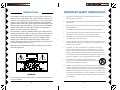
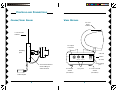
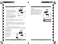
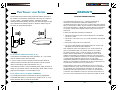
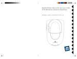
Indoor/Outdoor Color Camera
with Built-in 2.4 GHz Wireless
Video Sender, plus X10
controlled power supply, and
separate Video Receiver.
OWNER'S MANUAL
VR31A
XC16A
XM10A
MODEL VK58A
(INCLUDES XC16A C AMERA, XM10A ADDRESSABLE
POWER SUPPLY, AND VR31A VIDEO RECEIVER)
INTRODUCTION
Your Wireless Camera Kit consists of a Color Video Camera with
built-in 2.4 GHz Video Sender, and a Video Receiver unit which you
connect to a TV anywhere in your home (up to 100 ft. away from the
Camera). The Camera/Video Sender converts the video and audio
signals from the camera into a radio signals and transmits them (even
through walls) to the Video Receiver. The Video Receiver converts the
signals back to video and audio signals which are fed through a
cable to your TV's COAX or A/V input jacks.
Also included is a remote controlled power supply, Model XM10A,
which lets you turn the camera on and off by remote control from any
X10 remote control (sold separately). You can purchase additional
cameras and power supplies so you can have a multiple camera
system. You can then set all cameras to the same channel as the
receiver and turn the cameras on and off remotely so as to only ever
have one camera turned on at a time.
There are just a few simple steps to follow to hook up your Camera
and Video Sender kit.
IMPORTANT SAFETY INSTRUCTIONS
1.
Read Instructions - All the safety and operating instructions should be read
before the product is operated.
2.
Retain Instructions - The safety and operating instructions should be retained for
future reference.
3.
Heed Warnings - All warnings on the product and in the operating instructions
should be adhered to.
4.
Follow Instructions - All operating and use instructions should be followed.
5.
Cleaning - Unplug this product from the wall outlet before cleaning. Do not use
liquid cleaners or aerosol cleaners. Use a damp cloth for cleaning.
6.
Attachments - Do not use attachments not recommended by the product
manufacturer as they may cause hazards.
7.
Water and Moisture - Do not use this product near water - for Example, near a
bath tub, wash bowl, kitchen sink, or laundry tub, in a wet basement, or near a
swimming pool; and the like.
8.
Accessories - Do not place this product on an unstable cart, stand, tripod,
bracket, or table. The product may fall, causing serious injury to a child or
adult, and serious damage to the product. Use only with a cart, stand, tripod,
bracket, or table recommended by the manufacturer, or sold with the product.
Any mounting of the product should follow the manufacturer’s instructions, and
should use a mounting accessory recommended by the manufacturer.
9.
A product and cart combination should be moved with care.
Quick stops, excessive force and uneven surfaces may cause the
product and cart combination to overturn.
10. Ventilation - Slots and openings in the cabinet are provided for ventilation and
to ensure reliable operation of the product and to protect if from overheating,
and these openings must not be blocked or covered. The openings should never
be blocked by placing the product on a bed, sofa, rug, or other similar surface.
This product should not be placed in a built-in installation such as a bookcase or
WARNING:
To reduce the risk of fire or electric shock, do not expose this product
to rain or moisture.
2
rack unless proper ventilation is provided or the manufacturer’s instructions have
been adhered to.
3
11. Power Sources - This product should be operated only from the type of power
source indicated on the marking label. If you are not sure of the type or power
supply to your home, consult your product dealer or local power company. For
c)
If the product has been exposed to rain or water,
d)
If the product does not operate normally by following the operating instructions.
Adjust only those controls that are covered by the operating instructions as an
products intended to operate from battery power, or other sources, refer to the
improper adjustment of other controls may result in damage and will often
operating instructions.
require extensive work by a qualified technician to restore the product to its
normal operation,
12. Grounding or Polarization - This product is equipped with a polarized
alternating current line plug (a plug having one blade wider than the other).
This plug will fit into the power outlet only one way. This is a safety feature. If
you are unable to insert the plug fully into the cutlet, try reversing the plug. If the
plug should still fail to fit, contact your electrician to replace your obsolete
outlet. Do not defeat the safety purpose of the polarized plug.
13. Power-Cord Protection - Power supply cords should be routed so that they are
not likely to be walked on or pinched by items placed upon or against them,
paying particular attention to cords at plugs, convenience receptacles, and the
point where they exit from the product.
14. Lightning - For added protection for this product during a lightning storm, or
when it is left unattended and unused for long periods of time, unplug it from
the wall outlet and disconnect the antenna or cable system. This will prevent
damage to the product due to lightning and power-line surges.
15. Overloading - Do not overload wall outlets, extension cords, or integral
convenience receptacles as this can result in a risk of fire or electric shock.
16. Object and Liquid Entry - Never push objects of any kind into this product
through openings as they may touch dangerous voltage points or short-out parts
that could result in a fire or electric shock. Never spill liquid of any kind on the
product.
17. Servicing - Do not attempt to service this product yourself as opening or
e)
If the product has been dropped or damaged in any way, and
f)
When the product exhibits a distinct change in performance - this indicates a
need for service.
19. Heat - The product should be situated away from heat sources such as
radiators, heat registers, stoves, or other products including amplifiers) that
produce heat.
FCC CAUTION
THIS DEVICE COMPLIES WITH PART 15 OF THE FCC RULES.
OPERATION IS SUBJECT TO THE FOLLOWING TWO CONDITIONS:
(1)THIS DEVICE MAY NOT CAUSE HARMFUL INTERFERENCE, AND
(2)THIS DEVICE MUST ACCEPT ANY INTERFERENCE RECEIVED, INCLUDING
INTERFERENCE THAT MAY CAUSE UNDESIRED OPERATION.
This equipment generates and uses radio frequency energy, and if not installed and
used properly, that is, in strict accordance with the manufacturers instructions, it may
cause interference to radio and television reception. It has been type tested and
found to comply with the limits for remote control devices in accordance with the
specifications in Sub-Parts B and C of Part 15 of FCC Rules, which are designed to
provide reasonable protection against such interference in a residential installation.
However, there is no guarantee that interference will not occur in a particular
installation. If this equipment does cause interference to radio or television reception,
which can be determined by unplugging the equipment, try to correct the interference
by one or more of the following measures.
removing covers may expose you to dangerous voltage or other hazards. Refer
• Reorient the antenna of the radio/TV experiencing the interference.
all servicing to qualified service personnel.
• Relocate the equipment with respect to the radio/TV.
18. Damage Requiring Service - Unplug this product from the wall outlet and refer
• Move the equipment away from the radio/TV.
servicing to qualified service personnel under the following conditions:
• Plug the equipment into an outlet on a different electrical circuit from the radio/TV
experiencing the interference.
a)
When the power-supply cord or plug is damaged,
• If necessary, consult your local Dealer for additional suggestions.
b)
If liquid has been spilled, or objects have fallen into the product,
NOTE: Modifications to this product will void the user's authority to operate this
equipment.
4
5
CONTENTS
CONTROLS
AND
CONNECTIONS ........................................ 7
CAMERA/VIDEO SENDER, REMOTE CONTROLLED .......................
POWER SUPPLY, AND VIDEO RECEIVER ................................ 7
CAMERA/VIDEO SENDER .................................................. 8
VIDEO RECEIVER ............................................................. 9
CONTROLS
AND
CONNECTIONS
CAMERA/VIDEO
SENDER
VIDEO R ECEIVER
(BOTTOM VIEW)
TV
2.4 GHz
Video
Antenna
Channel
Switch
CONNECTING UP ........................................................... 10
SETTING
UP THE
REMOTE CONTROLLED POWER SUPPLY .......... 10
SETTING
UP THE
CAMERA /VIDEO SENDER ........................... 11
SETTING
UP THE
VIDEO RECEIVER ...................................... 12
FINE
TUNING YOUR
TV
CHAN NEL
3 4
VR31A
SYSTEM ........................................... 14
WARRANTY ................................................................... 15
XC16A
CH AN NEL
A BC D
2.4 GHz
Channel
Switch
Power Supply
Socket
XM10A
Used to set the code that the XM10A
responds to, so you can turn the camera
connected to it on and off by remote control
(using X10 remote controls, sold separately).
6
7
CONTROLS
AND
CONNECTIONS
CAMERA/VIDEO SENDER
VIDEO RECEIVER
2.4 GHz
Video
Antenna
2.4 GHz Video
Antenna
TV Output
Connector
Mounting
plate
ON-OFF
TO TV
Switch
VIDEO OUT AUDIO OUT
Set channel switch to
match setting on
Video Receiver.
Power Supply
Jack
TV Channel
Switch
2.4 GHz Channel
Switch
A/V Jacks
(on bottom)
Cable adapter.
8
(on side)
DC 12V
(on bottom)
9
CONNECTING UP
SETTING UP THE CAMERA /VIDEO SENDER,
CONTROLLED POWER SUPPLY
AND
REMOTE
Referring to the diagrams below and on the next page:
2.4 GHz Video
Antenna
Set channel switch to
match setting on
Video Receiver.
1. Attach the camera to a wall using the screws provided.
2. If you install the camera outdoors, make a small hole in your
exterior wall and pass the low voltage power jack through it.
3. Plug the XM10A's power supply jack into the socket on the
adapter cable from the camera.
4. Plug the power supply into any 120V AC outlet.
5. Set the channel switch on the camera to any letter A, B, C, or D
Attach camera to a
wall, indoors or
outdoors.
6. Adjust the antenna if necessary to aim it in the direction of the TV
or monitor that you will view the camera on.
7. Set the Housecode dial to a letter between A
and P that matches the Housecode dial on the
X10 remote controls you want to use it with. Set
the Unit Code dial to a number between 1 and
16. This lets you turn the camera connected to
the XM10A on and off by remote control (using
X10 remote controls, sold separately). See the
owner's manual supplied with X10 remote
controls for more details.
Outdoors
Indoors
Plug power
supply in here.
Plug into
any AC
outlet
Set codes
wheels.
Important: Unplug
power supply before
unplugging power jack.
10
11
HOOKING
UP THE
VIDEO RECEIVER
IF YOUR TV IS
A/V DEVICE
1. Connect a set of Audio/Video
cables to the A/V OUT jacks on the
Video Receiver. Connect the other
end to your TV (use either L or R
channel for audio).
VIDE O
A UDIO
TO TV
TV
2. Plug the Video Receiver's Power
Supply jack (the power supply with
NO code wheels) into the Video
Receiver and plug the power supply
into a 120 volt wall outlet.
ALREADY HOOKED UP TO A
DBS RECEIVER OR OTHER
If a DBS Receiver or other A/V
component is connected to the TV using
A/V cables, you can connect the Video
Receiver to the free LINE IN jacks on
the component. If there are no LINE IN
jacks, you will need to use a TV
antenna splitter as described earlier.
VIDE O
TV
AUDIO
VIDEO
VIDEO
AUDIO
VIDEO
AUDIO
3. Turn the Video Receiver's power switch (on side of unit) on.
OUT
4. Set the channel switch to the same letter as you set on the
camera, A, B, C, or D.
IN
5. Position the Video Receiver in a convenient location such as on
top of the TV and orient the antenna so that the flat side points in
the direction of the room where you set up the Camera/Video
Sender.
IF
YOUR
TV DOES
NOT HAVE
A/V
CONNECTORS
You can use the supplied coaxial cable to connect the TV OUT socket
on the Video Receiver to the Antenna input on your TV. If you already
have an antenna
connected to your TV,
you will need to use a
TV antenna splitter.
TO TV
Set your TV and the
TV Channel switch on
the Video Receiver
(on bottom) to the
same channel (3 or
4).
VIDE O
A UDIO
TO TV
ANTENNA
TV
1
2
UHF/VHF
ANTENNA
12
A UDIO
TOTV
13
DS S
FINE TUNING
YOUR
SYSTEM
The Wireless Video Sender usually works best with the flat faces of
the antennas on the Sender and Receiver unit facing each other (i.e.
in “Line of sight” - see diagram below). Sometimes, however,
reflections and other effects in the home may affect the signal so that
some adjustment of either the Sender or Receiver antenna may be
necessary to get the best the signal.
WARRANTY
12 MONTH LIMITED WARRANTY
X10 WIRELESS TECHNOLOGY, INC. (X10WTI) WARRANTS ITS
PRODUCTS TO BE FREE FROM DEFECTIVE MATERIAL AND
WORKMANSHIP FOR A PERIOD OF ONE (1) YEAR FROM THE ORIGINAL
DATE OF PURCHASE AT RETAIL. X10WTI AGREES TO REPAIR OR REPLACE,
AT ITS SOLE DISCRETION, A DEFECTIVE X10WTI PRODUCT IF RETURNED
TO X10WTI WITHIN THE WARRANTY PERIOD AND WITH PROOF OF
PURCHASE.
IF SERVICE IS REQUIRED UNDER THIS WARRANTY:
1. RETURN THE DEFECTIVE UNIT POSTAGE PREPAID TO THE ADDRESS
ON BACK COVER.
2. ENCLOSE A CHECK FOR $4.00 TO COVER HANDLING AND RETURN
POSTAGE.
3. ENCLOSE A DATED PROOF OF PURCHASE.
4. X10 IS NOT RESPONSIBLE FOR SHIPPING DAMAGE. UNITS TO BE
RETURNED SHOULD BE PACKED CAREFULLY.
IF
YOU ARE NOT GETTING ANY SIGNAL AT ALL
Check that the CHANNEL slide switch (labeled A, B, C, D) on both
units (on bottom) is set to the same letter.
If you are using coaxial TV connections from the Video Receiver,
check that the TV is tuned to the same channel as the TV Channel
switch on the bottom of the Video Receiver (3 or 4).
Check that the camera's remote controlled power supply is turned on
(using any X10 remote control, sold separately). Note, when you first
plug the power supply in, it will normally be ON.
IF
THE SIGNAL IS POOR, OR THERE IS INTERFERENCE
THIS WARRANTY DOES NOT EXTEND TO ANY X10WTI PRODUCTS
WHICH HAVE BEEN SUBJECT TO MISUSE, NEGLECT, ACCIDENT,
INCORRECT WIRING OR TO USE IN VIOLATION OF OPERATING
INSTRUCTIONS FURNISHED BY US, NOR EXTEND TO ANY UNITS
ALTERED OR REPAIRED FOR WARRANTY DEFECT BY ANYONE OTHER
THAN X10. THIS WARRANTY DOES NOT COVER ANY INCIDENTAL OR
CONSEQUENTIAL DAMAGES AND IS IN LIEU OF ALL OTHER
WARRANTIES EXPRESSED OR IMPLIED AND NO REPRESENTATIVE OR
PERSON IS AUTHORIZED TO ASSUME FOR US ANY OTHER LIABILITY IN
CONNECTION WITH THE SALE OF OUR PRODUCTS.
SOME STATES DO NOT ALLOW LIMITATIONS ON HOW LONG AN
IMPLIED WARRANTY LASTS, AND/OR THE EXCLUSION OR LIMITATION
OF INCIDENTAL OR CONSEQUENTIAL DAMAGES SO THE ABOVE
LIMITATIONS AND EXCLUSIONS MAY NOT APPLY TO THE ORIGINAL
CUSTOMER. THIS WARRANTY GIVES YOU SPECIFIC RIGHTS AND YOU
MAY ALSO HAVE OTHER RIGHTS WHICH VARY FROM STATE TO STATE.
Try changing the channel on both units. Do this by adjusting the
CHANNEL slide switch on each unit to any position (A, B, C, or D).
Make sure both units are set to the same letter.
14
15
X10.com, a Division of
X10 Wireless Technology, Inc.
3824 North 5th St.,
Suite C, North Las Vegas, NV 89030
Web Site: www.x10.com
VK58A-11/3/00
16