Transcript
SETUP
INSTRUCTIONS
8 Camera Total Surveillance Kit
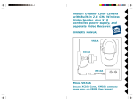
use should not be too close to the back of your PC, as
your PC may create some electrical noise that will reduce
the range of the transceiver. Set the House Code (letter
dial) on the Wireless Link to the letter you used for your
cameras.
Set up VCR Commander
Your X10 8 camera kit gives you two complete surveillance
systems. This kit is designed to allow you to use your TV and
the ScanPad remote to view 4 cameras, and use your PC to
view another 4 cameras at home and over the Internet. Follow
these instructions to set up the cameras and receivers. See
the XRay Vision instructions and help file for more complete
information about setting up the software and hardware on
your PC.
Set Up Your Cameras
You have two 4-camera systems to set up. First
set up the two video receivers (model VR31A).
Set the frequency channel switch on the bottom
of one receiver to 'A' and the other one to 'D.' Connect receiver
'A' to your VCR. The Video Receiver manual has diagrams
and descriptions for different ways to do so. Connect the
other receiver to the XRay Vision video capture adapter (see
XRay Vision instructions for details).
Next, set the House and Unit code dials on the addressable
power supplies (model XM10A) of the first four cameras to
the same letter ('A' for example) and then numbers 1 through
4, respectively. Plug each power supply into a free AC outlet.
Connect the camera to the power supply. The camera should
come on and you should be able to get the picture on the TV.
Adjust the antenna so that it points better at the antenna of
the receiver. When the camera is set up, turn it off using your
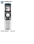
ScanPad remote (model CR12A). Repeat these steps for
each camera you are setting up. Make sure to choose a
different Unit Code for each camera.
Set the dials on the power supplies of the next for cameras
to the same House Code (letter dial) and set the number dials
to 5 through 8. Remove the rubber plug (it looks like a button)
on the base of each camera to open frequency channel switch.
The positions on the switch are not labeled, but the positions
match the 'A' to 'D' settings on the video receiver. Using a
paper clip or other small implement, move the switch on the
base of each camera to the top-most position, setting 'D'.
This sets the cameras to work with the receiver connected
to your PC.
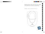
One of the motion sensors from the first set
of cameras (numbers 1-4) that you set up above
will also be used to trigger VCR Commander
to start recording video. Follow the instructions
in the VCR Commander box to program this address into
the UX21A and learn the commands to record on your
VCR.
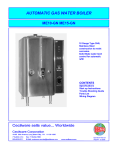
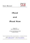
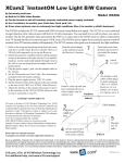
Connect the Firecracker Computer Interface
The Computer Interface
(model CM17A) uses
wireless signals to transmit
X10 control commands from the
computer to the transceiver module
included in the kit. Connect the Interface
directly to your PC's serial port. If there
is already a device connected to this
port, unplug it, connect the Computer
Interface, and then plug the other device into the connector
on the CM17A. Important: Do not plug your mouse into
the CM17A!
Configure Your Cameras in XRay Vision
Run XRay Vision. Right click in the program
window and choose "Settings" then
"Preferences" from the pop-up menu. Click on
the "Cameras" tab in the configuration window.
Click on the "Add" button to create an entry for a camera.
Click into the "Camera Code" box and enter the House
and Unit code for this camera. Make sure to enter the
letter and number without a space between them. In the
"Comment" box you can type a description or name for
this camera. Repeat these steps for all the second set of
cameras (numbers 5-8) you configured above.
You are now ready to control your cameras from XRay
Vision. Right click in the XRV window and choose
"Camera." You will be able to select from your different
cameras, or tell XRV to automatically switch between all
of them.
Set Up Motion Detectors
Follow the instructions included with the HawkEye
and Eagle Eye motions sensors to configure one
sensor for each camera you set up earlier, numbers
1 through 8. Mount each motion sensor in a location near the
corresponding camera.
Set Up the Wireless Link
Make sure you have
connected the Wireless Link
(model TM751) to a nearby
power outlet. The outlet you
MODEL
NUMBER:
IN39A
#99081-DHADAa
©Copyright 2000 X10 Wireless Technology, Inc.