1
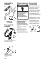
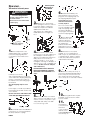
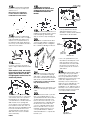
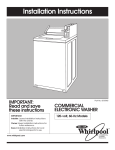
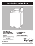
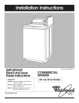
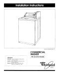
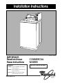
Installation Instructions
Part No. 3360620
IMPORTANT:
Read and save
these instructions
IMPORTANT
Installer: Leave Installation Instructions
with the owner.
Owner: Keep Installation Instructions for
future reference.
Save Installation Instructions for local
electrical inspector’s use.
www.whirlpool.com
COMMERCIAL
WASHER
120-volt, 60-Hz Models
®
COMMERCIAL
LAUNDRY
PRODUCTS
Before you start...
Your safety and the safety of
others is very important.
We have provided many important
safety messages in this manual and on
your appliance. Always read and obey all
safety messages.
This is the safety alert
symbol. This symbol alerts
you to hazards that can kill or
hurt you and others. All safety
messages will be preceded by the safety
alert symbol and the word “DANGER” or
“WARNING”. These words mean:
Check location where washer will be
installed. Proper installation is your
responsibility. Make sure you have
everything necessary for correct
installation.
Do Not store or operate washer below
32°F some water may remain in
washer).
DANGER
You will be killed or seriously injured if
you don’t follow instructions.
WARNING
You can be killed or seriously injured if
you don’t follow instructions.
All safety messages will identify the hazard,
tell you how to reduce the chance of injury,
and tell you what can happen if the
instructions are not followed.
Single washer
installations require
12” minimum risers
to provide an air
cushion and
prevent noise and
damage to valves.
Grounded
electrical outlet
is required. See
Electrical
requirements.
Coin-operated washers are equipped
with a meter case, console, timer,
selector switches and indicator lights.
The coin slide mechanism, slide
mounting bolt, slide extension, service
door panel lock and key, top lock
and key, coin vault, and coin vault
lock and key are not included with
this washer and are needed to
complete installation. These items are
available from usual industry sources.
Hot and cold water faucets must be
within 4 feet of the back of the
washer and provide water pressure
10-100 PSI. A pressure reduction valve
should be used in the supply line
where inlet pressure entering the
building exceeds 100 PSI to prevent
damage to the washer mixing valve.
See Use & Care Guide for
“Winterizing” information.
Untape and
open washer
lid. Remove
packages and
hoses from
washer.
No. T20 Torx
screws
On coin-operated washers, front
access to the pump area is available
by removing the two, No. 10 Torx
screws and then removing the front
panel. Non-coin-operated washers
do not have a removable front panel.
The cabinet and top assembly must
be removed by removing clips under
console on the non-coin-operated
washer.
PAGE 2
Water heater: Set
to deliver 140°F to
160°F water to the
washer.
Level floor: Maximum slope
under washer — 1 inch
A floor drain should be provided
under the bulkhead. Prefabricated
bulkheads with electrical outlets,
water supply lines and drain facilities
should be used only where local
codes permit.
Non-coin-operated washers are
equipped with a console, push to
start timer, selector switches and
indicator lights (not pictured).
Standpipe drain system: Needs a twoinch minimum carry-away capacity
of 17 gallons per minute. Top of
standpipe must be at least 34 inches
high and no higher than 72 inches
from bottom of washer.
Support: Floor must be sturdy enough
to support loaded washer weight of
315 pounds.
Important: Observe all governing
codes and ordinances.
Tools needed for
installation:
level
Electrical requirements Recommended
ground method
WARNING
pliers
Electrical Shock Hazard
Plug into a grounded 3-prong outlet.
Do not remove ground prong.
Do not use an adapter.
Do not use an extension cord.
Failure to follow these instructions
can result in death, fire, or electrical
shock.
wrench
flat-blade
screwdriver
utility
knife
scissors
T20 torx driver
Parts supplied for
installation:
s
If codes permit and a separate ground
wire is used, it is recommended that a
qualified electrician determine that
the ground path is adequate.
Do Not ground to a gas pipe.
Check with a qualified electrician if
you are not sure the washer is properly
grounded.
Do Not have a fuse in the neutral or
ground circuit.
A 120-volt, 60-Hz, AC-only, 15- or
20-ampere fused electrical supply is
required. (Time-delay fuse or circuit
breaker is recommended.) It is
recommended that a separate circuit
serving only this appliance be provided.
Remove parts from packages. Check
that all parts were included.
1 hose clamp
2 inlet hoses
4 flat water hose washers
2 front-leveling legs with nuts
1 drain hose
PAGE 3
For your personal safety, this appliance
must be grounded. This appliance is
equipped with a power supply cord
having 3-prong ground plug. To
minimize possible shock hazard, the
cord must be plugged into a mating 3prong ground-type outlet, grounded in
accordance with local codes and
ordinances. See Figure 1. If a mating
outlet is not available, it is the personal
responsibility and obligation of the
customer to have a properly grounded
3-prong outlet installed by a qualified
electrician.
Warning – Improper connection of the
equipment-grounding conductor can
result in a risk of electric shock. Check
with a qualified electrician or
serviceman if you are in doubt as to
whether the appliance is properly
grounded. Do not modify the plug
provided with the appliance – if it will
not fit the outlet, have a proper outlet
installed by a qualified electrician.
3-prong
ground
plug
3-prong groundtype outlet
ground
prong
power
supply cord
Figure 1
Now start...
Inlets are plastic.
Do Not strip or
crossthread.
With washer in laundry area.
WARNING
Excessive Weight Hazard
Use two or more people to move
and install washer.
Failure to do so can result in back
or other injury.
6.
Measure and mark a point
approximately 16 inches from the
plug end of the shipping strap. Cut
this shipping strap at this point.
3.
Attach hose to bottom inlet
valve opening first. Then second hose
to top inlet. Tighten couplings by
hand; then use pliers to make an
additional two-thirds turn.
Slide washer onto cardboard or
hardboard before moving across
floor.
Pull the strap completely
out of the washer.
Remove tape that covers
shipping strap. Pull to completely
remove the shipping strap with
2 cotterpins from the inside of the
washer.
4.
Move washer close to final
position. Put “hook” end of drain hose
into standpipe. Estimate length of
drain hose needed when washer is in
final position. Hose must be cut
exactly to length so “hook” end is
held tightly over edge of standpipe. If
drain hose is too long, cut straight end
of hose. (Do Not cut “hook” shaped
end of drain hose.)
DO NOT FORCE EXCESS LENGTH OF
DRAIN HOSE DOWN THE STANDPIPE.
THIS COULD CAUSE SIPHONING. See
Step 6.
Pull firmly to remove the
end of shipping strap from the back
of the washer. The shipping strap plug
must be completely removed from
the washer for the self-leveling legs to
be released.
Save the shipping strap for use in
Step 6.
Power supply cord is factory installed.
Peel the tape down and off each side
of the cabinet.
Use the new hoses and washers that
came with your Whirlpool washer.
2.
washer
Insert a flat washer into each end
of the inlet hoses. Check that washers
are firmly seated in couplings.
PAGE 4
Put “hook” end of drain
hose into standpipe. Tightly
wrap the shipping strap
around the standpipe.
Push plug into the nearest
hole in the shipping strap.
7.
8.
Attach bottom hose (inlet
marked “H”) to hot water faucet.
Attach top hose (inlet marked “C”) to
cold water faucet. Tighten coupling
to faucet by hand; then use pliers to
make final two-thirds turn.
9.
Stack two corner posts on top of
each other. Tilt washer backwards and
insert corner posts 3 inches in from one
side of washer as shown. Repeat with
other corner posts on other side of washer.
1/2"
base
nut
5.
Place hose clamp over washer
drain connector. Push drain hose onto
washer connector. use pliers to open
clamp and slide clamp over drain
hose. Check for good fit.
coupling
Check that hose is not
twisted or kinked and is
securely in place.
Before attaching
water inlet hoses, run
water through both
faucets into a bucket.
This will get rid of
particles in water lines
that might clog hoses.
Mark which is the hot water faucet.
shipping
tape
1.
16"
10.
Use legs and nuts from parts
package. Screw nut down to within
1/2 inch of base.
11.
Insert legs into
correct holes at
each front
corner of washer
until nuts touch
washer. Do Not tighten
nuts until Step 15.
12.
Tilt washer backward and
remove corner posts. Gently lower
washer to floor.
Move washer to its permanent
location. Remove cardboard or
hardboard from under washer.
Rotate counterclockwise only.
18.
CHECK ELECTRICAL
REQUIREMENTS. BE SURE YOU HAVE
CORRECT ELECTRICAL SUPPLY AND
RECOMMENDED GROUNDING
METHOD.
timer “off”
position
timer-front view
e
ns
ain
Dr
cycle
information
in
Turn on water faucets and
check for leaks. Tighten couplings if
there is leaking. Do Not overtighten;
this could cause damage to faucets.
Rotation
20.
Sp
in
Sp
in
Dra
Wash
Tilt washer forward raising
back legs 1 inch off of floor. To adjust
rear self-leveling legs, gently lower
washer to floor. Check levelness of
the washer by placing a carpenter’s
level on top of the washer, first side to
side; then front to back.
Off
13.
Check that all parts are now
installed. See parts list, Page 3. If there
is an extra part, go back through
steps to see which step was skipped.
Ri
19.
• Coin-operated timers can be
started by turning the clutch
assembly counterclockwise until the
washer starts to fill with water.
lever
pull to start
push to stop
timer-rear view
• Non-coin-operated timer cycle
information is ink stamped on the
rear of the timer. Push in on the
lever attached to the timer shaft.
Reset lever to the Normal cycle
position, then pull out on lever to
start washer.
14.
If washer is
not level, screw the front legs up or
down to adjust. Make final check with
level.
When washer is level, use wrench
to turn nuts on front legs up tightly
against washer base. If nuts are
not tight against washer base, the
washer may vibrate.
21.
Check that you have all of
your tools. Check that the shipping
strap with 2 cotterpins and plug was
removed from the back of the washer
and used to secure the drain hose.
If entire strap is not removed, washer
may vibrate and be noisy.
bolt
15.
On coin-operated washers,
remove the service door of the meter
case. Lift the service door up at the
back and remove. Carefully insert
coin slide with the coin slide extension
attached into front opening and
secure with the 3/16" mounting bolt
from inside the meter case. The coin
slide may need to be partially pushed
in to insert mechanism in the front
opening. Replace meter case top
and service door. Insert coin vault
with lock and key.
PAGE 5
22.
Remove power supply cord
from basket and plug into grounded
outlet.
24.
If the washer fails to start or
does not give the proper washer
cycle time, the clutch assembly of
the coin-operated timer can be
adjusted. Remove the timer from the
meter case. Adjust the clutch
assembly screw clockwise, if the
washer does not start after the coin
slide mechanism has been fully
actuated in or out. Adjust the clutch
assembly screw counterclockwise if
the washer segment of the Normal
cycle was less than 9 minutes.
23.
Check the wash cycle time.
Both coin-operated and non-coinoperated washers have timers with a
9-minute wash in the Normal cycle.
Remove the meter case top of coinoperated washers to manually start
the timer. Remove the rear of the
console to manually start the timer.
Remove the rear of the console to
manually operate the timer of noncoin-operated washers. Start the
washer and allow it to complete the
Normal cycle.
timer clutch
adjustment screw
Owner options (coinoperated models)
CAUTION: Disconnect power cord.
1. For EXTRA SPIN and/or EXTRA WASH.
• Remove meter case service
door
• Loosen (2) screws on the timer
mounting bracket and lift the
timer out.
(2) screws
a. EXTRA WASH — 3 minutes.
• Connect LBU to LBU2.
• Disconnect GY from GY2.
• Set timer clutch arm as shown
below.
Extra Wash
Standard Wash
Leave “⊥” on timer
shaft aligned with “⊥”
on timer and move
timer clutch arm to
“extra” wash position.
b. EXTRA SPIN — 2 minutes.
• Connect BK to BK2
2. For WARM RINSE and WATER SAVER:
• Remove screws from each end
of the console bottom.
• Pull the console bottom
forward; lift and tilt it back.
a. WARM RINSE
• Connect J1 to J2
b. SAVE WATER
• Pull out tab on water-level
switch.
3. If use of a larger coin vault, lock
and key is desired, conversion bar
in lower portion of coin vault area
can be removed.
4. If additional security is needed, top
and cabinet can be locked to
washer back panel by using a
“screw type” lock and key in space
provided in top panel under
console. The “screw type” lock and
key are available from usual
industry sources.
PAGE 6
Typical full load sizes.
Load Type
Loading Suggestion
Load Type
Loading Suggestion
Mixed
Load
3 double sheets
4 pillowcases
8 T-shirts
6 pair shorts
2 shirts
2 blouses
8 handkerchiefs
Heavy
work
clothes
3 pair pants
3 shirts
1 coverall
4 pair jeans
1 overall
Knits
3 blouses
4 slacks
6 shirts
4 tops
4 dresses
Permanent 2 double or
Press
1 king size sheet
1 tablecloth
1 dress
1 blouse
2 slacks
3 shirts
2 pillowcases
Check list for washer
operation.
Check the following if the washer is
not operating properly:
1. Power supply cord is plugged in.
2. Circuit breaker is not tripped or
house fuse blown.
3. Timer has been advanced to start
of a cycle.
4. Water faucets are turned on.
5. Inlet and drain hoses are not kinked.
6. Washer lid is closed.
7. Inlet valve is frozen if not protected
from the weather.
8. Suds level. Excess suds will slow the
spin and cause poor rinsing.
Operate the washer through a
complete cycle with no detergent.
Use less detergent or a controlled
suds type detergent in future loads.
It is recommended that fiberglass
items not be washed in coin-operated
washers. If these items are washed in
the washer, run the washer through a
complete cycle to rinse any residue
away that might be left in the washer.
Moving the washer to
a new location...
Wedge blanket
between tub ring
and cabinet top.
Remove front legs.
Tape rear
legs in “up” Tape 2
sides.
position.
Operating Tips.
WARNING
Note: Do Not
place blanket
in this area
(switch).
Explosion Hazard
Never place items in the washer that
are dampened with gasoline or
other flammable fluids.
No washer can completely remove oil.
Do not dry anything that has ever
had any type of oil on it (including
cooking oils).
Doing so can result in death,
explosion, or fire.
• Remove the front legs from the
base of the washer.
• Place both rear leveling legs in the
upper position and tape securely.
• Apply tape to the side and bottom
of the cabinet near the rear.
• Open washer lid, wedge a blanket
between the tub ring and the
cabinet top restricting the tub
movement.
• Handle washer carefully. Do Not
drop washer while using hand truck.
7"
power cord
cold
1-1/2"
hot
43"
water
Inlets
38-1/8"
35"
drain hose
connector
27-3/4"
7"
25-1/2"
5"
5-1/4"
1"
PAGE 7
27"
Part No. 3360620
©1999 Whirlpool Corporation
Prepared by Whirlpool Corporation, Benton Harbor, Michigan 49022
Printed in U.S.A.